A Self-Reconfigurable Modular Robot: Reconfiguration ... · National Institute of Advanced...
19
A Self-Reconfigurable Modular Robot: Reconfiguration Planning and Experiments Eiichi Yoshida, Satoshi Murata, Akiya Kamimura, Kohji Tomita, Haruhisa Kurokawa, and Shigeru Kokaji Distributed System Design Research Group, Intelligent Systems Institute, National Institute of Advanced Industrial Science and Technology (AIST) 1-2-1 Namiki, Tsukuba-shi, Ibaraki 305-8564 Japan [email protected] Abstract This paper addresses a reconfiguration planning method for locomotion of a homogeneous modular robotic system and conducts an experiment to verify that the planned locomotion can be realized by hardware. Our recently developed module is self-reconfigurable. A group of the modules can thus generate various three-dimensional robotic structures and motions. Although the module itself is a simple mechanism, self-reconfiguration planning for locomotion presents a computationally difficult problem due to the many combinatorial possibilities of modular config- urations. In this paper, we develop a two-layered planning method for locomotion of a class of regular structures. This locomotion mode is based on multi-module blocks. The upper layer plans the overall cluster motion called flow to realize locomotion along a given desired trajectory; the lower layer determines locally cooperative module motions, called motion schemes, based on a rule database. A planning simulation demonstrates that this approach effectively solves the com- plicated planning problem. Besides the fundamental motion capacity of the module, the hardware feasibility of the planning locomotion is verified through a self-reconfiguration experiment using the prototype modules we have developed. 1 Introduction In recent years, the feasibility of reconfigurable robotic systems has been examined through hardware and software experiments in two dimensions [1]–[8] and three dimensions [9]–[16]. Specifically, a self-reconfigurable robot can adapt itself to the external environments. It can also repair itself by using spare modules owing to the homogeneity of the module. This paper focuses on the reconfiguration
Transcript of A Self-Reconfigurable Modular Robot: Reconfiguration ... · National Institute of Advanced...

A Self-Reconfigurable Modular Robot:
Reconfiguration Planning and Experiments
Eiichi Yoshida, Satoshi Murata, Akiya Kamimura,
Kohji Tomita, Haruhisa Kurokawa, and Shigeru Kokaji
Distributed System Design Research Group, Intelligent Systems Institute,
National Institute of Advanced Industrial Science and Technology (AIST)
1-2-1 Namiki, Tsukuba-shi, Ibaraki 305-8564 Japan
Abstract
This paper addresses a reconfiguration planning method for locomotion of a homogeneous
modular robotic system and conducts an experiment to verify that the planned locomotion can
be realized by hardware. Our recently developed module is self-reconfigurable. A group of the
modules can thus generate various three-dimensional robotic structures and motions. Although
the module itself is a simple mechanism, self-reconfiguration planning for locomotion presents a
computationally difficult problem due to the many combinatorial possibilities of modular config-
urations. In this paper, we develop a two-layered planning method for locomotion of a class of
regular structures. This locomotion mode is based on multi-module blocks. The upper layer plans
the overall cluster motion called flow to realize locomotion along a given desired trajectory; the
lower layer determines locally cooperative module motions, called motion schemes, based on a
rule database. A planning simulation demonstrates that this approach effectively solves the com-
plicated planning problem. Besides the fundamental motion capacity of the module, the hardware
feasibility of the planning locomotion is verified through a self-reconfiguration experiment using
the prototype modules we have developed.
1 Introduction
In recent years, the feasibility of reconfigurable robotic systems has been examined through hardware
and software experiments in two dimensions [1]–[8] and three dimensions [9]–[16]. Specifically, a
self-reconfigurable robot can adapt itself to the external environments. It can also repair itself by using
spare modules owing to the homogeneity of the module. This paper focuses on the reconfiguration
planning for a new type homogeneous, self-reconfigurable modular robot that enables movement in
three dimensions by changing the configuration. Its various potential applications include structures
or robots that operate in extreme environments inaccessible to humans, for example, in space, deep
sea, or nuclear plants.
Hardware of three-dimensional self-reconfigurable modular robots is classified into two types, the
lattice type [9, 10, 17, 19, 18] and the linear type [13, 16]. The former corresponds to a system where
each module has several fixed connection directions, and a group of them can construct various static
structures like a jungle gym. However, it is difficult for such a system to generate wave-like motions
involving many modules at the same time. In contrast, the latter (linear type) has a shape that can
generate various robotic motions like a snake or a caterpillar, but self-reconfiguration is difficult.
There have been a number of studies on the software of lattice-type reconfigurable modular robots.
Distributed self-reconfiguration methods have also been developed for two- and three-dimensional
homogeneous modular robots [5]–[7],[14],[18]. The first method [5] has already been implemented in
a two-dimensional hardware system with more than ten modules to demonstrate the self-assembly and
self-repair capacity. The others have been investigated in simulations to be implemented in hardware
in future developments. There are also other methods based on centralized planning. Kotay et al.
[11, 22] developed robotic modules and described a global motion synthesis method for a class of
module groups to move in arbitrary directions. Unsal et al. [17] reported two-level motion planners
for a bipartite module composed of cubes and links, based on a heuristic graph search among module
configurations.
We have recently developed a new type of modular robotic system that has both lattice type and
linear type features [15]. The module has a simple bipartite structure in which each part rotates about
an axis parallel to the other’s by a servomotor and has three magnetic connecting faces. This re-
cent module can form various shapes, such as a legged walking robot or a crawler-type robot (see
Multimedia Extension 4 [M4] for an example of transformation between these locomotion modes).
However, its reconfiguration planning is not straightforward because of restricted degrees of free-
dom and non-isotropic geometrical properties of mobility of a module unlike lattice-type modules
in previous research. When a module moves from one position to another, a sequence of necessary
motions must be duly planned for each individual local configuration. In addition, a vast search space
must be explored to examine the interchangeability between two arbitrary module configurations and
avoid collisions between modules in three-dimensional space. These properties of the module make
it difficult to identify generic laws of motion planning and to apply our distributed methods directly.
This paper therefore concentrates on developing feasible reconfiguration planning for locomotion
of a particular class of lattice-type module clusters by narrowing the motion search space as the first
2
step to a more general planning method. The module cluster to be investigated is a serial collection of
cube-like blocks, each of which is composed of four modules. Using this locomotion mode, the self-
reconfigurable robot can surmount large obstacles and gaps that are difficult for wheeled or legged
mobile robots to handle, although it has a disadvantage of low velocity. Another advantage over other
robot types is its versatility, which simplifies the structure of the robot since various functions can be
realized without adding supplementary parts.
In this paper, we propose a two-layered planner that consists of global and local planners to guide
a class of module clusters along a desired trajectory. The former part of the planner provides the flow
of the cluster, which corresponds to a global movement that enables locomotion along the trajectory.
The latter generates local cooperative motions called motion schemes based on a rule database. The
rules take into account the non-isotropic geometrical properties of module mobility by associating
an appropriate pre-planned motion scheme with each different local configuration. This method is
classified as a centralized method.
After introducing the design and basic motion of the module in Section 2, we provide detailed
descriptions of the planning method in Sections 3 to 5. In Section 6, fundamental module motions
are experimentally confirmed using the prototype modules. The feasibility of the motion plan is then
verified through a many-module experiment. Improvements required for the hardware prototype and
planning software are also discussed.
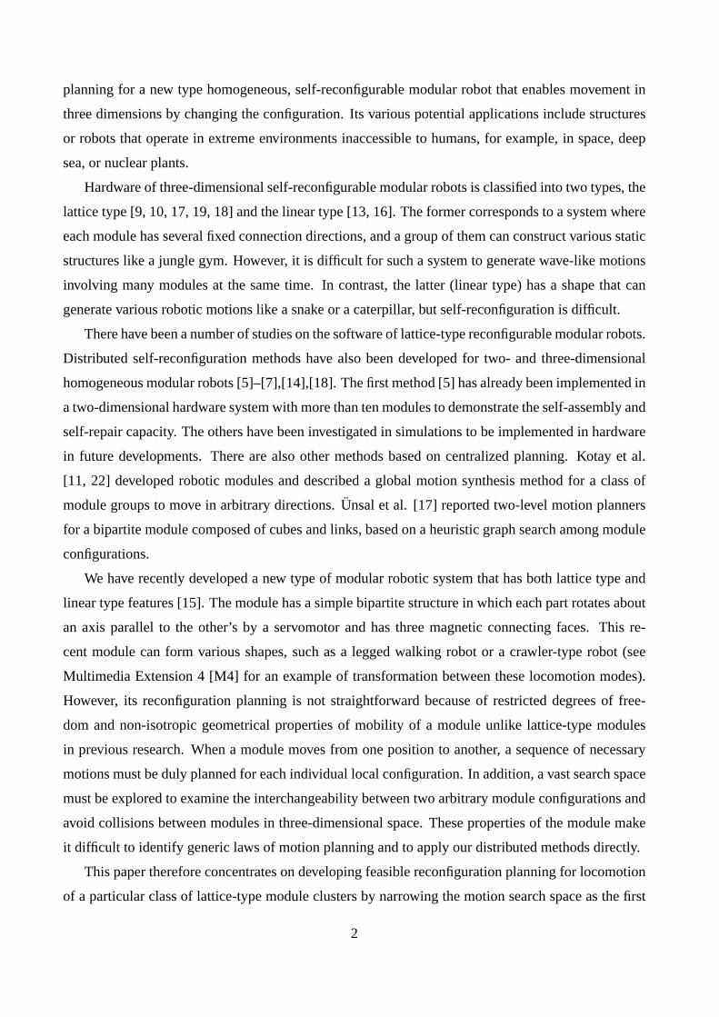
servo 1
servo 2
θ 2
p1p2
θ 1
magnetic connecting faces
Fig. 1: A robotic module [M1].
Strong rareearth magnets
Non-linearspring
Heating SMA Strong connection
Disconnectionwith small force
Active part
Passive part
Fig. 2: Connection mechanism [M1].
3

2 Hardware Design and Basic Motions
2.1 Hardware Overview
The developed module consists of two semi-cylindrical parts connected by a link part (Fig. 1). Servo-
motors are embedded in the link part so that each part can rotate by 180◦. The semi-cylindrical parts
of the module are labeled p1 and p2. The rotational angles of these parts (θ1, θ2) are limited to either
0◦ or ±90◦ for simplicity. The unit length of the lattice grid is defined as the length between the two
rotational axes of the module. A module therefore occupies two adjacent points in the grid.
Figure 3a shows the hardware of the prototype module. Each module has three surfaces to connect
with other modules, and the connecting mechanism is based on an “Internally-Balanced Magnetic
Unit” [20]. An active semi-cylindrical part (p1), which can be connected to only passive parts (p2)
of other modules, has nonlinear springs and shape memory alloy (SMA) springs whose compression
force is made slightly less than the magnetic force. By electrically heating the SMA springs, the total
force of springs becomes larger than the magnetic force and the connection is released, as shown in
Fig. 2 [15]. Figure 3b shows the internal structure of the module. The connecting surfaces also have
electrodes for power supply and serial communication. All the connected modules can be supplied
power from one module connected to the power source. This eliminates the tether entanglement that
becomes significant in three-dimensional configurations.
Each module is equipped with a PIC microprocessor BasicStamp II that drives servomotors and
SMA actuators. In the current development, all the modules are controlled from a host PC that
provides motion commands through serial communication bus lines. One semi-cylindrical part is
6cm cube, and a module weighs approximately 400g. The SMA actuator is controlled by 200Hz
PWM with a 60% duty ratio, 12V voltage and 2A average current.
Active Passive
Magnets
Serial Comm. GND12V
BasicStamp IIServomotors
Magnets
Nonlinersprings SMA
springs
(a) Hardware overview (b) Internal structure.
Fig. 3: Hardware module [M1].
4
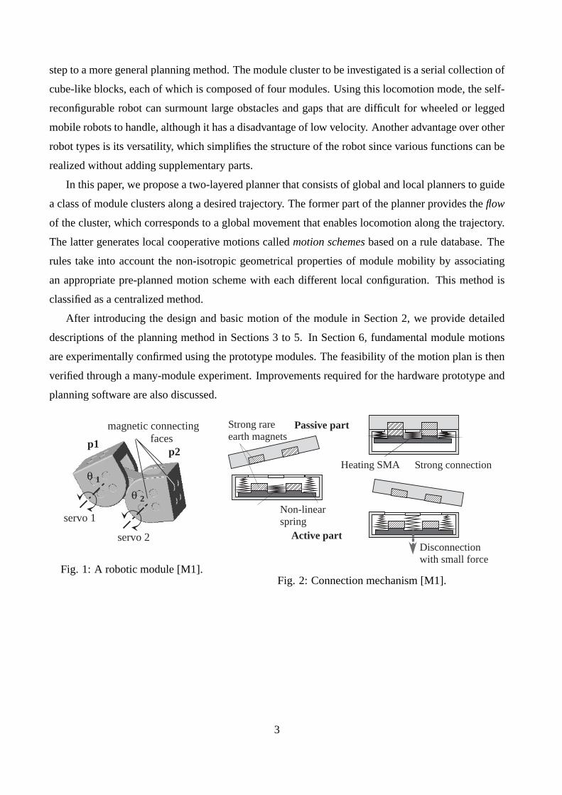
2.2 Atomic Motion
Before introducing the reconfiguration planner, it is helpful to explain the atomic motions that are
the simplest module motions of one or two modules. There are mainly three types of atomic motion,
pivot motion, forward-roll motion and mode conversion.
Figures 4 and 5 show two different atomic motions on a plane, forward-roll and pivot motions,
where the orientation of the rotational axes are different.
When a module makes a motion, one of the parts must be attached to another module, or fixed
part, to maintain connectivity. This fixed part is called a base part. Atomic motions are achieved by
alternating the base part properly. Here, the plane is also assumed to be filled by the connecting faces
of the module that performs appropriate connection and disconnection operations to realize these
motions. The module is said to be in pivot mode or forward-roll mode if it can perform one of these
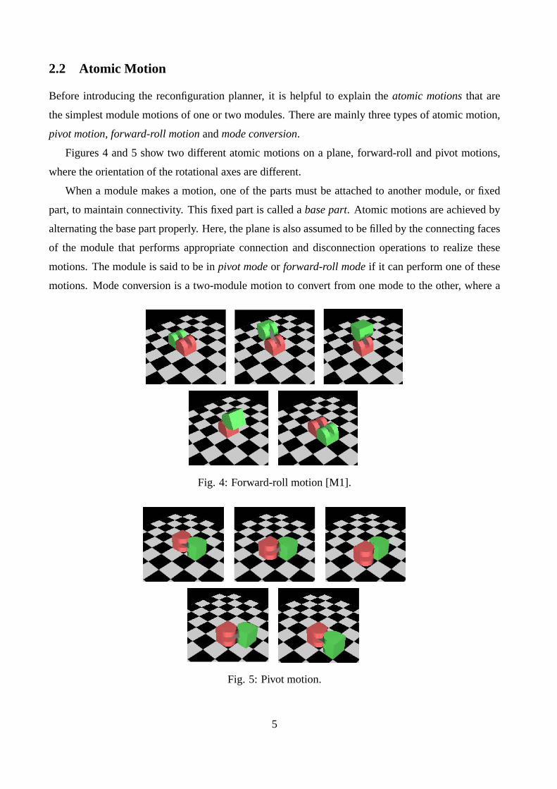
motions. Mode conversion is a two-module motion to convert from one mode to the other, where a
Fig. 4: Forward-roll motion [M1].
Fig. 5: Pivot motion.
5
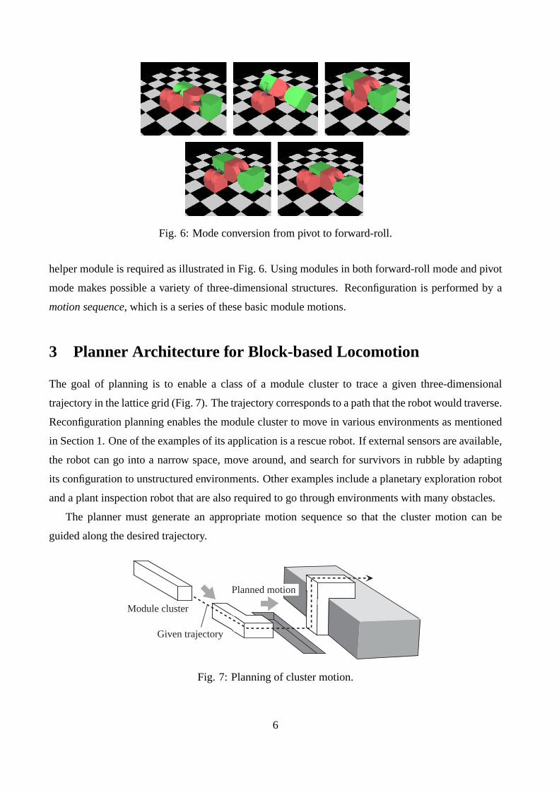
Fig. 6: Mode conversion from pivot to forward-roll.
helper module is required as illustrated in Fig. 6. Using modules in both forward-roll mode and pivot
mode makes possible a variety of three-dimensional structures. Reconfiguration is performed by a
motion sequence, which is a series of these basic module motions.
3 Planner Architecture for Block-based Locomotion
The goal of planning is to enable a class of a module cluster to trace a given three-dimensional
trajectory in the lattice grid (Fig. 7). The trajectory corresponds to a path that the robot would traverse.
Reconfiguration planning enables the module cluster to move in various environments as mentioned
in Section 1. One of the examples of its application is a rescue robot. If external sensors are available,
the robot can go into a narrow space, move around, and search for survivors in rubble by adapting
its configuration to unstructured environments. Other examples include a planetary exploration robot
and a plant inspection robot that are also required to go through environments with many obstacles.
The planner must generate an appropriate motion sequence so that the cluster motion can be
guided along the desired trajectory.
Given trajectory
Module cluster
Planned motion
Fig. 7: Planning of cluster motion.
6
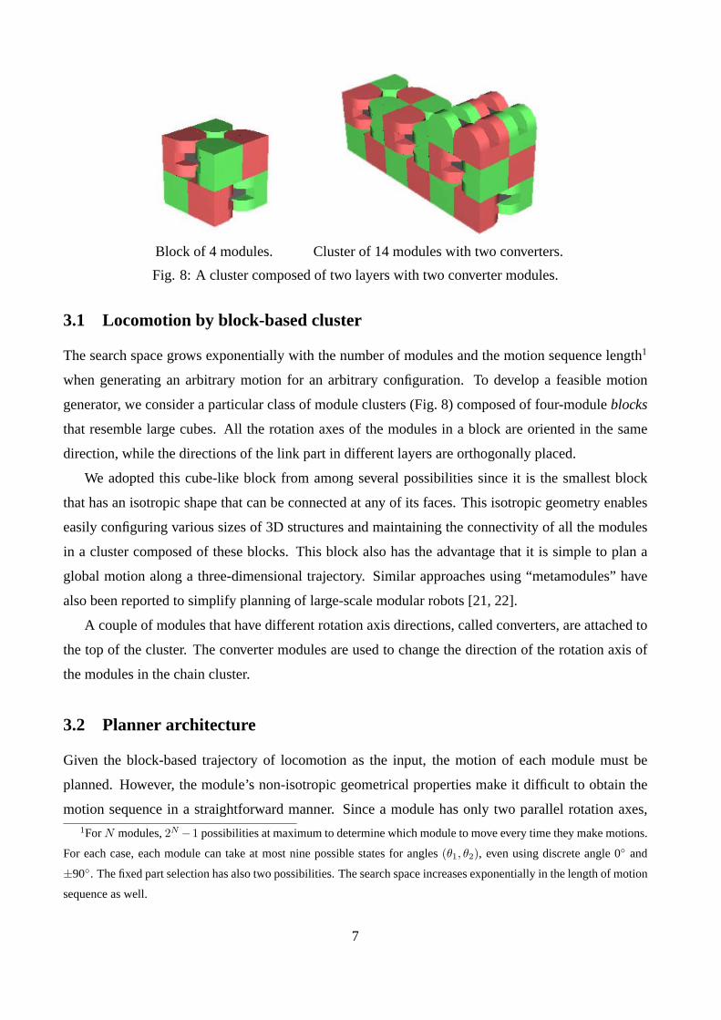
Block of 4 modules. Cluster of 14 modules with two converters.
Fig. 8: A cluster composed of two layers with two converter modules.
3.1 Locomotion by block-based cluster
The search space grows exponentially with the number of modules and the motion sequence length1
when generating an arbitrary motion for an arbitrary configuration. To develop a feasible motion
generator, we consider a particular class of module clusters (Fig. 8) composed of four-module blocks
that resemble large cubes. All the rotation axes of the modules in a block are oriented in the same
direction, while the directions of the link part in different layers are orthogonally placed.
We adopted this cube-like block from among several possibilities since it is the smallest block
that has an isotropic shape that can be connected at any of its faces. This isotropic geometry enables
easily configuring various sizes of 3D structures and maintaining the connectivity of all the modules
in a cluster composed of these blocks. This block also has the advantage that it is simple to plan a
global motion along a three-dimensional trajectory. Similar approaches using “metamodules” have
also been reported to simplify planning of large-scale modular robots [21, 22].
A couple of modules that have different rotation axis directions, called converters, are attached to
the top of the cluster. The converter modules are used to change the direction of the rotation axis of
the modules in the chain cluster.
3.2 Planner architecture
Given the block-based trajectory of locomotion as the input, the motion of each module must be
planned. However, the module’s non-isotropic geometrical properties make it difficult to obtain the
motion sequence in a straightforward manner. Since a module has only two parallel rotation axes,1For N modules, 2N −1 possibilities at maximum to determine which module to move every time they make motions.
For each case, each module can take at most nine possible states for angles (θ1, θ2), even using discrete angle 0◦ and
±90◦. The fixed part selection has also two possibilities. The search space increases exponentially in the length of motion
sequence as well.
7

its three-dimensional motion usually requires a combined cooperative motion sequence with other
surrounding modules. The cooperative motion sequence must be carefully chosen in each individual
local configuration to avoid collisions between modules or loss of connectivity during the motion.
Since generally applicable laws have not been determined yet for planning these motion sequences,
an available database of rules is necessary.
This paper proposes a two-layered motion planner consisting of the global flow planner and the
local motion scheme selector. As shown in Fig. 9, the global flow planner searches possible module
paths and motion orders to provide the global cluster movement, called flow, according to the desired
trajectory. This is realized as the motion of a block such that the tail block is transferred toward
the given heading direction. The local motion scheme selector verifies that the paths generated by
the global planner are valid for each member module of the block according to the possible motion
orders, by repeatedly applying rules from the database. The rule includes a local reconfiguration
motion sequence, called a motion scheme, associated with an individual initial local configuration.
If the given paths are validly determined for all the member modules in one of the motion orders,
the selector updates the reconfiguration plan by adding selected motion schemes from the database.
Otherwise, the selector tries the other possibilities generated by the global planner until a feasible plan
is determined. The selector copes with the non-isotropic properties of module mobility by associating
the cooperative motion with the corresponding local configuration in the form of rules. Note that this
is a centralized planning method that assumes all the information about the modules in the cluster is
available.
The method is scalable in the sense that planning of various length of cluster can be treated in the
same framework, although it applies only to these particular serial clusters composed of four-module
Global planner Locomotiontrajectory
Motion scheme selector
Target position of moving tail block
- motion order Candidate list
Rule database
if local configthen motion scheme
For each motion order:
- Verifies feasibility of pathsbased on rule database
for each module
- paths for each member module
Candidate list
Reconfiguration plan Add and update: New motion sequence
Input:
Output:Planning result:
Fig. 9: Reconfiguration planner architecture.
8
cubic blocks.
In the planning described below, we assume for simplicity that only one motion scheme is allowed
at a time and that the flow direction does not self-intersect and runs straight for at least two unit
lengths during the cluster flow. We also assume in the planning that one module can lift only one
other module, which comes from the limited torque capacity of the hardware.
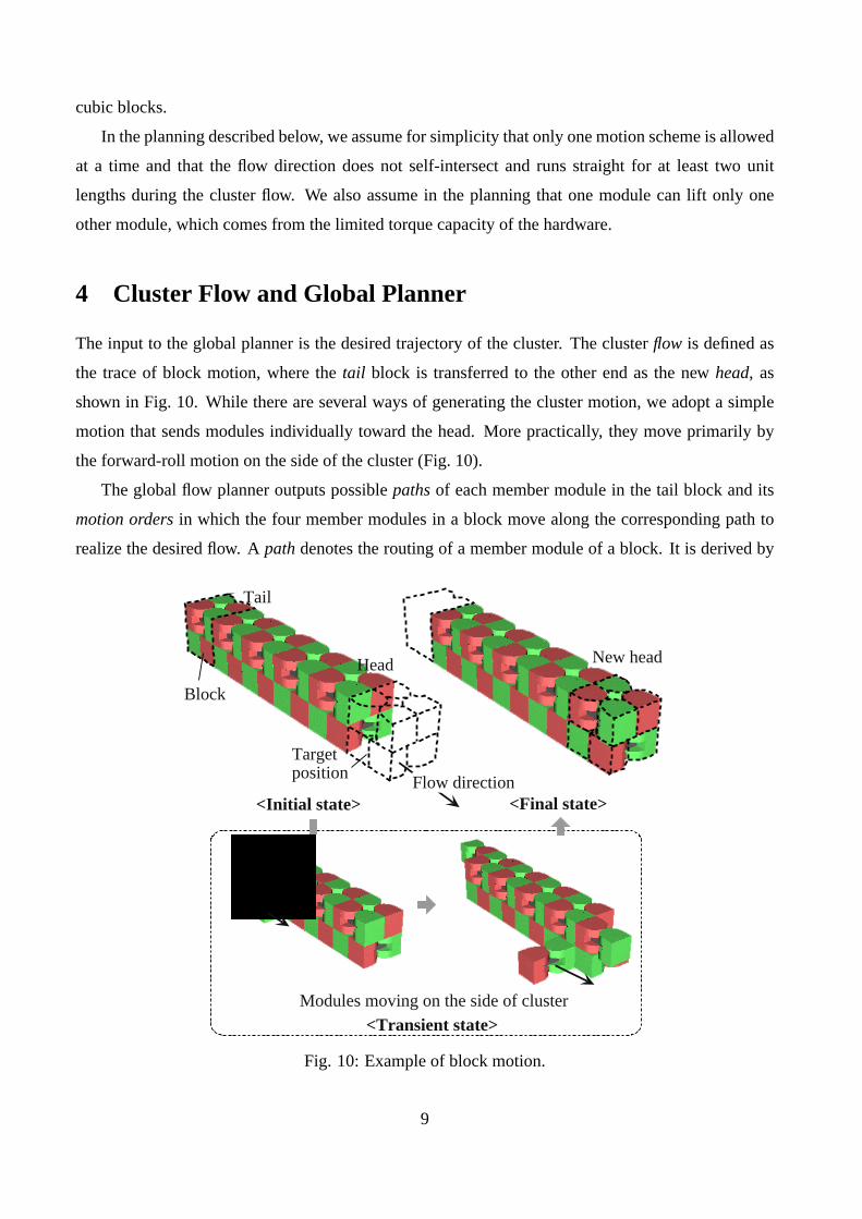
4 Cluster Flow and Global Planner
The input to the global planner is the desired trajectory of the cluster. The cluster flow is defined as
the trace of block motion, where the tail block is transferred to the other end as the new head, as
shown in Fig. 10. While there are several ways of generating the cluster motion, we adopt a simple
motion that sends modules individually toward the head. More practically, they move primarily by
the forward-roll motion on the side of the cluster (Fig. 10).
The global flow planner outputs possible paths of each member module in the tail block and its
motion orders in which the four member modules in a block move along the corresponding path to
realize the desired flow. A path denotes the routing of a member module of a block. It is derived by
Tail
Flow direction
New head
<Initial state> <Final state>
<Transient state>
Head
Modules moving on the side of cluster
Block
Targetposition
Fig. 10: Example of block motion.
9

tracing lattice positions on the side of the cluster, starting from the initial tail position, until the module
reaches one of the target positions next to the current head block. A module may have multiple target
positions and paths; their number varies depending on the cluster configuration. In Fig. 11 where
module 1 is moving, there are two possible paths to the two target positions. The tail block becomes
a new head block after it reaches the other end of the cluster. The next tail is then sent to the head,
and so forth.
The global planner also outputs the possible motion orders of applying paths. These orders must
be determined in such a way that the connectivity of whole cluster is maintained. For example,
consecutive transportation of modules 1 and 2 in Fig. 11 is not allowed because the connectivity of
the two lower modules is violated after the motion of the two modules.
5 Motion Scheme Selector
After the global planner outputs the possible motion orders and module paths, appropriate motion
schemes must be selected for the modules to achieve the paths to generate the reconfiguration plan.
The motion scheme selector plays this role by using the database of rules for local cooperative motion.
5.1 Selection overview
The selector outputs a reconfiguration plan as a unified motion sequence by collecting the motion
schemes selected based on the rule database, as described below. Each rule includes a motion scheme
associated with an initial configuration that is described as a connectivity graph. Here, the block
Path 1
Path 2goal points
p1 p2
path pointsp1 p2
Possible pathsPossible targetpositions
Flow direction
p1p2
2
1 21
(Moving)
Fig. 11: Path of a module for block motion.
10

movement is realized by the individual motion of each member module in a valid order; one module
continues to move until it reaches a target position.
(1) Selecting the motion order
A motion order in which all the member modules of the moving block have valid paths is
selected from among the possible motion orders.
If a feasible order is found, the selector can successfully output the reconfiguration plan.
(2) Verifying the valid paths
The possible paths for the moving module are examined to determine if they are sufficiently
valid to have a unified motion sequence that enables the module to reach the target position.
This verification is performed in increasing order of the path’s traveling distance; the path with
the shortest length is tried first; the second shortest, next; and so on.
This verification terminates successfully if a valid path is found for the moving module.
(3) Generating the unified motion scheme
The output unified motion sequence for the path is initialized as an empty sequence. The
following is repeated until the moving module reaches the target position along the examined
path, starting from the initial position.
(a) A list of all the rules that match the current local configuration of the moving module is
extracted from the rule database (Section 5.2).
(b) The rules in the list are screened by verifying the motion executability, taking into account
connectivity and collision avoidance (Section 5.3).
(c) A rule that gives the maximum forward movement along the path is selected from among
the listed rules.
The motion scheme associated with the selected rule is added to the unified motion se-
quence. The position of the moving module is also updated accordingly.
If no rules are found, the selection process continues by using a backtracking search.
If the module arrives at the target position, a unified motion sequence is successfully generated
for the path.
If the above verification is successful, the unified motion sequence is determined for the moving
block and is added to the total reconfiguration plan; otherwise the planning fails. Sufficient rules
must therefore be provided to appropriately generate the reconfiguration plan.
Concerning the computational complexity, the most time-consuming part is the backtracking
search during generation of the unified motion scheme. However, the search space can be sufficiently
narrowed based on careful rule definition and the heuristics selecting the rules giving the maximum
11
movement along the path. In most cases, the planner can retrieve one best-fitting rule at each position
in the path. The computational time, therefore, becomes almost linear to the numbers of modules and
rules.
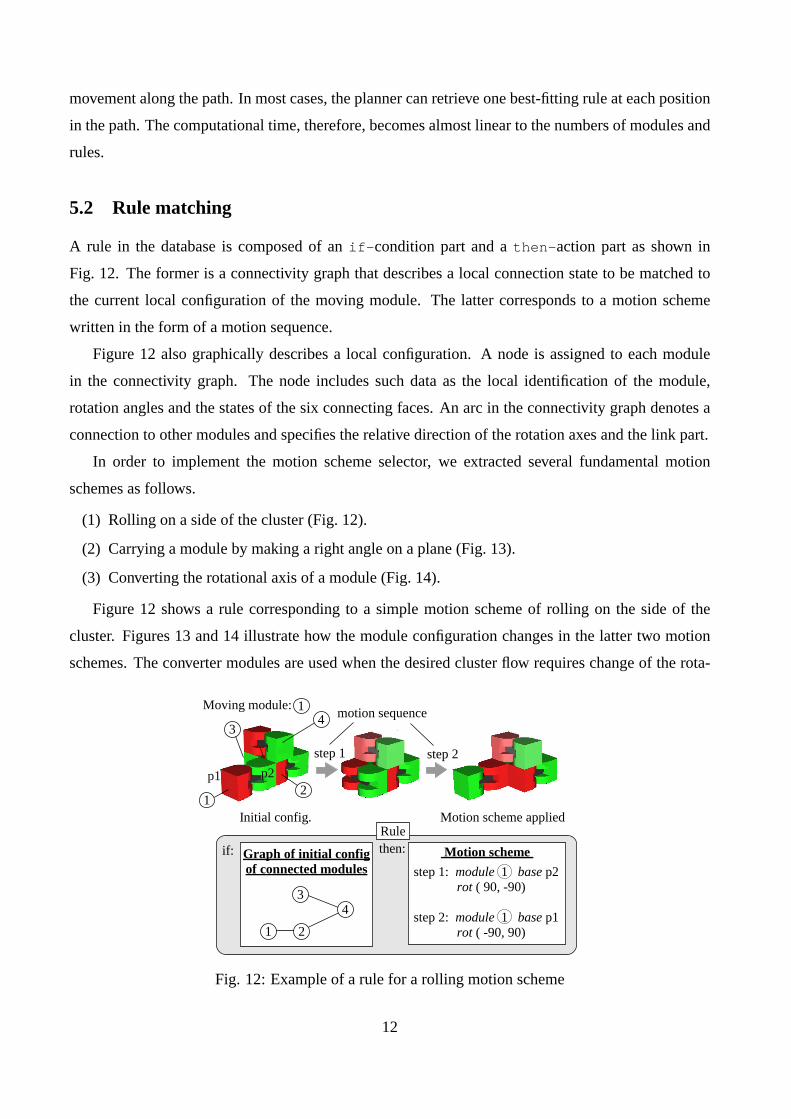
5.2 Rule matching
A rule in the database is composed of an if-condition part and a then-action part as shown in
Fig. 12. The former is a connectivity graph that describes a local connection state to be matched to
the current local configuration of the moving module. The latter corresponds to a motion scheme
written in the form of a motion sequence.
Figure 12 also graphically describes a local configuration. A node is assigned to each module
in the connectivity graph. The node includes such data as the local identification of the module,
rotation angles and the states of the six connecting faces. An arc in the connectivity graph denotes a
connection to other modules and specifies the relative direction of the rotation axes and the link part.
In order to implement the motion scheme selector, we extracted several fundamental motion
schemes as follows.
(1) Rolling on a side of the cluster (Fig. 12).
(2) Carrying a module by making a right angle on a plane (Fig. 13).
(3) Converting the rotational axis of a module (Fig. 14).
Figure 12 shows a rule corresponding to a simple motion scheme of rolling on the side of the
cluster. Figures 13 and 14 illustrate how the module configuration changes in the latter two motion
schemes. The converter modules are used when the desired cluster flow requires change of the rota-
1 2
34
Initial config.
Graph of initial configof connected modules
\
Rule
if: then: Motion scheme
step 1: module 1 base p2 rot ( 90, -90)
step 2: module 1 base p1 rot ( -90, 90)
p1 p2
12
34
step 1 step 2
motion sequence
Motion scheme applied
Moving module: 1
Fig. 12: Example of a rule for a rolling motion scheme
12

Moving
x y
Module path
Flow direction
Helper module
Fig. 13: Direction change of cluster on a plane.
Moving
x y
Module path
Flow direction
ConverterModule
Fig. 14: Direction change to vertical direction on a plane.
tional axes of the modules (Fig. 14). The number of converter modules can be augmented if necessary.
Some 30 basic rules have been extracted as basic motion schemes and are currently hand-coded.
To find a motion scheme of the moving module for the path and motion order, the selector searches
for rules that match the current local configuration of the module. The selector then makes a list of
all the matching rules that will be verified by the motion executability test described below.
5.3 Motion executability test
The motion executability check is performed for each matched rule from two aspects, collision avoid-
ance and connectivity of the total cluster. If the latter is not satisfied, the cluster may be split into
two or more smaller clusters, which may cut off the communication and power supply. Applying the
motion scheme to the moving module enables a collision to be detected by calculating the sweeping
area of its motions. Similarly, the connectivity during the motion is examined by tracing the current
connectivity graph from the moving module down to connected modules.
When more than one rule is found valid, the rule that gives the maximum forward movement
along the path is selected. This avoids infinite motion loops that make the modules move back and
forth in the same place.
5.4 Planning results and discussions
The reconfiguration planner can generate three-dimensional paths for various sizes of clusters. Fig-
ure 15 shows some snapshots taken from the planned motion of a cluster of 22 modules starting from
13

x y
z
Desired flowdirection
Current direction
90 horizontal
90 vertical
Fig. 15: Simulated plan of motions in different flow directions from initial configuration on a plane
[M2].
a configuration on a plane. The cluster first changes its flow direction in the horizontal plane, then
moves in a vertical direction. The cluster traveled by 16 unit lengths along the flow trajectory, and the
resulting motion sequence takes 773 steps.
Although the currently developed method applies to a limited class, we believe that the basic
framework of the two-layered approach is generally effective for other classes. The global planner
depends largely on the application and should be designed to narrow the search space according to
the task. In contrast, the motion scheme selector is less problem-dependent owing to its locality.
It is applicable to various classes of module structures provided that basic rule sets that can cover
sufficiently wide cases are correctly extracted. We are thinking of extending the database using an
evolutionary method, and also generating more complex rules including rule hierarchy.
Simultaneous motion of several modules is another important issue for overcoming the low ve-
locity of the cluster motion. This improvement is being implemented to increase the concurrency of
motion by parallelizing several concurrent motion sequences. Future work also includes trajectory
planning and extension of the planning method for more complicated paths, as well as theoretical
investigation of completeness and optimality.
14

6 Hardware Experiments
A hardware prototype of the robotic modules is currently under development. After the basic atomic
motions of modules are verified, an example of the cluster motion of a block structure will be imple-
mented to show the planned motion can be achieved by hardware modules.
6.1 Atomic Motions
Figures 16 to 18 show the experiments of the forward-roll motion (Fig. 4), pivot motion (Fig. 5), and
mode conversion (Fig. 6). In these experiments, the connecting mechanism performed reliably; it
is strong enough to hold the module against gravity and detaches smoothly. It takes approximately
five seconds for the connection to be completely released, mainly due to the time required to heat
the SMAs. We also verified from Fig. 18 that the module has sufficient torque to conduct certain
two-module motions.
Fig. 16: Experiment of forward-roll motion.
Fig. 17: Experiment of pivot motion.
Fig. 18: Experiment of mode conversion.
15

6.2 Block Cluster Locomotion
The planned cluster motion experiment described in this paper has been conducted using the hardware
modules. The motion is planned in the host PC and then converted into low-level control commands of
servomotors and SMA actuators by the simulator software. These control commands are distributed
to the microprocessor of appropriate modules through a serial bus line by way of electrodes on the
connecting faces. The commands are sent with module IDs so the indicated modules can achieve the
desired motion. Power is also supplied to all the modules through inter-module connection from one
module connected to the power source.
In this experiment, eight-module cluster flow motion is executed. Although the generated motion
plan transfers the modules individually on the side of the cluster, the plan was modified so that some
motions are carried out in parallel to reduce the execution time. There was a total of 23 motion steps.
As shown in Fig. 19, cluster motion has been achieved, demonstrating the validity of the planned
motion.
These experiments have suggested several issues to be improved in future hardware developments.
Redesigning electrodes. During the pivot motion (Fig. 5), there is sometimes an unnecessary contact
between the electrodes. The next prototype model will be improved by allowing the electrodes
to slide with the connecting mechanism to prevent such unfavorable effects.
Providing sensors for modules. By measuring the internal state and detecting the external environ-
ment, the group of modules will be able to adapt to various situations. For this purpose, we
intend to use inclinometers and tactile sensors in the next prototype.
Flow direction
Target positions
Initial state step 4 after step 8 step 14
after step 17 after step 18 after step 21 Final state
Fig. 19: Experiment of cluster motion of block structure using 8 modules [M3].
16

Planning for efficient motions. Plans that require more disconnection operations consume more
time for motion, even though the difference is not apparent in the current simulator. This
cost should be reflected in planning and rule definition to generate more efficient motion by the
hardware module. Simultaneous module motion is another issue to be addressed for efficient
module motion as previously mentioned.
7 Conclusions
This paper discussed the reconfiguration planning for locomotion of a self-reconfigurable modular
robot and conducted experiments of the planned locomotion. A module was designed to generate
three-dimensional structures of both the lattice and linear types. A two-layered planning method was
proposed for a class of three-dimensional structures composed of multi-module blocks. The global
flow planner outputs possible paths and motion orders to realize the block-based cluster flow. The
local motion scheme selector determines the motion of each module according to the output from the
global planner. The non-isotropic geometric properties of module mobility were properly reflected
in the rules that associate appropriate pre-planned motions with corresponding local configurations.
The future work concerning the reconfiguration planner includes investigation of more complete and
compact rule sets applicable to wider classes of configurations. Generating simultaneous motion of
many modules is also an important issue to be investigated to fully exploit the parallelism of the
modular robot and to improve the locomotion velocity. Theoretical completeness and optimality of
the method must also be addressed in the future work.
Several experiments were performed to verify the fundamental atomic motions and to show the
feasibility of the generated plans using the prototype modules. From these experiments, we could
obtain feedback to the planner in order to improve the efficiency of the motion by the hardware
module. The basic module functions have now been confirmed. In the next development stage, we
will seek to improve some mechanisms for motion reliability and to provide sensors for modules.
This will allow the module cluster to move around in unknown environments with bumps or walls,
adapting its shape to the outside world.
Multimedia Index Table
The multimedia extension page is found at http://www.ijrr.org.
17
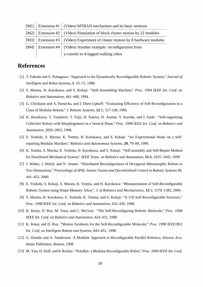
[M1] Extension #1 (Video) MTRAN mechanism and its basic motions
[M2] Extension #2 (Video) Simulation of block cluster motion by 22 modules
[M3] Extension #3 (Video) Experiment of cluster motion by 8 hardware modules
[M4] Extension #4 (Video) Another example: reconfiguration from
a crawler to 4-legged walking robot
References
[1] T. Fukuda and S. Nakagawa: “Approach to the Dynamically Reconfigurable Robotic System,” Journal of
Intelligent and Robot Systems, 1, 55–72, 1988.
[2] S. Murata, H. Kurokawa, and S. Kokaji: “Self-Assembling Machine,” Proc. 1994 IEEE Int. Conf. on
Robotics and Automation, 441–448, 1994.
[3] G. Chirikjian and A. Pamecha, and I. Ebert-Uphoff: “Evaluating Efficiency of Self-Reconfiguration in a
Class of Modular Robots,” J. Robotic Systems, 12-5, 317-338, 1996.
[4] K. Hosokawa, T. Tsujimori, T. Fujii, H. Kaetsu, H. Asama, Y. Kuroda, and I. Endo: “Self-organizing
Collective Robots with Morphogenesis in a Vertical Plane,” Proc. 1998 IEEE Int. Conf. on Robotics and
Automation, 2858–2863, 1998.
[5] E. Yoshida, S. Murata, K. Tomita, H. Kurokawa, and S. Kokaji: “An Experimental Study on a Self-
repairing Modular Machine,” Robotics and Autonomous Systems, 29, 79–89, 1999.
[6] K. Tomita, S. Murata, E. Yoshida, H. Kurokawa, and S. Kokaji: “Self-assembly and Self-Repair Method
for Distributed Mechanical System,” IEEE Trans. on Robotics and Automation, 15-6, 1035–1045, 1999.
[7] J. Walter, J. Welch, and N. Amato: “Distributed Reconfiguration of Hexagonal Metamorphic Robots in
Two Dimensions,” Proceedings of SPIE, Sensor Fusion and Decentralized Control in Robotic Systems III,
441–453, 2000.
[8] E. Yoshida, S. Kokaji, S. Murata, K. Tomita, and H. Kurokawa: “Miniaturization of Self-Reconfigurable
Robotic System using Shape Memory Alloy,”, J. of Robotics and Mechatronics, 12-2, 1579–1585, 2000.
[9] S. Murata, H. Kurokawa, E. Yoshida, K. Tomita, and S. Kokaji: “A 3-D Self-Reconfigurable Structure,”
Proc. 1998 IEEE Int. Conf. on Robotics and Automation, 432–439, 1998.
[10] K. Kotay, D. Rus, M. Vona, and C. McGray: “The Self-Reconfiguring Robotic Molecule,” Proc. 1998
IEEE Int. Conf. on Robotics and Automation, 424–431, 1998.
[11] K. Kotay and D. Rus: “Motion Synthesis for the Self-Reconfigurable Molecule,” Proc. 1998 IEEE/RSJ
Int. Conf. on Intelligent Robots and Systems, 843–851, 1998.
[12] G. Hamlin and A. Sanderson: A Modular Approach to Reconfigurable Parallel Robotics, Kluwer Aca-
demic Publishers, Boston, 1998.
[13] M. Yim, D. Duff, and K Roufas: “PolyBot: a Modular Reconfigurable Robot,” Proc. 2000 IEEE Int. Conf.
18

on Robotics and Automation, 514–520, 2000.
[14] E. Yoshida, S. Murata, H. Kurokawa, K. Tomita, and S. Kokaji: “A Distributed Method for Reconfigura-
tion of 3-D homogeneous structure,” Advanced Robotics, 13-4, 363–380, 1999.
[15] S. Murata, E. Yoshida, K. Tomita, H. Kurokawa, A. Kamimura, and S.Kokaji: “Hardware Design of
Modular Robotic System,” Proc. 2000 IEEE/RSJ Int. Conf. on Intelligent Robots and Systems, F-AIII-3-
5, 2000.
[16] A. Castano, R. Chokkalingam, and P. Will: “Autonomous and Self-Sufficient CONRO Modules for Re-
configurable Robots,” Distributed Autonomous Robotics 4, Springer, 155–164, 2000.
[17] C. Unsal, H. Kılıccote, and P. Khosla: “A modular self-reconfigurable bipartite robotic system: Imple-
mentation and Motion Planning,” Autonomous Robots, 10-1, 23–40, 2001.
[18] M. Yim, Y. Zhang, J. Lamping, and E. Mao: “Distributed Control for 3D Metamorphosis,” Autonomous
Robots 10-1, 41–56, 2001.
[19] D. Rus and M. Vona. “Crystalline Robots: Self-reconfiguration with Compressible Unit Modules,” Au-
tonomous Robots, Vol.10-1, 107–124, 2001.
[20] S. Hirose, M. Imazato, Y. Kudo, and Y. Umetani: “Internally-balanced Magnetic Unit,” Advanced
Robotics, 3-4, 225–242, 1986.
[21] A. Nguyen, L. Guibas, and M. Yim: “Controlled Module Density Helps Reconfiguration Planning”,
Workshop on Algorithmic Foundations of Robotics (WAFR), 23–35, 2000.
[22] K. Kotay and D. Rus: “Scalable parallel algorithm for configuration planning for self-reconfiguring
robots,” Proceedings of SPIE, Sensor Fusion and Decentralized Control in Robotic Systems III, 2000.
19