A SECURITY ARCHITECTURE FOR NET-CENTRIC ENTERPRISE...
75
A SECURITY ARCHITECTURE FOR NET-CENTRIC ENTERPRISE SERVICES (NCES) Version 0.3 (Pilot) Defense Information Systems Agency (DISA) March 1, 2004
Transcript of A SECURITY ARCHITECTURE FOR NET-CENTRIC ENTERPRISE...
A SECURITY ARCHITECTURE FOR
NET-CENTRIC ENTERPRISE SERVICES (NCES)
Version 0.3 (Pilot)
Defense Information Systems Agency (DISA)
March 1, 2004
NCES Security Services Architecture
Version 0.3 ii February 20, 2004
Document Change Record
Version Date Description NCES v0.3 03-Mar-2004 First public release

NCES Security Services Architecture
Version 0.3 iii February 20, 2004
Table of Contents
1. EXECUTIVE SUMMARY ...................................................................................................1
2. NOTATIONS AND TERMINOLOGY ................................................................................2 2.1 Notations .......................................................................................................................2 2.2 Terminology ..................................................................................................................2
3. BACKGROUND ...................................................................................................................4 3.1 Service Oriented Architectures ......................................................................................4 3.2 Net-Centric Enterprise Services (NCES) ........................................................................6 3.3 Overview of XML Security Standards.............................................................................7
4. ARCHITECTURE OVERVIEW .......................................................................................10 4.1 Security Challenges under SOAs..................................................................................10 4.2 Summary of Architectural Requirements ......................................................................12 4.3 Scope, Assumptions, and Limitations ...........................................................................14 4.4 Conceptual Enterprise Security Architecture ...............................................................15 4.5 The Security CESs .......................................................................................................17
5. THE TRUST MODEL ........................................................................................................23 5.1 The Micro View ...........................................................................................................23 5.2 The Macro View ..........................................................................................................25
6. SECURITY ARCHITECTURE WITHIN A TRUST DOMAIN ......................................28 6.1 Securing the Invocation Path .......................................................................................28 6.2 Service Chaining .........................................................................................................32
7. AUTHENTICATION..........................................................................................................35 7.1 Asserting the Authentication of End Users ...................................................................35 7.2 SOAP Message Authentication.....................................................................................37
8. AUTHORIZATION ............................................................................................................42 8.1 Authorization Architecture...........................................................................................42 8.2 Two Approaches for Making Policy Decisions .............................................................44 8.3 Policy Decision Implementation Considerations ..........................................................46
9. AUTHORIZATION POLICIES.........................................................................................48 9.1 The RBAC Model.........................................................................................................48 9.2 Looking Ahead: the Attribute Based Approach.............................................................51
10. OTHER TOPICS...............................................................................................................53 10.1 Message Confidentiality.............................................................................................53 10.2 Use of DoD PKI.........................................................................................................53 10.3 Beyond Trust Domain Boundaries .............................................................................56
11. FUTURE WORK ..............................................................................................................58
NCES Security Services Architecture
Version 0.3 iv February 20, 2004
A. MESSAGE EXAMPLES....................................................................................................61 A.1 SAML Assertion Element Created by Portal ................................................................61 A.2 Signed SOAP Request..................................................................................................61 A.3 SAML-P Authorization Decision Query .......................................................................63 A.4 SAML-P Authorization Decision Response ..................................................................64 A.5 XACML Policy Set.......................................................................................................64
B. REFERENCES ...................................................................................................................69

NCES Security Services Architecture
Version 0.3 v February 20, 2004
List of Figures FIGURE 1 - SERVICE ORIENTED ARCHITECTURE............................................................................4 FIGURE 2 - UNDERLYING SECURITY TECHNOLOGY STACK ............................................................8 FIGURE 3 - CONCEPTUAL ENTERPRISE SECURITY ARCHITECTURE ...............................................16 FIGURE 4 – THE MICRO VIEW: WITHIN A SINGLE TRUST DOMAIN...............................................24 FIGURE 5 – THE MACRO VIEW: ACROSS TRUST DOMAIN BOUNDARIES .......................................26 FIGURE 6 - LOGICAL SECURITY ARCHITECTURE, SINGLE TRUST DOMAIN....................................28 FIGURE 7 - CHAINING OF INBOUND MESSAGE HANDLERS............................................................30 FIGURE 8 - SERVICE CHAINING...................................................................................................33 FIGURE 9 - MESSAGING TERMS ..................................................................................................35 FIGURE 10 - MESSAGE AUTHENTICATION ...................................................................................38 FIGURE 11 - SIGNED SOAP MESSAGE ........................................................................................39 FIGURE 12 - AUTHORIZATION ARCHITECTURE ............................................................................43 FIGURE 13 - BASIC RBAC MODEL.............................................................................................49 FIGURE 14 - RBAC BASED POLICIES..........................................................................................51
List of Tables TABLE 1 - CURRENTLY SUPPORTED STANDARDS AND THEIR VERSIONS.........................................9 TABLE 2 - SECURITY CES TAXONOMY.......................................................................................18

NCES Security Services Architecture
Version 0.3 1 February 20, 2004
1. EXECUTIVE SUMMARY 1
The emergence of Web Service technologies has triggered a major paradigm shift in 2 distributed computing: from Distributed Object Architectures (DOAs) to Service 3 Oriented Architectures (SOAs). Within the Department of Defense (DoD) Enterprise 4 there has been a growing need for increased integration and collaboration among 5 “Communities of Interest” (COIs), often across organizational boundaries. The DoD 6 transformation towards Net-Centricity highlights the need even further. A common set 7 of Core Enterprise Services (CESs) represent crucial infrastructure components that 8 support this vision. SOAs are well positioned to become the key technology enabler for 9 Net-Centricity due to their decentralized, loosely coupled, and highly interoperable 10 architecture. Securing a SOA, however, faces new challenges that cannot be fully 11 addressed by existing Information Assurance solutions. This document describes the 12 drivers, challenges, and requirements for securing a SOA in the Net-Centric 13 environment, and proposes a security architecture that meets the unique burden of 14 securing a decentralized system. 15 16 This document presents the high-level reference architecture, and defines an abstract 17 “Security CES” layer that encapsulates enterprise security functionality such as 18 authorization and credential management. To help secure Net-Centric interactions 19 among enterprise service consumers and providers, the Security CESs themselves are 20 defined as Web Services that are standards-based, platform-independent, and 21 technology-neutral. The document also introduces the concepts of an indirect or 22 “brokered” trust model, and argues that such a trust model is necessary to support an 23 environment involving decentralized, heterogeneous security infrastructure and 24 policies. 25 26 The architecture is then described in detail, along with guidance for how such an 27 architecture can be constructed using emerging industry standards such as WS-28 Security, SAML, XACML, and XML Digital Signatures. More importantly, this 29 document defines additional processing rules that “profile” these standards for use in a 30 DoD Enterprise environment. These processing rules allow the security architecture to 31 achieve interoperability while leveraging an underlying foundation of DoD Enterprise 32 security infrastructure such as Identity Management and PKI. 33 34 Just like the Web Service technologies it leverages, the security architecture presented in 35 this document is still in its infancy. Some potential future work items are listed at the 36 end of the document, and it is expected that the scope of this document will grow over 37 time. 38
39

NCES Security Services Architecture
Version 0.3 2 February 20, 2004
2. NOTATIONS AND TERMINOLOGY 39
2.1 Notations 40
The key words "MUST", "MUST NOT", "REQUIRED", "SHALL", "SHALL NOT", 41 "SHOULD", "SHOULD NOT", "RECOMMENDED", "MAY", and "OPTIONAL" in this 42 document are to be interpreted as described in IETF RFC 2119 [RFC 2119]. E.g.: 43
… they MUST only be used where it is actually required for 44 interoperation or to limit behavior which has potential for causing 45 harm (e.g., limiting retransmissions) … 46
These keywords are thus capitalized when used to unambiguously specify 47 requirements over protocol and application features and behavior that affect the 48 interoperability and security of implementations. When these words are not capitalized, 49 they are meant in their natural-language sense. 50 51 Fixed width texts used for file names, constants, <XML elements>, and code 52 examples. 53 54
Example code listings appear like this. 55 56 Italics texts are used for variables and other type of entities that can change. Italics are 57 sometimes also used for emphasized text or annotations. 58 59 Terms in italic bold face are intended to have the meaning defined in the glossary. 60 61 Underlined texts are used for URLs. 62 63 2.2 Terminology 64
The following terms are frequently used in this document and are briefly explained 65 below using commonly accepted definitions in the security literature. The reference 66 section contains a number of security related glossaries that are much more 67 comprehensive [RFC2828] [WS-GLOS]. 68 69 Identity: A set of attributes that uniquely identifies a system entity such as a person, an 70 organization, a service, or a device. 71
Comment: Note that identities are not just for human users. Resources such as data 72 providers and service providers may also have their own identities. Also note that an 73 entity may have multiple identities (e.g. local, legal, organizational). 74
Identifier: A sufficiently unambiguous reference to an identity of a system entity. 75
Comment: Note the difference between an identity and an identifier. 76
Credential: A.k.a. Authentication Credential, data that is required to demonstrate the 77 possession of something in order to establish a claim. 78

NCES Security Services Architecture
Version 0.3 3 February 20, 2004
Comment: Credentials may be symmetric information (e.g. password, shared secret key, 79 or biometrics) or asymmetric information (e.g. private and public keys). An identity may 80 have more than one set of credentials. For example, a user may have a login/password, a 81 digital certificate, and his/her biometrics as credentials. 82
Principal: A Principal is an entity that has a network identity (see below), that is 83 capable of making decisions, and to which authenticated actions are done on its behalf. 84 A principal may refer to human entities such as an individual user, an organization, or a 85 legal entity; depending on the context it may also refer to non-human system entities 86 such as a Web Service provider. 87
Comment: This document makes a distinction between Principals and Identities. A 88 principal may have multiple local identities in different Administrative Domains. For 89 example, a user principal can have a work account called “JDoe” in his employer’s 90 network, and also a personal account called “John_Doe” issued by his Internet Service 91 Provider (ISP). 92
Please note that this document deliberately chooses not to use the term Subject due to its 93 overloaded meanings in different contexts. 94
Network Identity: The abstraction of the global set of attributes composed from a 95 Principal’s existing accounts. 96
Comment: “Network Identity” and “Principal” are used interchangeably in this 97 document, in that both of them denote an abstract “global identity” that consists of / 98 maps to a “local identity” in a specific security domain. 99
Trust Domain: This document defines a Trust Domain (TD) as a purely logical construct 100 within which a single set of access control policies hold. 101
Comment: This document deliberately chooses not to use the term Security Domain to 102 refer to a Trust Domain, due to its overloaded meanings and the often confusion with 103 Administrative Domains. A Trust Domain has nothing to do with administrative or 104 network security boundaries. In fact, multiple TDs may reside in a single administrative 105 domain. 106
Service Provider: A system entity that serves as a logical “container” of one or more 107 Web Service applications. A service provider may host one or more Web Services, and 108 may consist of one or many physical machines. If necessary, a service provider may be 109 assigned its own network identity and thus be considered a principal. 110
Service Consumer: A system entity that issues service requests and consumes returned 111 information. Within a SOA, a service consumer is usually an application. 112
Comment: A service provider may be a consumer of other service providers. 113
114 115

NCES Security Services Architecture
Version 0.3 4 February 20, 2004
3. BACKGROUND 115
3.1 Service Oriented Architectures 116
The emergence of Web Service* (WS) technologies has triggered a major paradigm shift 117 in distributed computing. Architectures are quickly moving from DOAs using 118 technologies such as CORBA, DCOM, DCE, and Java RMI, to SOAs using technologies 119 such as SOAP, HTTP and XML. Under a SOA, a set of network-accessible operations 120 and associated resources are abstracted as a “service”. The service is described in a 121 standard fashion, published to a service registry, discovered by a service consumer, and 122 invoked by a service consumer. Figure 1 illustrates the three steps of Publish, Discover 123 and Invoke. 124 125
SecurityServices
MonitoringServices
ServiceRegistries
MessagingServices
DataServices
TransformationServices
Service Enabled InfrastructurePublish
Data and applications available for use, accessible via services. Metadata added to services based on producer’s format.
Service Producer
• Describes content using metadata• Posts metadata in catalogs for discovery• Exposes data and applications as services
Discover
Invoke
Automated search of data services using metadata. Pulls data of interest. Based on producer registered format and definitions, translates into needed structure.
Service Consumer
• Searches metadata catalogs to find data services
• Analyzes metadata search results found• Pulls selected data based on metadata
understanding
SecurityServices
MonitoringServices
ServiceRegistries
MessagingServices
DataServices
TransformationServices
Service Enabled Infrastructure
SecurityServices
MonitoringServices
ServiceRegistries
MessagingServices
MessagingServices
DataServices
DataServices
TransformationServices
Service Enabled InfrastructurePublishPublish
Data and applications available for use, accessible via services. Metadata added to services based on producer’s format.
Service Producer
• Describes content using metadata• Posts metadata in catalogs for discovery• Exposes data and applications as services
Data and applications available for use, accessible via services. Metadata added to services based on producer’s format.
Service Producer
• Describes content using metadata• Posts metadata in catalogs for discovery• Exposes data and applications as services
DiscoverDiscover
InvokeInvoke
Automated search of data services using metadata. Pulls data of interest. Based on producer registered format and definitions, translates into needed structure.
Service Consumer
• Searches metadata catalogs to find data services
• Analyzes metadata search results found• Pulls selected data based on metadata
understanding
126 Figure 1 - Service Oriented Architecture 127
128 Three basic standards serve as the foundation of the Web Services protocol “stack”: 129
130 Simple Object Access Protocol (SOAP) [SOAP] performs the low-level XML 131
communications necessary for transmitting Web Service calls across the network. 132 *This architecture document refers to Web Services (with capital letters) as services using industry-accepted Web Service
technology standards such as SOAP, WSDL, and UDDI, as opposed to general services offered over the Web.

NCES Security Services Architecture
Version 0.3 5 February 20, 2004
SOAP provides a means of XML-based messaging between a service provider 133 and a service consumer. 134 135 Web Service Definition Language (WSDL) [WSDL] is an XML-based language 136
that defines the functional interfaces for a Web Service. In other words, a WSDL 137 document represents the official “contract” between service providers and their 138 consumers. These WSDL interfaces are described first in abstract message 139 structures, and then bound to a concrete transport protocol and a communication 140 “endpoint”. 141 142 Universal Discovery, Description, and Integration (UDDI) [UDDI] is an 143
emerging standard for organizing and accessing a service registry (see Figure 1). 144 A service registry serves as the yellow pages of a collection of Web Services, 145 providing mechanisms for a service provider to publish its capabilities and for a 146 service user to discover matching services. 147
148 A SOA offers several distinct advantages over traditional distributed computing 149 technologies: 150 151
Maximum Interoperability – The W3C and OASIS, among others, are currently 152 defining Web Service standards that are entirely based on XML. This ensures 153 that the standards are programming language-, platform-, and programming 154 model-neutral. For example, a .NET Web Service client written in the procedural 155 model of Visual Basic can readily invoke an Object-Oriented Web Service hosted 156 by a Java 2 Enterprise Edition (J2EE) server on a Linux machine. 157 158 Loose Coupling – Web Service standards define the functional interfaces that 159
represent the minimal understanding between service consumer and service 160 provider. Knowledge of the service provider is discovered dynamically from a 161 service registry rather than statically coded in the client program. 162 163 Ubiquity – Web Service calls are essentially XML messages sent over well-164
understood Internet protocols such as HTTP. These protocols represent the “least 165 common denominator” of network protocol stacks and makes it easier to 166 overcome firewall and infrastructure constraints. Web Services are likely to be 167 the most viable option for inter-agency information sharing among different 168 autonomous networks. 169
170 The migration toward more agile SOAs is not merely a technology push; there are also a 171 number of key business drivers at work. In e-Business and e-Government alike, there is 172 a growing need for increased integration and collaboration across organizational 173 boundaries. Here are some domain scenarios: 174 175

NCES Security Services Architecture
Version 0.3 6 February 20, 2004
E-Business / E-Gov Integration – As businesses strive to keep costs down and 176 become more agile in meeting customer demands, it is necessary to have a 177 technology infrastructure that can enable “deep” integration in the supply chain. 178 Within this scenario, complex systems such as Customer Relationship 179 Management (CRM) and financial systems from manufacturers, suppliers, and 180 distributors can retrieve information and conduct business transactions with one 181 another. For example, a business in the market for a product could shop instantly 182 around the globe for suppliers that meet purchase requirements and dynamically 183 negotiate deals. 184 185 Counter Terrorism – There is a pressing need in the intelligence community to 186
provide a highly scalable system that supports collaboration, analytical 187 reasoning and information sharing among multiple Department of Defense, 188 intelligence and federal agencies. Furthermore, obtaining accurate and timely 189 counter-terrorism intelligence requires processing unprecedented amounts of 190 data, possibly in petabytes, from both classified, unclassified, structured and 191 unstructured sources. There is no single system that can achieve this task and 192 therefore must involve many distributed, decentralized systems. 193 194 Tactical Warfighting – Similarly, in the defense sector, there is an increasing 195
need for a C4I (Command, Control, Communications, Computers and 196 Intelligence) system that provides a single, integrated ground picture of forces 197 deployed to the theater. Warfighters need access to real-time information and 198 must operate within the communications infrastructure of existing global 199 networks. Intelligent agents, for example, may automatically discovery and 200 correlate data streams relevant to a current tactical position. DoD’s recent Net-201 Centric Enterprise Services (NCES) initiative reflects this vision. 202
203 It is impossible to adopt one single platform, programming language, or protocol that 204 fulfills the needs of these scenarios. A successful architecture must accommodate 205 heterogeneity, and support interoperability in three dimensions: horizontal (across peer 206 systems), vertical (among different organizational levels) and temporal (along a system’s 207 evolutionary path). The unique capabilities that come with distributed Service Oriented 208 Architectures can successfully balance these competing dimensions. 209 210 3.2 Net-Centric Enterprise Services (NCES) 211
Net-Centricity is an architectural mindset that values the relevance, timeliness and 212 accessibility of information above all other qualities. A Net-Centric solution makes data 213 immediately available to those that need it, prohibits unauthorized access to protected 214 resources, and allows consumers to discover relevant information assets without pre-215 existing knowledge of their existence. The Defense Information Systems Agency (DISA) 216

NCES Security Services Architecture
Version 0.3 7 February 20, 2004
is currently working to field a set of capabilities that help provide ubiquitous access to 217 reliable, decision-quality information through a net-based Web-Services infrastructure. 218 219 There are currently nine Net-Centric Enterprise Services (NCES) defined, and each 220 provides a distinct set of capabilities to the network. Infrastructure services such as 221 Security, Storage, and Enterprise Services Management provide foundational 222 capabilities to other services, while end-user services such as Collaboration facilitate 223 direct communication between people in disparate locations. 224 225 With few exceptions, the services defined under NCES are platform- and 226 implementation-agnostic specifications that abstract underlying solutions. The 227 dichotomy formed by splitting the implementation from the specification allows COTS 228 and GOTS implementations to appear and behave the same. That is, given a sufficiently 229 robust specification it’s possible to build adaptors to current and future technologies 230 without impacting current integrations. From the system perspective, changes in 231 implementation matter little because they are largely invisible. This model allows for 232 Evolution without convolution. 233 234 Moving toward a specification-driven architecture allows for the commoditization of 235 services defined under NCES. Achieving commoditization allows implementations to 236 be tailored to local environments, allows deployments to be more or less robust based 237 on expected load, and ensures that vendors compete on price, reliability and speed, not 238 features. Net-Centricity within NCES values capabilities over implementations, and 239 provides mechanisms that allow each member of the user community to become a 240 catalyst of change. At the same time, Net-Centric services are reliable, fault-tolerant, 241 secure, and provide unique capabilities that enhance both the structure and substance 242 of the network. 243 244 3.3 Overview of XML Security Standards 245
This section provides a brief survey of existing security standards for XML-based 246 messaging. The security architecture described in this document will utilize these 247 standards, with the goal of reusing as much industry-defined work as possible. Figure 2 248 below illustrates the relationship and relative positioning of these standards within in 249 the entire security “technology stack” upon which the NCES security architecture is 250 defined. It is worth noting that these standards themselves are not silver bullets for 251 solving every security problem. Under the “defense in depth” principle, true end-to-252 end application security is based upon many layers of technologies, and includes 253 physical and network security as well as message and application level security. A truly 254 secure system contains these levels seamlessly integrated together. 255 256 257 258

NCES Security Services Architecture
Version 0.3 8 February 20, 2004
IPSecIPSec
SSL / TLSSSL / TLS
IPIP
TCPTCP
Physical / LinkPhysical / LinkHardware Crypto-modulesHardware Crypto-modules
Link EncryptorsLink EncryptorsBiometricsBiometrics
Inline Network EncryptorsInline Network Encryptors
Web Service ApplicationsWeb Service Applications
XMLXMLXML DSIGXML DSIG
SAMLSAML XACMLXACML
SOAPSOAP
XML ENCXML ENC
XKMSXKMS
WS-SecurityWS-Security
WS-PolicyWS-Policy WS-TrustWS-Trust
WS-FederationWS-Federation WS-AuthorizationWS-AuthorizationWS-PrivacyWS-Privacy
WS-SecureConversationWS-SecureConversation
Data CryptographicPrimitives
Message SecurityFramework
Standard DataRepresentation
StandardApplicationMessagingFramework
ApplicationMessage Security
Contexts
Security InfrastructureFoundation
StandardNetworking
Layers
Common NetworkSecurity
Approaches
PhysicalProtection
Service OrientedApplication
Layer
Trust Model Security Services SDKs Security Mgmt NCES SecurityArchitecture
( Being developed / ratified )
IPSecIPSec
SSL / TLSSSL / TLS
IPIP
TCPTCP
Physical / LinkPhysical / LinkHardware Crypto-modulesHardware Crypto-modules
Link EncryptorsLink EncryptorsBiometricsBiometrics
Inline Network EncryptorsInline Network Encryptors
Web Service ApplicationsWeb Service Applications
XMLXMLXML DSIGXML DSIG
SAMLSAML XACMLXACML
SOAPSOAP
XML ENCXML ENC
XKMSXKMS
WS-SecurityWS-Security
WS-PolicyWS-Policy WS-TrustWS-Trust
WS-FederationWS-Federation WS-AuthorizationWS-AuthorizationWS-PrivacyWS-Privacy
WS-SecureConversationWS-SecureConversationWS-PolicyWS-Policy WS-TrustWS-Trust
WS-FederationWS-Federation WS-AuthorizationWS-AuthorizationWS-PrivacyWS-Privacy
WS-SecureConversationWS-SecureConversation
Data CryptographicPrimitives
Message SecurityFramework
Standard DataRepresentation
StandardApplicationMessagingFramework
ApplicationMessage Security
Contexts
Security InfrastructureFoundation
StandardNetworking
Layers
Common NetworkSecurity
Approaches
PhysicalProtection
Service OrientedApplication
Layer
Trust Model Security Services SDKs Security Mgmt NCES SecurityArchitecture
( Being developed / ratified ) 259 Figure 2 - Underlying Security Technology Stack 260
261 WS-Security, short for Web Services Security, is a standard jointly proposed by 262
an industry consortium (IBM, Microsoft, and Verisign) and currently being 263 ratified by OASIS [WSS]. It serves as the foundation to address SOAP-level 264 security issues, with three major propositions: (1) use of security tokens in SOAP 265 headers for user identity and authentication, (2) use of XML-Signature standard 266 for message integrity and authenticity, and (3) use of XML-Encryption for 267 message confidentiality. There are of course many other security requirements 268 that are not yet addressed by WS-Security. WS-Security is only the first in a series 269 of standards proposed by the consortium aimed at providing a broader security 270 framework for Web Services. Additional standards and vendor proposals are 271 forthcoming that address issues such as authorization, privacy, policy, trust, 272 secure conversation, and federation, as shown in Error! Reference source not 273 found.. 274 275 XML-Signature. A formal Recommendation (i.e. approved standard) from W3C 276
[XMLDSIG], this spec covers the syntax and processing of digitally signing 277 selected elements in an XML document using either symmetric (secret) key or 278 asymmetric (public/private) key cryptography. Such digital signatures help 279 ensure the data integrity of the signed XML elements: any data modifications 280 during message transit are detected in signature verification. 281

NCES Security Services Architecture
Version 0.3 9 February 20, 2004
282 XML-Encryption [XMLENC] is another W3C Recommendation. This spec 283
defines the syntax and processing rules for encrypting and decrypting selected 284 elements in an XML document for data confidentiality. 285 286 XML Key Management Specification (XKMS) [XKMS] is a submission to W3C 287
that defines a set of abstract interfaces for the underlying PKI infrastructure. The 288 spec consists of two parts: X-KRSS (XML Key Registration Service Specification) 289 that deals with public key registration and revocation, and X-KISS (XML Key 290 Information Service Specification) that deals with locating and validating keys. 291 292 Security Assertion Markup Language (SAML). Unlike the W3C specs above, 293
SAML [SAML] is a standard from Organization for the Advancement of 294 Structured Information Standards (OASIS). SAML defines a framework for 295 exchanging security information in XML format. Security information such as 296 authentication artifacts, authorization decisions, and subject attributes are 297 represented in XML constructs called “assertions”, which are issued by SAML 298 Authorities. The SAML spec also defines the protocol, transport bindings, and 299 usage profiles for exchanging the assertions. SAML maps seamlessly to the 300 SOAP transport, and in many areas complements the WS-Security spec (above). 301 302 XML Access Control Markup Language (XACML). Ratified as an OASIS 303
standard in February 2003 (1.0 version), XACML defines a generic authorization 304 architecture and the constructs for expressing and exchanging access control 305 policy information using XML. Policy constructs include policies, rules, 306 combining algorithms, etc. XACML complements SAML so that not only policy 307 decisions can be exchanged in a standard fashion, but policies themselves as 308 well. 309
310 Table 1 lists the versions of the specifications supported in this architecture document: 311 312 313 314
315
Specification Version
SOAP 1.1 WSDL 1.1 UDDI 2.0 WS-Interoperability Basic Profile 1.0a XACML 1.1 SAML 1.1 XML-DSIG W3C Recommendation 2002-02-12 XKMS Not yet supported WS-Security 1.0 – SOAP Message Security
1.0 – X.509 Token Profile Draft 04 – SAML Token Profile
Table 1 - Currently Supported Standards and Their Versions
NCES Security Services Architecture
Version 0.3 10 February 20, 2004
4. ARCHITECTURE OVERVIEW 316
4.1 Security Challenges under SOAs 317
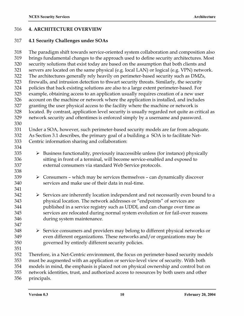
The paradigm shift towards service-oriented system collaboration and composition also 318 brings fundamental changes to the approach used to define security architectures. Most 319 security solutions that exist today are based on the assumption that both clients and 320 servers are located on the same physical (e.g. local LAN) or logical (e.g. VPN) network. 321 The architectures generally rely heavily on perimeter-based security such as DMZs, 322 firewalls, and intrusion detection to thwart security threats. Similarly, the security 323 policies that back existing solutions are also to a large extent perimeter-based. For 324 example, obtaining access to an application usually requires creation of a new user 325 account on the machine or network where the application is installed, and includes 326 granting the user physical access to the facility where the machine or network is 327 located. By contrast, application level security is usually regarded not quite as critical as 328 network security and oftentimes is enforced simply by a username and password. 329 330 Under a SOA, however, such perimeter-based security models are far from adequate. 331 As Section 3.1 describes, the primary goal of a building a SOA is to facilitate Net-332 Centric information sharing and collaboration: 333 334
Business functionality, previously inaccessible unless (for instance) physically 335 sitting in front of a terminal, will become service-enabled and exposed to 336 external consumers via standard Web Service protocols. 337 338 Consumers – which may be services themselves – can dynamically discover 339
services and make use of their data in real-time. 340 341 Services are inherently location independent and not necessarily even bound to a 342
physical location. The network addresses or “endpoints” of services are 343 published in a service registry such as UDDI, and can change over time as 344 services are relocated during normal system evolution or for fail-over reasons 345 during system maintenance. 346 347 Service consumers and providers may belong to different physical networks or 348
even different organizations. These networks and/or organizations may be 349 governed by entirely different security policies. 350
351 Therefore, in a Net-Centric environment, the focus on perimeter-based security models 352 must be augmented with an application or service-level view of security. With both 353 models in mind, the emphasis is placed not on physical ownership and control but on 354 network identities, trust, and authorized access to resources by both users and other 355 principals. 356

NCES Security Services Architecture
Version 0.3 11 February 20, 2004
Security within a Net-Centric environment has its own challenges: 357 358
1. Firewall Limitations – Allowing inbound HTTP access to Web Services opens up 359 servers to potential attack which may not be detectable by conventional firewall 360 products. For example, an ill-intended SOAP message may be constructed to 361 cause internal application buffer overflow while looking completely benign to 362 the firewall and the HTTP server. Recently many new XML firewall products 363 have emerged that attempt to protect Web Services at the SOAP level, but their 364 effectiveness has not been closely studied and the positioning of those products 365 within the entire enterprise security architecture is not yet clear. 366
367 2. Service-Level Security Semantics – As Section 3.3 describes, most of the 368
standardization efforts have focused on defining the wire formats needed for 369 security information exchange. The standards largely ignore the similar 370 challenge of defining the mechanism by which different parties interface with 371 each other to achieve security goals such as authentication and authorization. 372 For example, SAML defines the XML structures and protocols for sending 373 authentication assertions, but it doesn’t prescribe who should pass what 374 information to whom, when information should be passed, or how such 375 information may be used. 376
377 3. Interoperability of Security Solutions – Because of the lack of standard profiling 378
at the service interface level, Web Service security products in the market today 379 are not fully interoperable even though they all claim to be compliant with Web 380 Services security standards. Further, many are point solutions that do not meet 381 all requirements of a DoD enterprise security architecture, and are not capable of 382 extending beyond enterprise boundaries. 383
384 4. Secure Composition and Orchestration – As enterprise Web Services proliferate, 385
there is an increasing need for multiple services to interact among one another 386 within a joint business process or workflow. This situation presents many 387 security challenges. For example, SOAP is not a full-blown messaging protocol 388 and doesn’t have inherent provisions for a service consumer to specify the 389 destination(s) or the “itinerary” of an invocation sequence. As a result, the SOAP 390 message might be replayed to unintended 3rd parties bearing the same operation 391 signature. For more details on this issue, please see the Future Work section 392 towards the end of this document. 393
394 5. Multiple Security Domains and Classification Levels – Current guard 395
technologies are not yet connection-oriented and must evolve to support XML 396 and SOAP message security. 397
398
NCES Security Services Architecture
Version 0.3 12 February 20, 2004
6. Security vs. Performance – A PK-enabled security architecture involves many 399 computation-intensive tasks such as message signing, encryption, and certificate 400 validation. Sending a properly signed message may be many times slower than 401 a less secure version, and there is usually a direct inverse relationship between 402 performance and security. Cautious planning and effective optimization 403 techniques are necessary to ensure that a secured SOA environment will meet 404 operational requirements. 405
406 7. Impacts on Existing Policies and Processes – Current C&A policies generally 407
require identification of system boundaries, whereas in an SOA based network 408 trust relationships are established more dynamically. One possible solution is to 409 define the C&A boundaries at the Web Service interfaces. 410
411 Defining a service-level security architecture to address these challenges is the focus of 412 this paper. 413 414 4.2 Summary of Architectural Requirements 415
The primary goal of the security architecture defined in this document is to ensure 416 Enterprise Services (ES) can be invoked securely. As with every mission critical 417 distributed system there is a set of key security requirements that must be met: 418 419
1. Authentication – Most (if not all) service providers will require that consumers 420 are authenticated before accepting a service request. Service consumers will also 421 need to authenticate service providers when a response is received. Different 422 authentication mechanisms should be supported, and these mechanisms should 423 be configurable and interchangeable according to service-specific requirements. 424 425
2. Authorization – In addition to authentication of a service consumer, access to a 426 service will also require the consumer to possess certain privileges. These 427 privileges feed an authorization check that is usually based on access control 428 policies – who can access a service and under what conditions, for example. 429 Different models may be used for authorization, such as mandatory or role-430 based access control. The authorization implementation should also be 431 extensible to allow for domain- or COI-specific customizations. 432 433
3. Confidentiality – Protect the underlying communication transport as well as 434 messages or documents that are carried over the transport so that they cannot be 435 made available to unauthorized parties. Sometimes only a fragment of the 436 message or document (e.g. wrapped within a certain XML tag) may need to be 437 kept confidential. 438 439
NCES Security Services Architecture
Version 0.3 13 February 20, 2004
4. Data Integrity – Provide protection against unauthorized alteration of messages 440 during transit. 441 442
5. Non-repudiation – Provide protection against false denial of involvement in a 443 communication. Non-repudiation ensures that a sender cannot deny a message 444 already sent, and a receiver cannot deny a message already received. This is 445 especially important in monetary transactions and security auditing. 446 447
6. Manageability – The security architecture should also provide management 448 capabilities for the above security functions. These may include, but are not 449 limited to, credential management, user management, and access control policy 450 management. 451 452
7. Accountability – This includes secure logging and auditing which is also 453 required to support non-repudiation claims. 454
455 In addition, the following additional requirements are specific to or are also important 456 in a SOA environment: 457 458
1. Security Across Trust Domains – The architecture must provide a trust model 459 under which Web Service invocations across different trust domains can be 460 secured, just like those within a single trust domain. All basic security 461 requirements mentioned in Section 4.1 apply to cross-trust domain service 462 invocations. Additionally, such invocations must be controlled by the local 463 security policies of participating domains. 464 465
2. Interoperability – Interoperability is the cornerstone of SOAs, and the security 466 architecture must preserve this to the maximum extent possible. Major security 467 integration points in the architecture – such as those between service consumers 468 and service providers, between service providers and the security infrastructure, 469 and between security infrastructures in different trust domains – must have 470 stable, consistent interfaces based on widely adopted industry and government 471 standards. These interfaces enable each domain or organization to implement its 472 own market-driven solution while maintaining effective interoperability. 473 474
3. Modeling tailored constraints in security policies. In a traditional security 475 domain, resources and services are often protected by a uniform set of security 476 rules that are not granular enough to meet specific application needs. Under a 477 SOA, service provider requirements may vary in terms of how they need to be 478 protected. For example, one service may require X.509 certificate based 479 authentication whereas another service may only need username / password 480 authentication. Furthermore, because clients that access a resource may or may 481 not be from the local domain, different “strengths” of authentication and access 482

NCES Security Services Architecture
Version 0.3 14 February 20, 2004
control may be required. Consequently, security policies must be expressive and 483 flexible enough to be tailored according to Quality of Protection (QoP) 484 parameters and user attributes. 485 486
4. Allowing Integration with existing Information Assurance solutions, products, 487 and policies. The SOA-based security architecture does not intend to replace an 488 existing investment in security infrastructure. On the contrary, a flexible IA 489 solution should be designed to leverage existing IT investments without causing 490 any redundant development efforts. Seamless integration with existing security 491 tools and applications also increases the overall stability of the enterprise. 492 493
5. Securing other infrastructure services within the SOA, such as discovery, 494 messaging, mediation, and service management. 495 496
6. Unobtrusiveness. The architecture should be unobtrusive to other service 497 implementations. More specifically, to deploy unto the new security architecture, 498 a service provider shall not have to: 499
− Be constrained to use any one particular programming language; 500 − Port an existing service implementation to a specific hardware platform; 501 − Modify an existing implementation against any vendor-specific API 502
interfaces; 503 − Recompile or rebuild existing code sets 504
505 4.3 Scope, Assumptions, and Limitations 506
The following assumptions and limitations have been identified for the NCES Security 507 Services 0.3 Release: 508 509
1. The security architecture does NOT yet cover the implementation of Identity 510 Management. Rather, it aims to be flexible in this area so that it may leverage 511 and integrate with existing and / or emerging DoD identity management 512 systems. 513 514
2. The security architecture will support integration of digital certificates issued 515 from the DoD PKI. For this release, the architecture will be based on explicit 516 trust of the Certification Validation Service, which serves as a domain’s trust 517 anchor for establishing the authenticity and validity of certificates. Please refer 518 to Section 10.2 for detailed discussions on this approach and its alternatives. 519 520
3. The architecture currently does NOT yet address “edge” security such as end-521 user authentication or end-user Single Sign On (SSO). The ultimate SSO 522 experience, from the end user’s perspective, involves authenticating not just to 523 Web Services, but also to the network, the operating system, and/or any Identity 524

NCES Security Services Architecture
Version 0.3 15 February 20, 2004
Management system in use in the organization. This is beyond the scope of this 525 document and will be addressed in the near future. 526 527
4. The architecture currently does NOT support establishment and protection of 528 security contexts that span across multiple Web Services. 529 530
5. The architecture currently does NOT address message level security across 531 multiple security levels (MSL) or in a multi-level security (MLS) environment. 532 533
6. This architecture does NOT yet define enterprise audit and logging functionality 534 and related service specifications. They will be provided in the near future. 535 536
7. The architecture currently does NOT directly address content or data level 537 access control, such as enforcing proper access control over data contents and 538 information products contained as a SOAP message “payload”. For now this is 539 considered the responsibility of the service provider. However, the NCES 540 Security Services do provide support for managing and accessing security 541 policies that may be leveraged for this task. 542 543
8. The architecture assumes sufficient protection of physical security infrastructure 544 components. Security services such as the policy and credential management 545 services (as will be introduced in Section 4.5), as well as security repositories 546 such as the policy store should be protected using well-established policies and 547 practices for securing access to physical systems. 548 549
9. Web Services and the security infrastructure components (e.g., Policy Decision 550 Points) should also be sufficiently protected from format and data attacks. Some 551 of these attacks may be addressed by existing COTS products such as XML 552 firewalls, while others involve conformance to good security programming 553 practices such as preventing buffer overflows. The architecture document does 554 not yet address the means of performing these functions. 555
556 4.4 Conceptual Enterprise Security Architecture 557
Figure 3 presents a very high level illustration of the security architecture. The diagram 558 reflects the following concepts: 559 560
1. Service consumers and providers (shown on the left side of the diagram) 561 exchange security related information (e.g. certificates) with each other through 562 open security standards such as WS-Security and SAML. 563
2. The underlying security infrastructure is exposed as Web Services (shown in the 564 middle section of the diagram). This document defines a set of Security CES 565

NCES Security Services Architecture
Version 0.3 16 February 20, 2004
using technology-agnostic WSDL interfaces. Security functionality such as 566 credential and policy management are themselves wrapped as Web Services. 567
3. Instead of attempting to implement all security infrastructure components from 568 scratch, the security services leverage existing enterprise security infrastructure 569 (shown on the right side of the diagram) such as identity management, and PKI 570 through an integration backplane. 571
572
.
.
.
Data ServiceProviders
PolicyServices
App ServiceProviders
ThickClients
.
.
.
ThinClients
Stan
dard
-bas
ed S
ecur
ity In
fo E
xcha
nge
Plat
form
(WS-
Secu
rity
/ SA
ML
/ XK
MS)
KeyMgmt
Services
AttributeMgmt
Services
Monitoring &Management
Inte
grat
ion
Bac
k-pl
ane
User / ResourceDirectories
GuardsOther
SecurityDomains
Security Policies
PKIInfrastructure
Authentication Mechanisms
Web PortalsCACBiometrics, …
User / ResourceDirectories
GuardsOther
SecurityDomains
Security Policies
PKIInfrastructure
Authentication Mechanisms
Web PortalsCACBiometrics, …
DomainFederationServices
AuditingServices
SecurityContextServices
Security CES
573 Figure 3 - Conceptual Enterprise Security Architecture 574
575 The security architecture provides many important benefits: 576 577
Efficiency. A set of security services along with their backend infrastructures are 578 responsible for supporting application level security, so that service providers 579 themselves do not have to roll their own enterprise security management. This is 580 not only efficient but also significantly reduces operational overhead. (unless the 581 provider has application-specific security requirements which can be built on top 582 of the Security CESs). 583
Plug-and-play. The security service abstraction layer is able to provide true loose 584 coupling among applications and enhance overall system stability. As can be 585 seen from the diagram, this is reflected in the plug and play capability for both 586 security users and security infrastructure providers: On the left hand side of 587 Figure 3, service providers and consumers can easily plug in to the security 588

NCES Security Services Architecture
Version 0.3 17 February 20, 2004
framework because all interfaces are fully standards based. The right hand side 589 of the diagram details how security developers can swap security 590 implementations without affecting the Web Services and end users. These 591 changes are possible because the security service interfaces in the middle remain 592 the same. 593
Cross-domain interoperability. The security architecture is standards-based, 594 which enables secure collaboration and information sharing across trust 595 domains. As long as all trust domains conform to the same set of security service 596 specifications they are able to exchange security claims, entity attributes, and 597 access control policies. This level of cross-domain interoperability is critical for a 598 Net-Centric environment. 599
Future-proof. The architecture is well positioned for future evolution. The 600 security service specifications are platform-independent, technology-agnostic, 601 and vendor-neutral. This not only promotes reuse of existing infrastructures but 602 also allows for market-driven solutions and selection of best-of-breed products 603 without committing to vendor lock-in. 604
605 4.5 The Security CESs 606
The Security CESs, depicted in the middle box of Figure 3, consist of a number of 607 functional service groups, each of which may include one or more service interfaces 608 that perform specific tasks. In the current release, only the very basic interfaces that 609 support core Web Service security capabilities are defined; more services will be added 610 and existing services will be expanded in future versions to provide richer and more 611 sophisticated features. The taxonomy or functional breakdown of the Security CES is 612 shown in the table below: 613 614 Service Group Current Services Future Services* Policy Services Policy Decision Service
Policy Retrieval Service Policy Administration Service
Policy Subscription Service
Credential Management Services
Certificate Validation Service
Certificate Registration Service Certificate Retrieval Service
Attribute Services Principal Attribute Service Resource Attribute Service
Environment Attribute Service
Trust Domain Federation Services
None Domain Inquiry Service Domain Registration Service
Security Context Services None Security Context Service

NCES Security Services Architecture
Version 0.3 18 February 20, 2004
Service Group Current Services Future Services* Auditing and Logging Services
None Secure Logging Service Auditing Service
Table 2 - Security CES Taxonomy 615
* Note the future service offerings and their names are subject to change 616 617 In the following sub-sections, the service groups and their current member services are 618 briefly described. Detailed technical specifications of the above services will be defined 619 in a separate document. 620 621 4.5.1 Policy Services 622
623 This service group provides policy-based authorization and access control for Web 624 Services and system resources. The current services include: 625 626 Policy Decision Service – serves as a SAML authorization authority for service 627
providers that choose to use an external Policy Decision Point (PDP). This 628 service accepts authorization queries and returns authorization decision 629 assertions, all of which conform to the SAML Protocol. The heart of the service is 630 a policy evaluation engine, which applies policies based on a variety of inputs 631 such as the target resource, the action or operation requested, identity of the 632 requester, etc. 633
Policy Retrieval Service – exposes security policies in XACML format. This 634 service can allow service providers to retrieve policies for their resources, 635 especially when they choose to implement their own PDP logic (see Section 8.2 636 for details). This service can also be used by applications other than Web 637 Services to retrieve stored resource policies (e.g. access control over portlets in a 638 portal server). 639
Policy Administration Service – This service uses XACML as a standard policy 640 exchange format and can be used by management applications to compose, 641 modify, and control authorization policies. Depending on the access control 642 model adopted in the domain, this service’s functionality may include Create, 643 Read, Update, Delete (CRUD) operations for policy rules, rule sets, roles, 644 permissions, security categories and compartment labels, among others. Section 645 9 describes the recommended RBAC model upon which the current reference 646 implementation is based. 647
648 In the near future, a Policy Subscription Service will also be defined, along with 649 related callback interfaces that allow interested parties to subscribe to and thereby 650 receive real-time notifications on policy changes. 651

NCES Security Services Architecture
Version 0.3 19 February 20, 2004
652 4.5.2 Credential Management Services 653
654 This group of services provides access to the underlying DoD PKI infrastructure. 655 The group is envisioned to offer a subset of XKMS functionality, starting with the X-656 KISS spec and potentially moving into X-KRSS as well. Currently only the following 657 service is defined: 658 659 Certificate Validation Service (CVS) – This service allows clients to delegate part 660
or all certificate validation tasks, which is especially useful when the client side 661 doesn’t have the capability for PKI processing. The service corresponds to a “Tier 662 2 Validation Service” as defined in the XKMS spec , and shields client 663 applications from such PKI complexities as X.509v3 certificate syntax processing 664 (e.g. expiration), revocation status checking, and certificate path validation. 665 Moreover, offloading validation operations allows it to be done in a more 666 efficient and optimized fashion. The architecture allows a service provider to use 667 the Certificate Validation Service (CVS) to only perform revocation status 668 checking, in which case the CVS functions similar to a PKIX Online Certificate 669 Status Protocol (OCSP) responder; OR to offload the entire certification 670 validation to CVS. This service, as well as the underlying DoD PKI functionality, 671 is discussed in much greater detail in Section 10.2. 672
673 In the future the following additional services could potentially be provided: 674 675
Certificate Registration Service. Web Service providers and consumers require 676 public key certificates to perform digital signature and encryption operations 677 with other clients. If a client generates its own public/private key pair, it needs 678 to request a certificate for the public key from the DoD PKI. The Certificate 679 Registration Service would use the XKMS XML Key Registration Service 680 Specification (X-KRSS) “register” service as the interface presented to Web Service 681 clients for public key certificate request and response. The X-KRSS “register 682 request” message contains the identity and associated public key of the certificate 683 being requested, and a proof of possession element (i.e., proof that the certificate 684 requester is the actual holder of the private key corresponding to the public key 685 in the request). The Certificate Registration Service translates the information 686 contained in the X-KRSS register request to the certificate request format(s) used 687 by the DoD PKI. The X-KRSS “register response” message contains the resultant 688 X.509 public key certificate. 689
Certificate Retrieval Service. Web Service providers and consumers must have 690 the capability to obtain the public key certificates of users and other Web 691 Services clients for the purposes of authentication verification, digital signature 692 verification, and public key encryption operations. In some cases, the 693 originator’s public key certificates are included in XML messages inbound to the 694

NCES Security Services Architecture
Version 0.3 20 February 20, 2004
Web Services client. In other cases the certificates are not included in the inbound 695 messages and the Web Service clients must retrieve them from the DoD PKI 696 directory system. The Certificate Retrieval Service would use the XKMS XML 697 Key Information Service Specification (X-KISS) “locate” service as the interface 698 presented to Web Services clients for public key certificate retrieval. The X-KISS 699 “locate request” message contains the identity of the public key certificate being 700 sought. The Certificate Retrieval Service interfaces with a DoD PKI directory 701 system (e.g., the DoD Global Directory Service (GDS)), to locate and retrieve the 702 requested certificate. The X-KISS “locate response” message contains the 703 requested X.509 certificate, if it is found in the DoD PKI directory system. Note 704 that the Certificate Retrieval Service would not check the revocation status or 705 validity of the certificate retrieved; it would simply return a certificate if one is 706 successfully located in the directory. 707
708 4.5.3 Attribute Services 709
710 In order to support policy-based decisions, various attributes are needed. This 711 includes those of the principals, the system resources, and the application 712 environment. This service group provides standard access mechanisms for such 713 attributes, and defines how attribute queries are returned as SAML attribute 714 assertions. The request-response mechanism is also based on the standard SAML 715 Protocol. A Principal Attribute Service is currently defined: 716
717 Principal Attribute Service – provides query and retrieval interfaces to access 718
attributes for principals, which may be individuals or even organizations. The 719 attribute taxonomy or “schema” is not defined by the service, but rather by the 720 underlying attribute authorities (e.g. identity stores). These attributes are 721 retrieved upon request and provided as SAML assertions that may be used as 722 inputs to the policy decision logic. Currently, principal attributes are primarily 723 managed by existing Identity Management systems and then stored in various 724 directories. Therefore this service provides just the “read” functionality to obtain 725 those stored attributes in an assertion that binds them with the principal’s 726 identity. 727 728 In future versions of this service, additional sources of principal attributes will be 729 considered, and mechanisms will be provided to restrict access to sensitive 730 attributes. 731
732 In the near future, a Resource Attribute Service and potentially an Environment 733 Attribute Service will also be defined for retrieving resource and environment 734 attributes, respectively. When it becomes necessary to actively manage those 735 attributes, a set of Attribute Administration Services providing the complete CRUD 736 operations will be defined as well. 737

NCES Security Services Architecture
Version 0.3 21 February 20, 2004
738 4.5.4 Trust Domain Federation Services 739
740 The Trust Domain Federation Services is responsible for managing a trust domain’s 741 trust relationships with other domains. Its interfaces may include registering and 742 deregistering other domains as trusted parties, and inquiring about established trust 743 relationships. 744 745 These services will be defined in future versions of the architecture. 746
747 4.5.5 Security Context Services 748
749 These services provide mechanisms for sharing security contexts across multiple Web 750 Services. Such contexts are necessary in a dynamic SOA environment where 751 indirect or brokered trust relationships abound. For example, when service A 752 invokes service B on an end-user’s behalf (see Section 6 for detail on the service 753 chaining scenario), a common security context can help establish a boundary for this 754 unit of work so that, for instance, service A cannot forward the request to an 755 unintended service C even if A possesses a valid user assertion. 756 757 In an enterprise service environment, security contexts are important in addressing 758 service orchestrations and workflows. They may also help improve efficiency 759 especially in interactive scenarios. For example, results of certain authentication and 760 authorization steps may be performed only once for a series of consumer-provider 761 interactions within a common security context. 762 763 The Security Context Services will be defined in the future. Currently there are 764 standard proposals such as WS-Trust, WS-SecureConversation, and WS-765 Coordination that address this topic. Future service specifications will consider 766 conformance to them once they become approved. 767
768 4.5.6 Auditing and Logging Services 769
770 Enterprise auditing is also an important requirement for the security architecture. 771 Two pieces of functionality need to be provided: recording the service level 772 activities (logging), and identifying anomalies (such as access violations or attacks) 773 from those records. Currently the service level logging are performed locally by 774 SDKs (see Section 6.1 for details) deployed at service consumers and providers. The 775 logs include: 776 777 Outbound message information (message ID, sending timestamp, host, target 778
service, etc.) 779 Inbound message information (message ID, receiving timestamp, etc.) 780 Message signature verification (success / faults) 781

NCES Security Services Architecture
Version 0.3 22 February 20, 2004
Certificate validation and status checking results (success / faults) 782 Policy decision results (permit / deny / indeterminate) 783 Invocation status (resource, action, success / faults) 784
785 In the near future, service interfaces will be defined for remote logging and auditing. 786
787 To reiterate, the service interfaces defined by this architecture are specifications, not 788 implementations. The actual implementations may utilize best-of-breed COTS and 789 GOTS technologies and may vary in different IT environments, but the specifications 790 will remain stable and interoperable. Going forward it is envisioned that the 791 specifications will be driven by the collective efforts of various NCES initiatives and 792 their requirements, while at the same time reflecting current industry best practices. 793 794
795

NCES Security Services Architecture
Version 0.3 23 February 20, 2004
5. THE TRUST MODEL 795
5.1 The Micro View 796
The security architecture defined in this document consists of two logical components: 797 798
1) A trust model under which Web Service consumers and providers interact with 799 one another; 800
2) A set of security Core Enterprise Services that provide the functionality 801 necessary to support the model and are based on open XML security standards. 802 These services were defined in the previous section. 803
804 This section introduces the basic trust model that serves as the foundation of the NCES 805 security architecture. It is presented in a “bottom-up” approach: We start with the 806 “micro” view by looking at the trust model and associated Security Services in a single 807 Trust Domain; then we zoom out to the “macro” view, describing how the model and 808 supporting services would look when multiple Trust Domains are involved. 809 810 Under the basic model, a Trust Domain consists of a “triad” of one or more Web 811 Service Providers, Service Consumers, and a set of Security CESs, as shown in Figure 812 4 below. As defined previously, a Web Service Provider may provide a collection of 813 multiple Web Services, hosted together for a common business purpose. The provider 814 may be physically located on one or more server machines. The diagram shows two 815 kinds of Web Service consumers: 816 817
“Edge” applications, which provide the presentation layer and user interaction 818 logic (often web-based, but does not have to be), and serve as entry points of end 819 users for accessing the service layer. The edge applications initiate service 820 requests on behalf of end users. As mentioned in the assumptions, this service 821 level security architecture does not focus on the security between individual 822 users and edge applications. The mechanism, context and strength of edge 823 security, however, must be captured and propagated for downstream policy 824 decisions, as discussed in later sections. 825 In addition, a service provider may in turn be a consumer of other Web Services. 826
This is often seen in service composition and workflow scenarios. 827 828

NCES Security Services Architecture
Version 0.3 24 February 20, 2004
Trust DomainTrust Domain
WebServiceProvider
WebServiceProvider
WebServiceProvider
Oth
er T
rust
Dom
ains
Edge Applications
Security CES
PolicyMgmt
Service
PolicyDecisionService
…End Users
Trust DomainTrust Domain
WebServiceProvider
WebServiceProvider
WebServiceProvider
Oth
er T
rust
Dom
ains
Edge Applications
Security CES
PolicyMgmt
Service
PolicyDecisionService
…PolicyMgmt
Service
PolicyMgmt
Service
PolicyDecisionService
PolicyDecisionService
……End Users
829 Figure 4 – The Micro View: Within a Single Trust Domain 830
831 This diagram reflects the concept of Indirect, or Brokered Trust: one party trusts a second 832 party who, in turn, trusts or vouches for, a third party [WST]. Furthermore, instead of 833 having Web Service providers themselves authorize users and control their access (i.e. 834 the Direct Trust model), such responsibilities are assisted and sometimes taken over by 835 the Security infrastructure and related CESs. 836 837 The brokered trust model has some obvious benefits when compared with the direct 838 trust model: 839 840
It’s non-invasive because service providers do not have to bear the burden of 841 implementing security enforcement logic and managing security policies; 842 Service providers can, on the end user’s behalf, serve as active intermediaries or 843
“brokers” of information offered by other services, thereby enabling “power to 844 the edge”. 845 Because brokered trust relationships are more flexible and more dynamic, the 846
architecture is more resilient and able to quickly adapt to new missions and new 847 business requirements, making it well suited for the dynamic Net-Centric 848 environment. 849
850 Section 6 describes this security model within a single trust domain in much greater 851 technical detail. 852 853

NCES Security Services Architecture
Version 0.3 25 February 20, 2004
5.2 The Macro View 854
Earlier in the document a Trust Domain was defined as a purely logical realm that 855 contains a set of system entities that are governed by a set of common security policies. 856 The delineation of a (logical) trust domain boundary really depends on the extent of the 857 policies; it may or may not coincide with organizational network boundaries (e.g. 858 security enclaves). Just as policies may be defined at different organizational levels, 859 trust domains may also be created at different levels or scales. In addition to the DoD 860 Enterprise Domain that is the primary focus of this architecture, there may also be 861 smaller domains that could benefit from an approach such as this. Examples of such 862 domains include: 863 864
A local trust domain containing resources and services controlled under the 865 discretion of an individual user, located on the user’s PC; 866 An enclave-wide trust domain containing resources and services in a security 867
enclave; 868 An agency-wide trust domain that coincides with the administrative domain of a 869
DoD agency or other type of office. For example, the Defense Information 870 Systems Agency (DISA) may have its own trust domain; 871 A DoD Enterprise domain for all DoD Enterprise Services; 872 A Community of Interest (COI) domain that encompasses multiple organizations 873
collaborating with one another sharing a common interest. Examples may 874 include an Intelligence Community (IC) domain, a Command and Control (C2) 875 domain, and so on. A COI trust domain might in fact overlap with other trust 876 domains. 877
878 From the “macro” view, the architecture can be summarized (rather informally) as 879 follows: 880 881
1) The security architecture consists of multiple associated trust domains at 882 multiple levels. A trust domain may have peers and /or may join a “parent” 883 domain; 884
2) Within a trust domain, the local security policies control access to local resources 885 by both local principals and principals from other trust domains; 886
3) Trust domains may overlap one another. In this case, a resource may be 887 governed by different policies from more than one domain depending on the 888 service invocation context. 889
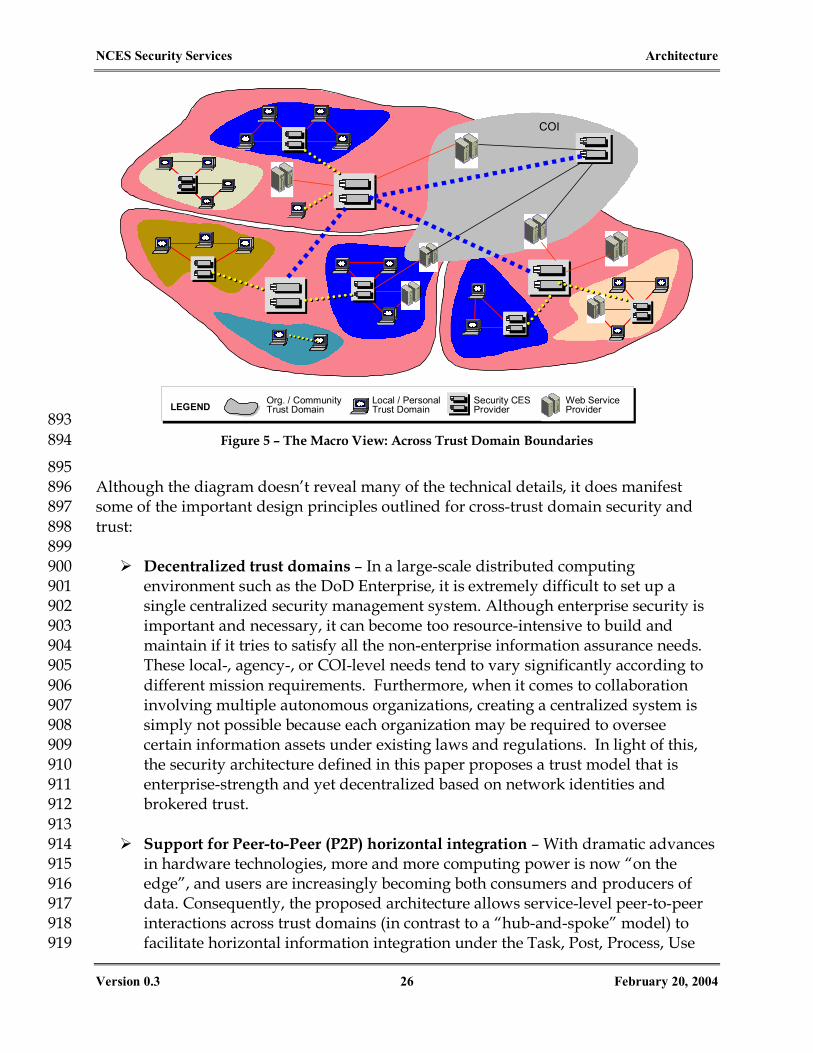
890 The model is conceptually depicted in the diagram in Figure 5. 891 892
NCES Security Services Architecture
Version 0.3 26 February 20, 2004
Org. / CommunityTrust Domain
Local / PersonalTrust Domain
Security CESProvider
Web ServiceProviderLEGEND
COI
893 Figure 5 – The Macro View: Across Trust Domain Boundaries 894
895 Although the diagram doesn’t reveal many of the technical details, it does manifest 896 some of the important design principles outlined for cross-trust domain security and 897 trust: 898 899
Decentralized trust domains – In a large-scale distributed computing 900 environment such as the DoD Enterprise, it is extremely difficult to set up a 901 single centralized security management system. Although enterprise security is 902 important and necessary, it can become too resource-intensive to build and 903 maintain if it tries to satisfy all the non-enterprise information assurance needs. 904 These local-, agency-, or COI-level needs tend to vary significantly according to 905 different mission requirements. Furthermore, when it comes to collaboration 906 involving multiple autonomous organizations, creating a centralized system is 907 simply not possible because each organization may be required to oversee 908 certain information assets under existing laws and regulations. In light of this, 909 the security architecture defined in this paper proposes a trust model that is 910 enterprise-strength and yet decentralized based on network identities and 911 brokered trust. 912
913 Support for Peer-to-Peer (P2P) horizontal integration – With dramatic advances 914
in hardware technologies, more and more computing power is now “on the 915 edge”, and users are increasingly becoming both consumers and producers of 916 data. Consequently, the proposed architecture allows service-level peer-to-peer 917 interactions across trust domains (in contrast to a “hub-and-spoke” model) to 918 facilitate horizontal information integration under the Task, Post, Process, Use 919

NCES Security Services Architecture
Version 0.3 27 February 20, 2004
(TPPU) paradigm. For example, several Web Services from different 920 organizations may join a COI and work together in enhancing target tracking 921 data for better situational awareness. Note that such interactions will of course 922 be subject to enterprise security policies as well as domain-specific constraints. 923
924 Delegation of authority for increased manageability – In addition to horizontal 925
integration, the architecture also supports seamless vertical integration. As 926 already mentioned, in the DoD Enterprise with potentially millions of users and 927 millions more resources, having a central authorization authority is too inflexible 928 and simply won’t scale. With a model of multi-level trust domains, policy 929 management on the resources is delegated down to the appropriate level where 930 the resource is located and owned, from communities to organizations or even to 931 individuals, effectively optimizing the management span at each level. The 932 enterprise domain can then focus on managing critical, enterprise-wide resources 933 and services, while leaving other entities to be managed by lower-level domains. 934 The delegation happens in the other direction as well: policy decisions that are 935 beyond the discretion of the local trust domain (e.g. granting access to a principal 936 from an unrecognized trust domain), can be passed on to other authorities (e.g. 937 the parent trust domain or a COI authority). 938
939 Self-similarity – As shown in Figure 5, at different scales, the trust domains 940
interact with one anther in basically the same fashion. In fact, the same set of 941 NCES Security Services are used at every domain level. In other words, the 942 architecture exhibits “self-similar” (a.k.a. “fractal”) behavior, which bears this 943 important characteristic: To design efficient models for services at various scales of the 944 network, it is often sufficient to understand the behavior and characteristics at a fairly 945 simple scale level. The benefit of this behavior is therefore two-pronged: it gives 946 the architecture infinite scalability yet also contains its complexity. It has been 947 argued that the success of the World Wide Web is in part due to the pervasive 948 self-similarity exhibited in its usage behavior [SIMWEB]. 949
950 In this release a focus is placed on the intra-trust domain aspects of the security 951 architecture. Technical details of the cross-trust domain aspects will be covered in 952 future versions of this document. 953
954

NCES Security Services Architecture
Version 0.3 28 February 20, 2004
6. SECURITY ARCHITECTURE WITHIN A TRUST DOMAIN 954
The trust model introduced in the previous section was purposely technology-agnostic: 955 There was no mention of any specific wire protocols, interfaces, or data models, except 956 that everything will be Web Services based. Starting in this section we begin filling in 957 the semantic and syntactical details, taking advantage of industry standards from the 958 technology stack in Figure 2 as much as possible. Over time, these standards will evolve 959 and new standards will continue to emerge, but the conceptual architecture is 960 inherently stable and will remain the same. 961 962 6.1 Securing the Invocation Path 963
964
Edge ApplicationEdge Application
WSS
Security CESSecurity CES
CertificateValidation
Service
PolicyRetrieval
Service
SOAPClient
SOAPClient
Msg
Han
dler
s
NCES SDK
1
2-a2-b
3
7
Web Service ProviderWeb Service Provider
WebService
WebService
WebService
WebService
Mes
sage
Han
dler
s (in
)
Mes
sage
Han
dler
s (o
ut)
5
NCES SDK
PolicyAdmin.Service
XKMS
Management Console
PolicyDecisionService
Edge
Use
rAu
then
ticat
ion
IdentityStore
IdentityStore
Key StoreKey StoreKey StoreKey Store
2-c
2-d
Key StoreKey Store
SAML-P
PolicyStore
PolicyStore
XACML3-alt.
CRLCRL
6
8
4
0
PrincipalAttributeService
PrincipalAttributeService
Invocation Path “Out-of-band” Calls Signed MessageLEGEND
Edge ApplicationEdge Application
WSS
Security CESSecurity CES
CertificateValidation
Service
CertificateValidation
Service
PolicyRetrieval
Service
PolicyRetrieval
Service
SOAPClient
SOAPClient
Msg
Han
dler
s
NCES SDK
1
2-a2-b
3
7
Web Service ProviderWeb Service Provider
WebService
WebService
WebService
WebService
WebService
WebService
WebService
WebService
Mes
sage
Han
dler
s (in
)
Mes
sage
Han
dler
s (o
ut)
5
NCES SDK
PolicyAdmin.Service
PolicyAdmin.Service
XKMS
Management Console
PolicyDecisionService
PolicyDecisionService
Edge
Use
rAu
then
ticat
ion
IdentityStore
IdentityStore
Key StoreKey StoreKey StoreKey Store
2-c
2-d
Key StoreKey Store
SAML-P
PolicyStore
PolicyStore
XACML3-alt.
CRLCRL
6
8
4
0
PrincipalAttributeService
PrincipalAttributeService
PrincipalAttributeService
PrincipalAttributeService
Invocation Path “Out-of-band” Calls Signed MessageLEGEND Invocation Path “Out-of-band” Calls Signed MessageLEGEND 965
Figure 6 - Logical Security Architecture, Single Trust Domain 966
967 Figure 6 illustrates the logical security architecture using a typical scenario involving an 968 edge application (e.g. a web portal) acting as a service consumer that invokes and 969 consumes a Web Service provider. 970 971

NCES Security Services Architecture
Version 0.3 29 February 20, 2004
In addition to the Security CESs, the diagram introduces some additional components 972 involved in the security architecture: 973 974
For service providers and consumers, an NCES Service Development Kit (SDK) 975 is typically deployed along with the application to facilitate interactions with 976 NCES Core Enterprise Services (which includes security). A reference 977 implementation of the SDK is being provided along with the Security CES, but 978 additional implementations that leverage the same architecture may be built in 979 the future. 980 It is important to note that SDKs are platform- and technology-specific tools that are only 981 provided as developer aids, so that access to the standard Security CES interfaces may be 982 rapidly enabled. They are not an architecture component per se, nor should they be 983 treated as standards. To achieve true Net-Centricity, applications should only rely 984 on the Web Service standards, Security CES WSDL interfaces, and the processing 985 rules as outlined in this document. In fact, it is perfectly possible for a service 986 provider to implement its own security logic that is compliant to the security 987 architecture without using a third-party SDK. 988
The security part of the SDK also includes a set of SOAP Message Handlers, 989 which can “intercept” inbound and outbound* SOAP messages at runtime and 990 apply security related processing in a way that is transparent to application logic. 991 Multiple message handlers can be “chained” together and can be configured at 992 deployment time, which enables flexible and extensible security configurations. 993 For example, an auditing handler may be added in front of the authentication 994 and policy enforcement handlers, as illustrated in Figure 7: 995
996
* Note that “inbound” and “outbound” are relative terms. The same SOAP request is an outbound message to the service
consumer but an inbound message to the service provider. Because a service provider can also be a consumer to other services, the SDK includes both inbound and outbound message handlers.
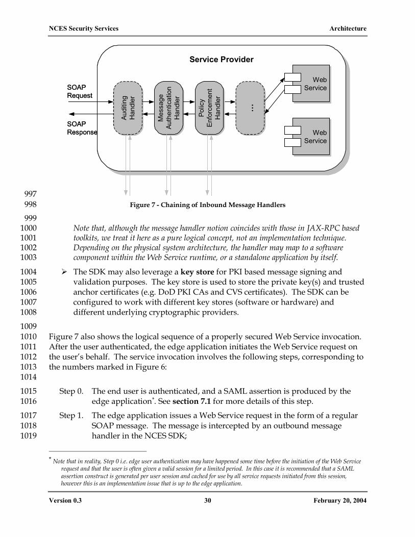
NCES Security Services Architecture
Version 0.3 30 February 20, 2004
Service ProviderService Provider
WebService
WebService
WebService
WebService
Mes
sage
Auth
entic
atio
nH
andl
er
Mes
sage
Auth
entic
atio
nH
andl
er
Audi
ting
Han
dler
Audi
ting
Han
dler
……
SOAPRequest
SOAPResponse
Polic
yEn
forc
emen
tH
andl
er
Polic
yEn
forc
emen
tH
andl
er
Service ProviderService Provider
WebService
WebService
WebService
WebService
WebService
WebService
WebService
WebService
Mes
sage
Auth
entic
atio
nH
andl
er
Mes
sage
Auth
entic
atio
nH
andl
er
Audi
ting
Han
dler
Audi
ting
Han
dler
……
SOAPRequest
SOAPResponse
Polic
yEn
forc
emen
tH
andl
er
Polic
yEn
forc
emen
tH
andl
er
997 Figure 7 - Chaining of Inbound Message Handlers 998
999 Note that, although the message handler notion coincides with those in JAX-RPC based 1000 toolkits, we treat it here as a pure logical concept, not an implementation technique. 1001 Depending on the physical system architecture, the handler may map to a software 1002 component within the Web Service runtime, or a standalone application by itself. 1003
The SDK may also leverage a key store for PKI based message signing and 1004 validation purposes. The key store is used to store the private key(s) and trusted 1005 anchor certificates (e.g. DoD PKI CAs and CVS certificates). The SDK can be 1006 configured to work with different key stores (software or hardware) and 1007 different underlying cryptographic providers. 1008
1009 Figure 7 also shows the logical sequence of a properly secured Web Service invocation. 1010 After the user authenticated, the edge application initiates the Web Service request on 1011 the user’s behalf. The service invocation involves the following steps, corresponding to 1012 the numbers marked in Figure 6: 1013 1014
Step 0. The end user is authenticated, and a SAML assertion is produced by the 1015 edge application*. See section 7.1 for more details of this step. 1016
Step 1. The edge application issues a Web Service request in the form of a regular 1017 SOAP message. The message is intercepted by an outbound message 1018 handler in the NCES SDK; 1019
* Note that in reality, Step 0 i.e. edge user authentication may have happened some time before the initiation of the Web Service
request and that the user is often given a valid session for a limited period. In this case it is recommended that a SAML assertion construct is generated per user session and cached for use by all service requests initiated from this session, however this is an implementation issue that is up to the edge application.

NCES Security Services Architecture
Version 0.3 31 February 20, 2004
Step 2. Signed SOAP request is sent from client to server, using WSS and XML-1020 DSIG protocols as prescribed in Section 7.2. This step can be further broken 1021 down into the following: 1022
1023
2-a. The outbound message handler on the client-side signs the SOAP 1024 request using the application’s private key. The digital signature not 1025 only serves as the “proof of possession” of the private key which 1026 ensures message authenticity, but also protects the message integrity 1027 so that any tampering in transit would be detected; 1028
2-b. The SOAP request is sent to the target service provider using standard 1029 Internet protocols (e.g. HTTP); 1030
2-c. An inbound message handler on the server side intercepts the SOAP 1031 request, then verifies the digital signature contained in the message. 1032 The handler also validates the sender’s PKI certificate to make sure it’s 1033 authentic*; 1034
2-d. The message handler further checks the status of the sender’s 1035 certificate against the Certificate Validation Service, making sure the 1036 certificate is not revoked. 1037
1038 In addition to the above steps, the handler in fact performs additional 1039 checks such as detecting replay. Section 7.2 describes message level 1040 authentication in greater detail. The above steps are common for all service 1041 requests and responses that need authentication, such as Steps 3, 4, and 7 in 1042 Figure 6. For simplicity sake, the sub-steps a ~ d are not repeated in the 1043 diagram for the latter messages. 1044
Step 3. After successfully authenticating the request, the inbound message handler 1045 proceeds to authorize the request. It MAY send a SAML authorization 1046 decision query to the Policy Decision Service (PDS), passing the resource 1047 identifier, the intended action, and supporting evidence such as the SAML 1048 assertion from the SOAP request. This message is also signed using the 1049 service provider’s private key for message authenticity and integrity 1050 protection. 1051
Step 4. The PDS evaluates the SAML query and makes a decision (permit / deny / 1052 indeterminate) based on the evidence and the access control policies of this 1053 trust domain. If necessary, the PDS may choose to obtain additional 1054 attributes for the user and the resource involved. The decision is sent back 1055 to the service provider in the form of a SAML authorization decision 1056 assertion within a signed SOAP response. 1057
*As mentioned before, in the future the handler may also choose to offload the validation step to the CVS in Step 2-d, but in this
release CVS only performs revocation status checking.

NCES Security Services Architecture
Version 0.3 32 February 20, 2004
1058 Alternatively, if the service provider chooses to make the policy decision by 1059 itself, steps 3 and 4 are no longer necessary. In support of this, the SDK may 1060 request relevant XACML policies from the Policy Retrieval Service (PRS), 1061 shown as step “3-alt.” in the diagram. Further, policy retrieval can happen 1062 in advance and therefore does not have to be in the invocation path. 1063 1064 It is worth noting, however, that the decision whether or not to use an 1065 external PDS may also depend on administration policies of the trust 1066 domain. 1067 1068 Section 8 formally describes the policy based authorization architecture. 1069
Step 5. If access is authorized, the message handler forwards the original SOAP 1070 request to the target Web Service for processing. 1071
Step 6. The service processes the request and sends back a synchronous SOAP 1072 response. 1073
Step 7. When the response goes back through the message handlers, it is signed 1074 with the provider’s private key using identical steps shown for Step 2. 1075
Step 8. On the consumer side, after verifying the provider’s signature, the message 1076 handler passes the SOAP response to the edge application. 1077
1078 6.2 Service Chaining* 1079
This basic invocation sequence may be easily extended to more complex usage 1080 scenarios. For instance, the Web Service may invoke another service on the user’s 1081 behalf. This so-called “service chaining” scenario is shown in Figure 8 below. 1082 1083
* Note that this document differentiates between “Service Chaining” and “Service Routing”. The latter refers to a Web Service
request being forwarded through intermediaries, intact, to the target service.

NCES Security Services Architecture
Version 0.3 33 February 20, 2004
Security CESSecurity CES
CertificateValidation
Service
PolicyRetrieval
Service
XKMS
Management Console
PolicyDecisionService
Key StoreKey Store
SAML-P XACML
Edge ApplicationEdge Application
WSS
SOAPClient
SOAPClient
Msg
Han
dler
s
NCES SDK
1
3
2
Service Provider AService Provider A
WebService
WebService
WebService
WebService
Mes
sage
Han
dler
s (in
)
Mes
sage
Han
dler
s (o
ut)
NCES SDKEdge
Use
rAu
then
ticat
ion
IdentityStore
IdentityStore
Key StoreKey Store Key StoreKey Store
CRLCRL
0
7
Service Provider BService Provider B
WebService
WebService
WebService
WebService
Mes
sage
Han
dler
s (in
)
Mes
sage
Han
dler
s (o
ut)
NCES SDK
Key StoreKey Store
4 5
8WSS
6
PolicyAdmin.Service
PolicyStore
PolicyStore
PrincipalAttributeService
PrincipalAttributeService
Invocation Path “Out-of-band” Calls Signed MessageLEGEND
Security CESSecurity CES
CertificateValidation
Service
CertificateValidation
Service
PolicyRetrieval
Service
PolicyRetrieval
Service
XKMS
Management Console
PolicyDecisionService
PolicyDecisionService
Key StoreKey Store
SAML-P XACML
Edge ApplicationEdge Application
WSS
SOAPClient
SOAPClient
Msg
Han
dler
s
NCES SDK
1
3
2
Service Provider AService Provider A
WebService
WebService
WebService
WebService
WebService
WebService
WebService
WebService
Mes
sage
Han
dler
s (in
)
Mes
sage
Han
dler
s (o
ut)
NCES SDKEdge
Use
rAu
then
ticat
ion
IdentityStore
IdentityStore
Key StoreKey Store Key StoreKey Store
CRLCRL
0
7
Service Provider BService Provider B
WebService
WebService
WebService
WebService
WebService
WebService
WebService
WebService
Mes
sage
Han
dler
s (in
)
Mes
sage
Han
dler
s (o
ut)
NCES SDK
Key StoreKey Store
4 5
8WSS
6
PolicyAdmin.Service
PolicyAdmin.Service
PolicyStore
PolicyStore
PrincipalAttributeService
PrincipalAttributeService
PrincipalAttributeService
PrincipalAttributeService
Invocation Path “Out-of-band” Calls Signed MessageLEGEND Invocation Path “Out-of-band” Calls Signed MessageLEGEND 1084 Figure 8 - Service Chaining 1085
1086 In this case, Service Provider A is also a consumer of Service Provider B, and acts as a 1087 SOAP client just like the edge application. The invocation steps in the diagram (Steps 0 1088 to 8, response path not numbered) are self-explanatory. 1089 1090 From the authentication perspective, when Service Provider A makes a request to 1091 Provider B, two scenarios are possible: 1092 1093
In many cases, Provider A invokes B on behalf of the original end user. This 1094 would require Provider A to pass on the original SAML assertion in the second 1095 SOAP request, as opposed to creating a new one. Here Provider A “vouches for” 1096 the assertion by signing the message with its digital signature, even though it is 1097 not the issuer of the assertion. In the same way that Provider A authorized the 1098 first request, Provider B then needs to authorize the second request based on 1099 both its policies applicable to the end user AND its trust relationship with A. 1100
Alternatively, Provider A may choose to invoke B on its own behalf. This is also 1101 not uncommon. For example, B may be a data service that provides “wholesale” 1102 data to a small handful of applications, and may be relying on them to deal with 1103 end user related access control policies. In this case, Provider A still needs to 1104 authenticate itself to B (e.g. via digital signatures), but no longer needs to pass on 1105 the originating user assertion. Provider B’s authorization decision will be based 1106 on A’s principal instead of the original user’s. 1107

NCES Security Services Architecture
Version 0.3 34 February 20, 2004
1108 Both scenarios are supported under this architecture. The next two sections will 1109 examine them in much greater detail. 1110 1111
1112

NCES Security Services Architecture
Version 0.3 35 February 20, 2004
7. AUTHENTICATION 1112
Because the subsequent sections involve more technical discussions in the SOAP 1113 messaging layer, it is necessary to adopt a set of consistent messaging terms so that their 1114 connotations can be clearly understood within the context of this document. In addition 1115 to Service Consumer and Service Provider, the following terms will be used: 1116 1117
Message sender and recipient. These terms are used in a point-to-point context 1118 and are only relevant to a particular SOAP message (either request or response). 1119 For example, a service consumer is a sender of a SOAP request message but a 1120 recipient of a response message. 1121 Message originator. As discussed in Section 6.2, a Web Service request may be 1122
issued on behalf another system entity, either an end user or an application. This 1123 entity, if exists, is called the originator of the Web Service request of interest. 1124
1125 These terms are illustrated in Figure 9 below: 1126 1127
ConsumerConsumer ProviderProvider
SOAP Request
SOAP Response
Sender Recipient
SenderRecipient
User /Application/ Service
User /Application/ Service
Originator
ConsumerConsumer ProviderProvider
SOAP Request
SOAP Response
Sender Recipient
SenderRecipient
User /Application/ Service
User /Application/ Service
Originator
1128 Figure 9 - Messaging Terms 1129
1130 1131 7.1 Asserting the Authentication of End Users 1132
In the scenario illustrated in Figure 6, the edge application is responsible for 1133 authenticating end users, which is shown as “Step 0” in the diagram. The exact 1134 mechanism and policies for this step depend on the actual portal server as well as the 1135 trust domain environment, therefore is not prescribed here. However, in order for 1136 downstream service providers to make authorization decisions, the user identity and 1137 the actual context under which the user is authenticated need to be propagated along 1138 with the Web Service request. 1139 1140 In order to access downstream Web Services on an end user’s behalf, the edge 1141 application MUST provide a SAML assertion that includes the following information: 1142 1143
NCES Security Services Architecture
Version 0.3 36 February 20, 2004
1. [REQUIRED] Issuer of the assertion is required by the SAML spec, which is the 1144 identity of the edge application itself; 1145
2. [REQUIRED] An assertion ID as required by the SAML spec; 1146
3. [REQUIRED] One Authentication Statement containing all of the following: 1147 1148
Timestamp of the authentication instant; 1149 The authentication method (e.g. Client SSL, see the SAML spec for the exact 1150
URI values. Additional values will be defined later for DoD enterprise use); 1151 The <Subject> element containing the user identifier, which includes both 1152
the naming scheme (e.g. “X.509SubjectName”) and the identifier (e.g. 1153 “CN=John Doe, OU=NCES, DC=DISA, DC=MIL”); 1154 A <SubjectConfirmation> element within the <Subject> element that 1155
MUST use the “sender-vouches“ confirmation method as defined in the 1156 WS-Security SAML Token Profile [WSS-SAML]. Given our brokered trust 1157 model, the sender of the SOAP request is not necessarily the issuer of the 1158 assertion; therefore we can only trust the sender to vouch for the assertion 1159 statements. 1160
4. [OPTIONAL] Zero or more Attribute Statements describing any additional 1161 authentication context, in addition to the authentication method URI, that may 1162 be relevant to downstream access control decisions. For example, if the portal 1163 server is temporarily unable to check the user’s X.509 certificate status against the 1164 CRL but allows the user to log in regardless, such information should be made 1165 available to target service providers. Such attributes, if any, should be officially 1166 defined at the DoD enterprise level. 1167
5. [OPTIONAL] Zero or more Attribute Statements for additional user attributes 1168 (e.g. contact info, roles). Due to confidentiality and privacy concerns, such attributes 1169 should be “public” attributes of the user that are visible to all parties in the trust domain. 1170 Definition of such attributes is the responsibility of the trust domain (see also the Future 1171 Work section). 1172
1173 An example of the assertion is shown in Appendix A.1. This assertion will be passed in 1174 the SOAP request message indicating that the request is made on the user’s behalf. 1175 1176 The edge application MUST NOT sign the assertion alone, but rather sign it along with 1177 other elements in the request message including the SOAP body (see Section 7.2.1 for 1178 details). Signing the SAML assertion but not the request message would cause a serious 1179 security concern: Because there isn’t a signature that cryptographically binds the 1180 assertion and the request body, the request body could be tampered with during transit. 1181 Further, the signed assertion could potentially be hijacked for other unintended uses. 1182 Signed or not, an assertion may be hijacked regardless (that is, when there is no 1183 message confidentiality), but a signed assertion might give recipients a false sense of 1184 security. 1185

NCES Security Services Architecture
Version 0.3 37 February 20, 2004
7.2 SOAP Message Authentication 1186
Under this architecture, SOAP requests MUST be signed if the service provider requires 1187 authentication. The digital signature not only provides the ability to verify message 1188 integrity, but more importantly serves as the authentication mechanism as well. 1189 1190 The message authentication handler (shown in Figure 7*) determines the authenticity of 1191 the message based on the following factors: 1192 1193
The digital signature for the message can be verified using the designated 1194 signature, digest, and canonicalization algorithms; 1195 The identity of the message sender, represented by the certificate corresponding 1196
to the private key that was used to sign the message, can be validated. This 1197 involves a series of validation processing achieved jointly by the message 1198 handler and the Certificate Validation Service; 1199 Uniqueness of the message can be determined. Because even a valid, signed 1200
SOAP message may be recorded and resent (a replay attack), WS-Security spec 1201 states “It is strongly RECOMMENDED that messages include digitally signed 1202 elements to allow message recipients to detect replays of the message…” (Section 1203 13.2) 1204
1205 After authenticating the message sender, the handler creates a new SAML 1206 authentication assertion construct to capture this act. Note that this new assertion’s 1207 subject contains the sender’s identifier, whereas the assertion contained in the request 1208 message, if any, bears the subject of the originator (e.g. the end user). Both assertions 1209 may serve as relevant inputs to the policy enforcement and policy decision process, as 1210 depicted in Figure 10: 1211 1212
*Figure 7 depicts the message authentication handler for a service provider, but the handler also necessary on the service
consumer side to authenticate response messages.
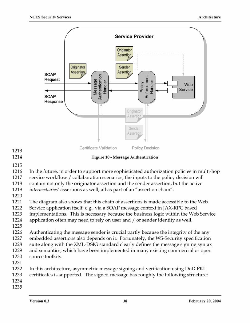
NCES Security Services Architecture
Version 0.3 38 February 20, 2004
Service ProviderService Provider
WebService
WebService
Mes
sage
Auth
entic
atio
nH
andl
er
Mes
sage
Auth
entic
atio
nH
andl
er
SOAPRequest
SOAPResponse
Polic
yEn
forc
emen
tH
andl
er
Polic
yEn
forc
emen
tH
andl
erCertificate Validation Policy Decision
OriginatorAssertion
SenderAssertion
OriginatorAssertion
SenderAssertion
OriginatorAssertion
Service ProviderService Provider
WebService
WebService
WebService
WebService
Mes
sage
Auth
entic
atio
nH
andl
er
Mes
sage
Auth
entic
atio
nH
andl
er
SOAPRequest
SOAPResponse
Polic
yEn
forc
emen
tH
andl
er
Polic
yEn
forc
emen
tH
andl
erCertificate Validation Policy Decision
OriginatorAssertion
SenderAssertion
OriginatorAssertion
SenderAssertion
OriginatorAssertion
1213 Figure 10 - Message Authentication 1214
1215 In the future, in order to support more sophisticated authorization policies in multi-hop 1216 service workflow / collaboration scenarios, the inputs to the policy decision will 1217 contain not only the originator assertion and the sender assertion, but the active 1218 intermediaries’ assertions as well, all as part of an “assertion chain”. 1219 1220 The diagram also shows that this chain of assertions is made accessible to the Web 1221 Service application itself, e.g., via a SOAP message context in JAX-RPC based 1222 implementations. This is necessary because the business logic within the Web Service 1223 application often may need to rely on user and / or sender identity as well. 1224 1225 Authenticating the message sender is crucial partly because the integrity of the any 1226 embedded assertions also depends on it. Fortunately, the WS-Security specification 1227 suite along with the XML-DSIG standard clearly defines the message signing syntax 1228 and semantics, which have been implemented in many existing commercial or open 1229 source toolkits. 1230 1231 In this architecture, asymmetric message signing and verification using DoD PKI 1232 certificates is supported. The signed message has roughly the following structure: 1233 1234 1235

NCES Security Services Architecture
Version 0.3 39 February 20, 2004
SOAP Envelope
SOAP Header
<Sender X.509 Certificate>
<Timestamp>
<User SAML Assertion>
WS-Security Header
SOAP Body
<Service Request>
<Digital Signature>
WS-Addressing Headers
<Message ID><Message ID>
( : Covered by the signature)
SOAP Envelope
SOAP Header
<Sender X.509 Certificate>
<Timestamp>
<User SAML Assertion>
WS-Security Header
SOAP Body
<Service Request>
SOAP Body
<Service Request>
<Digital Signature>
WS-Addressing Headers
<Message ID><Message ID>
( : Covered by the signature) 1236
Figure 11 - Signed SOAP Message 1237
1238 As shown in Figure 11, the message sender’s signature covers both the header elements 1239 (except the signature itself) AND the SOAP body, making sure that none may be 1240 tampered or substituted in transit. 1241 1242 This architecture hereby defines the following technical processing rules that 1243 implementations need to follow to ensure interoperability among services. These rules 1244 are based on the WS-Security core spec, the SAML spec, and the proposed WS-Security 1245 SAML Interoperability Scenarios draft document [WSS-SAML-I]. (Note: The following 1246 subsections are aimed at a technical audience and may be safely skipped for a high level 1247 understanding of the architecture.) 1248 1249 7.2.1 Message Sender Processing Rules 1250
1251 The following rules apply to the message sender: 1252 1253
NCES Security Services Architecture
Version 0.3 40 February 20, 2004
1. The SOAP header MUST contain a WS-Addressing message ID element (i.e. 1254 <wsa:MessageID>) that contains a globally unique ID (e.g., randomly 1255 generated) for this SOAP message. This element is included here to help prevent 1256 replay attacks. The message ID element MUST contain the 1257 mustUnderstand=“1” attribute. 1258
2. The Security header MUST contain the mustUnderstand=“1” attribute. 1259
3. The Security header MUST contain a <wsse:BinarySecurityToken> that 1260 contains the message sender’s X.509v3 certificate*. The valueType attribute of 1261 the binary token must be “wsse:X509v3”. 1262
4. (For request messages only) When this message is sent on behalf of another 1263 principal, the Security header MUST contain the SAML assertion as defined in 1264 section 7.1. 1265
5. The Security header MUST contain a timestamp (i.e. <wsu:Timestamp>) as 1266 defined in the WS-Security spec. The timestamp MUST contain a 1267 <wsu:Created> element that records the message creation time relative to the 1268 sender’s clock. The timestamp MAY also contain a <wsu:Expires> element 1269 that represents the expiration of the message. As specified in WS-Security SOAP 1270 Message Security 1.0 document Section 10, all timestamps MUST be in the UTC 1271 format. This architecture further recommends that all timestamps SHOULD 1272 have the resolution of milliseconds. 1273
6. The SignatureMethod MUST be RSA-SHA1. The DigestMethod MUST be 1274 SHA-1. The CanonicalizationMethod MUST be Exclusive Canonicalization. 1275
7. The signature MUST contain references to the following elements using relative 1276 URI: 1277 <wsa:MessageID> 1278
<wsse:BinarySecurityToken> 1279
<saml:Assertion>, if present 1280 <wsu:Timestamp> 1281
<soap:Body> 1282
8. The KeyInfo element MUST contain a security token reference to the sender’s 1283 X.509 certificate contained in the <wsse:BinarySecurityToken> element. 1284
1285 Please refer to the respective specifications for more syntax and implementation details. 1286 1287 Appendix A.2 contains a sample XML listing of a properly signed SOAP message. 1288 1289 * Note that in the future, this will be relaxed to include any standard referencing mechanisms to the certificate, so that the
certificate need not be passed in every message.

NCES Security Services Architecture
Version 0.3 41 February 20, 2004
7.2.2 Message Recipient Processing Rules 1290 1291 The following rules apply to the message recipient: 1292
1. The signed elements defined above MUST be verified against the signature using 1293 the specified algorithms and transforms and the public key from the sender’s 1294 certificate. 1295
2. The sender’s X.509 certificate MUST be validated. The validation may include, 1296 but not limited to, (1) it has not expired; (2) its CA chain can be validated against 1297 the trusted root; and (3) it has not been revoked based on checking the CRLs. 1298 Note that the handler may offload part or all of the certificate validation tasks to 1299 an external Certificate Validation Service, which is further discussed in Section 1300 10.2. 1301
3. The handler MUST check the Message ID for uniqueness in order to detect replay 1302 attacks. The handler SHOULD cache the Message ID for a configurable period of 1303 time. When message freshness is checked (see below), this period need not be 1304 longer than the freshness period. 1305
4. The handler SHOULD also check the timestamps for message freshness and 1306 discard messages with excessive delays. If the expiration timestamp is present, 1307 the handler SHOULD discard the message if it has passed the expiration. If the 1308 expiration timestamp is not present, the handler SHOULD use a “freshness” 1309 period instead and discard the message if the message creation timestamp is 1310 older than this period. The freshness period SHOULD be configurable by the 1311 recipient. For example, 5 minutes may be a good default value for interactive 1312 scenarios, but it may be considerably longer if asynchronous messaging 1313 transport or long network latencies are involved. As stated in the WS-Security 1314 spec, “The recipient MUST make an assessment of the level of trust to be placed 1315 in the requestor's clock.” To perform this step, it is RECOMMENDED that the 1316 machine clocks be synchronized (e.g., using the Network Time Protocol (NTP)). 1317
5. (For request messages only) The end user assertion element, if found in the request 1318 message, MUST be validated against standard SAML processing rules unless the 1319 service provider does not rely on it for authorization decisions. In addition, the 1320 issuer of the assertion SHOULD be checked against an “issuers list” in the trust 1321 domain. The implementation of this check may depend on the domain’s 1322 administrative policies. At the enterprise level, for example, the issuer may be 1323 required to be a valid and registered resource in the enterprise UDDI registry. 1324
6. (For request messages only) When the message signature is validated, the handler 1325 MUST create a new SAML authentication assertion for the message sender. The 1326 assertion MUST follow the rules defined in Section 7.1. 1327
7. (For request messages only) The message handler MUST make the sender’s 1328 authentication assertion and the end user’s assertion (if present) available to the 1329 Web Service application, either via a SOAP message context or in an API form. 1330
1331

NCES Security Services Architecture
Version 0.3 42 February 20, 2004
8. AUTHORIZATION 1331
8.1 Authorization Architecture 1332
Authorization is the means for ensuring that only properly authorized principals are 1333 able to access resources within a system. As defined previously, principals are actors 1334 within the system on whose behalf actions are taken. Principals can be human (a user) 1335 or machine (a system, service, or software process). It is worth noting that systems, 1336 services, and software processes may also be resources, and as such can exist as 1337 elements on both sides of an authorization request. For example, a service (principal) 1338 can request the invocation of another service (resource). Depending on the resource, 1339 the types of actions that are possible will also vary. Create, read, update, and delete are 1340 typical actions for a data resource. Start, stop, pause, and resume are actions that have 1341 no meaning in the context of a data resource, but are quite reasonable for a software 1342 process. For Web Services, actions are operations on the service as defined in its WSDL, 1343 and are therefore service-specific. 1344 1345 All authorization inquiries have the same general form: Can {Principal X} perform 1346 {Action Y} on {Resource Z}? Authorization policy is the means for answering these 1347 inquiries. To be more precise, an authorization policy is a set of rules that can be 1348 evaluated in response to a request, to arrive at an authorization decision. Policies 1349 historically have taken many forms, from access control list (ACL) based to role based; 1350 they may be modeled quite differently from one system to another. Policies are an 1351 important topic and will be discussed in depth in Section 9. 1352 1353 A solid authorization architecture, however, is concerned not just with policies. Rather, 1354 it covers the whole set of components, tools, and data that allows authorization 1355 decisions to be made and enforced. The goal of well-defined authorization architecture 1356 is to be flexible and extensible enough to accommodate a variety of principals, 1357 resources, actions and policies so that a wide range of business use scenarios and 1358 stakeholder requirements may be supported. 1359 1360 Figure 12 below is a diagram of a generic authorization architecture that is adopted by 1361 this security architecture. Since the primary focus of this architecture is to provide 1362 authorization for the invocation of services, the diagram is tailored to that discussion. 1363 Therefore, the Policy Enforcement Point (PEP) is depicted between a service Consumer 1364 and a service Provider. The general framework, however, is equally valid for other 1365 authorization needs. The primary difference would be the location of Policy 1366 Enforcement and Policy Decision Points. 1367 1368

NCES Security Services Architecture
Version 0.3 43 February 20, 2004
PrincipalAttributes
AuthorizationPolicies
Consumer Provider
Policy DecisionPoint (PDP)
Policy Admin.Service
Policy Enforcement Point (PEP)
Identity Mgmt.Service(s)
Request for Service Request for Service
Resource AttributeService(s) Environment
AttributeService(s)
ResourceAttributes Environment
Attributes
Attribute Admin. Services
LEGENDSvc MessageData Flow
ServiceRepository
To Be Developed
Security ServicesLayer
SecurityManagement Layer
Policy RetrievalService
Principal AttributeService(s)
1369 Figure 12 - Authorization Architecture 1370
1371 The PEP is responsible for requesting authorization decisions and enforcing them. In 1372 essence, it is the point of presence for access control and must be able to intercept 1373 service requests between consumers and providers. For conceptual clarity, the diagram 1374 depicts the PEP as a single point. Physically, however, the PEPs would more likely be 1375 distributed throughout the system. It is also valid to have more than one PEP on a 1376 single message path. For instance, if the PEP was integrated as part of an application 1377 service gateway (perhaps within a firewall), it is quite reasonable to encounter more 1378 than one gateway, and therefore more than one PEP, between a consumer and a 1379 provider. The most important security engineering consideration for the 1380 implementation of a PEP is that the system must be designed such that the PEP cannot 1381 be bypassed in order to invoke a protected service. 1382 1383

NCES Security Services Architecture
Version 0.3 44 February 20, 2004
8.2 Two Approaches for Making Policy Decisions 1384
Within the NCES architecture, each provider will incorporate an inbound SOAP 1385 message handler that will act as the PEP for all service invocations (see Figure 7 above). 1386 As discussed previously, the consumer will digitally sign all service requests such that 1387 the handler can verify the integrity of the message and authenticate the identity of the 1388 consumer. Once the message is verified, the handler, as the PEP, needs to make an 1389 authorization decision request to the PDP. Depending on its implementation 1390 preference, the service provider may use two approaches to perform the PDP function: 1391 1392
1. Use an external PDP. 1393 1394 Under this approach, the handler will formulate an Authorization Decision Query 1395 message to the Policy Decision Service (PDS), in accordance with the SAML Protocol 1396 (SAML-P) 1.1 standard. The handler will place any SAML assertions that were 1397 embedded within the header of the original message into the SAML-P Authorization 1398 Decision Query as <evidence> elements. Now acting as a consumer, the handler 1399 will digitally sign the query message with its digital identity before sending it to the 1400 PDS, similar to the process described in Section 7.2. Step 3 in Figure 6 illustrates this 1401 approach. An actual example of the SAML query (without the digital signature for 1402 simplicity) is shown in Appendix A.3. 1403 1404 Authorization decision queries sent to the PDP MUST adhere to the following 1405 processing rules: 1406 1407
The query MUST specify the resource being accessed, using the Web Service’s 1408 QName as defined in its WSDL; 1409
The query MUST specify the requested action on the resource, which is the Web 1410 Service operation; 1411
If the request to the service provider was issued on an originator’s behalf*, the 1412 query’s <subject> element MUST carry the originator’s identifier, and the 1413 originator’s assertion MUST be added as the supporting <evidence>†; 1414
Otherwise, the query’s <subject> element MUST carry the (immediate) sender’s 1415 identifier, and the assertion created by the message authentication handler for 1416 the service consumer MUST be added as <evidence>. 1417
1418 Note that in this release, the policy decisions are based on one and only one 1419 principal. That is, if the query is on an originator’s behalf that is different from the 1420
* The originator may or may not be the end user, see Section 6.2 † The query MAY also contain additional attributes regarding principals. This alternative allows for the possibility that
principal attributes may be obtained prior to making an authorization decision query.

NCES Security Services Architecture
Version 0.3 45 February 20, 2004
immediate sender, the sender principal is ignored in the decision process. In the 1421 future, the decision may be further based on the principals of the sender as well as all other 1422 intermediaries involved in the invocation chain (see the Future Work section for more 1423 discussions on this topic). 1424 1425 Upon receiving the authorization decision query, the PDS will parse it to determine 1426 the resource and action being requested. It will use this information to retrieve the 1427 appropriate policy from the Policy Retrieval Service (note: depending on whether or not 1428 the policy services are collocated, PDS may choose to directly retrieve policies from the policy 1429 store; the actual choice is up to the implementer). 1430 1431 Additionally, the PDS may need to retrieve additional principal, resource, and/or 1432 environment attributes in order to evaluate the policy. As shown in Figure 6, the 1433 attributes may be retrieved from the respective Attribute Services. 1434 1435 After the policy is evaluated, the result is rendered as either Permit, Deny, or 1436 Indeterminate, in the form of a SAML Authorization Decision Assertion. The 1437 assertion is returned to the requesting PEP using a standard SAML Protocol 1438 response message. This is shown as Step 4 in Figure 6 with an XML example in 1439 Appendix A.4. 1440
1441 2. Perform the PDP function locally. 1442 1443 Alternatively, the service Provider could choose to deploy a local PDP. In this case 1444 the PEP and PDP are essentially combined within a message handler, making the 1445 SAML query to the PDS unnecessary, but the policy evaluation process remains the 1446 same. 1447 1448 To enforce enterprise policies, the PEP+PDP message handler will need to retrieve 1449 the appropriate policy from the Policy Retrieval Service, as well as necessary 1450 principal attributes from the Principal Attribute Service, just like the way PDS does 1451 it. The policy is returned using the standard XACML syntax. This is shown as Step 1452 3-alt. in Figure 6 and an example of a XACML policy is listed in Appendix A.5. 1453 1454
The two approaches both have advantages and disadvantages. The external PDP 1455 relieves the service provider from the complexities of policy evaluation and policy 1456 retrieval, but an internal PDP may offer better performance and availability due to tight 1457 integration of PEP and PDP. The actual choice between an external vs. local PDP 1458 depends on the service provider as well as the trust domain policies it is required to 1459 satisfy; in fact the trust domain may have a mix of both approaches among different 1460 providers. 1461 1462

NCES Security Services Architecture
Version 0.3 46 February 20, 2004
Regardless of the two approaches used, a service provider may need to implement 1463 additional security checks by itself. For example, a data service may need to filter a 1464 large number of data objects based on the consumer’s privileges before returning them 1465 in the SOAP response. This would be too inefficient for the PEP to do, as it involves 1466 examining the SOAP message payloads. In this scenario, the Web Service retrieves 1467 relevant principal attributes from the Principal Attribute Service as necessary, queries 1468 the Policy Retrieval Service to retrieve the relevant policy rules (in XACML syntax), and 1469 then applies the policies on top of the service level policy enforcement the message 1470 handler. 1471 1472 8.3 Policy Decision Implementation Considerations 1473
No matter where it is located, the PDP may find it necessary to obtain more attributes to 1474 perform the policy evaluation and render a decision. Three possible processing options 1475 are described below: 1476 1477
1. The PDS could immediately retrieve all attributes that are available from each of 1478 the attribute services prior to evaluating the policy in any fashion. Once all 1479 attributes have been retrieved, the policy is evaluated and the decision is 1480 rendered as Permit, Deny, or Indeterminate. 1481
2. The PDS could parse the policy inputs and determine whether all of the 1482 necessary attributes have been obtained. If not, the PDS could then initiate 1483 attribute requests to the appropriate attribute services to retrieve the needed 1484 information. Once all necessary attributes have been retrieved, the policy is 1485 evaluated and the decision is rendered as Permit, Deny, or Indeterminate. If any 1486 of the necessary attributes could not be retrieved, the decision is rendered as 1487 Indeterminate immediately. 1488
3. The PDS could attempt to evaluate the policy with the information it already 1489 has. If a Permit or Deny outcome is reached, the decision has been rendered. If 1490 the outcome is Indeterminate, the PDS would then initiate attribute requests to 1491 the appropriate attribute services – as specified in option 2. 1492
1493 The choice of options will not impact the ultimate result of the policy evaluation. The 1494 choice is fundamentally an implementation decision that should be made based on 1495 performance optimization. The optimal choice will depend on the profile of 1496 authorization policies within a given system environment. One important 1497 consideration to be made is whether the PDS will support the Indeterminate decision 1498 result. The Indeterminate result is defined in the SAML standard as a method for a 1499 SAML authorization authority to positively affirm that it is unable to render a decision. 1500 Some reasons for why this result could occur include, a) the PDS cannot locate a policy 1501 for the specified resource within the domain’s Authorization Policy repository, b) one 1502 or more attribute values needed to evaluate the policy could not be retrieved, c) the PEP 1503 that sent the query is not recognized as a PEP within the domain, etc. Regardless of the 1504

NCES Security Services Architecture
Version 0.3 47 February 20, 2004
reason, the PDS MAY be configured to provide a Deny result in these cases. In this way, 1505 the PDS can remove any ambiguity on the part of the PEP for how to enforce the 1506 decision. 1507 1508 Attribute Services are supporting services to the PDS. As discussed they provide 1509 information relative to Principals, Resources, and the trust domain Environment. As 1510 the name implies, Principal attributes are bound to a principal identity and could 1511 include values such as identity, aliases, email address, roles, communities of interest, 1512 clearance, formal access approvals, citizenship, organizational designator, office, phone 1513 number, etc. Resource attributes are those attributes associated with resource objects 1514 and could include a wide variety of metadata values such as resource identifier, type, 1515 provider, security label, hash or checksum, keywords, etc. Environment attributes are 1516 those attributes that are not associated with a principal or resource, but are still useful 1517 as part of an authorization policy. Examples of environment attributes could include 1518 values such as maximum security level, hours of operation, current time, geographic 1519 location, time zone, etc. These values may be common across a trust domain and 1520 therefore not treated as resource attributes. 1521 1522 Attribute query messages will be formulated in accordance with the SAML-P spec. 1523 Likewise, each attribute service will respond in the form of a SAML attribute assertion 1524 contained in a SAML Protocol response. 1525 1526 It is important to note that, attributes that are relevant to the policy decision process are 1527 sometimes sensitive information that needs to be protected. For example, it is critical to 1528 prevent principal attributes from being harvested by a rogue PDP for malicious 1529 purposes (e.g. data mining on users). Future versions of this architecture will address 1530 this issue. 1531
1532

NCES Security Services Architecture
Version 0.3 48 February 20, 2004
9. AUTHORIZATION POLICIES 1532
In the previous section, a normative authorization architecture was defined, with clearly 1533 defined component boundaries and standards-based message exchange mechanisms for 1534 policies and policy decisions. However, as mentioned earlier, the underlying 1535 authorization policies, managed by the Policy Administration Service, could take many 1536 forms and may differ from domain to domain or from one resource type to another. For 1537 this reason, it is the intention of this document to keep the policy management aspect of 1538 the authorization architecture non-normative, allowing domain-specific access control 1539 models to be plugged-in. In this section, a basic Role Based Access Control (RBAC) 1540 model is described, that SHOULD be adopted for authorizing Web Service invocations. 1541 In the future, this model may evolve to a broader attribute-based model that can 1542 accommodate policy decisions based on many attributes including roles. 1543 1544 9.1 The RBAC Model 1545
To reiterate, authorization policy is the means for answering the query “Can {Principal 1546 X} perform {Action Y} on {Resource Z}? “ An access control list or ACL is a simple form 1547 of authorization policy found in most file management systems today. An ACL, for 1548 example, might specify that an explicit list of users may read a particular file. This is an 1549 example of identity based access control (IBAC). But access lists are difficult to 1550 maintain. Thus, other approaches have been devised such as role based access control 1551 (RBAC), where the identity of individual users is replaced in authorization policies by a 1552 role. In this way, roles can be assigned or unassigned to users without needing to 1553 modify the access policies themselves. 1554 1555 The RBAC model has the following benefits: 1556 1557
Compared with IBAC, RBAC adds levels of indirection between identities and 1558 resources. Because permissions no longer need to be repeatedly assigned to 1559 individual users, RBAC scales much better and significantly reduces 1560 administration overheads. 1561 RBAC is highly flexible and can have many variants with sophisticated features 1562
(e.g. role hierarchies, dynamic separate of duty constraints), making it possible to 1563 meet more complex business needs. 1564 Compared with Mandatory Access Control (MAC) policies that are based on 1565
coarse labeling of subjects and objects, RBAC provides more granularity of 1566 assigning permissions, so that users are not granted (and hence use) more access 1567 than they need. 1568 RBAC maps intuitively to the way business roles and responsibilities are 1569
managed, and is therefore easy to understand and use. 1570 1571

NCES Security Services Architecture
Version 0.3 49 February 20, 2004
Because of these benefits, RBAC has become the prevalent access control model today 1572 and widely deployed a wide variety of systems and products. Its inherent flexibility, 1573 however, also resulted in the lack of general agreement on its definition and features, 1574 which has created uncertainty and confusion of its usage and meaning. Recently, a 1575 voluntary RBAC standard has been proposed by the National Institute of Standards and 1576 Technologies (NIST) to resolve this situation. The standard defines a “reference model” 1577 that formalizes RBAC features, and then describes the functional specifications of those 1578 features [RBAC]. 1579 1580 For access control of Web Service invocations, we hereby describe a simple RBAC 1581 model that is consistent with the Core RBAC Reference Model defined in the NIST 1582 standard. The model is shown in Figure 13 below. 1583 1584 1585
PrincipalsPrincipals RolesRoles
PermissionsPermissions
ActionsActions ResourcesResources
SecurityContexts
SecurityContexts
Many-to-manyrelationship
One-to-manyrelationship
To bedevelopedLEGEND
PrincipalsPrincipals RolesRoles
PermissionsPermissions
ActionsActions ResourcesResources
SecurityContexts
SecurityContexts
Many-to-manyrelationship
One-to-manyrelationship
To bedevelopedLEGEND Many-to-many
relationshipOne-to-manyrelationship
To bedevelopedLEGEND
1586 Figure 13 - Basic RBAC Model 1587
1588 Technically, roles in this diagram are a means for many-to-many relationship between 1589 principals and permissions. However, it is important to note that roles should not be 1590 viewed simply as a technical mechanism for easier grouping of users or permissions. 1591 They should map to business meanings and responsibilities. As defined in the NIST 1592 standard, a role should be “a job function within the context of an organization with 1593 some associated semantics regarding the authority and responsibility conferred on the 1594 user.” In the NCES context, depending on whether the trust domain is an enterprise (or 1595 COI, or local) domain, enterprise (or COI, or local) roles SHOULD be clearly defined 1596 and centrally managed by the domain. 1597 1598 Permissions in the above model represent approval to perform an action on one or more 1599 resources. Note that a resource (e.g. a Web Service) usually has multiple actions (e.g. 1600

NCES Security Services Architecture
Version 0.3 50 February 20, 2004
service operations defined in WSDL), while the same action may be applicable to 1601 multiple resources. For example, the “getAttribute” operation may be defined for 1602 Principal, Resource, and Environment Attribute Services. 1603 1604 In the near future two additional features may be added to this basic model: 1605 1606
1. Principal hierarchies. In a large scale business environment such as the DoD 1607 enterprise, there could be millions of users and other types of principals. For 1608 ease of administrative duties hierarchical groups of principals MAY be defined 1609 so that the number of principals assigned to a role doesn’t get out of control. For 1610 example, if 50 contractors from company A and 50 contractors from company B 1611 need to be assigned the “Demo User” role, adding 100 principals in the role 1612 membership list could be a very tedious job. It would be more convenient and 1613 more manageable to create two groups, “Company A contractors” and 1614 “Company B Contractors”, and then add the two groups under the role 1615 membership. When doing so, however, it is imperative to maintain the clear 1616 distinction between principal groups and roles. Principal groups are purely 1617 convenience constructs and should not have authorities and responsibilities 1618 directly attached to them. 1619
2. Context activated roles, also known as “session roles” in the NIST standard. 1620 Sessions are common in an enterprise environment. For example, an end-user 1621 logging in to a portal server from a thin client usually has a session or multiple 1622 sessions that last for a certain period of time. In the NCES architecture, sessions 1623 are generalized into a broader concept of security contexts, which not only exists 1624 in edge applications but spans service providers as well. Unlike user sessions 1625 which are primarily authentication oriented (so that users do not have to log in 1626 for every HTTP request), security contexts also have important authorization 1627 uses. In particular, it is sometimes desirable to allow only a subset of a user’s 1628 roles to exist under a certain context. For example, when a DoD employee works 1629 in the office, all his or her roles are activated to access the authorized business 1630 functions. When logging in from home, however, the employee may still be able 1631 to read news on the web portal, but the “Procurement Manager” role will not be 1632 activated to ensure that sensitive information cannot be accessed from 1633 unprotected computers. As shown in Figure 14, a principal may be associated 1634 with a set of security contexts and a security context may be associated with a 1635 subset of activated user roles. This feature provides further expressive power to 1636 the RBAC model. 1637
1638 Under this model, authorization policies are naturally represented as rules that assign 1639 permissions to roles, as shown in Figure 14 below: 1640 1641

NCES Security Services Architecture
Version 0.3 51 February 20, 2004
PrincipalsPrincipals RolesRoles
PermissionsPermissions
ActionsActions ResourcesResources
SecurityContexts
SecurityContexts
Many-to-manyrelationship
One-to-manyrelationship
OptionalfeaturesLEGEND
PoliciesPoliciesPolicy SetsPolicy Sets
Assigned to
PrincipalsPrincipals RolesRoles
PermissionsPermissions
ActionsActions ResourcesResources
SecurityContexts
SecurityContexts
Many-to-manyrelationship
One-to-manyrelationship
OptionalfeaturesLEGEND Many-to-many
relationshipOne-to-manyrelationship
OptionalfeaturesLEGEND
PoliciesPoliciesPolicy SetsPolicy Sets
Assigned to
1642 Figure 14 - RBAC Based Policies 1643
1644 As shown in the diagram, policies MUST be associated with roles, not directly with 1645 principals. Generally, for clarity and granularity sake, a policy SHOULD be assigned to 1646 one role. The policy MAY contain permissions for multiple resources, though. The 1647 actual XACML exchange format of the policy may vary depending on the actual query. 1648 For instance, if a XACML query is concerned with a specific action on a specific 1649 resource, then only that part of the policy concerning the requested action may be 1650 returned. 1651 1652 9.2 Looking Ahead: the Attribute Based Approach 1653
Through the use of multiple roles, policies can be formed that satisfy more complex 1654 business needs. However, for even more complex needs, roles alone are inadequate to 1655 provide the desired flexibility. Within the federal government, particularly within the 1656 DoD and Intelligence communities, access control must also be based on the sensitivity 1657 of information. Whereas IBAC and RBAC are primarily discretionary access control 1658 (DAC) mechanisms, they are not best suited to address these mandatory access control 1659 (MAC) requirements. 1660 1661 The goal of a well-engineered authorization framework is to be flexible enough to 1662 accommodate a variety of principals, resources, actions and policies such that it is 1663 extensible to a wide range of business use scenarios. In response to more complicated 1664

NCES Security Services Architecture
Version 0.3 52 February 20, 2004
business needs, authorization mechanisms have been migrating, slowly but inexorably, 1665 towards a more flexible attribute based approach. Since identities and roles can be 1666 viewed as nothing more than attributes of principals, both IBAC and RBAC can be 1667 wholly absorbed into an attribute-based mechanism. Attribute-based authorization 1668 policies have some distinct advantages over other approaches. First, an attribute-based 1669 approach recognizes from its inception that a flexible access control policy cannot be 1670 locked into evaluating only one dimension of a principal (such as an identity or role). 1671 For example, in order to provide proper controls for accessing classified information it 1672 is necessary to consider various other principal attributes such as clearance level, formal 1673 access approvals, or citizenship. Second, an attribute-based approach takes into 1674 consideration that there are other attributes that are relevant to authorization policies 1675 besides those associated with a principal, such as resource or environment attributes. 1676 1677 The attribute-based approach will be explored in more detail in future versions of this 1678 document. 1679 1680
1681

NCES Security Services Architecture
Version 0.3 53 February 20, 2004
10. OTHER TOPICS 1681
10.1 Message Confidentiality 1682
When required to counter identified threats, two general options are available to 1683 achieve confidentiality for service messages: 1684 1685
Rely on underlying communications security: Unencrypted SOAP messages 1686 may be acceptable if the underlying communications infrastructure provides 1687 adequate confidentiality to protect transmissions. Confidentiality can be 1688 provided at several layers of the communications stack; transport layer (e.g., SSL 1689 / TLS), network layer (e.g., IPSEC, inline network encryptors), and physical / 1690 link layer (e.g., link encryptors). 1691 Encrypted SOAP messages: Message encryption is recommended when 1692
transmission confidentiality is not provided. When XML-Encryption is used, the 1693 WS-Security processing logic within the SDK message handlers may also be 1694 responsible for encrypting and decrypting the SOAP message. 1695
1696 These options are not mutually exclusive and therefore may be employed together as 1697 part of a defense-in-depth strategy. Using at least one of these options is recommended. 1698 Due to performance concerns involved in message level encryption, the transmission 1699 confidentiality techniques may be preferable in most situations in the near term. If 1700 message encryption is not employed, XML encryption may still be employed at the 1701 implementer’s discretion to provide confidentiality for elements within the body of a 1702 message (data confidentiality). 1703 1704 10.2 Use of DoD PKI 1705
As described earlier, the Credential Management Services group of services provides 1706 the primary interface to the DoD PKI. The DoD PKI consists of the products and 1707 services that provide and manage X.509 certificates for public-key cryptography. 1708 Specific services provided by the DoD PKI include: 1709 1710
Key generation, storage, and recovery (encrypt / decrypt keys) 1711
Certificate generation, update, renewal, rekey, and distribution 1712
Certificate Revocation List (CRL) generation and distribution 1713
Directory management of certificate related items 1714
Certificate token initialization, programming, and management (NIPRnet) 1715
1716 Since the Certification Validation Service (CVS) is the only service offered in the current 1717 architecture that is related to credential management, a few CVS related 1718 implementation issues are discussed below. 1719
NCES Security Services Architecture
Version 0.3 54 February 20, 2004
10.2.1 Revocation Status Checking vs. Full Certificate Validation 1720 1721 As mentioned earlier in Section 4.5, a client (message handler) may delegate part or 1722 all of the certificate validation tasks to the CVS. Two reasonable alternatives are: (1) 1723 use the CVS to perform certificate revocation status checking, in which case the CVS 1724 functions similar to an OCSP responder, or (2) use the CVS to perform the entire 1725 certificate path validation. Both alternatives provide significant benefit to the 1726 message handler. By offloading revocation status checking to the CVS, the handlers 1727 do not need to download, store, maintain, and process certificate revocation lists 1728 (CRLs) for the entire PKI. Distribution of CRLs within an enterprise can be a very 1729 difficult and costly process. Within the DoD PKI, this process is further complicated 1730 by the extremely large size of many DoD CRLs. 1731 1732 When the CVS performs the entire certificate validation process, the message 1733 handler is only responsible for verifying the digital signature of the message. The 1734 handler is relieved of the complexities of X.509 processing (e.g., certificate path 1735 construction, name subordination checking, full certificate parsing, certificate 1736 extension processing, as well as revocation status checking). This handler is also 1737 relieved of maintaining or locating many (or perhaps all – see 10.2.2) of the CA 1738 certificates and CRLs that are needed to build and validate certificate paths. In 1739 either case, the message handler (as the relying party) must be able to authenticate 1740 the CVS responses so that it can verify that they were sent from a responder that it 1741 trusts. This is most easily satisfied using signed responses, although not without 1742 some complications (see 10.2.2). 1743 1744 Under the current architecture, service providers and consumers are REQUIRED to perform 1745 certificate path validation, but MAY rely on the CVS to provide certificate revocation status 1746 checking. Requests to and responses from the CVS MUST be in the form of a signed SOAP 1747 message as discussed in Section 7.2. 1748 1749 The use of CVS for full certificate path validation is not currently supported, but 1750 remains an option under consideration for future releases. 1751
1752 10.2.2 CVS Certificate Options 1753
1754 In both cases described in the previous section, the CVS serves as a trust responder, 1755 whereby a message handler delegates some portion of its trust processing to the 1756 CVS, which it authenticates through a signed response. As such, the benefits are not 1757 gained without some trade-off of risk. More specifically, the message handler faces 1758 two options when authenticating the CVS response: it either chains the CVS 1759 certificate to a Root certificate, or explicitly trusts that certificate. 1760 1761 1. Chaining to the Root 1762 1763

NCES Security Services Architecture
Version 0.3 55 February 20, 2004
Without a trust responder, all end-entity certificates and CRLs are signed by either 1764 the Root CA or a subordinate CA issued from the Root. Therefore, a message 1765 handler can base its authentication on the ability to chain back to a Root certificate 1766 that it explicitly accepts as a trust anchor. With a trust responder it is possible to 1767 maintain this single trust anchor by using a certificate issued from within the PKI. 1768 However, in order to authenticate responses, the message handler would still need 1769 to perform certificate path validation including revocation checking for the 1770 responder. As a result, the message handler would need to maintain certificates for 1771 the Root CA and the subordinate CA that issued the responder’s certificate. It 1772 would also need to maintain the CRLs issued by the Root and subordinate CAs. To 1773 reduce this need, it is possible that trust responder certificates could be issued 1774 directly from the Root CA. This would be optimal from the standpoint of the 1775 message handler because responder certificates would chain directly to the Root, 1776 and only the Root CRL would be needed. However, this approach is not desirable 1777 from the standpoint of the DoD PKI for various policy and operational reasons. 1778 Moreover, since there is a potential need for many trust responders to exist across 1779 the enterprise, it would be better to issue these certificates from subordinate CAs. It 1780 is important to note that using an existing DoD CA is also not ideal due to the 1781 potentially large size of the CRL. 1782 1783 Therefore, in order to maintain the Root CA as the single trust anchor, the best 1784 overall alternative would be to establish a subordinate CA under the Root dedicated 1785 to issuing only trust responder certificates – since this would allow the CRL for this 1786 CA to remain small (relative to the other DoD subordinate CAs.) 1787 1788 2. Explicit trust of responders 1789 1790 One way to maintain the full benefits of trust responders is to have each message 1791 handler explicitly trust the responder’s certificate as a trust anchor – similar to the 1792 way a Root certificate is trusted. In this way, the message handler can directly verify 1793 response message signatures, and does not need to perform any certificate path 1794 validation or revocation status checking for the responder itself. The only 1795 operational complexity this introduces is the need to distribute and trust the 1796 responder certificates to each message handler, which makes this option very 1797 attractive. However, explicit trust is not without its drawbacks. This approach 1798 introduces additional risk to the solution and therefore lowers overall security. The 1799 risk that is introduced relates to the potential compromise of the responder’s private 1800 key. 1801 1802 Without explicit trust, the only trust anchor is the Root CA. The probability of 1803 compromising the DoD Root private key is virtually nil, since the Root CA is a 1804 standalone machine, and there are an extraordinary number of technical, physical, 1805 and procedural controls in place to prevent such a compromise. A trust responder, 1806
NCES Security Services Architecture
Version 0.3 56 February 20, 2004
by its very nature, must be connected to the network and up and running at all 1807 times. Therefore, probability of compromising the responder’s private key is 1808 substantially higher because the responder platform is susceptible to network attack. 1809 The impact of a responder compromise depends on the nature of the responder. 1810 Compromise of a revocation status responder allows an adversary to forge 1811 responses. The two potential results are a) the responder can potentially cause 1812 others to trust certificates that have been revoked by the PKI, or b) the responder can 1813 potentially cause all certificates to appear to be revoked, thus creating a denial of 1814 service. Compromise of a full certificate path validation responder is far more 1815 serious. Since the message handler delegates all validation to the responder, an 1816 adversary can cause any certificate to be trusted, regardless of its true origin or 1817 validity. This is functionally equivalent to a Root key compromise for any message 1818 handler that trusts that responder. 1819 1820 One way to mitigate this risk is to employ a hardware cryptographic module at the 1821 responder (e.g., nCipher, Chrysalis) to provide strong protection for the private key. 1822 Another mitigation could be to limit the validity period of responder certificates to a 1823 reasonable period of time (e.g., 30 days). However, this would introduce the 1824 operational burden of periodically redistributing the certificate. 1825 1826 There is no absolute requirement for the responder certificate to be issued from the 1827 PKI when using explicit trust. Since the certificate must be distributed as a trust 1828 anchor it is possible to use a self-signed certificate. However, using a certificate 1829 issued from the PKI is preferable since the distribution can be conducted in-band. 1830 Since there is no alternate means for validation of a self-signed certificate by 1831 implementers prior to installation as the trust anchor, it must be distributed via an 1832 out-of-band process. The only compelling reason to use a self-signed certificate 1833 would be if an appropriate certificate could not be obtained directly from a DoD PKI 1834 CA due to operational or policy constraints. 1835 1836 Due to the complexity and operational requirements involved in setting up special 1837 subordinate CAs for CVS, we leave the second option for further discussions. 1838 1839 In this version of the architecture, service consumers and providers are REQUIRED 1840 to explicitly trust the CVS’ certificate. They MUST validate the signed CVS 1841 responses using the pre-distributed CVS certificate. 1842
1843 10.3 Beyond Trust Domain Boundaries 1844
A new set of security challenges arise when a service consumer attempts to invoke a 1845 service in a different trust domain, largely because the consumer and provider are 1846 governed by different authentication and authorization policies. Issues to consider may 1847 include the following: 1848
NCES Security Services Architecture
Version 0.3 57 February 20, 2004
1849 Trust domain federation. A trust relationship, governed by mutually agreed-1850
upon policies, must be established between the two domains before resource 1851 access can occur. The relationship is one-way by nature, but two domains may 1852 have mutual trust by establishing two one-way relationships; 1853 Discovery of services in foreign domains. Service registries need to be aware of 1854
internal vs. external discoveries and exert different access controls on service 1855 visibility; 1856 Mechanisms for exchanging user attributes. For example, the source domain 1857
may not be willing to release all user attributes to the target domain, and may 1858 choose to attach some “public” attributes along with the authentication assertion; 1859 Federation of identities, when a principal has different identities and / or 1860
credentials in the two domains; 1861 MLS concerns, when the two domains are not at the same security level; 1862 PKI interoperability concerns, esp. if the two domains have different CA roots 1863
1864 These topics are beyond the scope of this release and will be covered in future versions 1865 of the architecture. 1866 1867
1868
NCES Security Services Architecture
Version 0.3 58 February 20, 2004
11. FUTURE WORK 1868
The following are identified as items that need to be addressed in future iterations of 1869 the architecture: 1870 1871 1. Lack of target destination in a Web Service request. 1872
1873 Because the identifier of the target service is not part of the SOAP protocol (SOAP 1874 lets underlying transport protocols such as HTTP to handle this), a Web Service 1875 request may potentially be hijacked and replayed to some other service provider 1876 that happens to support the same WSDL operation. A simple solution is to include a 1877 “target service URI” in the SOAP header, which is covered by the message 1878 signature. Currently emerging standards such as WS-Addressing [WSADDR] are 1879 addressing this problem; they be evaluated for use in this architecture in the future. 1880 1881
2. Relay of trust in service chaining. 1882 1883 As described in Section 7 and 8, a service provider’s authorization decision for an 1884 incoming service request is built on both the immediate sender of the message and 1885 the assertion of the end user on whose behalf the request is made. In the service 1886 chaining scenario, shown in Figure 8, assuming the requests are on the end user’s 1887 behalf, the sender of the message are no longer the issuer of the end user’s 1888 authentication assertion for the second and all following requests. This implies that 1889 a service provider will not accept the incoming request unless all intermediaries 1890 along the invocation path are trustworthy – that they haven’t intentionally tampered 1891 with and / or misused the original assertion. One potential risk lies in the 1892 possibility for an intermediary to hijack a valid user assertion and place that in 1893 malicious messages. This risk is not mitigated even if the original assertion is signed 1894 by the portal, because the downstream service provider still have to trust that the 1895 bindings between the assertion and the request bodies haven’t been tampered with 1896 by any of the intermediaries. 1897 1898 This problem cannot be addressed by putting a target service URI in the original 1899 SOAP request, either, because in a dynamic service collaboration environment the 1900 final target service(s) may not be known when the original request is made. 1901 1902 A possible solution is to include an “intended use” attribute in the original 1903 authentication assertion, which defines the boundary of this unit of work or business 1904 transaction, so that if the assertion is misplaced and use for some other purposes, the 1905 recipient of the message is able to detect and reject it. This approach needs to be 1906 further researched and defined. 1907 1908
3. Richer policy decision semantics. 1909

NCES Security Services Architecture
Version 0.3 59 February 20, 2004
1910 Future work in this area may include: 1911 1912
Attribute based policy models; 1913 Making policy decisions based on not just the end user identity, but also on 1914
the principals of intermediaries in the invocation path; 1915 Introducing resource and environment attributes as policy constraints; 1916 Context activated roles, as mentioned in Section 9.1; 1917 Introducing role hierarchies in the basic RBAC model; 1918 Introducing static or dynamic Separation of Duty constraints into the basic 1919
RBAC model 1920 1921
4. Security context establishment. 1922 1923 There are some proposed standards that may address this issue, such as WS-Trust, 1924 WS-SecureConversation, and WS-Federation. 1925 1926
5. Cross-trust domain service based collaboration. 1927 1928 This is a challenging problem area with a lot of topics, including identity federation, 1929 cross-domain authentication and authorization, MLS support, etc. 1930 1931
6. Content or data level security. 1932 1933 That is, how we can better protect sensitive data in a SOA environment. This is of 1934 particular relevance to content discovery services. 1935 1936
7. Integration with other net-centric enterprise services. 1937 1938 Here we need to address the integration of the Security Services with Service 1939 Discovery, Enterprise Service Management (ESM), Messaging Services, and others. 1940 1941
8. Definition of enterprise level security attributes and taxonomies. 1942 1943 Before we can exchange identity, resource, and environment attributes among 1944 service providers (including NSS providers), we need to identify and define those 1945 attributes. This is also important to cross-domain security. 1946 1947
9. Definition of enterprise auditing and logging services. 1948 1949 They are essential for accountability in a brokered trust environment, esp. in the 1950 absence of positive mandatory access controls. 1951 1952

NCES Security Services Architecture
Version 0.3 60 February 20, 2004
10. Protection of sensitive attributes. 1953 1954 Principal and resource attributes need to be protected so that they cannot be 1955 harvested for data mining or other malicious purposes. 1956 1957
11. Support for “thick” Clients. 1958 1959 In addition to end users accessing enterprise services via a web portal from a web 1960 browser (“thin” client), there are other applications that are not web-based (e.g. Java 1961 desktop applications or legacy systems), but may also need to access the services. 1962 Authentication and authorization of such SOAP requests will be addressed later. 1963 1964
1965
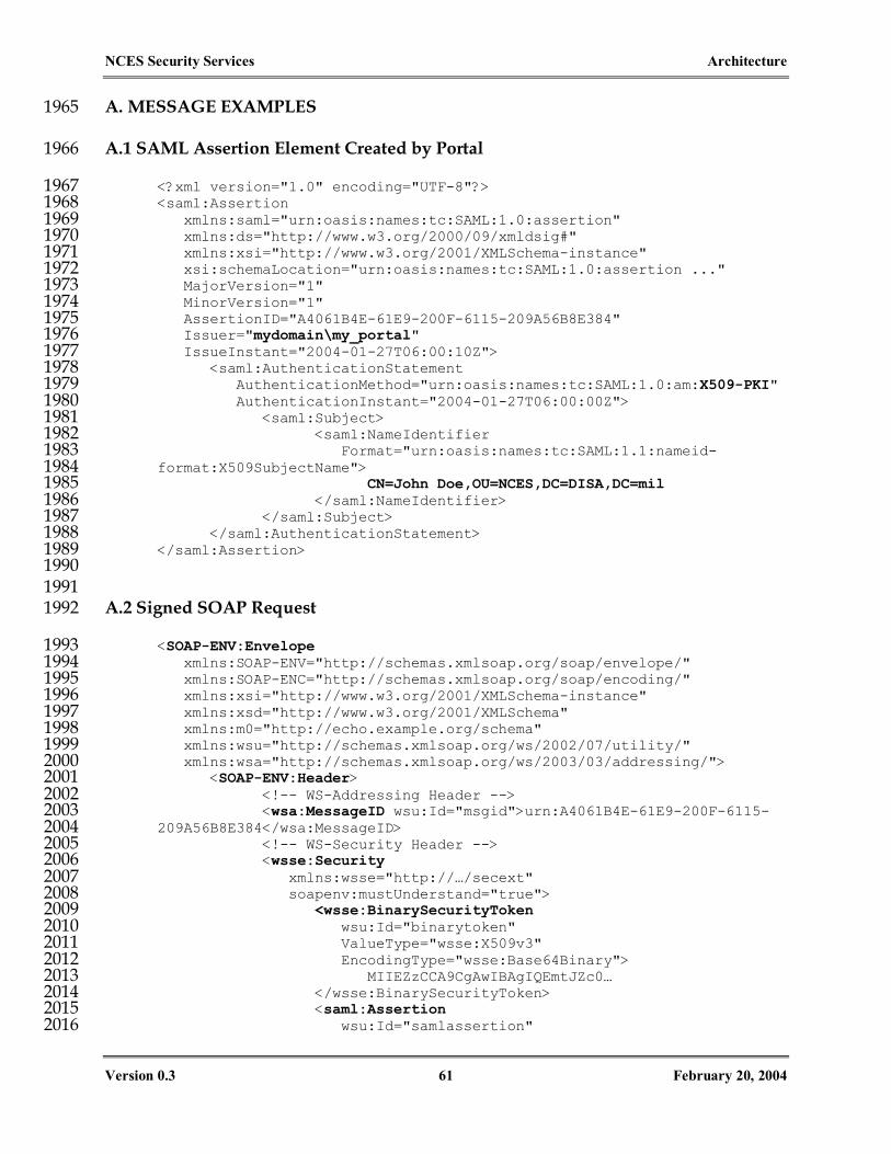
NCES Security Services Architecture
Version 0.3 61 February 20, 2004
A. MESSAGE EXAMPLES 1965
A.1 SAML Assertion Element Created by Portal 1966
<?xml version="1.0" encoding="UTF-8"?> 1967 <saml:Assertion 1968 xmlns:saml="urn:oasis:names:tc:SAML:1.0:assertion" 1969 xmlns:ds="http://www.w3.org/2000/09/xmldsig#" 1970 xmlns:xsi="http://www.w3.org/2001/XMLSchema-instance" 1971 xsi:schemaLocation="urn:oasis:names:tc:SAML:1.0:assertion ..." 1972 MajorVersion="1" 1973 MinorVersion="1" 1974 AssertionID="A4061B4E-61E9-200F-6115-209A56B8E384" 1975 Issuer="mydomain\my_portal" 1976 IssueInstant="2004-01-27T06:00:10Z"> 1977 <saml:AuthenticationStatement 1978 AuthenticationMethod="urn:oasis:names:tc:SAML:1.0:am:X509-PKI" 1979 AuthenticationInstant="2004-01-27T06:00:00Z"> 1980 <saml:Subject> 1981 <saml:NameIdentifier 1982 Format="urn:oasis:names:tc:SAML:1.1:nameid-1983 format:X509SubjectName"> 1984 CN=John Doe,OU=NCES,DC=DISA,DC=mil 1985 </saml:NameIdentifier> 1986 </saml:Subject> 1987 </saml:AuthenticationStatement> 1988 </saml:Assertion> 1989 1990
1991 A.2 Signed SOAP Request 1992
<SOAP-ENV:Envelope 1993 xmlns:SOAP-ENV="http://schemas.xmlsoap.org/soap/envelope/" 1994 xmlns:SOAP-ENC="http://schemas.xmlsoap.org/soap/encoding/" 1995 xmlns:xsi="http://www.w3.org/2001/XMLSchema-instance" 1996 xmlns:xsd="http://www.w3.org/2001/XMLSchema" 1997 xmlns:m0="http://echo.example.org/schema" 1998 xmlns:wsu="http://schemas.xmlsoap.org/ws/2002/07/utility/" 1999 xmlns:wsa="http://schemas.xmlsoap.org/ws/2003/03/addressing/"> 2000 <SOAP-ENV:Header> 2001 <!-- WS-Addressing Header --> 2002 <wsa:MessageID wsu:Id="msgid">urn:A4061B4E-61E9-200F-6115-2003 209A56B8E384</wsa:MessageID> 2004 <!-- WS-Security Header --> 2005 <wsse:Security 2006 xmlns:wsse="http://…/secext" 2007 soapenv:mustUnderstand="true"> 2008 <wsse:BinarySecurityToken 2009 wsu:Id="binarytoken" 2010 ValueType="wsse:X509v3" 2011 EncodingType="wsse:Base64Binary"> 2012 MIIEZzCCA9CgAwIBAgIQEmtJZc0… 2013 </wsse:BinarySecurityToken> 2014 <saml:Assertion 2015 wsu:Id="samlassertion" 2016
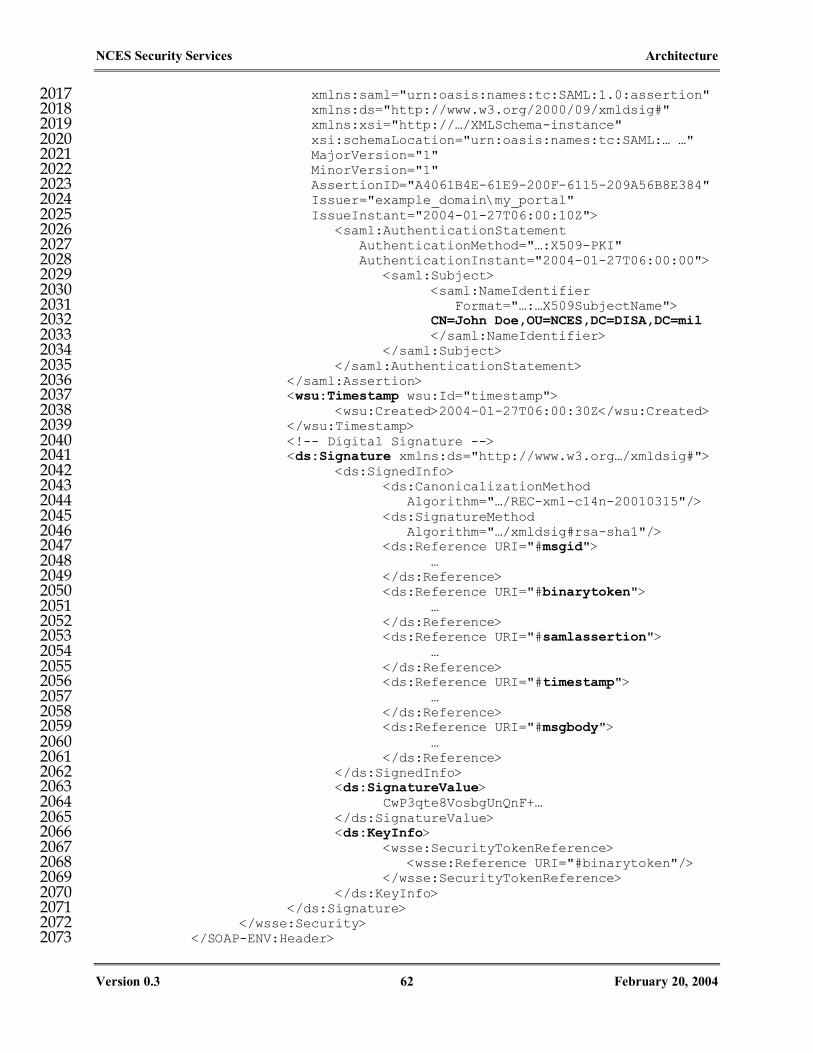
NCES Security Services Architecture
Version 0.3 62 February 20, 2004
xmlns:saml="urn:oasis:names:tc:SAML:1.0:assertion" 2017 xmlns:ds="http://www.w3.org/2000/09/xmldsig#" 2018 xmlns:xsi="http://…/XMLSchema-instance" 2019 xsi:schemaLocation="urn:oasis:names:tc:SAML:… …" 2020 MajorVersion="1" 2021 MinorVersion="1" 2022 AssertionID="A4061B4E-61E9-200F-6115-209A56B8E384" 2023 Issuer="example_domain\my_portal" 2024 IssueInstant="2004-01-27T06:00:10Z"> 2025 <saml:AuthenticationStatement 2026 AuthenticationMethod="…:X509-PKI" 2027 AuthenticationInstant="2004-01-27T06:00:00"> 2028 <saml:Subject> 2029 <saml:NameIdentifier 2030 Format="…:…X509SubjectName"> 2031 CN=John Doe,OU=NCES,DC=DISA,DC=mil 2032 </saml:NameIdentifier> 2033 </saml:Subject> 2034 </saml:AuthenticationStatement> 2035 </saml:Assertion> 2036 <wsu:Timestamp wsu:Id="timestamp"> 2037 <wsu:Created>2004-01-27T06:00:30Z</wsu:Created> 2038 </wsu:Timestamp> 2039 <!-- Digital Signature --> 2040 <ds:Signature xmlns:ds="http://www.w3.org…/xmldsig#"> 2041 <ds:SignedInfo> 2042 <ds:CanonicalizationMethod 2043 Algorithm="…/REC-xml-c14n-20010315"/> 2044 <ds:SignatureMethod 2045 Algorithm="…/xmldsig#rsa-sha1"/> 2046 <ds:Reference URI="#msgid"> 2047 … 2048 </ds:Reference> 2049 <ds:Reference URI="#binarytoken"> 2050 … 2051 </ds:Reference> 2052 <ds:Reference URI="#samlassertion"> 2053 … 2054 </ds:Reference> 2055 <ds:Reference URI="#timestamp"> 2056 … 2057 </ds:Reference> 2058 <ds:Reference URI="#msgbody"> 2059 … 2060 </ds:Reference> 2061 </ds:SignedInfo> 2062 <ds:SignatureValue> 2063 CwP3qte8VosbgUnQnF+… 2064 </ds:SignatureValue> 2065 <ds:KeyInfo> 2066 <wsse:SecurityTokenReference> 2067 <wsse:Reference URI="#binarytoken"/> 2068 </wsse:SecurityTokenReference> 2069 </ds:KeyInfo> 2070 </ds:Signature> 2071 </wsse:Security> 2072 </SOAP-ENV:Header> 2073

NCES Security Services Architecture
Version 0.3 63 February 20, 2004
<SOAP-ENV:Body wsu:Id="msgbody"> 2074 <m:echo xmlns:m="http://echo.example.org"> 2075 <m0:EchoString>Hello World</m0:EchoString> 2076 <m0:NumEchoes>1</m0:NumEchoes> 2077 </m:echo> 2078 </SOAP-ENV:Body> 2079 </SOAP-ENV:Envelope> 2080
2081 A.3 SAML-P Authorization Decision Query 2082
<?xml version="1.0" encoding="UTF-8"?> 2083 <soapenv:Envelope 2084 xmlns:soapenv="http://schemas.xmlsoap.org/soap/envelope/" 2085 xmlns:xsd="http://www.w3.org/2001/XMLSchema" 2086 xmlns:xsi="http://www.w3.org/2001/XMLSchema-instance"> 2087 <soapenv:Body> 2088 <samlp:Request 2089 IssueInstant="2004-01-31T13:00:58.287Z" 2090 MajorVersion="1" MinorVersion="1" 2091 RequestID="ID_2d10e285-42d4-4926-984e-fab8ea72d32a" 2092 xmlns:samlp="urn:oasis:names:tc:SAML:1.0:protocol"> 2093 <samlp:AuthorizationDecisionQuery 2094 Resource="urn:mydomain:HelloWorldService"> 2095 <saml:Subject 2096 xmlns:saml="urn:…:SAML:1.0:assertion"> 2097 <saml:NameIdentifier 2098 Format="…:X509SubjectName" 2099 NameQualifier="…"> 2100 CN=John Doe,OU=NCES,DC=DISA,DC=mil 2101 </saml:NameIdentifier> 2102 </saml:Subject> 2103 <saml:Action 2104 xmlns:saml="urn:…:SAML:1.0:assertion"> 2105 helloWorld 2106 </saml:Action> 2107 <saml:Evidence 2108 xmlns:saml="urn:…:SAML:1.0:assertion"> 2109 <saml:Assertion 2110 AssertionID="…" 2111 IssueInstant="…" 2112 Issuer="…" 2113 MajorVersion="1" MinorVersion="1"> 2114 <saml:Conditions 2115 NotBefore="…" 2116 NotOnOrAfter="…"/> 2117 <saml:AuthenticationStatement 2118 AuthenticationInstant="…" 2119 AuthenticationMethod="urn: 2120 oasis:names:tc:SAML:1.0:am:password"> 2121 <saml:Subject> 2122 <saml:NameIdentifier 2123 Format="…" 2124 NameQualifier="…"> 2125 CN=John Doe, … 2126 </saml:NameIdentifier> 2127 </saml:Subject> 2128

NCES Security Services Architecture
Version 0.3 64 February 20, 2004
</saml:AuthenticationStatement> 2129 </saml:Assertion> 2130 </saml:Evidence> 2131 </samlp:AuthorizationDecisionQuery> 2132 </samlp:Request> 2133 </soapenv:Body> 2134 </soapenv:Envelope> 2135
2136 A.4 SAML-P Authorization Decision Response 2137
<?xml version="1.0" encoding="UTF-8"?> 2138 <soapenv:Envelope 2139 xmlns:soapenv="http://schemas.xmlsoap.org/soap/envelope/" 2140 xmlns:xsd="http://www.w3.org/2001/XMLSchema" 2141 xmlns:xsi="http://www.w3.org/2001/XMLSchema-instance"> 2142 <soapenv:Body> 2143 <samlp:Response 2144 InResponseTo="ID_2d10e285-42d4-4926-984e-fab8ea72d32a" 2145 IssueInstant="2004-01-30T21:59:38.409Z" 2146 MajorVersion="1" MinorVersion="1" 2147 ResponseID="ID_6e7e07bf-f02b-4535-ab9c-f19f7f31a3bf" 2148 xmlns:samlp="urn:oasis:names:tc:SAML:1.0:protocol"> 2149 <samlp:Status> 2150 <samlp:StatusCode Value="samlp:Success"/> 2151 </samlp:Status> 2152 <saml:Assertion 2153 AssertionID="…" 2154 IssueInstant="2004-01-30T21:59:38.409Z" 2155 Issuer="00268dd0-2f77-11d8-a14c-b8a03c50a862" 2156 MajorVersion="1" MinorVersion="1" 2157 xmlns:saml="urn:…:SAML:1.0:assertion"> 2158 <saml:Conditions 2159 NotBefore="2004-01-30T21:59:38.409Z" 2160 NotOnOrAfter="2004-01-31T02:59:38.409Z"/> 2161 <saml:AuthorizationDecisionStatement 2162 Decision="Deny" 2163 Resource="urn:mydomain:HelloWorldService"> 2164 <saml:Subject> 2165 <saml:NameIdentifier 2166 Format="…:…X509SubjectName" 2167 NameQualifier="…"> 2168 CN=John Doe,OU=NCES,DC=DISA,DC=mil 2169 </saml:NameIdentifier> 2170 </saml:Subject> 2171 <saml:Action>helloWorld</saml:Action> 2172 </saml:AuthorizationDecisionStatement> 2173 </saml:Assertion> 2174 </samlp:Response> 2175 </soapenv:Body> 2176 </soapenv:Envelope> 2177
2178 A.5 XACML Policy Set 2179
<?xml version="1.0" encoding="UTF-8"?> 2180

NCES Security Services Architecture
Version 0.3 65 February 20, 2004
<PolicySet PolicyCombiningAlgId="urn:oasis:names:tc:xacml:1.0:policy-2181 combining-algorithm:deny-overrides" PolicySetId="898b2a0f-6302-4b0a-2182 818c-c9c018b30116" xmlns="urn:oasis:names:tc:xacml:1.0:policy"> 2183 <Target> 2184 <Subjects> 2185 <AnySubject xsi:type="xsd:string"/> 2186 </Subjects> 2187 <Resources> 2188 <Resource> 2189 <ResourceMatch 2190 MatchId="urn:oasis:names:tc:xacml:1.0:function:string-equal"> 2191 <AttributeValue 2192 DataType="http://www.w3.org/2001/XMLSchema#string">b462ce60-3adc-11d8-2193 ba00-b8a03c50a862</AttributeValue> 2194 <ResourceAttributeDesignator 2195 AttributeId="urn:oasis:names:tc:xacml:1.0:resource:resource-id" 2196 DataType="http://www.w3.org/2001/XMLSchema#string" Issuer="00268dd0-2197 2f77-11d8-a14c-b8a03c50a862" MustBePresent="false"/> 2198 </ResourceMatch> 2199 </Resource> 2200 </Resources> 2201 <Actions> 2202 <AnyAction xsi:type="xsd:string"/> 2203 </Actions> 2204 </Target> 2205 <Policy PolicyId="0dea2874-ad60-4097-baf0-6d0184e96257" 2206 RuleCombiningAlgId="urn:oasis:names:tc:xacml:1.0:rule-combining-2207 algorithm:deny-overrides"> 2208 <Target> 2209 <Subjects> 2210 <Subject> 2211 <SubjectMatch 2212 MatchId="urn:oasis:names:tc:xacml:1.0:function:anyURI-equal"> 2213 <AttributeValue 2214 DataType="http://www.w3.org/2001/XMLSchema#anyURI">mydomain\john_doe</A2215 ttributeValue> 2216 <SubjectAttributeDesignator 2217 AttributeId="urn:oasis:names:tc:xacml:1.0:subject:subject-id" 2218 DataType="http://www.w3.org/2001/XMLSchema#anyURI" Issuer="00268dd0-2219 2f77-11d8-a14c-b8a03c50a862" MustBePresent="false" 2220 SubjectCategory="user"/> 2221 </SubjectMatch> 2222 </Subject> 2223 </Subjects> 2224 <Resources> 2225 <Resource> 2226 <ResourceMatch 2227 MatchId="urn:oasis:names:tc:xacml:1.0:function:string-equal"> 2228 <AttributeValue 2229 DataType="http://www.w3.org/2001/XMLSchema#string">b462ce60-3adc-11d8-2230 ba00-b8a03c50a862</AttributeValue> 2231 <ResourceAttributeDesignator 2232 AttributeId="urn:oasis:names:tc:xacml:1.0:resource:resource-id" 2233 DataType="http://www.w3.org/2001/XMLSchema#string" Issuer="00268dd0-2234 2f77-11d8-a14c-b8a03c50a862" MustBePresent="false"/> 2235 </ResourceMatch> 2236 </Resource> 2237

NCES Security Services Architecture
Version 0.3 66 February 20, 2004
</Resources> 2238 <Actions> 2239 <Action> 2240 <ActionMatch 2241 MatchId="urn:oasis:names:tc:xacml:1.0:function:string-equal"> 2242 <AttributeValue 2243 DataType="http://www.w3.org/2001/XMLSchema#string">4e7336b8-bada-44cd-2244 8052-4d811945ad36</AttributeValue> 2245 <ActionAttributeDesignator 2246 AttributeId="urn:oasis:names:tc:xacml:1.0:action:action-id" 2247 DataType="http://www.w3.org/2001/XMLSchema#string" Issuer="00268dd0-2248 2f77-11d8-a14c-b8a03c50a862" MustBePresent="false"/> 2249 </ActionMatch> 2250 </Action> 2251 </Actions> 2252 </Target> 2253 </Policy> 2254 <Policy PolicyId="50814dcc-9566-4cc6-8e5f-bf8070f48d45" 2255 RuleCombiningAlgId="urn:oasis:names:tc:xacml:1.0:rule-combining-2256 algorithm:deny-overrides"> 2257 <Target> 2258 <Subjects> 2259 <Subject> 2260 <SubjectMatch 2261 MatchId="urn:oasis:names:tc:xacml:1.0:function:anyURI-equal"> 2262 <AttributeValue 2263 DataType="http://www.w3.org/2001/XMLSchema#anyURI">CN=John 2264 Doe,OU=NCES,DC=DISA,DC=mil</AttributeValue> 2265 <SubjectAttributeDesignator 2266 AttributeId="urn:oasis:names:tc:xacml:1.0:subject:subject-id" 2267 DataType="http://www.w3.org/2001/XMLSchema#anyURI" Issuer="00268dd0-2268 2f77-11d8-a14c-b8a03c50a862" MustBePresent="false" 2269 SubjectCategory="user"/> 2270 </SubjectMatch> 2271 </Subject> 2272 </Subjects> 2273 <Resources> 2274 <Resource> 2275 <ResourceMatch 2276 MatchId="urn:oasis:names:tc:xacml:1.0:function:string-equal"> 2277 <AttributeValue 2278 DataType="http://www.w3.org/2001/XMLSchema#string">b462ce60-3adc-11d8-2279 ba00-b8a03c50a862</AttributeValue> 2280 <ResourceAttributeDesignator 2281 AttributeId="urn:oasis:names:tc:xacml:1.0:resource:resource-id" 2282 DataType="http://www.w3.org/2001/XMLSchema#string" Issuer="00268dd0-2283 2f77-11d8-a14c-b8a03c50a862" MustBePresent="false"/> 2284 </ResourceMatch> 2285 </Resource> 2286 </Resources> 2287 <Actions> 2288 <Action> 2289 <ActionMatch 2290 MatchId="urn:oasis:names:tc:xacml:1.0:function:string-equal"> 2291 <AttributeValue 2292 DataType="http://www.w3.org/2001/XMLSchema#string">88cf4686-a73e-457b-2293 b723-81de192876c4</AttributeValue> 2294

NCES Security Services Architecture
Version 0.3 67 February 20, 2004
<ActionAttributeDesignator 2295 AttributeId="urn:oasis:names:tc:xacml:1.0:action:action-id" 2296 DataType="http://www.w3.org/2001/XMLSchema#string" Issuer="00268dd0-2297 2f77-11d8-a14c-b8a03c50a862" MustBePresent="false"/> 2298 </ActionMatch> 2299 </Action> 2300 </Actions> 2301 </Target> 2302 </Policy> 2303 <Policy PolicyId="ab693163-002d-4419-a778-221e47981032" 2304 RuleCombiningAlgId="urn:oasis:names:tc:xacml:1.0:rule-combining-2305 algorithm:deny-overrides"> 2306 <Target> 2307 <Subjects> 2308 <Subject> 2309 <SubjectMatch 2310 MatchId="urn:oasis:names:tc:xacml:1.0:function:anyURI-equal"> 2311 <AttributeValue 2312 DataType="http://www.w3.org/2001/XMLSchema#anyURI">CN=John 2313 Doe,OU=NCES,DC=DISA,DC=mil</AttributeValue> 2314 <SubjectAttributeDesignator 2315 AttributeId="urn:oasis:names:tc:xacml:1.0:subject:subject-id" 2316 DataType="http://www.w3.org/2001/XMLSchema#anyURI" Issuer="00268dd0-2317 2f77-11d8-a14c-b8a03c50a862" MustBePresent="false" 2318 SubjectCategory="user"/> 2319 </SubjectMatch> 2320 </Subject> 2321 </Subjects> 2322 <Resources> 2323 <Resource> 2324 <ResourceMatch 2325 MatchId="urn:oasis:names:tc:xacml:1.0:function:string-equal"> 2326 <AttributeValue 2327 DataType="http://www.w3.org/2001/XMLSchema#string">b462ce60-3adc-11d8-2328 ba00-b8a03c50a862</AttributeValue> 2329 <ResourceAttributeDesignator 2330 AttributeId="urn:oasis:names:tc:xacml:1.0:resource:resource-id" 2331 DataType="http://www.w3.org/2001/XMLSchema#string" Issuer="00268dd0-2332 2f77-11d8-a14c-b8a03c50a862" MustBePresent="false"/> 2333 </ResourceMatch> 2334 </Resource> 2335 </Resources> 2336 <Actions> 2337 <Action> 2338 <ActionMatch 2339 MatchId="urn:oasis:names:tc:xacml:1.0:function:string-equal"> 2340 <AttributeValue 2341 DataType="http://www.w3.org/2001/XMLSchema#string">b083caca-27c5-422a-2342 a7fb-8a6c4ac860ef</AttributeValue> 2343 <ActionAttributeDesignator 2344 AttributeId="urn:oasis:names:tc:xacml:1.0:action:action-id" 2345 DataType="http://www.w3.org/2001/XMLSchema#string" Issuer="00268dd0-2346 2f77-11d8-a14c-b8a03c50a862" MustBePresent="false"/> 2347 </ActionMatch> 2348 </Action> 2349 </Actions> 2350 </Target> 2351

NCES Security Services Architecture
Version 0.3 68 February 20, 2004
</Policy> 2352 </PolicySet> 2353 2354
2355

NCES Security Services Architecture
Version 0.3 69 February 20, 2004
B. REFERENCES 2355
[ANISH] Anish Bhimani, Web Services – Not So Fast, in Information Security, October 2002 issue. http://www.infosecuritymag.com/2002/oct/webservices.html
[DOTNET] Microsoft .NET Web Services Enhancements (WSE) 1.0 Development Guide
[JAXRPC] Java API for XML-Based RPC (JAX-RPC) Specification 1.0 http://java.sun.com/xml/jaxrpc/docs.html
[LA-ARCH] Liberty Architecture Overview, Version 1.1, January 15, 2003. http://www.projectliberty.org/specs/archive/v1_1/index.html
[RBAC] NIST Role Based Access Control (RBAC) Standard, Draft 4/4/2003, available at: http://csrc.nist.gov/rbac
[RFC2119] S. Bradner. Key words for use in RFCs to Indicate Requirement Levels. IETF RFC 2119, March 1997. http://www.ietf.org/rfc/rfc2119.txt
[RFC2828] RFC 2828, Internet Security Glossary http://www.ietf.org/rfc/rfc2828.txt
[SAML] Security Assertion Markup Language http://www.oasis-open.org/committees/security/#documents
[SIMWEB] Stephen Dill et al., Self-Similarity in the Web, ACM Transactions on Internet Technology, Vol. 2, No. 3, August 2002, pp.205-223
[SOAP] Simple Object Access Protocol 1.1 http://www.w3.org/TR/SOAP/
[WS-ADDR] Web Services Addressing (WS-Addressing) specification, http://www-106.ibm.com/developerworks/webservices/library/ws-add/
[WS-GLOS] Web Service Glossary http://www.w3.org/TR/ws-gloss/
[WS-I] WS-Interoperability Initiative http://www.ws-i.org/
[WSS] Web Services Security: SOAP Message Security Spec 1.0 (Community Draft), http://www.oasis-open.org/apps/org/workgroup/wss/
[WSS-SAML] Web Services Security: SAML Token Profile (Draft 08, 12/16/2003), http://www.oasis-open.org/apps/org/workgroup/wss/
[WSS-SAML-I]
Web Services Security: SAML Interop 1 Scenarios (Draft 4, 01/30/2004), http://www.oasis-open.org/apps/org/workgroup/wss/
[WS-SC] Web Services Secure Conversation Language (WS-SecureConversation), version 1.0, Dec 18, 2002 http://msdn.microsoft.com/ws/2002/12/ws-secure-conversation/
[WSSTP] WS-Security SAML Token Profile, Working Draft 06, Feb. 21, 2003 http://www.oasis-open.org/committees/wss/documents/WSS-SAML-06.pdf
[WST] Web Services Trust Language (WS-Trust), version 1.0, Dec 18, 2002 http://msdn.microsoft.com/ws/2002/12/ws-trust/
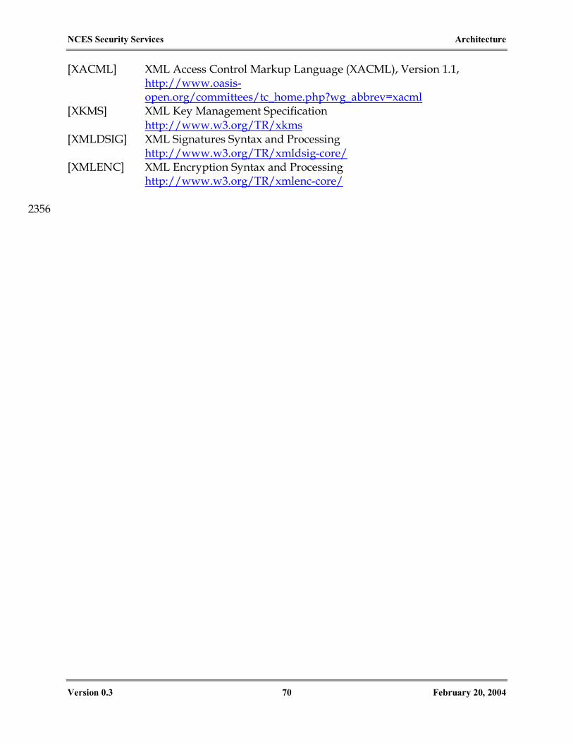
NCES Security Services Architecture
Version 0.3 70 February 20, 2004
[XACML] XML Access Control Markup Language (XACML), Version 1.1, http://www.oasis-open.org/committees/tc_home.php?wg_abbrev=xacml
[XKMS] XML Key Management Specification http://www.w3.org/TR/xkms
[XMLDSIG] XML Signatures Syntax and Processing http://www.w3.org/TR/xmldsig-core/
[XMLENC] XML Encryption Syntax and Processing http://www.w3.org/TR/xmlenc-core/
2356


![PA160: Net-Centric Computing II. [10pt]Network Security](https://static.fdocuments.net/doc/165x107/622f4f91c8b39e020058a784/pa160-net-centric-computing-ii-10ptnetwork-security.jpg)