A Scanning Vibrating Electrode Study of Chromated-Epoxy … scanning vibrating electrode study...
6
Journal of The Electrochemical Society, 147 (10) 3661-3666 (2000) 3661 S0013-4651(00)01-028-4 CCC: $7.00 © The Electrochemical Society, Inc. Historically, coatings designed to protect structural metals such as steel and aluminum from corrosion have incorporated slightly soluble lead and chromate-based pigments, such as zinc chromate, zinc tetroxy chromate, strontium chromate, and basic lead silicochro- mate. 1 For example, the United States Air Force uses chromate-rich primers for corrosion control on most of its aircraft, which typically are made of aluminum 2024-T3 alloy. 2 These primers are typically used in combination with a surface pretreatment employing Alo- dine™, a solution containing chromate and other components such as sodium fluoborate, potassium ferricyanide, and potassium fluozir- conate. Although these chromate-based systems are highly effective for corrosion protection, their use will soon become sharply curtailed due to new government regulations concerning both protection of the environment and protection of industrial workers. 1,3 Thus, an inten- sive effort is underway to develop suitable replacements for chro- mate-based coatings. 4 This effort is hampered by lack of a detailed understanding of how the chromate-based coatings function. 4 In this work, the scanning vibrating electrode technique (SVET), 5,6 also known as the current density probe (CDP), was used to measure current flowing at chromated-epoxy coated steel and alu- minum substrates. The coatings were scribed to simulate a defect through the coating to the metal substrate surface. A plain (nonchro- mated) epoxy coating was also studied for comparison. The SVET was used to map the current flowing in and around the defect while the sample was immersed in either 3% NaCl (steel) or in dilute Har- rison solution (aluminum). The aim of this work was twofold. First, the use of the SVET to study chromated-epoxy primers does not appear to have been report- ed previously. Thus, it was anticipated that these experiments would provide additional insight into the mechanism of protection of struc- tural metals by such primers. Second, in a companion paper we report the results of SVET measurements on a conducting polymer coating, poly(3-octyl pyrrole), on steel and aluminum. 7 The results described here for the chromated-epoxy primer provide a foundation for discussing the similarities and differences in behavior of the con- ducting polymer system. Experimental Sample preparation and experimental conditions.—The plain epoxy coating was a polymer of epichlorohydrin and bisphenol A (Dow Chemical D.E.R. 331) with Ancamide 2353 curing agent (Air Products). The chromated-epoxy coating was a high solids primer coating (Mil-P-23377G, DEFT, Inc.). Cold-rolled steel (Q-Panel) or aluminum alloy (Al 2024-T3, Q-Panel) samples were first polished using 600 grit silicon carbide, washed with hexane, and air-dried. After this pretreatment, the corresponding coatings were applied by bar coating and were allowed to dry overnight. The average coating thickness for the plain epoxy was 30 6 8.5 mm, for the chromated- epoxy 21 6 4.5 mm. The coating of each sample contained a defect that was introduced by scribing, the area of the defect ranging from 0.1 to 0.3 mm 2 . No conversion coatings and no topcoats were used in this study. For the Al 2024-T3 samples, the immersion solution was dilute Harrison solution, containing 0.35% (NH 4 ) 2 SO 4 and 0.05% NaCl in H 2 O. For the cold-rolled steel samples, the immersion solution was 3% NaCl solution. These solutions were prepared from reagent grade salts and distilled water. Instrumentation.—SVET permits the mapping of current density in an electrolyte immediately above a substrate surface. The instru- ment used in this study was from Applicable Electronics (Forestdale, MA). A microelectrode, an electrochemically etched Pt/Ir (80%/20%) wire coated with parylene and arced at the tip to expose the metal, is platinized to form a small ball of platinum black at the tip, approximately 20 mm in diameter in this study. This electrode or probe is vibrated in two dimensions (parallel and perpendicular to the surface, approximately one tip diameter in each dimension) as the tip is rastered above the surface of the substrate at a height of ca. 100 mm. Current flow in the electrolyte due (for example) to corro- sion processes occurring on the substrate surface results in a voltage (IR) drop within the electrolyte. This voltage drop is sensed by the vibrating probe and resolved by two phase-sensitive detectors into a voltage vector having magnitude and direction. The voltage vector is converted into a current density vector using calibration data gener- ated in a separate experiment (calibration involves generation of a known current density from a point source calibration electrode). The measured current density vectors permit mapping of both the magnitude and direction of current flow immediately above the sub- strate surface. This current density map can be overlaid onto an opti- cal micrograph of the substrate captured by a video microscope. This capability permits correlation of anodic and cathodic current pro- cesses with visual features on the substrate surface. The SVET is capable of providing detailed spatially resolved information not readily obtainable by other techniques. A Scanning Vibrating Electrode Study of Chromated-Epoxy Primer on Steel and Aluminum Jie He, a Victoria Johnston Gelling, a Dennis E. Tallman, a, * ,z and Gordon P. Bierwagen b, * a Department of Chemistry and b Department of Polymers and Coatings, North Dakota State University, Fargo, North Dakota 58105, USA Chromated-epoxy primers are often used for corrosion control of iron and aluminum structural alloys. However, due to environ- mental concerns and adverse health effects surrounding such use of chromates, there is an intensive effort to find suitable replace- ments for chromate-based coatings. This effort is hampered by lack of a detailed understanding of how the chromate-based coat- ings function. In this work, the scanning vibrating electrode technique (SVET), also known as the current density probe, was used to measure current flowing at chromated-epoxy coated steel and aluminum substrates. The coatings were scribed to simulate a defect through the coating to the metal substrate surface. A plain (nonchromated) epoxy coating was also studied for comparison. The SVET was used to map the current flowing in and around the defect while the sample was immersed in either 3% NaCl (steel) or in dilute Harrison solution (aluminum). Both steel and aluminum substrates coated with the chromated epoxy exhibited a sig- nificant delay before the onset of corrosion within the scribe, compared with substrates coated with nonchromated epoxy. Fur- thermore, the current density maps for steel suggest that the reduction reaction may occur at the surface of the chromated-epoxy coating. With the nonchromated-epoxy coating, the reduction reaction was always confined to the defect area. © 2000 The Electrochemical Society. S0013-4651(00)01-028-4. All rights reserved. Manuscript submitted January 10, 2000; revised manuscript received June 19, 2000. * Electrochemical Society Active Member. z E-mail: [email protected]
Transcript of A Scanning Vibrating Electrode Study of Chromated-Epoxy … scanning vibrating electrode study...

Journal of The Electrochemical Society, 147 (10) 3661-3666 (2000) 3661S0013-4651(00)01-028-4 CCC: $7.00 © The Electrochemical Society, Inc.
A Scanning Vibrating Electrode Study of Chromated-Epoxy Primer onSteel and Aluminum
Jie He,a Victoria Johnston Gelling,a Dennis E. Tallman,a,*,z and Gordon P. Bierwagenb,*aDepartment of Chemistry and bDepartment of Polymers and Coatings, North Dakota State University, Fargo,North Dakota 58105, USA
Chromated-epoxy primers are often used for corrosion control of iron and aluminum structural alloys. However, due to environ-mental concerns and adverse health effects surrounding such use of chromates, there is an intensive effort to find suitable replace-ments for chromate-based coatings. This effort is hampered by lack of a detailed understanding of how the chromate-based coat-ings function. In this work, the scanning vibrating electrode technique (SVET), also known as the current density probe, was usedto measure current flowing at chromated-epoxy coated steel and aluminum substrates. The coatings were scribed to simulate adefect through the coating to the metal substrate surface. A plain (nonchromated) epoxy coating was also studied for comparison.The SVET was used to map the current flowing in and around the defect while the sample was immersed in either 3% NaCl (steel)or in dilute Harrison solution (aluminum). Both steel and aluminum substrates coated with the chromated epoxy exhibited a sig-nificant delay before the onset of corrosion within the scribe, compared with substrates coated with nonchromated epoxy. Fur-thermore, the current density maps for steel suggest that the reduction reaction may occur at the surface of the chromated-epoxycoating. With the nonchromated-epoxy coating, the reduction reaction was always confined to the defect area.© 2000 The Electrochemical Society. S0013-4651(00)01-028-4. All rights reserved.
Manuscript submitted January 10, 2000; revised manuscript received June 19, 2000.
Historically, coatings designed to protect structural metals such assteel and aluminum from corrosion have incorporated slightly solublelead and chromate-based pigments, such as zinc chromate, zinctetroxy chromate, strontium chromate, and basic lead silicochro-mate.1 For example, the United States Air Force uses chromate-richprimers for corrosion control on most of its aircraft, which typicallyare made of aluminum 2024-T3 alloy.2 These primers are typicallyused in combination with a surface pretreatment employing Alo-dine™, a solution containing chromate and other components such assodium fluoborate, potassium ferricyanide, and potassium fluozir-conate. Although these chromate-based systems are highly effectivefor corrosion protection, their use will soon become sharply curtaileddue to new government regulations concerning both protection of theenvironment and protection of industrial workers.1,3 Thus, an inten-sive effort is underway to develop suitable replacements for chro-mate-based coatings.4 This effort is hampered by lack of a detailedunderstanding of how the chromate-based coatings function.4
In this work, the scanning vibrating electrode technique(SVET),5,6 also known as the current density probe (CDP), was usedto measure current flowing at chromated-epoxy coated steel and alu-minum substrates. The coatings were scribed to simulate a defectthrough the coating to the metal substrate surface. A plain (nonchro-mated) epoxy coating was also studied for comparison. The SVETwas used to map the current flowing in and around the defect whilethe sample was immersed in either 3% NaCl (steel) or in dilute Har-rison solution (aluminum).
The aim of this work was twofold. First, the use of the SVET tostudy chromated-epoxy primers does not appear to have been report-ed previously. Thus, it was anticipated that these experiments wouldprovide additional insight into the mechanism of protection of struc-tural metals by such primers. Second, in a companion paper wereport the results of SVET measurements on a conducting polymercoating, poly(3-octyl pyrrole), on steel and aluminum.7 The resultsdescribed here for the chromated-epoxy primer provide a foundationfor discussing the similarities and differences in behavior of the con-ducting polymer system.
ExperimentalSample preparation and experimental conditions.—The plain
epoxy coating was a polymer of epichlorohydrin and bisphenol A(Dow Chemical D.E.R. 331) with Ancamide 2353 curing agent (Air
* Electrochemical Society Active Member.z E-mail: [email protected]
Products). The chromated-epoxy coating was a high solids primercoating (Mil-P-23377G, DEFT, Inc.). Cold-rolled steel (Q-Panel) oraluminum alloy (Al 2024-T3, Q-Panel) samples were first polishedusing 600 grit silicon carbide, washed with hexane, and air-dried.After this pretreatment, the corresponding coatings were applied bybar coating and were allowed to dry overnight. The average coatingthickness for the plain epoxy was 30 6 8.5 mm, for the chromated-epoxy 21 6 4.5 mm. The coating of each sample contained a defectthat was introduced by scribing, the area of the defect ranging from0.1 to 0.3 mm2. No conversion coatings and no topcoats were usedin this study.
For the Al 2024-T3 samples, the immersion solution was diluteHarrison solution, containing 0.35% (NH4)2SO4 and 0.05% NaCl inH2O. For the cold-rolled steel samples, the immersion solution was3% NaCl solution. These solutions were prepared from reagentgrade salts and distilled water.
Instrumentation.—SVET permits the mapping of current densityin an electrolyte immediately above a substrate surface. The instru-ment used in this study was from Applicable Electronics (Forestdale,MA). A microelectrode, an electrochemically etched Pt/Ir(80%/20%) wire coated with parylene and arced at the tip to exposethe metal, is platinized to form a small ball of platinum black at thetip, approximately 20 mm in diameter in this study. This electrode orprobe is vibrated in two dimensions (parallel and perpendicular tothe surface, approximately one tip diameter in each dimension) asthe tip is rastered above the surface of the substrate at a height of ca.100 mm. Current flow in the electrolyte due (for example) to corro-sion processes occurring on the substrate surface results in a voltage(IR) drop within the electrolyte. This voltage drop is sensed by thevibrating probe and resolved by two phase-sensitive detectors into avoltage vector having magnitude and direction. The voltage vector isconverted into a current density vector using calibration data gener-ated in a separate experiment (calibration involves generation of aknown current density from a point source calibration electrode).The measured current density vectors permit mapping of both themagnitude and direction of current flow immediately above the sub-strate surface. This current density map can be overlaid onto an opti-cal micrograph of the substrate captured by a video microscope. Thiscapability permits correlation of anodic and cathodic current pro-cesses with visual features on the substrate surface. The SVET iscapable of providing detailed spatially resolved information notreadily obtainable by other techniques.

3662 Journal of The Electrochemical Society, 147 (10) 3661-3666 (2000)S0013-4651(00)01-028-4 CCC: $7.00 © The Electrochemical Society, Inc.
Samples for SVET measurement were cut into 1 3 1 cm squaresand were masked by a Polyester 5 adhesive tape (3M Company) suchthat only a 2 3 2 mm square opening of the sample was exposed. Theartificial defect was made using a scribing tool, the sample wasmounted in a Teflon sample cell, and ca. 5 mL of the appropriateimmersion solution was added. Scans were initiated within 5 min ofimmersion and were collected every 20 min for the duration of theexperiment, typically 20 h. Each scan consisted of 400 data pointsobtained on a 20 3 20 grid, with an integration time of 1 s per point.A complete scan required 10 min, followed by a 10 min rest periodprior to the next scan. The current density maps of this paper are dis-played in two ways. In one method, the normal or z-component of themeasured current density in the plane of the vibrating electrode isplotted in 3D format over the scan area, with positive and negativecurrent densities representing anodic and cathodic regions, respec-tively. In the other method, vectors representing current density mag-nitude and direction are superimposed onto an optical image of theimmersed sample. In all cases, the bottom edge of the optical micro-graph corresponds to the x axis of the 3D plot.
The measurements were taken at the open-circuit potential. Atleast six specimens of each sample type were prepared and scannedto assess reproducibility of the observed phenomena. In each case,representative scans are presented. The background noise in ourSVET instrumentation was estimated to be 3 mA/cm2, determinedfrom the standard deviation of the variations in current density atsufficiently large distance (ca. 1 mm) from the point source calibra-tion electrode passing 60 nA of current.
Results and DiscussionThe mapping of current density.—The electrochemical tech-
niques commonly used in corrosion studies (for example, linearpolarization, electrochemical impedance spectroscopy, or electro-chemical noise methods) provide data that reflect an average re-sponse over the entire sample surface. While such data is very use-ful, no local or spatial information is obtained. A number of tech-niques have been developed recently which permit mapping of localcurrent flows in the electrolyte above an immersed substrate, pro-viding a more detailed view of corrosion processes. Typically, thesetechniques map the local potential field that arises due to currentflow through the resistive electrolyte and the potential map is thenconverted to a current density map by a calibration process.
The scanning reference electrode technique (SRET) as originallyimplemented maps the potential by scanning two microreferenceelectrodes near the surface of the substrate under immersion.8 Morerecent versions of the SRET use a single vibrating microelectrode,leading to improvements in spatial resolution.9 This technique isoften referred to as SVET, although there are several variations inhow the electrode is actually vibrated.9 These techniques are limitedto measuring dc currents which restricts their application to the studyof bare metal substrates or coated metals having coating defects. 10,11
Local electrochemical impedance spectroscopy (LEIS) uses atwin microelectrode probe to measure the ac current flowing near thesurface of a substrate that results from an ac potential perturbationapplied to the substrate.12 Thus, LEIS is applicable to both bare andcoated metals under immersion,13,14 but the requirement of a twinmicroelectrode probe sacrifices some spatial resolution. Recent vari-ations of the SVET permit local impedance measurements using thesingle vibrating electrode.15,16
Control experiments.—In this work, the current density in andaround a defect in a chromated-epoxy coating applied either to cold-rolled steel (and immersed in 3% NaCl) or to aluminum 2024-T3(and immersed in dilute Harrison solution) was studied using theSVET. Control experiments involving bare cold-rolled steel and bareAl 2024-T3 in the corresponding immersion solutions were alsoconducted. In every case, these bare metals exhibited one or more (inthe case of the Al alloy, typically several) regions of anodic activity,reflecting sites of localized corrosion, with current densities of 100-200 mA/cm2. With steel, the corrosion often continued until thebuildup of corrosion products at a particular site led to a crash of the
scanning probe. With Al 2024-T3, the activity was much moredynamic, with anodic sites appearing (onset of pitting corrosion) andthen disappearing (passivation) on a time scale of tens of minutes. Ofimportance to the following discussion is the observation that corro-sion onset at these bare metal samples was virtually immediate, withthe observation of significant current flow during the first SVETscan, which was initiated within 5 min of immersion.
As an additional control experiment, current density maps wereobtained for steel and Al alloy samples coated with a plain (nonchro-mated) epoxy primer. A defect was introduced by scribing throughthe coating to the bare metal surface. The results of these experi-ments are exemplified by the result for steel shown in Fig. 1. Clear-ly visible in the micrograph of Fig. 1 is the 2 3 2 mm scan areadefined by the Polyester 5 adhesive tape. The defect, which is paral-lel to the x axis, is visible within this scan area. From Fig. 1, it isclear that the major current flow is from a single anodic site to a sin-gle cathodic site, each located within the defect. This confirms thatthe coating is effectively removed by scribing, exposing the baremetal. In every such control experiment for steel and aluminum,similar behavior was observed, with oxidation and reduction cur-rents confined to the defect. With steel, the onset of corrosion with-in the defect was very rapid, typically observed in the first scan (i.e.,within 5 min). With aluminum, the onset of corrosion within thedefect was somewhat more variable but was typically observed bythe second scan (i.e., within 20 min). For the steel sample of Fig. 1,the current slowly diminished toward zero over the course of approx-imately 3.5 h, at which point the leftmost two-thirds of the defect
Figure 1. Current density maps for the plain epoxy primer on steel at 5 minimmersion in 3% NaCl: (top) 3D representation of the z component of thecurrent density and (bottom) optical micrograph of the sample with currentdensity vectors superimposed.

Journal of The Electrochemical Society, 147 (10) 3661-3666 (2000) 3663S0013-4651(00)01-028-4 CCC: $7.00 © The Electrochemical Society, Inc.
area was covered with corrosion product (Fig. 2). The cathodic siteremained free of corrosion product throughout the experiment.
We note that Kinlen and co-workers recently conducted a similarSRET experiment at epoxy-coated carbon steel with a 1 mm diampinhole drilled through the coating to the metal surface. They alsoobserved anodic and cathodic reactions occurring within the defect.The onset of corrosion was immediate and the corrosion rate did notappear to diminish over the 8 h duration of the experiment.
Chromated-epoxy primer on steel.—Two differences wereobserved in the experiments involving chromated-epoxy primer onsteel. First, whereas large currents were observed within 5 min in thecontrol experiments, there was a significant delay of 40 min orlonger before the onset of any observable corrosion current in theseexperiments. Second, significant reduction current on the exposedmetal in the defect, as always observed in the control experiments,was not observed in these experiments.
Figure 3 shows a sample after 169 min of immersion (the firstobservable current for this particular sample was at 42 min immer-sion). Oxidation was clearly occurring within the defect and corrosionproduct is visible at the anodic site in the optical micrograph. How-ever, little if any reduction occurred within the defect. Rather, reduc-tion appeared to occur more or less uniformly across the coating sur-face. Since the reduction current was spread over a relatively largearea, the current density at any one point was rather small, similar inmagnitude to the noise level. Therefore, we repeated this experimenteight times to confirm this general behavior. In every case the surfaceof the coating was uniformly depressed below zero current (i.e., uni-
Figure 2. Current density maps for the plain epoxy primer on steel at 192min immersion in 3% NaCl: (top) 3D representation of the z component ofthe current density and (bottom) optical micrograph of the sample (currentdensity vectors omitted for clarity). Corrosion product is visible over muchof the defect area.
formly cathodic), with little or no reduction current within the defect.With the plain epoxy control experiments, the total anodic current andtotal cathodic current flowing above the defect were approximatelyequal. In these chromated-epoxy experiments, the anodic current wasalways greater. We conclude that reduction in these experiments didindeed occur over the chromated-epoxy coating.
There are two reduction mechanisms that might explain these ob-servations. In one mechanism, the reduction reaction could occur atthe coating-electrolyte interface, with electron transfer to the under-lying metal mediated by the chromate pigment in the epoxy coating.In the other mechanism, the reduction reaction could occur at themetal-coating interface, the result of diffusion of the oxidant throughthe coating to the metal surface. Both mechanisms would give rise toa cathodic current flow above the coating surface.
We favor the first mechanism for the following reasons. First, thereduction current always appeared to be rather uniformly distributedacross the coating surface. Reduction at the metal-coating interfacewould likely be more localized, with transport (e.g., of oxygen) tothe metal interface occurring primarily through coating defects. Sec-ond, the first occurrence of observable oxidation within the defect atca. 40 min is accompanied by uniform reduction over the coatingsurface, a time we consider too short for uniform penetration ofwater and oxidants through the coating to the metal interface.18 It isnoted, however, that the pigment volume concentration of this high-
Figure 3. Current density maps for chromated-epoxy primer on steel at169 min immersion in 3% NaCl: (top) 3D representation of the z componentof the current density and (bottom) optical micrograph of the sample withcurrent density vectors superimposed.

3664 Journal of The Electrochemical Society, 147 (10) 3661-3666 (2000)S0013-4651(00)01-028-4 CCC: $7.00 © The Electrochemical Society, Inc.
ly pigmented primer (ca. 40-45%)19 is close to the critical pigmentvolume concentration (ca. 50%), and pathways of conductivity dueto electrolyte channels may form in the partial porosity that occursin such coatings.20 Finally, if the mechanism involves simple diffu-sion through the coating and reduction at the underlying metal, thensimilar behavior might be expected for an aluminum alloy. Howev-er, at aluminum alloy the reduction occurs preferentially within thedefect (see the following section). This suggests a more metal-spe-cific mechanism, such as might occur if coupling of electron trans-fer between metal and coating were involved.
If reduction is occurring at the coating-electrolyte interface, theimplications are twofold. First, the chromated-epoxy coating mustbe capable of shuttling electrons from the metal to an oxidant insolution. That is, the coating would need to be electronically con-ducting or semiconducting. The mechanism of conduction in thiscoating is unclear but could involve electron transfer between con-tacting chromate particles within the coating, similar to that occur-ring in redox polymers such as poly(vinylferrocene).21 Experimentsare underway to assess the conductivity of the chromated-epoxycoating. Second, cathodic delamination of a coating is generallyassociated with a high local hydroxide concentration generated bythe reduction reaction occurring at the coating-metal interface.22,23
Removal of the reduction reaction from the metal interface may bean important aspect of the mechanism by which chromated coatingsextend the lifetime of the complete coating system. A mechanism ofthis type has been proposed for conducting polymers24 and, indeed,reduction reactions at poly(3-octyl pyrrole) coatings7 and at polyani-line coatings17 on steel have been observed.
In these experiments, we observed no tendency for the chromat-ed-epoxy primer to rapidly passivate the steel. In fact, once corrosioncurrent began to flow (following the initial delay), it continued for18 to 20 h, until corrosion products eventually covered the anodicsite and diminished the current to near background levels. In con-trast, the current at plain epoxy coated steel diminished after only 3-4 h (Fig. 2). This suggests that the presence of the oxidant (chro-mate) in the epoxy primer actually sustains the current under ourimmersion conditions. Very similar behavior was observed for apolypyrrole coating (also an oxidant) on steel.7 An additional obser-vation may be relevant here. The corrosion products formed at thedefect of the plain epoxy-coated steel appeared to be more volumi-nous and less adherent, with considerable suspended matter formingin the immersion solution during the course of the experiment. Theproducts formed at the defect of the chromated-epoxy coated steelappeared to be much more adherent, with little or no suspendedmaterial appearing in the immersion solution in spite of the consid-erably greater time over which oxidation occurred.
An insulating topcoat such as polyurethane would be expected toblock the reduction reaction observed at the chromated-epoxy coat-ing surface, forcing the reduction process to occur at the defect. Inpreliminary experiments with chromated-epoxy samples prepared asdescribed previously but with a ca. 50 mm thick polyurethane top-coat and a defect introduced through both coatings to the metal sur-face, the oxidation and reduction reactions were indeed confined tothe defect. Importantly, there was still a delay of approximately 1 hbefore observation of any redox activity, a delay similar to thatobserved without the topcoat. Further studies of topcoated substratesare in progress.
Chromated-epoxy primer on Al 2024-T3.—The chromated-epoxy primer on Al 2024-T3 alloy, as on steel, significantly retard-ed the onset of corrosion. Whereas corrosion activity was observedwithin ca. 20 min for the plain epoxy control samples, the firstdetectable current with the chromated-epoxy samples was typicallyafter 5 h of immersion. The results are exemplified by Fig. 4, whichshows the current density maps for a particular sample after 5 minimmersion and after 5.5 h immersion. The 5 min map is typical ofthose obtained over the first 5 h of immersion, showing no detectablecorrosion of the metal exposed in the defect. The exposed metal inthe defect remained shiny during this period. The first sign of corro-
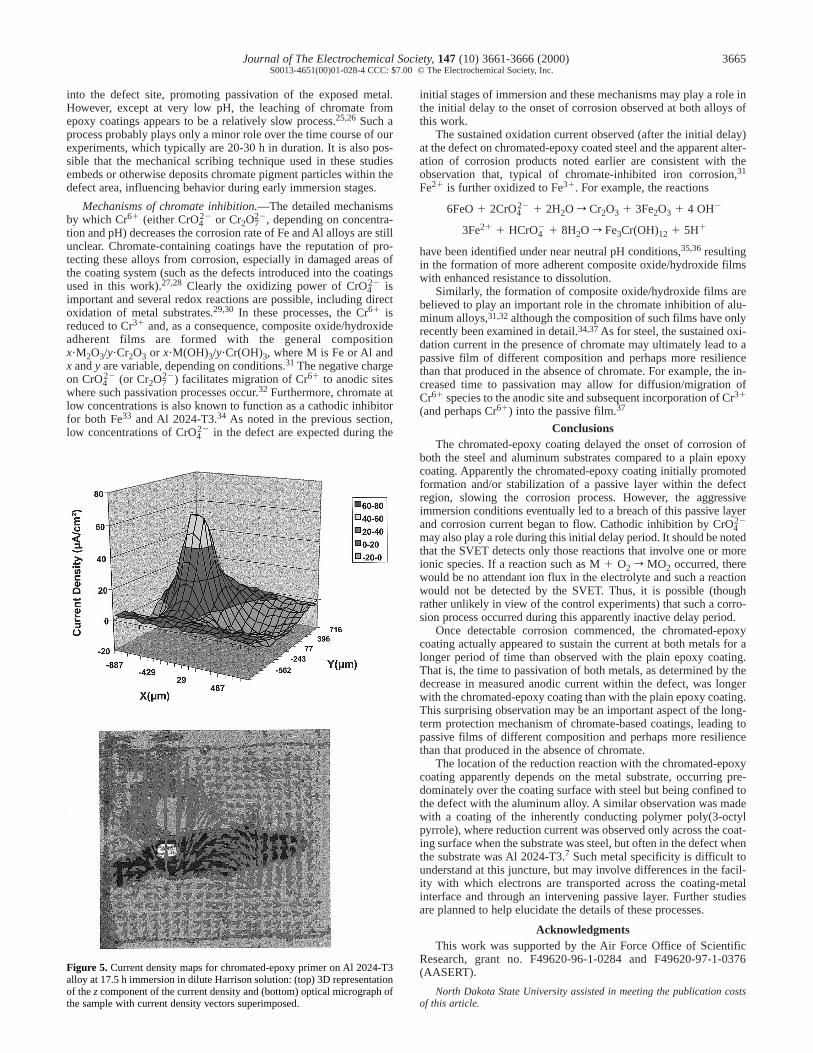
sion is displayed in the 5.5 h map (Fig. 4), with both oxidation andreduction being confined to the defect area. As with the steel sam-ples, this corrosion current continued to increase over the next sev-eral hours of immersion, and most of the exposed metal area in thedefect turned dark. Figure 5 shows the current density maps for thesame sample after 17.5 h immersion, by which time the current hadincreased substantially but still appeared to be confined to the defectarea. Two local cathode sites, one on each side of the anode site, areobserved. As noted in the previous section, this behavior is in con-trast to that on steel where cathodic currents above the coating wereobserved. The site of corrosion is clearly visible in Fig. 5 as the re-maining shiny metal spot in the micrograph.
Long-term immersion experiments were conducted to determinethe time required for the corrosion current to diminish to backgroundlevels. For the plain epoxy control experiment, the average time re-quired was approximately 16 h. For the chromated-epoxy coatedsamples, the average time required was greater than 24 h. As forsteel, the presence of the oxidant chromate appeared to sustain thecorrosion current.
In a related study, the SRET was used to investigate a scratchedchromated-epoxy primer on galvanized steel immersed in an artifi-cial acid rain solution.25 In that work, as in this, the chromate-con-taining epoxy coating delayed the onset of corrosion within thedefect compared to a chromate-free epoxy coating. Once corrosionensued, the chromated-epoxy sample displayed a more rapid passi-vation, requiring 2-3 days under their immersion conditions. It wassuggested that the chromated-epoxy coating released chromate ions
Figure 4. Current density maps for chromated-epoxy primer on Al 2024-T3alloy at (top) 5 min and (bottom) 5.5 h immersion in dilute Harrison solution(3D representation of the z component of the current density). See Fig. 5 forthe optical micrograph of this sample.
Journal of The Electrochemical Society, 147 (10) 3661-3666 (2000) 3665S0013-4651(00)01-028-4 CCC: $7.00 © The Electrochemical Society, Inc.
into the defect site, promoting passivation of the exposed metal.However, except at very low pH, the leaching of chromate fromepoxy coatings appears to be a relatively slow process.25,26 Such aprocess probably plays only a minor role over the time course of ourexperiments, which typically are 20-30 h in duration. It is also pos-sible that the mechanical scribing technique used in these studiesembeds or otherwise deposits chromate pigment particles within thedefect area, influencing behavior during early immersion stages.
Mechanisms of chromate inhibition.—The detailed mechanismsby which Cr61 (either CrO4
22 or Cr2O722, depending on concentra-
tion and pH) decreases the corrosion rate of Fe and Al alloys are stillunclear. Chromate-containing coatings have the reputation of pro-tecting these alloys from corrosion, especially in damaged areas ofthe coating system (such as the defects introduced into the coatingsused in this work).27,28 Clearly the oxidizing power of CrO4
22 isimportant and several redox reactions are possible, including directoxidation of metal substrates.29,30 In these processes, the Cr61 isreduced to Cr31 and, as a consequence, composite oxide/hydroxideadherent films are formed with the general compositionx?M2O3/y?Cr2O3 or x?M(OH)3/y?Cr(OH)3, where M is Fe or Al andx and y are variable, depending on conditions.31 The negative chargeon CrO4
22 (or Cr2O722) facilitates migration of Cr61 to anodic sites
where such passivation processes occur.32 Furthermore, chromate atlow concentrations is also known to function as a cathodic inhibitorfor both Fe33 and Al 2024-T3.34 As noted in the previous section,low concentrations of CrO4
22 in the defect are expected during the
Figure 5. Current density maps for chromated-epoxy primer on Al 2024-T3alloy at 17.5 h immersion in dilute Harrison solution: (top) 3D representationof the z component of the current density and (bottom) optical micrograph ofthe sample with current density vectors superimposed.
initial stages of immersion and these mechanisms may play a role inthe initial delay to the onset of corrosion observed at both alloys ofthis work.
The sustained oxidation current observed (after the initial delay)at the defect on chromated-epoxy coated steel and the apparent alter-ation of corrosion products noted earlier are consistent with theobservation that, typical of chromate-inhibited iron corrosion,31
Fe21 is further oxidized to Fe31. For example, the reactions
6FeO 1 2CrO422 1 2H2O r Cr2O3 1 3Fe2O3 1 4 OH2
3Fe21 1 HCrO42 1 8H2O r Fe3Cr(OH)12 1 5H1
have been identified under near neutral pH conditions,35,36 resultingin the formation of more adherent composite oxide/hydroxide filmswith enhanced resistance to dissolution.
Similarly, the formation of composite oxide/hydroxide films arebelieved to play an important role in the chromate inhibition of alu-minum alloys,31,32 although the composition of such films have onlyrecently been examined in detail.34,37 As for steel, the sustained oxi-dation current in the presence of chromate may ultimately lead to apassive film of different composition and perhaps more resiliencethan that produced in the absence of chromate. For example, the in-creased time to passivation may allow for diffusion/migration ofCr61 species to the anodic site and subsequent incorporation of Cr31
(and perhaps Cr61) into the passive film.37
ConclusionsThe chromated-epoxy coating delayed the onset of corrosion of
both the steel and aluminum substrates compared to a plain epoxycoating. Apparently the chromated-epoxy coating initially promotedformation and/or stabilization of a passive layer within the defectregion, slowing the corrosion process. However, the aggressiveimmersion conditions eventually led to a breach of this passive layerand corrosion current began to flow. Cathodic inhibition by CrO4
22
may also play a role during this initial delay period. It should be notedthat the SVET detects only those reactions that involve one or moreionic species. If a reaction such as M 1 O2 r MO2 occurred, therewould be no attendant ion flux in the electrolyte and such a reactionwould not be detected by the SVET. Thus, it is possible (thoughrather unlikely in view of the control experiments) that such a corro-sion process occurred during this apparently inactive delay period.
Once detectable corrosion commenced, the chromated-epoxycoating actually appeared to sustain the current at both metals for alonger period of time than observed with the plain epoxy coating.That is, the time to passivation of both metals, as determined by thedecrease in measured anodic current within the defect, was longerwith the chromated-epoxy coating than with the plain epoxy coating.This surprising observation may be an important aspect of the long-term protection mechanism of chromate-based coatings, leading topassive films of different composition and perhaps more resiliencethan that produced in the absence of chromate.
The location of the reduction reaction with the chromated-epoxycoating apparently depends on the metal substrate, occurring pre-dominately over the coating surface with steel but being confined tothe defect with the aluminum alloy. A similar observation was madewith a coating of the inherently conducting polymer poly(3-octylpyrrole), where reduction current was observed only across the coat-ing surface when the substrate was steel, but often in the defect whenthe substrate was Al 2024-T3.7 Such metal specificity is difficult tounderstand at this juncture, but may involve differences in the facil-ity with which electrons are transported across the coating-metalinterface and through an intervening passive layer. Further studiesare planned to help elucidate the details of these processes.
AcknowledgmentsThis work was supported by the Air Force Office of Scientific
Research, grant no. F49620-96-1-0284 and F49620-97-1-0376(AASERT).
North Dakota State University assisted in meeting the publication costsof this article.

3666 Journal of The Electrochemical Society, 147 (10) 3661-3666 (2000)S0013-4651(00)01-028-4 CCC: $7.00 © The Electrochemical Society, Inc.
References1. C. Simpson, Organic Coatings for Corrosion Control, G. P. Bierwagen, Editor,
ACS Symposium Series 689, p. 356 (1998). 2. R. L. Twite, V. Balbyshev, G. P. Bierwagen, and D. E. Tallman, in Environmental-
ly Acceptable Inhibitors and Coatings, S. R. Taylor and H. Issacs, Editors, PV 95-16, p. 202, The Electrochemical Society Proceedings Series, Pennington, NJ(1995).
3. EPA Federal Register, National Emission Standards for Hazardous Air Pollutantsfor Source Categories: Aerospace Manufacturing and Rework Facilities, 60(170),p. 45947, Sept 1, 1995.
4. S. M. Cohen, Corrosion, 51, 71 (1995). 5. C. Scheffey, Rev. Sci. Instrum., 59, 787 (1988). 6. H. S. Isaacs, A. J. Davenport, and A. Shipley, J. Electrochem. Soc., 138, 390 (1991).7. J. He, V. Johnston Gelling, D. E. Tallman, G. P. Bierwagen, and G. G. Wallace,
J. Electrochem. Soc., 147, 3667 (1999).8. H. S. Isaacs and B. Vyas, in Electrochemical Corrosion Testing, ASTM STP-727,
F. Mansfield and U. Bertocci, Editors, pp. 3-31, American Society for Testing andMaterials, Philidelphia, PA (1981).
9. D. A. Sargeant, Corros. Prevent. Control, 44, 91 (1997).10. I. Sekine, M. Yuasa, K. Tanaka, T. Tsutsumi, F. Koizumi, N. Oda, H. Tanabe, and
M. Nagai, Shikizai, 67, 424 (1994).11. I. Sekine, Prog. Org. Coat., 31, 73 (1997). 12. R. S. Lillard, P. J. Moran, and H. S. Isaacs, J. Electrochem. Soc., 139, 1007 (1992).13. M. W. Wittmann and S. R. Taylor, in Advances in Corrosion Protection by Organ-
ic Coatings II, D. Scantlebury and M. Kendig, Editors, PV 95-13, p. 158, The Elec-trochemical Society Proceedings Series, Pennington, NJ (1995).
14. R. B. Leggat and S. R. Taylor, Corrosion, 55, 984 (1999). 15. E. Bayet, F. Huet, M. Keddam, K. Ogle, and H. Takenouti, J. Electrochem. Soc.,
144, L87 (1997). 16. E. Bayet, F. Huet, and H. Takenouti, Electrochim. Acta, 44, 4177 (1999).
17. P. J. Kinlen, V. Menon, and Y. Ding, J. Electrochem. Soc., 146, 3690 (1999).18. H. N. Rosen and J. W. Martin, J. Coat. Tech., 63, 85 (1991).19. C. R. Hegedus, D. F. Pulley, S. J. Spadafora, A. T. Eng, and D. J. Hirst, J. Coat.
Technol., 61, 31 (1989).20. R. S. Fishman, D. A. Kurtz, and G. P. Bierwagen, Prog. Org. Coat., 21, 387 (1993). 21. W. H. Smyrl and M. Lien, Applications of Electroactive Polymers, B. Scrosati, Edi-
tor, p. 29, Chapman and Hall, New York (1993).22. D. A. Jones, Principles and Prevention of Corrosion, 2nd ed., p. 490, Prentice Hall,
Upper Saddle River, NJ (1996). 23. Z. W. Wicks, Jr., F. N. Jones, and S. P. Pappas, Organic Coatings: Science and
Technology, 2nd ed., pp. 131-133, Wiley-Interscience, New York (1999).24. P. J. Kinlen, D. C. Silverman, and C. R. Jeffreys, Synth. Met., 85, 1327 (1997).25. I. M. Zin, R. L. Howard, S. J. Badger, J. D. Scantlebury, and S. B. Lyon, Prog. Org.
Coat., 33, 203 (1998).26. K. C. Tsai and C. H. Tsai, in Proceedings of the 4th Asian-Pacific Conference,
Materials Conservation and Corrosion Control, Vol. 1, p. 491, Tokyo, May 26-31,1985.
27. H. Wienand and W. Ostertag, Modern Paint Coat., 38 (Nov 1984).28. G. Adrian and A. Bittner, J. Coat. Technol., 58, 59 (1986).29. J. R. Waldrop and M. W. Kendig, J. Electrochem. Soc., 145, 1 (1998).30. Z. Szklarska-Smialowska and R. W. Staehle, J. Electrochem. Soc., 121, 1146 (1974).31. J. Sinko, Prog. Org. Coat., In press (2000). 32. M. W. Kendig, A. J. Davenport, and H. S. Issacs, Corros. Sci., 34, 41 (1993).33. G. B. Hatch, Influence of Inhibitors on Differential Aeration Attack on Steel, II-
Dichromate and Orthophosphate, NACE National Conference, NACE, Houston,TX (1964).
34. J. Zhao, G. Frankel and R. McCreery, J. Electrochem. Soc., 145, 2258 (1998). 35. B. P. Boffardi, in Reviews on Corrosion Inhibitor Science and Technology, A.
Raman and P. Labine, Editors, NACE, Houston, TX (1993).36. I. J. Buerge and S. J. Hug, Environ. Sci. Technol., 31, 5 (1997).37. L. Xia and R. L. McCreery, J. Electrochem. Soc., 145, 3083 (1998).