A Safe and Economical Design of Composite Profile Steel ...
13
This document is downloaded from DR‑NTU (https://dr.ntu.edu.sg) Nanyang Technological University, Singapore. A Safe and Economical Design of Composite Profile Steel Decking Systems under Fire Conditions Nguyen, Tuan‑Trung; Tan, Kang‑Hai 2014 Nguyen, T.‑T., & Tan, K.‑H. (2014). A Safe and Economical Design of Composite Profile Steel Decking Systems under Fire Conditions. 2014 Fire Safety Asia Conference Singapore (FiSAC 2014). https://hdl.handle.net/10356/83967 © 2014 Fire Safety Asia Conference Singapore (FiSAC 2014). This is the author created version of a work that has been peer reviewed and accepted for publication by 2014 Fire Safety Asia Conference Singapore (FiSAC 2014), 2014 Fire Safety Asia Conference Singapore (FiSAC 2014). It incorporates referee’s comments but changes resulting from the publishing process, such as copyediting, structural formatting, may not be reflected in this document. The published version is available at: [http://www.fisac.com.sg/]. Downloaded on 18 Dec 2021 01:15:31 SGT
Transcript of A Safe and Economical Design of Composite Profile Steel ...
This document is downloaded from DR‑NTU (https://dr.ntu.edu.sg)Nanyang Technological University, Singapore.
A Safe and Economical Design of CompositeProfile Steel Decking Systems under FireConditions
Nguyen, Tuan‑Trung; Tan, Kang‑Hai
2014
Nguyen, T.‑T., & Tan, K.‑H. (2014). A Safe and Economical Design of Composite Profile SteelDecking Systems under Fire Conditions. 2014 Fire Safety Asia Conference Singapore (FiSAC2014).
https://hdl.handle.net/10356/83967
© 2014 Fire Safety Asia Conference Singapore (FiSAC 2014). This is the author createdversion of a work that has been peer reviewed and accepted for publication by 2014 FireSafety Asia Conference Singapore (FiSAC 2014), 2014 Fire Safety Asia Conference Singapore(FiSAC 2014). It incorporates referee’s comments but changes resulting from thepublishing process, such as copyediting, structural formatting, may not be reflected in thisdocument. The published version is available at: [http://www.fisac.com.sg/].
Downloaded on 18 Dec 2021 01:15:31 SGT
1 PhD Candidate, [email protected]. Tel: +65 67904151 2 Professor of Structural Engineering, [email protected]
A Safe and Economical Design of Composite Profile Steel Decking Systems
under Fire Conditions
Tuan-Trung Nguyen1, Kang-Hai Tan2
School of Civil and Environmental Engineering, Nanyang Technological Univ., Singapore
Abstract
Due to two fire incidents viz. the Basingstoke and the Broadgate Fires, composite slabs
consisting of steel beams and lightly reinforced concrete slabs with steel decking showed an
inherent load-carrying capacity in fire by mobilizing tensile membrane action at large
displacements. Based on a number of research works on tensile membrane action of
composite floor slabs, a design guide has been released in the UK in 2006, viz. SCI
Publication P288, in which the BRE-Bailey method was adopted. This method allows interior
secondary beams to be unprotected so that fire-protection costs can be reduced without
compromising on structural safety. Many composite steel-framed buildings in the UK have
since benefited from the application of the method, resulting in reduced fire protection costs
for secondary steel beams.
An experimental programme including 8 composite beam-slab floor system specimens
had been tested under fire conditions at Nanyang Technological University from 2010-2012
to investigate the assumptions and the validity of the Bailey-BRE method. It is concluded that
the Bailey-BRE method is conservative and SCI P288 can be applied in Singapore without
compromising safety of steel-framed composite structures providing that detailing of
structural members should be followed closely in the construction phase.
Keywords: Tensile membrane action; Slab-beam systems; Restraint; Composite slabs; Fire
1 Introduction
Large-scale fire tests, as well as well-publicised accidental building fires over the past
two decades, have shown that under fire conditions composite slabs consisting of steel beams
and lightly reinforced concrete slabs with steel decking possess a significant load-bearing
capacity, which can be well above that predicted by the conventional yield-line theory. This
load-carrying mechanism has been defined as tensile membrane action (TMA), which can be
mobilized in the composite slabs at large displacements, irrespective whether the slabs are
restrained horizontally or not.
Bailey and Moore (2000) have developed a new design method for composite slabs
under fire conditions, namely, the Bailey-BRE method. This method allows interior
secondary beams to be unprotected so that the fire-protection costs can be reduced. This
method has been adopted in SCI Publication P288 (Newman et al., 2006) and applied in the
UK practice in the recent years.
SCI Publication P288 sets out the design philosophy for the Bailey-BRE method, while
SCI Publication P390 (Simms and Bake, 2010) provides the information on the use of
TSLAB software v3.0 and an update for some parts of P288. This software has been
developed by SCI to facilitate the application of the Bailey-BRE method. P288 has been
developed based on extensive fire test results, ambient temperature tests and finite element
analyses. P390 has incorporated Eurocode requirements and included verification for the
protected edge beam capacity. Both P288 and P390 must be used together when applying the
Bailey-BRE method to design steel-framed buildings with composite slabs. Many buildings
in the UK have since benefited from the application of the simple design method, resulting in
reduced fire protection costs.
The Bailey-BRE method assumes that vertical supports along the slab panel boundaries
at all times during a fire do not deform and are provided by the protected edge beams with
sufficient rigidity and strength during the fire. However, in reality, the deflection of the edge
beams may be considerable and thus this assumption may be unrealistic. Additionally, all
previous experimental studies focussed on isolated slabs rather than on the behaviour of
connected floor assemblies. The question arises whether the method can be applied for
composite beam-slab systems with deflecting edge beams.
Therefore, a fairly extensive test programme has been conducted in Nanyang
Technological University, Singapore (NTU) from 2009 to 2012 to study the assumptions and
validity of the Bailey-BRE method. This paper first discusses in detail the shortcomings of
the Bailey-BRE method, and then presents the calibration of P288 and P390 against the NTU
fire tests.
2 SCI Publication P288 and P390
2.1 Discussions on the Bailey-BRE method
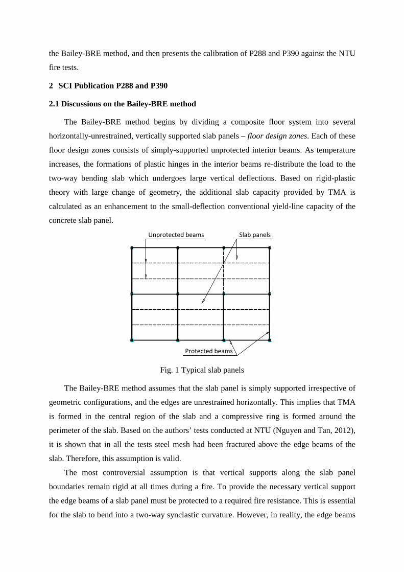
The Bailey-BRE method begins by dividing a composite floor system into several
horizontally-unrestrained, vertically supported slab panels – floor design zones. Each of these
floor design zones consists of simply-supported unprotected interior beams. As temperature
increases, the formations of plastic hinges in the interior beams re-distribute the load to the
two-way bending slab which undergoes large vertical deflections. Based on rigid-plastic
theory with large change of geometry, the additional slab capacity provided by TMA is
calculated as an enhancement to the small-deflection conventional yield-line capacity of the
concrete slab panel.
Fig. 1 Typical slab panels
The Bailey-BRE method assumes that the slab panel is simply supported irrespective of
geometric configurations, and the edges are unrestrained horizontally. This implies that TMA
is formed in the central region of the slab and a compressive ring is formed around the
perimeter of the slab. Based on the authors’ tests conducted at NTU (Nguyen and Tan, 2012),
it is shown that in all the tests steel mesh had been fractured above the edge beams of the
slab. Therefore, this assumption is valid.
The most controversial assumption is that vertical supports along the slab panel
boundaries remain rigid at all times during a fire. To provide the necessary vertical support
the edge beams of a slab panel must be protected to a required fire resistance. This is essential
for the slab to bend into a two-way synclastic curvature. However, in reality, the edge beams
Unprotected beams
Protected beams
Slab panels

may deform considerably even though they are fire-protected, and thus this assumption may
be nullified. This assumption is verified against the authors’ test results and discussed in
Section 4.
When calculating the contribution of unprotected interior beams to the total load-bearing
capacity of the slab, Bailey treated these beams as composite beams. Under tensile membrane
stage, since the load path has been changed from the slab via supporting edge beams to the
columns, if the interior beams are treated as composite beams, the method may overestimate
the total load capacity by taking into account twice the load supported by parts of concrete
slab over the interior beams. The authors have checked this assumption and presented in
Section 4.
In the simple design method a deflection limit has to be assumed, and then the
enhancement above the yield-line capacity of the slab due to TMA can be computed based on
that deflection. This deflection limit is estimated by combining the components due to
thermal curvature and strain in the reinforcement.
( ) ( )o20 C
2 222 1 2 1
maxReinf'
0.5 3 < 19.2 8 19.2 30
α α− − = + = +
y
s a st
fT T l T T lL lw wh E h
(1)
where α is the coefficient of thermal expansion (12x10-6 for normal weight concrete; 2T and
1T are the bottom and top surface temperatures of the slab, respectively; sh is the slab
thickness; l and L are the shorter and longer spans of the slab panel; yf and aE are the yield
strength and the elastic modulus of the reinforcing steel at ambient temperature.
Based on the Cardington fire test, Bailey assumed that ( )2 1T T− is equal to 770oC for
fire exposure below 90 minutes and 900oC thereafter. This value was obtained from the test
data from the Cardington fire tests (Bailey et al., 1999) and referred hereafter as the P288
deflection limit.
In P390 (Simms and Bake, 2010), an updated version of P288, the deflection limit is also
calculated by Eq. (1), except that the term ( )2 1T T− is based on the temperatures calculated at
the bottom and top surfaces of the slab at each time step (referred hereafter as the P390
deflection limit). The difference between the two deflection limits highlights the effect of
recent changes to the Bailey-BRE method (Bailey and Toh, 2007).
The two deflection limits, i.e. P288 and P390 deflection limits, are compared with the
actual test results at ultimate limit state to see if they are conservative.
2.2 Type of structure
It is important to note that SCI P288 and P390 shall not be used to replace SS EN 1994-
1-1:2004 and SS EN 1994-1-2:2005. They only provide design guidance on an advanced
calculation method in design of composite steel-framed buildings to reduce fire-protection
costs.
The two documents SCI P288 and P390 do not apply to:
(1) Floors constructed using precast concrete slabs;
(2) Internal floor beams that have been designed to act non-compositely (beams at the
edge of the floor slab may be non-composite);
(3) Beams with service openings, i.e. composite floor with cellular beams;
(4) Flat slab systems;
(5) Composite slabs that require above 2-hr fire resistance
Structural type (1) to (4) was proposed in SCI P288 and P390. Structural type (5) is
based on the authors’ experimental study in NTU.
3 Experimental Programme in Nanyang Technological University
The test programme conducted in NTU from 2010 to 2012 included two series with eight
composite beam-slab floor systems in total, which were tested under fire conditions to study
the development of tensile membrane action (TMA) in the composite beam-slab systems.
Only brief information of the specimens is provided here. Details of the test results and
discussions can be found in Nguyen and Tan (2014).
The specimens were of one-quarter scale due to limitations of laboratory facility and
space. For interior slab panels, the slabs had an outstand of 0.45m around all four edges.
Shrinkage reinforcement mesh with a grid size of 80mm x 80mm and a diameter of 3mm
(giving a reinforcement ratio of 0.16%) was placed at about 38mm below the slab top
surface. The 0.16% reinforcement ratio was close to the minimum value required by EN
1994-1-1 (0.2% for un-propped construction). The mesh was continuous across the whole
slab, with no lapping of mesh. The specimens were cast using ready-mixed concrete, with the
aggregate size ranging from 5 to 10 mm.
The edge and secondary beams were Class 1 sections according to EN 1993-1-1 (2005a).
Fabricated sections were used for the unprotected interior beams, since there was no suitable
Universal Beam section. Full-shear composite action between the slab and the down-stand
beams was achieved by using shear studs of 40mm height and 13mm diameter.
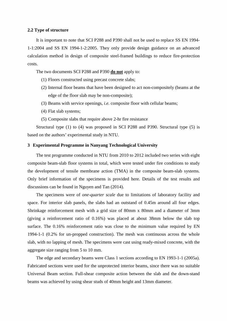
All the edge beams and the columns were protected to one-hour rating. No fire-proofing
material was applied to the interior beams and the slabs.
Table 1 summarises the details of the specimens. Among the eight specimens there were
two without interior beams, namely, S1 and S3-FR. The others had two unprotected interior
beams. Fig. 2 shows the specimens without unprotected interior beams, while Fig. 3 shows
the specimens with two unprotected interior beams.
Table 1 Specimen details
Series L x W x h (mm)
Aspect ratio Main beam
Protected secondary
beam
Unprotected interior beam
S1 2250x2250x55 1.0 W130x130x28.1 80x80x17.3 n.a. I S2-FR-IB 2250x2250x55 1.0 W130x130x28.1 80x80x17.3 80x80x17.3 S3-FR 2250x2250x58 1.0 W130x130x28.1 80x80x17.3 n.a P215-M1099 2250x2250x57 1.0 W130x130x28.1 80x80x17.3 80x80x17.3 P368-M1099 2250x2250x58 1.0 W130x130x28.1 100x80x18.8 80x80x17.3
II P486-M1099 2250x2250x55 1.0 W130x130x28.1 102x102x23 80x80x17.3 P215-M1356 2250x2250x58 1.0 UB 178x102x19 80x80x17.3 80x80x17.3 P215-M2110 2250x2250x59 1.0 UB 203x102x23 100x80x18.8 80x80x17.3
Fig. 2 Specimens without interior beams Fig. 3 Specimens with two unprotected
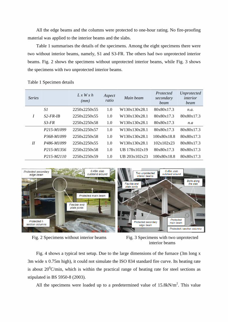
interior beams Fig. 4 shows a typical test setup. Due to the large dimensions of the furnace (3m long x
3m wide x 0.75m high), it could not simulate the ISO 834 standard fire curve. Its heating rate
is about 200C/min, which is within the practical range of heating rate for steel sections as
stipulated in BS 5950-8 (2003).
All the specimens were loaded up to a predetermined value of 15.8kN/m2. This value
corresponded to 0.35 of the yield-line load at ambient temperature for specimens with interior
beams and 2.0 for specimens without interior beams. After that, the load was kept constant
and temperature was increased until failure was identified. This was the time when there was
a significant drop in the mechanical resistance, and the hydraulic jack could no longer
maintain the load level (violation of criterion “R”).
Fig. 4 Test setup
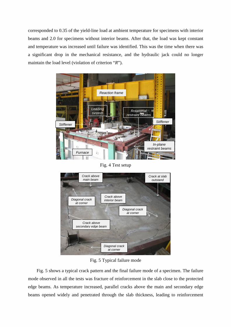
Fig. 5 Typical failure mode
Fig. 5 shows a typical crack pattern and the final failure mode of a specimen. The failure
mode observed in all the tests was fracture of reinforcement in the slab close to the protected
edge beams. As temperature increased, parallel cracks above the main and secondary edge
beams opened widely and penetrated through the slab thickness, leading to reinforcement
Loading system Rotational
restraint beams
In-plane restraint beams
Stiffener Stiffener
Furnace
Reaction frame
Crack above main beam
Crack above secondary edge beam
Diagonal crack at corner
Diagonal crack at corner
Crack at slab outstand
Diagonal crack at corner
Crack above interior beam

fracture. No global collapse occurred. No premature failure at the shear studs and at the
beam-column and beam-beam connections was observed.
4 Calibration of P288 and P390 against NTU fire tests
4.1 Principles
Verification of deflection limits
Fig. 6 shows typical test results of a specimen in which temperatures of the slab (bottom
and top surfaces, and reinforcing mesh) were indicated together with the central deflection of
the slab. Both deflection limits, i.e. P288 and P390 deflection limits, were calculated. The
difference is in the term ( )2 1T T− . For the P288 deflection limit, ( )2 1T T− is equal to 770oC
for fire exposure below 90 minutes and 900oC thereafter. For the P390 deflection limit, 2T
and 1T were determined based on the actual test results at failure. Comparisons between these
two deflection limits and test results are presented in Section 4.2.1.
Fig. 6 Typical test results
Comparisons of load-bearing capacity for specimens without unprotected interior beams
Since the Bailey-BRE method does not consider deflection of edge beams, the
enhancement factor predicted by P288 ( e ) is calculated using the relative slab deflection
measured at failure and compared with the enhancement factor determined from the tests (
teste ). The P288 and P390 deflection limits were not used for these comparisons since all the
specimens failed at a deflection greater than the P288 and P390 deflection limits. Using a
0
100
200
300
400
500
600
700
8000
50
100
150
200
250
0 20 40 60 80 100
Tem
pera
ture
(o C)
Def
lect
ion
(mm
)
Time (min)
Slab top surafce Mesh Slab bottom surface
P288 deflection limit
P390 deflection limit
Deflection at failure
Slab deflection
mw
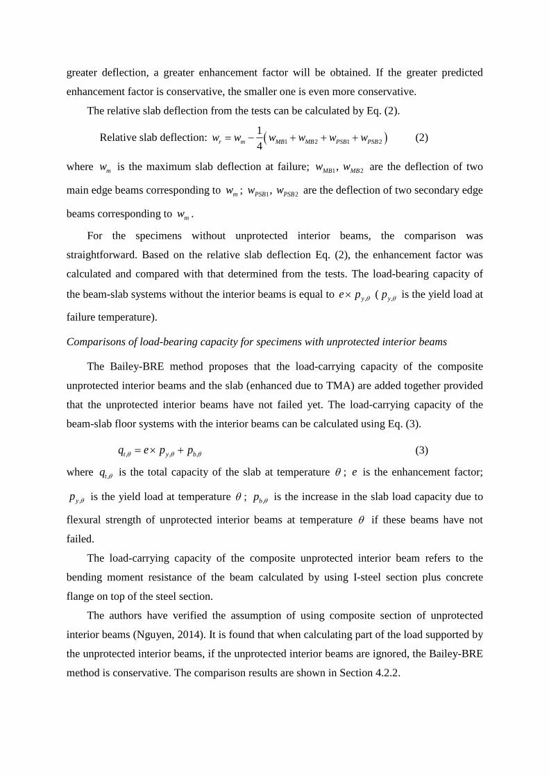
greater deflection, a greater enhancement factor will be obtained. If the greater predicted
enhancement factor is conservative, the smaller one is even more conservative.
The relative slab deflection from the tests can be calculated by Eq. (2).
Relative slab deflection: ( )1 2 1 214r m MB MB PSB PSBw w w w w w= − + + + (2)
where mw is the maximum slab deflection at failure; 1 2, MB MBw w are the deflection of two
main edge beams corresponding to mw ; 1 2, PSB PSBw w are the deflection of two secondary edge
beams corresponding to mw .
For the specimens without unprotected interior beams, the comparison was
straightforward. Based on the relative slab deflection Eq. (2), the enhancement factor was
calculated and compared with that determined from the tests. The load-bearing capacity of
the beam-slab systems without the interior beams is equal to ,ye p θ× ( ,yp θ is the yield load at
failure temperature).
Comparisons of load-bearing capacity for specimens with unprotected interior beams
The Bailey-BRE method proposes that the load-carrying capacity of the composite
unprotected interior beams and the slab (enhanced due to TMA) are added together provided
that the unprotected interior beams have not failed yet. The load-carrying capacity of the
beam-slab floor systems with the interior beams can be calculated using Eq. (3).
, , ,t y bq e p pθ θ θ= × + (3)
where ,tq θ is the total capacity of the slab at temperature θ ; e is the enhancement factor;
,yp θ is the yield load at temperature θ ; ,bp θ is the increase in the slab load capacity due to
flexural strength of unprotected interior beams at temperature θ if these beams have not
failed.
The load-carrying capacity of the composite unprotected interior beam refers to the
bending moment resistance of the beam calculated by using I-steel section plus concrete
flange on top of the steel section.
The authors have verified the assumption of using composite section of unprotected
interior beams (Nguyen, 2014). It is found that when calculating part of the load supported by
the unprotected interior beams, if the unprotected interior beams are ignored, the Bailey-BRE
method is conservative. The comparison results are shown in Section 4.2.2.
In case of presence of interior beams, at the failure point the test load would be
supported by tensile membrane action mobilised in the slab together with any residual
flexural resistance of unprotected interior beams. Therefore, the steps used to validate the
Bailey-BRE method against the specimens with interior beams are as follows:
- Check if the interior beams have failed yet using the bending moment capacity
method in BS EN 1994-1-2 (2005b).
- If the beams had failed, the test load was totally resisted by the slab. The
enhancement factor is calculated and compared with that determined from the test.
- If the interior beams had not failed yet, the load supported by the interior beams
would be subtracted from the test load. The remainder load was used to calculate
the actual enhancement factor and then compared to the predictions by P288.
4.2 Comparison results
4.2.1 Deflection limit
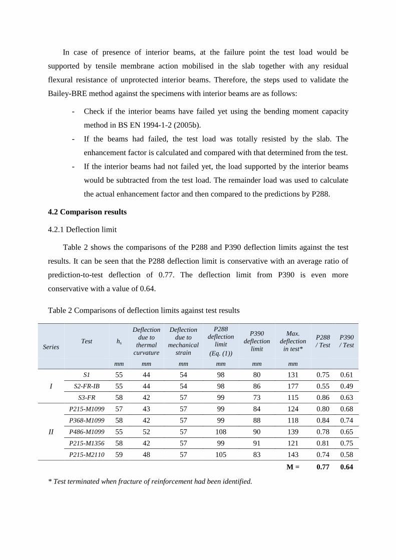
Table 2 shows the comparisons of the P288 and P390 deflection limits against the test
results. It can be seen that the P288 deflection limit is conservative with an average ratio of
prediction-to-test deflection of 0.77. The deflection limit from P390 is even more
conservative with a value of 0.64.
Table 2 Comparisons of deflection limits against test results
Series Test hs
Deflection due to
thermal curvature
Deflection due to
mechanical strain
P288 deflection
limit (Eq. (1))
P390 deflection
limit
Max. deflection
in test*
P288 / Test
P390 / Test
mm mm mm mm mm mm
I S1 55 44 54 98 80 131 0.75 0.61
S2-FR-IB 55 44 54 98 86 177 0.55 0.49 S3-FR 58 42 57 99 73 115 0.86 0.63
II
P215-M1099 57 43 57 99 84 124 0.80 0.68 P368-M1099 58 42 57 99 88 118 0.84 0.74 P486-M1099 55 52 57 108 90 139 0.78 0.65 P215-M1356 58 42 57 99 91 121 0.81 0.75 P215-M2110 59 48 57 105 83 143 0.74 0.58
M = 0.77 0.64
* Test terminated when fracture of reinforcement had been identified.
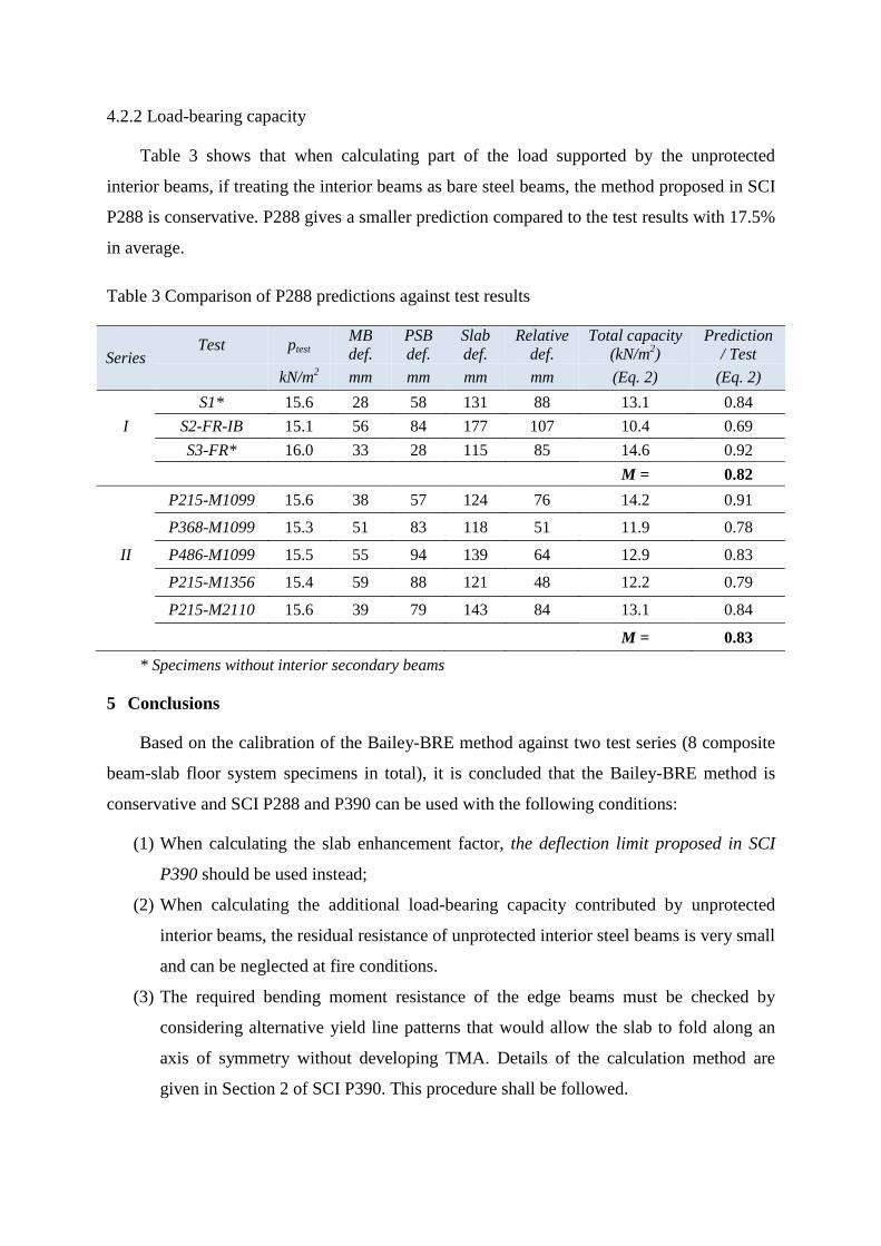
4.2.2 Load-bearing capacity
Table 3 shows that when calculating part of the load supported by the unprotected
interior beams, if treating the interior beams as bare steel beams, the method proposed in SCI
P288 is conservative. P288 gives a smaller prediction compared to the test results with 17.5%
in average.
Table 3 Comparison of P288 predictions against test results
Series Test ptest MB
def. PSB def.
Slab def.
Relative def.
Total capacity (kN/m2)
Prediction / Test
kN/m2 mm mm mm mm (Eq. 2) (Eq. 2)
I S1* 15.6 28 58 131 88 13.1 0.84
S2-FR-IB 15.1 56 84 177 107 10.4 0.69 S3-FR* 16.0 33 28 115 85 14.6 0.92
M = 0.82
II
P215-M1099 15.6 38 57 124 76 14.2 0.91 P368-M1099 15.3 51 83 118 51 11.9 0.78 P486-M1099 15.5 55 94 139 64 12.9 0.83 P215-M1356 15.4 59 88 121 48 12.2 0.79 P215-M2110 15.6 39 79 143 84 13.1 0.84
M = 0.83 * Specimens without interior secondary beams
5 Conclusions
Based on the calibration of the Bailey-BRE method against two test series (8 composite
beam-slab floor system specimens in total), it is concluded that the Bailey-BRE method is
conservative and SCI P288 and P390 can be used with the following conditions:
(1) When calculating the slab enhancement factor, the deflection limit proposed in SCI
P390 should be used instead;
(2) When calculating the additional load-bearing capacity contributed by unprotected
interior beams, the residual resistance of unprotected interior steel beams is very small
and can be neglected at fire conditions.
(3) The required bending moment resistance of the edge beams must be checked by
considering alternative yield line patterns that would allow the slab to fold along an
axis of symmetry without developing TMA. Details of the calculation method are
given in Section 2 of SCI P390. This procedure shall be followed.
It is important to note that the SCI Publications P288 and P390 shall not be used to
replace SS EN 1994-1-1:2004 and SS EN 1994-1-2:2005 in the design of composite steel-
frame buildings under fire conditions. They only provide design guidance on an advanced
calculation method that engineers may use to reduce fire-protection costs. All detailing
requirements of EN 1994-1-1 (2004) should be adhered to.
Acknowledgment
The research presented in this paper was funded by Agency for Science, Technology and
Research (A*Star Singapore). The financial support of A*Star is gratefully acknowledged.
REFERENCES
European Committee for Standardization (CEN) (2004). Eurocode 4. Design of Composite Steel and Concrete Structures. Part 1-1: General Rules and Rules for Buildings, Brussels.
British Standard Institution (BSI) (2003). Structural use of steelwork in building. Part 8: Code of practice for fire resistant design, London.
Bailey, C. G., Lennon, T., and Moore, D. B. (1999). "Behaviour of full-scale steel-framed buildings subjected to compartment fires." Structural engineer London, 77(8), 15-21.
Bailey, C. G., and Moore, D. B. (2000). "Structural behaviour of steel frames with composite floorslabs subject to fire: Part 1: Theory." Structural engineer London, 78(Compendex), 19-27.
Bailey, C. G., and Toh, W. S. (2007). "Behaviour of concrete floor slabs at ambient and elevated temperatures." Fire Safety Journal, 42(6-7), 425-436.
Newman, G. M., Robinson, J. T., and Bailey, C. G. (2006). "Fire Safe Design: A new Approach to Multi-Story Steel-Framed Buildings." SCI Publication P288, The Steel Construction Institute.
Nguyen, T. T. (2014). "Behaviour of Composite Beam-Slab Floor Systems at Elevated Temperatures." Ph.D. Thesis, Nanyang Technological University.
Nguyen, T. T., and Tan, K. H. "Effect of Stiffness of Protected Secondary Edge Beams on the Membrane Behaviour of Composite Beam-slab Systems in Fire " Proc., 8th International Conference on Structures in Fire (SiF'14), Tongji University.
Nguyen, T. T., and Tan, K. H. (2012). "Testing of Composite Slab-beam Systems at Elevated Temperatures." Proc., 7th Int. Conf. on Structures in Fire, Swiss Federal Institute of Technology Zurich, Switzerland, 247-256.
Simms, W. I., and Bake, S. (2010). "TSLAB V3.0 User Guidance and Engineering Update." SCI Publication P390, The Steel Construction Institute.
European Committee for Standardization (CEN) (2005a). Eurocode 3. Design of Steel Structures - Part 1-1: General Rules and Rules for Buildings, Brussels, Belgium.
European Committee for Standardization (CEN) (2005b). Eurocode 4. Design of composite steel and concrete structures - Part 1-2: General Rules - Structural fire design, Brussels, Belgium.