A ROTATING CANTILEVER BEAM FOR DYNAMIC …s2is.org/Issues/v6/n5/papers/paper23.pdf · Abstract-...
19
A ROTATING CANTILEVER BEAM FOR DYNAMIC STRAIN MEASUREMENT AND VIBRATION ANALYSIS BASED ON FBG SENSOR Xixin Jiang 1 , Zude Zhou 1 , Guangrong Bian 1,2 1. Wuhan University of Technology, School of Mechanical and Electronics Engineering, HuBei, Wuhan, China 2. Air Force Service College, Xuzhou, Jiangsu Province, China Email: [email protected] Submitted: July 1, 2013 Accepted: Nov. 30, 2013 Published: Dec. 23, 2013 Abstract- Strain measurement and vibration analysis of a rotating blade are critical for the progress in improvements of the performance of machines. Since traditional sensors and measurement methods have difficulty measuring the rotor blade’s dynamic strain and vibration, the search for new measurement methods has become an urgent task in rotor machine monitoring and diagnosis. This paper presents a new method based on Fiber Briggs Gratings (FBG) for the measurement of strain and estimation of vibrations in a rotating cantilever. The method is based on the fact that the vibration displacement can be expressed in terms of an infinite number of vibration modes and be related to the dynamic strains through strain-displacement relationship. By placing multiple sets of FBG and utilizing an optic coupler, the rotating cantilever beam’s dynamic strain can be measured and vibration can be estimated at the same time. From the results, it can be concluded that this new monitoring method is applicable to the rotating blade. Index terms: Measurement, vibration, strain, FBG, rotating cantilever beam. INTERNATIONAL JOURNAL ON SMART SENSING AND INTELLIGENT SYSTEMS VOL. 6, NO. 5, DECEMBER 2013 2277
Transcript of A ROTATING CANTILEVER BEAM FOR DYNAMIC …s2is.org/Issues/v6/n5/papers/paper23.pdf · Abstract-...

A ROTATING CANTILEVER BEAM FOR DYNAMIC STRAIN
MEASUREMENT AND VIBRATION ANALYSIS BASED ON
FBG SENSOR
Xixin Jiang1, Zude Zhou
1, Guangrong Bian
1,2
1. Wuhan University of Technology, School of Mechanical and Electronics Engineering,
HuBei, Wuhan, China
2. Air Force Service College, Xuzhou, Jiangsu Province, China
Email: [email protected]
Submitted: July 1, 2013 Accepted: Nov. 30, 2013 Published: Dec. 23, 2013
Abstract- Strain measurement and vibration analysis of a rotating blade are critical for the progress in
improvements of the performance of machines. Since traditional sensors and measurement methods
have difficulty measuring the rotor blade’s dynamic strain and vibration, the search for new
measurement methods has become an urgent task in rotor machine monitoring and diagnosis. This
paper presents a new method based on Fiber Briggs Gratings (FBG) for the measurement of strain
and estimation of vibrations in a rotating cantilever. The method is based on the fact that the
vibration displacement can be expressed in terms of an infinite number of vibration modes and be
related to the dynamic strains through strain-displacement relationship. By placing multiple sets of
FBG and utilizing an optic coupler, the rotating cantilever beam’s dynamic strain can be measured and
vibration can be estimated at the same time. From the results, it can be concluded that this new
monitoring method is applicable to the rotating blade.
Index terms: Measurement, vibration, strain, FBG, rotating cantilever beam.
INTERNATIONAL JOURNAL ON SMART SENSING AND INTELLIGENT SYSTEMS VOL. 6, NO. 5, DECEMBER 2013
2277
I. INTRODUCTION
Blades are a critical component in a rotor. Rotating blades always subjected to unexpected
excitations that may weaken a structure due to fatigue or cause catastrophic failure. Thus, strain
measurement and vibration analysis of rotor blades is a critical element for the improvement of
the performance of a rotating machine.
Rotating blades are commonly modeled as rotating beams, because the beam enables researchers
to simply the problem. In early 1920s, Southwell and Gough [1] started to investigate the natural
frequencies of a rotating beam. They suggested an explicit equation that relates the natural
frequency to the rotating frequency of a beam. This equation, which is frequently called the
Southwell Equation, has been widely used by many engineers since it is simple and easy to use.
Later, to obtain more accurate, natural frequencies, a linear, partial differential equation that
governs the bending vibration of a rotating beam was derived by Rubinstein [2]. Applying the
Ritz Method to the partial differential equation, more accurate coefficients for the analytical
model of the Southwell Equation were obtained. In the 1970s, owing to the fast progress of
computing technologies, a large number of papers in which numerical methods were employed
for the modal analysis of rotating structures were published. For instance, Putter and Manor [3]
applied the Assumed Mode Approximation Method for the modal analysis of a rotating beam.
Various other effects on the modal characteristics of rotating beams were also investigated. The
effect of tip mass was considered by Hoa [4] and Hodges [5], elastic foundation and cross-section
variation were considered by Kuo et al. [6], shear deformation was considered by Kokoyama [7]
and Yoo [8]. Using these methods, the modal characteristics of rotating beam could be effectively
analyzed.
However, we need some effective method to prove that the analysis is correct. Measuring the
actual strain/vibration value is significantly important. Current methods, such as the use of an
electrical strain gauge, have too many limitations to apply on the rotor blade. Developing a new
measurement has become a necessity.
FBG(Fiber Bragg Gratings) are sensor elements which are photo-etched into optical fiber using
intense ultraviolet laser beams. After almost two decades of development, FBG sensor
technology is now on the verge of maturity. Generally, FBG have been used for the measurement
of strain and strain-related quantities, such as stress, deformation, temperature and displacement
Xixin Jiang, Zude Zhou and Guangrong Bian, A ROTATING CANTILEVER BEAM FOR DYNAMIC STRAIN MEASUREMENT AND VIBRATION ANALYSIS BASED ON FBG SENSOR
2278

[9,10], etc. The reported applications include monitoring of highways, bridges, and aerospace
components. However, the measurement of strain on a rotating blade using FBG is a great
challenge. In a rotating machine, the difficulty is transmitting signals from the rotor to the stator.
There are several general methods to achieve signal transmission: the slip ring, telemetry, and
FORJ (Fiber Optic Rotary Joints). The slip ring enables the transfer of electrical signals to a
stationary part with bushings running in contact with a rotating ring. This method was used to
observe the dynamic strain of a gas turbine rotor blade [11]. Several difficulties remain. Physical
contact between the bushings and the rotating rings creates electrical noise. In regard to telemetry,
the signals transfer via an IP network or radio waves and more than 10 billion kilometers can be
covered, but limit the speed of measurement. In regard to FORJ (Fiber Optic Rotary Joints), the
signal is transferred between two fibers, one which is rotating, the other is static. Two fibers in a
thin tube are constrained to four degrees of freedom, which creates friction between the tube and
the fibers, thus limiting the speed to rates less than 10000 rpm. Author Kyungmok Kim [12]
proposed another method using five FBG sensors to measure the rotating blades’ dynamic strain.
In his experiment the speed was less than 2000rpm, but the method could overcome the above
difficulties.
FBG is a strain sensor in principle. An electrical strain gauge is another conventional strain
sensor. Generally, when strain sensors are used for evaluation of structural vibration, they can
only detect an approximate vibration in one dominant mode, but not high-precision vibration.
However, the vibration consists of an infinite number of vibration modes and each mode has its
own constant gain. Thus, we could utilize the point to sense the vibration with high accuracy.
Chen-Jung Li and A. Galip Ulsoy[13] used a two strain gauge approach to calculate a beam’s
vibration. In these approaches, the vibration displacement of the structure is represented by a
finite number of dominant modes and each mode has its own constant gain for converting the
displacement components into strain components in this mode. Pavic [14] employed strain
gauges to measure in-plane acceleration for plates and axial acceleration for beams. In this paper,
strain can expressed as spatial derivatives of displacement. By placing multiple sets of strain
gauges, we can measure the displacement vibration.
This paper used the same method in principle as Kyungmok Kim’s method for the measurement
of a beam’s dynamic strain using FBG. Based on the wavelength-strain-displacement relationship
and displacement having multiple modes, the paper developed a method that the vibration of a
INTERNATIONAL JOURNAL ON SMART SENSING AND INTELLIGENT SYSTEMS VOL. 6, NO. 5, DECEMBER 2013
2279

beam can be expressed as the change of FBGs’ wavelength. However, the effect of the higher-
order vibration modes on the overall vibration typically gets smaller and smaller. Therefore, only
the first few dominant modes often need to be considered for the vibration displacement
measurement. This paper presents such a FBG based method for the vibration/strain/stress
measurement of a cantilever.
II. THE PRINCIPLE OF SENSOR AND MEASUREMENT METHOD
A. The working principle of FBG sensor
An FBG is composed of periodic changes of the refractive index that are formed by exposure to
an intense UV interference pattern in the core of an optical fiber. When light from a broad band
source interact with the grating, a single wavelength, know as the Bragg wave length, is reflected
back while rest of the signal is transmitted. An FBG shows sensitivity to strain and temperature
changes. The Bragg condition is expressed as:
2B en (1)
Where B is the Bragg wavelength of FBG; enis the effective refractive index of the fiber core,
and is the grating period.
If the grating is exposed to external perturbations, such as strain and temperature, the Bragg
wavelength will change. By measuring the wavelength changes accurately, physical properties,
such as strain and temperature, can be measured. The shift of a Bragg wavelength due to strain
and temperature and pressure can be expressed as:
BT P
B
K KTKP (2)
WhereK is the wavelength sensitivity coefficient for strain; TK
is the wavelength sensitivity
coefficient for temperature, and PK is the wavelength sensitivity coefficient for pressure. With
the assumption of no pressure changes and no temperature changes, we can measure the strain
from wavelength shift as:
1
1
B
e B
(3)
Where the e is the strain-optic coefficient of the optical fiber.
B. The working principle of rotating cantilever beam dynamic strain measurement
Xixin Jiang, Zude Zhou and Guangrong Bian, A ROTATING CANTILEVER BEAM FOR DYNAMIC STRAIN MEASUREMENT AND VIBRATION ANALYSIS BASED ON FBG SENSOR
2280

Figure 1 shows the working principle for measuring dynamic, rotating cantilever strain: the FBG
is mounted on a rotating beam, broadband light is emitted from a light source and propagated
along an optical fiber via a rotary optic coupler (the rotary optic coupler is comprised of two
parts,a rotor and a stator. The coupler enables the light to travel in parallel and allows optical
signal transmissions between the rotor and the stator), the FBG reflects a specific wavelength of
light that is checked by an interrogator. If the FBG is exposed to an external perturbation, such as
strain and/or temperature changes, the Bragg wavelength is changed, then, data about the rotating
beam is collected.
Figure 1. Illustration of the working principle of measuring the dynamic strain on a rotating,
cantilevered beam
Figure 2. Working principle of rotary fiber coupler
Figure 2 shows the principle of fiber coupler, the fiber coupler consists of two C-lenses and the
two C-lenses have a 2mm air gap between them. One C-lens is axially installed at the center of
the shaft and the other is stationary and coaxially aligned with the first. The C-lenses change the
light in the fiber to a collimated beam of parallel light, and the collimation light is transmitted
INTERNATIONAL JOURNAL ON SMART SENSING AND INTELLIGENT SYSTEMS VOL. 6, NO. 5, DECEMBER 2013
2281
through the air gap, then, the optical signal can be transmitted between the stationary part and the
rotating part.
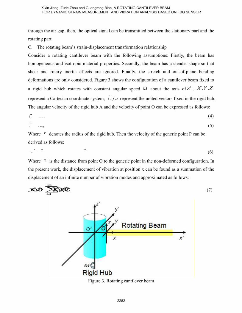
C. The rotating beam’s strain-displacement transformation relationship
Consider a rotating cantilever beam with the following assumptions: Firstly, the beam has
homogeneous and isotropic material properties. Secondly, the beam has a slender shape so that
shear and rotary inertia effects are ignored. Finally, the stretch and out-of-plane bending
deformations are only considered. Figure 3 shows the configuration of a cantilever beam fixed to
a rigid hub which rotates with constant angular speed about the axis of Z , , ,X Y Z
represent a Cartesian coordinate system, , ,i j k represent the united vectors fixed in the rigid hub.
The angular velocity of the rigid hub A and the velocity of point O can be expressed as follows:
A k (4)
ov r j (5)
Where r denotes the radius of the rigid hub. Then the velocity of the generic point P can be
derived as follows:
( )pvui rxujwk (6)
Where x is the distance from point O to the generic point in the non-deformed configuration. In
the present work, the displacement of vibration at position x can be found as a summation of the
displacement of an infinite number of vibration modes and approximated as follows:
1
(,) ()()i i
i
yxt Yxft
(7)
Figure 3. Rotating cantilever beam
Xixin Jiang, Zude Zhou and Guangrong Bian, A ROTATING CANTILEVER BEAM FOR DYNAMIC STRAIN MEASUREMENT AND VIBRATION ANALYSIS BASED ON FBG SENSOR
2282

Where ( )iY x and ( )if t are the mode shape and time response of the ith mode, respectively. By
using Hooke’s law, the relationship of stress-moment for pure bending, we obtain:
2
22
21
(,)( )(,) ()(,)
()x izx i
i
yxtEI rxt YxMxtr xr ft
EEI EI x
(8)
Where x and x are the axial strain along the x-axis at position x and the distance r above the
neutral axis, zM is the moment about the z-axis.
Thus, a new method is developed to detect the vibration using equations (7) and (8). Considered
these three cases, the first: taking into account one mode, the second: two modes, the third: n
modes.
CASE A: The first mode in isolation
Taking into account only one mode, we can express the displacement as:
1 1(,) () ()yxt Yxf t (9)
Thus, assuming the first mode is dominant, the displacement at position dx can be expressed as
the following equation:
1 1 1( ,) ( ) ()dyxt Yxft (10)
The strain at the position 1x can be approximated as:
2
1 11 12
()(,) ()x
Yxxt r ft
x
(11)
Substituting Equation (11) into Equation (10), we obtain:
1,1 2
1 11
2
( ,) ()
()(,)
dd
x
yxt Yxk
Yxxtr
x
(12)
This is a coefficient ratio with no relation to time.
We can obtain the coefficient ratio by experimental modal testing or solving the eigenvalue
problem mentioned above for the first mode shape of the system, the displacement at position dx
can be calculated as the product of measured strain and coefficient ratio. That is:
1 1 112 2
11 11 1
2 2
() () ()1(,) (,)
() ()1
Bd x
e B
Yx Yx tyxt xt
Yx Yxr rx x
(13)
INTERNATIONAL JOURNAL ON SMART SENSING AND INTELLIGENT SYSTEMS VOL. 6, NO. 5, DECEMBER 2013
2283

Where ( , )dy x t is the measured displacement vibration. However, the actual measured strain is
contributed by an infinite number of vibration modes, the measurement error can be expressed by
112
11 1
2
1
211 1
2
()( ,) ( ,) ( ,) () ()
( )
() 1() ()
( )1
d d x i i
i
Bi i
ie B
Yxy yx t yx t xt Yxf t
Yxr
x
YxYxf t
Yxr
x
(14)
From Equation (13), it can be seen that 1x should be chosen away from the location where
2
1 11 2
()(,)0, 0x
Yxxt
x
, for example , at x L , thus, we can improve sensitivity .
CASE B: The first and second modes
To test the first and second modes, we put two sets of strain gauges at 1 2,x x , than, we can express
the displacement as:
1 1 2 2(,) ()() ()()yxt YxftYxft (15)
Thus, assuming the first and second mode is significant, the displacement at position dx can be
expressed as following equation:
1 1 2 2(,) ()() ()()d d dyxtYxftYxft (16)
the strain at the position 1x can be approximated as:
2 2
11 211 1 22 2
() ()(,) () ()x
Yx Yxxtr ftr ft
x x
(17)
the strain at the position 2x can be approximated as:
2 2
12 222 1 22 2
() ()(,) () ()x
Yx Yxxtr ftr ft
x x
(18)
Then, we obtain:
2 2
11 21
2 21 1 1
2 22 2 212 22
2 2
() ()
(,) () ()
(,) () ()() ()
x
x
Yx Yxr r
xt ft ftx xK
xt ft ftYx Yxr rx x
(19)
Xixin Jiang, Zude Zhou and Guangrong Bian, A ROTATING CANTILEVER BEAM FOR DYNAMIC STRAIN MEASUREMENT AND VIBRATION ANALYSIS BASED ON FBG SENSOR
2284

K is the transformation matrix which converts ( )f t to ( , )x t
Substituting Equation (19) into Equation (16), we obtain:
12 2
1 1 2 1
2 211
1 2 1 2 2 222 1 2 2 2
2 2
1
1 1
1 2
2
2
() ()
(,)()( ,) ( ) ( ) ( ) ( )
(,)() () ()
1
1() ( )
()1
1
x
d d d d d
x
B
e B
d d
B
e B
Yx Yxr r
xtft x xyxt Yx Yx Yx Yx
xtft Yx Yxr r
x x
t
Yx Yx Kt
(20)
the measurement error can be obtained by Equation (21):
11
1 2
12
(,)(,)(,)()() ()()
(,)
x
d d d d i i
ix
xtyyxtyxtYxYxK Yxft
xt
(21)
CASE C:The first n modes
Following the same procedures, the measurement method can extend to the first dominant n
vibration modes, where the real value of n depends on accuracy. In this case, n sets of FBG need
to be considered, the displacement measured at position dx can be obtained by:
1
2
1 2
22 2
11 1 2 1
2 2 2
22 2
21 2 2 2
2 2 21 2
2 2 2
1 2
2 2 2
( )
( )( , ) ( ) ( ) ( )
( )
( )( ) ( )
( )( ) ( )
( ) ( ) ( )
( ) ( ) ( )
d d d n d
n
n
n
d d n d
n n n n
f t
f ty x t Y x Y x Y x
f t
Y xY x Y xr r r
x x x
Y xY x Y xr r r
Y x Y x Y x x x x
Y x Y x Y xr r r
x x x
1
1
2
1
2
1 2
( , )
( , )
( , )
( , )
( , )( ) ( ) ( )
( , )
x
x
x n
x
x
d d n d
x n
x t
x t
x t
x t
x tY x Y x Y x K
x t
(22)
INTERNATIONAL JOURNAL ON SMART SENSING AND INTELLIGENT SYSTEMS VOL. 6, NO. 5, DECEMBER 2013
2285

The actual measurement error can be obtained by:
122 2
111 21
2 2 2
122 2
212 2 222 2 2
1 2
2 2 2
1 2
2 2 2
(,) (,)
()() ()
(,)()() ()
(,)() () ()
(,() () ()
d d
n
x
nx
d d n d
x n
n n n n
yyxt yxt
YxYx Yxr r r
x x x xtYxYx Yx
xtr r rYx Yx Yx x x x
xYx Yx Yx
r r rx x x
1
()()
)
i i
i
Yxft
t
(23)
III. SIMULATION AND EXPERIMENT
A. Simulation
This section presents the simulation result based on the ANSYS. As show the Figure 1, a
cantilevered beam fixed to a rigid hub, which rotates with constant angular speed about axis
of Z. The cantilevered beam is assumed to be the same as same the one in section II.. In regard to
the different constant angular speeds, the cantilevered beam has a different natural frequency, but
the mode shapes are almost similar, as show in Figure 4. The blue line represents the second
strain mode at 2000rpm. The denotation represents the second strain mode at 0 rpm.
Figure 4. The mode shapes of the cantilever beam
So, we chose the static cantilevered beam as a method of calibration to estimate measurement
error. A simply support cantilever beam is shown in Figure 5.
Xixin Jiang, Zude Zhou and Guangrong Bian, A ROTATING CANTILEVER BEAM FOR DYNAMIC STRAIN MEASUREMENT AND VIBRATION ANALYSIS BASED ON FBG SENSOR
2286

Figure 5. A cantilever beam with an applied load sinP t
Its physical and mechanical properties are list in Table 1. The natural frequencies were obtained
by a simulation.
Table 1: The physical and mechanical properties of the beam
Physical properties Mechanical properties
Density 7850kg/m3 Young Modulus 2E+11pa
Thicknes
s
6mm Poisson Ratio 0.3
Length 305mm 1st and 2
nd natural
frequencies
60.199Hz and
375.52 Hz
Width 25mm 3rd natural
frequencies
1045.6Hz
Figures 6~8 show the first three displacement modes, Figures9~11 show the first three strain
modes. We can conclude from Figure 12 that the first FBG should be placed at 0x , the second
FBG should be placed at 159.3x mm , the third FBG should be placed at 90.4x mm , so
that we have the largest sensitivity for detecting the various strains.
Figure 6 The first mode shape Figure 7 The second mode shape
INTERNATIONAL JOURNAL ON SMART SENSING AND INTELLIGENT SYSTEMS VOL. 6, NO. 5, DECEMBER 2013
2287

Figure 8 The third mode shape Figure 9 The first strain mode shape
Figure 10 The second strain mode shape Figure 11 The third strain mode shape
Figure.12 The strain on cantilever ( the first strain mode shape,
The second strain mode shape, the third strain mode shape)
B. Experiment
1. Experimental evaluation of FBG sensors and piezoelectric accelerator for monitoring
vibration
This section presents the experimental program for evaluation the performance of FBG-based
strain sensors and piezoelectric accelerator for beam’s vibration measurement. The experiments
were conducted in two and three modes in order to verify the proposed measurement
methodology.
Xixin Jiang, Zude Zhou and Guangrong Bian, A ROTATING CANTILEVER BEAM FOR DYNAMIC STRAIN MEASUREMENT AND VIBRATION ANALYSIS BASED ON FBG SENSOR
2288

2. Experimental-1 set-up and result
The laboratory tests were performed on a simple support cantilever. The FBG-based strain
gauges, which were manufactured by the Wuhan University of Technology, China, had a gauge
length of 5mm. The acceleration vibration was measured by a piezoelectric accelerometer (4508-
B, Bruel & Kjaer) in the frequency range 10~139 kHz. There are 3 measuring points of FBG and
1 acceleration sensors on the beam which were employed to record the beam’s surface train and
the displacement vibration simultaneously. The sensors’ position is shown in Figure 14. High
strength epoxy adhensive RS 159-3957 was used for bonding the strain measuring FBG sensor
for beam. Figure 13 show a close view of various sensors bonded on beam, Figure 14 shows the
location of FBGs on beam.
Figure. 13 An experimental rig for measuring strain
Figure.14 The beam and the FBGs’ positions
Figure 15 shows the experimental setup for measuring the response of the beam. The beam was
clamped rigidly at one end. An electric-driven shaker, used to generate external excitation to the
beam, is attached to the bottom of the beam at a position 5mm from the left end as indicated in
the drawing. The strain measured by FBG sensors and the displacement measured by the
piezoelectric accelerometer were recorded simultaneously.
INTERNATIONAL JOURNAL ON SMART SENSING AND INTELLIGENT SYSTEMS VOL. 6, NO. 5, DECEMBER 2013
2289

Figure 15. The whole experimental set-up
The FBG sensors were wired to an interrogator which was controlled using a personal computer.
In order to sense the first to the third vibration modes, four sets of FBG were mounted at
locations 8x mm , 90.4x mm , 159.3x mm and 215.3x mm , respectively, to detect the
strain signals. The positions of sensors were determined by the method presented in section III. A.
Note that the first set was mounted at 8x mm instead of 0x mm due to the dimensions of
gauges.
Assume that strain and deflection signals are composed of first-three modes, neglecting the
higher modes. The coefficient, listed in Table 2, is
2
2
( )i iY x
x
, come from mode shape analysis, by
substituting these coefficient into Equation (22) , we obtain the estimated displacement for the
three modes.
Table 2 The physical and mechanical properties of the beam
1# POINT 2#POSITION 3#POSITION
First mode 0.01465 0.0098 -0.0053
Second mode 0.0892 -0.0284 0.0724
Third mode 0.2422 -0.1814 0.0292
For example, when the cantilevered beam was excited by a harmonic force of 30 Hz, the FBG’s
strain response was 72.53µε, 42.63µε, 23.63µε, respectively. The displacement of A point on
beam (Figure.14) is:
Xixin Jiang, Zude Zhou and Guangrong Bian, A ROTATING CANTILEVER BEAM FOR DYNAMIC STRAIN MEASUREMENT AND VIBRATION ANALYSIS BASED ON FBG SENSOR
2290
1
1 172.53
10.2213027500.014650.08920.24221 1
6.904-1.17977 0.8665 0.0098-0.0284-0.1814 42.631-0.221305854
0.00530.07240.02921 1
23.631-0.221307714
0.479m
The measurement error of beam tip can be obtained by an accelerator:
0.4790.44100%8.86%
0.44
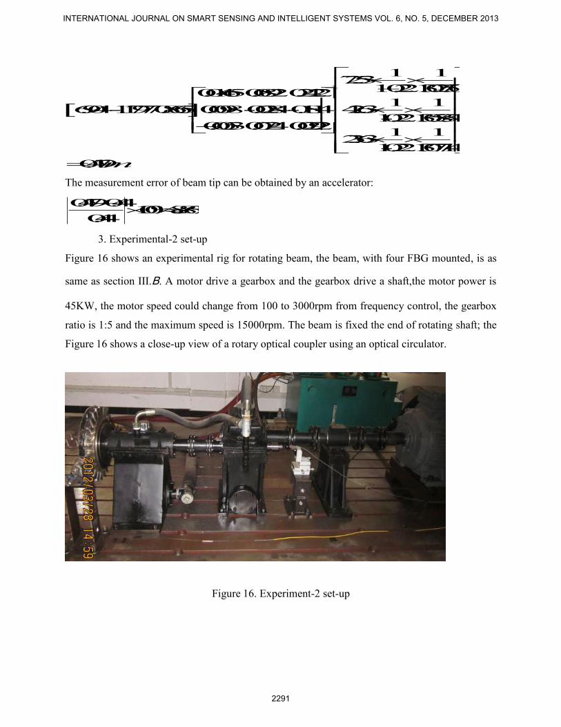
3. Experimental-2 set-up
Figure 16 shows an experimental rig for rotating beam, the beam, with four FBG mounted, is as
same as section III.B. A motor drive a gearbox and the gearbox drive a shaft,the motor power is
45KW, the motor speed could change from 100 to 3000rpm from frequency control, the gearbox
ratio is 1:5 and the maximum speed is 15000rpm. The beam is fixed the end of rotating shaft; the
Figure 16 shows a close-up view of a rotary optical coupler using an optical circulator.
Figure 16. Experiment-2 set-up
INTERNATIONAL JOURNAL ON SMART SENSING AND INTELLIGENT SYSTEMS VOL. 6, NO. 5, DECEMBER 2013
2291

IV. RESULTS AND DISCUSSION
A. Results
This section presents the results of strain measurements and an evaluation of displacement
vibration of rotating a beam, by gradually increasing the rotational speed to 1200rpm andthe 3-
FBG’s wavelengths were simultaneously recorded at a sampling rate of 2kHz.
Figure 17 shows micro strain of the FBG sensor mounted at 8mm of beam in range of 10-1200
rpm. Rotational speed was controlled by a motor controller. Rotational speed started at10 rpm, at
10~15 second intervals, to 1200rpm at the end. From Figure 17, the dynamic strain shows
oscillating vibration around a mean value. The mean strain decreases with rotational speed, which
means the beam was stretched under centrifugal force. The oscillating vibration means that
experiment was carried out under an elastic strain condition.
Figure18 shows he measured dynamic strain against time at constant rotational speeds
(approximately 325 rpm, with the same FBG sensor in Figure 17). The results of spectrum
analysis show that 7.26 Hz, 14.53Hz, 55Hz cycles existed (Figure. 19). These means are doubled
in frequency relating to rotating speed(7.26 Hz, 14.53Hz) and a frequency related to natural
frequency of a cantilevered beam(55Hz, the simulation results is 60.199 Hz in section Ⅲ , the
difference came from the boundary condition ).
Figure 17 Strain on 1# FBG in range 0~900rpm Figure 18 Strain on 1# FBG at 325rpm
Xixin Jiang, Zude Zhou and Guangrong Bian, A ROTATING CANTILEVER BEAM FOR DYNAMIC STRAIN MEASUREMENT AND VIBRATION ANALYSIS BASED ON FBG SENSOR
2292

Figure. 19 Spectrum analysis of Figure 17 Figure. 20 The vibration estimation of
the beam's tip
Figure 20 shows the vibration estimation of A point of beam at constant rotational speeds 325
rpm, blue line represent the case considering only the first three modes. From experimental-1, we
know that the measurement error approximately 8.86%
B. Discussion
The errors came from the following causes.
1) The clamping condition of rotating cantilever beam does not yield a perfect fixed boundary
condition.
2) The errors came from the FBG. Ideally, the sensors are moved to a more advantageous
position. However, due to size of the FBG, the signals from the FBG are average values of a
surface range. On the other hand, the sensitivity of the FBG is the source of the errors.
3) The relative error comes from the piezoelectric accelerometer which was used to calibrate the
displacement vibration. To achieve higher displacement measurement, a sensor with higher
sensitivity could be used.
4) 8.86% error is for consider only three. Due to measuring three modes there was an error of
8.86%. By taking more modes into account, errors will be reduced.
5) Since the location of the FBG is calculated based on analytical modes, it induced some errors.
V. CONCLUSIONS
The method of using an FBG to measure dynamic strain and estimate the displacement vibration
of a rotating, cantilevered beam has been validated. This method is based on the fact that the
vibration displacement can be expressed in terms of an infinite number of vibration modes and be
related to the dynamic strains through the strain-displacement relationship. From the results, it
can be concluded that this new monitoring method can be applied to a rotor blade.
INTERNATIONAL JOURNAL ON SMART SENSING AND INTELLIGENT SYSTEMS VOL. 6, NO. 5, DECEMBER 2013
2293

REFERENCES
[1] Southwell R, Gough F, “The free transverse vibration of airscrew blade”, British A.R.C.
Reports and Memoranda, Vol. 766, 1921.
[2]Nathan Rubinstein, James T. Stadter, “Bounds to bending frequencies of a rotating beam”,
Journal of the Franklin Institute, Vol. 294, 1972, pp.217-229.
[3]Putter S and Manor H. “Natural frequencies of radial rotating beams”, Journal of Sound and
Vibration, Vol. 56, 1978; pp. 175-185.
[4]S.V. Hoa , “Vibration of a rotating beam with tip mass”, Journal of Sound and Vibration,
Vol. 72, 1979; pp. 369-381.
[5]S.V. Hoa, D.H. Hodges, M.J. Rutkowski, “Comments on “vibration of a rotating beam with
tip mass” ”, Journal of Sound and Vibration , Vol. 72,1980, pp.547-549.
[6]Kuo, Tzung, Hurng Wu, Sen Yung Lee, “Bending vibration of a rotating non-uniform beam
with tip mass and an elastically retrained root”, Computers & Structures, Vol. 42,1992:pp.229-
236
[7]T. Yokoyama, “Free vibration characteristics of rotating Timoshenko beams”, International
Journal of Mechanical Sciences, Vol. 30, 1988; pp.743-755
[8] H. H.Yoo, S. H.Shin, “Vibration analysis of rotating cantilever beams”, Journal of Sound and
Vibration , Vol. 212, 1998,pp.807-828.
[9] Shu, X., Liu, Y., Zhao, D, Gwandu, B., Floreani, F., Zhang, L.; Bennion, “Dependence of
temperature and strain coefficients on fiber grating type and its application to simultaneous
temperature and strain measurement”, Optics Leters, Vol. 27, 2002, pp.701-703.
[10]Guru Prasad, A.S., “Measurement of stress-strain response of a rammed earth prism in
compression using fiber bragg grating sensors”. International Journal on Smart Sensing and
Intelligent Systems, September 2011, pp 376-387,
[11]S. Bhalla , Y.W. Yang , J. Zhao, C.K. Soh. “Structural health monitoring of underground
facilities-Technological issues and challenges”, Tunnelling and Underground Space Technology,
Vol. 20, 2005, pp.487-500
Xixin Jiang, Zude Zhou and Guangrong Bian, A ROTATING CANTILEVER BEAM FOR DYNAMIC STRAIN MEASUREMENT AND VIBRATION ANALYSIS BASED ON FBG SENSOR
2294

[12]Kyungmok Kim, Jong Min Lee, Yoha Hwang, “Determination of engineering strain
distribution in a rotor blade with fibre Bragg grating array and a rotary optic coupler” Optics and
Lasers in Engineering, Vol. 46, 2008, pp.758-762.
[13]Chen-Jung Li and A. Galip Ulsoy, “High-Precission Measurement Of Tool-Tip Displacement
Using Strain Gauges In Precision Flexible Line Boring”, Mechanical Systems and Signal
Processing, Vol. 13(4), 1999, pp.531-546
[14]G. Pavic, “Measurement of vibrations by strain gauges, Part I: theoretical basis”, Journal of
Sound and vibration, Vol. 102, 1985, pp.153~163.
INTERNATIONAL JOURNAL ON SMART SENSING AND INTELLIGENT SYSTEMS VOL. 6, NO. 5, DECEMBER 2013
2295