A Robust Inexpensive Multi-Purpose Robotic Armpeople.csail.mit.edu/alana/Lafferty_thesis.pdf · A...
37
A Robust Inexpensive Multi-Purpose Robotic Arm Alana Lafferty Bachelor’s Thesis Advisors: Professor Rodney Brooks and Dr. Una May O’Reilly May 23, 2005
Transcript of A Robust Inexpensive Multi-Purpose Robotic Armpeople.csail.mit.edu/alana/Lafferty_thesis.pdf · A...

A Robust Inexpensive Multi-Purpose Robotic Arm
Alana Lafferty Bachelor’s Thesis
Advisors: Professor Rodney Brooks and Dr. Una May O’Reilly May 23, 2005

1
Table of Contents 1.0 Background............................................................................................................. 2 2.0 Design Goals........................................................................................................... 2
2.1 Mechanical Subsystem........................................................................................ 3 2.2 Electrical Subsystem........................................................................................... 6 2.3 Software Subsystem............................................................................................ 6
3.0 Results and Discussion ........................................................................................... 7 3.1 Mechanical Subsystem........................................................................................ 7 3.2 Electrical and Software Subsystems ................................................................. 11
4.0 Future Work .......................................................................................................... 12 Appendix I: Construction Details ..................................................................................... 13 Appendix II: Electronics Schematics................................................................................ 25 Contributions by Others.................................................................................................... 35 References......................................................................................................................... 36 Index of Figures Figure 1: Complete Block Diagram of the Robotic Arm Electronic, Mechanical, and
Software System ......................................................................................................... 3 Figure 2: As described in the Edsinger Weber paper3, the series elastic actuator places an
elastic spring element between the motor output and the load ................................... 4 Figure 3: The inside of a springbox with the embedded springs in an initial equally pre-
compressed state from the paper on a simple, scalable force actuator2. ..................... 4 Figure 4: On the left is a CADD model of the hand designed by Eduardo Torres-Jara and
on the right is the CADD model of the arm for this project ....................................... 5 Figure 5: Solidworks model of two degree-of-freedom robotic arm.................................. 5 Figure 6: PID Control Loop for Motor velocity ................................................................. 6 Figure 7: Photo of Robot Arm System ............................................................................... 7 Figure 8: A Force Diagram showing the relation between motor torque and tension in the
cables and forces for the springs along with equation 5, describing this relation ...... 9 Figure 9: DSP Board and H-bridge fully assembled for robot arm system...................... 11

2
1.0 Background Robotics is a growing field with applications in the defense, industrial, and consumer markets. Manipulation is a very important aspect of robotics, which is necessary for accomplishing simple and complex tasks from painting cars in a factory to lifting victims out of rubble. No ideal solution to manipulation has been identified yet that maximizes robustness and minimizes cost. Some particularly important considerations in manipulation are compliance and high fidelity force control. Force sensing and compliance at each robot joint can allow a robot to safely interact in unstructured and unfamiliar environments. Additionally, force control is an important innovation to have because of back driveability. When, a force is exerted on the arm itself, a traditional robotic arm would back drive its motors; whereas, with force control using series elastic actuation, there is a compliance which will prevent the motors from being back driven. Previous work done in the area that recognized these considerations include the invention of the series elastic actuator, as described in Matthew Williamson’s technical report1 for the Artificial Intelligence Laboratory at MIT in 1995. A series elastic actuator is simply an actuator coupled with a spring to create compliance and the ability to use force control rather than position control. The additional use of a feedback controller using sensors such as strain gauges or potentiometers that measure spring deflection allows for precise force control. An variation of the series elastic actuator is described in a paper called “A Simple and Scalable Force Actuator”2 by Eduardo Torres-Jara and Jessica Banks. This approach will be described in greater detail later in this proposal. A third variation of force sensing is described in a report3 about Aaron Edsinger’s project called Domo. Other considerations about robotic arms are the cost of off-the-shelf robotic arms compared to robustness. Robotic arms for the hobbyist are inexpensive but lack robustness due to the use of plastic gears and simple dc motors without series elastic actuation. Industrial robotic arms are robust, yet extremely expensive and are not affordable for typical student university research projects. Current robotic arms in research contexts can also be very expensive when the arms are designed with many complex parts that have to be outsourced in addition to expensive actuators and sensors. Therefore, an inexpensive robust robotic arm would be a very useful development with many potential applications.
2.0 Design Goals The overall goal of this project is to design and implement a complete system for a robust and inexpensive two degree-of-freedom robotic arm. The original reason for building this arm was for it to be mounted to the Segway robot called Cardea, which was built during the summer of 2003 in the Humanoid Robotics Laboratory within the Artificial Intelligence Laboratory at MIT. Cardea was designed to navigate corridors, locate doorways, open doors, and walk through the doorways. This original arm was

3
then mounted horizontally in order to locate walls accurately. Working on Cardea’s arm raised awareness and questions as to future or alternative robotic arm systems.
Elements involved in designing a complete robotic arm system include mechanical design, fabrication, and assembly; electronics design, assembly, and testing; and software implementation. An overall block diagram is shown in Figure 1. Specific details of the mechanical, electrical, and software design choices and details of the project will be discussed in the following sections.
Figure 1: Complete Block Diagram of the Robotic Arm Electronic, Mechanical, and Software System
2.1 Mechanical Subsystem The mechanical goal of this project is to design and build a two degree-of-freedom robotic arm. The specific desired degrees of freedom are one degree of freedom for the shoulder and one degree of freedom at the elbow.
Additionally, the use of force feedback was chosen since the arm will be mounted on the Segway robot, where a traditional robotic arm without compliance would cause the motors to be back driven when the arm bumped into an obstacle. Specifically, the simple and scaleable force actuator model developed by Eduardo Torres-Jara was chosen based on its ability to use inexpensive potentiometers and springs and the possibility to machine all necessary parts in the CSAIL machine shop. This model was chosen over the traditional series elastic actuator which has two available types, linear and rotary. A model of a series elastic actuator is shown in Figure 2.

4
Figure 2: As described in the Edsinger Weber paper3, the series elastic actuator places an elastic spring element between the motor output and the load
Linear series elastic actuators require expensive ball screws that limit the size of the system in which they are placed. Rotary series elastic actuators require difficult to fabricate torsional springs and cumbersome strain gauges. The simple and scaleable force actuator model maintains the benefits of series elastic actuation including compliance and force control, while limiting the negative aspects of series elastic actuators. The simple scaleable force actuator model utilizes an actuator which is connected to a shaft, with a cable wrapped around the shaft that is connected to two springs. A picture of this model from the Torres-Jara and Banks paper2 can be found in Figure 3.
Figure 3: The inside of a springbox with the embedded springs in an initial equally pre-compressed state from the paper on a simple, scalable force actuator2.
Another reason for choosing this form of force actuation is the ability to impart
series elastic actuation to any joint. It is compact, easy to build and miniaturized for joint mounting. This model is currently being utilized in a hand designed by Eduardo Torres-Jara. Some modifications on the design for the fingers of the hand have been used for this robotic arm as a result of the larger scale and the desire for the arm to be as simple and inexpensive as possible. A comparison of the Solidworks5 model of the hand with the design of the arm can be seen in Figure 4. Neither model, however, shows the cables which connect the joints with the actuators. Figure 5 details the parts in the robotic arm system for clarity.
shaft
springs

5
Figure 4: On the left is a CADD model4 of the hand designed by Eduardo Torres-Jara and on the right is the CADD model of the arm for this project
Figure 5: Solidworks model of two degree-of-freedom robotic arm
Motor
Motor
Potentiometer
Potentiometer
Spring Box
Spring Box

6
2.2 Electrical Subsystem The electrical subsystem is dependant on the mechanical subsystem. Therefore,
the electronics were chosen to complement the already selected mechanical design (see Figure 1).
Motors need to have power and the typical way to provide power to DC motors is by using Pulse Width Modulation (PWM). This is typically accomplished with an H-bridge circuit which provides an output of a pulse train with a variable duty cycle in order to run the motor at different speeds. Specifically, I chose an H-bridge designed by Jamie Rollins, though the choice of which H-bridge to use is inconsequential. See Appendix II for schematics and details about the H-bridge.
Choosing a microcontroller was a much more complex decision process. A DSP board (Digital Signal Processor) was selected for the following reasons: 1) flexibility, 2) speed, 3) multiple input ports for potentiometers and other sensors that might be used in the future, and; 4) direct control for PWM and direction for the motors. The potentiometers are used to measure deflection at the joints. The specific DSP board that is being used in this project was designed by Eduardo Torres-Jara and can be found in Appendix II.
2.3 Software Subsystem
The DSP can be programmed in C or Assembly using the CodeWarrior software6. This software includes the low level control for the motors and sensors as well as the high level PID (proportional integral derivative) loop, which is shown in Figure 6. This is implemented to demonstrate zero force and force for the robot arm. The fourier transform which describes a PID control loop system is H(s) = K1+ K2/S + K3s.
Figure 6: PID Control Loop for Motor velocity

7
3.0 Results and Discussion The current state of the robot arm is a completely assembled robotic arm with fully functional hardware. The arm, however, has not yet been programmed with code, so its force feedback capabilities cannot be demonstrated. Therefore, most of the functionality is still theoretical. Figure 7 shows a photo of the current state of the robot arm system.
As a result of working on the robotic arm project, I have gained tremendous knowledge in both mechanical and electrical engineering design and the tradeoffs associated with each one.
Figure 7: Photo of Robot Arm System
3.1 Mechanical Subsystem
Within the series elastic actuator design choice, there are many open design options. Complete detail of the construction and parts in the arm can be found in Appendix I. Particularly important decisions involved choosing the motors, choosing the springs, determining how to wrap the cables around the wheels, and designing the boxes that contain the springs. Figure 5 shows the mechanical subsystem design.
The motors need to provide sufficient torque to compensate for the weight of the arm as well as to provide tension in the cables to move the arm. The first characteristic to calculate when selecting a DC motor is the power requirement. The power required for each motor in the arm is determined by the maximum torque and angular velocity of the components actuated by the motor.
ωτ ⋅= maxP , (1) where ω is the angular velocity. The angular velocity is the minimum speed required for acceptable performance; for the elbow, 2π rad/s is an acceptable speed, and π rad/s is adequate for the shoulder. The maximum torque on the motor occurs when the arm is in the horizontal position because the torque caused by gravity is the greatest. This torque is

8
equal to the moment of inertia about the motor shaft, J, times the acceleration due to gravity, 9.8 m/s2:
gJ ⋅=maxτ . (2) The moment of inertia, J, is equal to the sum of the moments of each element rotating around the motor shaft:
∑ ⋅=i
ii rmJ , (3)
where mi is the mass of a component and ri is the distance from its center of mass to the motor shaft. Combining equations 1, 2, and 3, the power required for each motor is:
∑ ⋅⋅⋅=i
ii rmgP ω . (4)
For the elbow joint, the net moment of inertia is 0.05 kg·m, so the minimum power required is 3.08 watts. The net moment of inertia around the shoulder joint is 0.12 kg·m, yielding a minimum power requirement of 3.69 watts. With a safety factor of roughly 2, I chose motors for the elbow and shoulder joints that are rated at 6 and 7 watts respectively. The gearing for the two motors is a combination of the gearbox built onto the motor, the motor coupling, and the pulleys. The gear trains reduce the angular velocity of the motor to the desired rotational speed of the arm components. The ratio of the diameters of the pulleys to the motor couplings is approximately 1.75:1. The operating speeds of the 6 and 7 watt motors are 9800 rpm and 7300 rpm respectively. The desired reduction ratio of the gearbox is equal to the motor velocity divided by the pulley ratio divided by the desired velocity. This yields desired gearbox ratios of 139:1 for the shoulder and 93:1 for the elbow. The actual gearboxes on the motors are 144:1 and 88:1 respectively.
From the motor torque, the cable tension can be derived. Figure 8 shows the relation between the motor torque and cable tension.

9
rTT 0
21τ
=− (5)
Figure 8: A Force Diagram showing the relation between motor torque and tension in the cables and forces for the springs along with equation 5, describing this relation
1111 xkFT == . (6)
2222 xkFT == . (7)
kxr20 =τ . (8)
k1 = k2 = k (9) T1= -T2 (10) Given equations 6 and 7 and knowing the motor torque, the spring constants can be chosen. Additionally, the compression distance and length of the spring can be picked by adding equation 8 where r is the radius of the motor shaft coupling, τo is the output torque, k is the spring constant and x is the distance the spring is compressed
The choice to wrap the cables at the shoulder around the joint shaft wheel five times each was to dampen the effect of the springs. The advantage of a spring and damper system over a typical spring system is making the overshoot oscillation of the spring negligible. This is because friction is a function of how many times the cable is

10
wrapped around the wheel. The added friction means the motor needs to provide more torque, however.
The boxes that contain the springs are adjustable with a screw which allows for easy tensioning of the cables and pre-compression of the springs. The spring box is a very important part of the system that allows the series elastic actuation to work. Originally, the spring boxes were machined out of aluminum, which made the system too heavy, therefore they were replaced by delryn spring boxes. A major tradeoff in design is weight versus strength. Aluminum is far stronger than delryn; however, delryn is much lighter. The lighter weight was important for the motors to be able to provide sufficient torque.
Materials used for the arm which contribute to its relatively low cost as well as to its durability are aluminum, acrylic, and delryn. Acrylic parts can be laser-cut on campus and are therefore easy to fabricate as well as lightweight and inexpensive. The aluminum and delryn parts can be machined using the milling machine, lathe, and CNC (computer numeric control) milling machine. All parts were designed as to be simple enough for a student to machine rather than requiring professional manufacturing. Combining acrylic and aluminum parts allows the arm to get bumped around or to fall without breaking easily. Only the bones, which are made out of acrylic, might be subject to breaking, and they are easily replaced by laser cutting them again. Every mechanical connection on the arm is significant. Important factors to consider are design tradeoffs in order to minimize friction and to minimize camber, which is the angle the shaft can bend, at the joints. For instance, the connection between the coupling which is attached directly to the motors and to a fixed plate is critical. Therefore, bearings were used to insure that there is no bending of the shafts and that the shafts turn smoothly. Bearings were able to be used because permanently press-fitting the motor coupling shafts to the fixed plate is acceptable because this does not need to be disassembled frequently. At the joints, bushings were used rather than bearings for both ease of assembly, disassembly, and cost reduction. Bearings are approximately ten times more expensive than bushings. Initially, the bushings were precisely the same size as the shaft which led to friction and the joint was immobile. To solve this friction problem, grease was added, which did not solve the problem. Then, the bushings were reamed out, larger than the shaft which allowed some bending in shaft within its enclosures. This reduced the friction at the joint. However, the increased camber can potentially be harmful. The potentiometers are coupled to these shafts at the joints using set screws in each of them. This was done for reasons of simplicity; however, this was found to be a vulnerable aspect of the design. It is possible for the shafts to rotate without the potentiometers rotating, under the current state of this design, most likely due to the bending caused by camber. An alternative to this design would utilize spring pins with holes drilled through both the shaft and potentiometer shaft, as well as through the coupling. Another option would be to add more set screws.
Problems were encountered with the operation of the series elastic actuators. While the series elastic actuator controlling the movement of the “upper arm” (the portion of the arm rotating about the “shoulder”) performed as expected, the series elastic actuator controlling the “forearm” did not work. As a result, the forearm does not have the ability to return to a neutral position if it is disturbed by a force. Clearly, this hinders the operation of the arm to some degree. Nonetheless, it is always possible to return the

11
forearm to its neutral position manually using the motor. The neutral position was chosen where each of the springs is pre-compressed halfway.
Attempts were made to discover the reason for this problem. As can be seen in Appendix 1, the forearm has a set of cables that are wound around the joint shaft wheel at the shoulder joint and the joint shaft wheel at the elbow joint. These cables connect to the springs on the forearm and are tightened by moving the box containing the springs closer to the end of the forearm (away from the elbow joint). It was noticed that the portion of the cables that connects from the shoulder to the elbow always remained somewhat slack, even though the portion of the cables connecting from the elbow to the spring box was very taut.
Several attempts were made to correct this problem, but none worked. It was finally observed that the slack in the cables is due to the fact that some extra length in the cables is required for the cables to rotate around the shoulder joint. In contrast, there is no additional length needed for the cables to rotate about the elbow joint. Thus, given the configuration of the design, it is not possible to fully tighten these cables. Therefore, due to the slackness in this portion of the cables, the forearm did not function precisely as expected. Possible redesigns to fix this problem include moving the motor for the elbow joint so the cable does not need to be as long or adding a method of tightening the upper section of the cable independent of the lower section of the cable.
3.2 Electrical and Software Subsystems As shown in Figure 1, the electrical components of the arm system are the potentiometers, motors, H-bridge, and DSP board. The current state of the electrical subsystem is in the testing and debugging phase. Figure 9 shows a photo of the current state of the hardware.
Figure 9: DSP Board and H-bridge fully assembled for robot arm system
Specifically, the DSP board has been tested by compiling and running a sample program on the DSP chip. Using the serial connection on the DSP board, a debugging program can be run that was written by Eduardo Torres-Jara. The program is called ReadGUI and is available on AFS http://people.csail.mit.edu/alana/arm/code/tarfile.tar. This program runs under Linux only and requires the libgtkmm library, which was not

12
installed on my laptop. The ReadGUI program reads the analog pot values. However, when running on another laptop, the serial GUI (graphical user interface) showed the potentiometer values when the potentiometers are plugged into analog ports on the DSP board. The ReadGUI program also allows the user to set PWM and direction values which can be sent to the H-bridge. This functionality has not been tested yet.
The process of having PCBs (Printed Circuit Boards) fabricated, as well as assembling and debugging them, is definitely not trivial. This process involved reading and understanding schematics and parts lists in order to correctly purchase the necessary parts, as well as creating gerber files from the schematic files which were designed in Protel Design Explorer (see Appendix II for the Schematics). Most of the components on both the H-bridge and DSP board are surface mount which involves very careful and precise soldering. The connectivity on the boards is inspected both visually and electrically using a photographer’s loop and a multimeter, respectively.
Additionally, many cables were required to make the arm system work. These include: cables for the motors; cables for the potentiometers; cables for the 5V and 24V power supplies; a serial cable for debugging and a JTAG to parallel port (DB25) cable for programming the DSP board and connecting the H-bridge to the DSP board.
In the course of electrical subsystem testing, I found the 5kohm potentiometer to be somewhat less than an ideal choice. The DSP board provides 3.3V to the potentiometer and the potentiometer is capable of turning four times before reaching its limits. Therefore, the resolution for small deflection of the arm is not sufficient. A better choice would have been a potentiometer with a limit of fewer turns. This would allow for higher resolution for small deflection of the arm.
Other than the sample code, the software has not been tested or run on the DSP board. The software being used is a modified version of Eduardo Torres-Jara’s CodeWarrior C code for his robotic arm. This code can be found at http://people.csail.mit.edu/alana/arm/code/ARMSerial.c.
4.0 Future Work Primarily, the future work includes getting the high level force control loop
software up and running, in addition to the lower level PWM control, in order to thoroughly debug the functionality of the arm system. This software should be C code written using CodeWarrior that is either a modified version of Eduardo’s ARMSerial.c or original code to implement the force control algorithm. It is also possible to write this code in Assembly if desired.
The current DSP board does not have ports for the motor encoders. These motors are equipped with encoders which can provide more feedback. Possible options for allowing the use of encoders include designing and building an external encoder board, in addition to using a different DSP board that already has encoder functionality built in. An alternative to using the encoders is adding a second set of potentiometers at the end of the motor shafts for more feedback information. Another future consideration is that the arm was optimized for easier mechanical engineering and manufacturing, not for easy force control. Therefore, revisions will probably be desirable for making the force control easier once that testing is complete.

13
Appendix I: Construction Details The majority of the parts were machined in house using the milling machine, lathe,
CNC (computer numeric control) milling machine, and laser cutter, as specified below. The parts shown in silver/gray are aluminum. Those shown in lavender are steel. The parts shown in blue are acrylic and the parts shown in green are delryn. All other colored parts are pre-bought. The parts are described below in detail, along with mechanical drawings of each. See Figure 7: Photo of Robot Arm System for a photo of the actual arm to compare to this model.
Part A

14
• Motor Maxon 26mm #110187 144:1 gearbox • Motor Maxon 22mm #110167 84:1 gearbox • Side Plates – bigmotorplate.sldprt
- Two side plates are milled using CNC
• Motor Plate – smallmotorplate.sldprt
- One motor plate is milled out of aluminum plate using CNC and the motors are bolted to this plate
• Motor Couplings – motorcylinder.sldprt
- One motor coupling is needed for each motor, where the shaft of the motor is fixed inside one end and the other end is press fit into a bearing and the cable that provides actuation to the joint is wrapped around the shaft of this part

15
• Cable Clamp
- One cable clamp per motor is milled out of 1/8 inch aluminum plate and is used to fix the cable to the motor coupling
• Motor Shaft plate – smallguideplate.sldprt
- One motor shaft plate is press fit with bearings to support the motor couplings
• Bearings
- Two bearings are press fit into the motor shaft plate
http://www.mcmaster.com
• Pulley Shafts
- Two pulley shafts are cut from 1/8 inch aluminum round stock • Pulleys
- Four pulleys are used to direct the cables from the motor couplings to the wheels
http://www.mcmaster.com
• Support Shaft
- One 3/8 inch round aluminum shaft is used to support the structure of part A

16
Joint Between A and B
• Bronze Bushings
- One bushing is press fit into the free wheel and bushings are press fit into each of the
bearing support plates • Bearing Support Plates – upart.sldprt
- Four bearing support plates are machined using the CNC mill and are used to provide the joint between parts A and B
• 10kohm Potentiometer
- A 10kohm potentiometer is used to measure deflection at the joint
http://www.shingyaa.com.tw/VR/Vr.htm • Potentiometer Support Plate – encoderholder2.sldprt
- The potentiometer is mounted to the laser cut potentiometer support plate
• Potentiometer Support Plate Attachment – encoderholder.sldprt
- The potentiometer support plate attachment is used to attach the potentiometer support plate to the bearing support plate at the joint

17
• ¼ inch steel ground shaft
• Fixed Wheel and Free Wheel – plainwheelfree.sldprt and plainwheel.sldprt
- The fixed wheel and free wheel are both milled and turned on the lathe and are mounted on the shaft. The fixed wheel has the cable wrapped around it for the shoulder joint and the free wheel has the cable wrapped around it for the elbow joint.
• Coupling for potentiometer to shaft – coupling.sldprt
- The potentiometer is coupled to the shaft using this piece which is turned on the lathe
Part B

18
• Bones – bone.sldprt
- Two bones are laser cut and provide the structure for part B
• Support Shafts
- Two 3/8 inch round support shafts are used to provide support for the bones • Spring Box – springbox2.sldprt
- The spring box is milled out of delryn to make it lightweight and contains the springs with cables running through them and spring covers which hold the cable in place below the cable clamps

19
• Springs
- Two springs are contained inside the spring box and the cables running through the springs provide the actuation by compressing and extending the springs
• Spring Box Plate – springbox2plate.sldprt
- The spring box plate is milled and is used to tighten the cables by having a screw through it which adjusts the location of the spring box
• Disk for spring
- The disk for the spring keeps the cable clamp in place and is laser cut out of acrylic

20
• Cable Clamp cover for spring
- The cable clamp cover holds one of the springs in place and the cable clamp rests inside it as well
Joint Between B and C
• Bronze Bushings
- One bushing is press fit into the free wheel and bushings are press fit into each of the
bearing support plates • Bearing Support Plates – upart.sldprt
- Four bearing support plates are machined using the CNC mill and are used to provide the joint between parts B and C
• 10kohm Potentiometer
- A 10kohm potentiometer is used to measure deflection at the joint
http://www.shingyaa.com.tw/VR/Vr.htm • Potentiometer Support Plate – encoderholder2.sldprt
- The potentiometer is mounted to the laser cut potentiometer support plate

21
• Potentiometer Support Plate Attachment – encoderholder.sldprt
- The potentiometer support plate attachment is used to attach the potentiometer support plate to the bearing support plate at the joint
• ¼ inch steel ground shaft
• Fixed Wheel – plainwheel.sldprt
- The fixed wheel is milled and turned on the lathe and is mounted on the shaft. The fixed wheel has the cable wrapped around it for the elbow joint.
• Coupling for potentiometer to shaft – coupling.sldprt
- The potentiometer is coupled to the shaft using this piece which is turned on the lathe
Part C

22
• Bones – bone.sldprt
- Two bones are laser cut and provide the structure for part B
• Support Shafts
- Two 3/8 inch round support shafts are used to provide support for the bones • Spring Box for part C – springbox.sldprt
- The spring box is milled out of delryn to make it lightweight and contains the springs with cables running through them and spring covers which hold the cable in place below the cable clamps

23
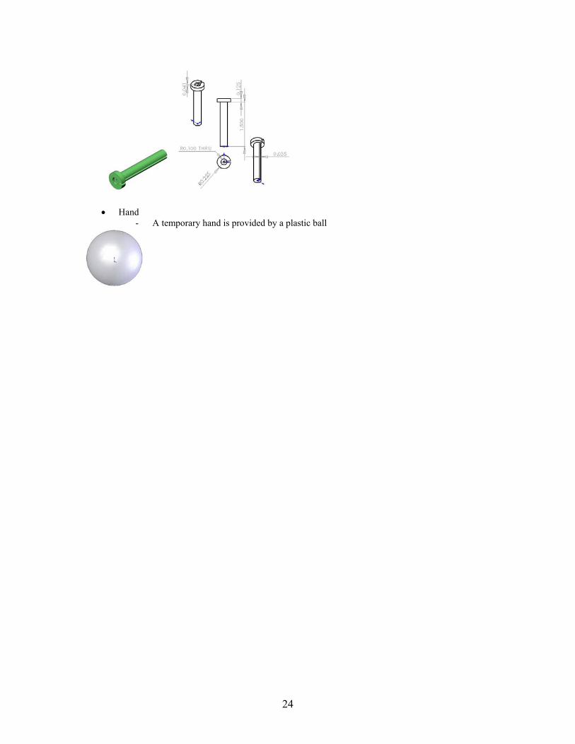
• Spring Box Plate for Part C – springboxplate.sldprt - The spring box plate is milled and is used to tighten the cables by having a screw through
it which adjusts the location of the spring box
• Springs - Two springs are contained inside the spring box and the cables running through the
springs provide the actuation by compressing and extending the springs
• Disk for spring
- The disk for the spring keeps the cable clamp in place and is laser cut out of acrylic
• Cable Clamp cover for spring
- The cable clamp cover holds one of the springs in place and the cable clamp rests inside it as well
24
• Hand
- A temporary hand is provided by a plastic ball

25
Appendix II: Electronics Schematics H-Bridge Schematic (Jamie Rollins)
26
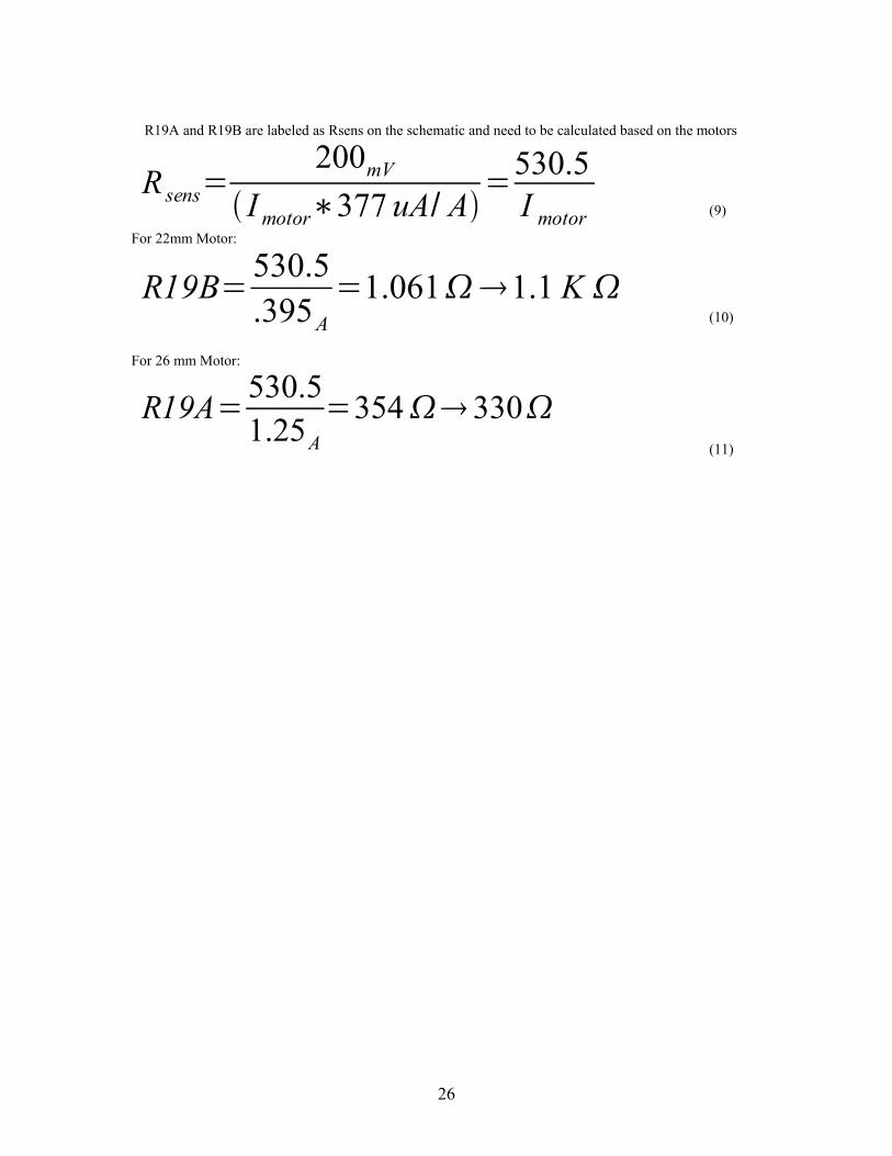
R19A and R19B are labeled as Rsens on the schematic and need to be calculated based on the motors
Rsens
200mV
I motor 377 uA A530.5I motor (9)
For 22mm Motor:
R19B 530.5.395A
1.061 1.1 K (10)
For 26 mm Motor:
R19A 530.51.25A
354 330 (11)

27
DSP Schematic (Eduardo Torres-Jara)

28

29

30

31

32

33

34
Appendix III: Timeline for Completing Tasks Summer 2003
• Worked on electronics and add-on mechanics for the Cardea Segway robot project
Summer 2004
• Researched force actuators specifically other force actuators being used in the humanoid robotics laboratory at MIT
• Accomplished design work including SolidWorks model and engineering calculations
Fall 2004
• Machined parts for two degree-of-freedom robotic arm • Actuators machined and assembled with springs • Parametric segments machined and assembled
Spring 2005
• Mechanical o Completed fabrication and assembly of two degree-of-freedom robotic
arm o Completed cabling for arm o Redesigned components and integrated them into the arm o Used vice to temporarily mount arm and test functionality o Chose springs
• Electrical
o Populated H-bridge and chose appropriate resistors o Populated DSP board and modified JTAG cable o Completed electrical cabling for motors, potentiometers, and power
supplies o Programmed control hardware for robotic arm in C
• Software
o Implementation of a force control loop including demonstration of zero force and off states

35
Contributions by Others Throughout the project, I have had guidance and assistance from several graduate
students in the Humanoid Robotics Laboratory (a division of the Computer Science and Artificial Intelligence Laboratory), particularly Eduardo Torres-Jara, Aaron Edsinger, Lijin Aryananda, and Jessica Banks, who have knowledge in various mechanical, electronic, and software-related aspects of my project. Regina Sullivan also assisted me in making cables and debugging some of the hardware issues and David Lafferty helped me in machining a few of the parts.

36
References
1. Williamson, Matthew. “Series Elastic Actuators.” Master’s thesis. A.I. Technical Report No. 1524. MIT. January 1995
2. Torres-Jara, Eduardo and Jessica Banks. “A Simple and Scalable Force Actuator.” International Simposium of Robotics, 2004.
3. Edsinger-Gonzales, Aaron and Jeff Weber. "Domo: A Force Sensing
Humanoid Robot for Manipulation Research", Proceedings of the IEEE/RSJ International Conference on Humanoid Robotics, 2004.
4. Torres-Jara, Eduardo. http://people.csail.mit.edu/etorresj/robot-obrero/
5. Solidworks Software. Solidworks Corporation. http://www.solidworks.com.
6. CodeWarrior Software. Metrowerks Corporation.
http://www.metrowerks.com.