A Review on Control of a Brushless DC Motor Drive...advantages over brush DC motors and induction...
16
International Journal on Future Revolution in Computer Science & Communication Engineering ISSN: 2454-4248 Volume: 4 Issue: 1 82 – 97 ___________________________________________________________________________________________ 82 IJFRCSCE | January 2018, Available @ http://www.ijfrcsce.org (ICATET 2018) _______________________________________________________________________________________ A Review on Control of a Brushless DC Motor Drive Dr. S. P. Singh 1 , Krishna Kumar Singh 2 Dr. K.S. Verma 3 , Jaswant Singh 4 , and Naveen Tiwari 5 Assistant Professor 1,2 , Kamla Nehru Institute of Technology (KNIT), Sultanpur-228118, U.P., India, Director and Professor 3 , Rajakiya Engineering College, Ambedkar Nagar, UP, India Assistant Professor 4, 5 , Arya College of Engineering & IT (ACEIT), Jaipur-302028 (Raj.), India e-mail- [email protected]; [email protected]; [email protected], [email protected] Abstract— This paper represents the modeling parameters of the Permanent Magnet Brushless DC (PMBLDC) motor drive using Mat-lab / Simulink Software. The modelling of Permanent Magnet Brushless DC (PMBLDC) motor drive is useful in various phenomenon‟s such as aerospace modelling and more other applications. In this Paper, the modelling of PMBLDC motor drive is done by using various components such as current, Speed controllers and sensors are installed to sense the various factors such as speed, current, and the output obtained from the inverter. The basic purpose of designing of such drive is to gives the certain ideas about designing of the motor drive using Mat-lab / Simulink and how it helps in various applications such as electric Traction, automotive industries and more other places. Keywords— PMBLDC, modelling, DC motor P-I Controller & I-P Controller PID Controller Self-tuning fuzzy PID controller. Genetic Algorithm. __________________________________________________*****_________________________________________________ I. INTRODUCTION A brushless DC (BLDC) motor is becoming more popular in sectors such as automotive (particularly electric vehicles (EV)) [8], HVAC, white goods and industrial because it does away with the mechanical commutator used in traditional motors, replacing it with an electronic device such as IGBT and MOSFET that improves the reliability and durability of the motor. Another advantage of a BLDC motor is that it can be made or available in smaller as well as lighter in size than a brush type with the same power output, making the former suitable for applications where small space is needed. The downside is that BLDC motors do need electronic management to run. For example, a microcontroller – using input from hall sensors indicating the position of the rotor for that purpose – it is needed to energize the stator coils at the correct moment. Precise timing allows for accurate speed and torque control, as well as ensuring the motor runs at peak efficiency. This article explains the fundamentals of BLDC motor operation and describes typical control circuit for the operation of a three-phase unit [1] - [2]. The article also considers some of the integrated modules – that the designer can select to ease the circuit design – which are specifically designed for BLDC motor control. The Permanent magnet brushless motors are categorized into two kinds depending upon the back EMF waveform, Brushless AC (PMBLAC) and Permanent Magnet Brushless DC (PMBLDC) motors. PMBLDC motors have trapezoidal back EMF and quasi-rectangular current waveform. PMBLDC motors are quickly becoming famous in industries like HVAC industry [44 - [48]], military equipment, medical Appliances, electric traction, automotive, aircrafts, disk drive, industrial drives and instrumentation because of their high efficiency, silent operation, high power factor, reliability, compact, low maintenance and high power density The brushes of a conventional motor transmit power to the rotor windings which, when energized, turn in a fixed magnetic field [53] - [54] - [68] - [71] - [72] . Friction between the stationary brushes and a rotating metal contact on the spinning rotor causes wear. In addition, power can be lost due to poor brush to metal contact and arcing [79] - [80] - [82] - [83] - [85] - [86] - [87]. Because a BLDC motor dispenses with the brushes – instead employing an “electronic commutator” the motor‟s reliability and efficiency is improved by eliminating this source of wear and power loss. In addition, BLDC motors boast a number of other advantages over brush DC motors and induction motors, including better speed versus torque characteristics; faster dynamic response; noiseless operation; and higher speed ranges [121]. Moreover, the ratio of torque delivered relative to the motor‟s size is higher, making it a good choice for applications such as washing machines and EVs, where high power is needed but compactness and lightness are critical factors While some of the new achievements of modern control theory, including pole placement and optimal control linear regulator based on precise feedback linearization, model reference adaptive control, are used to the control technology of motor to effectively improve the performance of brushless DC motor [3] - [4] - [5] - [6]. But modern control theory is still dependent on the precise mathematical model of the motor, the motor performance parameters changes are impacted vulnerability by various uncertainties. A BLDC motor is known as a “synchronous” type because the magnetic field generated by the stator and the rotor revolve at the same frequency. One benefit of this arrangement is that BLDC motors do not experience the “slip” typical of i nduction motors. II. CONSTRUCTION AND OPERATING PRINCIPLE Unlike any other rotating electrical machine BLDC motor have also the similar construction and operating principle. It has two main elements the first one is rotor and the second one is stator. The other important parts are stator winding and permanent magnet which is mounted on the stator and rotor respectively. Permanent magnets are also called as rotor magnet. [43] - [45]. Rotor- The brushless DC motor have two basic design constraints for rotor, The first one is inner rotor design and the
Transcript of A Review on Control of a Brushless DC Motor Drive...advantages over brush DC motors and induction...

International Journal on Future Revolution in Computer Science & Communication Engineering ISSN: 2454-4248 Volume: 4 Issue: 1 82 – 97
___________________________________________________________________________________________
82
IJFRCSCE | January 2018, Available @ http://www.ijfrcsce.org (ICATET 2018)
_______________________________________________________________________________________
A Review on Control of a Brushless DC Motor Drive
Dr. S. P. Singh1, Krishna Kumar Singh
2 Dr. K.S. Verma
3, Jaswant Singh
4, and Naveen Tiwari
5
Assistant Professor1,2
, Kamla Nehru Institute of Technology (KNIT), Sultanpur-228118, U.P., India,
Director and Professor 3, Rajakiya Engineering College, Ambedkar Nagar, UP, India
Assistant Professor4, 5
, Arya College of Engineering & IT (ACEIT), Jaipur-302028 (Raj.), India
e-mail- [email protected]; [email protected]; [email protected], [email protected]
Abstract— This paper represents the modeling parameters of the Permanent Magnet Brushless DC (PMBLDC) motor drive using Mat-lab /
Simulink Software. The modelling of Permanent Magnet Brushless DC (PMBLDC) motor drive is useful in various phenomenon‟s such as
aerospace modelling and more other applications. In this Paper, the modelling of PMBLDC motor drive is done by using various components
such as current, Speed controllers and sensors are installed to sense the various factors such as speed, current, and the output obtained from the
inverter. The basic purpose of designing of such drive is to gives the certain ideas about designing of the motor drive using Mat-lab / Simulink
and how it helps in various applications such as electric Traction, automotive industries and more other places.
Keywords— PMBLDC, modelling, DC motor P-I Controller & I-P Controller PID Controller Self-tuning fuzzy PID controller. Genetic
Algorithm.
__________________________________________________*****_________________________________________________
I. INTRODUCTION
A brushless DC (BLDC) motor is becoming more popular in
sectors such as automotive (particularly electric vehicles (EV))
[8], HVAC, white goods and industrial because it does away
with the mechanical commutator used in traditional motors,
replacing it with an electronic device such as IGBT and
MOSFET that improves the reliability and durability of the
motor. Another advantage of a BLDC motor is that it can be
made or available in smaller as well as lighter in size than a
brush type with the same power output, making the former
suitable for applications where small space is needed. The
downside is that BLDC motors do need electronic
management to run. For example, a microcontroller – using
input from hall sensors indicating the position of the rotor for
that purpose – it is needed to energize the stator coils at the
correct moment. Precise timing allows for accurate speed and
torque control, as well as ensuring the motor runs at peak
efficiency. This article explains the fundamentals of BLDC
motor operation and describes typical control circuit for the
operation of a three-phase unit [1] - [2]. The article also
considers some of the integrated modules – that the designer
can select to ease the circuit design – which are specifically
designed for BLDC motor control.
The Permanent magnet brushless motors are categorized
into two kinds depending upon the back EMF waveform,
Brushless AC (PMBLAC) and Permanent Magnet Brushless
DC (PMBLDC) motors. PMBLDC motors have trapezoidal
back EMF and quasi-rectangular current waveform. PMBLDC
motors are quickly becoming famous in industries like HVAC
industry [44 - [48]], military equipment, medical Appliances,
electric traction, automotive, aircrafts, disk drive, industrial
drives and instrumentation because of their high efficiency,
silent operation, high power factor, reliability, compact, low
maintenance and high power density The brushes of a
conventional motor transmit power to the rotor windings
which, when energized, turn in a fixed magnetic field [53] -
[54] - [68] - [71] - [72] . Friction between the stationary
brushes and a rotating metal contact on the spinning rotor
causes wear. In addition, power can be lost due to poor brush
to metal contact and arcing [79] - [80] - [82] - [83] - [85] - [86]
- [87]. Because a BLDC motor dispenses with the brushes –
instead employing an “electronic commutator” the motor‟s
reliability and efficiency is improved by eliminating this
source of wear and power loss.
In addition, BLDC motors boast a number of other
advantages over brush DC motors and induction motors,
including better speed versus torque characteristics; faster
dynamic response; noiseless operation; and higher speed
ranges [121]. Moreover, the ratio of torque delivered relative
to the motor‟s size is higher, making it a good choice for
applications such as washing machines and EVs, where high
power is needed but compactness and lightness are critical
factors While some of the new achievements of modern
control theory, including pole placement and optimal control
linear regulator based on precise feedback linearization, model
reference adaptive control, are used to the control technology
of motor to effectively improve the performance of brushless
DC motor [3] - [4] - [5] - [6]. But modern control theory is still
dependent on the precise mathematical model of the motor, the
motor performance parameters changes are impacted
vulnerability by various uncertainties. A BLDC motor is
known as a “synchronous” type because the magnetic field
generated by the stator and the rotor revolve at the same
frequency. One benefit of this arrangement is that BLDC
motors do not experience the “slip” typical of induction
motors.
II. CONSTRUCTION AND OPERATING PRINCIPLE
Unlike any other rotating electrical machine BLDC
motor have also the similar construction and operating
principle. It has two main elements the first one is rotor and
the second one is stator. The other important parts are stator
winding and permanent magnet which is mounted on the stator
and rotor respectively. Permanent magnets are also called as
rotor magnet. [43] - [45].
Rotor- The brushless DC motor have two basic design
constraints for rotor, The first one is inner rotor design and the

International Journal on Future Revolution in Computer Science & Communication Engineering ISSN: 2454-4248 Volume: 4 Issue: 1 82 – 97
___________________________________________________________________________________________
83
IJFRCSCE | January 2018, Available @ http://www.ijfrcsce.org (ICATET 2018)
_______________________________________________________________________________________
second one is outer rotor design. In case of inner rotor design
the rotor magnets are surrounded by the stator winding and are
fixed into the housing of the motor. One of most advantageous
point for the inner rotor construction is its ability to dissipate
heat which is generated inside the stator winding. Due to the
proper heat dissipation property this type of motor able to
produce more torque. For this reason, the majority of BLDC
motor are of inner rotor design type. [101] - [102]. The other
one is outer rotor design in this type of construction the stator
winding are placed in the core of the motor and the rotor
magnet surrounds the stator winding. The rotor magnet works
as an insulator between the stator winding and the yoke of the
machine hence heat generated inside the stator winding is not
dissipated homogeneously throughout the motor. Due to the
location of stator winding the outer rotor design of BLDC
motor operates on low voltage and current. Means its rated
voltage and rated current are lower as compared to the similar
rating of inner rotor design BLDC motor. The primary
advantage of this type of rotor is its relatively low cogging
torque.
Fig.1 Inner rotor and outer rotor design
The stator of a permanent magnet brushless DC motor
comprises of stacked steel laminations with windings kept in
the slots that are cut along the inner periphery. Most of the
permanent magnet brushless DC motors have three stator
windings linked in star. Each of these windings is assembled
along with various coils interconnected to derive a winding.
One or more than one coils are kept in the slots and they are
interconnected to form a winding. Each of these windings is
distributed over the stator peripheral area to form an even
numbers of poles. The stator winding wound either in clock
wise or in counter clock wise direction to along with each arm
of the stator to produce magnetic poles. The primary
difference between AC and DC motor is the applied power to
the armature. From this point of view, a BLDC motor actually
is an AC motor. [106] - [145]. The BLDC motor converts
electrical energy into mechanical energy using electromagnetic
principles. The energy conversion method is fundamentally the
same in all electric motor. Motor operation is based on the
attraction or repulsion between magnetic poles. In three phase
motor the process start when current flows through one of the
three stator winding generates a magnetic pole that attracts the
closest permanent magnet of the opposite pole. The rotor will
move if the current shift to an adjacent winding. Sequentially
charging of each winding will cause the rotor to follow the
rotating field.
Fig. 2 Rotor and Hall sensors of PMBLDC motor
III. ADVANTAGES OF BLDC MOTOR OVER OTHER
MOTORS
In this section we are going to made the comparison
of different parameters of brushless DC motor with induction
motor as well as brushed DC motor. Due to the advantages
mentioned below the brushless DC motor are most widely
accepted motor for industrial as well as commercial
application over the other type of motor having the similar
rating. On the basis of highlighted advantages, the brushless
DC motor having the capability to replace the other type of
motor and owing to its wide range of application.
Table I
Comparison of BLDC Motor with Brushed DC and
Induction Motor
Advatages Brushless
DC motor
Brushed DC
motor
Induction
motor
Mechanical
Structure
Field Winding
on stator and
permanent
magnets on
rotor.
Field Winding
on the rotor and
stator are made
of permanent
magnets or
electromagnet
Both the rotor
and stator
have
windings but
the AC lines
are connected
to the stator
Maintenance No
maintenance
Periodic
maintenance
because of
brushes
Low
maintenance
Speed-
Torque
characteristic
Flat –
operation at
all speeds
with rated
load
Moderate – Loss
in torque at
higher speeds
because of
losses in brushes
Non-linear
Efficiency High
Moderate
High
efficiency
Commutatio
n method
Using solid
state
switches
Mechanical
contacts
between
brushes and
commutator
Special
starting
circuit is
required
International Journal on Future Revolution in Computer Science & Communication Engineering ISSN: 2454-4248 Volume: 4 Issue: 1 82 – 97
___________________________________________________________________________________________
84
IJFRCSCE | January 2018, Available @ http://www.ijfrcsce.org (ICATET 2018)
_______________________________________________________________________________________
Speed
Range
High - no
losses in
brushes
Moderate –
losses in
brushes
Low
determined
by the AC
line
frequency;
increases in
load
further
reduces speed
Detecting
method of
rotors
position
Hall sensors,
optical
encoders, etc.
Automatically
detected by
brushes and
commutator
NA
Direction
reversal
Reversing
the switching
sequence
Reversing the
terminal
voltage
By
changing
the two
phases of
the motor
input
Electrical
noise Low
High – as
brushes used Low
System
cost
High-because
Of external
Controller
requirement
Low Low
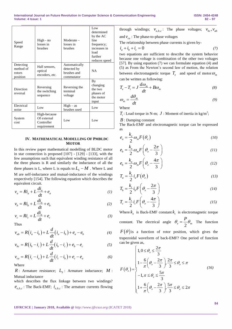
IV. MATHEMATICAL MODELLING OF PMBLDC
MOTOR
In this review paper mathematical modelling of BLDC motor
in star connection is proposed [107] - [129] - [133], with the
few assumptions such that equivalent winding resistance of all
the three phases is R and similarly the inductance of all the
three phases is L, where L is equals to SL M . Where L and
M are self-inductance and mutual-inductance of the windings
respectively [154]. The following equation which describes the
equivalent circuit.
aa a a
div Ri L e
dt (1)
ab b b
div Ri L e
dt (2)
ac c c
div Ri L e
dt (3)
Thus
ab a b a b a b
dv R i i L i i e e
dt (4)
bc b c b c b c
dv R i i L i i e e
dt (5)
ca c a c b c a
dv R i i L i i e e
dt (6)
Where
R : Armature resistance; SL : Armature inductance; M :
Mutual inductance
which describes the flux linkage between two windings?
, ,a b ce : The Back-EMF; , ,a b ci : The armature currents flowing
through windings; , ,a b cv : The phase voltages; ,bc abv v
and cav : The phase-to-phase voltages
The relationship between phase currents is given by-
0a b ci i i (7)
two equations are sufficient to describe the system behavior
because one voltage is combination of the other two voltages
[57]. By using equation (7) we can formulate equation (4) and
(5) as From the Newton‟s second law of motion, the relation
between electromagnetic torque eT and speed of motor m
can be written as following:
me i m
dT T J B
dt
(8)
mm
d
dt
(9)
Where
iT : Load torque in N-m; J : Moment of inertia in kg/m2;
B : Damping constant
The Back-EMF and electromagnetic torque can be expressed
as
2
ea m e
ke F (10)
2
2 3
eb m e
ke F
(11)
4
2 3
eb m e
ke F
(12)
2
ta a e
kT i F (13)
2
2 3
tb b e
kT i F
(14)
4
2 3
tc c e
kT i F
(15)
Where ek is Back-EMF constant tk is electromagnetic torque
constant. The electrical angle 2
e m
P The function
F is a function of rotor position, which gives the
trapezoidal waveform of back-EMF? One period of function
can be given as,
21,0
3
6 2 21 ,
3 3
51,
3
6 2 51 , 2
3 3
e
e e
e
e
e e
F
(16)

International Journal on Future Revolution in Computer Science & Communication Engineering ISSN: 2454-4248 Volume: 4 Issue: 1 82 – 97
___________________________________________________________________________________________
85
IJFRCSCE | January 2018, Available @ http://www.ijfrcsce.org (ICATET 2018)
_______________________________________________________________________________________
Due to the symmetry design of motor, the Back-EMF signal of
each phase is 120 degrees‟ phase shifted with respect to each
other as shown in figure 3. Shows the Back EMF and current
in each phase.
Fig. 3 Desire Waveforms of Three Phase BLDC Motor
V.CONVERTER TOPOLOGY USED FOR BLDC MOTOR
DRIVE
Electronic commutation is used to control BLDC motors; it
makes the drive costlier when comparing with other electric
motors. Conventionally for a three phase BLDC motor six
switches are used to drive the motor [16] - [17], as shown in
Fig.3 Nowadays many studies are focusing on how to reduce
the cost of BLDC motor drive [49]- [50] - [51] - [89] - [90] -
[91]. Four switch topology is a way to reduce the cost of three
phase BLDC drive; where it reduces the number of switch by
two [6], as shown in Fig.4. The main drawback of the four
switch topology is speed limitation of BLDC motor. A
conventional four switch BLDC drive can operate only up to
half of the rated speed. By combining two input dc-dc boost
converter with four switch BLDC drive topology, a low cost
three phase BLDC drive can be formed for hybrid electric
vehicle [100] - [103]. Two input dc-dc boost converter is used
to supply the voltage to four switch converter. By regulating
the output voltage of two input dc BLDC motor; the motor can
run up to rated speed.
Fig.4 Conventional six-switch converter topology
Fig.5 Four-switch converter topology
In four switch topology, four switches are used instead of six
and one phase is directly connected to the common point of
dc-dc capacitor [60]. The topology is shown in fig. 4.the
desired back-emf and current profile are shown in fig. 3. In the
case of the BLDC motor drive, for every mode one phase
current will be zero.
VI. BLDC MOTOR WITH COLSED LOOP MODEL
The Brushless DC motor drive system consists of permanent
magnet synchronous motor fed by a three-phase voltage source
inverter [52] - [55] - [56] - [92]. Fig. 6 shows the overall
closed loop system configuration of three phase BLDC motor
drive as we know that the open loop system is more stable than
close loop system hence for making the close loop BLDC
drive more stable as per the desired application the different
type of controller along with the converter topology are used.
The inner loop of the drive consists hall effect sensor which is
used to provide the information about the rotor position of the
BLDC drive based on that information the Gate signal
generator generates the commutating signals for three phase
VSI. The triggering pulse is nothing but the back EMF of the
motor which is coming from the particular position of the
rotor. Gate signal generator includes the back EMF generator
and gate logic decoder and the combined effect of these two
signal along with the reference signal generates the triggering
pulses.
Fig. 6 Block diagram of closed loop model PMBLDC drive.
VII. CONTROL SCHEME FOR BLDC MOTOR DRIVE
Brushless DC motor known as permanent magnet synchronous
motor or may be described as electronically commuted motor
which do not have brushes, which means their rotor and stator
runs at same frequency that are powered with direct current
(DC) inverter/switching power supply, which is build up by
using a universal bridge [78].
The configuration of BLDC motor controller consists of
power converter in which three phase VSI work as a brushes
of BLDC motor and to operate the VSI power are fed to VSI
with different type of converters like Bidirectional converter,
International Journal on Future Revolution in Computer Science & Communication Engineering ISSN: 2454-4248 Volume: 4 Issue: 1 82 – 97
___________________________________________________________________________________________
86
IJFRCSCE | January 2018, Available @ http://www.ijfrcsce.org (ICATET 2018)
_______________________________________________________________________________________
CUCK converters, SEPIC converters etc. these converters
handles the power and power factor requirement of the drive.
Along with the converters the drive system consists of the
PMSM, hall sensor and different type of control algorithms.
[99] - [109] - [114]. Three phase VSI transforms power mains
to the PMSM which in turn converts electrical energy into
mechanical energy. BLDC motor has rotor position sensors
controlled by the command signals, the different command
signal used in BLDC drive are torque, voltage, speed, current
and so on. The type of BLDC drive is determined by the
structure of control algorithms based on that algorithms two
main type of drive are becoming more popular which is
nothing but voltage source and current source based drive
[115] - [118] - [155]. Permanent magnet synchronous machine
with either sinusoidal or trapezoidal back-EMF waveforms is
used by both voltage source and current source based drive
[43].
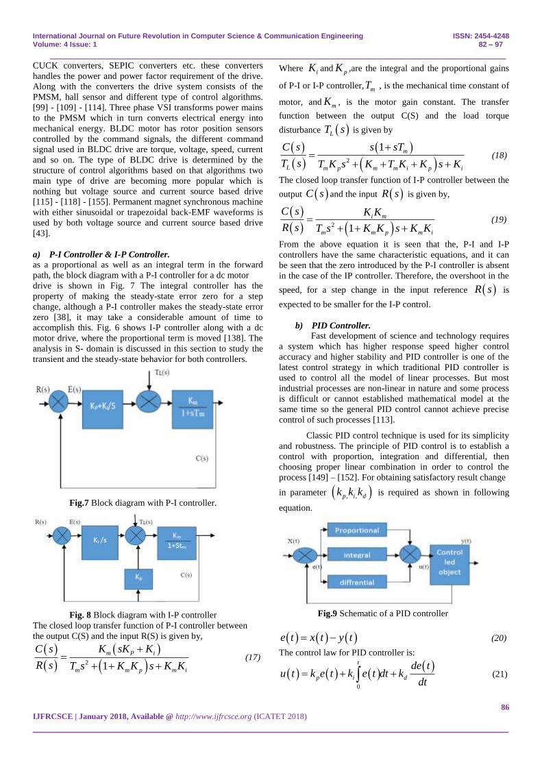
a) P-I Controller & I-P Controller.
as a proportional as well as an integral term in the forward
path, the block diagram with a P-I controller for a dc motor
drive is shown in Fig. 7 The integral controller has the
property of making the steady-state error zero for a step
change, although a P-I controller makes the steady-state error
zero [38], it may take a considerable amount of time to
accomplish this. Fig. 6 shows I-P controller along with a dc
motor drive, where the proportional term is moved [138]. The
analysis in S- domain is discussed in this section to study the
transient and the steady-state behavior for both controllers.
Fig.7 Block diagram with P-I controller.
Fig. 8 Block diagram with I-P controller
The closed loop transfer function of P-I controller between
the output C(S) and the input R(S) is given by,
2 1
m P i
m m p m i
C s K sK K
R s T s K K s K K
(17)
Where iK and
pK ,are the integral and the proportional gains
of P-I or I-P controller, mT , is the mechanical time constant of
motor, and mK , is the motor gain constant. The transfer
function between the output C(S) and the load torque
disturbance LT s is given by
2
1 m
L m p m m i p i
C s s sT
T s T K s K T K K s K
(18)
The closed loop transfer function of I-P controller between the
output C s and the input R s is given by,
2 1
i m
m m p m i
C s K K
R s T s K K s K K
(19)
From the above equation it is seen that the, P-I and I-P
controllers have the same characteristic equations, and it can
be seen that the zero introduced by the P-I controller is absent
in the case of the IP controller. Therefore, the overshoot in the
speed, for a step change in the input reference R s is
expected to be smaller for the I-P control.
b) PID Controller.
Fast development of science and technology requires
a system which has higher response speed higher control
accuracy and higher stability and PID controller is one of the
latest control strategy in which traditional PID controller is
used to control all the model of linear processes. But most
industrial processes are non-linear in nature and some process
is difficult or cannot established mathematical model at the
same time so the general PID control cannot achieve precise
control of such processes [113].
Classic PID control technique is used for its simplicity
and robustness. The principle of PID control is to establish a
control with proportion, integration and differential, then
choosing proper linear combination in order to control the
process [149] – [152]. For obtaining satisfactory result change
in parameter , ,p i dk k k is required as shown in following
equation.
Fig.9 Schematic of a PID controller
e t x t y t (20)
The control law for PID controller is:
0
t
p i d
de tu t k e t k e t dt k
dt (21)
International Journal on Future Revolution in Computer Science & Communication Engineering ISSN: 2454-4248 Volume: 4 Issue: 1 82 – 97
___________________________________________________________________________________________
87
IJFRCSCE | January 2018, Available @ http://www.ijfrcsce.org (ICATET 2018)
_______________________________________________________________________________________
Where pk is proportion gain coefficient,
ik is integration
time coefficient, dk is differential time coefficient.
Proportion part-: proportional link in PID controller is
used to reflect the deviated signal. If deviation is
present, then it can reduce the deviation of the signal
from the original one.
Integral part-: the integral part is used to minimizes or
to eliminates the steady state error and also improves
the steady state stability of the system.
Differential part-: can reflect the change trend of
deviation signal (change rate), and before the value of
the deviation signal become too large, the system
introduced in an effective early correction signal, speed
up the action of the system, reduce the adjusting time.
The problem in the PID controller is to choose the three
parameters to be suitable for the controlled plant. There are
many methods to define the parameters of PID controller such
as try and error, Ziegler-Nichols methods and three different
cost function genetic algorithm techniques.
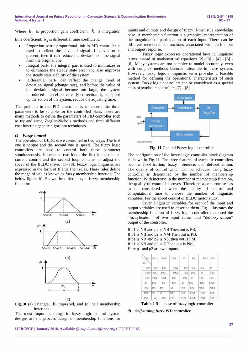
c) Fuzzy control
The operation of BLDC drive controlled in two ways, The first
one is torque and the second one is speed. The fuzzy logic
controllers are used to control both these parameter
simultaneously. It contains two loops the first loop contains
current control and the second loop contains or adjust the
speed of the BLDC drive. [1]- [8]. Fuzzy logic linguistic are
expressed in the form of If and Then rules. These rules define
the range of values known as fuzzy membership function. The
below figure 10, Shows the different type fuzzy membership
functions.
(a)
(b)
(c)
Fig.10 (a) Triangle, (b) trapezoid, and (c) bell membership
functions
The most important things in fuzzy logic control system
designs are the process design of membership functions for
inputs and outputs and design of fuzzy if-then rule knowledge
base. A membership function is a graphical representation of
the magnitude of participation of each input. There can be
different memberships functions associated with each input
and output response.
Fuzzy logic expresses operational laws in linguistic
terms instead of mathematical equations [2]- [3] - [4] - [5] -
[6]. Many systems are too complex to model accurately, even
with complex methods become infeasible in these system.
However, fuzzy logic‟s linguistic term provides a feasible
method for defining the operational characteristics of such
system. Fuzzy logic controllers can be considered as a special
class of symbolic controllers [7] - [8].
Fig. 11 General Fuzzy logic controller
The configuration of the fuzzy logic controller block diagram
is shown in Fig.11. The three features of symbolic controllers
become fuzzification, fuzzy inference, and defuzzification.
The quality of control which can be achieved using fuzzy
controller is determined by the number of membership
function. With increase in the number of membership function,
the quality of control improves. Therefore, a compromise has
to be considered between the quality of control and
computational time to choose the number of linguistic
variables. For the speed control of BLDC motor study.
Seven linguistic variables for each of the input and
output variables are used to describe them. Fig. illustrates the
membership function of fuzzy logic controller that used the
“fuzzyfication” of two input values and “defuzzyfication”
output of the controller.
If p1 is NB and p2 is NB Then out is PB,
If p1 is NB and p2 is NM Then out is PB,
If p1 is NB and p2 is NS, then out is PM,
If p1 is NB and p2 is Z Then out is PM,
Here p1 and p2 are two inputs.
Table.2 Rule base of fuzzy logic controller
d) Self-tuning fuzzy PID controller.

International Journal on Future Revolution in Computer Science & Communication Engineering ISSN: 2454-4248 Volume: 4 Issue: 1 82 – 97
___________________________________________________________________________________________
88
IJFRCSCE | January 2018, Available @ http://www.ijfrcsce.org (ICATET 2018)
_______________________________________________________________________________________
Although Ziegler and Nichols proposed an efficient technique
to tune the coefficients of a PID Controller and improve the
performance by optimizing the PID parameters using different
optimization techniques but cannot guarantee to be always
effective, So self-tuning of PID controller is required [36] -
[37 - [39] - [40] - [41] - [42] - [46], and this fuzzy-PID
controller fulfill the need. The controller includes two parts:
conventional PID controller and fuzzy logic control (FLC)
part, which has self-tuning. Now the control action of the PID
controller after self-tuning can be describing as: Fuzzy self-
tuning PID controller with error e and error change rate ec as
input, PID parameter , ,p i dk k k as output e and ec can
satisfy the self-tuning of the PID parameters. Using the fuzzy
control rules to modify the PID parameters online, where we
constitute a fuzzy self-tuning PID controller [136] - [137] -
[139]. Where e is error and ec is error change rate, so ek and
eck quantitative factors, uk is the scaling factor from all
aspects of stability, response speed, overshoot, and steady-
state error of the system and other considerations, PID
controller three parameters , ,p i dk k k role as follows [141]:
The proportional coefficient Kp is to accelerate the
response speed of the system and improve the regulation
accuracy of the system. However, the more easily Kp
larger system overshoot, or even make the system
unstable. Kp Value is too small. It will reduce the
regulation accuracy, so that slow down the response,
thereby extending the regulation time, static and dynamic
characteristics of the system deteriorates.
Differential coefficient Kd is to improve the dynamic
characteristics of the system, mainly inhibit change
deviation in any direction in response to the process, in
advance of the forecast error. But Kd too large, it will
advance the process of brake response, thereby extending
the regulation time, reduce anti-jamming performance of
the system.
Fig. 12 Block diagram of Fuzzy self-tuning PID control
system.
e) Genetic Algorithm
Genetic algorithms are a type of optimization algorithm,
meaning they are used to find the optimal solution(s) to a
given computational problem that maximizes or minimizes a
particular function. Genetic algorithms represent one branch of
the field of study called evolutionary computation [54], in that
they imitate the biological processes of reproduction and
natural selection to solve for the „fittest‟ solutions [58]. Like in
evolution, many of a genetic algorithm‟s processes are
random, however this optimization technique allows one to set
the level of randomization and the level of control [98]. These
algorithms are far more powerful and efficient than random
search and exhaustive search algorithms [114], yet require no
extra information about the given problem. This feature allows
them to find solutions to problems that other optimization
methods cannot handle due to a lack of continuity, derivatives,
linearity, or other features.
i. Encoding
Individual binary string consists of three coefficient gain
parameter of PID controller Kp, Ki and Kd is used to ensure
that the variables are independent. Unsigned binary coding is
applied for encoding [22].
ii. Initialization
The first population is generated at random within the
boundaries. The boundaries for PID controller constant have
been chosen such that not too many PID controller constants
leading system to be unstable
iii. Objective Function
An essential step for GA is choosing objective function,
which is used to evaluate the fitness of each chromosome. For
the design of a GA-PID controller we use integral of the
squared error (ISE).
iv. Fitness Function
The fitness function is the function that the algorithm is trying
to optimize [65]. The word “fitness” is taken from
evolutionary theory. It is used here because the fitness function
tests and quantifies how „fit‟ each potential solution is. The
fitness function is one of the most pivotal parts of the
algorithm, so it is discussed in more detail at the end of this
section. The term chromosome refers to a numerical value or
values that represent a candidate solution to the problem that
the genetic algorithm is trying to solve [23], [24].
The fitness value concluded as Fitness
value=1/performance index (6) In order to overcome the large
energy of controller, we add square term of controller output
u(t). Thus fitness function is defined as follows:
2
1 2 3
0
( ( ) ( ) ( ) rJ Ie t u t d t t
(22)
v. Selection
In our problem design, standard roulette wheel
selection has been applied to select individual from the current
pool of population. The offspring are produced based on the
selection value. The selection value depends on the fitness
value of individual, bigger the fitness value more offspring the
individual produce [25].
f) Neural Network Controller.
International Journal on Future Revolution in Computer Science & Communication Engineering ISSN: 2454-4248 Volume: 4 Issue: 1 82 – 97
___________________________________________________________________________________________
89
IJFRCSCE | January 2018, Available @ http://www.ijfrcsce.org (ICATET 2018)
_______________________________________________________________________________________
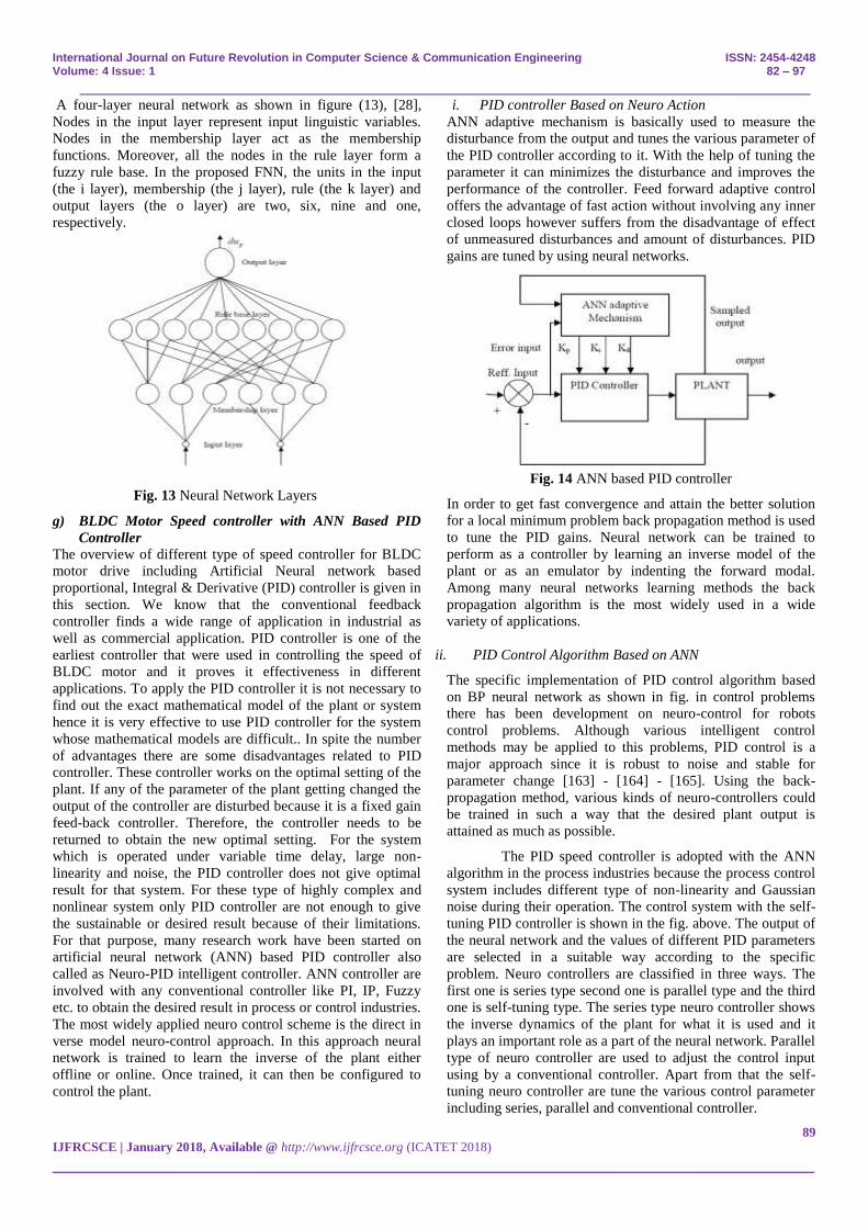
A four-layer neural network as shown in figure (13), [28],
Nodes in the input layer represent input linguistic variables.
Nodes in the membership layer act as the membership
functions. Moreover, all the nodes in the rule layer form a
fuzzy rule base. In the proposed FNN, the units in the input
(the i layer), membership (the j layer), rule (the k layer) and
output layers (the o layer) are two, six, nine and one,
respectively.
Fig. 13 Neural Network Layers
g) BLDC Motor Speed controller with ANN Based PID
Controller
The overview of different type of speed controller for BLDC
motor drive including Artificial Neural network based
proportional, Integral & Derivative (PID) controller is given in
this section. We know that the conventional feedback
controller finds a wide range of application in industrial as
well as commercial application. PID controller is one of the
earliest controller that were used in controlling the speed of
BLDC motor and it proves it effectiveness in different
applications. To apply the PID controller it is not necessary to
find out the exact mathematical model of the plant or system
hence it is very effective to use PID controller for the system
whose mathematical models are difficult.. In spite the number
of advantages there are some disadvantages related to PID
controller. These controller works on the optimal setting of the
plant. If any of the parameter of the plant getting changed the
output of the controller are disturbed because it is a fixed gain
feed-back controller. Therefore, the controller needs to be
returned to obtain the new optimal setting. For the system
which is operated under variable time delay, large non-
linearity and noise, the PID controller does not give optimal
result for that system. For these type of highly complex and
nonlinear system only PID controller are not enough to give
the sustainable or desired result because of their limitations.
For that purpose, many research work have been started on
artificial neural network (ANN) based PID controller also
called as Neuro-PID intelligent controller. ANN controller are
involved with any conventional controller like PI, IP, Fuzzy
etc. to obtain the desired result in process or control industries.
The most widely applied neuro control scheme is the direct in
verse model neuro-control approach. In this approach neural
network is trained to learn the inverse of the plant either
offline or online. Once trained, it can then be configured to
control the plant.
i. PID controller Based on Neuro Action
ANN adaptive mechanism is basically used to measure the
disturbance from the output and tunes the various parameter of
the PID controller according to it. With the help of tuning the
parameter it can minimizes the disturbance and improves the
performance of the controller. Feed forward adaptive control
offers the advantage of fast action without involving any inner
closed loops however suffers from the disadvantage of effect
of unmeasured disturbances and amount of disturbances. PID
gains are tuned by using neural networks.
Fig. 14 ANN based PID controller
In order to get fast convergence and attain the better solution
for a local minimum problem back propagation method is used
to tune the PID gains. Neural network can be trained to
perform as a controller by learning an inverse model of the
plant or as an emulator by indenting the forward modal.
Among many neural networks learning methods the back
propagation algorithm is the most widely used in a wide
variety of applications.
ii. PID Control Algorithm Based on ANN
The specific implementation of PID control algorithm based
on BP neural network as shown in fig. in control problems
there has been development on neuro-control for robots
control problems. Although various intelligent control
methods may be applied to this problems, PID control is a
major approach since it is robust to noise and stable for
parameter change [163] - [164] - [165]. Using the back-
propagation method, various kinds of neuro-controllers could
be trained in such a way that the desired plant output is
attained as much as possible.
The PID speed controller is adopted with the ANN
algorithm in the process industries because the process control
system includes different type of non-linearity and Gaussian
noise during their operation. The control system with the self-
tuning PID controller is shown in the fig. above. The output of
the neural network and the values of different PID parameters
are selected in a suitable way according to the specific
problem. Neuro controllers are classified in three ways. The
first one is series type second one is parallel type and the third
one is self-tuning type. The series type neuro controller shows
the inverse dynamics of the plant for what it is used and it
plays an important role as a part of the neural network. Parallel
type of neuro controller are used to adjust the control input
using by a conventional controller. Apart from that the self-
tuning neuro controller are tune the various control parameter
including series, parallel and conventional controller.

International Journal on Future Revolution in Computer Science & Communication Engineering ISSN: 2454-4248 Volume: 4 Issue: 1 82 – 97
___________________________________________________________________________________________
90
IJFRCSCE | January 2018, Available @ http://www.ijfrcsce.org (ICATET 2018)
_______________________________________________________________________________________
Fig.15 PID control algorithm based on Artificial-Neural
Network
VIII. ANALYSIS OF DIFFERENT SPEED CONTROLLERS
The performance analysis of same rating of BLDC motor with
different type of speed controllers on no load are specified in
the below table. On the basis of different parameter like rise
time, settling time, peak overshoot, steady state error, torque
ripple, speed ripple etc. With the help of these parameters we
can conclude the relative stability or performance of BLDC
motor the parameters which is mentioned here are varies due
to different type of loading like step loading continuous
loading periodic loading etc.
These parameters are also rating dependent means if
the rating of motor and reference speed are changed these
parameters are changed.
Table 3. Performance Comparision of Different Speed
Controllers
CONT
ROLL
ER
SPECIFICATIONS
SETTLING
TIME
OVER
SHOOT RISE TIME
PI Increase Increase Decrease
PID Decrease
Decrease as
compared to
PI
Increase as
compared to
PI
FUZZY
Decrease as
compared to
PID
Decrease as
compared to
PID
Increase as
compared to
PID
FUZZY
+
PID
Decrease as
compared to
FUZZY
Decrease as
compared to
FUZZY
Increase as
compared to
FUZZY
IX. CONCLUSION
It was concluded in this paper that the different types of
converter are used for the supply of BLDC motor drive as per
application like bidirectional converter for vehicle application,
power factor correction CUCK or SEPIC converter. These
converters are known as conventional converter which is used
with constant DC link voltage of the VSI. The speed of the
motor is controlled by controlling the duty ratio of high
frequency pulse width modulation (PWM) single. Different
type of speed controllers is also used for controlling the drive
speed at desired value. Like PI, IP, PID, FUZZY, etc. These
controllers are used according to the application needed. It was
shown that PI controller maintain the steady state accuracy.
Means the application where we need minimum error the PI
controller is used. The IP controller has integrated both fuzzy
and PI controller. During the large speed error, the fuzzy
controller is selected by switch and PI controller are selected
when high steady state accuracy is needed.
References
[1] Dilip kumar, R. A. gupta, Nitin Gupta “Minimization of current
ripple and overshoot in four switch three phase inverter fed
BLDC motor using tracking anti windup PI controller,” 2017
IEEE International Conference on Signal Processing,
International Journal on Future Revolution in Computer Science & Communication Engineering ISSN: 2454-4248 Volume: 4 Issue: 1 82 – 97
___________________________________________________________________________________________
91
IJFRCSCE | January 2018, Available @ http://www.ijfrcsce.org (ICATET 2018)
_______________________________________________________________________________________
Informatics, Communication and Energy Systems (SPICES)
pages 1-6.
[2] Sonu Jayachandran, Pavana, U. Vinatha “One cycle control
bridge-less SEPIC Converter Fed BLDC motor Drive,” 2017
IEEE International Conference on Signal Processing,
Informatics, Communication and Energy Systems (SPICES)
pages 1-6.
[3] Kota Chandrika Naga Sridivya; T. Vamsee Kiran, “Space
Vector PWM Control of BLDC motor Drive,” 2017
International Conference on Power and Embedded Drive
Control (ICPEDC) Pages: 71 – 78.
[4] M. Poovizhi; M. Senthil Kumaran; P. Ragul; L. Irene
Priyadarshini; R. Logambal, “Investigation of mathematical
modelling of brushless dc motor(BLDC) drives by using
MATLAB-SIMULINK,” 2017 International Conference on
Power and Embedded Drive Control (ICPEDC) Pages: 178 –
183.
[5] Jongnam Bae; Yeongjun Jo; Yunchang Kwak; Dong-Hee Lee,
“A design and control of rail mover with a hall sensor based
BLDC motor,” 2017 IEEE Transportation Electrification
Conference and Expo, Asia-Pacific (ITEC Asia-Pacific) Pages: 1
– 6.
[6] Rajan Kumar; Bhim Singh, “ Grid interactive solar PV based
water pumping using BLDC motor drive,” 2016 IEEE 7th Power
India International Conference (PIICON) Pages: 1 – 6.
[7] Hyun-Soo Seol; JongSuk Lim; Dong-Woo Kang; Joon Sung
Park; Ju Lee, “Optimal Design Strategy for Improved Operation
of IPM BLDC MotorsWith Low-Resolution Hall Sensors,”
IEEE Transactions on Industrial Electronics. Year: 2017,
Volume: 64, Issue: 12 Pages: 9758 – 9766.
[8] Hyun-Soo Seol; Dong-Woo Kang; Hyun-Woo Jun; Jongsuk
Lim; Ju Lee, “Design of Winding Changeable BLDC Motor
Considering Demagnetization in Winding Change Section,”.
IEEE Transactions on Magnetics Year: 2017, Volume: 53,
Issue: 11.
[9] Jirapun Pongfai; Wudhichai Assawinchaichote,“Optimal PID
parametric auto-adjustment for BLDC motor control systems
based on artificial intelligence,” 2017 International Electrical
Engineering Congress (iEECON) Pages: 1 – 4.
[10] Vinita S. Bondre; A. G. Thosar, “Mathematical modeling of
direct torque control of BLDC motor”, 2017 International
Conference on Innovative Research In Electrical Sciences
(IICIRES) Pages: 1 – 8.
[11] Murali Dasari; A Srinivasula Reddy; M Vijaya Kumar,
“Modeling of a commercial BLDC motor and control using GA-
ANFIS tuned PID controller,” 2017 International Conference on
Innovative Research In Electrical Sciences (IICIRES) Pages: 1 –
6.
[12] Mohsen Ebadpour; Mohammad Bagher Bannae Sharifian;
Ebrahim Babaei, “Modeling and control of dual parallel BLDC
motor drive system with single inverter”, 2017 International
Electrical Engineering Congress (iEECON) Pages: 1 – 4.
[13] V. Bist, B. Singh, “A Brushless DC Motor Drive with Power
Factor Correction Using Isolated Zeta Converter”, IEEE
Transactions on Industrial Informatics, vol.10, no. 4, Nov. 2014.
[14] V. Bist, B. Singh, “A PFC-Based BLDC Motor Drive Using a
Canonical Switching Cell Converter”, IEEE Transactions on
Industrial Informatics, vol. 10, no. 2, May. 2014.
[15] Bapayya Naidu Kommula; Venkata Reddy Kota, “PFC based
SEPIC converter fed BLDC motor with torque ripple
minimization approach”, 2017 International Electrical
Engineering Congress (iEECON) Pages: 1 – 4.
[16] P. Suganthi; S. Nagapavithra; S. Umamaheswari, “Modeling and
simulation of closed loop speed control for BLDC motor”, 2017
Conference on Emerging Devices and Smart Systems (ICEDSS)
Pages: 229 – 233.
[17] D. Nandini; Juna John Daniel,”Modelling of BLDC motor
driven solar water pump with INC-MPPT in MATLAB,” 2017
International Conference on Circuit ,Power and Computing
Technologies (ICCPCT) Pages: 1 – 7.
[18] V. Naveen; T. B. Isha,”A low cost speed estimation technique
for closed loop control of BLDCmotor drive,” 2017
International Conference on Circuit ,Power and Computing
Technologies (ICCPCT) Pages: 1 – 5.
[19] Lekshmi Arun; Ananthu Vijayakumar,”An active torque control
strategy for cost effective BLDC motor drive,” 2017
International Conference on Circuit ,Power and Computing
Technologies (ICCPCT) Pages: 1 – 6.
[20] Thara Murali; Chama R. Chandran.,” Four quadrant operation
and control of three phase BLDC motor without loss of power,”
2017 International Conference on Circuit Power and Computing
Technologies (ICCPCT) Pages: 1 – 6.
[21] S. Mahendran; S. Nagapavithra; S. Umamaheswari, ”Fuzzy
based power factor correction for BLDC motor using hybrid
inverter,” 2017 Conference on Emerging Devices and Smart
Systems (ICEDSS) Pages: 286 – 290.
[22] Vaiyapuri Viswanathan; Seenithangom Jeevananthan, “Hybrid
converter topology for reducing torque ripple of BLDC motor,”
IET Power Electronics Year: 2017, Volume: 10, Issue: 12
Pages: 1572 – 1587.
[23] Shaohua Chen; Gang Liu; Lianqing Zhu,”Sensorless Control
Strategy of a 315 kW High-Speed BLDC Motor Based on a
Speed-Independent Flux Linkage Function,” IEEE Transactions
on Industrial Electronics Year: 2017, Volume: 64, Issue: 11
Pages: 8607 – 8617.
[24] Vaiyapuri Viswanathan; Jeevananthan Seenithangom,
“Commutation Torque Ripple Reduction in the BLDC Motor
Using Modified SEPIC and Three-Level NPC Inverter,” IEEE
Transactions on Power Electronics Year: 2018, Volume: 33,
Issue: 1 Pages: 535 – 546.
[25] Jongnam Bae; Yeongjun Jo; Jin-Woo Ahn; Dong-Hee Lee,”A
novel speed-power control scheme of a high speed BLDC motor
for a blender machine,” 2017 20th International Conference on
Electrical Machines and Systems (ICEMS) Pages: 1 – 7.
[26] Han-Deul Kim; Sung-Ryul Hwang; Pan-Seok Shin, “A study on
the current minimization for a low voltage BLDC motor using
numerical techniques”, 2017 20th International Conference on
Electrical Machines and Systems (ICEMS) Pages: 1 – 4.
[27] Guan Yan Chen; Jau-Woei Perng,”PI speed controller design
based on GA with time delay for BLDC motorusing DSP,” 2017
IEEE International Conference on Mechatronics and
Automation (ICMA) Pages: 1174 – 1179.
[28] Praveen Kumar Singh; Bhim Singh; Vashist Bist; Kamal Al-
Haddad; Ambrish Chandra,”BLDC Motor Drive Based on
Bridgeless Landsman PFC Converter with Single Sensor and
Reduced Stress on Power Devices,” IEEE Transactions on
Industry Applications Year: 2017, Volume: PP, Issue: 99

International Journal on Future Revolution in Computer Science & Communication Engineering ISSN: 2454-4248 Volume: 4 Issue: 1 82 – 97
___________________________________________________________________________________________
92
IJFRCSCE | January 2018, Available @ http://www.ijfrcsce.org (ICATET 2018)
_______________________________________________________________________________________
[29] Suneeta; R. Srinivasan; RamSagar,”SoC implementation of three
phase BLDC motor using Microblaze soft IP core,” 2017
International Conference on Computer, Communications and
Electronics (Comptelix) Pages: 360 – 364.
[30] Burin Kerdsup; Sangkla Kreuawan, “Design of synchronous
reluctance motors with IE4 energy efficiency standard
competitive to BLDC motors used for blowers in air
conditioners”, 2017 IEEE International Electric Machines and
Drives Conference (IEMDC) Pages: 1 – 6.
[31] Payam Niknejad; Tanushree Agarwal; M. R. Barzegaran, “Using
gallium nitride DC-DC converter for speed control of BLDC
motor,” 2017 IEEE International Electric Machines and Drives
Conference (IEMDC) Pages: 1 – 6.
[32] Pichot Renaud; Schmerber Louis; Paire Damien; Abdellatif
Miraoui, “Design optimization method of BLDC motors within
an industrial context,” 2017 IEEE International Electric
Machines and Drives Conference (IEMDC) Pages: 1 – 7.
[33] Xinxiu Zhou; Xi Chen; Ming Lu; Fanquan Zeng; ” Rapid Self-
Compensation Method of Commutation Phase Error for Low-
Inductance BLDC Motor”, IEEE Transactions on Industrial
Informatics Year: 2017, Volume: 13, Issue: 4 Pages: 1833 –
1842.
[34] Xinxiu Zhou; Xi Chen; Fanquan Zeng; Jiqiang Tang, “Fast
Commutation Instant Shift Correction Method for Sensorless
Coreless BLDC Motor Based on Terminal Voltage
Information,” IEEE Transactions on Power Electronics Year:
2017, Volume: 32, Issue: 12 Pages: 9460 – 9472.
[35] Yu-Lin Juan; Tsair Rong Chen; Yao-Sheng Lin; Shu-Ming
Chen; Li-Ling Chen,”Regenerative hybrid battery power module
for BLDC motor drive”, 2017 IEEE 3rd International Future
Energy Electronics Conference and ECCE Asia (IFEEC 2017 -
ECCE Asia) Pages: 2177 – 2181.
[36] Heins, G., Ionel, D.M., Patterson, D., et al.: „Combined
experimental and numerical method for loss separation in
permanent magnet brushless machines‟, IEEE Trans. Ind. Aprl.,
2016, 52, (2), pp. 1405–1412
[37] Marcin Skóra,”Operation of PM BLDC motor drives with faulty
rotor position sensor”, 2017 International Symposium on
Electrical Machines (SME) Pages: 1 – 6.
[38] Do-Hyeon Park; Anh Tan Nguyen; Dong-Choon Lee; Hyong-
Gun Lee,”Compensation of misalignment effect of hall sensors
for BLDC motordrives”, 2017 IEEE 3rd International Future
Energy Electronics Conference and ECCE Asia (IFEEC 2017 -
ECCE Asia) Pages: 1659 – 1664.
[39] Adel Nazemi Babadi; Alireza Hosein Pour; Reza Amjadifard
,”Improved source-end current Power Quality performance of a
BLDCmotor drive using a novel DC-DC converter”, 2017
Iranian Conference on Electrical Engineering (ICEE) Pages:
1360 – 1365
[40] K. M Arun Prasad; Usha Nair,”An intelligent fuzzy sliding mode
controller for a BLDC motor”, 2017 International Conference
on Innovative Mechanisms for Industry Applications (ICIMIA)
Pages: 274 – 278.
[41] Mohammad R. A. Pahlavani; Yusef Shahbazi Ayat; Abolfazl
Vahedi,”Minimisation of torque ripple in slotless axial flux
BLDC motors in terms of design considerations”, IET Electric
Power Applications Year: 2017, Volume: 11, Issue: 6 Pages:
1124 – 1130.
[42] Bharatkar, S.S., Yanamshetti, R., Chatterjee, D., et al.: „Dual-
mode switching technique for reduction of commutation torque
ripple of brushless dc motor‟, IET Electr. Power Appl., 2011, 5,
(1), pp. 193–202
[43] Viswanathan, V., Jeevanathan, S,”Approach for torque ripple
reduction for brushless DC motor based on three-level neutral-
point-clamped inverter with DC–DC converter”, IET Power
Electron., 2015, 8, (1), pp. 47–55
[44] M. Baszynski; S. Pirog,”Unipolar Modulation for a BLDC
Motor with Simultaneously Switching of Two Transistors With
Closed- Loop Control for Four Quadrant Operation”, IEEE
Transactions on Industrial Informatics Year: 2017, Volume: PP,
Issue: 99 .
[45] Bist, V., Singh, B.: „Reduced sensor configuration of brushless
DC motor drive using a power factor correction-based modified-
zeta converter‟, IET Power Electron., 2014, 7, (9), pp. 2322–
2335
[46] Pragati K. Sharma; A. S. Sindekar,”Performance analysis and
comparison of BLDC motor drive using PI and FOC”, 2016
International Conference on Global Trends in Signal
Processing, Information Computing and Communication
(ICGTSPICC) Pages: 485 – 492.
[47] Joon Sung Park; Ki-Doek Lee,”Online Advanced Angle
Adjustment Method for Sinusoidal BLDC Motorswith
Misaligned Hall Sensors”, IEEE Transactions on Power
Electronics Year: 2017, Volume: 32, Issue: 11 Pages: 8247 –
8253.
[48] Gang Liu; Shaohua Chen; Shiqiang Zheng; Xinda
Song,”Sensorless Low-Current Start-Up Strategy of 100-kW
BLDC Motor With Small Inductance”, IEEE Transactions on
Industrial Informatics Year: 2017, Volume: 13, Issue: 3 Pages:
1131 – 1140.
[49] D. Kamalakannan; N Jeyapaul Singh; M. Karthi; V. Narayanan;
N S Ramanathan,”Design and development of DC powered
BLDC motor for Mixer-Grinder application”, 2016 First
International Conference on Sustainable Green Buildings and
Communities (SGBC) Pages: 1 – 6.
[50] Peng Li; Wei Sun; Jianxin Shen,”Flux observer model for
sensorless control of PM BLDC motor with a damper cage”,
2017 Twelfth International Conference on Ecological Vehicles
and Renewable Energies (EVER) Pages: 1 – 6.
[51] Amir Dadashnialehi; Alireza Bab-Hadiashar; Zhenwei Cao;
Reza Hoseinnezhad, ”Reliable EMF-Sensor-Fusion-Based
Antilock Braking System for BLDCMotor In-Wheel Electric
Vehicles”, IEEE Sensors Letters Year: 2017, Volume: 1, Issue:
3.
[52] Abolfazl Halvaei Niasar; Abolfazl Vahedi; Hassan Moghbelli,
”Analysis of commutation torque ripple in three-phase, four-
switch brushless DC (BLDC) motor drives”, 2006 37th IEEE
Power Electronics Specialists Conference Pages: 1 – 6.
[53] Byoung-Gun Park; Tae-Sung Kim; Ji-Su Ryu; Byoung-Kuk Lee;
Dong-Seok Hyun., “Fault tolerant system under open phase fault
for BLDC motor drives”, 2006 37th IEEE Power Electronics
Specialists Conference Pages: 1 – 6.
[54] Man-Kee Kim; Hyun-Soo Bae; Bum-Seok Suh., “Comparison of
IGBT and MOSFET inverters in low-power BLDC
motordrives”, 2006 37th IEEE Power Electronics Specialists
Conference Pages: 1 – 4.
[55] Rodolfo L. Valle; Pedro M. de Almeida; Andre A. Ferreira;
Pedro G. Barbosa, “Unipolar PWM predictive current-mode
control of a variable-speed low inductance BLDC motor drive”,

International Journal on Future Revolution in Computer Science & Communication Engineering ISSN: 2454-4248 Volume: 4 Issue: 1 82 – 97
___________________________________________________________________________________________
93
IJFRCSCE | January 2018, Available @ http://www.ijfrcsce.org (ICATET 2018)
_______________________________________________________________________________________
IET Electric Power Applications Year: 2017, Volume: 11, Issue:
5 Pages: 688 – 696.
[56] Farshid Naseri; Ebrahim Farjah; Teymoor Ghanbari.,” An
Efficient Regenerative Braking System Based on
Battery/Supercapacitor for Electric, Hybrid, and Plug-In Hybrid
Electric Vehicles With BLDC Motor”, IEEE Transactions on
Vehicular Technology Year: 2017, Volume: 66, Issue: 5 Pages:
3724 – 3738.
[57] Siliang Lu; Xiaoxian Wang, “A New Methodology to Estimate
the Rotating Phase of a BLDC Motor with its Application in
Variable-Speed Bearing Fault Diagnosis”, IEEE Transactions on
Power Electronics Year: 2017, Volume: PP, Issue: 99 Pages: 1 –
1.
[58] Ananthababu B; Ganesh C; Pavithra C V, “Fuzzy based speed
control of BLDC motor with bidirectional DC-DC converter”,
2016 Online International Conference on Green Engineering
and Technologies (IC-GET) . Pages: 1 – 6
[59] Umesh Kumar Soni; Ramesh Kumar Tripathi., “Novel back
EMF zero difference point detection based sensorless technique
for BLDC motor”, 2017 IEEE International Conference on
Industrial Technology (ICIT) Pages: 330 – 335.
[60] B. V. Ravi Kumar; K. Siva Kumar, “Design of a new Dual Rotor
Radial Flux BLDC motor with Halbach array magnets for an
electric vehicle”, 2016 IEEE International Conference on Power
Electronics, Drives and Energy Systems (PEDES) Pages: 1 – 5.
[61] Archana S. Nair; Arun Kishore W. C, “Dual mode control
strategy for BLDC motor drive with Bridgeless Canonical
Switching Cell converter”, 2016 IEEE International Conference
on Power Electronics, Drives and Energy Systems (PEDES)
Pages: 1 – 6.
[62] Parag. S. Chaudhari; S. L. Patil; Sanjeev Kumar Pandey;
Sangam Sinha, "Performance analysis of BLDC motor on
sinusoidal and square wave supply",2016 IEEE International
Conference on Power Electronics, Drives and Energy Systems
(PEDES) Pages: 1 – 6.
[63] Deepa M. U.; G. R. Bindu, “Performance analysis of BLDC
motor drive with power factor correction scheme”, 2016 IEEE
International Conference on Power Electronics, Drives and
Energy Systems (PEDES) Pages: 1 – 5.
[64] K. Vinida; Mariamma Chacko,”An optimized H infinity strategy
for robust control of sensorless BLDCpropulsion motor in
submarines for improved maneuverability”, 2016 IEEE
International Conference on Power Electronics, Drives and
Energy Systems (PEDES) Pages: 1 – 6.
[65] Salman Hajiaghasi; Ahmad Salemnia; Fateme Motabarian,
“Four switches direct power control of BLDC motor with
trapezoidal back-EMF”, 2017 8th Power Electronics, Drive
Systems & Technologies Conference (PEDSTC) Pages: 513 –
518.
[66] Ruslan I. Zhiligotov; Vladimir Y. Frolov, “Development of the
sensorless control system BLDC motor”, 2017 IEEE Conference
of Russian Young Researchers in Electrical and Electronic
Engineering (EIConRus) Pages: 1109 – 1111.
[67] Hao Luo; Minjia Krueger; Tim Koenings; Steven X. Ding;
Shane Dominic; Xu Yang, “Real-Time Optimization of
Automatic Control Systems With Application to BLDC Motor
Test Rig”, IEEE Transactions on Industrial Electronics Year:
2017, Volume: 64, Issue: 5 Pages: 4306 – 4314.
[68] Slamet Riyadi., “Design of photovoltaic BLDC motor-water
pump system with single converter”, 2016 3rd International
Conference on Information Technology, Computer, and
Electrical Engineering (ICITACEE) Pages: 202 – 207.
[69] A. N. Subramanian; Krishna Vasudevan; M. A. Atmanand; G.
A. Ramadass, “Modeling and simulation of three phasevariable
inductance BLDC motordriven thruster for under water
applications”, 2017 IEEE Underwater Technology (UT) Pages:
1 – 6 .
[70] Şafak Ekmen; Bekir Fincan; Murat Imeryuz, “A BLDC motor
drive with four switch three phase inverter”, 2016 IEEE
International Conference on Renewable Energy Research and
Applications (ICRERA) Pages: 804 – 808.
[71] Hong-seok Kim; Byung-il Kwon, “Optimal design of motor
shape and magnetisation direction to obtain vibration reduction
and average torque improvement in IPM BLDC motor” IET
Electric Power Applications Year: 2017, Volume: 11, Issue: 3
Pages: 378 – 385.
[72] Vimal Nigam; Shoeb Hussain; Satya Narayan Agarwal, “A
hybrid fuzzy sliding mode controller for a BLDC motor drive”,
2016 IEEE 1st International Conference on Power Electronics,
Intelligent Control and Energy Systems (ICPEICES) Pages: 1 –
4.
[73] Adil Usman; Bharat Singh Rajpurohit, “Speed control of a
BLDC Motor using Fuzzy Logic Controller”, 2016 IEEE 1st
International Conference on Power Electronics, Intelligent
Control and Energy Systems (ICPEICES) Pages: 1 – 6.
[74] Vinayaka K. U.; Sanjay S., “Adaptable speed control of
Bridgeless PFC Buck-Boost converter VSI fed BLDC motor
drive”, 2016 IEEE 1st International Conference on Power
Electronics, Intelligent Control and Energy Systems (ICPEICES)
Pages: 1 – 5.
[75] Adnan Mohammad; Md. Anwarul Abedin; Md. Ziaur Rahman
Khan, “Implementation of a three phase inverter for BLDC
motor drive” 2016 9th International Conference on Electrical
and Computer Engineering (ICECE) Pages: 337 – 340
[76] Sang-Woo Park; Hyung-Seok Park; Jong-Joo Moon; Jang-Mok
Kim; Won-Sang Im,”Maximum efficiency control method in 7-
phase BLDC motor by changing the number of the excited phase
windings”, 2016 IEEE Energy Conversion Congress and
Exposition (ECCE) Pages: 1 – 6.
[77] Hanif F. Prasetyo; Arief S. Rohman; Farkhad I. Hariadi; Hilwadi
Hindersah, “Controls of BLDC motors in electric vehicle
Testing Simulator”, 2016 6th International Conference on
System Engineering and Technology (ICSET) Pages: 173 – 178.
[78] Aptullah İşler; Nezih G. Özçelik; Lale T. Ergene, “Different
magnet configurations in BLDC motors”, 2016 National
Conference on Electrical, Electronics and Biomedical
Engineering (ELECO) Pages: 329 – 333.
[79] Ali Sinan Çabuk; Şafak Sağlam; Gürkan Tosun; Özgür Üstün,
“Investigation of different slot-pole combinations of an in-wheel
BLDCmotor for light electric vehicle propulsion “, 2016
National Conference on Electrical, Electronics and Biomedical
Engineering (ELECO) Pages: 298 – 302.
[80] Franz Hillenbrand; Martin Riedel. ,”BLDC-motor production
process surveillance based on parameter identification method”,
2016 6th International Electric Drives Production Conference
(EDPC) Pages: 86 – 91.
[81] Andreas Neubauer; Karl-Martin Fritsch; Alfred
Elsässer,”Optimized electromagnetic and manufacturing design
for a BLDC-motorsubstituting rare earth magnets”,. 2016 6th

International Journal on Future Revolution in Computer Science & Communication Engineering ISSN: 2454-4248 Volume: 4 Issue: 1 82 – 97
___________________________________________________________________________________________
94
IJFRCSCE | January 2018, Available @ http://www.ijfrcsce.org (ICATET 2018)
_______________________________________________________________________________________
International Electric Drives Production Conference (EDPC)
Pages: 207 – 210.
[82] Stijn Derammelaere; Michiel Haemers; Jasper De Viaene;
Florian Verbelen; Kurt Stockman,”A quantitative comparison
between BLDC, PMSM, brushed DC and stepping motor
technologies”, 2016 19th International Conference on Electrical
Machines and Systems (ICEMS) Pages: 1 – 5.
[83] K. Sarojini Devi; R. Dhanasekaran; S. Muthulakshmi
,”Improvement of speed control performance in BLDC motor
using fuzzy PID controller”, 2016 International Conference on
Advanced Communication Control and Computing Technologies
(ICACCCT) Pages: 380 – 384.
[84] Mohamad Ridwan; Muhammad Nur Yuniarto; Soedibyo
,”Electrical equivalent circuit based modeling and analysis of
brushless direct current (BLDC) motor”, 2016 International
Seminar on Intelligent Technology and Its Applications (ISITIA)
Pages: 471 – 478.
[85] Seung-Tae Lee; Jin Hur ,”Detection Technique for Stator Inter-
Turn Faults in BLDC Motors Based on Third-Harmonic
Components of Line Currents”, IEEE Transactions on Industry
Applications Year: 2017, Volume: 53, Issue: 1 Pages: 143 – 150.
[86] In-Gun Kim; Kyoung Jin Joo; Jong-Suk Lim; Ju Lee ,”A study
on sensorless control that considers the response of BLDCmotor
inside the oil hydraulic actuator for AWD clutch control”, 2016
IEEE Conference on Electromagnetic Field Computation
(CEFC) Pages: 1 – 1 .
[87] Jong-Hun Park; Hyung-Kyu Kim; Seung-Tae Lee; Jin Hur
,”Characteristics of irreversible demagnetization in accordance
with phase advance angle in IPM-type BLDC motor”, 2016
IEEE Conference on Electromagnetic Field Computation
(CEFC) Pages: 1 – 1.
[88] Mitică Iustinian Neacă; Andreea Maria Neacă ,”Determination
of the power loss in inverters which supplies a BLDC motor”,
2016 International Symposium on Fundamentals of Electrical
Engineering (ISFEE) Pages: 1 – 6.
[89] Hyun-Young Lee; Byeong-Chan Jeon; Won-ki Park; Sung-Chul
Lee, "Design and verification of sensorless BLDC motor start-up
logic with FPGA," 2016 International SoC Design Conference
(ISOCC) . Pages: 341 – 342
[90] O. C. Kivanc; O. Ustun; G. Tosun; R. N. Tuncay., "On
regenerative braking capability of BLDC motor," IECON 2016 -
42nd Annual Conference of the IEEE Industrial Electronics
Society Pages: 1710 – 1715.
[91] Battu Prakash Reddy; Ashwin Murali., "SoC FPGA-based field
oriented control of BLDC motor using low resolution Hall
sensor," IECON 2016 - 42nd Annual Conference of the IEEE
Industrial Electronics Society Pages: 2941 – 2945.
[92] Geyverson Teixeira Paula; Jose Roberto Boffino Almeida
Monteiro; Thales Eugenio Portes Almeida; Marcelo Patricio
Santana; William Cesar Andrade Pereira; Manoel Luis
Aguiar,”Investigation of Reluctance Torque in a BLDC Motor
using Frozen Permeability Method and Equivalent Air-gap
Analysis”, IEEE Latin America Transactions Year: 2016,
Volume: 14, Issue: 8 Pages: 3678 – 3686.
[93] S. Sashidhar; B. G. Fernandes, "A Novel Ferrite SMDS Spoke-
Type BLDC Motor for PV Bore-Well Submersible Water
Pumps," IEEE Transactions on Industrial Electronics Year:
2017, Volume: 64, Issue: 1 Pages: 104 – 114.
[94] Alonso Jimenez-Garibay; Juvenal Rodriguez-Resendiz; J. c.
Jauregui-Correa ,”BLDC motor drive based on current shaping
cell converter”, 2016 IEEE Conference on Mechatronics,
Adaptive and Intelligent Systems (MAIS) Pages: 1 – 5.
[95] P. Sarala; S. F Kodad; B. Sarvesh ,”Analysis of closed loop
current controlled BLDC motor drive”, 2016 International
Conference on Electrical, Electronics, and Optimization
Techniques (ICEEOT) Pages: 1464 – 1468.
[96] M. Archana; J. Anitha Thulasi; M. Belsam Jeba Ananth , "An
efficient solar power based four quadrant operation of BLDC
motor," 2016 International Conference on Electrical,
Electronics, and Optimization Techniques (ICEEOT) . Pages:
4841 – 4846.
[97] Rabah Benkercha; Samir Moulahoum; Nadir Kabache ,
“Combination of artificial neural network and flower pollination
algorithm to model fuzzy logic MPPT controller for photovoltaic
systems,” 2017 18th International Symposium on
Electromagnetic Fields in Mechatronics, Electrical and
Electronic Engineering (ISEF) Book of Abstracts Pages: 1 – 2.
[98] Elin Haerani; Luh Kesuma Wardhani; Dian Kumala Putri; Husni
Teja Sukmana, “Optimization of multiple depot vehicle routing
problem (MDVRP) on perishable product distribution by using
genetic algorithm and fuzzy logiccontroller (FLC)”, 2017 5th
International Conference on Cyber and IT Service Management
(CITSM) Pages: 1 – 5.
[99] Harsha Vanjani; U. K. Choudhury; Meha Sharma; Bhavesh
Vanjani ,”Takagi-sugeno (TS)-type fuzzy logic controller for
three-phase four-wire shunt active power filter for unbalanced
load”, 2016 IEEE 7th Power India International Conference
(PIICON) Pages: 1 – 4.
[100] A. Sathish Kumar; S. Sudha , “Design of wireless sensor
network based fuzzy logic controller for a cold storage system,
“2016 IEEE 7th Power India International Conference
(PIICON) Pages: 1 – 6.
[101] S. Durgadevi; M. G. Umamaheswari , “Adaptive neuro fuzzy
logic controller based current mode control for single phase
power factor correction using DC-DC SEPIC converter, “2017
International Conference on Power and Embedded Drive
Control (ICPEDC) Pages: 490 – 495.
[102] Prerna Gaur; Diwaker Pathak; Bhavnesh Kumar; Yogesh K.
Chauhan,“PI and fuzzy logic controller based tip speed ratio
control for smoothening of output power fluctuation in a wind
energy conversion system,” 2016 7th India International
Conference on Power Electronics (IICPE) Pages: 1 – 6
[103] Xiancheng Zheng; Haider Zaman; Xiaohua Wu; Husan Ali;
Shahbaz Khan , “Direct fuzzy logic controller for voltage control
of standalone three phase inverter,” 2017 International
Electrical Engineering Congress (iEECON) Pages: 1 – 4.
[104] A. K. Dahiya; Divyanshu Malhotra ,“Fuzzy logic controller
based grid integrated PV system with multi level inverter, “2016
7th India International Conference on Power Electronics
(IICPE) Pages: 1 – 6.
[105] N. Aarthi; A. Vijayakumari; K. C. Sindhu Thampatty; T. N.
Padmanabhan Nambiar, “Single stage grid connected solar
micro-inverter with two level fuzzy logicMPPT controller”,
2017 International Conference on Circuit ,Power and
Computing Technologies (ICCPCT) Pages: 1 – 6.
[106] Zuraida Muhammad; Zakiah Mohd Yusoff; Siti Zubaidah Md
Saad; Ahmad Syahir Bin Abdul Latiff; Mohd Hezri Fazalul
Rahiman , “Performance of Fuzzy logic controller in induction
based steam distillation system,” 2017 IEEE 13th International
Colloquium on Signal Processing & its Applications (CSPA)
Pages: 281 – 286.

International Journal on Future Revolution in Computer Science & Communication Engineering ISSN: 2454-4248 Volume: 4 Issue: 1 82 – 97
___________________________________________________________________________________________
95
IJFRCSCE | January 2018, Available @ http://www.ijfrcsce.org (ICATET 2018)
_______________________________________________________________________________________
[107] Chahinaze Ameur; Sanaa Faquir; Ali Yahyaouy; My
Abdelouahed Sabri, “An approach for revising a fuzzy logic
controller using Q-learning algorithm,” 2017 Intelligent Systems
and Computer Vision (ISCV) Pages: 1 – 6.
[108] Zhennan Hong; Ting Li; Junhong Li, “Fuzzy logic controller
based on a micro-genetic algorithm for STATCOM,” 2017 36th
Chinese Control Conference (CCC) Pages: 2572 – 2576.
[109] Andriy Sarabakha; Changhong Fu; Erdal Kayacan, “Double-
input interval type-2 fuzzy logic controllers: Analysis and
design,” 2017 IEEE International Conference on Fuzzy Systems
(FUZZ-IEEE) Pages: 1 – 6.
[110] Hafsa Qamar; Haleema Qamar; Alfredo Vaccaro, “Design of
fuzzy logic controllers for decentralized voltage regulation in
grid connected photovoltaic systems”, 2017 IEEE International
Conference on Fuzzy Systems (FUZZ-IEEE) Pages: 1 – 6.
[111] Sina Soltani; Masoud Jokar Kouhanjani , “Fuzzy logic type-2
controller design for MPPT in photovoltaic system”, 2017
Conference on Electrical Power Distribution Networks
Conference (EPDC) Pages: 149 – 155.
[112] M. S. Javaid; Usama Bin Irshad; A. Hussein; M. A. Abido, “A
novel fuzzy logic controller for smart load voltage regulation,”
2017 6th International Conference on Clean Electrical Power
(ICCEP) Pages: 620 – 624
[113] Shabnam Sadeghi Esfahlani; Silvia Cirstea; Alireza Sanaei;
George Wilson, “An adaptive self-organizing fuzzy logic
controller in a serious game for motor impairment
rehabilitation”, 2017 IEEE 26th International Symposium on
Industrial Electronics (ISIE) Pages: 1311 – 1318.
[114] Cheng-Yan Chuang; Po-Syun Chen; Chin-Cheng Hsu; Jhih-Yu
Li; Jiann-Fuh Chen; Chih-Lung Lin, “Novel maximum power
point tracker for PV systems using interval type-2 fuzzy logic
controller” 2017 IEEE 3rd International Future Energy
Electronics Conference and ECCE Asia (IFEEC 2017 - ECCE
Asia) Pages: 1505 - 1507.
[115] Chaymae Laoufi; Ahmed Abbou; Mohammed Akherraz ,
“Improvement of direct torque control performance of induction
machine by using self tuning fuzzy logic controller for
elimination of stator resistance variation effect,” 2016
International Renewable and Sustainable Energy Conference
(IRSEC) Pages: 1028 - 1034 .
[116] Adel A. A. Elgammal; Mohammed F. El-naggar , “MOPSO-
based optimal control of shunt active power filter using a
variable structure fuzzy logic sliding mode controller for hybrid
(FC-PV-Wind-Battery) energy utilisation scheme”, IET
Renewable Power Generation Year: 2017, Volume: 11, Issue: 8
Pages: 1148 – 1156.
[117] Khaoula Maatoug; Malek Njah; Mohamed Jallouli
,”Autonomous wheelchair navigation in indoor environment
based on fuzzylogic controller and intermediate targets”, 2017
International Conference on Advanced Systems and Electric
Technologies (IC_ASET) Pages: 55 – 59.
[118] Hanieh Tabatabaei; S. Hamid Fathi; Mahdi Jedari , “A
comparative study between conventional and fuzzy logic control
for APFs by applying adaptive hysteresis current controller”,
2017 Iranian Conference on Electrical Engineering (ICEE)
Pages: 1313 – 1318.
[119] Akshay Sharma; L. K. Nagar; N. P. Patidar; M. L. Kolhe; S. R.
Nandanwar; V. N. Puranik; V. K. Singh , “Minimizing
uncertainties with improved power system stability using wide
area fuzzy-2 logic based damping controller”, 2017 3rd
International Conference on Computational Intelligence &
Communication Technology (CICT) Pages: 1 – 5.
[120] Sarab Jwaid Al-Chlaihawi; Aurelian Craciunescu; Mohamed
Louzazni; Ammar Ghalib Al-Gizi , “Full bridge three port
converter power flow control using fuzzy logiccontroller” , 2017
IEEE International Conference on Environment and Electrical
Engineering and 2017 IEEE Industrial and Commercial Power
Systems Europe (EEEIC / I&CPS Europe) Pages: 1 – 6.
[121] Dhanesh S. Patil; V. S. Pawar; N. S. Mahajan ,”Effectiveness of
fuzzy logic controller on performance of unified power flow
controller”, 2016 International Conference on Global Trends in
Signal Processing, Information Computing and Communication
(ICGTSPICC) Pages: 476 – 479.
[122] Jurifa Mat Lazi; Z. Ibrahim; S. N. Mat Isa; Azziddin M. Razali;
Z. Rasin; Nurhazelina Kamisman , “Fuzzy logic controller of
PMSM for sensorless drives”, 2016 IEEE International
Conference on Power and Energy (PECon) Pages: 540 - 545 .
[123] M. H. N. Talib; Z. Ibrahim; Z. Rasin; J. Mat Lazi; S. N. Mat Isa
,”Simplified self-tuning Fuzzy Logic Speed controller for
induction motor drive”, 2016 IEEE International Conference on
Power and Energy (PECon) Pages: 188 – 193.
[124] R. M. Namal Bandara; Sujeetha Gaspe,”Fuzzy logic controller
design for an Unmanned Aerial Vehicle”, 2016 IEEE
International Conference on Information and Automation for
Sustainability (ICIAfS) Pages: 1 – 5.
[125] C. Mohan; B. W. Surgenor; L. L. Monteiro; V. Nazari ,
“Tracking with a fuzzy logic controller as applied to a pneumatic
robot for polishing”, 2017 IEEE 30th Canadian Conference on
Electrical and Computer Engineering (CCECE) Pages: 1 – 6.
[126] Majed Althubaiti; Michael Bernard; Petr Musilek , “Fuzzy logic
controller for hybrid renewable energy system with multiple
types of storage”, 2017 IEEE 30th Canadian Conference on
Electrical and Computer Engineering (CCECE) Pages: 1 – 6.
[127] Hyoung-Seok Kang; Young-Seok Kim , “A sensorless speed
control of an interior permanent magnet synchronous motor
based on an instantaneous reactive power and a fuzzy
logiccontroller ,” 2006 37th IEEE Power Electronics Specialists
Conference Pages: 1 – 7.
[128] Dwi Ana Ratna Wati , “Interval type-2 fuzzy logic controller for
multi input multi output system: A shower system case study .”
2016 IEEE Conference on Systems, Process and Control
(ICSPC) Pages: 154 – 159.
[129] Yugal Kishor Sahu; Kahkashan Quraishi; Soma Rajwade;
Prashant Choudhary , “Comparative analysis of PI & fuzzy logic
controller based induction motor drive ,” 2016 International
Conference on Electrical Power and Energy Systems (ICEPES)
Pages: 210 – 214.
[130] A. Mohamed, M. Elshaer, and O. Mohammed, “Grid connected
DC distribution system for efficient integrati on ofsustainable
energy sources,” in Proc. IEEE Power Syst. Conf. Expo.
(PSCE), Phoenix, AZ, May 20–23, 2011
[131] Chang Gyu Y, Woo-Cheol L, Kyu-Chan L and Bo H Cho,
“Transient Current Suppression Scheme for Bidirectional DC-
DC Converter in 42V Automotive Power systems, Conf. Rec. of
IEEE 2005, pp.1600-1604.
[132] S. Sudhakar; B. Jegajothi, “Harmonic elimination in single phase
supply with non linear loads using shunt active power filter
controlled with fuzzy logic controller using simulation
approach,” 2016 Online International Conference on Green
Engineering and Technologies (IC-GET) Pages: 1 – 5.
International Journal on Future Revolution in Computer Science & Communication Engineering ISSN: 2454-4248 Volume: 4 Issue: 1 82 – 97
___________________________________________________________________________________________
96
IJFRCSCE | January 2018, Available @ http://www.ijfrcsce.org (ICATET 2018)
_______________________________________________________________________________________
[133] Eshani Mishra; Sachin Tiwari , "Fuzzy logic control based
Electronic Load Controller for Self Excited Induction Generator
", 2016 International Conference on Electrical Power and
Energy Systems (ICEPES) Pages: 169 – 174.
[134] Tremblay, O.; Dessaint, L.-A.; Dekkiche, A.-I., "A Generic
Battery Model for the Dynamic Simulation of Hybrid Electric
Vehicles," Vehicle Power and Propulsion Conference, 2007.
VPPC 2007. IEEE 9-12 Sept. 2007, pp. 284-289
[135] Changliang Xia, Zhiqiang Li, and Tingna Shi,” A Control
Strategy for Four- Switch Three-Phase Brushless DC Motor
Using Single Current Sensor”, IEEE Transactions On Industrial
Electronics, Vol. 56, No. 6, June 2009
[136] Anand Sathyan, Nikola Milivojevic, Young-Joo Lee, Mahesh
Krishnamurthy and Ali Emadi, “An FPGA-Based Novel Digital
PWM Control Scheme for BLDC Motor Drives”, IEEE
Transactions On Industrial Electronics, Vol. 56, No. 8, August
2009
[137] MA Xiu-juan, LIU Yi and LI Ling, “Research and Simulation on
PID Control Method for Brushless DC Motor Based on Genetic
Algorithm and BP Neural Network”, IEEE Vehicle Power and
Propulsion Conference (VPPC), September 3-5, 2008, Harbin,
China
[138] Namhun Kim, Hamid A. Toliyat, Issa M. Panahi and Min-Huei
Kim, “BLDC Motor Control Algorithm for Low-Cost Industrial
Applications”, 2007 IEEE.
[139] Guifang CAI, Kun QIAN, Bangyuan LI and Xiangping PANG,
“Robust PID Controller in Brushless DC Motor Application”,
2007 IEEE International Conference on Control and
Automation, Guangzhou, CHINA - May 30 to June 1, 2007
[140] P. Chung, and N. Leo., “Transient Performance Based Design
Optimization of PM Brushless DC Motor Drive Speed
Controller,” in Proc. of the IEEE International Conference on
Electrical System, Singapore, June 20-23, 2005, pp-881-886.
[141] Ansari. U,Aalam .S, Minhaj Un Nabi Jafri, S.Ansari, and U
Alam, “Modeling and Control of Three Phase BLDC Motor
using PID with Genetic Algorithm,” in proc. of the IEEE
International conference on computer modeling and simulation,
UK, March 2011, pp.189-194.
[142] Petar Cmosija, Ramu Krishnant, and Toni Bjazic, “Optimization
of PM Brushless DC Motor Drive Speed Controller Using
Modification of Ziegler- Nichols Methods Based on Bode- Plots
EPE-PEMC,” in Proc. of the IEEE International Conference on
Power Electronics, Slovenia, July 2000, pp 343-348.
[143] Mir Mohammad Reza Alvai Milani, Tugrul Cavdar, and Vahid
Faryad Aghekhand., “Particle Swarm Optimization - Based
Determination of Ziegler-Nichols Parameters for PID Controller
of Brushless DC Motors,” , in Proc. of the IEEE Conference on
Control and Decision August 2012, pp. 953-958.
[144] Miroslav Markovic, Andre Hodder, and Yves Perriard. , “An
Analytical Determination of the Torque–Speed and Efficiency–
Speed characteristics of a BLDC Motor”, in Proc. of the IEEE
International Conference on Machine Control, Slovenia,
September 2009, pp.168-172
[145] Halvaei Niasar, A. Vahedi, H. Moghbelli. “Speed Control of a
Brushless DC Motor Drive via Adaptive Neuro-Fuzzy Controller
Based on Emotional Learning Algorithm
[146] S. R. Jalluri and B. V. S Ram, A Neuro Fuzzy Controller for
Induction Machines Drives, Journal of Theoretical and Applied
Information Technology, Vol.19, No.2, September 2010.
[147] J. Vieira, F. M. Dias and A. Mot, Neuro-Fuzzy Systems: A
Survey, WSEAS Transactions on Systems, Vol.3, No.2, pp.414-
419, 2004.
[148] A. H. Niasar, M. A. S. Masoum and H. Moghbeli, Adaptive
Neuro-Fuzzy Intelligent Controller via Emotional Learning for
Indirect Vector Control (IVC) of Induction Motor Drives,
[149] Ramchandra Bhosale; Vivek Agarwal ,”Enhanced transient
response and voltage stability by controlling ultra-capacitor
power in DC micro-grid using fuzzy logic controller”, 2016
IEEE International Conference on Power Electronics, Drives
and Energy Systems (PEDES) Pages: 1 – 6.
[150] Chandragiri Radha Charan; K. Naga Sujatha; K Pritam Satsangi
,”Fuzzy logic controller based model for rooftop/grid connected
solar photovoltaic system”, 2016 IEEE Region 10 Humanitarian
Technology Conference (R10-HTC) Pages: 1 – 6
[151] Chaymae Fahassa; Yassine Zahraoui; Mohamed Akherraz;
Abderrahim Bennassar ,”Improvement of induction motor
performance at low speeds using fuzzylogic adaptation
mechanism based sensorless direct field oriented control and
fuzzy logic controllers (FDFOC)”, 2016 5th International
Conference on Multimedia Computing and Systems (ICMCS)
Pages: 777 – 782.
[152] Arys Carrasquilla-Batista; Alfonso Chacon-Rodrıguez
,”Proposal of a fuzzy logic controller for the improvement of
irrigation scheduling decision-making in greenhouse
horticulture”, 2017 1st Conference on PhD Research in
Microelectronics and Electronics Latin America (PRIME-LA)
Pages: 1 – 4.
[153] Jugoslav Achkoski; Boban Temelkovski; Rumen Stainov
,”Fuzzy logic controller development for classification of patient
status based on physiological parameters”, 2016 IEEE
International Black Sea Conference on Communications and
Networking (BlackSeaCom) Pages: 1 – 5.
[154] S. P. Singh; A. K. Gautam; Jyoti Dubey; J. P. Pandey; R. P.
Payasi ,”Performance comparison of PMSM drive using PI and
Fuzzy Logic based controllers”, 2016 IEEE Uttar Pradesh
Section International Conference on Electrical, Computer and
Electronics Engineering (UPCON) Pages: 563 – 569.
[155] Tahir Iqbal; Amjadullah; Kamran Zeb ,”Performance of grid
interfaced doubly fed induction generator-wind turbine using
fuzzy logic controller based on Gauss Newton algorithm under
symmetrical and asymmetrical faults”, 2017 International
Conference on Electrical Engineering (ICEE) Pages: 1 – 6 .
[156] Nizam Uddin Ahamed; Zulkifli Yusof; Zamzury Hamedon;
Mohammad Fazle Rabbi; Tasriva Sikandar; Rajkumar
Palaniappan; Md. Asraf Ali; Sam Matiur Rahman; K. Sundaraj
,”Fuzzy logic controller design for intelligent drilling system”,
2016 IEEE International Conference on Automatic Control and
Intelligent Systems (I2CACIS) Pages: 208 – 213.
[157] Hamidreza Kolbari; Soroush Sadeghnejad; Ali Torabi Parizi;
Saghar Rashidi; Jacky Hansjorg Baltes ,”Extended fuzzy logic
controller for uncertain teleoperation system”, 2016 4th
International Conference on Robotics and Mechatronics
(ICROM) Pages: 78 – 83.
[158] Nurul Fadzlina Jamin; Normaniha Abdul Ghani ,”Two-wheeled
wheelchair stabilization control using fuzzy logic
controllerbased particle swarm optimization”, 2016 IEEE
International Conference on Automatic Control and Intelligent
Systems (I2CACIS) Pages: 78 – 83.
[159] Abderrahmen Benyamina; Samir Moulahoum; Ilhami Colak;
Ramazan Bayindir ,”Hybrid fuzzy logic-artificial neural network
International Journal on Future Revolution in Computer Science & Communication Engineering ISSN: 2454-4248 Volume: 4 Issue: 1 82 – 97
___________________________________________________________________________________________
97
IJFRCSCE | January 2018, Available @ http://www.ijfrcsce.org (ICATET 2018)
_______________________________________________________________________________________
controller for shunt active power filter”, 2016 IEEE
International Conference on Renewable Energy Research and
Applications (ICRERA) Pages: 837 – 844.
[160] Lishu Qin; Jianjun Hu; Hongxing Li; Wang Chen ,”Fuzzy Logic
Controllers for Specialty Vehicles Using a Combination of
Phase Plane Analysis and Variable Universe Approach”, IEEE
Access Year: 2017, Volume: 5 Pages: 1579 – 1588.
[161] Soniya Yeasmin; Animesh Kumar Paul; Pintu Chandra Shill
,”Optimization of interval type-2 fuzzy logic controllers with
rule base size reduction using genetic algorithms”, 2016 3rd
International Conference on Electrical Engineering and
Information Communication Technology (ICEEICT) Pages: 1 –
6.
[162] Guodong Feng; Chunyan Lai; Narayan C. Kar ,”A Closed-Loop
Fuzzy-Logic-Based Current Controller for PMSM Torque
Ripple Minimization Using the Magnitude of Speed Harmonic
as the Feedback Control Signal”, IEEE Transactions on
Industrial Electronics Year: 2017, Volume: 64, Issue: 4 Pages:
2642 – 2653.
[163] C. Chen; H. Du; S. Lin,”Mobile robot wall-following control by
improved artificial bee colony algorithm to design a
compensatory fuzzy logic controller”, 2017 14th International
Conference on Electrical Engineering/Electronics, Computer,
Telecommunications and Information Technology (ECTI-CON)
Pages: 856 – 859.
[164] Rabah Benkercha; Samir Moulahoum; Nadir
Kabache,”Combination of artificial neural network and flower
pollination algorithm to model fuzzy logic MPPT controller for
photovoltaic systems”, 2017 18th International Symposium on
Electromagnetic Fields in Mechatronics, Electrical and
Electronic Engineering (ISEF) Pages: 1 – 2.
[165] Elin Haerani; Luh Kesuma Wardhani; Dian Kumala Putri; Husni
Teja Sukmana,”Optimization of multiple depot vehicle routing
problem (MDVRP) on perishable product distribution by using
genetic algorithm and fuzzy logiccontroller (FLC)”, 2017 5th
International Conference on Cyber and IT Service Management
(CITSM) Pages: 1 – 5.
[166] Zunaib Ali; Nicholas Chritofides; Lenos Hadjidemetriou; Elias
Kyriakides,”A computationally efficient current controller for
simultaneous injection of both positive and negative sequences”,
2017 19th European Conference on Power Electronics and
Applications (EPE'17 ECCE Europe) Pages: P.1 - P.10.
[167] Bunyamin Tamyurek; Firat Keles ,”Design of controller for
inverters with ultra-low THD: A repetitive and predictive-PID
controller approach”, 2017 19th European Conference on Power
Electronics and Applications (EPE'17 ECCE Europe) Pages: 1 -
9.
[168] Leonid S. Zhiteckii; Klavdiia Yu. Solovchuk ,”Analysis of
multivariable regulation systems using pseudo-inverse model-
based controllers”, 2017 IEEE First Ukraine Conference on
Electrical and Computer Engineering (UKRCON) Pages: 894 –
899
[169] Kostiantyn Tytelmaier; Oleksandr Husev; Oleksandr
Veligorskyi; Maksym Khomenko; Oleh Khomenko,”Controller
design for interleaved bidirectinal DC-DC converter with
coupled inductors”, 2017 IEEE First Ukraine Conference on
Electrical and Computer Engineering (UKRCON) Pages: 570 –
573.
[170] Hidenori Maruta; Hironobu Taniguchi; Yudai Furukawa; Fujio
Kurokawa ,”Improved transient response for wide input range of
DC-DC converter with neural network based digital controller”,
2017 19th European Conference on Power Electronics and
Applications (EPE'17 ECCE Europe) Pages: 1 – 8.
[171] Chowdhury Andalib-Bin-Karim; Xiaodong Liang; Huaguang
Zhang ,”Fuzzy secondary controller based virtual synchronous
generator control scheme for microgrids”, 2017 IEEE Industry
Applications Society Annual Meeting Pages: 1 – 14.
[172] Mustafa İnci; Mehmet Büyük; K. Çağatay Bayındır; Mehmet
Tümay ,”EPLL based controller for voltage harmonic mitigation
in grid connected wind systems”, 2017 4th International
Conference on Control, Decision and Information Technologies
(CoDIT) Pages: 1157 – 1161.
[173] Bartlomiej Ufnalski; Lech M. Grzesiak; Michal Malkowski
,”Hybridization schemes for particle swarm iterative learning
controllers in repetitive systems”, 2017 19th European
Conference on Power Electronics and Applications (EPE'17
ECCE Europe) Pages: 1 – 10.
[174] Kiryong Kim; Hee-Je Kim; Dongsul Shin; Jong-Pil Lee; Tae-Jin
Kim; Ju-Won Baek; Dong-Wook Yoo ,”Design of current
controller with circulation current reduction for parallel three
phase voltage inverter”, 2017 19th European Conference on
Power Electronics and Applications (EPE'17 ECCE Europe)
Pages: 1 – 6.
[175] S. A. Saleh; A. Rubaai ,” Frame-angle-based direct torque
controller for PMSM drives”, 2017 IEEE Industry Applications
Society Annual Meeting Pages: 1 – 8.