
A review of low head hydropower technologies and ...
40
A review of low head hydropower technologies and applications in a South African context I. Loots, M. van Dijk, B. Barta, S.J. van Vuuren and J.N. Bhagwan 1 A review of low head hydropower technologies and applications in a South African context I. Loots a , M. van Dijk b , B. Barta c , S.J. van Vuuren d , J.N. Bhagwan e a Department of Civil Engineering, University of Pretoria, Pretoria, 0001, South Africa, [email protected], +27726919477, +27124205484 b Department of Civil Engineering, University of Pretoria, Pretoria, 0001, South Africa, [email protected] c Energy and Water Resources Engineering, PO Box 70439, Bryanston, 2021, South Africa, [email protected] d Department of Civil Engineering, University of Pretoria, Pretoria, 0001, South Africa, [email protected] e Water Research Commission, Private Bag X03, Gezina, 0031, South Africa, [email protected] Abstract This paper provides a review of available low head hydropower technologies, followed by the identification of sites where the technologies can be implemented, applied specifically to a South African context. The potential sites where low head hydropower can be installed in South Africa are grouped as follows: dams and barrages (retrofitting); rivers; irrigation systems (canals and conduits); and urban areas (industrial and urban discharge, storm water systems and water distribution systems). Keywords: low head hydropower, review, hydropower potential 1 INTRODUCTION Energy is the lifeblood of worldwide economic and social development. When considering the current status of global energy shortages, the emphasis to reduce CO 2 emissions, development of alternative energy generation methods and growing energy consumption, it is clear that there is a need to change the way energy is created and used. The demand for energy increases continuously and those demands need to be met in order to stimulate worldwide development. Fossil fuels contribute a large majority of global energy, but due to the
Transcript of A review of low head hydropower technologies and ...

A review of low head hydropower technologies and applications in a South African context
I. Loots, M. van Dijk, B. Barta, S.J. van Vuuren and J.N. Bhagwan 1
A review of low head hydropower technologies and applications in a South African context
I. Lootsa, M. van Dijk
b, B. Barta
c, S.J. van Vuuren
d, J.N. Bhagwan
e
a Department of Civil Engineering, University of Pretoria, Pretoria, 0001, South Africa, [email protected], +27726919477,
+27124205484
b Department of Civil Engineering, University of Pretoria, Pretoria, 0001, South Africa, [email protected]
c Energy and Water Resources Engineering, PO Box 70439, Bryanston, 2021, South Africa, [email protected]
d Department of Civil Engineering, University of Pretoria, Pretoria, 0001, South Africa, [email protected]
e Water Research Commission, Private Bag X03, Gezina, 0031, South Africa, [email protected]
Abstract
This paper provides a review of available low head hydropower technologies, followed by the identification of
sites where the technologies can be implemented, applied specifically to a South African context.
The potential sites where low head hydropower can be installed in South Africa are grouped as follows: dams
and barrages (retrofitting); rivers; irrigation systems (canals and conduits); and urban areas (industrial and
urban discharge, storm water systems and water distribution systems).
Keywords: low head hydropower, review, hydropower potential
1 INTRODUCTION
Energy is the lifeblood of worldwide economic and social development. When considering the current status of
global energy shortages, the emphasis to reduce CO2 emissions, development of alternative energy generation
methods and growing energy consumption, it is clear that there is a need to change the way energy is created
and used. The demand for energy increases continuously and those demands need to be met in order to
stimulate worldwide development. Fossil fuels contribute a large majority of global energy, but due to the

A review of low head hydropower technologies and applications in a South African context
I. Loots, M. van Dijk, B. Barta, S.J. van Vuuren and J.N. Bhagwan 2
dangers of global environmental impacts, the expansion of fossil fuel as an energy source is in some cases
resisted. This forces our current generation to focus on the development of renewable energy sources.
Hydropower contributes only 3% of global energy consumption which is only a fraction of its potential. Africa
is the most underdeveloped continent with regard to hydropower generation with only 6% of the estimated
potential exploited [1-3]. This should not be seen as a burden, but rather as an opportunity.
To this end, many countries worldwide have started to retrofit hydropower installations onto existing water and
wastewater infrastructure. Various examples of European case studies are discussed in [4]. These case studies
encompass a wide range of water infrastructure, including: drinking water networks, wastewater networks,
irrigation networks, navigation locks, dams, cooling systems and even a desalination plant.
South Africa (SA) is currently facing an energy crisis which places additional importance on harvesting all
available feasible renewable energies. Rolling power cuts that hit the entire country at the start of 2008 made all
citizens aware of the fact that demand for electricity is grossly outstripping supply.
By international comparison, SA is a water scarce country, but it is believed that there are many untapped
opportunities to generate electricity using hydropower technologies. Technologies have also improved over the
last couple of decades which now allows the development of previously unfeasible sites.
Both conventional and unconventional hydropower development can take place in both rural and urban areas of
SA, such as tapping hydropower from irrigation canals, water supply pipelines, deep mining undertakings, etc.
[5].
Essentially there was an urgent need for the review of new available technology for low head hydropower
generation, evaluation of small scale hydropower potential and proposals on how available energy may be
extracted from existing hydraulic infrastructure operating in SA. The Water Research Commission of South
Africa (WRC) provided funding to investigate new low head hydropower technologies and to conduct a broad-
based low head hydropower potential assessment in SA.
The Applegate Group and Colorado State University [6] investigated the viability of low head hydropower in
irrigation infrastructure with the objective of identifying low head technologies and matching those

A review of low head hydropower technologies and applications in a South African context
I. Loots, M. van Dijk, B. Barta, S.J. van Vuuren and J.N. Bhagwan 3
technologies with typical irrigation structures found within irrigation schemes. This approach was recognised as
applicable for SA‟s conditions and it was expanded to include many other types of low head hydraulic
structures typically found in water supply and wastewater disposal schemes.
2 LOW HEAD HYDROPOWER TECHNOLOGY
Turbines can broadly be categorised into two groups; namely impulse and reaction turbines. Impulse turbines
(e.g. Pelton and Cross-flow with numerous modifications) use runners that are rotated by water jetted onto them
at high velocities. At reaction turbines a flow of water is used to generate an upward hydrodynamic force that in
turn rotates the runner blades.
Generally, impulse runner type turbines are more suited to high head applications and reaction runner type
turbines are most suitable for low head hydropower installations, although there are exceptions. Literature
provides various height categorisations for hydropower. This paper was written using the classification by the
European Small Hydropower Association (ESHA) [7], where low head hydropower has a pressure head of
between 2 and 30 m (as per Table 1). Hydrokinetic turbines that work on the basis of flow only, have also been
investigated.
Table 1: Scheme classification according to head [7]
Based on an extensive electronic survey of known manufacturers, up-to-date information on equipment suitable
for low-head hydropower in SA is presented in Table 2 and Table 3.
Classification Head (m) Typical turbine type
High head
Medium head
Low head
>100
30-100
2-30
Pelton, Francis, etc.
Francis, Kaplan, etc.
See Tables 2 and 3
Note: This results in most of the dams in SA falling under low head installation classification

A review of low head hydropower technologies and applications in a South African context
I. Loots, M. van Dijk, B. Barta, S.J. van Vuuren and J.N. Bhagwan 4
Table 2: Impulse turbines suitable for low head hydropower
Turbine type Supplier
Flow
range
(mᶾ/s)
Head
range (m)
Power
output
(kW)
Pelton Powerspout 0.008-0.01 3-100 <1.6
Cross-flow
(Banki)
IREM 0.01-1.0 5-60 <100
Ossberger 0.04-13 2.5-200 15-3000
Wasserkraft
Volk 1.5-150 Not given <2 000
hydroEngine™ Natel Energy 1.1-12 <6 20-500
Hydrodynamic
(Archimedean)
Screw
Andritz <10 <10 <500
Hydro Coil <10 4-20 2-8
3 Helix Power 0.2-10 1-10 1.4-700
Waterwheel
Hydrowatt 0.1-5 1-10 1.5-200
Steffturbine
(Walter Reist) <0.4 2.5-5 10
Table 3: Reaction turbines suitable for low head hydropower
Turbine
type Supplier
Flow
range
(mᶾ/s)
Head range
(m)
Power output
(kW)
Kaplan
(Propeller
and bulb
included)
Ossberger 1.5 - 60 1.5 - 20 20 - 3 500
Mavel 0.3-150 1.5 - 35 30 - 20 000
Voith Not given 3 - 95.0 100 - 400000
Energy systems
& Design 0.03-0.06 0.5 - 3.0 0.09 - 1
Power Pal 0.04-0.13 1.5 0.1 - 1
Wasserkraft Not given 1 - 40 Not given
Gugler 0.2 - 50 1 - 100 3 - 10 000
Alstom 0.3-150 2 - 30.0 < 130 000
Voith 2-30.0 Not given 1000 - 80 000
Voith(Minihydro) 1-14.0 2 -10.0 Not given
Tamanini 1.0 - 15 5 - 20 50 - 2 000
Hydrolink Not given 1.5 - 25 Not given
Hydrokinetic
Alternate Hydro >0.8 m/s >0.6 1 - 4.0
New Energy
Corporation 2.4 – 3 m/s Not given 5 - 25.0
Alden <2.6 m/s 25 Not given
Hydrovolts 1.5 – 3 m/s 0.15 1.5 - 12
Vortex Zotlöterer 0.05-20 0.7 - 2 0.5 - 160
Francis
Wasserkraft Volk Not given <300 < 20 000
Mavel 0.1 - 30 15 - 440 20 - 30 000
Gilkes 0,05 - 40 <400 < 20 000
Voith Not given 3 - 95 5 - 1000 000

A review of low head hydropower technologies and applications in a South African context
I. Loots, M. van Dijk, B. Barta, S.J. van Vuuren and J.N. Bhagwan 5
Gugler 0.03 - 25 2 - 500 3 - 10 000
Tamanini 0.2 - 10 15 - 300 20 - 5 000
Hydrolink Not given 20 - 120 Not given
Newmills
Engineering.ltd. Not given 10 - 350 1 - 820
Kössler 0.8 - 60 15 - 250 500 - 15 000
Siphon Mavel 0.15 - 4.5 1.5 - 6 1 - 180
Inline
Kawasaki Ring 0.14 - 2.8 3 - 30.0 20 - 500
Hydro E - kids
(Toshiba) 0.1 - 3.5 2 - 15.0 5 - 200
Lucidpipe
Spherical 1 - 5.6 0.5 - 10 14 - 100
Pump as
turbine
Andritz 0.03 - 6 3 - 80 310 000
Voith Not given 0 - 700 10 - 500 000
Varspeed Hydro 0.007 - 0.4 20 - 150 1 - 350
Cornell <0.42 <120 Not given
2.1 Pelton turbine
Pelton turbines function by directing one or more jets of water tangentially onto a runner with split buckets, as
shown in Figure 1. The jet of water causes a force on the buckets, causing the buckets to rotate, resulting in
torque on its shaft [8]. After propelling the buckets, the water falls into the tailrace, ideally with almost zero
remaining energy. This type of turbine is usually used for higher head installations, but some manufacturers do
supply small turbines for low head applications.
Figure 1: Typical Pelton turbine [8] used with permission of IT Power Limited

A review of low head hydropower technologies and applications in a South African context
I. Loots, M. van Dijk, B. Barta, S.J. van Vuuren and J.N. Bhagwan 6
2.2 Cross-flow turbine
Cross-flow turbines are constructed with two disks joined together using inclined blades. Water enters the
turbine from the top and passes through the blades twice, as shown in
Figure 2. After hitting the blades twice, the water ideally has almost no residual energy and falls into the
tailrace [8]. Thornbloom et al. [9] consider an accurately designed cross-flow runner as one in which „the water
impinges on the top blade, is turned by the blade, and flows through the runner, just missing any shaft in the
centre and impinges on a lower blade before exiting to the tailrace.‟
The efficiency of a cross-flow turbine does not drop much when flow rates change. Therefore, cross-flow
turbines are regularly used when large flow-rate variations are anticipated [10].
Figure 2: Typical cross-flow turbine [8] used with permission of IT Power Limited
A review of low head hydropower technologies and applications in a South African context
I. Loots, M. van Dijk, B. Barta, S.J. van Vuuren and J.N. Bhagwan 7
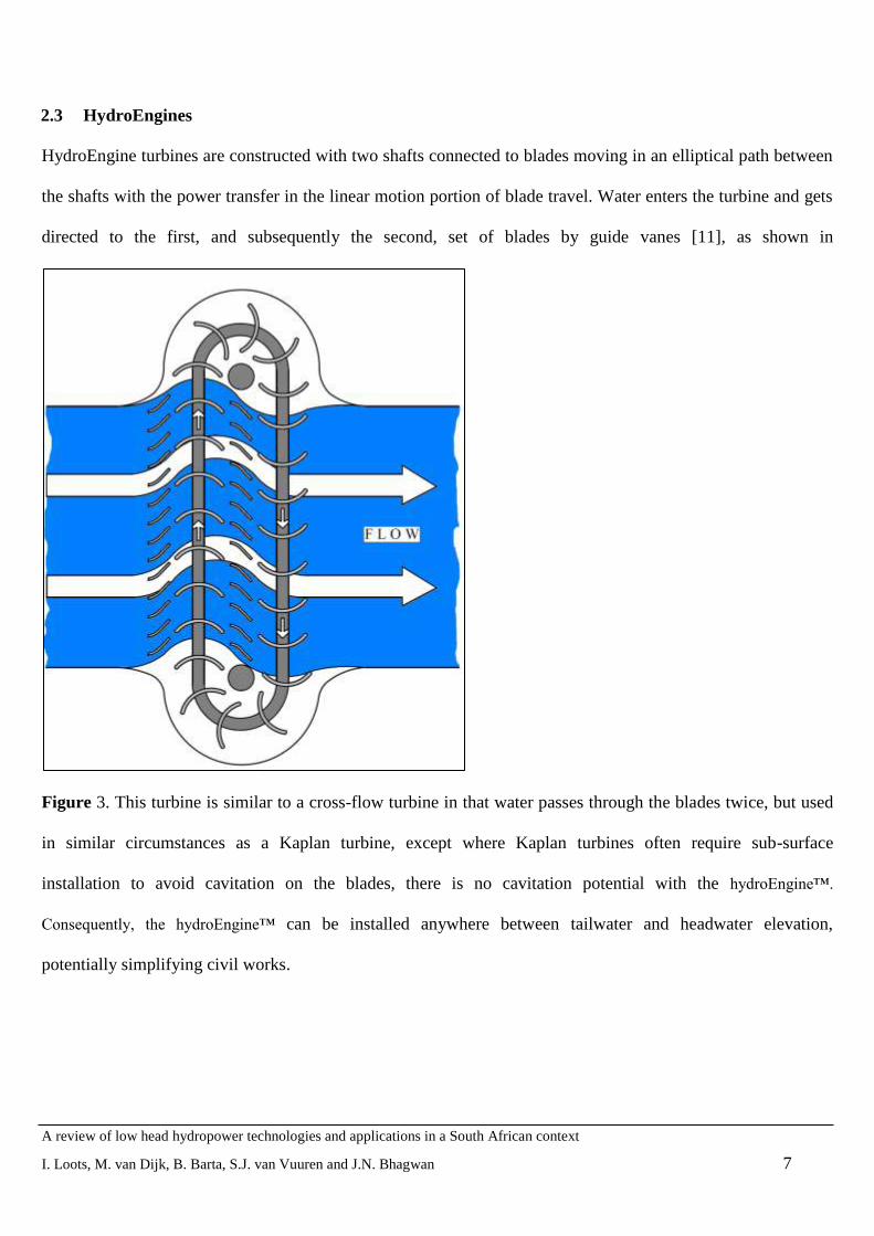
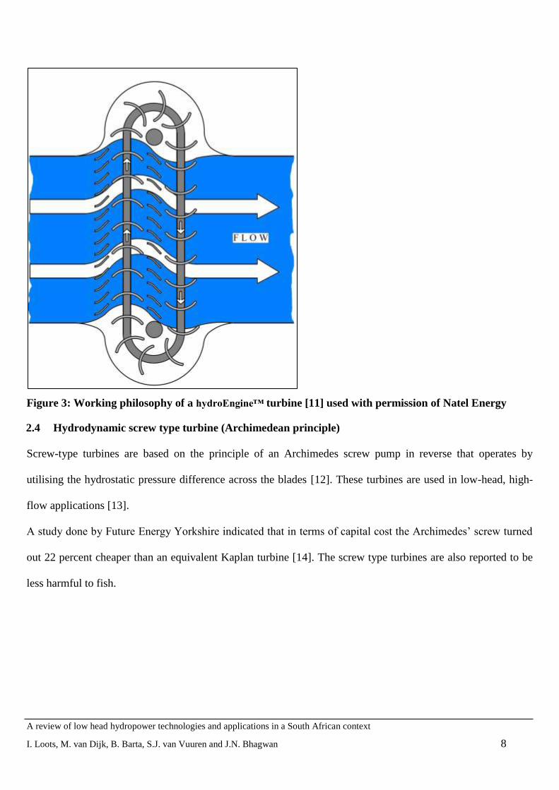
2.3 HydroEngines
HydroEngine turbines are constructed with two shafts connected to blades moving in an elliptical path between
the shafts with the power transfer in the linear motion portion of blade travel. Water enters the turbine and gets
directed to the first, and subsequently the second, set of blades by guide vanes [11], as shown in
Figure 3. This turbine is similar to a cross-flow turbine in that water passes through the blades twice, but used
in similar circumstances as a Kaplan turbine, except where Kaplan turbines often require sub-surface
installation to avoid cavitation on the blades, there is no cavitation potential with the hydroEngine™.
Consequently, the hydroEngine™ can be installed anywhere between tailwater and headwater elevation,
potentially simplifying civil works.
A review of low head hydropower technologies and applications in a South African context
I. Loots, M. van Dijk, B. Barta, S.J. van Vuuren and J.N. Bhagwan 8
Figure 3: Working philosophy of a hydroEngine™ turbine [11] used with permission of Natel Energy
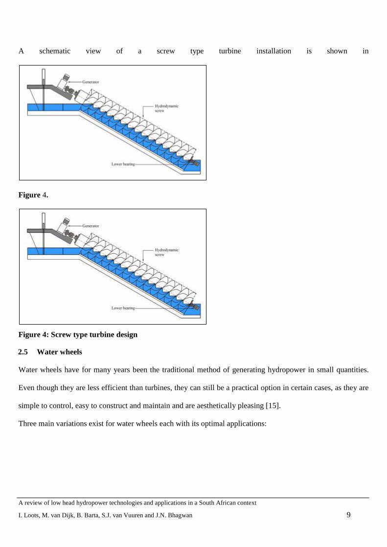
2.4 Hydrodynamic screw type turbine (Archimedean principle)
Screw-type turbines are based on the principle of an Archimedes screw pump in reverse that operates by
utilising the hydrostatic pressure difference across the blades [12]. These turbines are used in low-head, high-
flow applications [13].
A study done by Future Energy Yorkshire indicated that in terms of capital cost the Archimedes‟ screw turned
out 22 percent cheaper than an equivalent Kaplan turbine [14]. The screw type turbines are also reported to be
less harmful to fish.
A review of low head hydropower technologies and applications in a South African context
I. Loots, M. van Dijk, B. Barta, S.J. van Vuuren and J.N. Bhagwan 9
A schematic view of a screw type turbine installation is shown in
Figure 4.
Figure 4: Screw type turbine design
2.5 Water wheels
Water wheels have for many years been the traditional method of generating hydropower in small quantities.
Even though they are less efficient than turbines, they can still be a practical option in certain cases, as they are
simple to control, easy to construct and maintain and are aesthetically pleasing [15].
Three main variations exist for water wheels each with its optimal applications:
A review of low head hydropower technologies and applications in a South African context
I. Loots, M. van Dijk, B. Barta, S.J. van Vuuren and J.N. Bhagwan 10
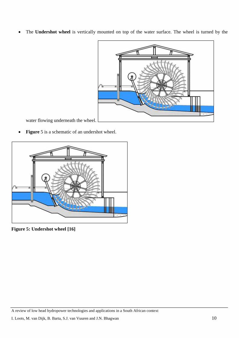
The Undershot wheel is vertically mounted on top of the water surface. The wheel is turned by the
water flowing underneath the wheel.
Figure 5 is a schematic of an undershot wheel.
Figure 5: Undershot wheel [16]

A review of low head hydropower technologies and applications in a South African context
I. Loots, M. van Dijk, B. Barta, S.J. van Vuuren and J.N. Bhagwan 11
The Breastshot wheel receives energy from falling water which hits the blades at the centre height of
the wheel. A breastshot wheel is shown in
Figure 6.
Figure 6: Breastshot wheel [17]
A review of low head hydropower technologies and applications in a South African context
I. Loots, M. van Dijk, B. Barta, S.J. van Vuuren and J.N. Bhagwan 12
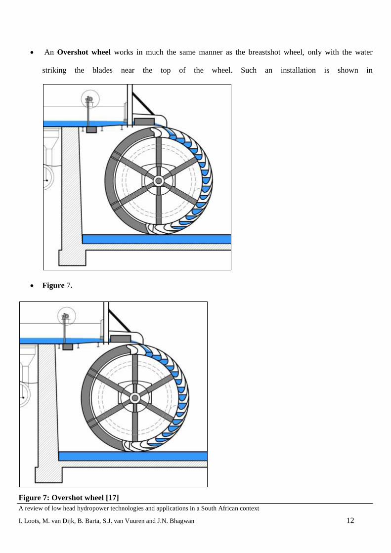
An Overshot wheel works in much the same manner as the breastshot wheel, only with the water
striking the blades near the top of the wheel. Such an installation is shown in
Figure 7.
Figure 7: Overshot wheel [17]

A review of low head hydropower technologies and applications in a South African context
I. Loots, M. van Dijk, B. Barta, S.J. van Vuuren and J.N. Bhagwan 13
2.6 Kaplan, bulb and propeller turbines
Kaplan, bulb and propeller turbines use the axial flow of water to develop hydrodynamic forces that rotate the
runner blades [8]. Unlike with impulse turbines, the Kaplan turbine is completely submerged inside the conduit,
as shown in Figure 8. Guide vanes are installed upstream of the turbine to create inlet swirl, as this ensures
better efficiency.
Figure 8: Typical Kaplan turbine [8] used with permission of IT Power Limited
2.7 Hydrokinetic turbines
Hydrokinetic turbines generate electricity using the kinetic energy of the water in low head applications, instead
of the potential energy due to hydraulic head, as in high pressure applications. These devices therefore capture
energy from moving water, without requiring dams or diversions [18].
Two basic rotors are most commonly used. The Darrieus and Open Savonius rotors are shown in Figure 9.
Most other hydrokinetic rotors work in a similar manner. These rotors can be placed horizontal or vertically.
Figure 9: Darrieus (left) and Open Savonius (right) rotors [19] used with permission of W.B. Hamner

A review of low head hydropower technologies and applications in a South African context
I. Loots, M. van Dijk, B. Barta, S.J. van Vuuren and J.N. Bhagwan 14
2.8 Vortex turbine
The vortex power plant is a type of micro hydro power plant capable of producing energy using a low hydraulic
head. The design is based on a round basin with a central drain. The water passes through a straight inlet and
then passes tangentially into the round basin. A large vortex is formed over the center bottom drain of the basin
and a turbine then withdraws the rotational energy from the vortex, which is converted into electric energy by
means of a generator [20].
Figure 10: Vortex type turbine installation in a river [20]
2.9 Francis turbine
A Francis turbine has radial runners that guide the water to exit at a different radius than the inlet radius.
Francis turbines force the water to flow radially inwards into the runner and turned to emerge axially at the
outlet, as shown in Figure 11 [8].

A review of low head hydropower technologies and applications in a South African context
I. Loots, M. van Dijk, B. Barta, S.J. van Vuuren and J.N. Bhagwan 15
Figure 11: Francis turbine [8] used with permission of IT Power Limited
2.10 Siphon turbines
These turbines have propeller blades, similar to the blades found in Kaplan turbines. The blades are connected
to a turbine shaft that turns a generator. The turbine only starts operating after 30-60 seconds, during which the
generator acts as an electromotor that pumps water into the siphon until it is primed, after which it starts
functioning as a generator (Figure 12) [21].
A review of low head hydropower technologies and applications in a South African context
I. Loots, M. van Dijk, B. Barta, S.J. van Vuuren and J.N. Bhagwan 16
Figure 12: Siphon turbine [21] used with permission of Mavel, a.s.
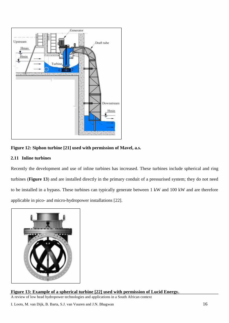
2.11 Inline turbines
Recently the development and use of inline turbines has increased. These turbines include spherical and ring
turbines (Figure 13) and are installed directly in the primary conduit of a pressurised system; they do not need
to be installed in a bypass. These turbines can typically generate between 1 kW and 100 kW and are therefore
applicable in pico- and micro-hydropower installations [22].
Figure 13: Example of a spherical turbine [22] used with permission of Lucid Energy.

A review of low head hydropower technologies and applications in a South African context
I. Loots, M. van Dijk, B. Barta, S.J. van Vuuren and J.N. Bhagwan 17
2.12 Pump as turbine (PAT)
Much research has recently been done on the use of reverse-engineered pumps that can be used as hydraulic
turbines (Figure 14). A standard centrifugal pump is run in reverse to act as a turbine; this is an attractive
option, especially in developing countries, because pumps are mass-produced, and therefore more readily
available and generally cheaper than turbines [23]. However, PATs generally operate at lower efficiencies than
conventional turbines, especially at partial flows.
Williams et al. at the Nottingham Trent University Micro-Hydro Centre [24] have been involved with the
design and installation of various PAT schemes. The university demonstration scheme at a farm in Yorkshire
has been running since 1991. The pumps are now mass-produced and as a result, have the following advantages
for micro-hydro power compared with purpose-made turbines:
Low cost
Available in a number of standard sizes
Short delivery time
Spare parts such as seals and bearings are easily available
Easy installation – uses standard pipe fittings
Standard pump motor can be used as a generator
Figure 14: An example of a pump as turbine [25] used with permission of Andritz, AG, Graz
A review of low head hydropower technologies and applications in a South African context
I. Loots, M. van Dijk, B. Barta, S.J. van Vuuren and J.N. Bhagwan 18
3 TURBINE SELECTION
The key factors to consider in turbine selection and design are the net available head or effective pressure head
across the turbine and the range of flow values or velocities which the turbine must be able to handle. These
values are plotted on operational charts which give envelopes of limiting operational conditions for each type of
turbine. Other factors to consider in turbine selection include specific speed, cavitation and efficiency [7].
Another important factor to consider is flow-rate variation, as turbine efficiency might be severely impacted if
high variation is experienced. For example, Francis and propeller-type turbines have high efficiencies at design
flow, but very low efficiencies for other flow rates. On the other hand cross-flow and pelton turbines can
sustain high efficiencies over a wide range of flow rates.
Both synchronous or induction (asynchronous) generators may be applicable for low-head hydropower
installations; depending on the application. A synchronous generator can be operated in isolation while an
induction generator must be operated in conjunction with other generators. The Applegate Group and Colorado
State University [6] recommend the use of inverter-based low head hydro generation systems, equipped
typically with a solid-state synchronization, that subsequently make them far less prone to “fault” currents.
Van Vuuren, Blersch and Van Dijk [26] developed a Hydropower Retrofitting Model (HRM) which is a
comprehensive, logical and accurate model which can be used in the initial phases of a project to determine the
feasibility of retrofitting hydropower onto an existing dam in SA. The aim of the model is not to generate an
actual design but rather to ascertain financial, environmental and social feasibility at pre-feasibility level and
make a recommendation about whether or not the project is worth further investigation.
A typical hydropower project would require the consideration of technical, legislative, environmental,
socioeconomic and financial aspects. Each of these has a role to play in the determination of feasibility at the
early stages of a project. These aspects are successfully combined into a computer model (HRM) which
requires only a few measurable inputs to produce a recommendation of viability [26]. These include the costs of
electromechanical components and civil works, legislative costs and general costs associated with any civil
engineering project, which are successfully combined into a financial spreadsheet.
A review of low head hydropower technologies and applications in a South African context
I. Loots, M. van Dijk, B. Barta, S.J. van Vuuren and J.N. Bhagwan 19
All potential negative environmental and social impacts are listed for consideration and a method for weighting
their importance and making a recommendation in their regard was developed. The model is comprehensive in
that it includes all necessary costs and factors; and simple in that the inputs required by the user are minimal.
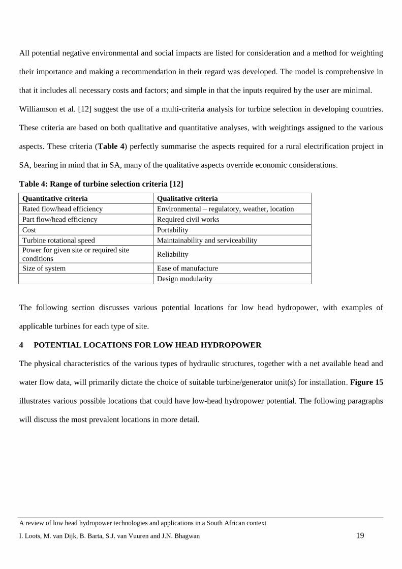
Williamson et al. [12] suggest the use of a multi-criteria analysis for turbine selection in developing countries.
These criteria are based on both qualitative and quantitative analyses, with weightings assigned to the various
aspects. These criteria (Table 4) perfectly summarise the aspects required for a rural electrification project in
SA, bearing in mind that in SA, many of the qualitative aspects override economic considerations.
Table 4: Range of turbine selection criteria [12]
Quantitative criteria Qualitative criteria
Rated flow/head efficiency Environmental – regulatory, weather, location
Part flow/head efficiency Required civil works
Cost Portability
Turbine rotational speed Maintainability and serviceability
Power for given site or required site
conditions Reliability
Size of system Ease of manufacture
Design modularity
The following section discusses various potential locations for low head hydropower, with examples of
applicable turbines for each type of site.
4 POTENTIAL LOCATIONS FOR LOW HEAD HYDROPOWER
The physical characteristics of the various types of hydraulic structures, together with a net available head and
water flow data, will primarily dictate the choice of suitable turbine/generator unit(s) for installation. Figure 15
illustrates various possible locations that could have low-head hydropower potential. The following paragraphs
will discuss the most prevalent locations in more detail.

A review of low head hydropower technologies and applications in a South African context
I. Loots, M. van Dijk, B. Barta, S.J. van Vuuren and J.N. Bhagwan 20
Figure 15: Typical low head hydropower locations
4.1 Dams and barrages
Although large dams are normally associated with significant environmental impacts and only constructed for
large-scale projects, there may exist many opportunities for using small dams and weirs for hydropower
generation [28].
There exists an opportunity to retrofit existing dams and reservoirs (an example of which is shown in Figure
16) with hydropower plants. Instead of dams being constructed for the purpose of hydropower and then having

A review of low head hydropower technologies and applications in a South African context
I. Loots, M. van Dijk, B. Barta, S.J. van Vuuren and J.N. Bhagwan 21
different functions, reservoirs that are already in existence for other purposes can be fitted with hydropower
plants in order to meet base or peak electricity demands. Obviously the application of this form of hydropower
is limited as there are a fixed number of dams in existence (about 3 500 in SA), but the advantages are
numerous, because the energy is there waiting to be harnessed with minimal additional environmental impacts.
Typically, hydropower turbines will be built into new dams or retrofitted to existing infrastructure. Kaplan, bulb
or propeller-type turbines would be most easily installed during dam construction. Siphon-type turbines could
be retrofitted to some low head dams. Smaller dams which only release small volumes for environmental
purposes could consider inline turbines or hydrodynamic screw-type installations.
Figure 16: Clanwilliam Dam, SA [29]
4.2 Irrigation systems
In some irrigation canal systems, turbines can be installed to generate electricity, either through diversion or in
the canal system itself. These systems will normally consist of high-flow, low-head installations [6].
4.2.1 Diversion structures coupled with irrigation systems
Many irrigation systems use diversion systems to canalise water from natural rivers to irrigation canals (Figure
17).
These diversion structures may be ideal sites for the implementation of low head hydropower projects, firstly
because the existing infrastructure can be used to lower construction cost and secondly because many diversion
structures span right across rivers, allowing for the utilisation of all the flow for a hydropower plant [6].
A review of low head hydropower technologies and applications in a South African context
I. Loots, M. van Dijk, B. Barta, S.J. van Vuuren and J.N. Bhagwan 22
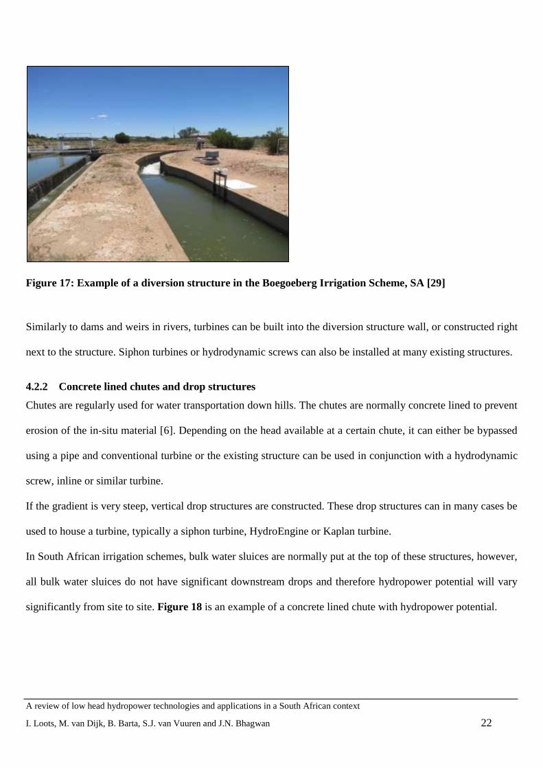
Figure 17: Example of a diversion structure in the Boegoeberg Irrigation Scheme, SA [29]
Similarly to dams and weirs in rivers, turbines can be built into the diversion structure wall, or constructed right
next to the structure. Siphon turbines or hydrodynamic screws can also be installed at many existing structures.
4.2.2 Concrete lined chutes and drop structures
Chutes are regularly used for water transportation down hills. The chutes are normally concrete lined to prevent
erosion of the in-situ material [6]. Depending on the head available at a certain chute, it can either be bypassed
using a pipe and conventional turbine or the existing structure can be used in conjunction with a hydrodynamic
screw, inline or similar turbine.
If the gradient is very steep, vertical drop structures are constructed. These drop structures can in many cases be
used to house a turbine, typically a siphon turbine, HydroEngine or Kaplan turbine.
In South African irrigation schemes, bulk water sluices are normally put at the top of these structures, however,
all bulk water sluices do not have significant downstream drops and therefore hydropower potential will vary
significantly from site to site. Figure 18 is an example of a concrete lined chute with hydropower potential.

A review of low head hydropower technologies and applications in a South African context
I. Loots, M. van Dijk, B. Barta, S.J. van Vuuren and J.N. Bhagwan 23
Figure 18: Example of a concrete lined chute at Schoenmakers in the Orange Fish WTS
4.2.3 Bridges
Vehicle, cattle and pedestrian bridges (Figure 19) may provide many opportunities for easy installation of very
low head turbines in irrigation canals. These structures can provide anchorage for various types of hydrokinetic
turbines. The power produced by these turbines is based on the velocity of the water and area of the turbine,
instead of pressure head and flow.
Figure 19: Pedestrian bridge across the Teebus canal, SA
4.2.4 Flow gauging stations
Most irrigation canals have a flow measuring station (Figure 20), some of which may provide an opportunity
for pico or micro hydropower generation. It is, however, important that flow through the measuring structure is
A review of low head hydropower technologies and applications in a South African context
I. Loots, M. van Dijk, B. Barta, S.J. van Vuuren and J.N. Bhagwan 24
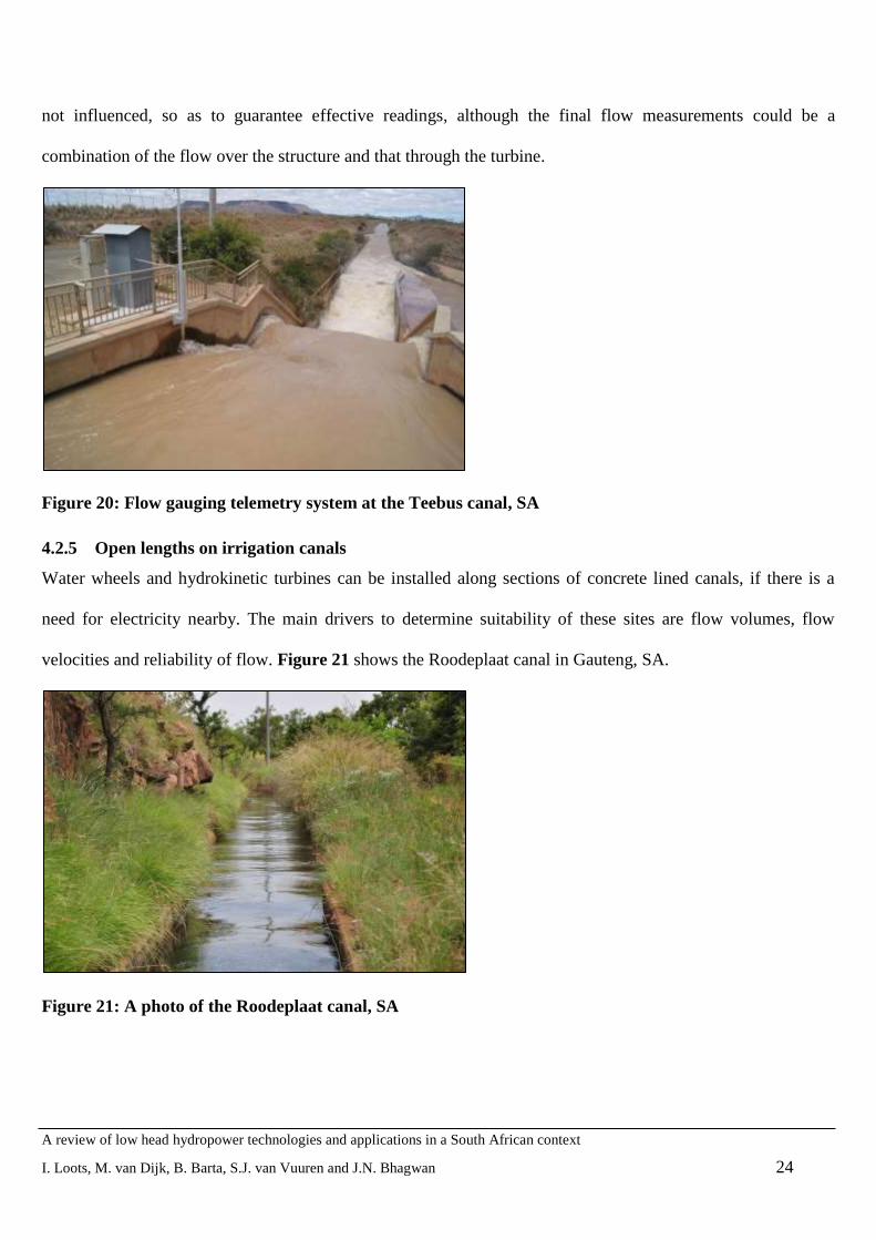
not influenced, so as to guarantee effective readings, although the final flow measurements could be a
combination of the flow over the structure and that through the turbine.
Figure 20: Flow gauging telemetry system at the Teebus canal, SA
4.2.5 Open lengths on irrigation canals
Water wheels and hydrokinetic turbines can be installed along sections of concrete lined canals, if there is a
need for electricity nearby. The main drivers to determine suitability of these sites are flow volumes, flow
velocities and reliability of flow. Figure 21 shows the Roodeplaat canal in Gauteng, SA.
Figure 21: A photo of the Roodeplaat canal, SA

A review of low head hydropower technologies and applications in a South African context
I. Loots, M. van Dijk, B. Barta, S.J. van Vuuren and J.N. Bhagwan 25
4.3 Bulk pipelines and water distribution systems
An often overlooked source of hydropower energy is found in conduits, where pressure-reducing stations
(PRSs) are installed to dissipate excess energy (Figure 22). The energy dissipated by these devices can instead
be captured as hydroelectricity if turbines are installed in the conduits, either by replacing pressure-reducing
valves (PRVs) with a turbine, or by installing the turbine in parallel with the PRV.
Van Vuuren et al. [30] considers in detail the potential and application of hydropower plants in pipelines,
specifically at high pressure points and pressure reducing stations in water distribution systems. Similar
installations may be possible at points with excess pressure, albeit lower pressure than investigated during that
study. Outlets of pipelines into canals or dams could also have potential for low head hydropower applications,
even if pressure reducing measures were not deemed necessary.
The choice of turbine for this type of application would depend on both the available head and the layout of the
tailrace. Pelton or cross-flow turbines could be selected when discharging to atmospheric pressure, i.e. when the
turbine is placed on top of the reservoir. A PAT or Francis turbine could be considered when there will be
backpressure, i.e. when placed at ground level, discharging into an aboveground reservoir.
Figure 22: A photo of a pressure reducing station at the Brandkop Reservoir, SA

A review of low head hydropower technologies and applications in a South African context
I. Loots, M. van Dijk, B. Barta, S.J. van Vuuren and J.N. Bhagwan 26
4.4 Water Transfer Schemes (WTS)
Due to the uneven distribution of rainfall and population in SA, various WTS have been constructed (Figure
23), many of which may provide hydropower opportunities. Infrastructure in these schemes include pipelines,
canals, diversion structures, measuring weirs and other infrastructure also found in irrigation systems. The
turbine types applicable are therefore also similar to those discussed at irrigation systems. Generation potential
of approximately 7 MW exists at the Teebus outlet of the Orange Fish WTS.
Figure 23: A photo of the intake to the Orange-Fish Water Transfer Scheme, SA
4.5 Measuring (flow gauging) weirs
Measuring weirs provide a specific example of structures in many South African rivers where hydropower
installations may be considered. The challenges at these sites are to install a hydropower plant that does not
affect the accuracy of the measuring weir and be safeguarded during peak flood events. An example of a typical
South African gauging weir is shown in Figure 24. There are approximately 3000 flow gauging stations in SA.
Hydropower plants at dams and weirs will normally be built into the dam wall, or constructed right next to the
dam with a short diversion. Kaplan, bulb or propeller-type turbines would be most easily installed during weir
construction. Siphon turbines or hydrodynamic screws can also be installed at many existing weirs.
Hydropower turbines will be built into or retrofitted to weirs. Small schemes may be retrofitted, or planned, at
weirs that are built for other purposes, like flood control, measuring, irrigation, recreation or water abstraction.

A review of low head hydropower technologies and applications in a South African context
I. Loots, M. van Dijk, B. Barta, S.J. van Vuuren and J.N. Bhagwan 27
Figure 24: Typical measuring structure/weir (Neusberg, SA)
4.6 Wastewater treatment works (WWTW) and industrial flows
WWTW are viable sources of hydropower due to the high volume and constant flow of water that generally
flows from such facilities. The flow rates at these treatment works are fairly constant so that no dam or
reservoir is required [31].
According to the European Small Hydropower Association (ESHA) [4], there are two opportunities for
hydropower generation at WWTW: the first is at the inlet to the works and the second is at the outflow.
If a hydropower plant is placed at the inflow of water treatment works, a forebay with trash rack should be
included and the hydro plant should be situated as close as possible to the treatment plant, to maximise the
operational head [4].
The outflow from wastewater treatment works is usually released into natural streams or manmade channels
which transport the water to the river system downstream. These systems convey the water via gravity allowing
all of the additional energy to be extracted.
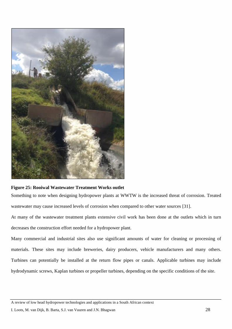
At these outlets the head difference could be between 1 and 10 m which, combined with high flow rates, have
large electricity generation potential (Figure 25 shows the outflow at Rooiwal WWTW, SA).
A review of low head hydropower technologies and applications in a South African context
I. Loots, M. van Dijk, B. Barta, S.J. van Vuuren and J.N. Bhagwan 28
Figure 25: Rooiwal Wastewater Treatment Works outlet
Something to note when designing hydropower plants at WWTW is the increased threat of corrosion. Treated
wastewater may cause increased levels of corrosion when compared to other water sources [31].
At many of the wastewater treatment plants extensive civil work has been done at the outlets which in turn
decreases the construction effort needed for a hydropower plant.
Many commercial and industrial sites also use significant amounts of water for cleaning or processing of
materials. These sites may include breweries, dairy producers, vehicle manufacturers and many others.
Turbines can potentially be installed at the return flow pipes or canals. Applicable turbines may include
hydrodynamic screws, Kaplan turbines or propeller turbines, depending on the specific conditions of the site.
A review of low head hydropower technologies and applications in a South African context
I. Loots, M. van Dijk, B. Barta, S.J. van Vuuren and J.N. Bhagwan 29
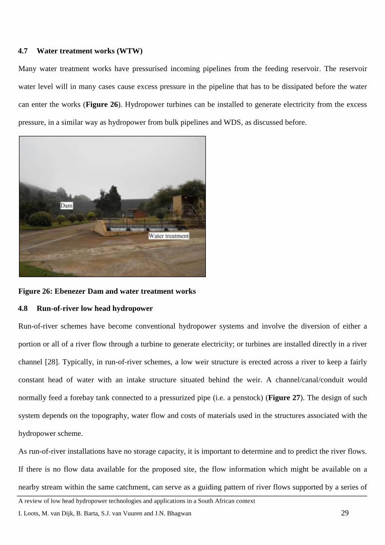
4.7 Water treatment works (WTW)
Many water treatment works have pressurised incoming pipelines from the feeding reservoir. The reservoir
water level will in many cases cause excess pressure in the pipeline that has to be dissipated before the water
can enter the works (Figure 26). Hydropower turbines can be installed to generate electricity from the excess
pressure, in a similar way as hydropower from bulk pipelines and WDS, as discussed before.
Figure 26: Ebenezer Dam and water treatment works
4.8 Run-of-river low head hydropower
Run-of-river schemes have become conventional hydropower systems and involve the diversion of either a
portion or all of a river flow through a turbine to generate electricity; or turbines are installed directly in a river
channel [28]. Typically, in run-of-river schemes, a low weir structure is erected across a river to keep a fairly
constant head of water with an intake structure situated behind the weir. A channel/canal/conduit would
normally feed a forebay tank connected to a pressurized pipe (i.e. a penstock) (Figure 27). The design of such
system depends on the topography, water flow and costs of materials used in the structures associated with the
hydropower scheme.
As run-of-river installations have no storage capacity, it is important to determine and to predict the river flows.
If there is no flow data available for the proposed site, the flow information which might be available on a
nearby stream within the same catchment, can serve as a guiding pattern of river flows supported by a series of

A review of low head hydropower technologies and applications in a South African context
I. Loots, M. van Dijk, B. Barta, S.J. van Vuuren and J.N. Bhagwan 30
short field measurements. The flows are calculated month by month and averaged say over 3 to 5 years. The
flows are then plotted against the percentage of time that the flow is exceeded compiling a flow-duration curve
from which the energy potential at a given site can be determined.
The distribution of seasonal precipitation around SA‟s land-mass is rather diversified making certain areas
suitable and other areas not suitable for the development and operation of run-of-river hydropower.
Turbines used for run-of-river schemes typically include Kaplan, crossflow or propeller-type turbines,
depending on the layout of the system.
Figure 27: Run-of-river opportunity in Orange River, Northern Cape, SA
5 LOW-HEAD HYDROPOWER IN SOUTH AFRICA
ESHA [7] defined low head hydropower as an electricity generation device conveying sustainable volumes of
water at relatively low pressure heads (up to 30 m). Such conditions are typically found in SA at various
hydraulic structures in irrigation canals and rivers, low height dams, gauging weirs, outflow structures of
wastewater plants and some industrial complexes, as described in the previous paragraphs.
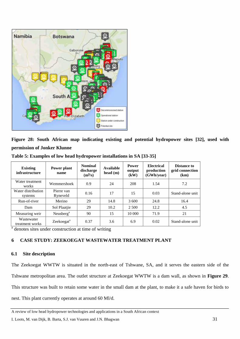
An „African Hydropower Database‟, with a section focusing on South African hydropower installations has
been developed by Jonker Klunne [32]. Figure 28 was retrieved from the database and shows all planned,
existing and decommissioned sites in the country, as well as various potential sites. Most of these sites would
be classified as low head, based on the set classification in Table 1. Table 5provides a summary of some
existing low head hydropower installations in SA.
A review of low head hydropower technologies and applications in a South African context
I. Loots, M. van Dijk, B. Barta, S.J. van Vuuren and J.N. Bhagwan 31
Figure 28: South African map indicating existing and potential hydropower sites [32], used with
permission of Jonker Klunne
Table 5: Examples of low head hydropower installations in SA [33-35]
Existing
infrastructure
Power plant
name
Nominal
discharge
(mᶾ/s)
Available
head (m)
Power
output
(kW)
Electrical
production
(GWh/year)
Distance to
grid connection
(km)
Water treatment
works Wemmershoek 0.9 24 208 1.54 7.2
Water distribution
systems
Pierre van
Ryneveld 0.16 17 15 0.03 Stand-alone unit
Run-of-river Merino 29 14.8 3 600 24.8 16.4
Dam Sol Plaatjie 29 10.2 2 500 12.2 4.5
Measuring weir Neusberga 90 15 10 000 71.9 21
Wastewater
treatment works Zeekoegat
a 0.37 3.6 6.9 0.02 Stand-alone unit
a denotes sites under construction at time of writing
6 CASE STUDY: ZEEKOEGAT WASTEWATER TREATMENT PLANT
6.1 Site description
The Zeekoegat WWTW is situated in the north-east of Tshwane, SA, and it serves the eastern side of the
Tshwane metropolitan area. The outlet structure at Zeekoegat WWTW is a dam wall, as shown in Figure 29.
This structure was built to retain some water in the small dam at the plant, to make it a safe haven for birds to
nest. This plant currently operates at around 60 Ml/d.

A review of low head hydropower technologies and applications in a South African context
I. Loots, M. van Dijk, B. Barta, S.J. van Vuuren and J.N. Bhagwan 32
Figure 29: Zeekoegat WWTW outlet structure
6.2 Flow rates
The average daily flow rate was considered to understand the fluctuation in flow throughout the year. Figure 30
shows the average daily flow rate during the 2013/14 season.
Figure 30: Zeekoegat WWTW flow rate daily average fluctuation
A graph summarising the instantaneous flow for one month in 2014 is shown in Figure 31.
0
20
40
60
80
100
120
140
Flo
w (
Ml/
d)
Date

A review of low head hydropower technologies and applications in a South African context
I. Loots, M. van Dijk, B. Barta, S.J. van Vuuren and J.N. Bhagwan 33
Figure 31: Zeekoegat WWTW instantaneous flow peaks
6.3 Turbine selection
The purpose of this hydropower plant was to demonstrate innovative technologies not yet installed in South
Africa. Two options were therefore considered, namely a propeller-type turbine that could easily be retrofitted
to the dam bottom outlet and a siphon-type turbine. The quotation for a 9.5 kW propeller-type turbine amounted
to approximately R 1.83 million, while the quotation for a 6.7 kW siphon-type turbine amounted to less than
R 0.5 million (with a South African Rand being equal to approximately 0.1USD at the time of writing). Both
these values are for the turbine only, excluding import duties, transport cost or installation, as these rates would
be similar for both options. Although Power et al. [36] indicated that a Kaplan type turbine would be the most
effective solution for such an installation, the purpose of the Zeekoegat plant was demonstrative and thus the
reason for the turbine selection.
Three siphon turbines in parallel were selected for this installation, as they could be easily retrofitted to the
existing structure and provided a more cost-efficient alternative than other options (like a propeller-type
turbine) and can be developed in phases. Figure 12 provides an illustration of a siphon turbine.
The installed capacity per unit would be 6.7 kW, with a net head of 3.6 m and discharge of 0.37 m3/s per unit
(Table 6). The use of parallel units would facilitate operation during low and high flow periods.
0.00
0.50
1.00
1.50
2.00
2.50
3.00
3.50
4.00
Flo
w (
m3
/s)
Date

A review of low head hydropower technologies and applications in a South African context
I. Loots, M. van Dijk, B. Barta, S.J. van Vuuren and J.N. Bhagwan 34
Table 6: Zeekoegat turbine parameters
Turbine type Mavel Siphon TM3
Number of units 3
Net head 3.6 m
Discharge per unit 0.37 m3/s
Power output per unit 6.9 kW
Runner diameter 300 mm
Turbine speed 780 rpm
Type of generator Asynchronous
Generator speed 780 rpm
Generator voltage 3 phase 400 V
Generator frequency 50 Hz
At the time of writing, South African municipalities paid, on average, R 0.73/kWh, which is equivalent to
approximately US$ 0.06 (or € 0.055). Electricity rates in South Africa could therefore be classified as relatively
low, especially in comparison to European electricity tariffs [37]. This factor severely impacts the payback
period of proposed installations and therefore payback periods are generally significantly longer than in many
other countries. Also, as no local turbine manufacturers are currently operational, import duties and
transportation cost also adds a significant percentage to the capital cost, especially on micro and pico scale
installations. Another factor that should be borne in mind when considering the economic feasibility of micro
hydropower projects in South Africa, is the volatility of the South African Rand. It is also a well-known fact
that smaller installations cost more per unit of power delivered, so larger installations tend to have shorter
payback periods (as is the case in [38]).
The investment cost for this system is R1 259 700 (with a South African Rand being equal to approximately
0.1USD at the time of writing). With a conservative estimate of electricity price increases of 10% and discount
rate of 6%, a payback period of about 9 years is projected. However, electricity prices have escalated
significantly in the past six years and indications are that these increases will continue in the foreseeable future.
Therefore, a shorter payback period is likely. Also, government incentives, such as tax rebates, were not
included in this analysis, as the project will be funded by government. According to the Income Tax Act,

A review of low head hydropower technologies and applications in a South African context
I. Loots, M. van Dijk, B. Barta, S.J. van Vuuren and J.N. Bhagwan 35
companies or persons can obtain significant rebates for all verified electricity production during the first year of
operation [39]. The economic analysis is summarised in Table 7.
For many years, the average increase in electricity tariffs in South Africa was below inflation. However, since
April 2008, electricity tariff increases have been significantly above inflation for five years (25.1% average/a).
The main reason for the significant hike in electricity prices is because electricity generation has been
subsidised for many years. It was therefore supplied at below cost to consumers. However, this practice was not
sustainable and electricity prices needed to become cost-reflective to support a sustainable industry in future
[40]. The government‟s electricity providing utility, Eskom, has again requested above-inflation electricity
increases of 23% per annum for the next five years. A sensitivity analysis was executed considering these
electricity price increases and the payback period for this scenario is 5.5 years, which correlates with [36] that
calculated an average payback period of 5.17 years for 27 European countries for a slightly larger installation.
Table 7: Economic analysis for Zeekoegat hydropower plant (South African Rands)
Design life 30 years
Total investment cost 1 259 700
Annual income (present value) 137 100
Annual expenses (present value) 12 600
Net present value 5 769 800
Payback period ± 9 years
Internal rate of return 20%
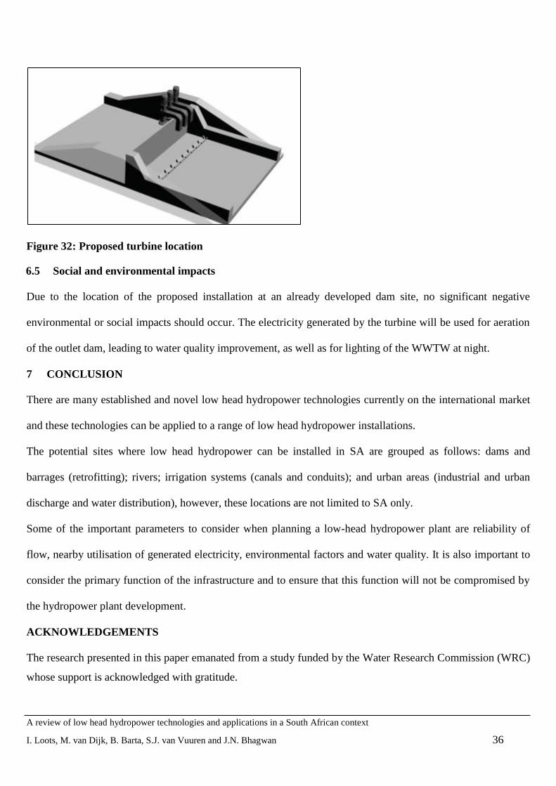
6.4 Turbine retrofit design
The siphon turbines could easily be retrofitted to the outlet spillway of the waste water treatment works. Figure
32 shows the possible location for the turbines.
A review of low head hydropower technologies and applications in a South African context
I. Loots, M. van Dijk, B. Barta, S.J. van Vuuren and J.N. Bhagwan 36
Figure 32: Proposed turbine location
6.5 Social and environmental impacts
Due to the location of the proposed installation at an already developed dam site, no significant negative
environmental or social impacts should occur. The electricity generated by the turbine will be used for aeration
of the outlet dam, leading to water quality improvement, as well as for lighting of the WWTW at night.
7 CONCLUSION
There are many established and novel low head hydropower technologies currently on the international market
and these technologies can be applied to a range of low head hydropower installations.
The potential sites where low head hydropower can be installed in SA are grouped as follows: dams and
barrages (retrofitting); rivers; irrigation systems (canals and conduits); and urban areas (industrial and urban
discharge and water distribution), however, these locations are not limited to SA only.
Some of the important parameters to consider when planning a low-head hydropower plant are reliability of
flow, nearby utilisation of generated electricity, environmental factors and water quality. It is also important to
consider the primary function of the infrastructure and to ensure that this function will not be compromised by
the hydropower plant development.
ACKNOWLEDGEMENTS
The research presented in this paper emanated from a study funded by the Water Research Commission (WRC)
whose support is acknowledged with gratitude.

A review of low head hydropower technologies and applications in a South African context
I. Loots, M. van Dijk, B. Barta, S.J. van Vuuren and J.N. Bhagwan 37
REFERENCES
[1] Price, T. and Probert, D. 1997. Harnessing hydropower: A practical guide. Appl. Energy, 57 (2/3): 175-251.
Elsevier Science Ltd., Great Britain.
[2] European Small Hydropower Association (ESHA). 2006. Small Hydropower for Developing Countries, e-
book. European Small Hydropower Association. Available online:
http://www.esha.be/fileadmin/esha_files/documents/publications/publications/Brochure_SHP_for_Developing_
Countries.pdf. [Accessed 18 February 2013].
[3] Jonker Klunne, W. 2011. Current status of village level hydropower in Eastern and Southern Africa.
Proceedings of the Berlin Micro Energy Conference, 7-8 April 2011, Berlin, Germany.
[4] European Small Hydropower Association (ESHA). 2010. Energy Recovery in Existing Infrastructures with
Small Hydropower Plants: Multipurpose Schemes – Overview and Examples, e-book. European Small
Hydropower Association. Available online: http://www.esha.be/index.php?id=97. [Accessed 26 January 2015].
[5] Barta, B. 2002. Baseline study - hydropower in South Africa. Department of Minerals and Energy. Capacity
Building in Energy Efficiency and Renewable Energy. DME Report No. COWI P54126/EE/RE/70. Department
of Minerals and Energy, Pretoria, South Africa.
[6] Applegate Group and Colorado State University. 2011. Exploring the Viability of Low Head Hydro in
Colorado‟s Existing Irrigation Infrastructure: Final Report. Colorado Department of Agriculture, Colorado,
USA.
[7] European Small Hydropower Association (ESHA). 2004. Guide on How to Develop a Small Hydropower
Plant, e-book. European Small Hydropower Association. Available online:
http://www.ieelibrary.eu/index.php?option=com_jombib&task=showbib&id=624. [Accessed 14 March 2012].
[8] Paish, O. 2002. Small hydro power: technology and current status. Renew. and Sustainable Energy
Reviews, 6 (6): 537–56.
[9] Thornbloom, M. Ngbangadia, D. and Assama, M. 1997. Using micro-hydropower in the Zairian village.
Sol. Energy, 59 (1-3): 75-81.

A review of low head hydropower technologies and applications in a South African context
I. Loots, M. van Dijk, B. Barta, S.J. van Vuuren and J.N. Bhagwan 38
[10] Razak, J.A., Ali, Y. Alghoul, M.A. and Mohammad Said Zainol. 2010. Application of crossflow turbine in
off-grid pico hydro renewable energy system. Proceedings of the American Conference on Applied
Mathematics. January 2010, Harvard University, Cambridge, USA.
[11] Natel Energy. 2013. The HydroEngine: SLH10 and SLH100, Version 4. Natel Energy. Available online:
www.natelenergy.com [Accessed: 17 December 2013].
[12] Williamson, S.J., Stark, B.H. and Booker, J.D. 2014. Low head pico hydro turbine selection using a multi-
criteria analysis. Renew. Energy, 61: 43-50.
[13] International Energy Agency (IEA). 2010. Implementing Agreement for Hydropower Technologies and
Programmes Annex-2: Small Scale Hydropower Sub-Task B2 “Innovative Technologies for Small-Scale
Hydro”: Summary Report. International Energy Agency. Available online:
http://www.smallhydro.com/Programs/innovative-technologies.aspx [Accessed 11 February 2013].
[14] Future Energy Yorkshire (FEY). 2012. Archimedes‟ screw: Copley Hydropower Generator. Yorkshire
Forward. York, United Kingdom.
[15] Natural Resources Canada. 2004. Micro-Hydropower Systems: A Buyer‟s Guide, e-book. Natural
Resources Canada. Available online:
http://www.oregon.gov/energy/RENEW/Hydro/docs/MicroHydroGuide.pdf. [Accessed 3 March 2012].
[16] Fairbarin, W. 1874. Treatise on Mills and Mill-Works, Part 1., 3rd
Edition. Longamns, Green & Co.,
London.
[17] Muller, W. 1899. Die eiseren Wasserrader, Erster Teil: Die Zellenrader & Zweiter Teil: Die Schaufelrader
(The iron water wheels, Part 1: the cell wheels & Part 2: the paddle wheels, in German). Veit & Comp.,
Leipzig.
[18] Kumar, A., T. Schei, A. Ahenkorah, R. Caceres Rodriguez, J.-M.Devernay, M. Freitas, D. Hall, A.
Killingtveit, Z. Liu. 2011. Hydropower. In: IPCC Special Report on Renewable Energy Sources and Climate
Change Mitigation. Cambridge University Press, Cambridge, United Kingdom and New York, NY, USA.

A review of low head hydropower technologies and applications in a South African context
I. Loots, M. van Dijk, B. Barta, S.J. van Vuuren and J.N. Bhagwan 39
[19] Hamner, W.B. 2011. Cross-Axis Hydrokinetic Turbines for Power Generation in Water Currents.
Hydrovolts. Seattle, USA.
[20] Zotlöterer, F. 2013. Zotlöterer Gravitational Vortex Power Plant. Available online:
http://www.zotloeterer.com/ [Accessed 12 Decemebr 2013]
[21] Mavel. 2013. Mavel‟s Micro Turbines. Mavel, a.s. Available online: www.mavel.cz [Accessed: 5
September 2013].
[22] Kanagy, J. 2011. Northwest PowerPipeTM
, an Innovative In-Conduit Power Generating Technology. Lucid
Energy Technologies, LLP. Available online:
http://s36.a2zinc.net/clients/pennwell/hydrovisioninternational2011/Custom/Handout/Speaker9394_Session728
_1.pdf. [Accessed on 28 October 2011].
[23] Williams, A. 2003. Pumps as Turbines: A User‟s Guide (2nd
edition). Practical Action Publishing Ltd,
Warwickshire, UK.
[24] Williams, A.A., Smith, N.P.A., Bird, C., and Howard, M. 1998. Pumps as Turbines and Induction Motors
as Generators for Energy Recovery in Water Supply Systems. Journal CIWEM. UK. June. 175 - 8.
[25] Mellacher, B. and Fiedler, T. 2013. ANDRITZ micro hydropower. Proceeding of the Clean Power Africa
Conference, 14-15 May 2013, Cape Town, South Africa.
[26] Van Vuuren, S.J., Blersch, C.L. and Van Dijk, M. 2011. Modelling the feasibility of retrofitting
hydropower to existing South African dams. Proceedings of the Water Research Commission 40-Year
Celebration Conference, 31 August – 1 September 2011, Kempton Park, South Africa. Available online:
http://www.wrc.org.za. [Accessed 5 September 2012].
[28] Harvey, A., Brown, A., Hettiarachi, P. and Inversin, A. 1993. Micro-Hydro Design Manual: A Guide to
Small-scale Hydropower Schemes. Practical Action Publishing Ltd, United Kingdom.
[29] Department of Water Affairs (DWA). 2013. Development and Implimentation of Irrigation Water
Management Plans to Improve Water Use Efficiency in the Agricultural Sector. Department of Water Affairs,
Pretoria, South Africa.

A review of low head hydropower technologies and applications in a South African context
I. Loots, M. van Dijk, B. Barta, S.J. van Vuuren and J.N. Bhagwan 40
[30] Van Vuuren, S.J. 2010. A High Level Scoping Investigation into the Potential of Energy Saving and
Production/Generation in the Supply of Water through Pressurized Conduits. WRC Project No. K8/839/3.
WRC Report No. KV 238/10. Water Research Commission, Pretoria, South Africa.
[31] Lam, P.W. 2008. Application of Hydroelectric Technology in Stonecutters Island Sewage Treatment
Works. Research and Development Report no. RD 2047. Drainage Services Department. Hong Kong, China.
[32] Jonker Klunne, W. E. 2015. African Hydropower Database. Available online: www.hydro4africa.net.
[Accessed on 28 January 2015].
[33] Culwick, L. and Bode, C. 2011. City of Cape Town Mini Hydro Prefeasibility Study. Sidala Energy
Solutions. Available online: www.carbonn.org. [Accessed on 16 February 2015].
[34] De Koker, V. 2010. Bethlehem Hydro. Civil Engineering December 2010, Vol. 18, No. 11, 74 –8.
[35] West, N. 2013. Innovative design of the Neusberg Hydro Electric Power Plant – South Africa‟s first run-
of-river mini-hydro under the REIPP program. Proceedings of the Clean Power Africa Conference, 14-15 May
2013, Cape Town, South Africa.
[36] Power, C., Coughlan, P., McNabola, A. 2014. Development of an evaluation method for hydropower
energy recovery in wastewater treatment plants: Case studies in Ireland and the UK, Sustainable Energy
Technologies & Assessments, 7: 166 – 177.
[37] Eurostat. 2014. Electricity and natural gas price statistics. Available online: ec.europa.eu/eurostat/statistics-
explained. [Accessed on 1 May 2015].
[38] Kucukali, S. 2010. Hydropower potential of municipal water supply dams in Turkey: A case study in
Ulutan Dam. Energy Policy, 38(11): 6534-6539.
[39] South Africa. 1962. The Income Tax Act, Act 58 of 1962 as amended, Pretoria, South Africa.
[40] Eskom. 2012. Revenue Application: Multi-Year Price Determination 2013/14 to 2017/18 (MYPD 3).
Available online: www.eskom.co.za . [Accessed 10 December 2012].


