
A Review of Flexible and Weaveable Fiber-Like ... · PDF fileA Review of Flexible and...
15
PostDoc Journal Vol. 1, No. 12, December 2013 Journal of Postdoctoral Research www.postdocjournal.com A Review of Flexible and Weaveable Fiber-Like Supercapacitors Chuizhou Meng Weldon School of Biomedical Engineering, Purdue University, West Lafayette, IN 47907, USA E-mail: [email protected] Abstract The rapid development of small, thin, lightweight, and even flexible wearable electronic devices has led to a growing need for matchable textile energy storage devices with high performance. Among different sources, supercapacitors are capable of providing higher power density than their counterparts and are drawing tremendous interest from both research and engineering communities. Just in the past two years, flexible and weaveable fiber-like supercapacitors have emerged and attracted increasing research attention. In this up-to-date review, after a brief introduction of supercapacitor principle, performance, and electrode/electrolyte materials, we summarize the current development of two types of fiber-like supercapacitors, as well as various advanced fiber electrode materials that have been utilized. Finally, we discuss integrated fiber-like power systems incorporated with fiber-like supercapacitors and fiber- like energy harvesting and conversion devices, and identify new research trends in materials, fabrication, and future applications. 1 Introduction of Supercapacitors The need to utilize energy on a broad scale in a modern society necessitates the development of large and small energy harvesting, conversion and storage systems. Among them, electric energy storage systems have attracted great attention in the past several decades because of their important role in directly providing power to run various equipment and devices. As a type of robustly developing energy storage devices, electrochemical capacitors, mostly known as supercapacitors, bridge the gap between conventional capacitors and batteries, by providing high power density, fast charge/ discharge rate, extremely long cycling life time, and broad working temperature range (Simon, 2008). Since the first patent on supercapacitors based on highly porous carbon electrodes was granted to Becker at General Electric Corp. in 1957 (Becker, 1957), supercapacitors have been becoming more and more important in complementing or even completely replacing batteries in many applications from electric grids, hybrid vehicles to a variety of electronic devices (Kotz, 2000). These promising applications prompted the U.S. Department of Energy to initiate supercapacitor short- and long-term development programs. 1.1 Principle and Performance In general, a supercapacitor consists of two porous supercapacitive electrodes and a separator sandwiched between them. The sandwich-like electrode/separator/electrode device structure is immersed in an aqueous or organic electrolyte. The separator prevents the contact of the two electrodes (hence preventing the short circuit of the whole device) while allowing electrolyte ions freely passing through. To maintain sufficient functional liquid electrolyte in the device from leakage that is also harmful to our living environment, the whole system needs to be encapsulated in packaging such as box-like and button-like containers (Simon, 2008; Burke, 2000). Supercapacitors store energy mainly based on two types of mechanisms: electric double-layer capacitors and pseudo-capacitors (Kotz, 2000). a) Electric double-layer capacitors (EDLCs) store energy through a physical process of ion adsorption, i.e., the charge accumulation of electrostatically positive and negative charges
Transcript of A Review of Flexible and Weaveable Fiber-Like ... · PDF fileA Review of Flexible and...
PostDoc Journal Vol. 1, No. 12, December 2013
Journal of Postdoctoral Research www.postdocjournal.com
A Review of Flexible and Weaveable Fiber-Like Supercapacitors Chuizhou Meng Weldon School of Biomedical Engineering, Purdue University, West Lafayette, IN 47907, USA E-mail: [email protected]
Abstract The rapid development of small, thin, lightweight, and even flexible wearable electronic devices has led to a growing need for matchable textile energy storage devices with high performance. Among different sources, supercapacitors are capable of providing higher power density than their counterparts and are drawing tremendous interest from both research and engineering communities. Just in the past two years, flexible and weaveable fiber-like supercapacitors have emerged and attracted increasing research attention. In this up-to-date review, after a brief introduction of supercapacitor principle, performance, and electrode/electrolyte materials, we summarize the current development of two types of fiber-like supercapacitors, as well as various advanced fiber electrode materials that have been utilized. Finally, we discuss integrated fiber-like power systems incorporated with fiber-like supercapacitors and fiber-like energy harvesting and conversion devices, and identify new research trends in materials, fabrication, and future applications.
1 Introduction of Supercapacitors The need to utilize energy on a broad scale in a modern society necessitates the development of large and small energy harvesting, conversion and storage systems. Among them, electric energy storage systems have attracted great attention in the past several decades because of their important role in directly providing power to run various equipment and devices. As a type of robustly developing energy storage devices, electrochemical capacitors, mostly known as supercapacitors, bridge the gap between conventional capacitors and batteries, by providing high power density, fast charge/ discharge rate, extremely long cycling life time, and broad working temperature range (Simon, 2008). Since the first patent on supercapacitors based on highly porous carbon electrodes was granted to Becker at General Electric Corp. in 1957 (Becker, 1957), supercapacitors have been becoming more and more important in complementing or even completely replacing batteries in many applications from electric grids, hybrid vehicles to a variety of electronic devices (Kotz, 2000). These promising applications prompted the U.S. Department of Energy to
initiate supercapacitor short- and long-term development programs.
1.1 Principle and Performance In general, a supercapacitor consists of two porous supercapacitive electrodes and a separator sandwiched between them. The sandwich-like electrode/separator/electrode device structure is immersed in an aqueous or organic electrolyte. The separator prevents the contact of the two electrodes (hence preventing the short circuit of the whole device) while allowing electrolyte ions freely passing through. To maintain sufficient functional liquid electrolyte in the device from leakage that is also harmful to our living environment, the whole system needs to be encapsulated in packaging such as box-like and button-like containers (Simon, 2008; Burke, 2000).
Supercapacitors store energy mainly based on two types of mechanisms: electric double-layer capacitors and pseudo-capacitors (Kotz, 2000). a) Electric double-layer capacitors (EDLCs) store energy through a physical process of ion adsorption, i.e., the charge accumulation of electrostatically positive and negative charges

17 Journal of Postdoctoral Research 2013: 16-30
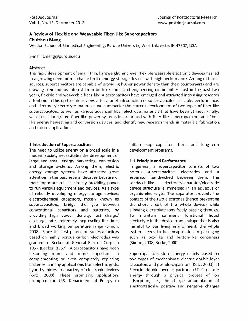
separately residing on the interface between electrode and electrolyte (Figure 1a). The energy storage process in EDLCs is non-faradic, i.e., ideally there is no charge transfer occurring through the electrode active material to the electrolyte ions. b) Pseudo-capacitors store energy through fast and reversible redox reactions on the surface of electrode active material. The energy storage process in pseudo-capacitors is faradic, i.e., capacitance is associated with a charge-transfer process that takes place to an extent limited by a finite amount (nanometer-thick) of electrode active material with available surface (somewhat battery-like in its behavior), so pseudo-capacitors can provide typically 10-100 times higher specific capacitance than EDLCs (Pandolfo, 2006).
Supercapacitors efficiently bridge the gap between conventional capacitors (e.g., dielectric capacitors or electrolytic capacitors) and batteries (e.g., lead-acid batteries, nickel-metal hydride batteries or lithium ion batteries) (Figure 1b) (Kotz, 2000). Compared with conventional capacitors, supercapacitors use highly porous electrode active materials (e.g., activated carbon with an extremely high specific surface area of
up to > 2000 m2/g) and thus can accumulate huge charges, leading to a much higher energy density. Compared with batteries that store energy based on slow thermodynamic chemical reactions, supercapacitors utilize the mechanisms of fast physical charge absorption and reversible redox actions and thus can provide faster charge/discharge rate at a high current load, leading to a much higher power density with much longer cycling life time.
A variety of key performance parameters such as capacitance, energy and power have been used to characterize supercapacitors. The specific capacitance (Cs in F/g) of an invested single active electrode can be calculated upon the following equation:
(1)
where Ccell is the overall capacitance of the device obtained from electrochemical measurements, and m is the total mass of the two electrodes. Herein the factor of “2” is associated with the fact that the device consists of two in-series EDLCs (Figure 1a, C1 = C2 for symmetric electrodes). The energy density (Es in
Figure 1. (a) Schematic illustrations of an electric double-layer capacitor (EDLC) in its charged state and the simplified equivalent circuit; (b) Ragone plots showing energy and power densities of conventional capacitors, supercapacitors, batteries and fuel cells. Reprinted with permission from (Pandolfo, 2006), Copyright © 2006 Elsevier Ltd.

Chuizhou Meng 18 Wh/kg) and power density (Ps in W/kg) of a supercapacitor are calculated based on the following two equations, respectively:
(2)
(3)
where V is the maximum working voltage, R is the internal resistance obtained from electrochemical measurements. Here the power is the maximum value that can be obtained when the internal resistance of the device equals the external load resistance. The measured capacitance, energy and power can also be normalized by the volume of the electrode active material, and the specific volumetric values are believed to be more practically useful as compared to gravimetric ones (Gogotsi, 2011). In case of fiber-like supercapacitors, length-normalized capacitances are more important for accurately characterizing device performance for practical textile applications. The overall performance of supercapacitors should be optimized in order to meet the goal of increasing the power density as much as possible while maintaining an acceptable energy density with stable electrochemical cyclic ability.
1.2 Electrode and Electrolyte There are three main types of electrode supercapacitive materials that are frequently used for supercapacitors: a) highly porous carbon materials (Frackowiak, 2001; Frackowiak, 2007), e.g., activated carbon, carbon fibers, carbon aerogel and carbon nanotubes (CNTs), and newly discovered graphene (Wang, 2009), carbide-derived carbon (Heon, 2011), and carbon onions (Pech, 2010); b) transition metal oxides (Deng, 2011), e.g., RuO2, MnO2, NiO, Co3O4, etc.; c) electrically conducting polymers (Snook, 2011), e.g., polyaniline (PANI), polypyrrole (PPy), and polythiophene (PTh) and its derivatives. In general, carbon materials mainly store energy based on EDLCs that exhibit true capacitance behavior and excellent electrochemical stability upon repeated cycling but the overall specific
capacitance is relatively low; while metal oxides and conducting polymers have large pseudo-capacitance but low electrical conductivity and poor cycling life time. Thus, people dedicate much effort in compositing carbon materials with metal oxides or/and conducting polymers to obtain synthetic-enhanced overall performance (Meng, 2009; Zhou, 2010). For instance, nanosized NiO, Co3O4 or Mn2O3 nanoparticles were directly synthesized on the cross-stacking super-aligned CNT films by in-situ thermo-decompositing corresponding salts (Zhou, 2010). The CNT/metal oxide composite films without using traditional heavy metallic current collectors nevertheless showed excellent performance, including high specific capacitance (500 F/g), reliable electrochemical stability (4.5% degradation in 2500 cycles) and high rate capability (245 F/g at 155 A/g). In another work, compared with conventional brittle PANI pellet electrodes, interesting paper-like CNT/PANI composite films were obtained by directly chemically polymerizing aniline monomers to form nanometer-thick PANI coating layer on the CNT network template (Meng, 2009). Enhanced electrochemical performance including higher specific capacitance (424 F/g), lower internal resistivity, and more electrochemical stability (10% degradation in 1000 cycles) were also found.
The electrolyte is another critical component that plays an important role in supercapacitor performance. The requirements for a good electrolyte include a wide working voltage window, high electrochemical stability, high ionic concentration and conductivity, low viscosity, low toxicity, etc. (Xiong, 2013) Typical electrolytes can be classified into three main types: aqueous electrolytes, organic liquid electrolytes and room-temperature ionic liquid electrolytes. Aqueous electrolytes, such as acids (e.g., H2SO4) or alkalis (e.g., KOH) dissolved in water, tend to have higher ionic conductivity (up to 1 S/cm), leading to a low internal resistance (Kotz, 2000). However, the maximum working voltage of aqueous electrolyte is restricted to 1.23 V (decomposition voltage of water). On the
19 Journal of Postdoctoral Research 2013: 16-30
other hand, organic electrolyte and ionic electrolyte can provide a broad working voltage window typically higher than 2 V but with a higher internal resistance (ionic conductivity of 10-2 S/cm) (Kotz, 2000). According equation (2) and (3), the energy and power of a supercapacitor have a quadratic dependence upon maximum working voltage, so most of the presently available supercapacitor products use an organic electrolyte to obtain higher energy storage performance (Kotz, 2000).
The aforementioned three kinds of electrolyte are all in the form of liquid. The drawback is that packaging is needed to encapsulate the environmental harmful liquid chemicals. Additional bulky packaging in practical application severely limits the whole energy storage device being developed to be smaller, thinner, more lightweight and even flexible. Recently, a new family of solid-state polymer electrolytes have attracted much attention because they offer many advantages over their liquid counterparts (Xiong, 2013; Meng, 2010): a) Solid-state polymer electrolytes are made by binding electrolyte ions into a polymer matrix. Therefore there is no leakage issue and bulky packaging can be eliminated. b) Solid-state electrolytes offer bi-functionality of providing electrolyte ions and serving as a separator between two electrodes. c) Solid-state polymer electrolyte binds the two electrodes together into an integrated unit, which is beneficial in developing flexible energy storage devices. Because of the foregoing advantages, solid-state electrolytes open a promising way of designing energy storage devices in unconventional ways, e.g., flexible paper-like supercapacitors (Meng, 2010; Xiong, 2013; Meng, 2013), ultrasmall sub-millimeter-sized supercapacitors (Meng, 2013), and fiber-like supercapacitors (Meng, 2013; Fu, 2012), in order to meet the versatile requirements of rapidly growing modern markets. In practice, solid-state polymer electrolyte is fabricated by mixing electrolyte solution (e.g., acid or alkalis in water, Li salt in organic solution, and ionic liquid) within specific
polymer matrix (e.g., polyvinyl alcohol PVA, polyethylene oxide PEO, polyvinylidene difluoride PVDF). The maximum working voltage of solid-state polymer electrolyte is determined by the electrolyte solution part: < 1.23 V for aqueous solution-based electrolyte and > 2 V for organic solution- or ionic liquid-based electrolyte. Due to the existence of polymer component, the ionic conductivity of solid-state polymer electrolyte is lower (10-3-10-2 S/cm) compared with liquid electrolyte (Choudhury, 2006).
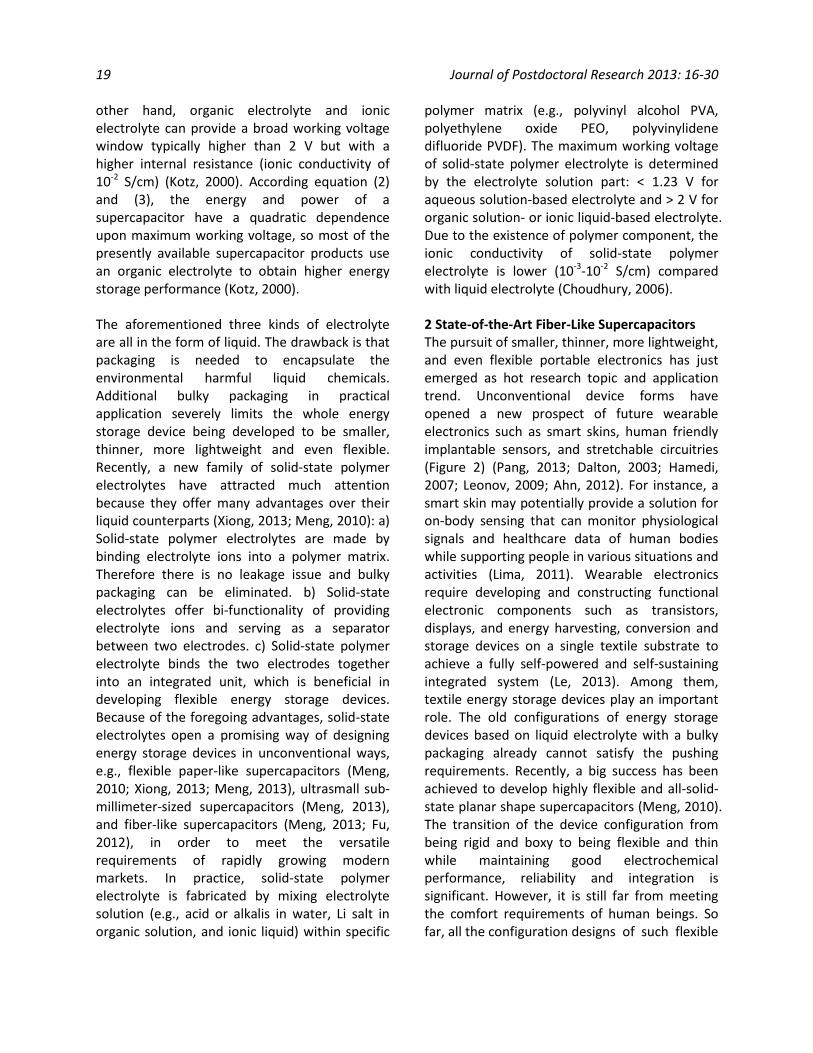
2 State-of-the-Art Fiber-Like Supercapacitors The pursuit of smaller, thinner, more lightweight, and even flexible portable electronics has just emerged as hot research topic and application trend. Unconventional device forms have opened a new prospect of future wearable electronics such as smart skins, human friendly implantable sensors, and stretchable circuitries (Figure 2) (Pang, 2013; Dalton, 2003; Hamedi, 2007; Leonov, 2009; Ahn, 2012). For instance, a smart skin may potentially provide a solution for on-body sensing that can monitor physiological signals and healthcare data of human bodies while supporting people in various situations and activities (Lima, 2011). Wearable electronics require developing and constructing functional electronic components such as transistors, displays, and energy harvesting, conversion and storage devices on a single textile substrate to achieve a fully self-powered and self-sustaining integrated system (Le, 2013). Among them, textile energy storage devices play an important role. The old configurations of energy storage devices based on liquid electrolyte with a bulky packaging already cannot satisfy the pushing requirements. Recently, a big success has been achieved to develop highly flexible and all-solid-state planar shape supercapacitors (Meng, 2010). The transition of the device configuration from being rigid and boxy to being flexible and thin while maintaining good electrochemical performance, reliability and integration is significant. However, it is still far from meeting the comfort requirements of human beings. So far, all the configuration designs of such flexible

Chuizhou Meng 20
energy storage devices are based on a solid planar structure and therefore they are not breathable, i.e., they do not allow body’s sweat and environmental air pass through them freely (Wang, 2013). It is promising to develop next-generation of energy storage devices in the form of fibers, yarns or wires, which are feasible to be woven into textiles or other similar structures in our daily life to exhibit unique new applications for developing true wearable electronic devices.
The goal of developing fiber-like supercapacitors is to fabricate a novel kind of energy storage device that is in the form of ultrathin and flexible fiber while maintaining excellent electrochemical performance. The key lies in fabricating fiber-like electrode active materials and designing novel device structure/configuration. Considerable efforts towards these two directions have occurred in the very recent years.
There are mainly two types of fiber-like supercapacitive electrode: a) Carbon-based fiber electrodes such as CNT fibers and graphene fibers (Meng, 2013; Le, 2013; Xu, 2013; Chen, 2013; Ren, 2013; Lee, 2013; Wang, 2013; Cai, 2013). They are highly porous and provide considerable amount of EDLC. They also have strong mechanical properties and can be directly used as fiber electrodes or as fiber template for pseudo-capacitive electrode materials coating on. b) Metal wire- or metal-coated plastic wire-based electrodes (Harrison, 2013; Li, 2013; Fu, 2012). The metal wire or plastic wire only serves as the mechanical and electrical template for supercapacitive electrode materials coating on. This kind of fiber template does not play a role in storing energy but accounts for a considerable weight and volume portion of the whole device.
With regard to the device configuration of fiber-like supercapacitors, there are mainly two types,
Figure 2. Schematic illustrations of flexible mechanical and electrical sensors: (a) E-skins; (b) Wearable and skin-attachable sensors; (c) Implantable devices for in vivo diagnostics; (d) Advanced sensors with additional functionalities. Reprinted with permission from (Pang, 2013), Copyright © 2013 Wiley Periodicals, Inc.
21 Journal of Postdoctoral Research 2013: 16-30
i.e., two-ply fiber-like supercapacitors and coaxial fiber-like supercapacitors. They are both variations of the conventional device configuration of electrode/separator/electrode sandwich type. The former is fabricated by twining two fiber electrodes together with a separator or gel polymer electrolyte between them (Figure 3a) (Meng, 2013; Xu, 2013; Ren, 2013; Li, 2013; Fu, 2012; Lee, 2013; Wang, 2013; Cai, 2013; Ren, 2013). The latter is fabricated by assembling a core fiber electrode, a separator or gel polymer electrolyte, and an outer coating electrode layer by layer (Figure 4i) (Le, 2013; Chen, 2013; Harrison, 2013). Even though fiber-like supercapacitors based on liquid electrolyte with well-designed packaging plastic tube have been rarely achieved (Fu, 2012), it appears that the packaging technique of assembling fiber electrodes, separator and liquid electrolyte within such thin and long dimension still remains very challenging. In contrast, the aforementioned advantages offered by solid-state electrolytes are particularly beneficial in fabricating fiber-like supercapacitors with more ease and developing the devices to be more multi-functional, i.e., ultrathin, flexible and even stretchable.
2.1 Two-Ply Fiber-Like Supercapacitors CNTs have becoming a promising candidate electrode active material for developing fiber-like supercapacitors. Compared with traditional activated carbon powders, CNTs have attracted interest for supercapacitors because of their unique advantages: a) the electrical conductivity of CNT is greater than 100 S/cm, much higher than activated carbon (2.5 S/cm) (Meng, 2009; Meng, 2010); b) most of the open space in CNTs is in the form of mesopores (2 to 50 nm) that contribute to EDLCs and fast ion transport rates, whereas the pore distribution of activated carbons contains a large portion of micropores (< 2nm) and macropores (> 50nm) that cannot be utilized for EDLCs (Zhang, 2007). What is more, CNT fibers can be easily spun from arrays of CNT forests, and they can be directly used as fiber electrodes. For instance, Xu et al. reported a
wire-like stretchable supercapacitor using two CNT fibers as fiber electrodes with gel H2SO4/PVA polymer electrolyte (Xu, 2013). Firstly the CNT fibers with a diameter of 15 µm were spun from a vertically aligned CNT array, and then two CNT fibers were coated with gel polymer electrolyte by means of dip-coating and twined together to form a wire-like supercapacitor. To make a stretchable supercapacitor, the prepared straight wire-like supercapacitor was glued on the surface of a 100% prestrained spandex fiber with additional gel polymer electrolyte as an adhesive. Herein, the spandex fiber was used as the stretchable template because the synthetic fiber had exceptional elasticity (usually 500%-800% elongation). After the prestrain on the spandex fiber was released, a sinusoidal buckling wire-like supercapacitor with stretchability attaching on the spandex fiber was obtained. The wire-like stretchable supercapacitor had a specific area capacitance of up to 4.99 mF/cm2 and was able to undergo a large cyclic tensile strain of 100%.
In order to further improve the porous structure and hence increase the specific surface area, additional mesopore-based carbon materials can be directly deposited on CNT fibers. For instance, Prof. Peng’s group reported a series of wire-like supercapacitors using a series of MWNT/ordered mesoporous carbon (OMC) nanocomposite fibers with different compositions as fiber electrodes (Ren, 2013; Ren, 2013). Firstly different amount of OMC was synthesized on the stack of three-layer MWNT sheets through a solution process, and then the resulting nanocomposite sheets were scrolled to form a nanocomposite fiber. After coated with gel polymer electrolyte, two MWNT/OMC nanocomposite fibers were twined together to produce a wire-like supercapacitor. As the OMC content increased from 46% to 90%, the diameter of the nanocomposite fiber increased from 30 to 140 µm. The highest specific length capacitance was found to be 1.907 mF/cm (corresponding to a specific area capacitance of 39.67 mF/cm2) with 87 wt% OMC, a number that is 20 times that of pure MWNT fiber electrodes (0.0017 mF/cm and 1.97
Chuizhou Meng 22
mF/cm2). No obvious performance decrease was observed when the wire-like supercapacitor was woven into textile structures.
Apart from CNTs, graphene fibers also attracted attention in fabricating fiber-like supercapacitors. Since the mechanically exfoliated graphene monolayer was first observed and characterized in 2004 (Novoselov, 2004), a great deal of research attention worldwide has been drawn in applications of supercapacitors. Among various graphene materials fabricated through different methods, reduced graphene oxide (rGO) is most frequently used due to its low-cost, scalability, wet-chemical properties and the high density of chemically active defect sites. Recently, Meng et
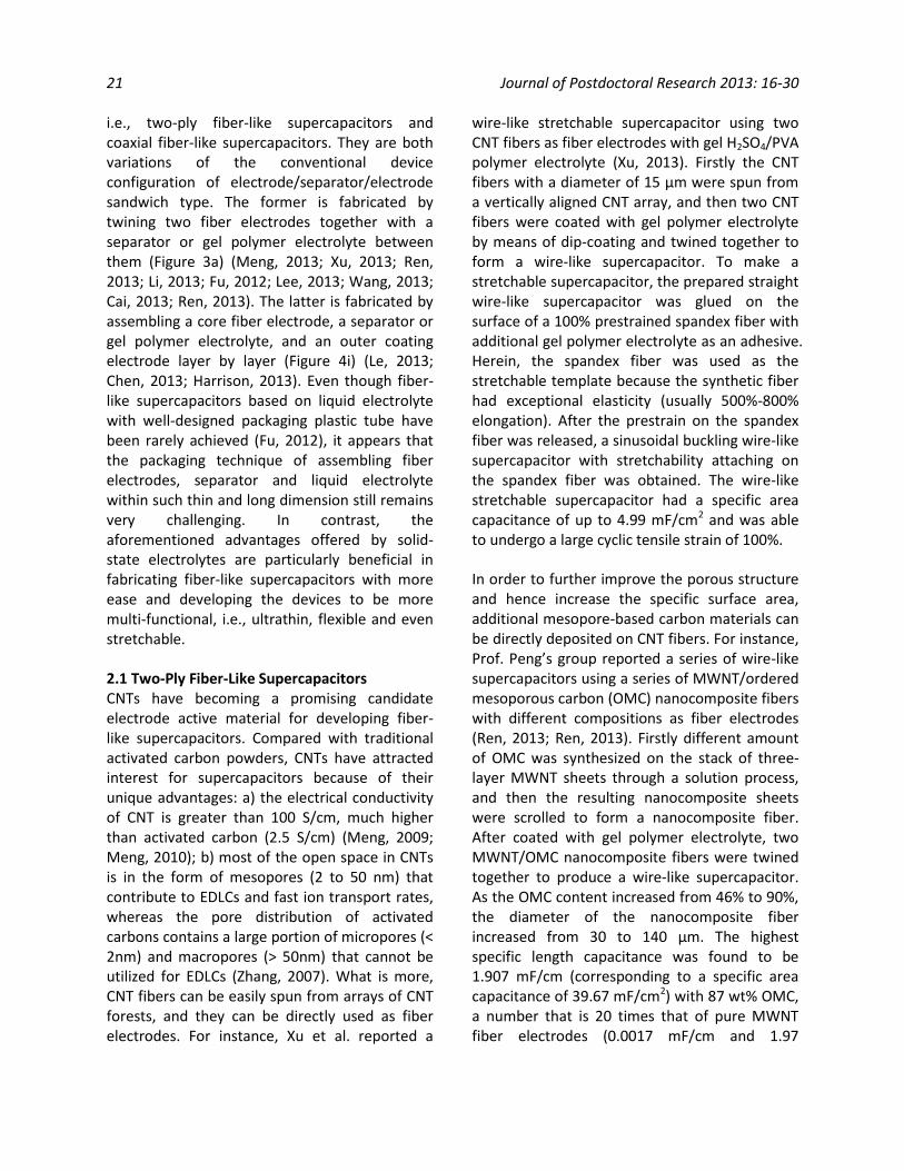
al. reported a fiber-like supercapacitor using graphene fiber coated with porous 3D-graphene networks as fiber electrodes with gel H2SO4/PVA polymer electrolyte (Figure 3) (Meng, 2013). Firstly graphene fiber with a diameter of 30-35 µm was fabricated through a one-step dimensionally-confined hydrothermal strategy from aqueous suspensions, and then porous 3D-graphene network was deposited on the graphene fiber by directly electrochemically electrolyzing graphene oxide aqueous suspension (3 mg/mL GO in 0.1 M LiClO4) at a potential of -1.2 V vs. Ag/AgCl (3 M KCl). The obtained graphene fiber/3D-graphene showed an electrical conductivity of 10-20 S/cm, slightly higher than that of pure graphene fiber. The
Figure 3. (a) Schematic illustration of a two-ply fiber-like supercapacitor fabricated from two twined graphene fiber/3D-graphene composite fibers with polyelectrolyte; (b, c) SEM images of the side view and cross-section view of a graphene fiber/3D-graphene composite fiber showing the core graphene fiber surrounding with standing graphene sheets; (d) Photo of the two-ply fiber-like supercapacitor in its bending state; (e) Photo of the textile embedded with two two-ply fiber-like supercapacitors. Reprinted with permission from (Meng, 2013), Copyright © 2013 Wiley Periodicals, Inc.
23 Journal of Postdoctoral Research 2013: 16-30
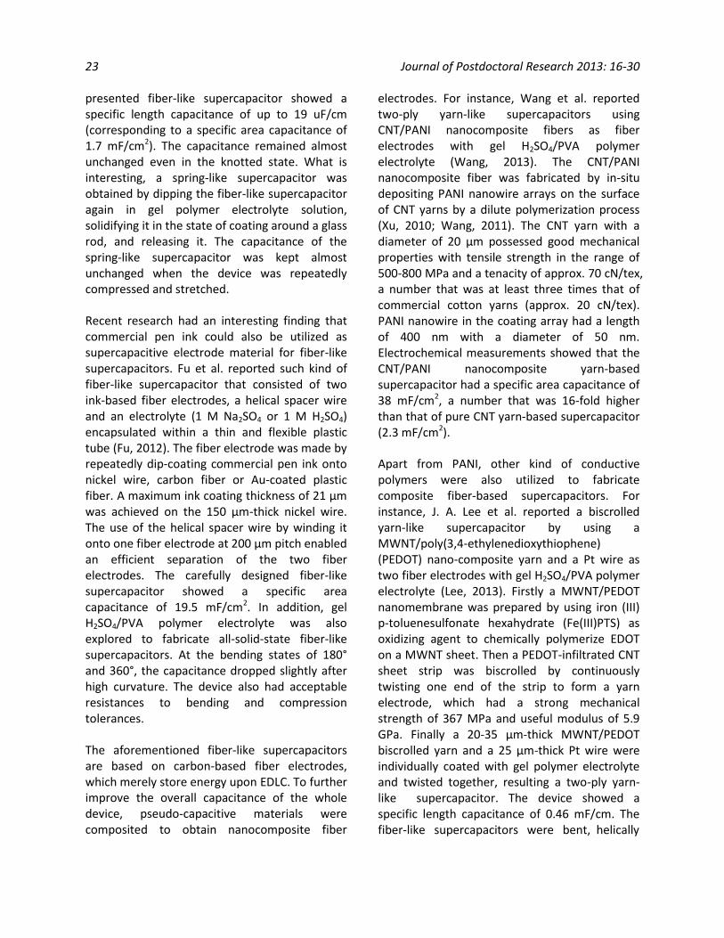
presented fiber-like supercapacitor showed a specific length capacitance of up to 19 uF/cm (corresponding to a specific area capacitance of 1.7 mF/cm2). The capacitance remained almost unchanged even in the knotted state. What is interesting, a spring-like supercapacitor was obtained by dipping the fiber-like supercapacitor again in gel polymer electrolyte solution, solidifying it in the state of coating around a glass rod, and releasing it. The capacitance of the spring-like supercapacitor was kept almost unchanged when the device was repeatedly compressed and stretched.
Recent research had an interesting finding that commercial pen ink could also be utilized as supercapacitive electrode material for fiber-like supercapacitors. Fu et al. reported such kind of fiber-like supercapacitor that consisted of two ink-based fiber electrodes, a helical spacer wire and an electrolyte (1 M Na2SO4 or 1 M H2SO4) encapsulated within a thin and flexible plastic tube (Fu, 2012). The fiber electrode was made by repeatedly dip-coating commercial pen ink onto nickel wire, carbon fiber or Au-coated plastic fiber. A maximum ink coating thickness of 21 µm was achieved on the 150 µm-thick nickel wire. The use of the helical spacer wire by winding it onto one fiber electrode at 200 µm pitch enabled an efficient separation of the two fiber electrodes. The carefully designed fiber-like supercapacitor showed a specific area capacitance of 19.5 mF/cm2. In addition, gel H2SO4/PVA polymer electrolyte was also explored to fabricate all-solid-state fiber-like supercapacitors. At the bending states of 180° and 360°, the capacitance dropped slightly after high curvature. The device also had acceptable resistances to bending and compression tolerances.
The aforementioned fiber-like supercapacitors are based on carbon-based fiber electrodes, which merely store energy upon EDLC. To further improve the overall capacitance of the whole device, pseudo-capacitive materials were composited to obtain nanocomposite fiber
electrodes. For instance, Wang et al. reported two-ply yarn-like supercapacitors using CNT/PANI nanocomposite fibers as fiber electrodes with gel H2SO4/PVA polymer electrolyte (Wang, 2013). The CNT/PANI nanocomposite fiber was fabricated by in-situ depositing PANI nanowire arrays on the surface of CNT yarns by a dilute polymerization process (Xu, 2010; Wang, 2011). The CNT yarn with a diameter of 20 µm possessed good mechanical properties with tensile strength in the range of 500-800 MPa and a tenacity of approx. 70 cN/tex, a number that was at least three times that of commercial cotton yarns (approx. 20 cN/tex). PANI nanowire in the coating array had a length of 400 nm with a diameter of 50 nm. Electrochemical measurements showed that the CNT/PANI nanocomposite yarn-based supercapacitor had a specific area capacitance of 38 mF/cm2, a number that was 16-fold higher than that of pure CNT yarn-based supercapacitor (2.3 mF/cm2).
Apart from PANI, other kind of conductive polymers were also utilized to fabricate composite fiber-based supercapacitors. For instance, J. A. Lee et al. reported a biscrolled yarn-like supercapacitor by using a MWNT/poly(3,4-ethylenedioxythiophene) (PEDOT) nano-composite yarn and a Pt wire as two fiber electrodes with gel H2SO4/PVA polymer electrolyte (Lee, 2013). Firstly a MWNT/PEDOT nanomembrane was prepared by using iron (III) p-toluenesulfonate hexahydrate (Fe(III)PTS) as oxidizing agent to chemically polymerize EDOT on a MWNT sheet. Then a PEDOT-infiltrated CNT sheet strip was biscrolled by continuously twisting one end of the strip to form a yarn electrode, which had a strong mechanical strength of 367 MPa and useful modulus of 5.9 GPa. Finally a 20-35 µm-thick MWNT/PEDOT biscrolled yarn and a 25 µm-thick Pt wire were individually coated with gel polymer electrolyte and twisted together, resulting a two-ply yarn-like supercapacitor. The device showed a specific length capacitance of 0.46 mF/cm. The fiber-like supercapacitors were bent, helically
Chuizhou Meng 24
wound or woven into a textile glove, and capacitance decays of 2% after 2000 cycles, 8% after 10000 cycles and 1% after 10000 cycles were observed, respectively, indicating the excellent cycling performance under different flexible states.
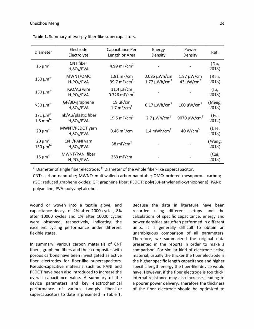
In summary, various carbon materials of CNT fibers, graphene fibers and their composites with porous carbons have been investigated as active fiber electrodes for fiber-like supercapacitors. Pseudo-capacitive materials such as PANI and PEDOT have been also introduced to increase the overall capacitance value. A summary of the device parameters and key electrochemical performance of various two-ply fiber-like supercapacitors to date is presented in Table 1.
Because the data in literature have been recorded using different setups and the calculations of specific capacitance, energy and power densities are often performed in different units, it is generally difficult to obtain an unambiguous comparison of all parameters. Therefore, we summarized the original data presented in the reports in order to make a comparison. For similar kind of electrode active material, usually the thicker the fiber electrode is, the higher specific length capacitance and higher specific length energy the fiber-like device would have. However, if the fiber electrode is too thick, internal resistance may also increase, leading to a poorer power delivery. Therefore the thickness of the fiber electrode should be optimized to
Table 1. Summary of two-ply fiber-like supercapacitors.
Diameter Electrode
Electrolyte Capacitance Per Length or Area
Energy Density
Power Density
Ref.
15 µma) CNT fiber
H2SO4/PVA 4.99 mF/cm2 - -
(Xu,
2013)
150 µma) MWNT/OMC H3PO4/PVA
1.91 mF/cm 39.7 mF/cm2
0.085 µWh/cm 1.77 µWh/cm2
1.87 µW/cm 43 µW/cm2
(Ren,
2013)
130 µma) rGO/Au wire H3PO4/PVA
11.4 µF/cm 0.726 mF/cm2
- - (Li,
2013)
>30 µma) GF/3D-graphene
H2SO4/PVA 19 µF/cm
1.7 mF/cm2 0.17 µWh/cm2 100 µW/cm2
(Meng,
2013)
171 µma) 1.8 mmb)
Ink/Au/plastic fiber H2SO4/PVA
19.5 mF/cm2 2.7 µWh/cm2 9070 µW/cm2 (Fu,
2012)
20 µma) MWNT/PEDOT yarn
H2SO4/PVA 0.46 mF/cm 1.4 mWh/cm3 40 W/cm3
(Lee,
2013)
20 µma) 150 µmb)
CNT/PANI yarn H2SO4/PVA
38 mF/cm2 - - (Wang,
2013)
15 µma) MWNT/PANI fiber
H3PO4/PVA 263 mF/cm - -
(Cai,
2013)
a) Diameter of single fiber electrode; b) Diameter of the whole fiber-like supercapacitor;
CNT: carbon nanotube; MWNT: multiwalled carbon nanotube; OMC: ordered mesoporous carbon;
rGO: reduced graphene oxides; GF: graphene fiber; PEDOT: poly(3,4-ethylenedioxythiophene); PANI:
polyaniline; PVA: polyvinyl alcohol.
25 Journal of Postdoctoral Research 2013: 16-30
make a well trade-off between energy and power towards practical applications.
2.2 Coaxial Fiber-Like Supercapacitors Apart from fiber-like supercapacitors based on two fiber electrodes twisted together, there have been a few attempts of developing coaxial fiber-like supercapacitors. Compared with two-ply fiber-like supercapacitors, the fabrication process of coaxial fiber-like supercapacitors is more complicated and special care should be taken to make sure the micrometer-thick middle gel polymer electrolyte layer indeed prevents the short between the core electrode and the outer electrode throughout the whole device length. However, a coaxial fiber-like supercapacitor is a novel energy storage device built on a single fiber structure, and it may not have the potential issue of delamination of two fiber electrodes during practical application as it is for two-ply fiber-like supercapacitors. Research towards this direction is just on an initial stage.
Prof. Peng’s group reported a fiber-like supercapacitor with a coaxial fiber structure (Chen, 2013). The device had been designed and produced from the aligned CNT fiber and CNT sheet as the core and outer electrodes, respectively, with a gel H3PO4/PVA polymer electrolyte sandwiched between them. Both the CNT fibers and CNT sheets were dry-spun from CNT arrays. The CNT fiber was controlled from 6-40 μ m in diameter and the CNT sheet was controlled from 0.1-4 cm in width. They showed an electrical conductivity of 102-103 S/cm and a tensile strength of 102-103 MPa. To fabricate a coaxial fiber-like supercapacitor, a CNT fiber was firstly dipped into gel polymer electrolyte, which could be infiltrated into the porous structure of the CNT fiber and coated on the surface of the CNT fiber to form a separator layer. A CNT sheet was then scrolled on the prepared fiber to produce the desired coaxial device structure. To improve electrochemical performance, the whole device was finally dipped in gel polymer electrolyte again to make sure that all the CNTs
in the outer sheet had been embedded in the electrolyte. The optimal mass ratio between the CNT fiber and CNT sheet was found to be appropriately 1:1 to obtain the highest electrochemical performance. The thickness of the whole coaxial fiber-like supercapacitor was 43 µm, which consisted of 11.5 µm-thick core CNT fiber, 5.5 µm-thick gel polymer electrolyte, and 26 µm-thick CNT sheet layers. The coaxial fiber-like supercapacitor showed a specific length capacitance of 29 µF/cm. In addition, the capacitance retained 97.2% after bending at 180° for over 100 cycles and 81.6% after being stretched by 10% for 75 cycles. What is more, the capacitance of the device remained almost unchanged after being knotted or woven into textiles.
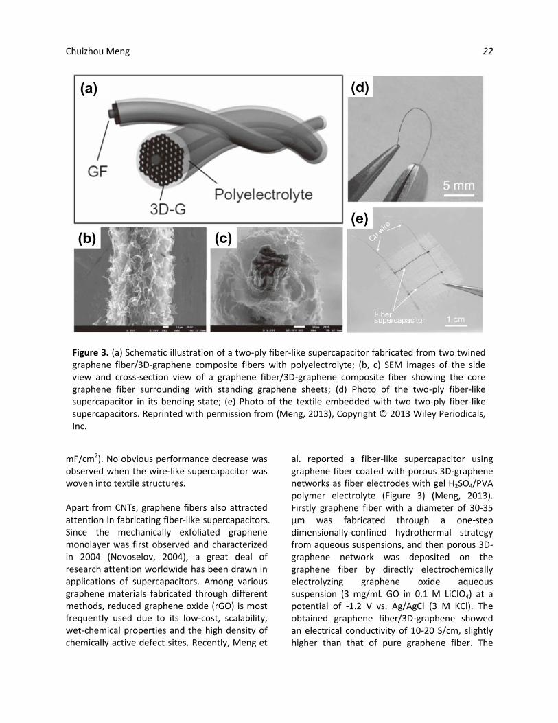
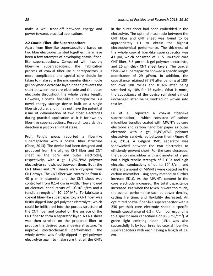
Le et al. reported a coaxial fiber-like supercapacitor, which consisted of carbon microfiber bundles coated with MWNTs as core electrode and carbon nanofiber paper as outer electrode with a gel H3PO4/PVA polymer electrolyte sandwiched between them (Figure 4) (Le, 2013). A Celgard 3501 separator was sandwiched between the two electrodes to efficiently prevent short. For the core electrode, the carbon microfiber with a diameter of 7 µm had a high tensile strength of 2 GPa and high electrical conductivity of up to 103 S/cm, and different amount of MWNTs were coated on the carbon microfiber using spray method to further increase EDLC. As the MWNTs content in the core electrode increased, the total capacitance increased. But when the MWNTs were too much, the overall performance such as power density, cycling life time, and flexibility decreased. An optimized coaxial fiber-like supercapacitor with a 230 µm-thick core electrode shoed a specific length capacitance of 6.3 mF/cm (corresponding to a specific area capacitance of 86.8 mF/cm2). A green light emitting diode (LED) was also successfully lit by four in-series coaxial fiber-like supercapacitors with each having a length of 3.6 cm.
Chuizhou Meng 26
Harrison et al. reported a coaxial fiber-like supercapacitor by using Chinese ink on stainless steel and activated carbon as the core and outer electrodes, respectively, with a gel H3PO4/PVA polymer electrolyte sandwiched between them (Harrison, 2013). The stainless steel was used as the mechanical template of the whole device, and a simple dip-coating method was used to prepare the multiple functional coated layers of Chinese ink/gel polymer electrolyte/activated carbon/silver paint one after another. The thickness of the whole coaxial fiber-like supercapacitor was 410 µm, which consisted of 25 µm-thick ink, 75 µm-thick gel polymer electrolyte and 85 µm-thick activated carbon layer. The specific length capacitance was measured to be 0.1 mF/cm (corresponding to a
specific area capacitance of 3.18 mF/cm2). When woven into a piece of fabric, the 70 cm-long coaxial fiber-like supercapacitor showed unchanged electrochemical performance as its original value before its integration with the fabric.
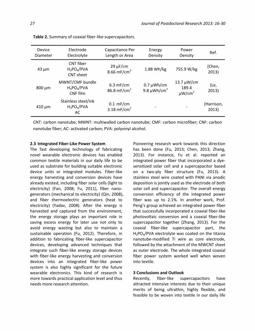
Table 2 provides a summary of device structure parameters and electrochemical performance of coaxial fiber-like supercapacitors reported in literature to date. Similar to the practice followed in Table 1, we chose to summarize the original data rather than translate the results into a common set of units.
Figure 4. Schematic illustration of the fabrication process of coaxial fiber-like supercapacitors: (a) preparing MWCNT suspension; (b) spray-coating MWNTs onto planar CMFs; (c) assembling MWCNT/CMF bundles after removing surfactant; (h) Soaking MWCNT/CMF bundles with gel polymer electrolyte, and wrapping it with separator and CNF film; (i) Schematic illustration and photo of a coaxial fiber-like supercapacitor. (d, f) SEM images of single uncoated CMF and single CMF coated with MWCNTs; (e) SEM image of a MWCNTs/CMF bundle; (g) SEM image of a CNF film and its enlargement on upper right (the inset is a digital photo of the bendable CNF film). Reprinted with permission from (Le, 2013), Copyright © 2013 American Chemical Society.
27 Journal of Postdoctoral Research 2013: 16-30
2.3 Integrated Fiber-Like Power System The fast developing technology of fabricating novel wearable electronic devices has enabled common textile materials in our daily life to be used as substrate for building suitable electronic device units or integrated modules. Fiber-like energy harvesting and conversion devices have already existed, including fiber solar cells (light to electricity) (Fan, 2008; Fu, 2011), fiber nano-generators (mechanical to electricity) (Qin, 2008), and fiber thermoelectric generators (heat to electricity) (Yadav, 2008). After the energy is harvested and captured from the environment, the energy storage plays an important role in saving excess energy for later use not only to avoid energy wasting but also to maintain a sustainable operation (Fu, 2012). Therefore, in addition to fabricating fiber-like supercapacitor devices, developing advanced techniques that integrate such fiber-like energy storage devices with fiber-like energy harvesting and conversion devices into an integrated fiber-like power system is also highly significant for the future wearable electronics. This kind of research is more towards practical application level and thus needs more research attention.
Pioneering research work towards this direction has been done (Fu, 2013; Chen, 2013; Zhang, 2013). For instance, Fu et al. reported an integrated power fiber that incorporated a dye-sensitized solar cell and a supercapacitor based on a two-ply fiber structure (Fu, 2013). A stainless steel wire coated with PANI via anodic deposition is jointly used as the electrode of both solar cell and supercapacitor. The overall energy conversion efficiency of the integrated power fiber was up to 2.1%. In another work, Prof. Peng’s group achieved an integrated power fiber that successfully incorporated a coaxial fiber-like photovoltaic conversion and a coaxial fiber-like supercapacitor together (Zhang, 2013). For the coaxial fiber-like supercapacitor part, the H3PO4/PVA electrolyte was coated on the titania nanotube-modified Ti wire as core electrode, followed by the attachment of the MWCNT sheet as outer electrode. The whole integrated coaxial fiber power system worked well when woven into textile.
3 Conclusions and Outlook Recently, fiber-like supercapacitors have attracted intensive interests due to their unique merits of being ultrathin, highly flexible, and feasible to be woven into textile in our daily life
Table 2. Summary of coaxial fiber-like supercapacitors.
Device Diameter
Electrode Electrolyte
Capacitance Per Length or Area
Energy Density
Power Density
Ref.
43 µm CNT fiber
H3PO4/PVA CNT sheet
29 µF/cm 8.66 mF/cm2
1.88 Wh/kg 755.9 W/kg (Chen, 2013)
800 µm MWNT/CMF bundle
H3PO4/PVA CNF film
6.3 mF/cm 86.8 mF/cm2
0.7 µWh/cm 9.8 µWh/cm2
13.7 µW/cm 189.4
µW/cm2
(Le, 2013)
410 µm Stainless steel/ink
H3PO4/PVA AC
0.1 mF/cm 3.18 mF/cm2
- - (Harrison,
2013)
CNT: carbon nanotube; MWNT: multiwalled carbon nanotube; CMF: carbon microfiber; CNF: carbon
nanotube fiber; AC: activated carbon; PVA: polyvinyl alcohol.

Chuizhou Meng 28 for developing future wearable electronic devices, especially when they are integrated with fiber-like energy harvesting and conversion devices to achieve fiber-like power systems. Compared to conventional supercapacitors, fabrication of fiber-like supercapacitors is relatively new. For this reason, it is worthwhile to review the primary scientific literature to learn trends and identify existing benchmarks. To date, considerable attempts have been made to fabricate fiber electrodes using various advanced supercapacitive electrode materials such as CNT fibers, graphene fibers, and their composites with pseudo-capacitive materials. Currently two types of device configurations, i.e., two-ply fiber-like supercapacitors and coaxial fiber-like supercapacitors, have been commonly used for research and development.
There are many challenges of developing high-performance fiber-like supercapacitors on the way towards practical applications in wearable electronics, including: a) For future structure design of fiber electrodes, a major challenge still remains to increase the overall specific capacitance and energy density by either increasing the thickness of the fiber electrode or introducing more pseudo-capacitance materials without sacrificing the mechanical properties, cycling life time and power density in a given length. b) Apart from mechanical performance characterization on fiber electrodes such as CNT fibers and graphene fibers, thorough mechanical measurements are still needed for the whole fiber-like supercapacitor devices. c) More choices for solid-state electrolytes that are based on organic electrolyte or ionic liquid are required so that the working voltage of a fiber-like supercapacitor can be obtained higher than 2.5 V to further increase energy and power densities. d) The long-term goal should be focused on developing techniques of producing fiber-like supercapacitors in large scale and waving them into a truly textile energy storage device that is ready to be used for powering wearable electronic devices.
References
1. C. Pang, C. Lee and K. Y. Suh, J. Appl. Polym. Sci., 2013, 130, 1429-1441.
2. A. G. Pandolfo and A. F. Hollenkamp, J. Power Sources, 2006, 157, 11-27.
3. Y. N. Meng, Y. Zhao, C. G. Hu, H. H. Cheng, Y. Hu, Z. P. Zhang, G. Q. Shi and L. T. Qu, Adv. Mater., 2013, 25, 2326-2331.
4. V. T. Le, H. Kim, A. Ghosh, J. Kim, J. Chang, Q. A. Vu, D. T. Pham, J. H. Lee, S. W. Kim and Y. H. Lee, ACS Nano, 2013, 7, 5940-5947.
5. P. Xu, T. Gu, Z. Cao, B. Wei, J. Yu, F. Li, J.-H. Byun, W. Lu, Q. Li and T.-W. Chou, Advanced Energy Materials, 2013, published online, DOI: 10.1002/aenm.201300759.
6. X. Chen, L. Qiu, J. Ren, G. Guan, H. Lin, Z. Zhang, P. Chen, Y. Wang and H. Peng, Adv. Mater., 2013, published online, DOI: 10.1002/adma.201301519.
7. D. Harrison, F. L. Qiu, J. Fyson, Y. M. Xu, P. Evans and D. Southee, Phys. Chem. Chem. Phys., 2013, 15, 12215-12219.
8. J. Ren, W. Bai, G. Guan, Y. Zhang and H. Peng, Adv. Mater., 2013, published online, DOI: 10.1002/adma.201302498.
9. P. Simon and Y. Gogotsi, Nat. Mater., 2008, 7, 845-854.
10. Y. R. Li, K. X. Sheng, W. J. Yuan and G. Q. Shi, Chem. Commun., 2013, 49, 291-293.
11. Y. P. Fu, X. Cai, H. W. Wu, Z. B. Lv, S. C. Hou, M. Peng, X. Yu and D. C. Zou, Adv. Mater., 2012, 24, 5713-5718.
12. J. A. Lee, M. K. Shin, S. H. Kim, H. U. Cho, G. M. Spinks, G. G. Wallace, M. D. Lima, X. Lepro, M. E. Kozlov, R. H. Baughman and S. J. Kim, Nat. Commun., 2013, 4.
13. K. Wang, Q. H. Meng, Y. J. Zhang, Z. X. Wei and M. H. Miao, Adv. Mater., 2013, 25, 1494-1498.
14. H. E. Becker, US Patent, 1957, No. 2 800 616.

29 Journal of Postdoctoral Research 2013: 16-30
15. Z. B. Cai, L. Li, J. Ren, L. B. Qiu, H. J. Lin and H. S. Peng, J. Mater. Chem. A, 2013, 1, 258-261.
16. R. Kotz and M. Carlen, Electrochim. Acta, 2000, 45, 2483-2498.
17. A. Burke, J. Power Sources, 2000, 91, 37-50.
18. Y. Gogotsi and P. Simon, Science, 2011, 334, 917-918.
19. E. Frackowiak and F. Beguin, Carbon, 2001, 39, 937-950.
20. E. Frackowiak, Phys. Chem. Chem. Phys., 2007, 9, 1774-1785.
21. Y. Wang, Z. Q. Shi, Y. Huang, Y. F. Ma, C. Y. Wang, M. M. Chen and Y. S. Chen, J. Phys. Chem. C, 2009, 113, 13103-13107.
22. M. Heon, S. Lofland, J. Applegate, R. Nolte, E. Cortes, J. D. Hettinger, P. L. Taberna, P. Simon, P. H. Huang, M. Brunet and Y. Gogotsi, Energy & Environmental Science, 2011, 4, 135-138.
23. D. Pech, M. Brunet, H. Durou, P. H. Huang, V. Mochalin, Y. Gogotsi, P. L. Taberna and P. Simon, Nat. Nanotech., 2010, 5, 651-654.
24. W. T. Deng, X. B. Ji, Q. Y. Chen and C. E. Banks, RSC Adv., 2011, 1, 1171-1178.
25. G. A. Snook, P. Kao and A. S. Best, J. Power Sources, 2011, 196, 1-12.
26. C. Z. Meng, C. H. Liu and S. S. Fan, Electrochem. Commun., 2009, 11, 186-189.
27. R. F. Zhou, C. Z. Meng, F. Zhu, Q. Q. Li, C. H. Liu, S. S. Fan and K. L. Jiang, Nanotechnology, 2010, 21, 345701 (345707pp).
28. G. Xiong, C. Z. Meng, R. G. Reifenberger, P. P. Irazoqui and T. S. Fisher, Electroanalysis, 2013, published online, DOI: 10.1002/elan.201300238.
29. C. Z. Meng, C. H. Liu, L. Z. Chen, C. H. Hu and S. S. Fan, Nano Lett., 2010, 10, 4025-4031.
30. G. Xiong, C. Z. Meng, R. G. Reifenberger, P. P. Irazoqui and T. S. Fisher, Adv. Energy Mater., 2013, published online, DOI: 10.1002/aenm.201300515.
31. C. Z. Meng, O. Z. Gall and P. P. Irazoqui, Biomedical Microdevices, 2013, 15, 973-983.
32. C. Z. Meng, J. Maeng, S. W. M. John and P. P. Irazoqui, Adv. Energy Mater., 2013, published online, DOI: 10.1002/aenm.201301269.
33. N. A. Choudhury, A. K. Shukla, S. Sampath and S. Pitchumani, Journal of the Electrochemical Society, 2006, 153, A614-A620.
34. A. B. Dalton, S. Collins, E. Munoz, J. M. Razal, V. H. Ebron, J. P. Ferraris, J. N. Coleman, B. G. Kim and R. H. Baughman, Nature, 2003, 423, 703-703.
35. M. Hamedi, R. Forchheimer and O. Inganas, Nat. Mater., 2007, 6, 357-362.
36. V. Leonov and R. J. M. Vullers, J. Renew. Sustain. Energy, 2009, 1.
37. J. H. Ahn and J. H. Je, J. Phys. D-Appl. Phys., 2012, 45.
38. M. D. Lima, S. L. Fang, X. Lepro, C. Lewis, R. Ovalle-Robles, J. Carretero-Gonzalez, E. Castillo-Martinez, M. E. Kozlov, J. Y. Oh, N. Rawat, C. S. Haines, M. H. Haque, V. Aare, S. Stoughton, A. A. Zakhidov and R. H. Baughman, Science, 2011, 331, 51-55.
39. J. Ren, L. Li, C. Chen, X. L. Chen, Z. B. Cai, L. B. Qiu, Y. G. Wang, X. R. Zhu and H. S. Peng, Adv. Mater., 2013, 25, 1155-1159.
40. C. Z. Meng, C. H. Liu and S. S. Fan, Adv. Mater., 2010, 22, 535-539.
41. H. Zhang, G. Cao and Y. Yang, J. Power Sources, 2007, 172, 476-480.
42. K. S. Novoselov, A. K. Geim, S. V. Morozov, D. Jiang, Y. Zhang, S. V. Dubonos, I. V. Grigorieva and A. A. Firsov, Science, 2004, 306, 666-669.
43. J. Xu, K. Wang, S.-Z. Zu, B.-H. Han and Z. Wei, ACS Nano, 2010, 4, 5019-5026.
44. K. Wang, W. J. Zou, B. G. Quan, A. F. Yu, H. P. Wu, P. Jiang and Z. X. Wei, Adv. Energy Mater., 2011, 1, 1068-1072.
45. X. Fan, Z. Z. Chu, F. Z. Wang, C. Zhang, L. Chen, Y. W. Tang and D. C. Zou, Adv. Mater., 2008, 20, 592.
Chuizhou Meng 30 46. Y. P. Fu, Z. B. Lv, S. C. Hou, H. W. Wu, D. Wang, C. Zhang, Z. Z. Chu, X. Cai, X. Fan, Z. L. Wang and D. C. Zou, Energy Environ. Sci., 2011, 4, 3379-3383.
47. Y. Qin, X. D. Wang and Z. L. Wang, Nature, 2008, 451, 809-U805.
48. A. Yadav, K. P. Pipe and M. Shtein, J. Power Sources, 2008, 175, 909-913.
49. Y. P. Fu, H. W. Wu, S. Y. Ye, X. Cai, X. Yu, S. C. Hou, H. Kafafy and D. C. Zou, Energy Environ. Sci., 2013, 6, 805-812.
50. T. Chen, Z. B. Yang and H. S. Peng, ChemPhysChem, 2013, 14, 1777-1782.
51. Z. Zhang, X. Chen, P. Chen, G. Guan, L. Qiu, H. Lin, Z. Yang, W. Bai, Y. Luo and H. Peng, Adv. Mater., 2013, published online, DOI: 10.1002/adma.201302951.