A review of down-hole tubular string buckling in well ... · A review of down-hole tubular string...
15
REVIEW A review of down-hole tubular string buckling in well engineering De-Li Gao 1 • Wen-Jun Huang 1 Received: 15 May 2015 / Published online: 24 July 2015 Ó The Author(s) 2015. This article is published with open access at Springerlink.com Abstract Down-hole tubular string buckling is the most classic and complex part of tubular string mechanics in well engineering. Studies of down-hole tubular string buckling not only have theoretical significance in revealing the buckling mechanism but also have prominent practical value in design and control of tubular strings. In this review, the basic principles and applicable scope of three classic research methods (the beam-column model, buck- ling differential equation, and energy method) are intro- duced. The critical buckling loads and the post-buckling behavior under different buckling modes in vertical, inclined, horizontal, and curved wellbores from different researchers are presented and compared. The current understanding of the effects of torque, boundary condi- tions, friction force, and connectors on down-hole tubular string buckling is illustrated. Meanwhile, some unsolved problems and controversial conclusions are discussed. Future research should be focused on sophisticated description of buckling behavior and the coupling effect of multiple factors. In addition, active control of down-hole tubular string buckling behavior needs some attention urgently. Keywords Down-hole tubular mechanics Tubular string buckling Wellbore configuration Boundary condition Friction force 1 Introduction Tubular string buckling is an important issue in well engineering. Buckling makes the initially straight tubular string buckle into curved shapes, which is an important reason for the well deviation problem. Buckling can also increase both bending stress on the tubular string and the contact force between the tubular string and the wellbore, which may further lead to serious down-hole problems such as tubular string failure, casing wear, hard slack off, or even ‘‘lock up.’’ Down-hole tubular string buckling is usually taken as analogous to the Euler buckling problem for a rod with axial compressive forces on both ends. The rod remains straight until the axial force exceeds a certain value, namely the critical load. When the axial force is larger than the critical value, the initial configuration becomes unstable and the rod buckles into a laterally deformed configuration. However, unlike the free post- buckling deflection of the Euler rod, various external fac- tors, such as the constraint of wellbore, tubular string weight, torque, friction force, etc., make tubular string buckling behavior more complex. The first systematic research on tubular string buckling was conducted by Lubinski (1950). His pioneering work revealed the buckling mechanism of rotary drill strings in vertical wellbores and gave the critical buckling condition and post-buckling behavior of the drill string. Since then, a lot of improvement has been made in theoretical models and experiments. Many tubular string buckling models in vertical, horizontal, inclined, and curved wellbores under the action of torque, boundary condition, friction force, connectors, etc. have been proposed, some of which have been verified in later experiments and actual engineering operations. Despite all these achievements, some problems remain and need to be solved. For example, there is no & De-Li Gao [email protected]; [email protected] 1 MOE Key Laboratory of Petroleum Engineering, China University of Petroleum, Beijing 102249, China Edited by Yan-Hua Sun 123 Pet. Sci. (2015) 12:443–457 DOI 10.1007/s12182-015-0031-z
Transcript of A review of down-hole tubular string buckling in well ... · A review of down-hole tubular string...

REVIEW
A review of down-hole tubular string buckling in well engineering
De-Li Gao1 • Wen-Jun Huang1
Received: 15 May 2015 / Published online: 24 July 2015
� The Author(s) 2015. This article is published with open access at Springerlink.com
Abstract Down-hole tubular string buckling is the most
classic and complex part of tubular string mechanics in
well engineering. Studies of down-hole tubular string
buckling not only have theoretical significance in revealing
the buckling mechanism but also have prominent practical
value in design and control of tubular strings. In this
review, the basic principles and applicable scope of three
classic research methods (the beam-column model, buck-
ling differential equation, and energy method) are intro-
duced. The critical buckling loads and the post-buckling
behavior under different buckling modes in vertical,
inclined, horizontal, and curved wellbores from different
researchers are presented and compared. The current
understanding of the effects of torque, boundary condi-
tions, friction force, and connectors on down-hole tubular
string buckling is illustrated. Meanwhile, some unsolved
problems and controversial conclusions are discussed.
Future research should be focused on sophisticated
description of buckling behavior and the coupling effect of
multiple factors. In addition, active control of down-hole
tubular string buckling behavior needs some attention
urgently.
Keywords Down-hole tubular mechanics � Tubular stringbuckling � Wellbore configuration � Boundary condition �Friction force
1 Introduction
Tubular string buckling is an important issue in well
engineering. Buckling makes the initially straight tubular
string buckle into curved shapes, which is an important
reason for the well deviation problem. Buckling can also
increase both bending stress on the tubular string and the
contact force between the tubular string and the wellbore,
which may further lead to serious down-hole problems
such as tubular string failure, casing wear, hard slack off, or
even ‘‘lock up.’’ Down-hole tubular string buckling is
usually taken as analogous to the Euler buckling problem
for a rod with axial compressive forces on both ends. The
rod remains straight until the axial force exceeds a certain
value, namely the critical load. When the axial force is
larger than the critical value, the initial configuration
becomes unstable and the rod buckles into a laterally
deformed configuration. However, unlike the free post-
buckling deflection of the Euler rod, various external fac-
tors, such as the constraint of wellbore, tubular string
weight, torque, friction force, etc., make tubular string
buckling behavior more complex.
The first systematic research on tubular string buckling
was conducted by Lubinski (1950). His pioneering work
revealed the buckling mechanism of rotary drill strings in
vertical wellbores and gave the critical buckling condition
and post-buckling behavior of the drill string. Since then, a
lot of improvement has been made in theoretical models
and experiments. Many tubular string buckling models in
vertical, horizontal, inclined, and curved wellbores under
the action of torque, boundary condition, friction force,
connectors, etc. have been proposed, some of which have
been verified in later experiments and actual engineering
operations. Despite all these achievements, some problems
remain and need to be solved. For example, there is no
& De-Li Gao
[email protected]; [email protected]
1 MOE Key Laboratory of Petroleum Engineering, China
University of Petroleum, Beijing 102249, China
Edited by Yan-Hua Sun
123
Pet. Sci. (2015) 12:443–457
DOI 10.1007/s12182-015-0031-z
accurate model so far to depict the transition process from
two-dimensional lateral buckling to three-dimensional
buckling in vertical wellbores. Different researchers derive
inconsistent results of critical helical buckling loads for
slightly inclined wellbores, for the transition process from
sinusoidal buckling to helical buckling is a rather complex
phenomenon and different researchers have adopted dif-
ferent assumptions. The studies of the effects of friction
force, connectors, etc. are not mature and lack in-depth and
systematic work.
In this paper, we review the progress in down-hole
tubular string buckling. Classical research methods about
down-hole tubular string buckling are presented. The
effects of wellbore configuration, torque, boundary condi-
tion, friction force, connectors on tubular string buckling
are discussed. Meanwhile, comments on some unsolved
problems and controversial conclusions are presented.
2 Research methods
2.1 Beam-column model
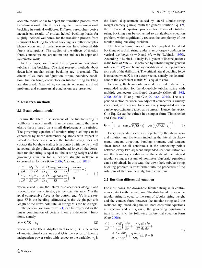
Because the lateral displacement of the tubular string in
wellbores is much smaller than the axial length, the linear
elastic theory based on a small displacement is satisfied.
The governing equation of tubular string buckling can be
expressed by linear differential equations with respect to
lateral displacements. When the tubular string does not
contact the borehole wall or is in contact with the well wall
at several single points, the distributed force on the down-
hole tubular string is equal to tubular string weight and the
governing equation for a inclined straight wellbore is
expressed as follows (Gao 2006; Gao and Liu 2013):
d4u
dz4þMT
EI
d3v
dz3þ d
dz
F�qzcosaEI
du
dz
� ��qsina
EI¼ 0
d4v
dz4�MT
EI
d3u
dz3þ d
dz
F�qzcosaEI
dv
dz
� �¼ 0
8>><>>:
; ð1Þ
where u and v are the lateral displacements along x and
y coordinates, respectively; z is the axial distance; F is the
axial compressive force at the bottom end; MT is the tor-
que; EI is the bending stiffness; q is the weight per unit
length of the down-hole tubular string; a is the hole angle.
The general solution of Eq. (1) can be expressed as the
linear combination of certain linearly independent func-
tions, namely
w ¼ GTXþ wg; ð2Þ
where w is the lateral displacement (u or v); X is the vector
of undetermined constants and G is the vector of linearly
independent power series with respect to the variable; wg is
the lateral displacement caused by lateral tubular string
weight (namely q sin a). With the general solution Eq. (2),
the differential equation problem for down-hole tubular
string buckling can be converted to an algebraic equation
problem, which significantly reduces the complexity of the
tubular string buckling problem.
The beam-column model has been applied to lateral
buckling of a drill string under a zero-torque condition in
vertical wellbores (a = 0 and MT = 0) (Lubinski 1950).
According to Lubinski’s analysis, a systemof linear equations
in the form ofMX ¼ 0 is obtained by substituting the general
solution Eq. (2) into boundary conditions at the top and bot-
tom ends of the drill string. The critical lateral buckling force
is obtained when X is not a zero vector, namely the determi-
nant of the coefficient matrixM is equal to zero.
Generally, the beam-column model is used to depict the
suspended section for the down-hole tubular string with
multiple connectors distributed discretely (Mitchell 1982,
2000, 2003a; Huang and Gao 2014a,b, 2015). The sus-
pended section between two adjacent connectors is usually
very short, so the axial force on every suspended section
can be approximately taken as a constant. Hence, the vector
G in Eq. (2) can be written in a simpler form (Timoshenko
and Gere 1963):
G ¼ 1 z sinffiffiffiffiffiffiffiffiffiffiffiF=EI
p� z
� �cos
ffiffiffiffiffiffiffiffiffiffiffiF=EI
p� z
� �h iT: ð3Þ
Every suspended section is depicted by the above gen-
eral solution and the terms including the lateral displace-
ment, tangent direction, bending moment, and tangent
shear force are all continuous at the connecting points
between every two adjacent suspended sections. Introduc-
ing the boundary conditions at the ends of the integral
tubular string, a system of nonlinear algebraic equations
can be obtained. In this way, the down-hole tubular string
buckling problem is transformed into the properties of the
solutions of the nonlinear algebraic equations.
2.2 Buckling differential equation
For most cases, the down-hole tubular string is in contin-
uous contact with the wellbore. The distributed force on the
tubular string is equal to the sum of tubular string weight
and the contact force between the tubular string and the
wellbore. By introducing the wellbore constraint equations
u ¼ rc cos h and v ¼ rc sin h, the governing equation is
transformed into the following differential equation form
(Gao 2006):
d4hdz4
� 6dhdz
� �2d2hdz2
þ 3MT
EI
dhdz
d2hdz2
þ
d
dz
F
EI
dhdz
� �þ q sin a
EIrcsin h ¼ 0
ð4Þ
444 Pet. Sci. (2015) 12:443–457
123

and the contact force on the tubular string is calculated by
the the following equation:
N ¼ EIrc 4d3hdz3
dhdz
þ 3d2hdz2
� �2
� dhdz
� �4" #
þ
MTrcdhdz
� �3
� d3hdz3
" #þ Frc
dhdz
� �2
þ q sin a cos h;
ð5Þ
where h is the angular displacement shown in Fig. 1; rc is
the radial clearance between the tubular string and the
wellbore; N is the compressive contact force on the tubular
string per unit length.
Different from the beam-column model expressed by
two variables u and v, there is only one variable h in the
buckling differential equation. However, it is difficult to
solve the buckling differential equation due to the existence
of nonlinear terms. If the friction force is introduced, the
axial force F is related to the contact force N, and the
complexity of the buckling differential equation is
increased a lot. Up to now, general analytical solutions for
the buckling differential equation Eq. (4) have not been
found. Sinusoidal buckling and helical buckling are con-
sidered to be two representative solutions for Eq. (4) at
present. It is generally accepted that a long tubular string
constrained in a wellbore goes through an initial straight
configuration, then sinusoidal buckling and later helical
buckling with an increase in the axial compressive force
from zero. These two buckling modes have been observed
in a lot of experiments.
Sinusoidal buckling means that the tubular string
behaves like a snaking curve along the lower side of the
inclined wellbore. The sinusoidal buckling solution is
usually expressed by
h ¼ A sin x � zð Þ; ð6Þ
where A is the amplitude and x is the angular velocity of
the angular displacement fluctuation. The critical load Fcrs
for the sinusoidal buckling can be obtained by analyzing
the stability of the approximate linear form of Eq. (4) (Gao
et al. 1998; Gao and Miska 2009). The relationship
between the amplitude A and the axial force F is calculated
by solving Eq. (4) with a perturbation method (Gao and
Miska 2009).
Helical buckling means that the down-hole tubular
string becomes a helix which spirals around the inner
surface of the wellbore. The helical buckling solution can
be expressed as follows:
h ¼ 2ppz or h ¼ 2p
pzþ A sin
2ppz
� �; ð7Þ
where p is the helix pitch; A is the fluctuation amplitude
caused by the tubular string weight. The analytical solution
for the parameter p ¼ 2pffiffiffiffiffiffiffiffiffiffiffiffiffi2EI=F
pis deduced from Eq. (4)
for a weightless tubular string without torque (Mitchell
1988; Gao 2006). The parameter A is approximately solved
with the perturbation method by assuming A to be a small
term (Liu 1999; Gao and Miska 2010a). The critical load
Fcrh which converts the sinusoidal buckling to helical
buckling is obtained when the contact force N between the
tubular string and the high side of the inclined wellbore is
equal to zero (Liu 1999).
2.3 Energy method
The energy method is another effective tool for us to study
down-hole tubular string buckling problems. Compared to
approximate solutions Eqs. (6) and (7) directly from the
buckling differential equation, the buckling solutions from
the energy method can be assumed more freely to depict
the buckling configuration. Substituting approximate
solutions such as Eqs. (6) or (7) into the total potential
energy expression and calculating its minimum value, the
buckling solutions can be determined. Meanwhile, the
energy method is better used to calculate the critical
buckling load and to analyze the stability of the post-
buckling configuration.
For the suspended section on which the tubular string is
not in contact with the wellbore, the total potential energy
of the tubular string in inclined wellbores is expressed as
the function of lateral displacements (Gao 2006):
P¼ Ub �XF �XM �Xq
¼ 1
2
ZL
z¼0
EIo2u
oz2
� �2
þ o2v
oz2
� �2" #
�Fou
oz
� �2
þ ov
oz
� �2" #(
�MT
ou
oz
o2v
oz2þ ov
oz
o2u
oz2
� �þ 2q sina rc � uð Þ
dz:
ð8Þ
For the continuous contact section on which the the
tubular string is in continuous contact with the wellbore,Fig. 1 Down-hole tubular string buckling in a inclined straight
wellbore
Pet. Sci. (2015) 12:443–457 445
123
the total potential energy is expressed as the function of
angular displacement:
P ¼ 1
2r2c
ZL
z¼0
EIdhdz
� �4
þ d2hdz2
� �2" #
� Fdhdz
� �2(
�MT
dhdz
� �3
þ 2q sin a 1� cos hð Þrc
)dz;
ð9Þ
where Ub is the elastic bending energy; XF is the virtual
work for axial force; XM is the virtual work for torque; and
Xq is the virtual work for tubular string weight.
To be specific, the amplitude A for sinusoidal buckling
is calculated by introducing h ¼ A sin x � zð Þ into the total
potential energy equation for the continuous section and
letting the total energy reach the minimum value oPoA
¼ 0.
With the critical stability condition o2PoA2 ¼ 0, the critical
load Fcrs is obtained (Liu 1999; Gao and Miska 2009),
which converts the initial straight configuration into sinu-
soidal buckling. Similar to the analysis in sinusoidal
buckling, the helical buckling pitch p for a weightless
tubular string is deduced by introducing h ¼ 2ppz into
Eq. (9) and letting oPop
¼ 0 (Lubinski and Althouse 1962).
For a tubular string with weight, the helical buckling
solution is h ¼ 2ppzþ A sin 2p
pz
�, which is more compli-
cated than that for the weightless tubular string, whereas
the solution process for the helical buckling fluctuation
amplitude A is similar. Different from the stability criterion
for sinusoidal buckling, the critical force Fcrs which con-
verts sinusoidal buckling to helical buckling is deduced by
letting DP ¼ 0, where DP means the difference of total
potential energy at the helical buckling and the initial
configuration stages (Chen et al. 1990; Wu 1992; Cunha
1995).
However, the above three research methods are usually
not isolated from each other. The combination of the three
methods can give a sophisticated description of the tubular
string deflection. For example, in the derivation of the
deflection curve on the transition section near the bound-
ary, the beam-column model is used to depict the sus-
pended section while the buckling differential equation to
depict the perturbed buckling section (Sorenson and
Cheatham 1986; Liu et al. 1999). Taking a down-hole
tubular string with two connectors on its two ends as
another example, the two portions of the tubular string near
the connectors are suspended, while the middle portion is
in continuous contact with the wellbore. Similar to the
analysis about boundary conditions, the suspended section
and the continuous contact section are, respectively,
depicted by the beam-column model and the bucking dif-
ferential equation. In addition, the relative angular
displacement between the two connectors is obtained when
the total potential energy of the down-hole tubular string
achieves the minimum value (Huang and Gao 2014b).
However, it is not an easy task for the simultaneous
applications of the three classic methods because of the
complicated solution process of the nonlinear algebraic
equation systems.
3 Effect of wellbore configuration
3.1 Vertical wellbore
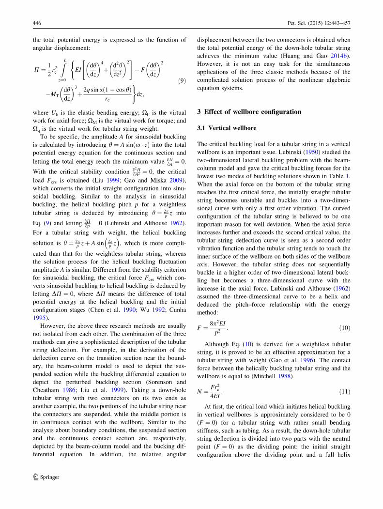
The critical buckling load for a tubular string in a vertical
wellbore is an important issue. Lubinski (1950) studied the
two-dimensional lateral buckling problem with the beam-
column model and gave the critical buckling forces for the
lowest two modes of buckling solutions shown in Table 1.
When the axial force on the bottom of the tubular string
reaches the first critical force, the initially straight tubular
string becomes unstable and buckles into a two-dimen-
sional curve with only a first order vibration. The curved
configuration of the tubular string is believed to be one
important reason for well deviation. When the axial force
increases further and exceeds the second critical value, the
tubular string deflection curve is seen as a second order
vibration function and the tubular string tends to touch the
inner surface of the wellbore on both sides of the wellbore
axis. However, the tubular string does not sequentially
buckle in a higher order of two-dimensional lateral buck-
ling but becomes a three-dimensional curve with the
increase in the axial force. Lubinski and Althouse (1962)
assumed the three-dimensional curve to be a helix and
deduced the pitch–force relationship with the energy
method:
F ¼ 8p2EIp2
: ð10Þ
Although Eq. (10) is derived for a weightless tubular
string, it is proved to be an effective approximation for a
tubular string with weight (Gao et al. 1996). The contact
force between the helically buckling tubular string and the
wellbore is equal to (Mitchell 1988)
N ¼ Fr2c4EI
: ð11Þ
At first, the critical load which initiates helical buckling
in vertical wellbores is approximately considered to be 0
(F ¼ 0) for a tubular string with rather small bending
stiffness, such as tubing. As a result, the down-hole tubular
string deflection is divided into two parts with the neutral
point (F ¼ 0) as the dividing point: the initial straight
configuration above the dividing point and a full helix
446 Pet. Sci. (2015) 12:443–457
123
depicted by Eq. (10) below the dividing point. Later, it was
realized that it is too conservative to take the neutral point
as the critical helical buckling force for the drill string. Wu
(1992) improved the calculation method for the critical
force between the three-dimensional sinusoidal buckling
and helical buckling in vertical wellbores with the energy
method shown in Table 1. In Wu’s analysis, the tubular
string buckles into a half-sine wave under the critical
sinusoidal buckling condition and into a pitch of helix
under the critical helical buckling condition.
Gao et al. (2002) and Gao (2006) pointed out that the
sinusoidal buckling is unstable but helical buckling is
stable in vertical wellbores with energy stability analysis
and deduced the critical helical buckling with the buckling
differential equation by letting the contact compressive
force be positive for a period of the helix. Although dif-
ferent methods are employed in Wu’s and Gao’s research,
their results for the critical helical buckling force are close
to each other.
Mitchell (1988) studied helical buckling by solving the
buckling differential equation numerically and proved that
Lubinski’s helical buckling model (Lubinski and Althouse
1962) was just an approximate result. Mitchell’s results
show that the pitch–force relationship expressed in
Eq. (10) becomes invalid to depict the tubular buckling
behavior near the neutral point because the tubular string
may be not in contact with the wellbore.
Previous studies indicate that a key but tough problem is
the depiction of the transition between the top suspended
section and the bottom helically buckled section. A com-
prehensive model should consider the two sections as a
whole: the top suspended section is depicted by the beam-
column model and the bottom continuous contact section is
depicted by the buckling differential equation. As a result,
the dividing point can be determined with continuity con-
ditions of axial displacement, slopes, bending moments and
shear contact force of the two sections. In addition, how the
two-dimensional lateral buckling turns to three-dimen-
sional helical buckling with an increase in axial force has
not been accurately described until now. A model for
depicting the whole transition process of buckling state
from initial vertical configuration, two-dimensional lateral
buckling to the final helical buckling should be proposed.
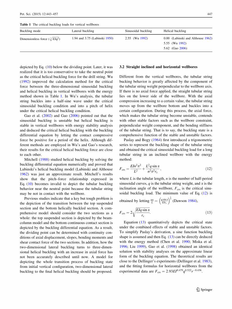
3.2 Straight inclined and horizontal wellbores
Different from the vertical wellbores, the tubular string
bucking behavior is greatly affected by the component of
the tubular string weight perpendicular to the wellbore axis.
If there is no axial force applied, the straight tubular string
lies on the lower side of the wellbore. With the axial
compression increasing to a certain value, the tubular string
moves up from the wellbore bottom and buckles into a
certain configuration. During this process, the axial force,
which makes the tubular string become unstable, contends
with other stable factors such as the wellbore constraint,
perpendicular weight component, and the bending stiffness
of the tubular string. That is to say, the buckling state is a
comprehensive function of the stable and unstable factors.
Paslay and Bogy (1964) first introduced a trigonometric
series to represent the buckling shape of the tubular string
and obtained the critical sinusoidal buckling load for a long
tubular string in an inclined wellbore with the energy
method:
Fcrs ¼EIn2p2
L2þ L2q sin a
n2p2rc; ð12Þ
where L is the tubular length, n is the number of half-period
sinusoidal curves, q is the tubular string weight, and a is theinclination angle of the wellbore, Fcrs is the critical sinu-
soidal buckling load. The minimum value of Eq. (12) is
obtained by letting npL¼ q sin a
EIrc
�14
(Dawson 1984),
Fcrs ¼ 2
ffiffiffiffiffiffiffiffiffiffiffiffiffiffiffiffiffiEIq sin a
rc
r: ð13Þ
Equation (13) quantitatively depicts the critical state
under the combined effects of stable and unstable factors.
To simplify Paslay’s derivation, a sine function buckling
shape is assumed and then Eq. (13) can be directly deduced
with the energy method (Chen et al. 1990; Miska et al.
1996; Liu 1999), Gao et al. (1998) obtained an identical
solution with stability analyses on the approximate linear
form of the buckling equation. The theoretical results are
close to the Dellinger’s experiments (Dellinger et al. 1983),
and the fitting formulas for horizontal wellbores from the
experimental data are Fcrs ¼ 2:93EI0:479q0:522r�0:436.
Table 1 The critical buckling loads for vertical wellbores
Buckling mode Lateral buckling Sinusoidal buckling Helical buckling
Dimensionless force (ffiffiffiffiffiffiffiffiffiEIq23
p) 1.94 and 3.75 (Lubinski 1950) 2.55 (Wu 1992) 0.00 (Lubinski and Althouse 1962)
5.55 (Wu 1992)
5.62 (Gao 2006)
Pet. Sci. (2015) 12:443–457 447
123
After the axial force exceeds the critical value, the
deflection curve of the tubular string can be approximately
expressed by Eq. (6), where A is the amplitude and x is the
angular velocity of the angular displacement fluctuation.
Different solving methods may lead to different solutions.
For example, Gao and Miska (2010a) obtained x ¼q sin aEIrc
�14
, A ¼ 4
ffiffiffiffiffiffiffib�111
qand b ¼ F
Fcrsby solving the buckling
differential equation with the perturbation method, while
Gao (2006) obtained x ¼ffiffiffiffiffiffiF2EI
qand A ¼
ffiffiffiffiffiffiffiffiffiffiffiffiffi8 b2�1ð Þ12b2�1
rwith the
energy method. In fact, these two results are rather close to
each other when the axial force approaches the critical
sinusoidal buckling force (b � 1).
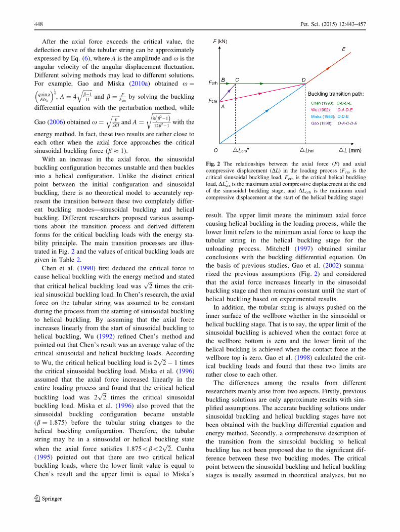
With an increase in the axial force, the sinusoidal
buckling configuration becomes unstable and then buckles
into a helical configuration. Unlike the distinct critical
point between the initial configuration and sinusoidal
buckling, there is no theoretical model to accurately rep-
resent the transition between these two completely differ-
ent buckling modes—sinusoidal buckling and helical
buckling. Different researchers proposed various assump-
tions about the transition process and derived different
forms for the critical buckling loads with the energy sta-
bility principle. The main transition processes are illus-
trated in Fig. 2 and the values of critical buckling loads are
given in Table 2.
Chen et al. (1990) first deduced the critical force to
cause helical buckling with the energy method and stated
that critical helical buckling load wasffiffiffi2
ptimes the crit-
ical sinusoidal buckling load. In Chen’s research, the axial
force on the tubular string was assumed to be constant
during the process from the starting of sinusoidal buckling
to helical buckling. By assuming that the axial force
increases linearly from the start of sinusoidal buckling to
helical buckling, Wu (1992) refined Chen’s method and
pointed out that Chen’s result was an average value of the
critical sinusoidal and helical buckling loads. According
to Wu, the critical helical buckling load is 2ffiffiffi2
p� 1 times
the critical sinusoidal buckling load. Miska et al. (1996)
assumed that the axial force increased linearly in the
entire loading process and found that the critical helical
buckling load was 2ffiffiffi2
ptimes the critical sinusoidal
buckling load. Miska et al. (1996) also proved that the
sinusoidal buckling configuration became unstable
(b ¼ 1:875) before the tubular string changes to the
helical buckling configuration. Therefore, the tubular
string may be in a sinusoidal or helical buckling state
when the axial force satisfies 1:875\b\2ffiffiffi2
p. Cunha
(1995) pointed out that there are two critical helical
buckling loads, where the lower limit value is equal to
Chen’s result and the upper limit is equal to Miska’s
result. The upper limit means the minimum axial force
causing helical buckling in the loading process, while the
lower limit refers to the minimum axial force to keep the
tubular string in the helical buckling stage for the
unloading process. Mitchell (1997) obtained similar
conclusions with the buckling differential equation. On
the basis of previous studies, Gao et al. (2002) summa-
rized the previous assumptions (Fig. 2) and considered
that the axial force increases linearly in the sinusoidal
buckling stage and then remains constant until the start of
helical buckling based on experimental results.
In addition, the tubular string is always pushed on the
inner surface of the wellbore whether in the sinusoidal or
helical buckling stage. That is to say, the upper limit of the
sinusoidal buckling is achieved when the contact force at
the wellbore bottom is zero and the lower limit of the
helical buckling is achieved when the contact force at the
wellbore top is zero. Gao et al. (1998) calculated the crit-
ical buckling loads and found that these two limits are
rather close to each other.
The differences among the results from different
researchers mainly arise from two aspects. Firstly, previous
buckling solutions are only approximate results with sim-
plified assumptions. The accurate buckling solutions under
sinusoidal buckling and helical buckling stages have not
been obtained with the buckling differential equation and
energy method. Secondly, a comprehensive description of
the transition from the sinusoidal buckling to helical
buckling has not been proposed due to the significant dif-
ference between these two buckling modes. The critical
point between the sinusoidal buckling and helical buckling
stages is usually assumed in theoretical analyses, but no
Fig. 2 The relationships between the axial force (F) and axial
compressive displacement (DL) in the loading process (Fcrs is the
critical sinusoidal buckling load, Fcrh is the critical helical buckling
load, DLcrs* is the maximum axial compressive displacement at the end
of the sinusoidal buckling stage, and DLcrh is the minimum axial
compressive displacement at the start of the helical buckling stage)
448 Pet. Sci. (2015) 12:443–457
123
distinct dividing point is found in experiments. Therefore,
sophisticated description of the buckling state transition
and accurate buckling solutions under these two buckling
modes still needs an in-depth research.
Previous studies assumed the radial deflection of the
tubular string was fixed on the borehole wall and derived
the pitch–force relationship (Eq. (10)) with the energy
method (Chen et al. 1990; Miska et al. 1996). Cheatham
(1984) removed the radial constraint from the wellbore in
the energy method and proposed another new pitch–force
relationship in the helical buckling stage:
F ¼ 4p2EIp2
: ð14Þ
Cheatham pointed out that Eqs. (10) and (14) are,
respectively, applicable for the loading and unloading
processes. In the loading process, the pitch of the helix is
variable but the tubular string is constrained by the well-
bore. However, in the unloading process, the tubular string
tends to lose contact with the wellbore but the pitch of the
helix remains constant. Huang et al. (2015a) verified
Cheatham’s results from the view of the buckling differ-
ential equation and further pointed out that the contact
force reaches its maximum value when Eq. (10) is satisfied
and its minimum value when Eq. (14) is satisfied.
Gao et al. (1998) pointed out that the tubular string
weight has an turbulent effect on the helix configuration,
and a more accurate buckling solution should be expressed
by
h ¼ 2ppzþ A sin
2ppz
� �: ð15Þ
The perturbation magnitude A ¼ � 45b2
is obtained by
solving the buckling differential equation (Gao et al. 1998)
and using the energy method (Gao 2006). Mitchell (2002a,
b) used the Jacobi elliptic functions to solve the buckling
differential equation and obtained the exact analytical
helical buckling solution as follows:
h ¼ 4 sin�1 sn
ffiffiffiffiffiffiffiffiffiffiffiffiffiffiffiffiffiffiffiffiffiffiffi25þ
ffiffiffiffiffi51
pb
50ffiffiffiffiffi51
pb
s� 2pzp
;50
25þffiffiffiffiffi51
pb
!" #:
ð16Þ
Meanwhile, Mitchell (2002a,b) found another new
buckling solution in which the tubular string buckles into a
periodically reversing curve which oscillates with a large
angular amplitude about the top of the wellbore rather than
the bottom of the wellbore. Huang et al. (2015a) further
proved that sinusoidal buckling and helical buckling are
just two special periodical solutions of the buckling dif-
ferential equation.
The effect of tubular string buckling on bending moment,
axial compressive displacement, and contact force is also an
important issue. Table 3 lists the values of these three fac-
tors in the sinusoidal buckling and helical buckling stages.
The bending moment from sinusoidal buckling can be
neglected, while bending moment from helical buckling is
significant especially under a large axial force with a big
radial clearance. Because the axial compressive displace-
ment in the helical buckling stage is far larger than that in
the sinusoidal buckling stage, the transition from sinusoidal
buckling to helical buckling includes a section where the
tubular string is continuously shortened with almost no
increase in the axial compression. This phenomenon has
been observed in buckling experiments (Salies 1994; Zou
2002) and now it has been introduced as an important
assumption to calculate the critical helical buckling loads.
The effect of the additional contact force from sinu-
soidal buckling is usually small for the length of the tubular
string in the sinusoidal buckling stage is quite limited
(Fcrs �F\Fcrh). However, the contact force increases
significantly in the helical buckling stage (F�Fcrh) due to
the quadric relationship between the contact force and axial
compressive load and it can seriously restrict the axial
force transfer when the friction force effect is taken into
consideration.
3.3 Curved wellbore
Experiments (McCann and Suryanarayana 1994; Salies
1994) have shown that the build wellbore curvature has a
stabilizing effect on tubular string buckling. The tubular
string may have been in ‘‘lock-up’’ or yielded while the
tubular string does not enter the buckling state in the build
section (Kyllingstad 1995).
Table 2 The critical axial forces for different buckling modes
Researchers Sinusoidal buckling (F/Fcrs) Sinusoidal or helical buckling (F/Fcrs) Helical buckling (F/Fcrs)
Chen et al. (1990) 1;ffiffiffi2
p� /
ffiffiffi2
p; 1
� Wu (1992) 1; 2
ffiffiffi2
p� 1
� / 2
ffiffiffi2
p� 1; 1
� Miska et al. (1996) 1; 1:875½ � 1:875; 2
ffiffiffi2
p� 2ffiffiffi2
p; 1
� Cunha (1995), Mitchell (1997) 1;
ffiffiffi2
p� ffiffiffi2
p; 2
ffiffiffi2
p� 2ffiffiffi2
p; 1
� Gao et al. (1998) 1; 1:401½ � / 1:401; 1½ �
Pet. Sci. (2015) 12:443–457 449
123

The first theoretical research into the critical buckling
loads in a curved wellbore was to convert the buckling
problem in a curved wellbore into the equivalent buckling
problem in an inclined wellbore. Considering that the
tubular weight component perpendicular to the wellbore
axis is equal to the contact force in the unbuckling state in
an inclined wellbore, the critical buckling load can be
expressed by (He and Kyllingstad 1995).
Fcr ¼ b
ffiffiffiffiffiffiffiffiffiffiffiffiffiffiffi4EI � N
rc
r; ð17Þ
where b ¼ 1 for Paslay’s sinusoidal buckling and b ¼ffiffiffi2
p
for the Chen’s helical buckling. Here, Eq. (17) is extended
to the curved wellbore case, and the buckling load can be
obtained by substituting the following contact force into a
build section:
N ¼ Fcr
Rþ q sin a; ð18Þ
where R is the curvature radius of the wellbore, q is the
weight per unit length of the tubular string, and a is the
inclination angle.
Wu and Juvkam-Wold (1995a) deduced the critical
buckling loads in build and drop-off wellbore sections
shown in Tables 4 and 5 with the energy method, in which
the lateral component of tubular string weight and axial
force was considered to do negative work. Wu’s results
show that the critical buckling loads in curved wellbores
are usually larger than that in straight wellbores, except
that the critical buckling loads become smaller in drop-off
wellbores with small curvature. Later, Qui et al. (1998)
obtained the critical buckling loads in which only the lat-
eral component of tubular string weight was considered to
do negative work and found that the sinusoidal buckling
has become unstable before the tubular string enters the
helical buckling stage. Kyllingstad (1995) pointed out that
there is an overlapping section for two buckling states
which acts as a barrier for buckling mode conversion.
Mitchell (1999b) obtained Miska’s critical sinusoidal
buckling loads by both solving the buckling differential
equation and using energy stability analysis, and resolved
the conflict between the Miska and Wu’s results. Mitchell
(1999b) pointed out that the lateral tubular string weight
which appears to be part of the contact force can be
neglected in Wu’s studies as no work is done by the contact
force. Liu (1999) solved the buckling differential equation
with the Galerkin method and derived the critical helical
buckling loads in build and drop-off wellbore sections by
letting the minimum contact force on the tubular string be
0. Liu’s results indicate that the up-limit value of the
sinusoidal buckling is rather close to the critical helical
buckling load.
Similar to the inclined wellbore case, the sinusoidal and
helical buckling solutions of the tubular string in a curved
wellbore can be expressed by h ¼ A sin x � zð Þ and
h ¼ 2ppzþ B sin 2p
pz
�, in which the variable z is referred to
the arc-length of the wellbore axis. The relevant parameters
are calculated by A ¼ffiffiffiffiffiffiffiffiffiffiffi8 1�kð Þ12�k
q, p ¼
ffiffiffiffiffiffiF2EI
qand B ¼ � 1
5k,
where k ¼ Fq sin aR þ 1 �
� 4EIq sin arc
.F2 (Liu 1999).
The previous studies are mainly focused on build and
drop-off wellbore sections in the vertical inclination plane.
However, previous bucking models may not be applicable
for three-dimensional wellbores of which both the incli-
nation and azimuth angles change simultaneously in com-
plex-structure wells. Therefore, a tubular string buckling
model for arbitrary wellbores is needed.
4 Effect of other factors
4.1 Torque
Miska and Cunha (1995) proposed the critical helical
buckling torque for a tubular string without axial force,
Tcrh ¼ 2:087
ffiffiffiffiffiffiffiffiffiffiffiffiffiffiffiffiffiffiffiffiffiffiffiEIð Þ3q sin a
r
4
s; ð19Þ
and then the pitch of the helix is equal to
p ¼ 8EIp3T
: ð20Þ
Table 3 Relevant parameters in the post sinusoidal and helical buckling stages
Buckling mode Maximum bending moment (M) Axial compressive displacement (DL/L) Contact force (N)
Sinusoidal 0:6302F0:08 F � Fcrsð Þ0:92rc(Mitchell 1999a)
�0:7285r2c4EI
F0:08 F � Fcrsð Þ0:92(Mitchell 1999a)
�0:0843r2cF
4EI(Liu 1999)
q sin a (Mitchell 1999a)
q sin aþ rF2
8EI(Wu 1995)
Helical 0:5Frc � r2cF
4EI
rF2
4EIþ q sin a (Mitchell 1999a)
rF2
4EI(Liu 1999)
450 Pet. Sci. (2015) 12:443–457
123
However, the tubular string usually has yielded before
torque reaches the critical value Eq. (19).
The critical helical buckling conditions while consider-
ing the effects of axial force, torque, and tubular string
weight are shown in Table 6. Miska and Cunha (1995)
derived the critical helical buckling load and pitch of the
helix with the energy method. Later, He et al. (1995)
treated the torque as a perturbation and obtained the
approximate results for Miska’s model. Wu (1997)
assumed that there is only one period of helix when the
axial force reaches its critical value and derived the critical
buckling loads with the energy method. Their studies
simultaneously show that the torque decreases the critical
helical buckling load and pitch but increases the contact
force. However, the pitch of the helix may be increased if
the direction of the helix is opposite to that of the applied
torque and torque has been proved to have no effect on
sinusoidal buckling (Gao 2006). Paslay’s experimental
studies (Paslay 1994) indicated that the effect of torque on
the critical helical buckling load was limited usually no
more than 10 %.
Not only does torque affect the helical buckling con-
figuration, but also helical buckling can also induce torque
in turn. If a tubular string without torque at initial state is
compressed axially and the two ends of the tubular string
are constrained with no relative rotation, the induced tor-
que due to helical buckling is equal to (Mitchell 2004)
Tind ¼ �Fr2c2
ffiffiffiffiffiffiffiffiF
2EI
r: ð21Þ
Mitchell (2004) pointed out that the induced torque may
exceed the makeup torque for large radial clearance. Gao
(2006) supplemented Mitchell’s theory and referred to the
induced torque as an incentive for the helix direction
reversal observed in experiments (Salies 1994).
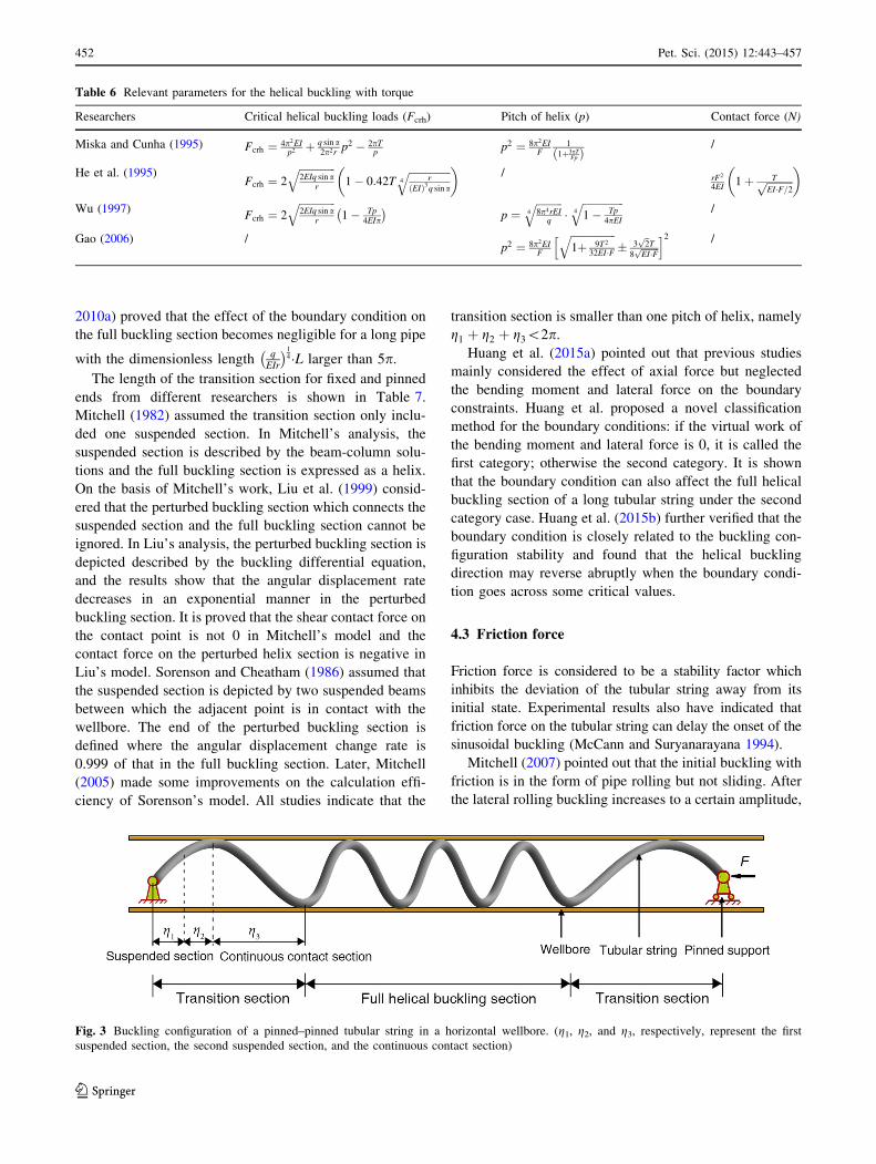
4.2 Boundary conditions
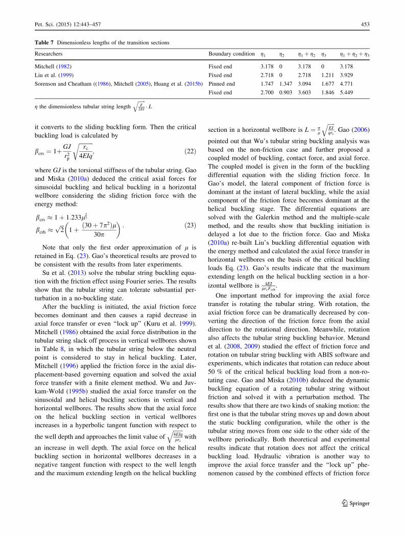
For a long pinned–pinned or clamped–clamped tubular
string, the buckling configuration is divided into two parts:
the transition section adjacent to the boundary condition
and the full buckling section in the middle shown in Fig. 3
(Huang et al. 2015b). The transition section is further
divided into suspended and perturbed buckling sections.
For the suspended section, the tubular string loses contact
with the wellbore due to the support of the boundary
condition. For the full buckling section, the tubular string
buckles into a sinusoidal or helical configuration. The
perturbed buckling section, on which the tubular string is in
continuous contact with the wellbore, is seen as the tran-
sition from no contact to full buckling section.
Wu and Juvkam-Wold (1995a) pointed out that if a
tubular string has 3.5 or more pitches of helix, the transi-
tion section can be neglected. Gao and Miska (2009,
Table 4 Critical buckling loads for build-up wellbores
Researchers Critical sinusoidal buckling (Fcrs) Critical helical buckling (Fcrh)
He et al. (1995)2EIRrc
ffiffiffiffiffiffiffiffiffiffiffiffiffiffiffiffiffiffiffiffiffiffiffiffiffiffiffiffiffiffiffiffiffiffiffiffi1þ
ffiffiffiffiffiffiffiffiffiffiffiffiffiffiffiffiffiffiffiffiffiffiffi1þ R2rcq sin a
EI
qr4EIRrc
ffiffiffiffiffiffiffiffiffiffiffiffiffiffiffiffiffiffiffiffiffiffiffiffiffiffiffiffiffiffiffiffiffiffiffiffi1þ
ffiffiffiffiffiffiffiffiffiffiffiffiffiffiffiffiffiffiffiffiffiffiffi1þ R2rcq sin a
2EI
qr
Wu and Juvkam-Wold (1995a)4EIRrc
ffiffiffiffiffiffiffiffiffiffiffiffiffiffiffiffiffiffiffiffiffiffiffiffiffiffiffiffiffiffiffiffiffiffiffiffi1þ
ffiffiffiffiffiffiffiffiffiffiffiffiffiffiffiffiffiffiffiffiffiffiffi1þ R2rcq sin a
4EI
qr12EIRrc
ffiffiffiffiffiffiffiffiffiffiffiffiffiffiffiffiffiffiffiffiffiffiffiffiffiffiffiffiffiffiffiffiffiffiffiffi1þ
ffiffiffiffiffiffiffiffiffiffiffiffiffiffiffiffiffiffiffiffiffiffiffi1þ R2rcq sin a
8EI
qr
Qui et al. (1998)2EIRrc
ffiffiffiffiffiffiffiffiffiffiffiffiffiffiffiffiffiffiffiffiffiffiffiffiffiffiffiffiffiffiffiffiffiffiffiffi1þ
ffiffiffiffiffiffiffiffiffiffiffiffiffiffiffiffiffiffiffiffiffiffiffi1þ R2rcq sin a
EI
qr, 2:532EI
Rrc
ffiffiffiffiffiffiffiffiffiffiffiffiffiffiffiffiffiffiffiffiffiffiffiffiffiffiffiffiffiffiffiffiffiffiffiffi1þ
ffiffiffiffiffiffiffiffiffiffiffiffiffiffiffiffiffiffiffiffiffiffiffi1þ R2rcq sin a
3:52EI
qr8EIRrc
ffiffiffiffiffiffiffiffiffiffiffiffiffiffiffiffiffiffiffiffiffiffiffiffiffiffiffiffiffiffiffiffiffiffiffiffi1þ
ffiffiffiffiffiffiffiffiffiffiffiffiffiffiffiffiffiffiffiffiffiffiffi1þ R2rcq sin a
2EI
qr
Liu (1999)2EIRrc
ffiffiffiffiffiffiffiffiffiffiffiffiffiffiffiffiffiffiffiffiffiffiffiffiffiffiffiffiffiffiffiffiffiffiffiffi1þ
ffiffiffiffiffiffiffiffiffiffiffiffiffiffiffiffiffiffiffiffiffiffiffi1þ R2rcq sin a
EI
qr3:77EIRrc
ffiffiffiffiffiffiffiffiffiffiffiffiffiffiffiffiffiffiffiffiffiffiffiffiffiffiffiffiffiffiffiffiffiffiffiffiffiffiffiffiffiffi1þ
ffiffiffiffiffiffiffiffiffiffiffiffiffiffiffiffiffiffiffiffiffiffiffiffiffiffiffiffiffi1þ 0:53R2rcq sin a
EI
qr
Table 5 Critical buckling loads for drop-off wellbores
Researchers Critical sinusoidal buckling (Fcrs) Critical helical buckling (Fcrh)
Wu and Juvkam-Wold (1995a)4EIRrc
ffiffiffiffiffiffiffiffiffiffiffiffiffiffiffiffiffiffiffiffiffiffiffiffiffiffiffiffiffiffiffiffiffiffiffiffi1þ
ffiffiffiffiffiffiffiffiffiffiffiffiffiffiffiffiffiffiffiffiffiffiffi1� R2rcq sin a
4EI
qr(large curvature)
4EIRrc
ffiffiffiffiffiffiffiffiffiffiffiffiffiffiffiffiffiffiffiffiffiffiffiffiffiffiffiffiffiffiffiffiffiffiffiffiffiffiffiffi�1þ
ffiffiffiffiffiffiffiffiffiffiffiffiffiffiffiffiffiffiffiffiffiffiffi1þ R2rcq sin a
4EI
qr(small curvature)
12EIRrc
ffiffiffiffiffiffiffiffiffiffiffiffiffiffiffiffiffiffiffiffiffiffiffiffiffiffiffiffiffiffiffiffiffiffiffiffi1þ
ffiffiffiffiffiffiffiffiffiffiffiffiffiffiffiffiffiffiffiffiffiffiffi1� R2rcq sin a
8EI
qr(large curvature)
12EIRrc
ffiffiffiffiffiffiffiffiffiffiffiffiffiffiffiffiffiffiffiffiffiffiffiffiffiffiffiffiffiffiffiffiffiffiffiffiffiffiffiffi�1þ
ffiffiffiffiffiffiffiffiffiffiffiffiffiffiffiffiffiffiffiffiffiffiffi1þ R2rcq sin a
8EI
qr(small curvature)
Liu (1999)2EIRrc
ffiffiffiffiffiffiffiffiffiffiffiffiffiffiffiffiffiffiffiffiffiffiffiffiffiffiffiffiffiffiffiffiffiffiffiffi1þ
ffiffiffiffiffiffiffiffiffiffiffiffiffiffiffiffiffiffiffiffiffiffiffi1� R2rcq sin a
EI
qr3:77EIRrc
ffiffiffiffiffiffiffiffiffiffiffiffiffiffiffiffiffiffiffiffiffiffiffiffiffiffiffiffiffiffiffiffiffiffiffiffiffiffiffiffiffiffi1þ
ffiffiffiffiffiffiffiffiffiffiffiffiffiffiffiffiffiffiffiffiffiffiffiffiffiffiffiffiffi1� 0:53R2rcq sin a
EI
qr
Pet. Sci. (2015) 12:443–457 451
123
2010a) proved that the effect of the boundary condition on
the full buckling section becomes negligible for a long pipe
with the dimensionless length qEIr
� �14�L larger than 5p.
The length of the transition section for fixed and pinned
ends from different researchers is shown in Table 7.
Mitchell (1982) assumed the transition section only inclu-
ded one suspended section. In Mitchell’s analysis, the
suspended section is described by the beam-column solu-
tions and the full buckling section is expressed as a helix.
On the basis of Mitchell’s work, Liu et al. (1999) consid-
ered that the perturbed buckling section which connects the
suspended section and the full buckling section cannot be
ignored. In Liu’s analysis, the perturbed buckling section is
depicted described by the buckling differential equation,
and the results show that the angular displacement rate
decreases in an exponential manner in the perturbed
buckling section. It is proved that the shear contact force on
the contact point is not 0 in Mitchell’s model and the
contact force on the perturbed helix section is negative in
Liu’s model. Sorenson and Cheatham (1986) assumed that
the suspended section is depicted by two suspended beams
between which the adjacent point is in contact with the
wellbore. The end of the perturbed buckling section is
defined where the angular displacement change rate is
0.999 of that in the full buckling section. Later, Mitchell
(2005) made some improvements on the calculation effi-
ciency of Sorenson’s model. All studies indicate that the
transition section is smaller than one pitch of helix, namely
g1 þ g2 þ g3\2p.Huang et al. (2015a) pointed out that previous studies
mainly considered the effect of axial force but neglected
the bending moment and lateral force on the boundary
constraints. Huang et al. proposed a novel classification
method for the boundary conditions: if the virtual work of
the bending moment and lateral force is 0, it is called the
first category; otherwise the second category. It is shown
that the boundary condition can also affect the full helical
buckling section of a long tubular string under the second
category case. Huang et al. (2015b) further verified that the
boundary condition is closely related to the buckling con-
figuration stability and found that the helical buckling
direction may reverse abruptly when the boundary condi-
tion goes across some critical values.
4.3 Friction force
Friction force is considered to be a stability factor which
inhibits the deviation of the tubular string away from its
initial state. Experimental results also have indicated that
friction force on the tubular string can delay the onset of the
sinusoidal buckling (McCann and Suryanarayana 1994).
Mitchell (2007) pointed out that the initial buckling with
friction is in the form of pipe rolling but not sliding. After
the lateral rolling buckling increases to a certain amplitude,
Fig. 3 Buckling configuration of a pinned–pinned tubular string in a horizontal wellbore. (g1, g2, and g3, respectively, represent the first
suspended section, the second suspended section, and the continuous contact section)
Table 6 Relevant parameters for the helical buckling with torque
Researchers Critical helical buckling loads (Fcrh) Pitch of helix (p) Contact force (N)
Miska and Cunha (1995) Fcrh ¼ 4p2EIp2
þ q sin a2p2r p
2 � 2pTp
p2 ¼ 8p2EIF
1
1þ3pTFpð Þ
/
He et al. (1995)Fcrh ¼ 2
ffiffiffiffiffiffiffiffiffiffiffiffiffiffi2EIq sin a
r
q1� 0:42T
ffiffiffiffiffiffiffiffiffiffiffiffiffiffiffiffir
EIð Þ3q sin a4
q� �/
rF2
4EI1þ Tffiffiffiffiffiffiffiffiffiffi
EI�F=2p
� �
Wu (1997)Fcrh ¼ 2
ffiffiffiffiffiffiffiffiffiffiffiffiffiffi2EIq sin a
r
q1� Tp
4EIp
� �p ¼
ffiffiffiffiffiffiffiffiffiffi8p4rEI
q4
q�ffiffiffiffiffiffiffiffiffiffiffiffiffiffiffiffi1� Tp
4pEI4
q/
Gao (2006) /p2 ¼ 8p2EI
F
ffiffiffiffiffiffiffiffiffiffiffiffiffiffiffiffiffi1þ 9T2
32EI�F
q� 3
ffiffi2
pT
8ffiffiffiffiffiffiffiEI�F
ph i2 /
452 Pet. Sci. (2015) 12:443–457
123
it converts to the sliding buckling form. Then the critical
buckling load is calculated by
bcrs ¼ 1þGJ
r2p
ffiffiffiffiffiffiffiffiffiffirc
4EIq
r; ð22Þ
where GJ is the torsional stiffness of the tubular string. Gao
and Miska (2010a) deduced the critical axial forces for
sinusoidal buckling and helical buckling in a horizontal
wellbore considering the sliding friction force with the
energy method:
bcrs � 1þ 1:233l23
bcrh �ffiffiffi2
p1þ 30þ 7p2ð Þl
30p
� �: ð23Þ
Note that only the first order approximation of l is
retained in Eq. (23). Gao’s theoretical results are proved to
be consistent with the results from later experiments.
Su et al. (2013) solve the tubular string buckling equa-
tion with the friction effect using Fourier series. The results
show that the tubular string can tolerate substantial per-
turbation in a no-buckling state.
After the buckling is initiated, the axial friction force
becomes dominant and then causes a rapid decrease in
axial force transfer or even ‘‘lock up’’ (Kuru et al. 1999).
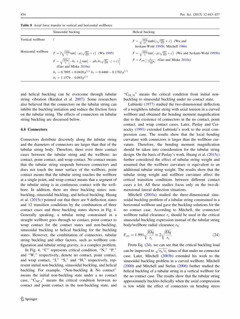
Mitchell (1986) obtained the axial force distribution in the
tubular string slack off process in vertical wellbores shown
in Table 8, in which the tubular string below the neutral
point is considered to stay in helical buckling. Later,
Mitchell (1996) applied the friction force in the axial dis-
placement-based governing equation and solved the axial
force transfer with a finite element method. Wu and Juv-
kam-Wold (1995b) studied the axial force transfer on the
sinusoidal and helical buckling sections in vertical and
horizontal wellbores. The results show that the axial force
on the helical buckling section in vertical wellbores
increases in a hyperbolic tangent function with respect to
the well depth and approaches the limit value offfiffiffiffiffiffiffi4EIqlrc
qwith
an increase in well depth. The axial force on the helical
buckling section in horizontal wellbores decreases in a
negative tangent function with respect to the well length
and the maximum extending length on the helical buckling
section in a horizontal wellbore is L ¼ pl
ffiffiffiffiffiEIqrc
q. Gao (2006)
pointed out that Wu’s tubular string buckling analysis was
based on the non-friction case and further proposed a
coupled model of buckling, contact force, and axial force.
The coupled model is given in the form of the buckling
differential equation with the sliding friction force. In
Gao’s model, the lateral component of friction force is
dominant at the instant of lateral buckling, while the axial
component of the friction force becomes dominant at the
helical buckling stage. The differential equations are
solved with the Galerkin method and the multiple-scale
method, and the results show that buckling initiation is
delayed a lot due to the friction force. Gao and Miska
(2010a) re-built Liu’s buckling differential equation with
the energy method and calculated the axial force transfer in
horizontal wellbores on the basis of the critical buckling
loads Eq. (23). Gao’s results indicate that the maximum
extending length on the helical buckling section in a hor-
izontal wellbore is 4EIlrcFcrh
.
One important method for improving the axial force
transfer is rotating the tubular string. With rotation, the
axial friction force can be dramatically decreased by con-
verting the direction of the friction force from the axial
direction to the rotational direction. Meanwhile, rotation
also affects the tubular string buckling behavior. Menand
et al. (2008, 2009) studied the effect of friction force and
rotation on tubular string buckling with ABIS software and
experiments, which indicates that rotation can reduce about
50 % of the critical helical buckling load from a non-ro-
tating case. Gao and Miska (2010b) deduced the dynamic
buckling equation of a rotating tubular string without
friction and solved it with a perturbation method. The
results show that there are two kinds of snaking motion: the
first one is that the tubular string moves up and down about
the static buckling configuration, while the other is the
tubular string moves from one side to the other side of the
wellbore periodically. Both theoretical and experimental
results indicate that rotation does not affect the critical
buckling load. Hydraulic vibration is another way to
improve the axial force transfer and the ‘‘lock up’’ phe-
nomenon caused by the combined effects of friction force
Table 7 Dimensionless lengths of the transition sections
Researchers Boundary condition g1 g2 g1 þ g2 g3 g1 þ g2 þ g3
Mitchell (1982) Fixed end 3.178 0 3.178 0 3.178
Liu et al. (1999) Fixed end 2.718 0 2.718 1.211 3.929
Sorenson and Cheatham ((1986), Mitchell (2005), Huang et al. (2015b) Pinned end 1.747 1.347 3.094 1.677 4.771
Fixed end 2.700 0.903 3.603 1.846 5.449
g the dimensionless tubular string lengthffiffiffiffiffiffiF2EI
q� L
Pet. Sci. (2015) 12:443–457 453
123
and helical buckling can be overcome through tubular
string vibration (Barakat et al. 2007). Some researchers
also believed that the connectors on the tubular string can
inhibit the buckling initiation and reduce the friction force
on the tubular string. The effects of connectors on tubular
string buckling are discussed below.
4.4 Connectors
Connectors distribute discretely along the tubular string
and the diameters of connectors are larger than that of the
tubular string body. Therefore, there exist three contact
cases between the tubular string and the wellbore: no
contact, point contact, and wrap contact. No contact means
that the tubular string suspends between connectors and
does not touch the inner surface of the wellbore, point
contact means that the tubular string touches the wellbore
at a single point, and wrap contact means that a segment of
the tubular string is in continuous contact with the well-
bore. In addition, there are three buckling states: non-
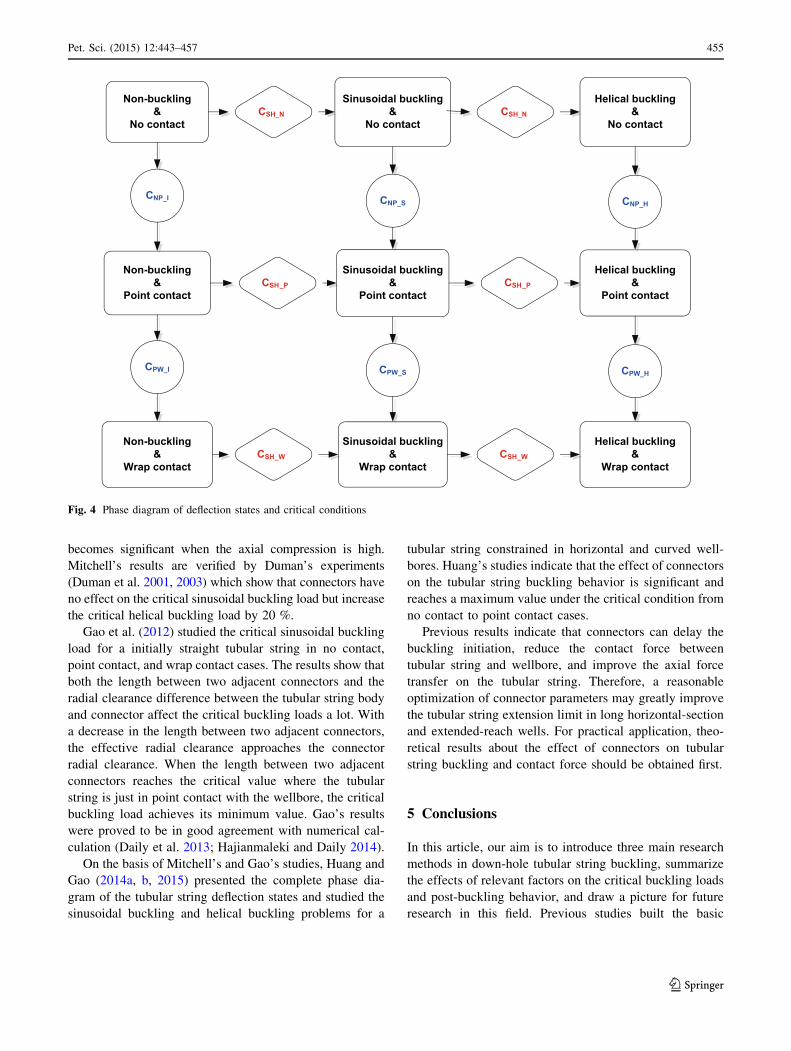
buckling, sinusoidal buckling, and helical buckling. Huang
et al. (2015c) pointed out that there are 9 deflection states
and 12 transition conditions by the combination of three
contact cases and three buckling states shown in Fig. 4.
Generally speaking, a tubular string constrained in a
straight wellbore goes through no contact, point contact to
wrap contact for the contact states and non-buckling,
sinusoidal buckling to helical buckling for the buckling
states. However, the combination of connectors, tubular
string buckling and other factors, such as wellbore con-
figuration and tubular string gravity, is a complex problem.
In Fig. 4, ‘‘C’’ represents critical condition, ‘‘N,’’ ‘‘P,’’
and ‘‘W,’’ respectively, denote no contact, point contact,
and wrap contact, ‘‘I,’’ ‘‘S,’’ and ‘‘H,’’ respectively, rep-
resent initial non-buckling, sinusoidal buckling, and helical
buckling. For example, ‘‘Non-buckling & No contact’’
means the initial non-buckling state under a no contact
case, ‘‘CNP_I’’ means the critical condition between no
contact and point contact in the non-buckling state, and
‘‘CIS_N’’ means the critical condition from initial non-
buckling to sinusoidal buckling under no contact state.
Lubinski (1977) studied the two-dimensional deflection
of a weightless tubular string with axial tension in a curved
wellbore and obtained the bending moment magnification
due to the existence of connectors in the no contact, point
contact, and wrap contact cases. Later, Paslay and Cer-
nocky (1991) extended Lubinski’s work to the axial com-
pression case. The results show that the local bending
curvature with connectors is larger than the wellbore cur-
vature. Therefore, the bending moment magnification
should be taken into consideration for the tubular string
design. On the basis of Paslay’s work, Huang et al. (2015c)
further considered the effect of tubular string weight and
assumed that the wellbore curvature is equivalent to an
additional tubular string weight. The results show that the
tubular string weight and wellbore curvature affect the
critical transition conditions between different contact
cases a lot. All these studies focus only on the two-di-
mensional lateral deflection situations.
Mitchell (2003a) studied the three-dimensional sinu-
soidal buckling problem of a tubular string constrained in a
horizontal wellbore and gave the buckling solutions for the
no contact case. According to Mitchell, the connector/
wellbore radial clearance rc should be used in the critical
sinusoidal buckling expression instead of the tubular string
body/wellbore radial clearance rb:
Fcrs ¼ 1:991
ffiffiffiffiffiffiffiEIq
rc
r� 2
ffiffiffiffiffiffiffiEIq
rc
r: ð24Þ
From Eq. (24), we can see that the critical buckling load
can be improved toffiffiffiffiffiffiffiffiffiffirb=rc
ptimes of that under no connector
case. Later, Mitchell (2003b) extended his work to the
sinusoidal buckling problem in a curved wellbore. Mitchell
(2000) and Mitchell and Stefan (2006) further studied the
helical buckling of a tubular string in a vertical wellbore for
the no contact case. The results show that the tubular string
approximately buckles helically when the axial compression
is low while the effect of connectors on bending stress
Table 8 Axial force transfer in vertical and horizontal wellbores
Sinusoidal bucking Helical bucking
Vertical wellbore / F ¼ffiffiffiffiffiffiffi4EIqlrc
qtanh z
ffiffiffiffiffiffiffilqrc4EI
pþ c
� �(Wu and
Juvkam-Wold 1995b; Mitchell 1986)
Horizontal wellboreF ¼ 2
ffiffiffiffiffiffiffi2EIqrc
qtan �lz
ffiffiffiffiffiffiqrc8EI
pþ c
� �(Wu 1995)
F ¼ffiffiffiffiffiffiffi4EIqrc
q�b3 þ 1
b2tan � lb1 b2
ffiffiffiffiffiffiqrc4EI
p� zþ c
� �h i(Gao and Miska 2010a)
b1 ¼ 0:7895þ 0:0428l2=3 b2 ¼ 0:4460� 0:1702l2=3
b3 ¼ 1:1579� 0:093l2=3
F ¼ffiffiffiffiffiffiffi4EIqrc
qtan �lz
ffiffiffiffiffiffiqrc4EI
pþ c
� �(Wu and Juvkam-Wold 1995b)
F ¼ Fcrh1
1�lrcFcrh4EI
z(Gao and Miska 2010a)
454 Pet. Sci. (2015) 12:443–457
123
becomes significant when the axial compression is high.
Mitchell’s results are verified by Duman’s experiments
(Duman et al. 2001, 2003) which show that connectors have
no effect on the critical sinusoidal buckling load but increase
the critical helical buckling load by 20 %.
Gao et al. (2012) studied the critical sinusoidal buckling
load for a initially straight tubular string in no contact,
point contact, and wrap contact cases. The results show that
both the length between two adjacent connectors and the
radial clearance difference between the tubular string body
and connector affect the critical buckling loads a lot. With
a decrease in the length between two adjacent connectors,
the effective radial clearance approaches the connector
radial clearance. When the length between two adjacent
connectors reaches the critical value where the tubular
string is just in point contact with the wellbore, the critical
buckling load achieves its minimum value. Gao’s results
were proved to be in good agreement with numerical cal-
culation (Daily et al. 2013; Hajianmaleki and Daily 2014).
On the basis of Mitchell’s and Gao’s studies, Huang and
Gao (2014a, b, 2015) presented the complete phase dia-
gram of the tubular string deflection states and studied the
sinusoidal buckling and helical buckling problems for a
tubular string constrained in horizontal and curved well-
bores. Huang’s studies indicate that the effect of connectors
on the tubular string buckling behavior is significant and
reaches a maximum value under the critical condition from
no contact to point contact cases.
Previous results indicate that connectors can delay the
buckling initiation, reduce the contact force between
tubular string and wellbore, and improve the axial force
transfer on the tubular string. Therefore, a reasonable
optimization of connector parameters may greatly improve
the tubular string extension limit in long horizontal-section
and extended-reach wells. For practical application, theo-
retical results about the effect of connectors on tubular
string buckling and contact force should be obtained first.
5 Conclusions
In this article, our aim is to introduce three main research
methods in down-hole tubular string buckling, summarize
the effects of relevant factors on the critical buckling loads
and post-buckling behavior, and draw a picture for future
research in this field. Previous studies built the basic
Non-buckling&
No contact
Non-buckling&
Point contact
Non-buckling&
Wrap contact
Sinusoidal buckling &
No contact
Sinusoidal buckling&
Point contact
Sinusoidal buckling&
Wrap contact
Helical buckling &
No contact
Helical buckling&
Point contact
Helical buckling&
Wrap contact
CNP_I
CPW_I
CNP_S
CPW_S
CNP_H
CPW_H
CSH_N
CSH_P
CSH_W
CSH_N
CSH_P
CSH_W
Fig. 4 Phase diagram of deflection states and critical conditions
Pet. Sci. (2015) 12:443–457 455
123
knowledge framework of down-hole tubular string buck-
ling theory in which three issues are studied in detail: (1)
the description of the transition between different buckling
modes and the corresponding critical buckling loads; (2)
the buckling behavior including the deflection curve,
bending moment, and contact force under different bucking
modes; (3) the effects of relevant factors such as wellbore
configuration, torque, and boundary conditions. It is indi-
cated that down-hole tubular string buckling is a complex
problem because of the involvement of instability, non-
linearity, multiple factors etc. Future research on down-
hole tubular string buckling should still be conducted from
two aspects: (1) a more sophisticated and more accurate
description of the critical buckling conditions and post-
buckling behavior, such as the quantitative description of
the full path for the buckling mode transition in a vertical
wellbore and an arbitrary three-dimensional wellbore; (2)
the combination of as many factors as possible, such as the
buckling behavior of a tubular string with connectors under
the action of friction force in a three-dimensional wellbore.
To achieve the above objects, the three research methods
should be combined to solve the down-hole tubular string
buckling problems and an efficient calculation program to
solve the generated nonlinear algebraic equations should be
proposed. In addition, the previous studies mainly focused
on the mechanism of the down-hole tubular string buckling
but neglected the active control of the tubular string
buckling behaviors, which provides an important guidance
for improving the extending limit of the tubular string in
well engineering. Therefore, the achievement of active
control is also a prominent research direction in the down-
hole tubular buckling.
Acknowledgments The authors gratefully acknowledge the finan-
cial support from the Natural Science Foundation of China (NSFC,
51221003, U1262201) and the Science Foundation of China
University of Petroleum, Beijing (No. 00000). This research is also
supported by other projects (Grant Numbers: 2014A-4214,
2013AA064803, 2011ZX05009-005).
Open Access This article is distributed under the terms of the Crea-
tive Commons Attribution 4.0 International License (http://cre-
ativecommons.org/licenses/by/4.0/), which permits unrestricted use,
distribution, and reproduction in any medium, provided you give
appropriate credit to the original author(s) and the source, provide a link
to the Creative Commons license, and indicate if changes were made.
References
Barakat ER, Miska SZ, Yu M, et al. The effect of hydraulic vibrations
on initiation of buckling and axial force transfer for helically
buckled pipes at simulated horizontal wellbore conditions. SPE/
IADC drilling conference, 20–22 February Amsterdam, 2007.
http://dx.doi.org/10.2118/105123-MS.
Cheatham JB Jr. Helical postbuckling configuration of a weightless
column under the action of m axial load. Soc Pet Eng J. 1984;
24(4):467–72.
Chen Y, Lin Y, Cheatham JB. Tubing and casing buckling in
horizontal wells (includes associated papers 21257 and 21308).
SPE J Pet Technol. 1990;42(2):140–91.
Cunha JCDS. Buckling behavior of tubulars in oil and gas wells: a
theoretical and experimental study with emphasis on the torque
effect. Ph.D. dissertation. The University of Tulsa. 1995.
Daily JS, Ring L, Hajianmaleki M, et al. Critical buckling load
assessment of drill strings in different wellbores using the
explicit finite element method. SPE offshore europe oil and gas
conference and exhibition, Aberdeen, 2013. http://dx.doi.org/10.
2118/166592-MS.
Dawson R. Drill pipe buckling in inclined holes. J Pet Technol.
1984;36(10):1734–8.
Dellinger T, Gravley W, Walraven JE. Preventing buckling in drill
string. US patent: 4384483. 1983.
Duman OB, Miska S, Kuru E. Effect of tool joints on contact force
and axial force transfer in horizontal wellbores. SPE/IADC
middle east drilling technology conference, 2001. http://dx.doi.
org/10.2118/72278-MS.
Duman OB, Miska S, Kuru E. Effect of tool joints on contact force
and axial–force transfer in horizontal wellbores. SPE Drill
Complet. 2003;18(03):267–74.
Gao GH, Li Q, Zhang J. Buckling analysis of pipe string in a vertical
borehole. J Xi’an Pet Inst. 1996;11(1):33–5 (in Chinese).
Gao GH, Miska SZ. Effects of boundary conditions and friction on
static buckling of pipe in a horizontal well. SPE J. 2009;14(4):
782–96.
Gao GH, Miska SZ. Effects of friction on post–buckling behavior and
axial load transfer in a horizontal well. SPE J. 2010a;15(4):
1104–18.
Gao GH, Miska SZ. Dynamic buckling and snaking motion of
rotating drilling pipe in a horizontal well. SPE J. 2010b;15(3):
867–77.
Gao GH, Di Q, Miska SZ, et al. Stability analysis of pipe with
connectors in horizontal wells. SPE J. 2012;17(3):931–41.
Gao DL. Down-hole tubular mechanics and its applications. Dongy-
ing: China University of Petroleum Press; 2006 (in Chinese).
Gao DL, Liu FW, Xu BY. An analysis of helical buckling of long
tubulars in horizontal wells. SPE international oil and gas
conference and exhibition in China, 2–6 November Beijing,
1998. http://dx.doi.org/10.2118/50931-MS
Gao DL, Lui FW, Xu BY. Buckling behavior of pipes in oil & gas
wells. Prog Nat Sci. 2002;12(2):126–30 (in Chinese).
Gao DL, Liu FW. The post–buckling behavior of a tubular string in an
inclined wellbore. Comput Model Eng Sci. 2013;90(1):17–36.
Hajianmaleki M, Daily JS. Critical-buckling-load assessment of
drillstrings in different wellbores by use of the explicit finite-
element method. SPE Drill Complet. 2014;29(2):256–64.
He X, Kyllingstad A. Helical buckling and lock–up conditions for
coiled tubing in curved wells. SPE Drill Complet. 1995;10(1):
10–5.
He X, Halsey GW, Kyllingstad A. Interactions between torque and
helical buckling in drilling. SPE annual technical conference and
exhibition, 22–25 October, Dallas, 1995. http://dx.doi.org/10.
2118/166592-MS.
Huang WJ, Gao DL. Sinusoidal buckling of a thin rod with connectors
constrained in a cylinder. J Natl Gas Sci Eng. 2014a;18:237–46.
Huang WJ, Gao DL. Helical buckling of a thin rod with connectors
constrained in a cylinder. Int J Mech Sci. 2014b;84:189–98.
Huang WJ, Gao DL. Helical buckling of a thin rod with connectors
constrained in a torus. Int J Mech Sci. 2015;98:14–28.
456 Pet. Sci. (2015) 12:443–457
123
Huang WJ, Gao DL, Liu FW. Buckling analysis of tubular strings in
horizontal wells. SPE J. 2015a;20(2):405–16. http://dx.doi.org/
10.2118/171551-PA.
Huang WJ, Gao DL, Wei SL. Boundary condition: a key factor in
tubular string buckling. SPE J. 2015b. Preprint. http://dx.doi.org/
10.2118/174087-PA.
Huang WJ, Gao DL, Wei SL. Local mechanical model of down-hole
tubular strings constrained in curved wellbores. J Pet Sci Eng.
2015c;192:233–42.
Kuru E, Martinez A, Miska S, et al. The buckling behavior of pipes
and its influence on the axial force transfer in directional wells.
SPE/IADC drilling conference, 9–11 March, Amsterdam, 1999.
http://dx.doi.org/10.2118/52840-MS.
Kyllingstad A. Buckling of tubular strings in curved wells. J Pet Sci
Eng. 1995;12(3):209–18.
Liu FW, Xu BY, Gao DL. Packer effect analysis of helical buckling
of well tubing. J Tsinghua Univ. 1999;39(8):105–8 (in Chinese).
Liu FW. Post–buckling behaviors of tubulars within circular cylin-
ders. Ph.D. dissertation. Beijing: Tsinghua University. 1999. (in
Chinese).
Lubinski A. A study of the buckling of rotary drilling strings. Am Pet
Inst. 1950;224(1):123–65.
Lubinski A. Fatigue of range 3 drill pipe. Revue de l’Inst Francais du
Petrole. 1977;32(2):209–32.
Lubinski A, Althouse WS. Helical buckling of tubing sealed in
packers. J Pet Technol. 1962;14(6):655–70.
McCann RC, Suryanarayana PVR. Experimental study of curvature
and frictional effects on buckling. Offshore technology confer-
ence, 5/2/1994, Houston, 1994. http://dx.doi.org/10.4043/7568-
MS.
Menand S, Sellami H, Akowanou J, et al. How drillstring rotation
affects critical buckling load? IADC/SPE drilling conference,
4–6 March, Orlando, 2008. http://dx.doi.org/10.2118/112571-
MS.
Menand S, Sellami H, Tijani M, et al. Buckling of tubulars in simulated
field conditions. SPE Drill Complet. 2009;24(2):276–85.
Miska S, Cunha JC. An analysis of helical buckling of tubulars
subjected to axial and torsional loading in inclined wellbores.
SPE production operations symposium, 2–4 April, Oklahoma
City, 1995. http://dx.doi.org/10.2118/29460-MS.
Miska S, Qiu W, Volk L, et al. An improved analysis of axial force
along coiled tubing in inclined/horizontal wellbores. Interna-
tional conference on horizontal well technology, 18–20 Novem-
ber, Calgary, 1996. http://dx.doi.org/10.2118/37056-MS.
Mitchell RF. Buckling behavior of well tubing: the Packer effect. Soc
Pet Eng J. 1982;22(5):616–24.
Mitchell RF. Simple frictional analysis of helical buckling of tubing.
SPE Drill Eng. 1986;1(6):457–65.
Mitchell RF. New concepts for helical buckling. SPE Drill Eng.
1988;3(3):303–10.
Mitchell RF. Comprehensive analysis of buckling with friction. SPE
Drill Complet. 1996;11(3):178–84.
Mitchell RF. Effects of well deviation on helical buckling. SPE Drill
Complet. 1997;12(1):63–70.
Mitchell RF. Buckling analysis in deviated wells: a practical method.
SPE Drill Complet. 1999a;14(1):11–20.
Mitchell RF. A buckling criterion for constant–curvature wellbores.
SPE J. 1999b;4(4):349–52.
Mitchell RF. Helical buckling of pipe with connectors in vertical
wells. SPE Dril Complet. 2000;15(3):162–6.
Mitchell RF. Exact analytic solutions for pipe buckling in vertical and
horizontal wells. SPE J. 2002a;7(4):373–90.
Mitchell RF. New buckling solutions for extended reach wells. IADC/
SPE drilling conference, 26–28 February, Dallas, 2002b. http://
dx.doi.org/10.2118/74566-MS.
Mitchell RF. Lateral buckling of pipe with connectors in horizontal
wells. SPE J. 2003a;8(2):124–37.
Mitchell RF. Lateral buckling of pipe with connectors in curved
wellbores. SPE Drill Complet. 2003b;18(1):22–32.
Mitchell RF. The twist and shear of helically buckled pipe. SPE Drill
Complet. 2004;19(1):20–8.
Mitchell RF. The pitch of helically buckled pipe. SPE/IADC drilling
conference, 23–25 February, Amsterdam, 2005. http://dx.doi.
org/10.2118/74566-MS.
Mitchell RF. The effect of friction on initial buckling of tubing and
flowlines. SPE Drill Complet. 2007;22(2):112–8.
Mitchell RF, Stefan ZM. Helical buckling of pipe with connectors and
torque. SPE Drill Complet. 2006;21(2):108–15.
Paslay PR. Stress analysis of drillstrings. University of Tulsa
Centennial Petroleum engineering symposium, 29–31 August,
Tulsa, 1994. http://dx.doi.org/10.2118/27976-MS.
Paslay PR, Bogy DB. The stability of a circular rod laterally
constrained to be in contact with an inclined circular cylinder.
J Appl Mech. 1964;31(4):605–10.
Paslay PR, Cernocky EP. Bending stress magnification in constant
curvature doglegs with impact on drillstring and casing. SPE
annual technical conference and exhibition, 6–9 October, Dallas,
1991. http://dx.doi.org/10.2118/22547-MS.
Qui W, Miska S, Volk L. Drill pipe/coiled tubing buckling analysis in
a hole of constant curvature. SPE Permian Basin oil and gas
recovery conference, 23–26 March, 1998. http://dx.doi.org/10.
2118/39795-MS.
Salies JB. Experimental study and mathematical modeling of helical
buckling of tubulars in inclined wellbores. Ph.D. dissertation.
The University of Tulsa. 1994.
Sorenson KG, Cheatham JJB. Post-buckling behavior of a circular rod
constrained within a circular cylinder. J Appl Mech. 1986;53(4):
929–34.
Su T, Wicks N, Pabon J, et al. Mechanism by which a frictionally
confined rod loses stability under initial velocity and position
perturbations. Int J Solids Struct. 2013;50(14–15):2468–76.
Timoshenko SP, Gere JM. Theory of elastic stability. 2nd ed. New
York: Tata McGraw-Hill Education; 1963.
Wu J. Buckling behavior of pipes in directional and horizontal wells.
Ph.D. dissertation. Texas: Texas A&M University. 1992.
Wu J. Slack-off load transmission in horizontal and inclined wells.
SPE production operations symposium, 2–4 April, Oklahoma
City, 1995. http://dx.doi.org/10.2118/29496-MS.
Wu J, Juvkam-Wold HC. The effect of wellbore curvature on tubular
buckling and lockup. J Energy Resour Technol. 1995a;117(3):
214–8.
Wu J, Juvkam-Wold HC. Coiled tubing buckling implication in
drilling and completing horizontal wells. SPE Drill Complet.
1995b;10(01):16–21.
Wu J. Torsional load effect on drill-string buckling. SPE production
operations symposium, 9–11 March, Oklahoma City, 1997.
http://dx.doi.org/10.2118/37477-MS.
Zou HH. Study of tubular string buckling in inclined straight
wellbores. MS thesis. Beijing: China University of Petroleum.
2002. (in Chinese).
Pet. Sci. (2015) 12:443–457 457
123