
A Review of Conventional and Emerging Process Technologies ...325798/UQ325798.pdf · A Review of...
24
49 A Review of Conventional and Emerging Process Technologies for the Recovery of Helium from Natural Gas Thomas E. Rufford 1,2 , K. Ida Chan 3 , Stanley H. Huang 3 and Eric F. May 1, * (1) Centre for Energy, School of Mechanical and Chemical Engineering, University of Western Australia, 35 Stirling Highway, Crawley, Western Australia 6009, Australia. (2) School of Chemical Engineering, University of Queensland, St Lucia, Queensland 4072, Australia. (3) Chevron Energy Technology Company, Houston, TX 77002, USA. (Received date: 4 November 2013; Accepted date: 16 January 2014) ABSTRACT: Helium is a unique gas with a wide range of important medical, scientific and industrial applications based on helium’s extremely low boiling temperature, inert and non-flammable nature and small molecular size. The only practical sources of helium are from certain natural gas (NG) fields. As world demand for helium rapidly increases, the value of NG fields that contain it even in very small amounts is likely to rise significantly if the helium can be recovered efficiently. However, recovering the helium from the NG using conventional cryogenic distillation processes is expensive and energy intensive. We review the scope for improving the efficiency of the conventional helium recovery and upgrade processes, and evaluate the potential of emerging technologies based on adsorption or membrane separations for helium upgrade and purification. Helium recovery and purification processes are comparable in many ways with systems designed for hydrogen purification and thus, many of recent technological advances for H 2 separation from CH 4 , N 2 and CO 2 may be applicable to a helium recovery process. Furthermore, some recent patents and pilot plant studies indicate there exist several opportunities for the development of advanced materials, such as helium-selective adsorbents, and optimized process operations for the recovery of helium from NG. 1. INTRODUCTION 1.1. Helium Market Demand and Sources Helium is a unique gas with a wide range of important medical, scientific and industrial applications based on its extremely low boiling temperature (4.2 K), inert and non-flammable nature, and small molecular size. The global demand for helium in 2010 was approximately 30,000 t with a value close to USD$1 billion; (U.S. Geological Survey 2010) and, following a recovery from the economic downturn of 2008–2009, projections show a continued increase in demand for helium of 5–7% per annum (Pacheco and Thomas 2010). Much of this forecast demand growth will be in Asia, especially in the developing economies of China and India. New helium production facilities have recently been commissioned in Algeria, Qatar and Australia: Darwin has the only helium extraction plant in the southern hemisphere (West 2009). However, as the projections in Figure 1 show, the production capacity of these plants and other planned projects currently fail to meet the projected demand for helium. *Author to whom all correspondence should be addressed. E-mail: [email protected] (E. May).
Transcript of A Review of Conventional and Emerging Process Technologies ...325798/UQ325798.pdf · A Review of...

49
A Review of Conventional and Emerging Process Technologies for theRecovery of Helium from Natural Gas
Thomas E. Rufford1,2, K. Ida Chan3, Stanley H. Huang3 and Eric F. May1,* (1) Centre for
Energy, School of Mechanical and Chemical Engineering, University of Western Australia, 35 Stirling Highway, Crawley,
Western Australia 6009, Australia. (2) School of Chemical Engineering, University of Queensland, St Lucia, Queensland
4072, Australia. (3) Chevron Energy Technology Company, Houston, TX 77002, USA.
(Received date: 4 November 2013; Accepted date: 16 January 2014)
ABSTRACT: Helium is a unique gas with a wide range of important medical,scientific and industrial applications based on helium’s extremely low boilingtemperature, inert and non-flammable nature and small molecular size. The onlypractical sources of helium are from certain natural gas (NG) fields. As worlddemand for helium rapidly increases, the value of NG fields that contain it evenin very small amounts is likely to rise significantly if the helium can berecovered efficiently. However, recovering the helium from the NG usingconventional cryogenic distillation processes is expensive and energy intensive.We review the scope for improving the efficiency of the conventional heliumrecovery and upgrade processes, and evaluate the potential of emergingtechnologies based on adsorption or membrane separations for helium upgradeand purification. Helium recovery and purification processes are comparable inmany ways with systems designed for hydrogen purification and thus, many ofrecent technological advances for H2 separation from CH4, N2 and CO2 may beapplicable to a helium recovery process. Furthermore, some recent patents andpilot plant studies indicate there exist several opportunities for the developmentof advanced materials, such as helium-selective adsorbents, and optimizedprocess operations for the recovery of helium from NG.
1. INTRODUCTION
1.1. Helium Market Demand and Sources
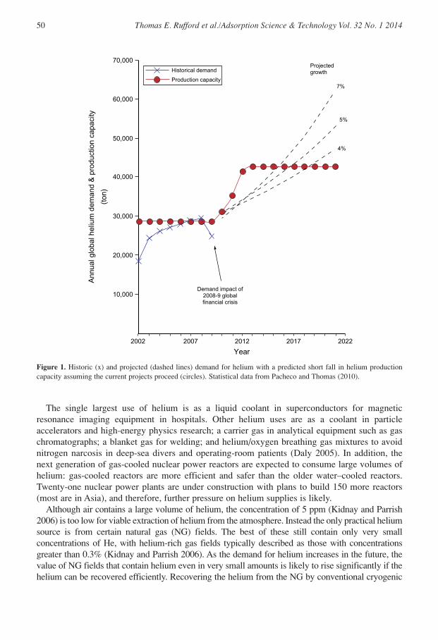
Helium is a unique gas with a wide range of important medical, scientific and industrialapplications based on its extremely low boiling temperature (4.2 K), inert and non-flammablenature, and small molecular size. The global demand for helium in 2010 was approximately30,000 t with a value close to USD$1 billion; (U.S. Geological Survey 2010) and, following arecovery from the economic downturn of 2008–2009, projections show a continued increase indemand for helium of 5–7% per annum (Pacheco and Thomas 2010). Much of this forecastdemand growth will be in Asia, especially in the developing economies of China and India. Newhelium production facilities have recently been commissioned in Algeria, Qatar and Australia:Darwin has the only helium extraction plant in the southern hemisphere (West 2009). However,as the projections in Figure 1 show, the production capacity of these plants and other plannedprojects currently fail to meet the projected demand for helium.
*Author to whom all correspondence should be addressed. E-mail: [email protected] (E. May).
The single largest use of helium is as a liquid coolant in superconductors for magneticresonance imaging equipment in hospitals. Other helium uses are as a coolant in particleaccelerators and high-energy physics research; a carrier gas in analytical equipment such as gaschromatographs; a blanket gas for welding; and helium/oxygen breathing gas mixtures to avoidnitrogen narcosis in deep-sea divers and operating-room patients (Daly 2005). In addition, thenext generation of gas-cooled nuclear power reactors are expected to consume large volumes ofhelium: gas-cooled reactors are more efficient and safer than the older water–cooled reactors.Twenty-one nuclear power plants are under construction with plans to build 150 more reactors(most are in Asia), and therefore, further pressure on helium supplies is likely.
Although air contains a large volume of helium, the concentration of 5 ppm (Kidnay and Parrish2006) is too low for viable extraction of helium from the atmosphere. Instead the only practical heliumsource is from certain natural gas (NG) fields. The best of these still contain only very smallconcentrations of He, with helium-rich gas fields typically described as those with concentrationsgreater than 0.3% (Kidnay and Parrish 2006). As the demand for helium increases in the future, thevalue of NG fields that contain helium even in very small amounts is likely to rise significantly if thehelium can be recovered efficiently. Recovering the helium from the NG by conventional cryogenic
50 Thomas E. Rufford et al./Adsorption Science & Technology Vol. 32 No. 1 2014
70,000
60,000
50,000
40,000
30,000
20,000
10,000
2002 2007 2012
Historical demand
Production capacity
2017 2022
Ann
ual g
loba
l hel
ium
dem
and
& p
rodu
ctio
n ca
paci
ty
Demand impact of2008-9 globalfinancial crisis
Projectedgrowth
Year
7%
5%
4%
(ton
)
Figure 1. Historic (x) and projected (dashed lines) demand for helium with a predicted short fall in helium productioncapacity assuming the current projects proceed (circles). Statistical data from Pacheco and Thomas (2010).
distillation methods is expensive and energy intensive. However, gas field developments based onliquefied NG (LNG) plants have a natural advantage in terms of helium recovery because themarginal extraction cost can be small relative to the potential additional revenue. New technologiesthat more efficiently extract and purify the helium could make that natural advantage even morelucrative and/or lower the concentration of helium needed in the gas to make extraction worthwhileeconomically. The global LNG industry is undergoing a rapid expansion in capacity to meet thegrowing demand for NG; the International Energy Agency predicts that by 2020 the total annualliquefaction capacity will increase from an estimated 370 billion cubic meters in mid-2011 to nearly870 billion cubic meters by 2020 (International Energy Agency 2011). Several of the proposed LNGprojects may present opportunities to recover helium as a saleable product in the liquefaction process.
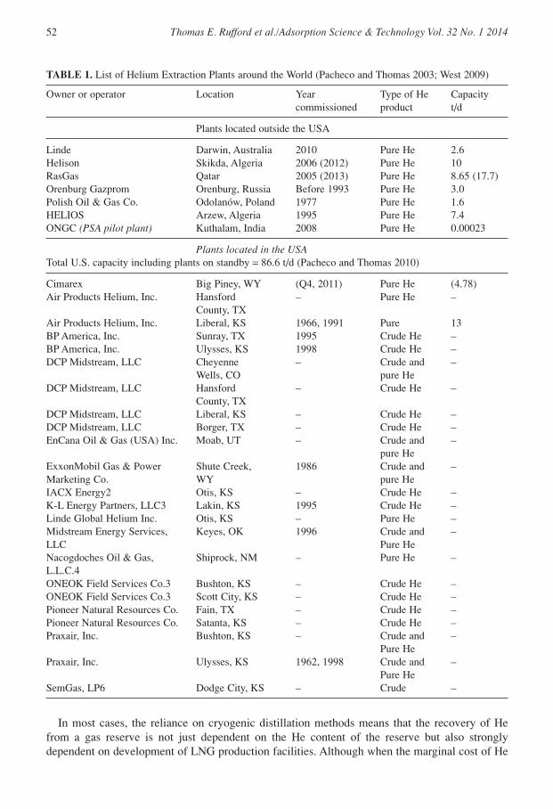
Helium extraction facilities currently in operation are listed in Table 1. There were 22 heliumplants operating in the continental USA in 2009, of which all but two used a cryogenic separationtechnology (Pacheco and Thomas 2010). The helium plants in the USA accounted for 71% ofglobal helium production in 2009 with the remainder produced in Algeria, Qatar, Poland andRussia. The first helium production plant in the southern hemisphere was commissioned inDarwin in March 2010 (liquid He product 860 l/hour = 2.6 t/d; Lindemann et al. 2010).
Besides the Darwin LNG plant, other recently constructed helium production plants are thosedesigned by Air Liquide in Ras Laffan Qatar (2005, 660 MMscf/year = 8.65 t/d; Daly 2005), andanother by Linde Engineering in Skikda Algeria (start-up 2006, 10 t/d; Linde-Engineering 2010).Air Liquide and RasGas announced in May 2010 plans to build a second helium extraction unit atRas Laffan (Air Liquide 2010). Other significant He extraction plants under development includean expansion of the Skikda plant in 2012 (Chemical Week 2007) and the construction of a new 1MMscfd (4.78 t/d) He plant in Wyoming, USA (Air Products & Chemicals 2010). Conventionalcryogenic distillation processes are used for He recovery in each of these new projects.
The largest scale He recovery plants recently constructed or in development all use cryogenicdistillation to perform the bulk of gas separations. Adsorption processes are used in the Hepurification stages to adsorb trace amounts of N2 (and Ar) from the upgraded He (>90% He), butat present there is no alternative commercially available process technology that is competitivewith cryogenic distillation for the He recovery from low concentration He streams at the gas flowrates characteristic of large LNG developments. In other industrial applications, such as theproduction of hydrogen in the chemical and petrochemical industries (Ritter and Ebner 2007), thepotential has been demonstrated for adsorption and membrane separation processes to achievelarge capital and energy-cost savings compared with cryogenic distillation processes. One pilot-plant scale pressure-swing adsorption (PSA) process for He recovery from a 0.04-MMscfd NGfeed containing 6% He is reported by Das et al. (2008). Several adsorption-based processes forHe recovery disclosed in patents are described later in this review. Helium extraction plants usingmembrane separation have reportedly been used since 1985 (Häussinger et al. 2005) and weprovide here a summary of the available literature on membrane units for He recovery.
This paper reviews the conventional cryogenic processes for helium recovery, including therecently constructed helium plants in Qatar and Australia, and then examines the potential ofemerging technologies for more efficient helium production processes. Conventional heliumplants generally use cryogenic distillation to produce crude helium and then use PSA to purify itto the level required for liquefaction and sales. The conventional PSA processes used in heliumpurification adsorb the non-helium components present in the feed gas. Scope exists to optimizethese standard PSA processes by operating at lower temperatures, using improved adsorbents, andwith rapid PSA cycles. Emerging technologies for helium upgrade and purification are eitherbased on adsorption or membrane separations.
A Review of Conventional and Emerging Process Technologies for the Helium Recovery 51
In most cases, the reliance on cryogenic distillation methods means that the recovery of Hefrom a gas reserve is not just dependent on the He content of the reserve but also stronglydependent on development of LNG production facilities. Although when the marginal cost of He
52 Thomas E. Rufford et al./Adsorption Science & Technology Vol. 32 No. 1 2014
TABLE 1. List of Helium Extraction Plants around the World (Pacheco and Thomas 2003; West 2009)
Owner or operator Location Year Type of He Capacitycommissioned product t/d
Plants located outside the USA
Linde Darwin, Australia 2010 Pure He 2.6Helison Skikda, Algeria 2006 (2012) Pure He 10RasGas Qatar 2005 (2013) Pure He 8.65 (17.7)Orenburg Gazprom Orenburg, Russia Before 1993 Pure He 3.0Polish Oil & Gas Co. Odolanów, Poland 1977 Pure He 1.6HELIOS Arzew, Algeria 1995 Pure He 7.4ONGC (PSA pilot plant) Kuthalam, India 2008 Pure He 0.00023
Plants located in the USATotal U.S. capacity including plants on standby = 86.6 t/d (Pacheco and Thomas 2010)
Cimarex Big Piney, WY (Q4, 2011) Pure He (4.78)Air Products Helium, Inc. Hansford – Pure He –
County, TXAir Products Helium, Inc. Liberal, KS 1966, 1991 Pure 13BP America, Inc. Sunray, TX 1995 Crude He –BP America, Inc. Ulysses, KS 1998 Crude He –DCP Midstream, LLC Cheyenne – Crude and –
Wells, CO pure HeDCP Midstream, LLC Hansford – Crude He –
County, TXDCP Midstream, LLC Liberal, KS – Crude He –DCP Midstream, LLC Borger, TX – Crude He –EnCana Oil & Gas (USA) Inc. Moab, UT – Crude and –
pure HeExxonMobil Gas & Power Shute Creek, 1986 Crude and –Marketing Co. WY pure HeIACX Energy2 Otis, KS – Crude He –K-L Energy Partners, LLC3 Lakin, KS 1995 Crude He –Linde Global Helium Inc. Otis, KS – Pure He –Midstream Energy Services, Keyes, OK 1996 Crude and –LLC Pure HeNacogdoches Oil & Gas, Shiprock, NM – Pure He –L.L.C.4ONEOK Field Services Co.3 Bushton, KS – Crude He –ONEOK Field Services Co.3 Scott City, KS – Crude He –Pioneer Natural Resources Co. Fain, TX – Crude He –Pioneer Natural Resources Co. Satanta, KS – Crude He –Praxair, Inc. Bushton, KS – Crude and –
Pure HePraxair, Inc. Ulysses, KS 1962, 1998 Crude and –
Pure HeSemGas, LP6 Dodge City, KS – Crude –
extraction may be relatively small compared with the total LNG plant costs, the additional capitalcost of cryogenic He extraction and purification plants means that a significant investmentdecision to install them is still required. New technologies that more efficiently extract and purifyhelium could lower the concentration of helium needed in the gas to make extraction worthwhileeconomically. Furthermore, the opportunities for alternative non-cryogenic He extractionprocesses may be increased in specific cases such as the development of remote, stranded orunconventional gas reserves including depleted gas fields like Hugoton, USA which may containpredominantly nitrogen (Kammerzell 2011; Clarke et al. 2013). Similarly, novel or unusual fielddevelopment scenarios, such as floating LNG production or reserves for which non-cryogenictechnologies, such as PSA, need to be considered for N2 rejection (Mitariten 2009) also presentmultiple opportunities for the application of emerging helium recovery technologies.
2. CONVENTIONAL HELIUM RECOVERY AND UPGRADE TECHNOLOGY
2.1. Overview of Helium Extraction from NG
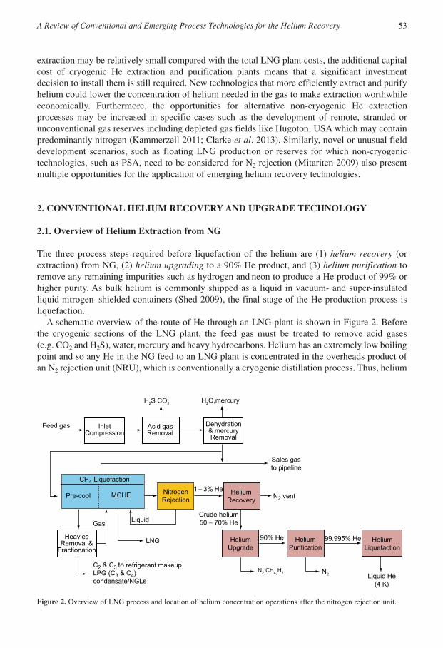
The three process steps required before liquefaction of the helium are (1) helium recovery (orextraction) from NG, (2) helium upgrading to a 90% He product, and (3) helium purification toremove any remaining impurities such as hydrogen and neon to produce a He product of 99% orhigher purity. As bulk helium is commonly shipped as a liquid in vacuum- and super-insulatedliquid nitrogen–shielded containers (Shed 2009), the final stage of the He production process isliquefaction.
A schematic overview of the route of He through an LNG plant is shown in Figure 2. Beforethe cryogenic sections of the LNG plant, the feed gas must be treated to remove acid gases (e.g. CO2 and H2S), water, mercury and heavy hydrocarbons. Helium has an extremely low boilingpoint and so any He in the NG feed to an LNG plant is concentrated in the overheads product ofan N2 rejection unit (NRU), which is conventionally a cryogenic distillation process. Thus, helium
A Review of Conventional and Emerging Process Technologies for the Helium Recovery 53
InletCompression
1 − 3% He
Crude helium50 − 70% He
90% He
LiquidGas
Pre-cool MCHE
CH4 Liquefaction
LNG 99.995% He
Liquid He(4 K)
Feed gas
N2
Acid gasRemoval
Dehydration& mercuryRemoval
Sales gasto pipeline
HeliumRecovery
NitrogenRejection
HeaviesRemoval &
Fractionation
HeliumUpgrade
HeliumPurification
HeliumLiquefaction
C2 & C3 to refrigerant makeupLPG (C3 & C4)condensate/NGLs
H2S CO2 H2O,mercury
N2 vent
N2,CH4,H2
Figure 2. Overview of LNG process and location of helium concentration operations after the nitrogen rejection unit.
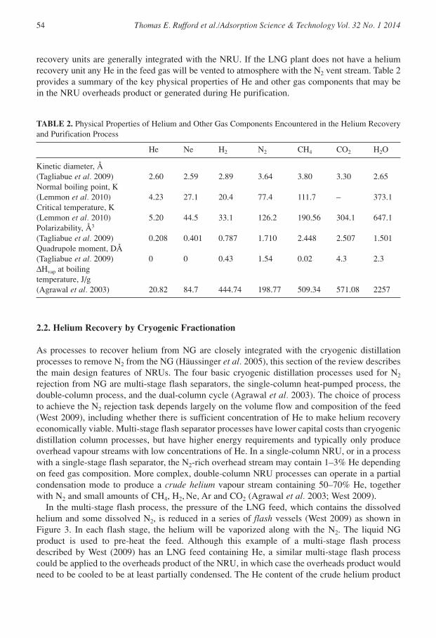
recovery units are generally integrated with the NRU. If the LNG plant does not have a heliumrecovery unit any He in the feed gas will be vented to atmosphere with the N2 vent stream. Table 2provides a summary of the key physical properties of He and other gas components that may bein the NRU overheads product or generated during He purification.
54 Thomas E. Rufford et al./Adsorption Science & Technology Vol. 32 No. 1 2014
TABLE 2. Physical Properties of Helium and Other Gas Components Encountered in the Helium Recoveryand Purification Process
He Ne H2 N2 CH4 CO2 H2O
Kinetic diameter, Å(Tagliabue et al. 2009) 2.60 2.59 2.89 3.64 3.80 3.30 2.65Normal boiling point, K(Lemmon et al. 2010) 4.23 27.1 20.4 77.4 111.7 – 373.1Critical temperature, K(Lemmon et al. 2010) 5.20 44.5 33.1 126.2 190.56 304.1 647.1Polarizability, Å3
(Tagliabue et al. 2009) 0.208 0.401 0.787 1.710 2.448 2.507 1.501Quadrupole moment, DÅ(Tagliabue et al. 2009) 0 0 0.43 1.54 0.02 4.3 2.3∆Hvap at boilingtemperature, J/g(Agrawal et al. 2003) 20.82 84.7 444.74 198.77 509.34 571.08 2257
2.2. Helium Recovery by Cryogenic Fractionation
As processes to recover helium from NG are closely integrated with the cryogenic distillationprocesses to remove N2 from the NG (Häussinger et al. 2005), this section of the review describesthe main design features of NRUs. The four basic cryogenic distillation processes used for N2
rejection from NG are multi-stage flash separators, the single-column heat-pumped process, thedouble-column process, and the dual-column cycle (Agrawal et al. 2003). The choice of processto achieve the N2 rejection task depends largely on the volume flow and composition of the feed(West 2009), including whether there is sufficient concentration of He to make helium recoveryeconomically viable. Multi-stage flash separator processes have lower capital costs than cryogenicdistillation column processes, but have higher energy requirements and typically only produceoverhead vapour streams with low concentrations of He. In a single-column NRU, or in a processwith a single-stage flash separator, the N2-rich overhead stream may contain 1–3% He dependingon feed gas composition. More complex, double-column NRU processes can operate in a partialcondensation mode to produce a crude helium vapour stream containing 50–70% He, togetherwith N2 and small amounts of CH4, H2, Ne, Ar and CO2 (Agrawal et al. 2003; West 2009).
In the multi-stage flash process, the pressure of the LNG feed, which contains the dissolvedhelium and some dissolved N2, is reduced in a series of flash vessels (West 2009) as shown inFigure 3. In each flash stage, the helium will be vaporized along with the N2. The liquid NGproduct is used to pre-heat the feed. Although this example of a multi-stage flash processdescribed by West (2009) has an LNG feed containing He, a similar multi-stage flash processcould be applied to the overheads product of the NRU, in which case the overheads product wouldneed to be cooled to be at least partially condensed. The He content of the crude helium product

will depend on the feed’s He concentration, as well as the available pressure drop and resultingtemperature change.
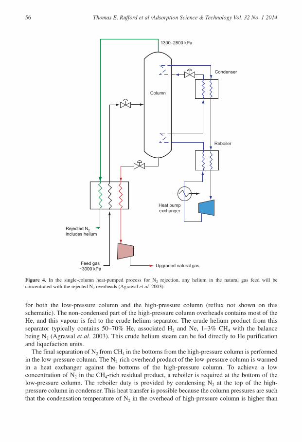
In the single-column heat-pumped process (Figure 4), a purified NG feed is pre-cooled in themain cryogenic heat exchanger (MCHE; against the rejected N2) and then fed to a high-pressurecolumn (1.3–2.8 MPa). The vapour rejected from the top of the column contains N2 and He.Methane is condensed and drawn from the bottom of the column. A closed-loop heat pump (thatuses methane as the working fluid) supplies both the reboiler heating and the condenser coolingduties to the column. The methane bottoms stream is flashed across a control valve to a lowpressure and warmed with the feed gas and the rejected N2 in the MCHE. The single-columnprocess produces only one N2-rich vapour stream with a He concentration of typically 1–3%depending on the He content of the feed gas.
A simplified process flow scheme of a modern, double-column process for N2 rejection andHe recovery from NG is shown in Figure 5 (this process is described by Häussinger et al. 2005).The feed gas is cooled against cold product streams in a cryogenic heat exchanger (MainFeed/product HX) and is fed to the bottom of the high-pressure column. In this high-pressurecolumn, the helium is recovered from the feed at typical operating pressures within the range of1–2.5 MPa (Agrawal et al. 2003). The high-pressure column’s partial condenser provides reflux
A Review of Conventional and Emerging Process Technologies for the Helium Recovery 55
Crudehelium
V-2
V-3
V-1
Residuenatural gas
Naturalgas feed
Figure 3. Schematic of a multi-stage flash process for the recovery of helium from natural gas.
for both the low-pressure column and the high-pressure column (reflux not shown on thisschematic). The non-condensed part of the high-pressure column overheads contains most of theHe, and this vapour is fed to the crude helium separator. The crude helium product from thisseparator typically contains 50–70% He, associated H2 and Ne, 1–3% CH4 with the balancebeing N2 (Agrawal et al. 2003). This crude helium steam can be fed directly to He purificationand liquefaction units.
The final separation of N2 from CH4 in the bottoms from the high-pressure column is performedin the low-pressure column. The N2-rich overhead product of the low-pressure column is warmedin a heat exchanger against the bottoms of the high-pressure column. To achieve a lowconcentration of N2 in the CH4-rich residual product, a reboiler is required at the bottom of thelow-pressure column. The reboiler duty is provided by condensing N2 at the top of the high-pressure column in condenser. This heat transfer is possible because the column pressures are suchthat the condensation temperature of N2 in the overhead of high-pressure column is higher than
56 Thomas E. Rufford et al./Adsorption Science & Technology Vol. 32 No. 1 2014
Condenser
Reboiler
Column
1300−2800 kPa
Heat pumpexchanger
Rejected N2includes helium
Upgraded natural gasFeed gas~3000 kPa
Figure 4. In the single-column heat-pumped process for N2 rejection, any helium in the natural gas feed will beconcentrated with the rejected N2 overheads (Agrawal et al. 2003).
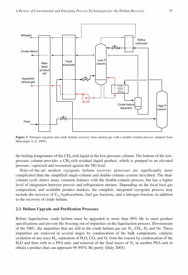
the boiling temperature of the CH4-rich liquid in the low-pressure column. The bottom of the low-pressure column provides a CH4-rich residual liquid product, which is pumped to an elevatedpressure, vaporized and rewarmed against the NG feed.
State-of-the-art modern cryogenic helium recovery processes are significantly morecomplicated than the simplified single-column and double-column systems described. The dual-column cycle shares many common features with the double-column process, but has a higherlevel of integration between process and refrigeration streams. Depending on the local feed gascomposition, and available product markets, the complete, integrated cryogenic process mayinclude the recovery of C2+ hydrocarbons, fuel gas fractions, and a nitrogen fraction, in additionto the recovery of crude helium.
2.3. Helium Upgrade and Purification Processes
Before liquefaction, crude helium must be upgraded to more than 90% He to meet productspecifications and prevent the freezing out of impurities in the liquefaction process. Downstreamof the NRU, the impurities that are still in the crude helium gas are N2, CH4, H2 and Ne. Theseimpurities are removed in several stages by condensation of the bulk components, catalyticoxidation of any trace H2, separation of H2O, CO2 and O2 from the reactor by condensation of theH2O and then with in a PSA unit, and removal of the final traces of N2 in another PSA unit toobtain a product that can approach 99.995% He purity (Daly 2005).
A Review of Conventional and Emerging Process Technologies for the Helium Recovery 57
Low Pcolumn
Refluxsubcooler
High Pcolumn
Crude heliumseparator
Low Preboiler/high P
condenser
FeedsubcoolerMain
feed/product
HX
Nitrogen
Crude helium
Feed
Upgradednatural gas
Figure 5. Nitrogen rejection and crude helium recovery from natural gas with a double-column process (adapted fromHäussinger et al. 2005).

Usually the bulk N2 is removed from the crude helium by further cryogenic distillation steps,at lower temperatures than the temperatures in the NRU. Crude helium, which may be combinedwith blowdown from the (downstream) PSA purifier, is cooled to around 80 K in a Perlite-filledcold-box heat exchanger, also known as the upgrader. Here it is partially condensed to provide anN2-rich liquid stream and a vapour stream of upgraded He containing approximately 90% He(Agrawal et al. 2003). The N2-rich liquid from the partial condensation is warmed and separatedto provide a waste stream that can be used to regenerate the (downstream) driers (Agrawal et al. 2003).
A typical process used to purify upgraded He is shown in Figure 6. The upgraded He is mixedwith air to provide combustion oxygen, pre-heated to above 300 K (Lindemann et al. 2010), andthen passed through a catalyst bed to oxidize any trace H2 or remaining hydrocarbons. The reactorproduct is cooled to condense any water produced by combustion of the H2. Molecular-sieveadsorption beds in a PSA unit may be used here for further dehydration, CO2 and O2 capture atthis stage.
58 Thomas E. Rufford et al./Adsorption Science & Technology Vol. 32 No. 1 2014
Crude helium26−70% he80 k120−200 kPa
Air
Preheater
3100 kPa
Chiller
Waterseparator
81 k
81 k99% he
93% he3000 kPa
To liquefaction99.999% he
68 k93% he3000 kPa
Purge gasrecycled to feedH2O
N2 N2
313 k
300 k H2 oxidationreactor
H2O/CO2 PSA Trace N2 PSA
Figure 6. Schematic of helium purification process (based on system reported by Agrawal et al. 2003 and Lindemannet al. 2010).
To achieve a He purity of 99.995% the dry, H2-free gas flows through additional cryogenic N2
condensation (Lindemann et al. 2010) and/or a low temperature PSA unit to remove N2 to lessthan 10 ppm (Agrawal et al. 2003). A typical PSA unit for this application is a four-bed unitcontaining a molecular sieve adsorbent such as zeolite 4A. Helium upgrade processes with PSApurification units using commercially available molecular sieves are available from Praxair,Linde, and Air Liquide. This PSA unit for trace N2 removal does not remove any Ne or unreactedH2 from the He stream. These light impurities must be removed after the gas has been cooled inthe liquefaction process using more adsorption to remove H2 at 80 K and then Ne at 20 K. TheN2-rich blowdown gas from the PSA purification unit is compressed, dried and recycled to theinlet of the upgrader where it is combined with the crude He feed.
Detailed discussions and comparisons of He liquefaction processes are beyond the scope of thecurrent review. Here we provide only a short description of common liquefaction processes; amore detailed review of He liquefaction processes is available in Häussinger et al. (2005). Mostindustrial processes for the liquefaction of helium are based around isenthalpic throttling of thepurified He across a Joule–Thomson valve. Purified helium is compressed (usually to 2 MPa) andpre-cooled to 80 K with either liquid N2 or exhaust from the helium expander, then cooled to
below 80 K with exhaust from the helium expander, or to approximately 20 K with a H2
refrigerant (Agrawal et al. 2003; Häussinger et al. 2005). The final cooling to liquefy the He isachieved by free expansion of the compressed gas.
2.4. Case Studies of Recent Helium Production Facilities
Conventional cryogenic-based helium recovery and purification systems are available fromvendors including Air Products, Praxair, Air Liquide and Linde. Here we present two case studieson recently commissioned He production facilities in Qatar and Australia.
2.4.1. Ras Laffan, Qatar
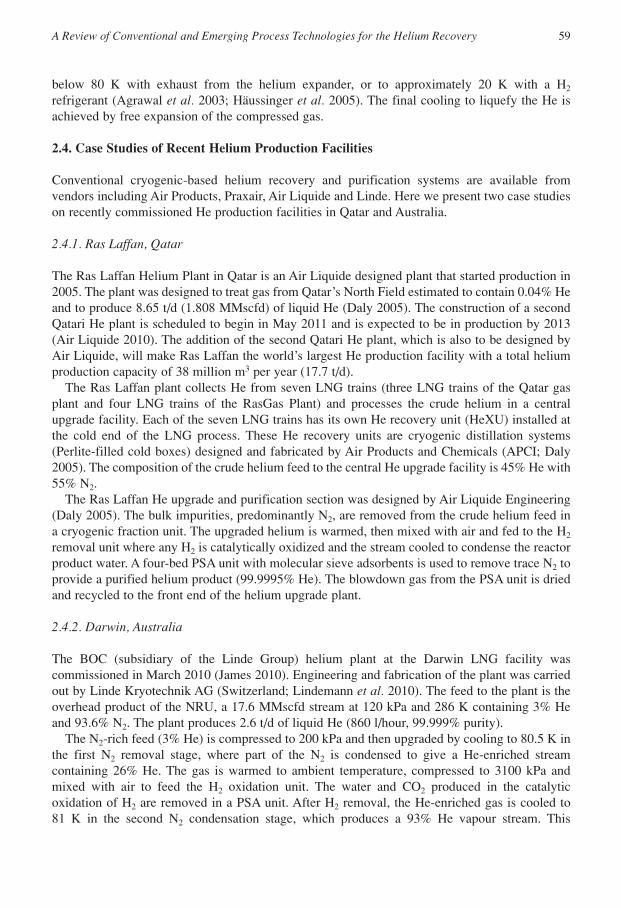
The Ras Laffan Helium Plant in Qatar is an Air Liquide designed plant that started production in2005. The plant was designed to treat gas from Qatar’s North Field estimated to contain 0.04% Heand to produce 8.65 t/d (1.808 MMscfd) of liquid He (Daly 2005). The construction of a secondQatari He plant is scheduled to begin in May 2011 and is expected to be in production by 2013(Air Liquide 2010). The addition of the second Qatari He plant, which is also to be designed byAir Liquide, will make Ras Laffan the world’s largest He production facility with a total heliumproduction capacity of 38 million m3 per year (17.7 t/d).
The Ras Laffan plant collects He from seven LNG trains (three LNG trains of the Qatar gasplant and four LNG trains of the RasGas Plant) and processes the crude helium in a centralupgrade facility. Each of the seven LNG trains has its own He recovery unit (HeXU) installed atthe cold end of the LNG process. These He recovery units are cryogenic distillation systems(Perlite-filled cold boxes) designed and fabricated by Air Products and Chemicals (APCI; Daly2005). The composition of the crude helium feed to the central He upgrade facility is 45% He with55% N2.
The Ras Laffan He upgrade and purification section was designed by Air Liquide Engineering(Daly 2005). The bulk impurities, predominantly N2, are removed from the crude helium feed ina cryogenic fraction unit. The upgraded helium is warmed, then mixed with air and fed to the H2
removal unit where any H2 is catalytically oxidized and the stream cooled to condense the reactorproduct water. A four-bed PSA unit with molecular sieve adsorbents is used to remove trace N2 toprovide a purified helium product (99.9995% He). The blowdown gas from the PSA unit is driedand recycled to the front end of the helium upgrade plant.
2.4.2. Darwin, Australia
The BOC (subsidiary of the Linde Group) helium plant at the Darwin LNG facility wascommissioned in March 2010 (James 2010). Engineering and fabrication of the plant was carriedout by Linde Kryotechnik AG (Switzerland; Lindemann et al. 2010). The feed to the plant is theoverhead product of the NRU, a 17.6 MMscfd stream at 120 kPa and 286 K containing 3% Heand 93.6% N2. The plant produces 2.6 t/d of liquid He (860 l/hour, 99.999% purity).
The N2-rich feed (3% He) is compressed to 200 kPa and then upgraded by cooling to 80.5 K inthe first N2 removal stage, where part of the N2 is condensed to give a He-enriched streamcontaining 26% He. The gas is warmed to ambient temperature, compressed to 3100 kPa andmixed with air to feed the H2 oxidation unit. The water and CO2 produced in the catalyticoxidation of H2 are removed in a PSA unit. After H2 removal, the He-enriched gas is cooled to81 K in the second N2 condensation stage, which produces a 93% He vapour stream. This
A Review of Conventional and Emerging Process Technologies for the Helium Recovery 59

upgraded helium vapour is cooled further to 68 K to condense more N2 and then flashed to providea product containing 99% He. The final purification is performed by a cryogenic PSA unit,removing the trace N2 not separated in the cryogenic flash units to less than 5 ppmv.
3. ADSORPTION-BASED PROCESSES FOR HELIUM RECOVERY
Adsorption-based separation processes are used to remove water, sulphur, mercury and carbondioxide from NG (Tagliabue et al. 2009), and as described earlier to remove trace impurities inHe purification. Gas separation using adsorption involves two primary steps, namely, adsorptionand desorption. During adsorption, one gas component is selectively adsorbed on a porous solidto produce a gas stream enriched in the less strongly adsorbed gas component. Once the poroussolid becomes, or approaches, saturation capacity the adsorbent must be regenerated. The gaseousproduct obtained during the desorption step is enriched in the strongly adsorbed component. Toachieve a continuous gas separation process by adsorption several technologies have beendeveloped. These technologies include temperature-swing adsorption (TSA), PSA, fluidizedadsorbent beds and moving adsorbent beds. Fluidized and moving bed operations are less widelyused in industrial gas separation than the cyclic-batch fixed bed operations of PSA and TSA(Seader and Henley 2006). In TSA processes, the external heat is supplied to increase the bedtemperature for desorption, but in PSA the regeneration is carried out at low temperature byreleasing pressure and purging the bed. Modern commercial PSA processes in operation rangefrom small devices for oxygen production from air for medical use (300 scfd, approximately 90%O2; Tagliabue et al. 2009) to large-scale processes for production of high-purity H2 from steammethane reformers (up to 200 MMscfd; Ritter and Ebner 2007).
The similarity in the molecular size of He (2.60 Å) and H2 (2.89 Å) and the fact that both havevery low boiling temperature means that PSA processes for helium purification potentially havemany common features with H2 purification processes. Sustained scientific and industrial interestin the purification of H2 over recent times suggests that there could be several new technologiesdeveloped for that application, which may be applicable to helium purification. For example, H2
purification PSA units have been built at large scales, including up to 200 MMscfd (Ritter and Ebner 2007; UOP 2010). Plants processing the largest gas flow rates for H2 purificationcan have up to 12 adsorber beds (such as UOP’s Polybed PSA; Sircar 2008). Commercial H2
purification plants operate by selective adsorption of other components including CH4, CO2, COand H2O. Similarly, helium purification PSA units operate by selective adsorption of the non-helium components. In general, modern PSA units for H2 purification use layered adsorbent bedswith three to four adsorbents (silica gel/alumina for H2O, activated carbon (AC) for CO2, and 5Azeolite for CH4, CO and N2; Ritter and Ebner 2007) and similar multi-layer bed designs aredescribed in patents for He recovery processes (Baksh 2010).
Pressure swing adsorption is used to remove trace N2 from upgraded He (>90 mol%) in the finalstages of industrial He purification processes to achieve 99.999% He product streams (Daly 2005; Lindemann et al. 2010). On a smaller scale, adsorption-based He purification andrecycle units are available for conserving He in scientific and medical applications. In each of thesecases, all the other components in the gas are adsorbed because He generally has the lowest affinityof any species for adsorption. For example, at ambient conditions (298 K, approximately 100 kPa),the He uptake on commercial zeolites 5A and 13X is less than 2 × 10⁻³ mmol/g (Malbrunot et al.1997) while the adsorption capacity for N2 on these materials is several hundred times greater(Cavenati et al. 2004; Saha et al. 2010), as shown in Table 3. Likewise, ACs have a very low
60 Thomas E. Rufford et al./Adsorption Science & Technology Vol. 32 No. 1 2014
capacity for He uptake at ambient conditions (1.15 × 10⁻³ to 2.27 × 10⁻³ mmol/g reported by Maggset al. (1960) for AC prepared from anthracite coal, nutshell or wood). At all scales, currentcommercial PSA units designed to treat He streams require that the feed stream is already upgraded(90%) because otherwise the adsorbent may be too readily saturated by non-helium components.
The upgrade and purification of helium from the NRU product (1–3% He) or crude helium (50–70% He) streams is predominantly a separation of N2 from He. Commercially available zeolitesand narrow pore–ACs with reasonable adsorption capacities for N2 make suitable adsorbents for Hepurification. A list of potential commercial adsorbents used in industrial processes for thepurification of H2 and/or described in patents for PSA helium recovery processes, which could beused in a PSA processes to separate heavier components from He is provided in Table 4.
A Review of Conventional and Emerging Process Technologies for the Helium Recovery 61
TABLE 3. Comparison of Adsorption Capacities of Zeolites 5A and 13X for He, N2 and CH4 at 298 K and100 kPa
Adsorbent He (mmol/g) N2 (mmol/g) CH4 (mmol/g)
Zeolite 5A 1.17 × 10⁻³ (Malbrunot 0.56 (Saha 0.84 (Sahaet al. 1997) et al. 2010) et al. 2010)
Zeolite 13X 1.31 × 10–3 (Malbrunot 0.28 (Cavenati 0.59 (Cavenatiet al. 1997) et al. 2004) et al. 2004)
TABLE 4. List of Commercial Adsorbents (Vendor Listed in Brackets) with Potential for SelectiveAdsorption of N2 and CH4 from Helium
Adsorbent type Trade names Species adsorbed
Zeolites ZSM-5 CH4, CO2, N2
HISIV 3000 (UOP)Zeolite 5A (UOP, Sigma)Zeolite 13X (UOP)
Wide pore–activated carbons BAX-1100 (Westvaco) CH4, CO2, N2
RB3, R2030, GAC 1240 (Norit)BPL 4 × 10 (Calgon)Acticarb EA1000 (ActivatedCarbon Technologies, Australiaand New Zealand)
Narrow-pore activated Maxsorb (Kansai Coke & N2 in finalcarbons Chemicals Co) purification stageCa- and Li-exchanged 13X N2 in final(Baksh 2010; Das purification stageet al. 2010)
In the following section, examples of PSA processes for helium recovery published in patentsand in the open literature are described. These include a commercial PSA helium extraction andpurification plant in India described in a 2008 report by Das et al., and processes claimed inpatents assigned to Nitrotec (D’Amico et al. 1996) and Praxair (Baksh 2010). All three examplesoperate by the adsorption of heavy components from the helium flow.

3.1. Survey of Pilot Plant and Patented PSA Processes for Helium Recovery
3.1.1. India’s Oil and Natural Gas Corporation PSA Plant
A pilot-scale PSA plant for the recovery and purification of He from a 0.04 MMscfd NG feedcontaining 0.06% He (88.5% CH4, 9.86% C2+, 1.18% N2 and 0.4% CO2) was trialled in TamilNadu by India’s Oil and Natural Gas Corporation (ONGC) in 2008 (Das et al. 2008). This pilotplant process had four process stages: (i) pre-treatment of the feed gas to remove C2+hydrocarbons and CO2, (ii) recovery of CH4, (iii) upgrade of He from N2 and (iv) He purification.Each process stage has three adsorber beds and operated at ambient temperature.
In Stage 1 the heavy components (CO2 and C2+) are selectively adsorbed at 450 kPa on a silicagel (196 kg/bed). In Stage 2, the CH4 is recovered by adsorption at 225 kPa onto an AC bed(38 kg/bed), allowing N2 and He to be concentrated to 16.1% and 1.4%, respectively, in the feedto Stage 3. In the regeneration of the Stage 2 beds, a CH4-rich gas is recovered and part of thisCH4-rich heavy product is recycled for use as a purge gas to regenerate Stage 1. The feed to Stage3 still contains a significant concentration of CH4 (82.5%) and in Stage 3 most of this CH4 isadsorbed along with N2 on zeolite 13X (3 kg/bed). The Stage 4 beds also contain 3 kg each ofzeolite 13X, which adsorbs the remaining CH4 and N2 at a pressure of 150 kPa, such that a 99%He product can be produced. Regeneration of each of the adsorption stages is performed byevacuating the beds to 6–7.5 kPa and by purging.
This pilot plant demonstrates the technical feasibility of using PSA processes to recover Hefrom NG streams. However, the ONGC process recovers only 65% of the He in the feed gas,which is much lower than the typical He recovery rate achieved in most conventional cryogenicdistillation processes (>95% recovery of He in feed gas). There are considerably opportunities toimprove the efficiency of PSA processes for He recovery through using improved cycle designs;optimized processing conditions by operation at, for example, cryogenic temperatures; andimprovements in adsorbent materials. One approach to improve adsorbent performance is todevelop adsorbents with higher capacities for N2 and, less critical here, CH4: for example Li-exchanged X-type zeolites with narrow pores around 9 Å wide (Das et al. 2010). A morechallenging approach is to develop a He-selective adsorbent; this would also have more impactbecause it would greatly reduce the size and energy requirements of resulting PSA beds and thecryogenic distillation towers. Currently, there are no commercial adsorbents available withsufficient He capacity and selectivity to realize such an industrial application. However, recentadvances in the development of adsorbents selective for H2 over N2, for example certain metal-organic frameworks (MOFs; Mallick et al. 2010), provide a new opportunity for developingHe-selective adsorbents because He and H2 have comparable molecular sizes and boiling points.Novel, helium-selective adsorbents are discussed further in the “Helium-Selective MicroporousAdsorbents” section.
3.1.2. Nitrotec Two-Stage PSA Process
A two-stage PSA process for the recovery of He from feed gases containing less than 10% He isdescribed in US patent no. 5542966 assigned to Nitrotec Corporation (D’Amico et al. 1996).Figure 7 shows a schematic of the example described in the patent. The example process treats2100 scfm (3 MMscfd) feed gas at a pressure of 50 psia containing 4% He, 26% hydrocarbons(CH4 and C2+) and 70% N2 to recover 80 scfm (0.55 t/d) of He product (99.999%). The first stageconsists of four adsorbent beds each filled with 11 m3 of AC, such as those with a specific surface
62 Thomas E. Rufford et al./Adsorption Science & Technology Vol. 32 No. 1 2014

area of 1150 m2/g and density of 0.45 g/cm3. The hydrocarbons and most of the N2 are adsorbedon the AC in this stage and the 90% He product gas flows to the second stage. The second stageconsists of four beds each filled with 1 m3 of AC. The light product from the second stage has apurity of 99.999% He and the waste gas from this stage (47 scfm, 75% He) is recycled as a purgegas in the first stage. This two-stage design and He-rich recycle stream is claimed to achieve Herecovery rates of 95%, which is approaching those of cryogenic distillation processes.
There are six cycle steps in the first PSA stage, namely, (i) adsorption, (ii) recycle, (iii)depressurization, (iv) evacuation to less than 10 kPa (absolute), (v) He pressurization with therecycle from the second stage, and (vi) recycle feed pressurization. The entire cycle duration istypically 480 seconds. There are five cycle steps in the second PSA stage, namely, (i) adsorption,(ii) depressurization, (iii) evacuation to less than 10 kPa (absolute), (iv) purge and (v) heliumproduct pressurization. The total cycle duration for Stage 2 is typically 360 seconds.
3.1.3. Praxair TSA and Vacuum PSA Process
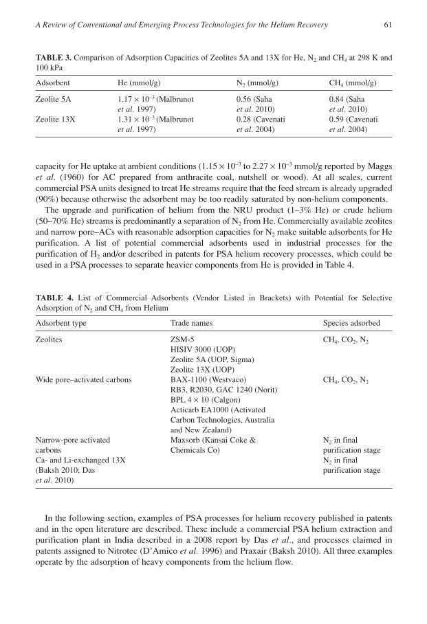
A patent assigned to Praxair (US patent no. 2010/0251892 A1) describes processes and systemsfor the recovery of He from feed gas containing less than 10% He using TSA and multiple vacuumPSA (VPSA) stages (Baksh 2010). A schematic of the system is shown in Figure 8. In eachadsorption stage the non-helium components are adsorbed from the gas. The VPSA stages operateat ambient temperature and at an adsorption pressure of 480 kPa. Baksh claims He recovery ratesof up to 95% using this process.
In this process design, the TSA stage protects the VPSA stage beds from rapid degradation andsaturation by removing CH4 and heavier components from feed. This guard bed strategy allowsmore efficient, smaller VPSA systems to be designed and reportedly achieves better He recoveryrates. The selection of adsorbents for the TSA stage is dependent on the composition of heavyhydrocarbons and other impurities such as H2S in the feed gas. If a TSA stage were required,
A Review of Conventional and Emerging Process Technologies for the Helium Recovery 63
Stage 2 PSAStage 1 PSA
90% He
Purge to stage 175% He
Helium product80 scfm,99.999%
Waste gasN2 + hydrocarbons
Feed2100 scfm, 4% He70% N2, 26% HC
Figure 7. Schematic of two-stage pressure-swing adsorption process for helium recovery described in US patent no.5542966 (D’Amico et al. 1996).
adsorbents in this stage may include aluminosilicates such as HISIV 3000 (UOP), zeolite ZSM-5supported on gamma alumina and AC such as BAX-1100 (Westvaco Corporation).
Baksh proposes four adsorber beds in each of the VPSA stages. Each bed in the VPSA stagesmay contain three layers of adsorbents including bed loading plans with a top layer of alumina, asecond layer of an adsorbent for removal of the heaviest components (e.g. CH4), and a bottomlayer of a high-capacity adsorbent such as zeolite CaX or LiX (Ca- and Li-exchanged 13X,respectively) chosen for optimum N2 adsorption. Commercial adsorbents suitable for the VPSAstages are AC s for the removal of CH4 and CO2, and zeolites such as 5A, Ca-X or Li-X to removeN2 and any O2 or argon contained in the feed gas.
4. MEMBRANE SEPARATION PROCESSES FOR HELIUM RECOVERY
Gas permeation through a homogeneous membrane is a solution-diffusion phenomenon and thepermeation coefficient Pi for a component gas is a product of the solubility coefficient Si and thediffusivity coefficient Di. The ability of a membrane to separate components of a gas mixture canbe described by the ratio of the permeation coefficients as shown in equation (1), where α is theselectivity or separation factor of gaseous components i and j (Häussinger et al. 2005)
(1)
As the He molecule is smaller in diameter than the other components of the NG, its diffusivitycoefficient in most homogeneous membranes will be greater than those of the other components.Thus, most homogeneous membranes exhibit a high permeability for He compared with N2, CH4,CO2 and other components of NG.
The extraction of helium from NG using membranes has been discussed for more than 40 years(Stern et al. 1965; Häussinger et al. 2005). Helium extraction plants using membrane separationhave reportedly been used since 1985 (Häussinger et al. 2005). At least one vendor (Ube
n αij
i
j
i i
j j
P
P
D S
D S= =
64 Thomas E. Rufford et al./Adsorption Science & Technology Vol. 32 No. 1 2014
Stage 2 VASAStage 1 VPSA
Buffertank
480 kPaBuffertank
Buffertank
Plow = 60.9 kPa
Plow = 60.9 kPa
Helium product>99.9% He
Stage 1 waste
Stage 2 VPSA tail gasrecycle to stage 1 VPSA
Regen gasfor TSA
Feed<10% He
TSA waste(to flare)
TSA
Figure 8. Schematic of a He recovery process using a temperature-swing adsorption unit upstream of two vacuumpressure-swing adsorption systems described by Baksh in a patent assigned to Praxair (Baksh 2010).
Industries) lists an example of a membrane process for He recovery from an N2-rich stream.Laverty and O’Hair (1990) report a membrane process for He recovery in Alberta, Canada.However, no data on the performance or operating experiences of these membrane-based Herecovery plants have been published in the open literature. By contrast, the use of H2-permeablemembranes in the production and purification of H2 has been described in the literature [e.g. Ritterand Ebner’s review of H2 purification technologies (2007)].
The first helium extraction membranes included tubular silicate and quartz glass membranesand, later, permeable polymeric membranes. Recently reported membranes suitable for Heseparation from N2 and CH4 include those constructed from ultra-microporous silica (Barboiu etal. 2006), molecular sieve carbons, porous graphene (Schrier 2010), titanium silicates (Li et al. 2011), polyimides and mixed matrix membranes of polyimides and zeolitic imidizolateframeworks (ZIFs; Bernado et al. 2009). Many of these membranes have been successfullyapplied in the separation of H2 from CO2, CH4, O2 and N2. Table 5 lists the selectivity for He overN2 and CH4 for several membranes. From the available literature on membrane materialsperformance, and in combination with reports of industrial H2-selective membranes, the mostpromising membranes for achieving a high selectivity for He over H2 appear to be ultra-microporous inorganic membranes and glassy polymeric membranes (polymers with glasstransition temperatures above the operating temperature). The aromatic polyimide membranelisted in Table 5 is an example of a glassy polymeric membrane.
A Review of Conventional and Emerging Process Technologies for the Helium Recovery 65
TABLE 5. Permeability Selectivity of Helium, Nitrogen and Methane in Inorganic and Organic MembraneMaterials (Häussinger et al. 2005)
Membrane material Temperature, °C Selectivity α
PHe/PN2 PHe/PCH4
Inorganic membranesPorous glass, Vycor type 25 2.5 1.8Molecular sieve carbon (3–5 Å) 25 20 –
Organic membrane materialsEthyl cellulose 20 11 2.8Polytetrafluoroethylene 20 31 42Polycarbonate 20 14.3 18.6Aromatic polyimide 35 74 165
4.1.1. Industrial and Patented Membrane Systems for Helium Recovery
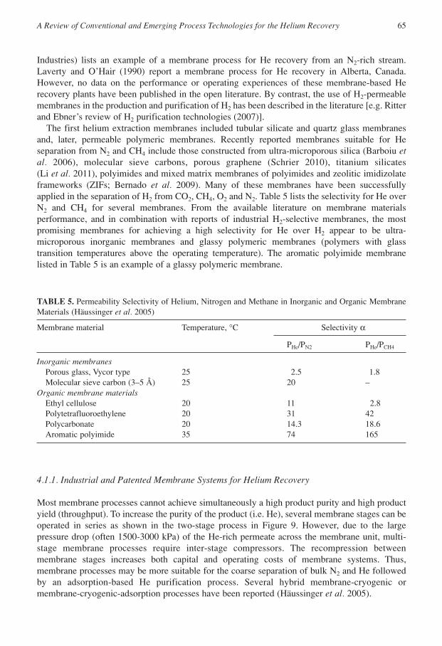
Most membrane processes cannot achieve simultaneously a high product purity and high productyield (throughput). To increase the purity of the product (i.e. He), several membrane stages can beoperated in series as shown in the two-stage process in Figure 9. However, due to the largepressure drop (often 1500-3000 kPa) of the He-rich permeate across the membrane unit, multi-stage membrane processes require inter-stage compressors. The recompression betweenmembrane stages increases both capital and operating costs of membrane systems. Thus,membrane processes may be more suitable for the coarse separation of bulk N2 and He followedby an adsorption-based He purification process. Several hybrid membrane-cryogenic ormembrane-cryogenic-adsorption processes have been reported (Häussinger et al. 2005).
In the example two-stage membrane system shown in Figure 9, each membrane separationstage consists of a row of separators with each containing a hollow fibre bundle (H_ussinger et al.2005). An aromatic polyimide polymer membrane with an effective area of 9000 m2/m3 of volumeis used in each membrane stage. This membrane material is suitable for operation at temperaturesfrom –80 to 150 °C and tolerates NG impurities such as water, H2S and C5+ hydrocarbons.Although this membrane process is reported to recover 95% of the He in the feed gas and reducesthe N2 concentration to less than half of the feed, the crude helium product still contains asignificant concentration of CH4. The membrane is also CO2 permeable. Clearly this exampleshows that with a membrane process alone it would be difficult to achieve the required productpurity of 99% He from an NG feed. The case of recovering He from the NRU overhead productshould be less intensive than from the NG feed gas, but the data in Table 5 show that the selectivityof the membrane process for He from N2 is still too low to achieve the desired separationperformance in two stages. Several membrane stages with inter-stage recompression would berequired to achieve a high-purity He product.
66 Thomas E. Rufford et al./Adsorption Science & Technology Vol. 32 No. 1 2014
Stage 1 permeateP = 105 kPa11.2% He22.3% N266.1% CH40.3% CO20.03% C2+
FeedP = 3500 kPa2.40% He24.54% N272.71% CH40.07% CO20.28% C2+
Crude heliumP = 105 kPa59.33% He10.02% N2
29.68% CH40.76% CO20.01% C2+
N2-rich recycle
CH4 + N2residue
Membranestage 1
Membrane stage 2
Figure 9. Process schematic of a two-stage membrane helium recovery system (Häussinger et al. 2005).

Membrane Technology and Research Inc. describe in US patent no. 2005/0217479 A1membrane systems for the recovery of He from reject streams in gas processing, which mayinclude vent streams, fuel gas streams and purge streams (Hale and Lokhandwala 2005). Thispatent claims that the process may use any type of membrane that can provide an adequate He fluxand a high selectivity for He over the other principle components of the reject gas (N2, CH4, CO2).Fluorinated, glassy polymer membranes are the preferred embodiment. This patent providesselectivity data for several commercial polymeric membrane materials including Hyflon AD60(Solvay Plastics) and Cytop (Asahi Glass).
Another Membrane Technology and Research Inc patent, US patent no. 6630011 B1, describesa process for the removal of N2 from NG using two or more membrane stages (Baker et al. 2003).An example including the concentration of He in the N2-rich product is also described in this patent.The process uses a CH4-selective membrane operating at –40 to 0 °C in the first stage followed byan N2-selective membrane in the second stage. This patent is not specific to separation of He froman N2-rich stream but does demonstrate the potential application of membranes at flow scales andoperating conditions (low temperature and high pressure) characteristic of an LNG facility.
Shoji and Moriya describe a He purification method based on hollow glass fibre membranes inUS patent no. 2003/0221448 A1 (Shoji and Moriya 2003). The glass fibre membrane walls havepores of 1.5 nm, which were created by the incorporation and the subsequent leaching of alkalimetal ions in the wall surfaces. The selective permeation rate of these hollow glass fibremembranes for He over N2 is claimed to be 1800–2000. An example system to recover He froma 120,000 Nm3/h feed gas containing 60% CH4, 1.5% He and the balance N2 is described in thispatent. The membrane module consisted of 16 basic membrane units of 20 cm diameter and 3.5m length each having a bundle of 70-µm diameter glass hollow fibres. The feed gas is supplied at1.27 MPa and the low-pressure He permeate is obtained at 120 kPa.
5. FUTURE RESEARCH AND DEVELOPMENT NEEDS
The literature survey identified that cryogenic distillation is the most commonly used processtechnology for He recovery from NG. Much of the helium recovery literature on process advancesin new plants describes the optimization of the cryogenic refrigeration processes. Although thebulk of the separation is performed by cryogenic distillation, adsorption processes are alreadyused in the helium upgrading and purification stages of conventional processes to remove anyremnant contaminant species, such as N2 and H2.
The literature survey identified that improvements in He recovery technologies may beachieved through developments or major breakthroughs in adsorption or membrane separationprocess. Helium recovery and purification processes are comparable in many ways with systemsdesigned for hydrogen purification. Thus, many of recent technological advances for H2
separation from CH4, N2 and CO2 may be applicable to a He recovery process, which could allowquicker deployment of the technology. Key areas identified that require further research anddevelopment are helium-selective adsorbents, helium-selective membrane processes, and flowsheet development of integrated cryogenic-membrane-adsorption systems.
5.1. Helium-Selective Microporous Adsorbents
Helium recovery by selective adsorption of the He from the N2 may allow process designs withsmaller adsorbent bed sizes. The small molecule size of He (kinetic diameter 2.60 Å; Tagliabue
A Review of Conventional and Emerging Process Technologies for the Helium Recovery 67

et al. 2009) can be taken advantage by size or kinetic exclusion of larger N2 (3.64 Å) and CH4 (3.8Å) molecules in narrow-pore adsorbents or permeable membranes. Kinetically selectiveadsorption processes have been successfully applied in air separation units, and for N2 rejectionfrom NG in the Molecular Gate PSA process (Molecular Gate Adsorption Technology 2010). Thekinetic or steric separation of He from N2 would require adsorbents with pore openings of 4 Å ornarrower. In addition, the pore volume and/or surface area accessible to He but not N2 would needto be sufficiently high to allow practical adsorber bed sizes. Potential adsorbents for use in a He-selective PSA process may include carbon molecular sieves, small-pore commercial/syntheticzeolites 3A and 4A (Zeochem Molecular Sieves 2010), small-pore natural zeolites such asNatrolite (Breck 1974), novel zeolites such as PTS-1 (Shin et al. 2010), ZIFs and novel MOFadsorbents such as Mg-MOFs (Mallick et al. 2010).
The entrapment of He in carbon molecular sieve fibres and Type A zeolites at low pressures andtemperatures from 77 K to room temperature has been reported by a research group (Finkelsteinet al. 2003; Saig et al. 2003, 2005). Although the absolute volume of He adsorbed at low pressureswas small, the materials did adsorb some He at low pressures, and reasonable He uptakes wereobserved at higher pressures. For example, at 2000 kPa and 77 K they reported an uptake of 0.9mmol/g He on 5A zeolite.
Small-pore MOFs such as Mg-MOFs have shown potential for the selective adsorption of H2
from gases with larger molecules such as N2 and CO2 (Li et al. 2009; Mallick et al. 2010). Thesimilarity in the molecular size of He and H2 (2.89 Å), and the fact that both have very low boilingtemperature, suggests that these small-pore adsorbents may also be selective for He. For example,Mallick et al. (2010) report a chiral hexagonal Mg-MOF-1 with pore apertures of 4 Å. Ingravimetric measurements with pure gases at 77 K and a pressure of 100 kPa this Mg-MOF-1exhibited higher uptakes of H2 (3.07 mmol/g) than CO2 or N2 (0.57 and 0.08 mmol/g,respectively).
A synthetic small-pore zeolite that selectively adsorbs He and H2 from argon and CO2 wasreported by Shin et al. (2010). This adsorbent known as PST-1 is a potassium gallosilicatenatrolite with a high Ga content (Si/Ga = 1.28). The uptake of He on PST-1 at 101.3 kPa was 0.02mmol/g at 303 K and 0.082 mmol/g at 77 K. The fast kinetics for He and H2 uptake reported byShin et al. (2010) suggest this material could have potential as an adsorbent for a PSA-based Hepurification process, or as a material to be incorporated into a membrane separation process.
These published results demonstrate that reasonable He uptakes can be obtained on somemicroporous adsorbents at certain conditions and suggest that the development of a He-selectivePSA process may be possible. Further experimental studies with materials such as PST-1, narrowpore zeolites and MOFs are required to confirm the potential of He-selective PSA processes.However, understanding the sorption kinetics and equilibria of He, N2, CH4 and their mixtures inmicroporous adsorbents at low temperatures and high pressures is essential to the design ofindustrial gas separation processes.
Crucial to assessing the He selectivity of any of the novel adsorbents is making accuratemeasurements of He uptake. Helium pycnometry is a standard method for determining voidvolumes and skeletal densities of porous materials (Rouquerol et al. 1994). Central to this standardmethod is that He adsorption is often erroneously assumed to be negligible (Malbrunot et al. 1997);this assumption is only the case at elevated temperatures. The challenge of such measurements maybe addressed first with careful adsorbent density measurements with a pycnometer at elevatedtemperatures and operation of a commercial volumetric adsorption apparatus in an absolute volumemode (manual mode). This approach allows independent calibration of the adsorption sample celland the adsorbent void volume (Maggs et al. 1960; Malbrunot et al. 1997).
68 Thomas E. Rufford et al./Adsorption Science & Technology Vol. 32 No. 1 2014
5.2. Advanced Helium-Selective Membranes
There already exists a large body of published data for pure gas permeability coefficients of N2, CH4,CO2, H2 and He in membranes, because a common technique for measuring membrane selectivityis relative He permeation. Many of these studies were motivated by separation of CH4/N2, CO2/N2
or H2/CO2 mixtures and only a few studies have specifically targeted the development of membranesto recover He from CH4 or N2. A detailed analysis of the available pure gas permeability data couldhelp to identify the best membranes for He recovery applications. However, for real gas mixtures,such as NG streams and the overhead vapours from the NRU, the separation performance of themembrane will be affected by the interactions between gas components as well as the interactionbetween the components and membrane material. The measurement of membrane performance withrepresentative gas mixtures of the industrial application, that is low-concentration N2- or CH4-richstreams, at a range of temperature and pressures is required to assess the true ability of membraneunits to recover or purify helium from NG.
There remain critical challenges in the fabrication of membranes with high selectivities forhelium. For example, the fabrication of inorganic membranes from materials such as MOFs andZIF-8 requires the membranes to be defect free—a defect such as a crack or gap between MOFparticles would significantly affect the membrane selectivity. However, the control of the initialseeding steps in MOF synthesis on a membrane support substrate (Dumée et al. 2013), forexample, is challenging and the development of new techniques for fabrication of membrane isrequired if the most promising He-selective membranes are to be translated from the laboratory toindustrial-scale processes.
5.3. Integrated Cryogenic Distillation Membrane and Adsorption Systems
Several hybrid membrane-cryogenic distillation or membrane-adsorption processes for therecovery of He from NG and/or the rejection of N2-rich streams from NG have been suggested inthe open and patent literature (Behling et al. 2001; Häussinger et al. 2005). These hybridprocesses are those described in patents assigned to Advanced Extraction Technologies (Mehra1993; AET-Technology 2010) and Nitrotec Corporation (Stoner et al. 1997). In their US Patent2003/0221448 A1 reporting the use of a glass fibre membrane, Shoji and Moriya (2003) also referto an unexamined Japanese patent no. JP-A-54-110193 that describes a method to obtain a high-purity 99.95% He product from a gas mixture of 70% He and 30% N2 by a combination ofcryogenic separation and gas separation membrane units based on cellulose acetate. According toShoji and Moriya in the method of JP-A-54-110193, five membrane separation units are requiredto achieve a He purity of 99.95%.
Mehra describes in US patent no. 5224350 (Mehra 1993), assigned to Advanced ExtractionTechnologies, a process for the recovery of He from an N2-rich NG stream using a CH4 absorbercolumn, a membrane separation unit and a PSA unit. The N2-rich feed gas containing more than0.1% He is contacted with a lean physical solvent to remove CH4 and heavier hydrocarbons (inthe so-called Mehra absorption process). The CH4-rich solvent bottom product is flashed twotimes to recover a CH4 product gas and regenerate the solvent. The N2-rich overheads product ofthe contactor is fed to a membrane unit, which provides a low-pressure crude helium stream (50%He) and rejects the N2. The crude helium can be compressed to 200-3000 psig for direct sale orfed to a PSA unit which produces an N2 waste stream and a purified 99.99% He product. Themembrane material is selected for maximum He permeability and examples of Li- and Na-exchanged perfluorosulphonic acid polymers are suggested. The patent does not prescribe any
A Review of Conventional and Emerging Process Technologies for the Helium Recovery 69

particular adsorbents for the PSA unit, but any adsorbent suitable for adsorption of N2 and CH4
could be selected (such as an AC, aluminosilicate, or silica gel).In US patent no. 5632803 assigned to Nitrotec Corporation, Stoner et al. (1997) describe a
hybrid process consisting of a membrane separation unit and two PSA units in series to producea He product stream of more than 98% purity from feed containing 1.6% He, 26% hydrocarbonsand 72.2% N2 (5250 scfm, inlet pressure of approximately 1000 psig). The membrane unitcontains polyimide hollow fibres that are permeably selective for He from N2, CO2, CH4 and otherhydrocarbons. The concentration of He is enriched in the membrane unit by two to ten times andthis low-pressure product (65–100 psia) flows to the first PSA stage. In each PSA stage, there maybe three to five adsorbent beds filled with an adsorbent such as AC, aluminosilicate or silica gel,which have little affinity for He. The first PSA stage can contain 11 m3 of AC to adsorb most ofthe hydrocarbons and N2 from the gas and provide a 90% He product. This He-rich gas flows tothe second PSA stage, which contains 1 m3 of AC and produces a He product of more than 98%purity. The waste gas from the first PSA stage is mixed with the residue of the membrane unit.The waste gas of the second PSA stage (47 scfm, 73% He) is recycled to the feed of the first PSAstage.
There remains scope for the development and optimization of various He recovery processlayouts featuring cryogenic distillation, membrane separation and PSA modules. The technicalfeasibility, energy requirements and process economics of these integrated system designs need tobe assessed. Such an integrated process design, for example, may comprise cryogenic distillationof the 1% He feed to a crude helium stream, then coarse separation of the crude helium stream bya membrane system, and then final He upgrading in a PSA unit. In addition, the performance ofmembrane and adsorbents at low-temperature conditions needs to be assessed for integratedsystems, which operate at cryogenic conditions.
STANDARD GAS VOLUMES AND CONVERSIONS FOR HELIUM PRODUCT RATES
In this paper the basis for standard cubic feet (scf) is 14.969 psi and 60 °F (101.325 kPa, 288.75 K).The condition for Nm3 is defined at 101.325 kPa and 298.15 K.
The equivalent gas volume and mass flow rates of 1 t/d liquid He product in other commonlyused units of measures are as follows:Mass flow 1 t/dLiquid volume 5.557 slpmMolar flow 249.837 kmol/dGas volume 254.678 Nm3/hourGas volume 0.209 MMscfdGas volume 2.231 million Nm3/yearGas volume 76.302 MMscf/year
ACKNOWLEDGEMENTS
The support of the Chevron Energy Technology Company through the Chevron–UWA UniversityPartnership Program, the Western Australian Energy Research Alliance (WA:ERA) and theAustralian Research Council (LP0776928) for UWA’s gas process engineering research programis acknowledged. The Australian Research Council funding (DE140100569) for Rufford at theUniversity of Queensland is also acknowledged.
70 Thomas E. Rufford et al./Adsorption Science & Technology Vol. 32 No. 1 2014

REFERENCES
AET-Technology [homepage on the Internet]. (2010) http://www.aet.com/tech.htm (Accessed: December 16,2010).
Agrawal, R., Herron, D.M., Rowles, H.C. and Kinard, G.E. (2003) “Cryogenic technology.” In: Kirk-OthmerEncyclopedia of Chemical Technology, Vol. 8, John Wiley & Sons, Hoboken, NJ, pp. 40–65.
Air Liquide. (2010) “Qatar: dual success in helium market.” <http://www.airliquide.com/file/otherelement/pj/successes_qatar_helium%20eng103005.pdf> (Accessed: December 16, 2010).
Air Products & Chemicals (2010) “Air Products and Matheson break ground for new Wyoming heliumplant.” <http://www.airproducts.com/company/news-center/2010/10/1012-air-products-matheson-break-ground-for-new-wyoming-helium-plant.aspx> (Accessed: January 28, 2011).
Baker, R.W., Lokhandwala, K.A., Wijmans, J.G. and Da Costa, A.R. (2003) Nitrogen removal from naturalgas using two types of membranes, US patent no. 6630011 B1.
Baksh, M.S.A. (2010) Methods and systems for helium recovery, US patent no. 2010/0251892 A1.Barboiu, C., Mourgues, A., Sala, B., Julbe, A., Sanchez, J., de Perthuis, S. and Hittner, D. (2006)
Desalination 200, 89.Behling, R.-D., Peinemann, K.-V. and da Silva, L.B. (2001) Process for the separation/recovery of gases, US
patent no. 6179900 B1.Bernado, P., Drioli, E. and Golemme, G. (2009) Ind. Eng. Chem. Res. 48, 4638.Breck, D.W. (1974) Zeolite Molecular Sieves, John Wiley & Sons, New York.Cavenati, S., Grande, C.A. and Rodrigues, A.E. (2004) J. Chem. Eng. Data 49, 1095.Chemical Week. (2007) “New construction projects: Algerian lng plant will double helium capacity.”
Chemical Week, 169, 18.Clarke, R., Nuttall, W. and Glowacki, B. (2013) “Endangered helium: bursting the myth.” In: The Chemical
Engineer, Institution of Chemical Engineers, Rugby, UK, pp. 32–36.Daly, J.W. (2005) “Helium recovery from LNG.” International Petroleum Technology Conference, American
Association of Petroleum Geologists (AAPG); the European Association of Geoscientists and Engineers(EAGE); the Society of Exploration Geophysicists (SEG); and the Society of Petroleum Engineers (SPE),Doha, Qatar, pp. 1–4.
D’Amico, J., Reinhold, H.E.I. and Knaebel, K.S. (1996) Helium recovery, US patent no. 5542966.Das, N.K., Chaudhuri, H., Bhandari, R.K., Ghose, D., Sen, P. and Sinha, B. (2008) Curr. Sci. 95, 1684.Das, N.K., Kumar, P., Mallik, C. and Bhandari, R.K. (2010) Adsorpt. Sci. Technol. 28, 281.Dumée, L., He, L., Hill, M., Zhu, B., Duke, M., Schätz, J., She, F., Wang, H., Gray, S., Hodgson, P. and Kong,
L. (2013) J. Mater. Chem. A 1, 9208.Finkelstein, Y., Saig, A., Danon, A. and Koresh, J.E. (2003) Langmuir 19, 218.Hale, P.W. and Lokhandwala, K.A. (2005) Helium recovery from gas streams, US patent no. 2005/0217479
A1.Häussinger, P., Glatthaar, R., Rhode, W., Kick, H., Benkmann, C., Weber, J., Wunschel, H.-J., Stenke, V.,
Leicht, E., Stenger, H. (2005) Noble gases. In: Ullmann’s Encyclopedia of Industrial Chemistry, G. Walter,editor, Wiley-VCH Weinheim, Baden-Wärttemberg, Germany.
International Energy Agency. (2011) World Energy Outlook 2011, Paris, France.James, M. (2010) “Up, up and away: helium plant opens in Darwin.” <http://www.abc.net.au/news/stories/
2010/03/03/2835141.htm> (Accessed: Jan 28 2011).Kammerzell, J. (2011) “Helium to move from byproduct to preimary drilling target.”
<www.rigzone.com/news/article.asp?a_id = 112735> (Accessed: January 14, 2014).Kidnay, A.J. and Parrish, W. (2006) Fundamentals of Natural Gas Processing, CRC Press, Boca Raton, FL.Laverty, B. and O’Hair, G. (1990) The applications of membrane technology in the natural gas industry. In:
J.A. Howell, editor. The Membrane Alternative: Energy Implications for Industry, Elsevier SciencePublishing, Essex, UK, p. 176.
Lemmon, E.W., Huber, M.L. and McLinden, M.O. (2010) REFPROP, 8.1beta, National Institute ofStandards and Technology, Gaithersburg, MD.
Li, J.-R., Kuppler, R.J. and Zhou, H.-C. (2009) Chem. Soc. Rev. 38, 1477.
A Review of Conventional and Emerging Process Technologies for the Helium Recovery 71

Li, X., Zhou, C., Lin, Z., Rocha, J., Lito, P.F., Santiago, A.S. and Silva, C.M. (2011) MicroporousMesoporous Mater. 137, 43.
Linde-Engineering [homepage on the Internet] (2010) “Helium recovery and liquefaction.” <http://www.lindeengineering.com/en/process_plants/natural_gas_treatment/helium_production/index.html> (Accessed:December 2, 2010).
Lindemann, U., Boeck, S., Blum, L. and Kurtcuoglu, K. (2010) AIP Conf. Proc., 1218, 271.Maggs, F.A., Schwabe, P.H. and Williams, J.H. (1960) Nature 186, 956.Malbrunot, P., Vidal, D., Vermesse, J., Chahine, R. and Bose, T.K. (1997) Langmuir, 13, 539.Mallick, A., Saha, S., Pachfule, P., Roy, S. and Banerjee, R. (2010) J. Mater. Chem. 20, 9073.Mehra, Y.R. (1993) Process for recovering helium from a gas stream, US patent no. 5224350.Mitariten, M. (2009) “Nitrogen removal from natural gas with the Molecular Gate(tm) adsorption process.”
88th Annual Convention of the Gas Processors Association 2009, Gas Processors Association, SanAntonio, TX, pp. 544–555.
Molecular Gate Adsorption Technology [homepage on the Internet] (2010) <http://www.moleculargate.com>(Accessed: November 18, 2010).
Pacheco, N. and Thomas, D. (2010) 2009 Minerals Yearbook–Helium (Advance Release), U.S. GeologicalSurvey, Reston, VA.
Ritter, J.A. and Ebner, A.D. (2007) Sep. Sci. Technol. 42, 1123.Rouquerol, J., Avnir, D., Fairbridge, C.W., Everett, D.H., Haynes, J.H., Pernicone, N., Ramsay, J.D.F., Sing,
K.S.W. and Unger, K.K. (1994) Pure Appl. Chem. 66, 1739.Saha, D., Bao, Z., Jia, F. and Deng, S. (2010) Environ. Sci. Technol. 44, 1820.Saig, A., Danon, A., Finkelstein, Y. and Koresh, J.E. (2003) J. Chem. Phys. 118, 4221.Saig, A., Finkelstein, Y., Danon, A. and Koresh, J.E. (2005) J. Phys. Chem. B 109, 11180.Schrier, J. (2010) J. Phys. Chem. Lett., 1, 2284.Seader, J.D. and Henley, E.J. (2006) Separation Process Principles, John Wiley & Sons, Hoboken, NJ.Shed, G. (2009) “Q2 2009. Helium conservation and recovery.” <http://www.specialtygasreport.com/features/
386> (Accessed: October 28, 2010).Shin, J., Camblor, M.A., Woo, H.C., Miller, S.R., Wright, P.A. and Hong, S.B. (2010) Angew. Chem. Int. Ed.
Engl. 48, 6647.Shoji, K. and Moriya, A. (2003) Method of producing high-purity helium, US patent no. 2003/0221448 A1.Sircar, S. (2008) “Gas separation and storage by activated carbons.” In: E.J. Bottani and J.M.D. Tascón,
editors, Adsorption by Carbons, Elsevier, Amsterdam, pp. 565–592.Stern, S.A., Sinclair, T.F., Hareis, P.J., Vahldieck, N.P. and Mohr, P.H. (1965) Ind. Eng. Chem. 57, 49.Stoner, G., Reinhold, H.E.I., D’Amico, J. and Knaebel, K.S. (1997) Enhanced helium recovery, US patent
no. 5632803.Tagliabue, M., Farrusseng, D., Valencia, S., Aguado, S., Ravon, U., Rizzo, C., Corma, A. and Mirodatos, C.
(2009) Chem. Eng. J. 155, 553.UOP [homepage on the Internet] “Hydrogen management with PSA and recovery equipment.”
<www.uop.com/refining/1100.html> (Accessed: November 11, 2010).U.S. Geological Survey. (2010) Helium Statistics, Reston, VA.West, J.E. (2009). “Helium extraction and production techniques.” <http://www.specialtygasreport.com/
features/q3-2009-helium-extraction-and-production-techniques> (Accessed: January 27, 2011).Zeochem Molecular Sieves [homepage on the Internet] (2010) <http://www.zeochem.com/>
(Accessed: November 12, 2010).
72 Thomas E. Rufford et al./Adsorption Science & Technology Vol. 32 No. 1 2014