A Residual Gas Analyzer for Dry Etching Process · A Residual Gas Analyzer for Dry Etching Process...
5
1 English Edition No.47 June 2017 Feature Article A Residual Gas Analyzer for Dry Etching Process Makoto MATSUHAMA Concerning the dry process of the semiconductor device manufacturing, the monitoring of etching chamber conditions (pressure, temperature, gas concentra- tion, ...) is crucial. This time, as a study of a new application, we examined the etching chamber management by using the residual gas analyzer. Generally using a residual gas analyzer in a dry etching apparatus which uses halogen-containing gas has been being avoided because of concerns such as sensors life. By confirming the residual gas component in the chamber before etching, it was possible to illuminate the cleaning process. Introduction The HORIBA Advanced Technology Center, established in 2015, integrated its semiconductor business-related clean rooms and combined the technologies of the HORIBA Group for promoting the internal production of key components as the core technology and the develop- ment of applications of their own. In this report, the study results of the evaluation conducted on a dry etcher using chlorine gas (Model: RIE-400iP, manufactured by Samco Inc.) among the various types of dry etcher we have by installing a residual gas analyzer from the QL-MS01 series manufactured by HORIBA STEC (hereinafter referred to as “RGA [Residual Gas Analyzer]”) are intro- duced as follows: The objective of this study In the dry process included in semiconductor device man- ufacturing processes, the management of the condition of etching chamber becomes an important element in con- trolling such processes. In the past, we recommended the use of differential evacuation and avoided installing an RGA directly into an etching chamber for the process using halogen gas because of the concern over sensor life- time. This time, we conducted the evaluation by directly installing an RGA in dry etcher using halogen gas with cooperation from an equipment manufacturer. By managing the condition of an etching chamber using an RGA quantitatively, we studied the reduction of equip- ment startup time after an overhaul, the saving of labor required to condition the etching chamber, and the improvement of the quality of etching process for the purpose of optimizing the equipment operation methods based on our empirical rules. The evaluation was conducted with the following proce- dures: First, the observation of residual gas components during vacuuming after the overhaul of the etching cham- ber (washing of parts in the etching chamber), next, the verification of the influence on the etching chamber con- ditioning process and the etched shape, and then, the veri- fication of the influence of residual moisture content in the etching chamber on the etched shape. Equipment used Figure 1 shows the RGA installed in the ICP dry etcher. The RGA was mounted directly to the port on the etching chamber side with no modification and was monitored directly. At the time of this installation, the temperature of the external wall of the etching chamber was regulated at 70°C, and the periphery of the sensor on the RGA was heated to 100°C using a heater to prevent gas from being absorbed into the periphery of the sensor. A manual gate valve was placed between the sensor and the etching chamber to isolate it from the atmosphere in the etching chamber during the process to protect the sensor. RGAs are utilized in plasma and aging treatments using a vacuum etching chamber, as well as management of the gas process at the functional thin membrane formation and working processes. [1] This device, which is 20 times smaller than others, has achieved the compact sensor size as small as 5 cm, which is the smallest level in the world, is equipped with the sensor that is calibration-free and can be replaced by users, and enables low-vacuum measure-
Transcript of A Residual Gas Analyzer for Dry Etching Process · A Residual Gas Analyzer for Dry Etching Process...
1 English Edition No.47 June 2017
Feature Article
A Residual Gas Analyzer for Dry Etching ProcessFeature Article
A Residual Gas Analyzer for Dry Etching Process
Makoto MATSUHAMAConcerning the dry process of the semiconductor device manufacturing, the
monitoring of etching chamber conditions (pressure, temperature, gas concentra-
tion, ...) is crucial. This time, as a study of a new application, we examined the
etching chamber management by using the residual gas analyzer.
Generally using a residual gas analyzer in a dry etching apparatus which uses
halogen-containing gas has been being avoided because of concerns such as
sensors life. By confirming the residual gas component in the chamber before
etching, it was possible to illuminate the cleaning process.
Introduction
The HORIBA Advanced Technology Center, established in 2015, integrated its semiconductor business-related clean rooms and combined the technologies of the HORIBA Group for promoting the internal production of key components as the core technology and the develop-ment of applications of their own. In this report, the study results of the evaluation conducted on a dry etcher using chlorine gas (Model: RIE-400iP, manufactured by Samco Inc.) among the various types of dry etcher we have by installing a residual gas analyzer from the QL-MS01 series manufactured by HORIBA STEC (hereinafter referred to as “RGA [Residual Gas Analyzer]”) are intro-duced as follows:
The objective of this study
In the dry process included in semiconductor device man-ufacturing processes, the management of the condition of etching chamber becomes an important element in con-trolling such processes. In the past, we recommended the use of differential evacuation and avoided installing an RGA directly into an etching chamber for the process using halogen gas because of the concern over sensor life-time. This time, we conducted the evaluation by directly installing an RGA in dry etcher using halogen gas with cooperation from an equipment manufacturer.
By managing the condition of an etching chamber using an RGA quantitatively, we studied the reduction of equip-ment startup time after an overhaul, the saving of labor required to condition the etching chamber, and the improvement of the quality of etching process for the
purpose of optimizing the equipment operation methods based on our empirical rules.
The evaluation was conducted with the following proce-dures: First, the observation of residual gas components during vacuuming after the overhaul of the etching cham-ber (washing of parts in the etching chamber), next, the verification of the influence on the etching chamber con-ditioning process and the etched shape, and then, the veri-fication of the influence of residual moisture content in the etching chamber on the etched shape.
Equipment used
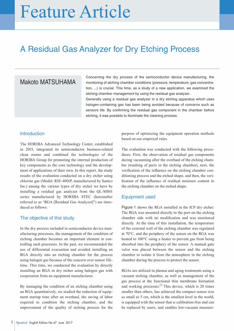
Figure 1 shows the RGA installed in the ICP dry etcher. The RGA was mounted directly to the port on the etching chamber side with no modification and was monitored directly. At the time of this installation, the temperature of the external wall of the etching chamber was regulated at 70°C, and the periphery of the sensor on the RGA was heated to 100°C using a heater to prevent gas from being absorbed into the periphery of the sensor. A manual gate valve was placed between the sensor and the etching chamber to isolate it from the atmosphere in the etching chamber during the process to protect the sensor.
RGAs are utilized in plasma and aging treatments using a vacuum etching chamber, as well as management of the gas process at the functional thin membrane formation and working processes.[1] This device, which is 20 times smaller than others, has achieved the compact sensor size as small as 5 cm, which is the smallest level in the world, is equipped with the sensor that is calibration-free and can be replaced by users, and enables low-vacuum measure-
Technical Reports
2English Edition No.47 June 2017
Feature Article
ment. This time, we used a sensor for halogen gases.
The dry etcher used in the evaluation was the load-lock type equipment for wafers up to 4 inches, intended for high-precision, high-uniformity processing of various semiconductors and insulating films for small-scale research and development. This equipment is equipped with an ICP source that can generate high-density plasma at low pressure and is intended for InP and III/V com-pound semiconductor devices that use Cl2, SiCl4, and Ar as process gas.
Dry etcher operating methods before conducting this study
Table 1 shows the flow of operation of the dry etcher before this study. Oxygen plasma cleaning of the etching chamber is performed before being opened to the atmo-sphere to minimize residual chloride components as a pretreatment before the overhaul of the etching chamber. After the etching chamber is opened to the atmosphere, the etching chamber is dismounted, washed with pure water, wiped with ethanol, dried, assembled, and then vacuumed.
Since the dry etcher used for this evaluation was a new equipment introduced immediately before the study, the equipment management had not yet been optimized. Therefore, the targeted degree of vacuum was set to a low value, giving first priority to prevent a failure from occur-ring during the etching process. Although the vacuum achievement level of up to approximately 5×10⁻⁴ Pa was recommended as the background level by the equipment manufacturer, we started the operation of this equipment based on the vacuum achievement level of 2×10⁻⁴ Pa as the initial control value due to fear of a process failure caused by residual moisture. Although vacuuming for 24-48 hours achieved the vacuum of 5×10⁻⁴ Pa, it required approximately 80 hours to reach the vacuum of 2×10⁻⁴ Pa.
Verification of the application effect of RGA
The results of the verification of the equipment mainte-nance and process management conditions are as follows:
The observation of the etching chamber condition during vacuuming was performed after the overhaul of the etch-ing chamber. The measurement was started at the vacuum of 0.1 Pa where the RGA is operable. Figure 2 shows the passage of 96 hours up to the vacuum of 2×10⁻⁴ Pa at
(a) (b)
RGA (Q-MASS)
Etching chamber
RGA
100°C@GASSENSOR
200°C@Electrostaticchuck
70°C@Chamberwall
Figure 1 (a) RGA set up (b) The heating temperature in the system
Table 1 Work procedure of the chamber overhaul and start-up
Phase Reactor OperationPeriod
(hr)Issue
1 Overhaul VACPre-treatment of the chamber pressure release(oxygen plasma cleaning)
2
2 Overhaul ATM Chamber overhaul (parts cleaning) 2 Expose Cl2
3 Overhaul ATMVacuum start ATM --> 2E-4 (Pa)
80 Long recovery time
4 Pre Etching Process VACPost-Maintenance of the chamber(O2 · Cl/Ar plasma cleaning)
4 Condition management
5 Etching Process VAC· Ref wafer· Product wafer
· Quality control· Process stability

3 English Edition No.47 June 2017
Feature Article
A Residual Gas Analyzer for Dry Etching Process
which the process can be started as well as the spectrums of residual gases at three vacuum start-up stages among which there is a difference in the degree of vacuum of approximately ten times. (The vertical axis shows the pressure and the horizontal axis shows the mass number.) It was confirmed that the degree of vacuum in the etching chamber reached 5×10⁻³ Pa in approximately 12 hours of vacuuming, but it took 80 hours until it reached 5×10⁻⁴ Pa.
When vacuuming was initiated, the peaks of moisture content, atmosphere, and component washing solution residue were confirmed. Since nitrogen and oxygen levels (blue dashed lines in Figure 2) remained unchanged since the initiation of vacuuming, they are considered to be the leakage level as the background of this equipment. Although HCl, which was eliminated during Work 1 Overhaul (Oxygen plasma cleaning treatment immedi-ately before opening to the atmosphere) shown in Table 1, was observed, it was considered to have reacted with residual chloride, and as a result the components and inner wall of the etching chamber were washed with water and were confirmed to have decreased as the vacu-uming process progressed like CO2 and ethanol absorbed into the inner wall of the etching chamber. In this way, checking the condition of the etching chamber during vacuuming using the RGA to see if the main component is atmosphere or water determines whether there is a leakage or not immediately after vacuuming, and the effect of preventing leakage problems is expected.
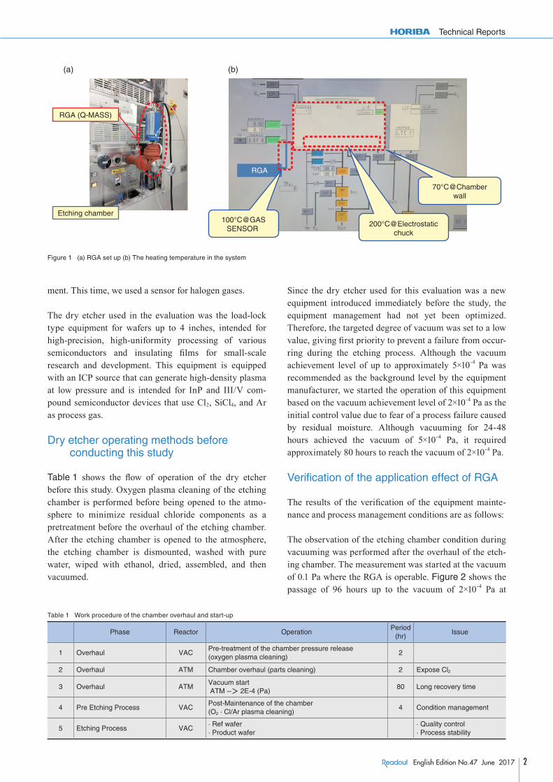
Next, the conditions of the etching chamber when the etching chamber conditioning treatment (oxygen-chlorine
plasma cleaning) were examined, and when it was not conditioned, and the results of etching performed in these conditions were compared (Figure 3).
During the conditioning after the overhaul of the etching chamber, organic matter and moisture are eliminated by oxygen plasma cleaning. Next, chlorine plasma cleaning is performed to eliminate residual oxygen. In chlorine plasma cleaning, it was originally assumed that chloride components needed to be supplied stably to the etching process by stabilizing the amount of etching gas absorbed into the inner wall of the etching chamber during the etching process as the inner wall of the etching chamber was coated with chloride components in advance. Although the lack of the cleaning was considered to have a bad influence on the roughness of the etched surface, etched shape, and rate and the selectivity of the mask material, a good etching shape was achieved on both sam-ples. From this result, it was confirmed that conditioning by plasma cleaning was not required under the etching conditions used for this study.
Next, in order to confirm the influence of the etching pro-cess and residual moisture, the results of residual moisture partial pressure and etching were compared between two different types of conditions between which there was a difference in the achieved degree of vacuum of ten times (Figure 4). Based on the above results, the etching pro-cess was performed both 2 hours after the initiation of vacuuming (at the vacuum of 1.2×10⁻³ Pa and moisture partial pressure of 4.5×10⁻⁴ Pa) and 84 hours after the ini-tiation of vacuuming (at the vacuum of 1.2×10⁻⁴ Pa and
Figure 2 Pump down monitoring
Technical Reports
4English Edition No.47 June 2017
moisture partial pressure of 5.2×10⁻⁵ Pa) with the etching chamber uncleaned after the overhaul. As a result, a good etching shape was observed on both samples. For all of these reasons, it was confirmed that the etching shape (flatness on crystal surface and taper shape) and the char-acteristics (selectivity of mask material) were not
influenced even if the process were performed at a lower degree of vacuum achieved (1×10⁻³ Pa) than had been originally estimated (2×10⁻⁴ Pa).
The reason why good etching results were obtained in this study is considered. Originally, there were concerns that
Figure 3 Chamber conditions before etching with/without dry cleaning sample
Figure 4 Chamber conditions before etching under Low/High degree vacuum state
Sample1. After dry-cleaning (Original) 2. Without dry-cleaning
Item Judgment criteria
Surface Mirror Surface Good (Mirror) Good (Mirror)
taper 80-90 degree Good (85 degree) Good (85 degree)
Selection ratio More-than 10 11 12
Sample1. Low-Vacuum 2. High-Vacuum
Item Judgment criteria
Surface Mirror Surface Good (Mirror) Good (Mirror)
taper 80-90 degree Good (85 degree) Good (85 degree)
Selection ratio More-than 10 16 12

5 English Edition No.47 June 2017
Feature Article
A Residual Gas Analyzer for Dry Etching Process
the micromask formed on the etched sample surface due to residual moisture had a negative infl uence on the pro-cess when etching an ln-based material using chlorine gas, such as a lawn-like rough surface and variation in verticality or etching rate due to a change in the side pro-tection condition.[2] The results obtained this time showed that such an event did not occur. This is considered to be because no moisture was left on the samples as the sample temperature during etching was as high as 200°C and SiCl4, as well as Ar used as etching gases, eliminated oxides on the surface.
From the above results, it was confi rmed that the original equipment management conditions shown in Table 1 were excessive as the process conditions used for this study, the action limit for the achieved degree of vacuum could be smaller by ten times, and the implementation of plasma cleaning for long hours using oxygen and chlorine was not required.
The above evaluation made it possible to reduce the time required until the etching chamber becomes usable by 98%, from 84 hours after overhaul to 2 hours after over-haul. For example, even if the etching chamber is opened to the atmosphere in the morning, it can be usable in the afternoon. Since it is also possible to shorten the time required for restoration in the event of a failure of the etching chamber, it became easier to check the condition inside the etching chamber when a failure occurred. In this way, it was confi rmed that quantitative equipment management using an RGA could improve the effi ciency of operation.
Conclusion
The effects of the quantifi cation of equipment manage-ment and the study of the etching mechanism were con-fi rmed through the application of an RGA to the dry etching process. It was also found that clarifying the con-dition of residual gas in the etching chamber enabled the detection of a failure early and prevented an etching pro-cess failure. Thus, through this evaluation, RGA was con-fi rmed to be effective in optimizing the conditions for managing chlorine-base dry etchers.
Acknowledgements
Finally, I would like to thank Mr. Hirohiko Nakano and Mr. Hirokazu Terai of the Production Engineering Department of Samco Inc. and Mr. Yohei Sakano of the Development Department of Samco Inc. for valuable dis-cussions and making useful suggestions on the etching process and management of dry etchers for this study.
References
[ 1 ] T.IKEDA, Readout, 28, 12 (2004)[ 2 ] T.TOKUYAMA, 半導体ドライエッチング技術 (Semiconductor Dry
Etching Technology), ISBN-13: 978-4782856284, 産業図書 (Sangyo-Tosho Co.) (1992)
Makoto MATSUHAMAAdvanced R&D CenterHORIBA, Ltd.
![Chapter 2thesis.library.caltech.edu/9054/13/lin_wei-hsun_2015_thesis_ch2.pdf · chemical etching. This etching process removes unmasked silicon, reveals the [111] crystal planes,](https://static.fdocuments.net/doc/165x107/5f085c7f7e708231d421a149/chapter-chemical-etching-this-etching-process-removes-unmasked-silicon-reveals.jpg)