A RESEARCH ON A RECONFIGURABLE HYPAR …library.iyte.edu.tr/tezler/master/mimarlik/T001189.pdf · A...
120
A RESEARCH ON A RECONFIGURABLE HYPAR STRUCTURE FOR ARCHITECTURAL APPLICATIONS A Thesis Submitted to the Graduate School of Engineering and Sciences of İzmir Institute of Technology in Partial Fulfillment of the Requirements for the Degree of MASTER OF SCIENCE in Architecture by Gözde SUSAM December 2013 İZMİR
-
Upload
phungtuong -
Category
Documents
-
view
214 -
download
0
Transcript of A RESEARCH ON A RECONFIGURABLE HYPAR …library.iyte.edu.tr/tezler/master/mimarlik/T001189.pdf · A...

A RESEARCH ON A RECONFIGURABLE HYPAR
STRUCTURE FOR ARCHITECTURAL
APPLICATIONS
A Thesis Submitted to
the Graduate School of Engineering and Sciences of
İzmir Institute of Technology
in Partial Fulfillment of the Requirements for the Degree of
MASTER OF SCIENCE
in Architecture
by
Gözde SUSAM
December 2013
İZMİR

We approve the thesis of Gözde SUSAM
Examining Committee Members:
Assoc. Prof. Dr. Koray KORKMAZ
Department of Architecture, Izmir Institute of Technology
Assist. Prof. Dr. Gökhan KİPER
Department of Mechanical Engineering, Izmir Institute of Technology
Assist. Prof. Dr. A. Vefa ORHON
Department of Architecture, Dokuz Eylül University
20 December 2013
Assoc. Prof. Dr. Koray KORKMAZ
Supervisor, Department of Architecture
Izmir Institute of Technology
Assoc. Prof. Dr. Şeniz ÇIKIŞ Prof. Dr. R. Tuğrul SENGER
Head of the Department of Architecture Dean of the Graduate School of
Engineering and Sciences

ACKNOWLEDGMENTS
I would like to express my special thanks to my supervisor Assoc. Prof. Dr.
Koray Korkmaz for his guidance and support throughout my research. Secondly, I
would like to thank other members of the examining committee; Assist. Prof. Dr.
Gökhan Kiper and Assist. Prof. Dr. A. Vefa Orhon, for their valuable suggestions and
comments.
I’m eternally grateful to my family for their morally and aptly contributions and
moreover being a part of my life.

iv
ABSTRACT
A RESEARCH ON A RECONFIGURABLE HYPAR STRUCTURE FOR
ARCHITECTURAL APPLICATIONS
Kinetic design strategy is a way to obtain remarkable applications in architecture.
These kinetic designs can offer more advantages compared to conventional ones. Basic
knowledge of different disciplines is necessary to generate kinetic designs. In other
words, interdisciplinary studies are critical. Therefore, architect’s knowledge must be
wide-ranging in order to increase novel design approaches and applications.
The resulting rich hybrid products increase the potential of the disciplines
individually. Research on kinetic structures shows that the majority of kinetic structures
are deployable. However, deployable structures can only be transformed from a closed
compact configuration to a predetermined expanded form.
The motivation of the present dissertation is generating a novel 2 DOF 8R
reconfigurable structure which can meet different hyperbolic paraboloid surfaces for
architectural applications. In order to obtain this novel structure; the integration between
the mechanism science and architecture is essential. The term reconfigurable will be
used in the present dissertation to describe deployable structures with various
configurations. The novel reconfigurable design utilizes the overconstrained Bennett
linkage and the production principals of ruled surfaces.
The dissertation begins with a brief summary of deployable structures to show their
shortcomings and their lack of form flexibility. Afterward, curved surfaces, basic terms
in mechanisms and overconstrained mechanisms were investigated. Finally, a proposed
novel mechanism which is inspired from the basic design principles of Bennett linkage
and the fundamentals of ruled surfaces are explained with the help of kinematic
diagrams and models.

v
ÖZET
MİMARİ UYGULAMALAR İÇİN HAREKETLİ HİPERBOLİK
PARABOLOİT STRÜKTÜRLER ÜZERİNE BİR ARAŞTIRMA
Mimarlar özgün tasarım yaklaşımlarını güçlendirebilmek adına diğer disiplinlerden
gelecek bilgilere, yeniliklere açık olmalı bu bilgileri kendi tasarımları ile
bütünleştirebilmelidirler. Bunun sonucunda ortaya çıkan hibrit ürünler, daha zengin
olup, disiplinlerin ayrı ayrı sahip oldukları potansiyelleri artırmaktadır. Kinetik tasarım,
mimaride özgün uygulamalar yaratmanın bir yoludur. Hareketli (kinetik) yapıların
günümüz durağan yapılarına göre birçok avantajı vardır. Günümüzde var olan birçok
durağan yapı değişen ihtiyaçlara cevap verememekte ve iklimsel değişikliklere adapte
olamamaktadır. Hareketli yapı veya yapı bileşenleri mimarlığın değişen ihtiyaçlara
adapte olabilme becerisini artırmaktadır. Bu tezin temel amacı; mimariyi bambaşka bir
bilim dalı olan mekanik bilimi ile harmanlayarak, günümüz mimarlığının ihtiyaçlarını
karşılayan hareketli, özgün bir yapı elemanı tasarlamaktır.
Dört çubuğun dört döner mafsalla bir araya getirilmesinden oluşan üç boyutlu
Bennett mekanizması ve çizel yüzeylerin üretim yönteminden yararlanılarak yeni bir
mekanizma geliştirilmiştir. Yeni mekanizmanın mafsal imalatı çok basit olup ve hareket
kabiliyeti sınırsızdır. Ayrıca, yeni mekanizma istenilen her tür hiperbolit paraboloit
biçimini alabilmektedir. Çalışmada; üretilen yeni mekanizmanın, mekanizmaya eklenen
ara çubuklara monte edilen kaplama malzemesi ile hareketli üst örtü olarak
kullanılabileceği öngörülmüştür. Tezde, konuşlanabilir yapılara, çizel yüzeylere, temel
mekanizma bilgisine ve Bennett mekanizmasının özelliklerine kapsamlı bir şekilde yer
verilmiştir. Bennett mekanizmasından esinlenerek oluşturulan yeni mekanizma ve bu
mekanizma ile oluşturulan mimari üst örtü, yapılan maketler ve kinematik
diyagramların yardımı ile anlatılmıştır.

vi
TABLE OF CONTENTS
LIST OF FIGURES................................................................................................................ viii
CHAPTER 1.INTRODUCTION1
1.1 Definition Of The Study ................................................................................... 1
1.2 Scope And Aim Of Dissertation ....................................................................... 2
1.3 Outline Of Dissertation .................................................................................... 2
CHAPTER 2. KINETIC DESIGN STRATEGY ............................................................. 3
2.1 Kinetic Design Strategy In Art And Architecture ............................................ 3
CHAPTER 3.DEPLOYABLE STRUCTURES ............................................................ 12
3.1 Review Of Previous Works ............................................................................ 12
3.2 Classification Of Deployable Structures ........................................................ 16
3.2.1 Gantes Classification ......................................................................... 16
3.2.1.1 Deployable Structures Based On Pantographs ...................... 18
3.2.1.2 Deployable Structures Based On 2-D Panels ........................ 27
3.2.1.3 Cable Membrane And Pneumatic Deployable Structures ..... 33
3.2.1.4 Tensegrity Deployable Structures ......................................... 41
3.2.1.5 Retractable Roofs .................................................................. 46
3.2.2 Pellegrino Classification .................................................................... 48
3.2.3 Hanaor Classification ......................................................................... 50
3.2.4 Korkmaz Classification ...................................................................... 53
3.3 Reconfigurable Structures .............................................................................. 57
CHAPTER 4. CURVED SURFACES........................................................................... 63
4.1 Single Curvature Surfaces .............................................................................. 64
4.2 Double Curvature Surfaces ............................................................................ 65
4.2.1 Synclastic Surfaces ............................................................................ 65
4.2.2 Anticlastic Surfaces ........................................................................... 68
4.2.2.1 Anticlastic Ruled surfaces ..................................................... 70
4.3 Freeform Curved Surfaces .............................................................................. 77
vii
CHAPTER 5. MECHANISMS ........................................................................................ 79
5.1 Overconstrained Linkages .............................................................................. 82
5.1.1 Geometric And Kinematic Principles Of Bennett Linkage ............... 84
5.1.2 Deficiencies And Alternative Works On Bennett Linkage ................ 86
5.2 Proposed 8R Reconfigurable Linkage Mechanisms ...................................... 90
CHAPTER 6. CONLUSION ......................................................................................... 100
6.1 Further Research ........................................................................................... 101
REFERENCES ............................................................................................................... 102

viii
LIST OF FIGURES
Figure Page
Figure 2.1.Basic pressure-response diagram showing relationship between the set of
pressures and the form ................................................................................. 4
Figure 2.2.Example of a kinetic painting ......................................................................... 6
Figure 2.3Kinetic object called “Molecule” ................................................................... 6
Figure 2.4.Project for a kinetic fountain .......................................................................... 6
Figure 2.5.Kinetic light object called “Flame” ................................................................ 7
Figure 2.6.Kinetic Sculpture called “Lighthouse” .......................................................... 7
Figure 2.7.Kinetic object inside Tallinn’s post office ..................................................... 8
Figure 2.8.Model photo and the model of self-building structure ................................... 9
Figure 2.9. Example of a drawbridge ............................................................................ 10
Figure 2.10. Pfalzkeller Emergency Service Center ...................................................... 11
Figure 2.11. Hemispheric in City of Arts and Science in Valencia .............................. 11
Figure 3.1. The doors of the temple ............................................................................... 12
Figure 3.2. Designs of deployable structures by Leonardo da Vinci ............................. 13
Figure 3.3. The Roman amphitheatres’ removable tension roof of canvas ................... 14
Figure 3.4. Iris dome by Hoberman ............................................................................... 15
Figure 3.5. Deployable Structure as an art piece ‘Bichos’ .......................................... 17
Figure 3.6. Gantes Classification of Deployable Structures .......................................... 18
Figure 3.7. The concept of a pantographs ...................................................................... 18
Figure 3.8. Pinero’s deployable structure ...................................................................... 19
Figure 3.9. Zeigler’s partial spherical dome .................................................................. 20
Figure 3.10. Escrig’s deployable vault by incorporating rigid plates. ........................... 20
Figure 3.11.Escrig’s Spherical Lamella Grids ............................................................... 21
Figure 3.12. a) Model of a Selffolding roof b) San Pablo Swimming Pool ................ 22
Figure 3.13. Expanding Hypar by Hoberman.California Science Center-
installation ................................................................................................... 23
Figure 3.14. Hoberman’s element, formed by identical angulated rods ........................ 24
Figure 3.15. Iris Dome (Hoberman 1991) 2000’s World Fair, Hannover ..................... 24
Figure 3.16. Hoberman’s Arch ...................................................................................... 25

ix
Figure 3.17. Deployable multi-angulated bar by You and Pellegrino ........................... 26
Figure 3.18. Deployable double curvature scissor hinge structures by Travis
Langbecker .................................................................................................. 26
Figure 3.19. Tom Van Mele’s visualization for retractable membrane roof ................. 27
Figure 3.20. Basic Layout of Foster’s module ............................................................... 28
Figure 3.21. Deployable Structures Based on 2-D Panels ............................................. 28
Figure 3.22.Triangulated foldable cylinders by Guest and Pellegrino .......................... 29
Figure 3.23. Half-shell with 3 Triangulated panels by “Kinetic Design Group” .......... 29
Figure 3.24. Perspective view of Tachi’s design ........................................................... 30
Figure 3.25. Tomohiro Tachi’s design to connect existing buildings ........................... 31
Figure 3.26. Bi stable foldable tubes ............................................................................. 32
Figure 3.27. Koman’s foldable polyhedron. .................................................................. 32
Figure 3.28. Displacement of beams and cable structures ............................................. 33
Figure 3.29. Traditional toldos providing shade in the streets of Cordoba,Spain ......... 34
Figure 3.30. Frei Otto’s sketches; umbrellas and blinds as possible additive,
convertible canopies. ................................................................................... 35
Figure 3.31. Frei Otto’s convertible roof design for Bad Hersfeld in 1968 .................. 36
Figure 3.32. Cable membrane roof for the open-air theatre in Wiltz by Bodo Rasch ... 37
Figure 3.33. Convertible Structure of Multimedia Stadium ......................................... 37
Figure 3.34. Olympic Complex in Montréal, Canada .................................................... 38
Figure 3.35. Retractable Roof for bullfighting area in Zaragoza, Spain. ...................... 39
Figure 3.36. Principles of Air Supported and Air Inflated Membrane .......................... 40
Figure 3.37. Fuji Group Pavilion EXPO ’70 Osaka, Japan; is an example for
air inflated membran ................................................................................... 40
Figure 3.38. Mush-balloon designed by Tanero Oki Architects ................................... 41
Figure 3.39. Simple Tensegrity Structure with Three Compression Struts ................... 42
Figure 3.40. “Easy-K Installation” Snelson in 1970. Arnhem....................................... 43
Figure 3.41. Physical model of Pellegrino’s folding mast at different stages
of folding process ........................................................................................ 44
Figure 3.42 Réne Motro’s prototype of a double-layer, double-curvature tensegrity
system, continuous cables join the nodes ................................................... 44
Figure 3.43. “The Prairie House” Tristan d’estree Sterk in 2010.Northfield,
Illinois ......................................................................................................... 45

x
Figure 3.44. Actuated tensegrity prototypes. ................................................................. 45
Figure 3.45. Pittsburgh Civic Arena in the United States in 1958-1961 ....................... 47
Figure 3.46. Ocean Dome Miazaki City, Japan ............................................................. 48
Figure 3.47. Radial rotating principle ............................................................................ 48
Figure 3.48. Pellegrino’s classification of deployable structures ................................. .49
Figure 3.49. Retractable hardtop of the car; is an example for structural
Mechanisms ............................................................................................... 50
Figure 3.50. Deployable Structure classification chart by A.Hanaor and R.Levy ........ 52
Figure 3.51. Major Classification of Kinetic Architecture ............................................ 54
Figure 3.52. Adaptable weather-protection umbrellas for Pink Floyd’s USA
concert tour in 1977 .................................................................................... 55
Figure 3.53. Umbrellas in Madinad during opening process ......................................... 55
Figure 3.54 Umbrellas in Madinad ................................................................................ 56
Figure 3.55. Iris dome covered with rigid panels .......................................................... 57
Figure 3.56. Basic Idea of Kokawa’s expandable scissors ............................................ 58
Figure 3.57. Prototype of CSA ...................................................................................... 58
Figure 3.58. Basic Mechanism of VGT ......................................................................... 59
Figure 3.59. Transformation of beam shape using VGT ............................................... 59
Figure 3.60. Movable Monument at EXPO 2005 designed by Inoue ............................ 60
Figure 3.61. Akgün’s Proposed planar scissor-hinge and its elements ......................... 61
Figure 3.62. Akgün’s Proposed planar scissor-hinge and its element ........................... 61
Figure 3.63. Proposed planar scissor-hinge structure as an adaptive roof ..................... 62
Figure 4.1. Curt Siegel (1972)’s classification .............................................................. 63
Figure 4.2.Principal Currvatures; k1 and k2 .................................................................. 64
Figure 4.3. Examples of Single Curvature Surfaces. ..................................................... 64
Figure 4.4. Elliptical paraboloid is a translational synclastic surface ............................ 65
Figure 4.5. Examples of rotational synclastic surfaces .................................................. 66
Figure 4.6. The Reichstag Dome in Berlin by Norman Foster ...................................... 67
Figure 4.7. a) TGV railway station in Avignon b) An industrial building in
Marche-en-Famenne by Samyn and Partners ............................................ 67
Figure 4.8. Examples of rotational anticlastic surfaces ................................................. 68
Figure 4.9. Metropolitan Cathedral in Brasilia 1959-1970 ............................................ 68
Figure 4.10. The shape of the catenary. ......................................................................... 69

xi
Figure 4.11. A hyperbolic paraboloid which is generated by translating a
parabola along another parabola ................................................................ 69
Figure 4.12. Hyperbolic sections ................................................................................... 70
Figure 4.13. Conoid- 1st directirice – straight line, 2nd directrice – curve .................. 71
Figure 4.14. Special type of conoid ............................................................................... 71
Figure 4.15. Ruled surfaces in architecture as a facade element. The New State
Gallery (1977-1983) in Stuttgart by James Stirling ................................... 71
Figure 4.16. Ruled surfaces in architecture as a roof element. The Japanese Art and
Technology Center in Krakow, Poland, by Arata Isozaki .......................... 72
Figure 4.17. The boundaries, or edges, of the hyperbolic paraboloid can be
straight or curved ........................................................................................ 72
Figure 4.18. A hyperbolic paraboloid which is generated as a ruled surface ................ 73
Figure 4.19. The first concrete shell structure designed by Franz Dischinger .............. 74
Figure 4.20. Straight formwork of Chapel Lomas de Cuernavaca (1958) .................... 75
Figure 4.21. The Cosmic Rays Pavilion ....................................................................... 75
Figure 4.22. Bacardi Rum Factory (1960). .................................................................... 75
Figure 4.23.Chapel Lomas de Cuernavaca (1958) ........................................................ 76
Figure 4.24. Glass Hypar Roof, Schubert Club Band, Minneapolis, 2001 .................... 77
Figure 4.25. The Casa Mila (1905-1907) ...................................................................... 77
Figure 4.26. Types of freeform curves .......................................................................... 78
Figure 5.1. Closed loop linkage mechanism A, B, C and their kinematic diagram D ... 79
Figure 5.2. Closed and open chain from natüre ............................................................. 80
Figure 5-3 a) Open chain-Kinetic Sculpture by Jeffery Laudenslager b) Kinematic
diagram of the sculpture .............................................................................. 80
Figure 5.4. Some types of gear sets ............................................................................... 81
Figure 5.5. Cam mechanism .......................................................................................... 81
Figure 5.6. Cam mechanism- Designed by Laikingland Yatzer .................................... 82
Figure 5.7. 6R Sarrus Mechanism ................................................................................. 83
Figure 5.8. 6R Bricard Mechanism ................................................................................ 84
Figure 5.9. Schematic representation of the Bennett Mechanism ................................. 85
Figure 5.10. Bennett Linkage ........................................................................................ 87
Figure 5.11. A product design of the foldable shelter frame ......................................... 87

xii
Figure 5.12. (a) deployable arch made of Bennett network (b) Bennett Linkage as a
connector between other Bennett loops ...................................................... 88
Figure 5.13. Bennett linkage with skew square cross-section bars ............................... 88
Figure 5.14. The geometry of the square-cross section bar ........................................... 89
Figure 5.15. A deployable membrane structure in the folded and unfolded
configurations ............................................................................................. 90
Figure 5.16. Equilateral Bennett linkages with same joint angle θ1 but different
skewed angles α and β ................................................................................ 91
Figure 5.17. The proposed 8R reconfigurable linkage mechanisms .............................. 91
Figure 5.18. Transformation capacity of the proposed novel mechanism ..................... 92
Figure 5.19. Kinematic diagram of the proposed mechanism ....................................... 92
Figure 5.20. Kinematic diagram with intermediate links .............................................. 93
Figure 5.21. Kinematic diagram of the structural group ................................................ 94
Figure 5.22. Representation of the new 2 DOF joint ..................................................... 94
Figure 5.23. The model shows the transformation capacity of the novel
mechanism with fourteen intermediate links ............................................. 95
Figure 5.24. 2R and C joints of the model ..................................................................... 96
Figure 5.25.Revised structural group with zero DOF .................................................... 97
Figure 5.26. Representation of the new 4 DOF joint ..................................................... 98
Figure 5.27. Revised kinematic diagram of the proposed mechanism .......................... 98
1
CHAPTER 1
INTRODUCTION
1.1 Definition Of The Study
The use of the kinetic design strategy in architecture traces back to the first
structures of human beings. Kinetic design strategy in architecture is essential in order
to obtain adaptable structures. These structures satisfy the needs of various users and
programs of the structures, because change always becomes a part of human life. From
the nomadic tribes’ tents to today’s modern examples, the majority of structures in
kinetic architecture are deployable. “Deployable structure is a generic name for a broad
category of prefabricated structures that can be transformed from a closed compact
configuration to a predetermined, expanded form, in which they are stable and can carry
loads’’ (Gantes, 2001, p.3). Applications in deployable structures range from Nomad
shelters to Da Vinci’s umbrella. In this work, deployable structures with various
configurations are called reconfigurable structures. Reconfigurable structures can be
transformed from a closed compact configuration to multiple alternative expanded
forms. The present thesis will focus on the possibilities of constructing a reconfigurable
hyperbolic paraboloid (hypar) structure. Hypars can be generated as a ruled and
translational surface. Moreover, they add strength to the structure with their double
curvature. The term hypar first was introduced by the architect Heinrich Engel in his
book Structure Systems (Engel, 1967). Hypar surfaces distinguish themselves among
other geometrical forms in architecture. Hypars or networks of hypars have been used
extensively in architecture. A Spanish architect Félix Candela’s slender concrete shells
are the best reference for hypars in architecture. After Candela’s concrete shells, steel
and similar metals have been used to produce hypar surfaces but all these examples are
static structures. Generating a reconfigurable hypar surface is just possible with the
fusion of architecture and mechanism science. The present study deals with the spatial
overconstrained linkage Bennett mechanism, which was discovered in 1903 by Dr.
Geoffrey Thomas Bennett.

2
1.2 Scope And Aim Of Dissertation
The aim of this dissertation is to explore the possibility of constructing
reconfigurable hyperbolic structure for architectural applications by doing research on
an existing 3D overconstrained linkage mechanism.
In this process, firstly existing deployable structures are reviewed. Especially, the
present dissertation attempts to cover rigid bar structures. Then the geometrical
properties of ruled surfaces, especially hyperbolic paraboloid are examined. Moreover,
the basic terms of mechanisms and the Bennett linkage are investigated. Finally, a novel
reconfigurable hyperbolic paraboloid structure derived from the Bennett linkage for
architectural applications is investigated and developed.
1.3 Outline Of Dissertation
The present dissertation is composed of six chapters.
Chapter 2 comprises the background of the study with the explanations of kinetic
design strategy in art and architecture.
Chapter 3 is concerned with the existing deployable structures and their
classifications by different researchers like Gantes, Pellegrino, Hanaor and Korkmaz in
order to shed light on the researchers’ perspectives about deployable structures.
Chapter 4 presents the geometric principles and the types of curved surfaces in
order to comprehend ruled surfaces, especially hyperbolic paraboloids. The curved
surfaces are evaluated over Curt Siegel’s classification. Plus, the use of curved surfaces
in architecture is illustrated.
Chapter 5 is concerned with overconstrained mechanisms and developing a
reconfigurable hyperbolic structure. First of all, basic definitions of mechanism and
kinetic structure are presented. This is followed by overconstrained mechanisms. Then,
the geometric principles, shape limitations and the alternative forms of modified
Bennett linkage are presented. Finally, reconfigurable mechanism which is inspired
from the basic design principles of Bennett linkage and the fundamentals of ruled
surfaces are explained.
The research is summarized in Chapter 6 with the suggestions for future works.

3
CHAPTER 2
KINETIC DESIGN STRATEGY
2.1 Kinetic Design Strategy in Art and Architecture
Throughout architectural history, timeless monuments of the ancient, classical
and medieval world have been lauded as great cultural achievements. These
monuments, temples, cathedrals aimed to be the national symbols of excellence.
“Unfortunately, the result has been that most current buildings were also designed to be
monuments. It has not been considered that any building might at some future time be
altered, expanded, contracted, moved or terminated.” (Zuk & Clark, 1970, p. 4).
However, expectations from architecture change rapidly to satisfy the needs of a
dynamically changing society. As Zuk expressed; “The architecture is simply a physical
expression of a continually changing society.” (Zuk & Clark, 1970, p. 4) .
Therefore, a new architecture is needed. Primitive forms and functions of
architecture were basically for simple organizations; since architecture had been direct
responses to simple, limited needs. This is not true for today’s architecture because the
needs are rapidly changing. The typical static forms of architecture that took their places
in the past cannot respond to the changing needs of our present, dynamic society. The
necessity of adaptability, sustainability and extended capabilities of functional
flexibility of structures are enhancing. Furthermore, the place concept is not a static
perception; it develops rapidly with time. Today’s architecture seeks buildings that can
adapt to functional, spatial and environmental changes. “Architecture stands at the
threshold of a new evolution. Charles Darwin has suggested that the problem of survival
always depends upon the capability of an object to adapt in a changing environment.
This theory holds true for architecture.” (Zuk & Clark, 1970, p. 4).
As it was previously mentioned, architecture has to respond to the needs of a
dynamically changing society. Alexander (1966) has suggested that the concept of a
need has several flaws, since the concept of “need” does not consist of all factors which
influence form and moreover the concept of need is primarily inactive. “Rather than
refer to need as a concept that occasions response, a concept of pressure, which implies

4
energy, an action, will be substituted.” (Zuk & Clark, 1970, p. 5). Even in nature, form
is a direct response to pressure. There is an established relation between form and
pressure, form is a response to pressure. This relation between form and pressure is
defined as the set of pressures that acts upon and generates form (Figure 2.1). For that
reason, every designer must be able to assess all the pressures for his/her design. (Zuk &
Clark, 1970, p. 5).
Figure 2. 1. Basic pressure-response diagram showing relationship between the set of
pressures and the form (Source: Zuk & Clark, 1970)
Zuk (1970) categorized possible approaches to the problem of change into two
with a few exceptions.
The first one is the typical static solution that is found most often in practice
today. In this case, the architect thinks about the pressures at a single point in time and
while he attempts to forecast the future, the immediate problem generally dictates the
solution. The typical program from which the architect works represents only one point
in a continuum of change. The buildings designed with this method accommodate the
pressures uncomfortably or the physically sound building is remodeled or replaced.
The second approach is best represented by Mies van der Rohe’s principle of
universal space. In this case, the architect designs a space that meets any functional
demand. The buildings designed with this method are not adjusted to any function. The
universal space solution as explored by Mies van der Rohe, attempts to solve all
functions but very often satisfies none. It is difficult to accept the concept that all forms
fit all tasks.

5
It is necessary to develop a third conceptual approach, which will adapt to
continuous and accelerating change. The architectural form must be inherently
displaceable, deformable, expandable, disposable, and in some other manner capable of
kinematic movement. This is kinetic architecture, which recognizes the fluidity of the
set of pressures to which form must respond. In this case, space is adaptable, thereby
encouraging the set of pressures to change (Zuk & Clark, 1970).
The term “kinetic”, in other words “kinetic design strategy”, exists in almost all
types of art. It is a unique type of art that either contains moving parts or depends on
motion for its effects. Kinetic design, or kinetic art, or kineticism is an international
movement that was created between 1920 and 1970. Although it was not recognized as
a movement until the 1955 exhibition Le movement (Movement) at Galerie Denise René
in Paris and the ensuing international exhibitions during the 1960s, kinetic art claimed
Constructivism and Dada as its historical precedents (“Movement-Kinetic Art”, 2012).
Dvizhenie (Movement) was a Soviet Kinetic Art Group which was active in 1960s and
1970s. They were the first art group in the Soviet Union that worked with cybernetics.
The group was initiated by Lev Nussberg who gathered young artists from various
Moscow institutes and arts schools. The group cooperated with actors, musicians,
chemists, engineers in radio-electronic and light-technology, psychologists, architects,
physicists, poets and performing dancers. “Their works stressed the necessity of
contiguity between art and science” (Tillberg, 2007). Their early works focused on
abstraction and autonomous kinetic objects-often animated by simple electrical
mechanisms, from the mid-1960s their practice turned towards public space, designing
the environment and considering future cities (Kurg, 2012). The exhibition called “Our
Metamorphic Futures” comprises some works of Dvizhenie Figure 2.3, Figure 2.5 and
Figure 2.7 show kinetic object designs, Figure 2.4 shows sketches for a kinetic fountain.
Figure 2.6 shows the drawings of a kinetic sculpture called “Lighthouse” which is
designed for an ideologically aesthetic landmark and symbol of dynamic life in
contemporary Riga the capital of Latvia. This sculpture also aims to be a visual
reference point of the new centre of the city. According to the explanations in the
exhibition, the lighthouse in the sculpture symbolizes the Latvian people plus the coast
and the pulsation of the sculpture symbolizes life (Kurg, 2012). Today, kinetic art
especially kinetic sculpture still enjoys its popularity. There is a kinetic sculpture
museum in Ferndale CA, USA and the museum of kinetic art called “Kinetica Art Fair”
in London, UK.

6
Figure 2. 2. Example of a kinetic painting. VEGA III, 1957–59. Oil on canvas (Source:
Guggenheim, 2012)
Figure 2.3. Kinetic object called “Molecule” by Dvizhenie (Source: Kurg, 2012)
Figure 2.4. Project for a kinetic fountain 1965 by Lev Nussberg (Source: Kurg, 2012)

7
Figure 2.5. Kinetic light object called “Flame” (Source: Kurg, 2012)
Figure 2.6. Kinetic Sculpture called “Lighthouse” designed for Riga city centre.
(Source: Kurg, 2012)

8
Figure 2.7. Kinetic object inside Tallinn’s post office 1980 by Kaarel Kurismaa.
(Source: Kurg, 2012)
The kinetic art movement has effects on architecture. For instance the Russian
artist and architecture Viacheslav Koleichuk from Dvizhenie movement designed a self-
building structure in 1967. This structure consists of flat rectangular modular elements
that can produce different configurations. Thus changing the shape of the structure, it
can be extended or stretched taught by a winch and cables depending on particular
needs. For example, it can be a half-opened in hot weather and closed in cold weather
(Figure 2.8) (Kurg, 2012).

9
Figure 2.8. Model photo and the model of Self-Building Structure by Viacheslav
Koleichuk (Source: Kurg, 2012)
It is possible to claim that ‘kinetic architecture’ has been in use since humankind
began to build because change has always been a part of the human condition. In the
past, humankind used kinetic structures in order to survive and adapted them to their
impermanent nature. The numerous rudimentary forms of deployable structures exist
like the Bedouin tents, the North American tipi or drawbridge (Figure 2.9) from the
Middle Ages. During the first and second world wars, military field studies on
deployable structures formed an important basis for the kinetic architecture.
Additionally, natural disasters and wars triggered the development of kinetic
architecture

10
Figure 2.9. Example of a drawbridge from the middle ages (Source: Wikipedia, 2012)
The term “kinetic architecture” is difficult to be defined because it is a wide field
that can refer and include many subjects. “Kinetic architecture is defined generally as
buildings or building components, with variable location or mobility and/or variable
geometry or movement” (as cited in Fox, 2001, p.12) is the most accepted definition for
kinetic architecture. It is worthwhile to highlight that; kinetic architecture has lots of
advantages to be preferred compared to conventional buildings. Conventional buildings
are not adaptable and reusable. Structures that change shape and form to adapt to
different functions and weather conditions have an obvious positive impact on the
economy of environmental resources. Kinetic structures are ecological structures
because they damage the nature less compared to stable structures. Additionally, kinetic
architecture provides strategies for designing and constructing moveable building
elements that optimize sustainability in architecture. Another considerable reason which
makes kinetic structure attractive is their unique and remarkable form compared to
static, traditional structures. “When done properly, kinetic architecture can inspire,
surprise and even touch the soul.” (Razaz, 2010, p. 341) Kinetic design strategy is
significant in order to obtain wholly unexplored applications in architecture. It is
possible to produce architecture in a peculiar way. So; some architects are searching to
find other ways of producing architecture under the rubric of kinetic architecture. The
explosion of technology also helps kinetic architecture in order to take its place in the
field of architecture with its spectacular implementations. Kinetic architecture requires a
totally new architectural vocabulary because new construction techniques, new power

11
systems, new criteria for materials, new transportation systems, new building
economics, and a new technology must be established (Zuk & Clark, 1970). Therefore,
interdisciplinary studies between mechanism science, structural engineering, and
material science are vital to construct kinetic structures because a basic knowledge from
different disciplines is necessary to generate kinetic designs. These rich hybrid products
increase the potentials of the disciplines separately. For this reason, architects must be
receptive in order to integrate the knowledge from other disciplines to increase the
novel design approaches and applications of kinetic architecture. The famous Spanish
architect Santiago Calatrava has succeeded to integrate mechanisms with architecture.
By using simple four bar mechanisms, he designed his famous buildings like Ernsting
Warehouse (1983-1985 Germany), Pfalzkeller Emergency Service Center (1996-1999,
Switzerland) (Figure 2.10), Alcoy Community Hall (1995, Spain) and the kinetic
entrance of Hemispheric in City of Arts and Science in Valencia ( 2007, Spain) (Figure
2.11). Calatrava succeed to make a difference with his kinetic structures.
Figure 2.10. Pfalzkeller Emergency Service Center (Source: Miestai, 2012)
Figure 2.11. Hemispheric in City of Arts and Science in Valencia (2007, Spain)

12
CHAPTER 3
DEPLOYABLE STRUCTURES
3.1 Review Of Previous Works
The connection between machines and architecture traces back to BC. Vitruvius’s
Book X of his treatise on architecture was a key reference to mechanical engineering of
Roman and Greek antiquity. As it was stated in the introduction part of the present
thesis, today’s architects are searching for the methods of producing remarkable
structures. This effort in architecture has not changed since ancient Greek. Heron of
Alexandria was a mathematician, physicist and engineer who lived around 10–85 AD.
He designed a device that allowed the doors of a temple to open when a fire was lit at
the altar (Figure 3.1) (Papadopoulos, 2010). Just like today, designers at the past
designed to produce astonishment and wonder with the help of kinetic design strategies
(Razaz, 2010).
Figure 3.1. The doors of the temple open automatically when a fire is started at the altar
(Source: Papadopoulos, 2010)
Major machine Renaissance designers such as Brunelleschi, or Francesco di
Giorgio Martini were both architects and mechanical engineers. Francesco de Giorgio
Martini is an Italian painter, sculptor, engineer plus an architectural theorist who has

13
proposed machines based on diagonal ties that pull or push to change geometry (Gantes,
2001). Also Gantes (2001) mentions that Italian Renaissance architect Andrea Palladio,
Verantius and Primaticio proposed temporary bridge systems. The sketchbooks of
Leonardo da Vinci consists of hundreds of geometric shapes side by side with
renderings of designs for buildings, dams and machines (Gantes, 2001). This
connection between machines and architecture can also be found in the 19th century
work of the machine theorist Robert Willis of Cambridge who published books on both
kinematics of machines as well as the history of construction of British cathedrals
(Moon, 2007). Leonardo da Vinci’s umbrella and a pantographic weightlifting crane
designs are both examples for deployable designs (Figure 3.2). The idea of building
variably and allowing adaptation to changing weather conditions is an old tradition.
Even in ancient times removable tension roof of canvas were used as a protection
against the sun and to regulate the climate. Coverings were placed over small courtyards
and right up to the Roman custom of roofing large theatres and amphitheatres with
removable tension roof of canvas (Frei Otto, 1995) (Figure 3.3). Nomadic tribes also
used deployable structures because they are small, light and compact structures.,
Figure 3.2. Designs of deployable structures by Leonardo da Vinci (Source: Gantes,
2001)

14
Figure 3.3. The Roman amphitheatres’ removable tension roof of canvas (Source:
Fineartamerica, 2013)
“Deployable structure is a generic name for a broad category of prefabricated
structures that can be transformed from a closed compact configuration to a
predetermined, expanded form, in which they are stable and can carry loads’’ (Gantes,
2001, p.4). Deployable structures are popular and they can be regarded as an extensive
research topic in Japan and Spain, Gantes (2001) mentions that strong origami tradition
of these countries causes this popularity.
The most common deployable structures are the scissor-hinge structural
mechanisms. They are formed by combining multiple scissors like elements, in other
words pantographic elements. Emilio Perez Pinero’s movable theater (1960s, Spain) is a
milestone for scissor-hinge structural mechanisms because this structure has motivated
many architects and engineers to work on scissor-hinge structural mechanisms. Escrig
et al (2013) have experimented with lightweight folding spatial grid structures.
Calatrava (1981) proposed different deployable mechanisms and spatial grids. Chuck
Hoberman is a significant name with his angulated scissor-like element. He designed
various deployable spatial scissor-hinge structural mechanisms like Iris Dome or
Hoberman Sphere (Figure 3.4).

15
Figure 3.4. Iris dome by Hoberman (Source: Escrig, 2013)
Further, some researchers have focused on explaining the structural, geometric and
kinematic behaviors of spatial scissor-hinge structural mechanisms by various
analytical, numerical and geometrical methods. (Pellegrino S., 2003) Escrig (2013),
Gantes (2001), Langbecker (2003) explained the main principles, geometric properties
and shape limitations of both planar and spatial scissor-hinge structural mechanisms.
Pellegrino and his research team in Cambridge University worked on Hoberman’s
designs. They had a research center called Deployable Structures Laboratory (DSL) and
it was the most organized international center of deployable structures. They explained
the geometry of structural mechanisms in analytical and numerical ways and proposed
several novel concepts. Dr. Pellegrino’s student Dr. Zhong You organized a similar
laboratory at the University of Oxford. Professor Waclaw Zalewski is another important
person for development of deployable structures. Zalewski’s students Sivam
Krishnapillai, Carlos Henrique Hernandez Merchan, Charis Gantes, Yechiel Rosenfeld
also contributed with their works to deployable structures. Scissor-hinged structural
mechanisms are essential for aerospace companies. Therefore, there are laboratories of
the National Air and Space Agency (NASA). One of the major centers of NASA related
university research into deployable structures is the University of Colorado, particularly
the group of Professor Peterson (Gantes, 2001).
Usually, deployable structures are temporary and reusable like; emergency shelters
after natural disasters, bridges, temporary protective covers for outdoor activities,
exhibition structures, warehouses, hangars, greenhouses, and aerospace structures.
Deployable structures are characterized by their ability to adapt their shape to the
external conditions. Most of the systems in nature are the samples of deployable
structures. Insect wings, honeycomb, plant leaves may be shown as an example of

16
foldable /deployable structures in the nature. “One could almost redefine biology as the
natural history of deployable structures” (Pellegrino, 2001, p.37). Hachem et al (2004)
studied some sampled deployable forms in nature, their morphologies and their
potentials to be used in manmade structural systems. Well known examples from our
daily lives are umbrellas and tents.
Deployable structures have various advantages. They are transformable,
reusable, easy to store and erect. They reduce working time at the site and built under
factory conditions. They require minimum skill and equipment for erection and
dismantling at the construction site. They increase safety by minimizing or eliminating
the need for scaffolding, they can also reduce cost; at times the rental, transportation,
assembly, and disassembly of scaffolding are the largest single cost of a structure.
However as Gantes (2001) has mentioned, the aim of deployable structures’ designers is
to obtain the deployability feature as a ‘bonus’ to their designs without adding weight
and decreasing their structure’s load bearing capacity.
3.2 Classification Of Deployable Structures
Deployable structures can be classified into several categories, including the type of
use, the type of structural members, the way in which these members are connected, the
location and so on. In that sense, this chapter attempts to disclose the most precise
classifications for deployable structures.
3.2.1.Gantes Classification
Charis J. Gantes is a structural engineer who had focused on deployable
structures during his graduate studies at the Massachusetts Institute of Technology. He
has a major classification of deployable structures in his book. First he classified
deployable structures into two groups, due to the ones that are built and used on the
earth, and the ones that are built on the earth but are deployed in space (Gantes, 2001).
The group called ‘Earth-based deployable structures’ in Gantes’ classification is
primarily used for architectural applications. Therefore, deployable structures that were
used for architectural applications are the one related to this dissertation. These groups
of deployable structures are mainly used for temporary construction or emergency

17
situations. However, other applications are possible with earth-based deployable
structures such as exhibition purposes, toys or art pieces (Figure 3.5). Gantes (2001)
also took another criterion into account in his classification, such as the type of
structural members employed in the structure. He divides the structures into subgroups
that consist of 2-D or 3-D building modules and strut structures which have 1-D bars as
basic modules (Figure 3.6). Deployable structures based on pantographs consist of 1-D
bars. Foldable structures consist of stiff 2-D polygonal panels. Tension structures like
either pneumatic or prestressed structures consist of flexible 1-D cables or 2-D
membranes or a combination of both. Tensegrity structures are the combination of stiff
rods and cables. Because, the last title ‘retractable roofs’ is a disparate group, Gantes
treated retractable roofs as a separate category in his classification.
Figure 3.5. Deployable Structure as an art piece, created by Lygia Clark called ‘Bichos’
(Source: Gaarq, 2013)

18
Figure 3.6. Gantes Classification of Deployable Structures (Source: Gantes, 2001)
3.2.1.1 Deployable Structures Based on Pantographs
The majority of deployable structures are composed of pantographs, otherwise
called scissor-like elements (SLE’s). Different terms are used: pantographs (Pinero,
1961), pivot-hinge structure unit (Gantes, 2001), scissor-like elements (SLE) (Gantes,
2001) in order to describe these units.
Pantographs contain rods that have tree nodes. Two of the nodes take place at
the end of the rod and the third node locates at the intermediate point (Figure 3.7).
These rods are connected each other with pivotal connections and form the framework
of the pantographs. The pivotal connections allow free rotation between two rods about
the axis perpendicular to the plane of the pantograph. Many considerable researchers
(Pinero, Escrig,Hoberman etc) work on and establish pantographs as viable, exciting
form of space structures.
Figure 3. 7. The concept of a pantographs
In 1961, the Spanish architect Emilio Perez Piñero was the first who build a
deployable structure in the modern sense; thus, he is known as the pioneer of deployable

19
structures (Gantes, 2001). He designed and constructed a real-size deployable theater.
This theater is the first deployable space frame, using the principle of pantograph. He
developed a full-size foldable theater, which arrived at the site on a single wheelbarrow
and was then unfolded with a scissor mechanism. He used tensile membrane to create
shelter (Figure 3.8) (Korkmaz, 2004). Piñero presented his model at the IUA Congress
in London in 1961 and received an architectural award for his structure. His design had
led to the wide research in deployable scissor structures.
Pinero’s structures are stress-free before, during and after deployment. They always
behave like mechanisms. Hence, locking devices such as the additional cables must be
used in order to achieve stability in Pinero’s design. External locking devices are
acceptable solution for small, simple units or combination of simple units of structures
that are deployed one by one and assembled afterwards. Nevertheless for larger and
complex structures that are deployed at once, stabilization is the major disadvantage.
Thedore Zeigler (1974) has worked to solve this deficiency of Pinero’s structure and
improved his own design (Gantes, 2001). Zeigler’s structure also consists of straight
bars and has the shape of the partial spherical dome. Also, it is a self-supported structure
in the erected form without any additional locking devices. Zeigler chooses to use the
limited flexibility of the structural elements in order to ensure self-stabilization.
Figure 3.8. Pinero’s deployable structure (Source: Robbin, 1996)

20
Figure 3.9. Zeigler’s partial spherical dome (Source: Gantes, 2001)
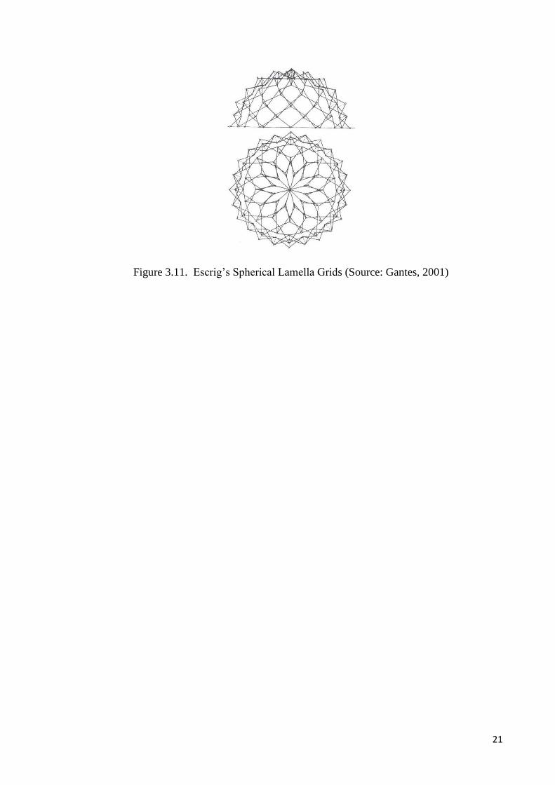
Felix Escrig Pallares is another researcher who was impressed by Pinero's work.
Escrig’s works are based on Piñero’s principle. He has worked on cover materials
identified that flexible materials are just useful for reduced spans and they don’t
contribute to structural strength. He developed deployable vault by incorporating rigid
plates which overlaps one another (Figure 3.10). Escrig has also developed several
models on pantographs and designed a swimming pool in Seville by utilizing one of his
models (spherical lamella grids) on pantographs (Figure 3.10, Figure 3.11).
Figure 3.10. Escrig’s deployable vault by incorporating rigid plates. (Source: Gantes,
2001)
21
Figure 3.11. Escrig’s Spherical Lamella Grids (Source: Gantes, 2001)

22
Figure 3.12. a) Model of a Selffolding roof hanging fabric (Source: Escrig et al., 1996)
b) The Photo of the deployable roof for San Pablo Swimming Pool
(Source: Escrig ,2013)
a
b
23
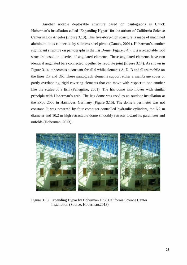
Another notable deployable structure based on pantographs is Chuck
Hoberman’s installation called ‘Expanding Hypar’ for the atrium of California Science
Center in Los Angeles (Figure 3.13). This five-story-high structure is made of machined
aluminum links connected by stainless steel pivots (Gantes, 2001). Hoberman’s another
significant structure on pantographs is the Iris Dome (Figure 3.4.). It is a retractable roof
structure based on a series of angulated elements. These angulated elements have two
identical angulated bars connected together by revolute joint (Figure 3.14). As shown in
Figure 3.14, α becomes a constant for all θ while elements A, D, B and C are mobile on
the lines OP and OR. These pantograph elements support either a membrane cover or
partly overlapping, rigid covering elements that can move with respect to one another
like the scales of a fish (Pellegrino, 2001). The Iris dome also moves with similar
principle with Hoberman’s arch. The Iris dome was used as an outdoor installation at
the Expo 2000 in Hannover, Germany (Figure 3.15). The dome’s perimeter was not
constant. It was powered by four computer-controlled hydraulic cylinders, the 6,2 m
diameter and 10,2 m high retractable dome smoothly retracts toward its parameter and
unfolds (Hoberman, 2013) .
Figure 3.13. Expanding Hypar by Hoberman.1998.California Science Center
Installation (Source: Hoberman,2013)

24
Figure 3.14. Hoberman’s element, formed by identical angulated rods (Source: You &
Pellegrino, 1997)
Figure 3.15. Iris Dome (Hoberman 1991) 2000’s World Fair, Hannover, Germany
(Source: Hoberman,2013)

25
Figure 3.16. Hoberman’s Arch (Source: Hoberman,2013)
A group called Deployable Structures Laboratory (DSL) within Cambridge
University directed by Dr. Sergio Pellegrino focused on scissor structures in the late
1980’s. Hoberman’s pioneering idea on angulated element led Pellegrino and Zhong
You to investigate the general conditions of pantographic deployable ring structures.
They investigated a new, large family of foldable building blocks, which are called
generalized angulated elements. These elements maintain a constant angle during
folding just like Hoberman’s angulated elements, but they afford greater freedom than
all other elements previously used. Also, they have discovered that a series of
continuous angulated rods can be replaced by a single, multi-angulated rod, reducing
the number of components of the structure (Gantes, 2001). Therefore, the structure
shown in Figure 3.17 consists of 24 bars, each having four segments with equal link
angles: 12 bars are located in a clockwise direction and 12 anti-clockwise. At each
crossover point, there is a revolute joint and it has the ability to retract radically towards
the perimeter and can be generated for various plan shapes.

26
Figure 3.17. Deployable multi-angulated bar by You and Pellegrino (Source: Korkmaz,
2004)
Langbecker is another researcher who improved Hoberman’s angulated units
and designed synclastic and anticlastic deployable structures with many angulated or
polar units (Figure 3.18). In order to increase stiffness and deployability feature, he
added numerous rigid units and joints to his design. On the contrary, these numerous
rigid units and joints made the structure more complex and expensive to fabricate and
the compact volume of the design increased (Langbecker, 2003).
Figure 3.18. Deployable double curvature scissor hinge structures by Travis Langbecker
(Source: Langbecker, 2003)
Tom Van Mele’s (2008) dissertation is about scissor-hinge structural
mechanisms. Mele (2008) worked on several case studies. Figure 3.19 shows his scissor
hinged retractable roof over a sports facility. His design requires additional retractable
supportive elements like a strut, an arch or a frame. These supportive struts are
necessary because in his system, the scissor-arches are cut in half and in the closed
configuration these ‘halves’ are connected at a central hinge. To avoid a permanent

27
structure that remains over the area even when the roof is open, each of the ‘half’
scissor-arches should be supported by a moveable supporting structure .The
intermediate configuration of the system is cantilever, so the deployable supportive
structures bear the cantilever part of the design (Mele, 2008).
Figure 3.19. Tom Van Mele’s visualization for retractable membrane roof (Source:
Mele, 2008)
3.2.1.2 Deployable Structures Based on 2-D Panels
Deployable structures based on 2-D panels are foldable structures. The basic
element of foldable structures is triangular panel. Foster & Krishnakumar (1986)
presented a family of foldable, portable structures which are based on the Yoshimura
buckle pattern for axially compressed cylindrical shells (Figure 3.20) (Gantes, 2001). In
this structure; in the basic triangular panel, one angle must be at least 90˚ and all
elements in the section must have the same shape and equal apex angles. Each module
must be capable of folding to a flat, compact form and these modules are joined with
continuous hinges from the parallel sides in order to form the complete structure.

28
Figure 3.20. Basic Layout of Foster’s module (Source: Gantes 2001)
With appropriate combinations of modules, structures with a large clear span are
possible. As the apex angle increases, the clear width and headroom also increase even
though the length of the erected module decreases and the number of elements and
hinges increase. Another important feature of foldable structures is that, as the number
of folds increases, the load bearing capacity of the structure increases too (Gantes,
2001).
Figure 3.21. Deployable Structures Based on 2-D Panels (Source: Gantes 2001)
Guest (1994) and Pellegrino (1994) have focused on deployable structures and
folding principles of triangulated cylinders. They had generated proposals such as
triangular foldable cylinders, wrapping fold pattern and solid surface deployable
antenna. Foldable cylinders are new way of packaging cylinders. All cylinders made of
isosceles triangles fold down to prisms. With this principle, it is possible to obtain
various kinds of deployable cylinders (Figure 3.22) (Gantes, 2001).

29
Figure 3.22.Triangulated foldable cylinders by Guest and Pellegrino (Source: Gantes
2001)
The “Kinetic Design Group” in the leadership of Michael A. Fox has developed
projects and applications for kinetic designs in MIT (Gantes, 2001). They have
applications as kinetic shading wall systems, kinetic partitioning wall systems,
architectural accessories and lightning, furniture. They have folding sheet structures that
can be an example for deployable structures based on 2-D panels (Figure 3.23). These
structures are prototypes which can shed light to various possible configurations of
deployable structures like exterior shelter, interior partitions or furniture (Gantes, 2001).
Figure 3.23. Half-shell with 3 Triangulated panels by “Kinetic Design Group”
(Source:Fox & Yeh, 1999)
Kinetic origami structures are on the agenda among deployable structures and
they can be regarded as deployable structures based on 2-D panels. These structures can
be applied to kinetic structures as retractable roofs, openings, temporary shelters and
space structures. Transformable polyhedral surfaces with rigid facets, i.e., rigid origami,
are useful for designing kinetic and deployable structures. Several designs of rigid-
origami structures have been proposed since 1970’s (Tachi, 2010). Tachi (2010) worked

30
on origami structures and he mentions that actual designs of architectural space with
origami have been unachieved because there is lack of design ability in the existing
methods. Therefore, he works on alternative methods on origami structures and
computational design of origami. He claims that dynamic property of origami structures
forms continuous surfaces unlike truss structures and scissor structures. And also, this
continuity preserves transformation (Tachi, 2010). Tachi (2010) works on plate-and-
hinge model of origami, which is called Rigid Origami. In rigid origami each rigid
panel is connected to adjacent panel with rotational one axis hinge. Thus, panels do not
deform and the system provides watertight cover for a space. In addition, Tachi (2010)
mentions that rigid origami is applicable for self deployable structures and large
architectural scale objects under gravity by using thick panels. He uses rigid origami by
generalizing rigid foldable structures to shapes like cylinders and more. Figure 3.24 and
Figure 3.25 show Tachi’s design. He has designed a foldable space to connect
temporarily the openings of existing two separate buildings having different sizes and
orientations.
Figure 3.24. Perspective view of Tachi’s design (Source: Architizer, 2012)

31
Figure 3.25. Tomohiro Tachi’s design to connect existing buildings (Source: Architizer,
2012)
You (2007) has devised origami structures to make common engineering
structures foldable. With the help of origami techniques and geometrical analysis You
have successfully developed a few concepts allowing thin-walled cylinders to be
shortened to a small package by introducing folding patterns on their surfaces (Figure
3.26) (You, 2012).

32
Figure 3.26. Bi stable foldable tubes (Source: You, 2012)
Deployable structures based on 2D panels can be a subject for art pieces as well
as architecture. İlhan Koman is a Turkish sculptor and he is renowned with his
nonfigurative static and kinetic works that gather art and science. He focuses on
geometrical forms. He has worked on polyhedra and discovered a foldable polyhedron
that is not rigid, having 10 vertices and 16 equal triangular faces (Figure 3.27). “I
considered that light-weight foldable construction elements based on such a polyhedron
might have application in engineering structures to be erected in space.” (Koman İ. &
Ribeyrolles F., 1979, p.1).
Figure 3.27. Koman’s foldable polyhedron (Source: Koman, 2011)

33
3.2.1.3 Cable-Membrane and Pneumatic Deployable Structures
Cables and membranes are proper materials for deployable structures due to
their fundamental characteristics. One of the main characteristics of cable-membrane
structures is that they have no stiffness against the perpendicular loads (Figure 3.28).
There is a substantial displacement between beam and a cable structure. The large
displacements may result in significant change of the geometry. But it is possible to
increase the stiffness of the cable-membrane structure like using pre-stressing or they
may acquire stiffness via their connection to cables and other, stiffer elements.
Figure 3.28. Displacement of beams and cable structures
Cable-membrane structures have both advantages and disadvantages. From the
historical point of view, the designing process of cable-membrane structures is complex
but with the help of technology, designing process of cable-membrane structures is not
complex with advanced computer simulation programs. Another difficulty regarding
these structures is manufacturing of them because cable-membrane structures are
manufactured from industrial textiles which are produced in rolls. Maybe,
manufacturing problem increase the labor cost of the structure but it doesn’t make the
structure insoluble. On the other hand, cable-membrane structures have vital advantages
like they have self-adaptability for earthquakes.
The best-known traditional example for cable-membrane systems are ‘toldos’
(spanish: awning). These traditional cotton awnings are still used to provide shade in the
streets of Spanish suburbs. They can be moved from the houses, roofs or street with
simple rope mechanisms (Figure 3.29) (Otto & Rasch, 1995).

34
Figure 3.29. Traditional toldos providing shade in the streets of Cordoba,Spain (Source:
Otto & Rasch, 1995)
German architect and research engineer Frei Otto, focused on lightweight tent-
like structures (Figure 3.30). He designed a series of retractable fabric coverings
controlled by cables. Adaptable architecture is the focal point of Frei Otto’s career. He
is interested in buildings that can be altered or simply dismantled (Nerdinger, 2005). He
supports the necessity of adaptable structures with his following words;
Static persistence is unnatural. Both dead and living nature change. No one
here doubts the validity of so-called static architecture. It is our daily
handwork, our usual method of building. We are familiar with historically
changeable, adaptable methods of construction (…) adobe buildings, the
tents, dry brick, the wagon barricade, military and civilian camps (…) and we
have mobile architecture. (…) Then we have convertible architecture, namely
the tent roof, tents, shells, lightweight structures. Convertible architecture
already has its place among the many architectures of the future. (Nerdinger,
2005, p. 31)

35
Figure 3.30. Frei Otto’s sketches; umbrellas and blinds as possible additive, convertible
canopies (Source:Nerdinger, 2005)
Frei Otto designed a convertible roof for Bad Hersfeld in 1968. The structure has
a central mast which stands by the nave of the ruin and it is guyed by two cables at the
rear and fourteen guy ropes running like rays over the nave. The roof can be in place
within four minutes and covers an area of 1315 square meters (Figure 3.31) (Otto &
Rasch, 1995).

36
Figure 3.31. Frei Otto’s convertible roof design for Bad Hersfeld in 1968 (Source: Otto
& Rasch,1995)
Bodo Rasch is a German architect and an engineer, who worked with Frei Otto.
Bodo Rasch has a similar cable membrane convertible roof design into the historical
castle for the open-air theatre in Wiltz in Luxemburg in 1988. The concept of this
design is the minimum intervention to the historical place. The designer aimed to
preserve the character of the place. The support structure of the roof runs around the
spectators and stage areas. The structure consists of tubular steel supports, guy ropes
and a ring rope. Folded membrane is parked in the area behind the spectators so it does
not interfere with their views. In bad weather, the roof is moved into place with the help
of mechanism and automatically gets its final position. The roof covers an area of 1200
square meters. The whole roof structure can be removed at the end of the theatre season
and then rebuilt without difficulty (Figure 3.32) (Otto & Rasch, 1995).

37
Figure 3.32. Cable membrane roof for the open-air theatre in Wiltz,Luxemburg by Bodo
Rasch ,1988 (Source: Otto & Rasch,1995)
Frei Otto founded Institute for Lightweight Structures at Stuttgart in 1964. One
of the designs of this institute is adapted to Multimedia Stadium for the Olympic
buildings in Munich in 1970 (Figure 3.33), even though there were no plans to put
design into practice. 180 meters long mast with 5-6 meters diameter had designed to
suspend the membrane which covers the 60,000 m² area and the cables run from the
head of the mast to 15 base points around the area.
Figure 3.33. Convertible Structure of Multimedia Stadium for the Olympic buildings
1970 (Source: Otto & Rasch, 1995)

38
Another deployable example for cable-membrane structure is the retractable roof
of Olympic complex in Montréal, Canada. The French architect Roger Tailibert
designed an Olympic complex for the Olympic Games in 1976. This complex
accommodates the ring-shaped stadium, the mast and the spherical vault of the
velodrome. The central playground and the race tracking field are covered by 20 000 m²
PVC/Kevlar folding membrane roof which is opened and closed by 28 stray cables
connected to 175 m inclined tower. This complex has become one of the Montréal’s
landmarks. Although, the stadium was opened in 1976 but retractable roof was finished
in 1988. The retractable roof replaced with a non-retractable spatial steel roof structure
in Olympic Stadium of Montréal, Canada (Figure 3.34) because complication occurred
in the case of the the stabilization of the membrane in all the possible configurations
(folded, during deployment, opened configuration). The membrane damaged due to
local failures and weather conditions (Holgate, 1997).
Figure 3.34. Olympic Complex in Montréal, Canada (Source: Taillibert, 2013)
Evidently, a more successful example for deployable membrane structures is the
membrane roof of the bullfighting area in Zaragoza, Spain (Figure 3.35). The area is
covered with a combination of a fixed and a convertible, central membrane roof. It is
designed by the German firm Scleich, Bergman and Partners in 1989. It is a light cable-
membrane structure with a fixed exterior ring supported by 32 radial cables. Only the
interior part of the roof is retractable. The area of the fixed roof is 4.400 m² and the area
of movable part is 1.000 m². The construction does not have any columns over a
diameter of 88 meter. The visitors enjoy the stunning spectacle of the unfolding and
opening process of the roof because takes only three minutes to unfold. This example is

39
a good one that proofs kinetic structure is an appropriate way to create exceptional
structures (Bergermann & Schlaich, 1992).
Figure 3.35. Retractable Roof for bullfighting area in Zaragoza, Spain. (Source:
Tensinet, 2012)
As aforementioned in the beginning of the current section (3.2.1.3), cable-
membrane structures have low stiffness. Prestressing is a method to increase their
stiffness. There is another group of membrane structures, which uses internal pressure
to control their stiffness characteristics called pneumatic structures. Probably, the
balloon is the most well-known basic pneumatic structure.
Pneumatic structures have natural deployability character due to their property
of controlling stiffness through pressure. Pneumatic structures are divided into two; 1)
air supported structures and 2) inflated structures (Figure 3.37). Air supported structures
consist of a single structural membrane, which is supported by a small air pressure
differential. The internal building volume is at a pressure slightly above atmospheric so
pressure differential occurs in and out of the building. On the contrary, in air inflated
construction, air is contained in a close membrane to form inflated structural elements,
such as walls, beams, arches, columns. Air inflated structures composed of small air
inflated structures inside and outside of the main structure. In inflated constructions,
loss of air pressure is less but periodic air replenishment is needed. The principles of
these structures are shown in Figure 3.36.

40
Figure 3.36. Principles of Air Supported and Air Inflated Membrane (Source: Gantes,
2001)
Figure 3.37. Fuji Group Pavilion EXPO ’70 Osaka, Japan; is an example for air inflated
membrane (Source: Tumblr, 2013)
Mush-balloon designed by Tanero Oki Architects for EXPO ’70 in Osaka,
Japan; is an example for kinetic air supported pneumatic structures (Figure 3.38). It is
an inverted shaped balloon, suspended by 45 wire ropes that pass from the top of a pole
through the center of the balloon. The balloon is made of an upper and lower fabric.
These fabrics are braced by inner ropes. Opening and closing process of the balloon
automatically has controlled by air pressure and ventilation system. But the most
appropriate control is to blow air in or vent it out, adjusting the pressure continuously,
accurately and keeping it within a range that would cause no deformation at all.

41
Figure 3.38. Mush-balloon designed by Tanero Oki Architects for EXPO ’70 in Osaka.
(Source: Tensinet, 2012)
3.2.1.4 Tensegrity Deployable Structures
Tensegrity is a fascinating concept developed by sculptor Kennet Snelson, and
later patented and explored by Buckminster Fuller (1962). The architect Fuller
pioneered that the method “tensegrity” could be applied to large architectural domes.
Fuller describes tensegrity as follows; “A tensegrity system is established when a set of
discontinuous compressive components interacts with a set of continuous tensile
components to define a stable volume in space.”(as cited inTibert, 2002, p.24). Hanaor
and Levy (1980) have a simple tensegrity definition as “In its purest form, a tensegrity
structure consists of a network of bars and cables, in which any bar is connected only to
cables and to no other bar” (Hanaor & Levy, 2001, p.218). Pugh’s (1976) definition as
follows; “A tensegrity system is established when a set of discontinuous compressive
components interacts with a set of continuous tensile components to define a stable
volume in space” (as cited inTibert, 2002, p.24).

42
Figure 3.39. Simple Tensegrity Structure with Three Compression Struts
Tensegrity structures have no redundant parts. As a consequence, they are
lightweight structures in comparison to other structures with similar resistance.
Tensegrity modules can be joined in order to create structural elements as beams,
columns. Tensegrity systems are self-anchored, however; they pull against themselves.
Such structures are self-stressed in a “closed” system (Robbin, 1996). Self stressing and
the load bearing capacity are directly proportional in tensegrity structures. If the self-
stressing capacity is higher, its load-bearing capacity is higher too. The flexibility and
the stiffness of the structure depend on the material employed and by their method of
assembly. To sum up, tensegrity structures have many properties. As a deployable
structure, tensegrity structures are practical because a small quantity of energy is needed
to change their configuration because its shape changes with the equilibrium of the
structure. Consequently, they are used in various kinds of deployable architectural
applications like shelter systems, domes, roof structures and towers. Tensegrity
structures can be used as installations, sculptures, furniture, toys and leisure applications
(Figure 3.40) besides architecture.

43
Figure 3.40. “Easy-K Installation” Snelson in 1970. Arnhem, (Holland) (Source:
Kennethsnelson, 2012)
David George Emmerich, is the the first to have pointed out the possibilities of
generating double-layer tensegrity grids (Robbin, 1996). Emmerich’s works motivated
researchers about tensegrity systems like René Motro. René Motro is the French
engineer and researcher and has studied tensegrity structures and folding tensegrity
systems (Figure 3.42). Deployment or folding is very promising application field for
tensegrity systems. Tensegrity systems can be folded and unfolded by modification of
element lengths. Length changes can be applied to both struts and cables. Many
different possibilities can be explored, depending on the designer’s choice (Motro,
2003). Tibert and Pellegrino (2003) also studied on deployable tensegrity masts (Figure
3.41). Hanaor (1980), an Israeli engineer has studied double-layer tensegrity grids and
the deployable examples in his research (Robbin, 1996).

44
Figure 3- 41 Physical model of Pellegrino’s folding mast at different stages of folding
process (Source: Tibert & Pellegrino, 2003)
Figure 3- 42 Réne Motro’s prototype of a double-layer, double-curvature tensegrity
system, continuous cables join the nodes (Source: Robbin, 1996)
Tensegrity structures had succesfully used as architectural elements in The
Prairie House. The Prairie House is a kinetic tensegrity system, designed by Tristan
d’estree Sterk who is the founding partner of a group called The Office for Robotic
Architectural Media & The Bureau for Responsive Architecture (Orambra) in
Northfield, Illinois (Figure 3.43).

45
Figure 3.43. “The Prairie House” Tristan d’estree Sterk in 2010.Northfield, Illinois
(Source: Orambra, 2012)
Figure 3.44. Actuated tensegrity prototypes. (Source: Orambra, 2012)
This group focuses on responsive architecture and interests in obtaining the art
of construction in a peculiar way by designing structures that can change its shape and
volume in order to prevent energy lost within the structure. These systems are
parametric structures and surfaces that are actuated with thermal memories. They
generate actuated tensegrity prototypes to use them in the projects like Prairie House
(Figure 3.44). It is claimed that Prairie house emits less than half of the carbon of a
typical house in Illinois because the house can change its shape and volume with its
actuated tensegrity structure (Ayres, 2012). In the hot weather, the volume of the house

46
expands to reduce the impact of internal heat loads conversely. In the cold days, it
shrinks itself to reduce heating requirements.
3.2.1.5 Retractable Roofs
Retractable roofs are roof structures that can transform from one configuration to
another (typically the open and closed roof) to provide variable cover to the space
underneath in response to changing conditions and/or functional requirements (Mele,
2008). In their closed configuration, retractable roofs remain rigid and do not fold; this
is the main distinguishing feature between retractable roofs and other types of
deployable structures. Retractable roofs are usually used for swimming pool enclosures
or other sports facilities. These systems have not only found their use in sport venues
but also at shipyards, exhibition and recreational spaces, greenhouses, shopping malls,
and for public spaces. Moreover, they are mainly used in climates with inclement
weather change to allow for playing of traditionally outdoor activities in more favorable
conditions. Although small-sized retractable roofs have existed for a long time, since
the 1930’s, the construction and worldwide spread of large size retractable roof systems
is only a recent phenomenon. The first systems were based on well-known crane
technology, soon to be followed by folding membranes, inspired by umbrellas and tents,
and telescopic systems. (Mele, 2008).
The retractable roof systems can be roughly classified into two according to their
coverings. The cladding of the structure should be made of flexible material like
membrane to be deployed from retracted or open position into a closed or extended
position to cover the area. Either, the cladding can be non-collapsible rigid frames or
panels. These panels are covered with rigid or flexile materials such as glass, plastics,
membrane materials, and metal plates. Therefore, opening and closing of these roofs
involves sliding, rotating, or folding of the panels. As well as, opening and closing
should be easy to operate by a few people. The structure should be safe in all three
configurations; open, closed and partially open. Horizontally moving systems are
popular since they easily fit rectangular swimming pools.
The Pittsburgh Civic Arena, or Mellon Arena, in the United States is known as
the earliest example of wide-span retractable roofs that were built according to crane
technology in 1958-1961 (Figure 3.45). The arena was designed by Mitchell & Ritchey.

47
The retractable roof panels rotate and overlap each other, with their central pivot
supported by an external cantilevered beam (Mele, 2008).
Figure 3.45. Pittsburgh Civic Arena in the United States in 1958-1961 (Mele, 2008)
The Ocean Dome in Miazaki, Japan is the world’s largest indoor water park
with its world’s largest fully retractable roof. The maximum opening of the roof is 100
m by 180m. The structure of the roof contains four sections and each section is 51.5
meter wide and 110 meter long and weighs 700 tons (Figure 3.46). Several projects of
this type realized in Japan like Fukuoka stadium by the Takenaka Corporation, with a
total floor space of 176.000 m², a retractable roof structure with three spherical steel
segments and a parallel lamellar truss system, seven floors above ground (Gantes,
2001). The first successful retractable roof in America was in the Toronto Skydome
with its three-panel, steel roof available for use in bad weather. It was designed by Rod
Robbie and the retraction time is twenty minutes (Gantes, 2001).

48
Figure 3.46. Ocean Dome Miazaki City, Japan (Gantes, 2001)
Except horizontal solutions, radial rotational systems are using to enclose
circular areas. These radial systems have a circular pillar and the whole system moves
around it. Figure 3.47. shows the radial rotating principle of these systems.
Figure 3.47. Radial rotating principle (Source: Gantes, 2001)
3.2.2 Pellegrino Classification
Prof. Sergio Pellegrino is a specialist in structural mechanics. He founded the
deployable structures laboratory in 1990 within University of Cambridge in order to
develop novel concepts of deployable and adaptive space structures. He did not propose

49
a clear classification; he grouped deployable structures in the book called “Deployable
Structures” which he edited from his courses and lectures.
The majority of the titles in Pellegrino’s book do not contain architectural
applications. Consequently, they are not related with the present dissertation. For
instance, coiled rods have been extensively used for spacecrafts, to deploy and retract
scientific instruments and solar arrays. Flexible shells are also in the same way, they are
not related with architecture, and they are for space applications. Pellegrino grouped
retractable tension structures, retractable roofs, pre-stressing membranes in the title of
“membrane”. This title consists of architectural samples, like retractable tension
structures are commonly used for canopies and awnings.
Figure 3.48. Pellegrino’s classification of deployable structures. (Source:
Pellegrino,2001)
Structural mechanisms; “deployable structures that belong to the mechanisms
category are assemblies of ‘rigid’ parts connected by movable joints, arrange in such a
way that the transformation from a packaged configuration to a deployable
configuration is possible.” (Pellegrino, 2001, p:16). Structural mechanisms contain
pantographs which are mentioned in Gantes’ classification. For structural mechanisms,
retractable hardtop of the cars is a good example from automotive industry.

50
Figure 3.49. Retractable hardtop of the car; is an example for structural mechanisms
(Source: Bmw, 2013)
Unlike Gantes, Pellegrino evaluated ring-like pantographs as a special group.
These structures are commonly used as deployable antennas. Tension truss antenna and
rigid-panel structures are both serving for space applications. Rigid-panel structures are
also used for solar arrays to generate electrical power. The last title in Pellegrino’s
classification is retractable dome. Hoberman’s Iris Dome which was discussed in
Gantes’ classification is the significant one as an example for a retractable dome.
3.2.3 Hanaor Classification
Ariel Hanaor is a civil engineer who had worked on space trusses in his doctoral
research at the University of Melbourne, Australia. He had also focused on space
structures, structural analysis, tensegrity systems and concrete technology. Prof. Robert
Levy is a researcher in the civil engineering department and he had focused on
geometrically nonlinear shell structures, fabric structures, optimal seismic control of
buildings, structural optimization.
Hanaor and Levy (2001) have a different approach towards deployable
structures in their common paper called “Evaluation of Deployable Structures for Space
Enclosures”. This paper contains a comprehensive classification of deployable
structures. According to their view, in deployable structures morphological aspects and
kinematic properties are significant and they build the context of deployable structures.
They composed a classification chart (Figure 3.50) for deployable structures and in their
chart the columns represent the morphological aspects of the structures such as the
structure is lattice or skeletal and continuous or stressed-skin structures. In skeletal
structures, the primary load-bearing structure consists of discrete members; whereas in
continuous structures the covering itself performs the load-bearing function. The rows
in the chart represent the kinematic properties. They mentioned that the kinematic

51
property of deployable structures is related to deployment technology. Kinematic
properties are divided into two subcategories; the ones with rigid links such as bars,
plates and the ones with deformable components. The deployable structures with
deformable components lack of flexible stiffness such as cables or fabric.
Lattice bar structures comprise three major parts, double layer grids, single layer
grids and spine. Structures based on scissors or pantographic grids are the most widely
investigated configurations in the literature. They also divide into subtitles as peripheral
scissors, radial scissors, angulated scissors and so on. Except scissors and pantographs,
lattice bar structures contains bar structures as ruled surfaces, articulated joints and
reciprocal grids. Reciprocal grids are essentially domical surfaces consisting of
mutually supported beams. Strut-cable systems are deployable structures with
deformable components. It can be claimed that strut-cable systems as tensegrity systems
that were mentioned in Gantes’ classification. The other deformable group in Hanaor’s
classification is tension membrane systems. This group possesses two sub-groups;
fabric structures which require a surface of negative Gaussian curvature (saddle shape)
and pneumatic structures which use air pressure to prestress the membrane in order to
obtain stiffness.

52
Figure 3.50. Deployable Structure classification chart by A.Hanaor and R.Levy (Source:
Hanaor & Levy, 2001)

53
3.2.4 Korkmaz Classification
Koray Korkmaz is an associate professor who works on kinetic structures and
their potentials within the Department of Architecture in Izmir Institute of Technology,
Turkey. Korkmaz had constituted a classification chart in his PhD thesis called “An
Analytical Study of the Design Potentials in Kinetic Architecture” according to
Kronenburg’s kinetic architecture definition. “Kinetic architecture is defined generally
as buildings, or building components with variable location or mobility and/or variable
geometry or movement” (as cited in Fox, 200, p:12).
According to Kronenburg’s definition he divides kinetic architecture into groups
in terms of ‘time’. In that sense, Korkmaz grouped the structures into two. In the first
group named “Buildings with variable Location or mobility” action takes place before
using the structure. This primary action is necessary in order to obtain initial form of the
structure. Portable, relocatable and demountable structures belong to this group. In the
second group called “Buildings with variable geometry and movement” the action takes
place after the initial architectural form of the structure is obtained. In other words,
structure contains a continuous movement.
Then Korkmaz created sub-divisions according to structures’ materials. (Figure
3.51) For instance, buildings with variable geometry and movement consist of soft
formed and rigid formed structures. Soft forms of structures are created with flexible
space-enclosing materials such as membranes that are transformed by shoving, twisting,
pushing or pulling. Rigid forms of building are those that are converted by sliding,
folding or rotating structural elements. Rigid forms of structures still group into two as
bar structures and surface structures. Additionally, linkage mechanisms differ from each
other with their cover materials; the ones with flexible cover materials and the others
with rigid cover materials.

54
Figure 3.51. Major Classification of Kinetic Architecture (Source: Koray Korkmaz,
2004)
From Gantes’ classification cable-membrane structures like Frei Otto’s
convertible roof structures (Figure 3.30, Figure 2.31) are placed into the subtitle called
soft forms of structures in Korkmaz’s classification. Rigid forms of structures are bar
structures like pantographs in Gantes’ classification.
Frei Otto’s adaptable weather-protection umbrellas for Pink Floyd’s USA
concert tour in 1977 (Figure 3.52) is an example for rigid bar structures with flexible
cover materials. Frei Otto developed ten umbrellas that can be folded up and retracted
into the stage floor. The umbrellas are 4.5 meters in diameter, their height varies
between 2.5 and 4.4 meters, and total area covered is 128 m². The umbrellas were so
aesthetically attractive, the musicians decided to integrate them into their stage show, so
their appearance became a fixed element of the event (Nerdinger, 2005). The other
considerable example for rigid bar structures with flexible cover materials is the largest
convertible umbrellas that have been built so far for the two courtyard of the Prophet’s
Holy Mosque in Madinah, Kingdom of Saudi Arabia by Bodo Rasch and Frei Otto in
1995. Each courtyard has six umbrellas. These umbrellas are spanning 17 meters to 18
meters with a height of 14 meters in the open position. The umbrellas are open during
the day and close through the night so they contribute to the regulation of the climate in
the building (Figure 3.53, Figure 3.54).
Hoberman’s arches in Figure 3.15. or Hoberman’s Iris Dome covered with rigid
panels are examples for rigid bar structures with rigid materials. Chuch Hoberman’s Iris
Dome has enclosure created by covering angulated elements with rigid plates, which are
allowed to overlap in the retracted position (Figure 3.55) (Korkmaz, 2004).

55
Figure 3.52. Adaptable weather-protection umbrellas for Pink Floyd’s USA concert tour
in 1977 (Source: Nerdinger, 2005)
Figure 3- 53 Umbrellas in Madinad during opening process (Source: Otto & Rasch,
1995)

56
Figure 3- 54 Umbrellas in Madinad (Source:Otto & Rasch, 1995)

57
Figure 3.55. Iris dome covered with rigid panels (Source:Korkmaz, 2004)
3.3 Reconfigurable Structures
Mechanisms with multi-degree of freedom are called reconfigurable mechanisms
and these structures can offer wide range of form flexibility compared to deployable
structures. Reconfigurable structures are prefabricated structures that can be
transformed as structural mechanisms from a closed compact configuration to multiple
alternative expanded forms, in which they need external stabilization in order to become
stable and be able to carry loads.
Since 1990’s, reconfigurable mechanisms and robots are popular between
kinematicians and roboticians. So, architects and civil engineers must meet with
reconfigurable structures in the present century in order to get rid of deployable
structures’ limits. Reconfigurable structures can be designed to respond kinetically to
future changes and they ensure re-purpose functionality to the structures. Plus, they

58
enhance the resilience through alteration and just like deployable structures, they hasten
the construction process.
Kokawa’s (1995) expandable cable scissors arch (CSA) can be an example for
reconfigurable structures because of its continuously changing configuration (Figure 3-
57). This structure can change its geometry without changing the span length. It is a
new type of expandable structure with three hinged arch scissors and zigzag flexible
cables through pulleys with them. The changing form of the structure is controlled only
by winding up or winding back by a winch. The basic idea of Kokawa’s Cable Scissors
Arch (CSA) is shown in Figure 3.56.
Figure 3.56. Basic Idea of Kokawa’s expandable scissors (Source: Kokawa, 95)
Figure 3.57. Prototype of CSA (Source: Kokawa, 2012)

59
Inoue (2008) designed a movable arch. This arch structure comprises several
variable geometry trusses (VGT). These trusses have extendable members, fixed
members and hinges, as shown in Figure 3.58.
Figure 3.58. Basic Mechanism of VGT (Source: Inoue, 2008)
Inove (2008) explains VGT’s working principles as follows;
“When extendable members are extended simultaneously, the truss beam
was changed like a spring stretching from (a) to (b). When the extendable
members are extended alternately, the truss beam was changed to a circular
shape (c). Moreover, when they are extended optionally and their lengths are
controlled, the truss beam can be changed into any intended shape (d). Based
on the shape change of such a basic beam, the feasibility of shape change in
an actual building was examined. This has been applied to architectural
design and construction.”(Inoue, 2008 p: 172) (Figure 3.60).
Figure 3.59. Transformation of beam shape using VGT (Source: Inoue, 2008)
Inoue and his colleagues have applied VGT to a spatial truss structure and
designed an attractive, unique monument for EXPO 2005 in Japan. Its shape could be
changed variably and irregularly (Figure 3.60). The shape of the monument changes

60
according to the performance patterns. On the other hand, Variable Geometry Truss is
not feasible as a building component because numerous actuators are needed to realize
the movement.
Figure 3.60. Movable Monument at EXPO 2005 designed by Inoue and his colleagues
(Source: Inoue 2008)
Akgün (2010) criticized the previous scissor hinge structures in his doctoral
dissertation and proposed a novel transformation model for deployable scissor hinge
structures in order to overcome the shortcomings of previous examples.
He aimed to achieve remarkable shape transformations with minimum numbers
of actuators and increase the feasibility of scissor-like elements. In his dissertation, he
noticed that Kokawa’s structure can’t transform to asymmetrical shape. Therefore, he
modified scissor-like element by attaching additional revolute joints on the bars. This is
called M-SLE. In this way, he enhanced the transformation ability of the structure.
Transformation ability depends on the number of M-SLEs, the number of SLEs and M-
SLEs and support points. So, he increased the possibilities of potential configurations.
His structure fixed from the both sides to the ground or to the appropriate surfaces of a
building and its span length is constant, just like Kokawa’s expandable cable scissors.
The proposed structure can be both spatial and planar. Akgün first found M-SLE for the
planar version. The planar version of the structure can constitute various curvilinear
geometries (Akgün, 2010) (Figure 3.61). Then he designed spatial module shown in
figure 3.62.

61
Figure 3.61. Akgün’s Proposed planar scissor-hinge and its elements (Source: Akgün
2010)
Figure 3.62. Akgün’s Proposed planar scissor-hinge and its elements (Source: Akgün,
2010)
Akgün had proposed a roof structure which can offer both flat and curvilinear
forms without changing the span length. He ensured the curvilinear form with the help
of his proposed modified scissor like elements. Then he designed spatial module shown
in Figure 3.63.

62
Figure 3.63. Proposed planar scissor-hinge structure as an adaptive roof (Source:
Akgün, 2010)

63
CHAPTER 4
CURVED SURFACES
The surfaces derived from curves commonly arise in architecture because curved
surfaces are more resistant than planar structures. Furthermore they are aesthetically
well-structured; the best example of this is Félix Candela’s thin shell structures.
There are lots of classifications for the geometry of curved surfaces. Türkçü
gives place to a classification of Curt Siegel in his book (Türkçü, 2009) (Figure 4.1). In
this classification, the shape of the profile curve is taken into consideration and curved
surfaces are divided into three groups; single curvature structures, double curvature
structures and freeform surfaces.
Figure 4.1. Curt Siegel (1972)’s classification (Source: Türkçü, 2009)
In order to describe structures according to their curvatures, some terms must be
mentioned. As a matter of fact, in most cases the shape of the profile curve heavily
influences the final shape of the emerging surface. The profile curves are called
principal curvature and in differential geometry, the Gaussian curvature or Gauss
curvature of a point on a surface is the product of the principal curvatures (Wikipedia,
2012). In simplest way, curvatures called k1 and k2 in Figure 4.2. are the “principal

64
curvatures” of the hyperboloid. The product K: k1 x k2 of principal curvatures is
“Gaussian curvature”.
Figure 4.2. Principal Curvatures; k1 and k2
4.1 Single Curvature Surfaces
In single curvature structures Gaussian curvature is always zero because the
principal curvature of k1 is a straight line and k2 is a curve. Cylinder, cone, truncate
cone are single curvature geometric forms with zero Gaussian curvature (Figure 4.3).
Figure 4.3. Examples of Single Curvature Surfaces.

65
4.2 Double Curvature Surfaces
Gaussian curvature of all points of double curvature surfaces are different from
absolute zero, it varies as minus (-) or plus (+) (Türkçü, 2009). Except cylinder and
cone, all rotational surfaces are double curvature surfaces. According Siegel’s
classification; double curvature surfaces are divided into two groups as ‘synclatic
surfaces’ and ‘anticlastic surfaces’.
4.2.1 Synclastic Surfaces
Synclastic surfaces’ Gaussian curvature is positive (+) and according to the
generation method they are classified into two groups; they can be generated either by
rotation or translation. Tangent planes that are drawn to all synclastic surfaces (both
rotational and translational) do not cut off these surfaces. This is not true for anticlastic
surfaces. Tangent planes cut the surfaces into several parts in anticlastic surfaces
(Türkçü, 2009).
Elliptic paraboloid is a translational synclastic surface (Figure 4.4.). Elliptic
paraboloid is generated by translating a parabola along another parabola. Both
generating parabolas have to be open to the same side and must have parallel axes. The
axis of an elliptic paraboloid is the intersection of the two symmetry planes (Pottmann,
2007).
Figure 4.4. Elliptical paraboloid is a translational synclastic surface (Source: Pottmann,
2007)
Sphere, paraboloid, ellipsoid, two-sheet rotational hyperboloid, torus are
rotational synclastic surfaces (Figure 4.5.). Rotating a circle about any of its diameters

66
produces a sphere. Rotational synclastic surfaces, especially sphere and spherical pieces
are commonly used in architecture. ‘Dome’ which has a great importance in architecture
is the architectural term for sphere. A rotational paraboloid arises by rotating a parabola
about its axis. Paraboloid is also a suitable form for dome structures. For example, St.
Peters Church in Vatican, Florence Catedral of Brunellesci, St. Paul Catedral in London
possess parabolic domes (Türkçü, 2009). It is possible to generate two-sheet rotational
hyperboloid by rotating a hyperbola about its major axis. And two types of ellipsoids
can be generated, first one is oblate rotational ellipsoid generated by rotating the ellipse
about its minor axis. The second one called prolate rotational ellipsoid. For the second
type of ellipsoid, it is possible to rotate the generating meridian ellipse about its major
axis. The Reichstag dome by Norman Foster in Berlin is an example for ellipsoid in
architecture; it has the shape of half a rotational ellipsoid (Figure 4.6). Torus can be
generated by rotating a circle about an arbitrary line. An industrial building for Walloon
Branch of Reproduction Forestry Materials in Marche-en-Famenne by Samyn and
Partners features a part of a torus and the shape of the TGV railway station in Avignon
was obtained by the intersection of two ring tori (Figure 4.7) (Pottmann, 2007). As a
summary, every synclastic surfaces are useful and important basic elements of many
architectural design processes.
Figure 4.5. Examples of rotational synclastic surfaces (Source: Pottmann, 2007)

67
Figure 4.6. The Reichstag Dome in Berlin by Norman Foster (Source: Pottmann, 2007)
Figure 4.7. a) TGV railway station in Avignon b) An industrial building in Marche-en-
Famenne by Samyn and Partners (Source: Pottmann, 2007)
a b

68
4.2.2 Anticlastic Surfaces
Anticlastic surfaces’ Gaussian curvature is negative (-). According to the
generation method, they are classified into three groups, rotational surfaces,
translational surfaces and ruled surfaces. As shown in Figure 4.8, rotational anticlastic
surfaces are one sheet hyperboloid, torus and catenoid.
Figure 4.8. Examples of rotational anticlastic surfaces (Source: Pottmann, 2007)
The one-sheet rotational hyperboloid is a rotational surface resulting from a
conic section being rotated about one of its axes (Pottmann, 2007). Parts of one-sheet
rotational hyperboloids are commonly used in architecture and design. In architecture
they can be seen widely as cooling towers and water storages. Metropolitan cathedral
designed by Oscar Niemeyer and Joaquim is an example for one-sheet rotational
hyperboloid in architecture (Figure 4.9).
Figure 4.9. Metropolitan Cathedral in Brasilia 1959-1970 (Source: Architectureabout,
2013)

69
Prior to the description of the catenoid, it is good to look at the definition of the
term catenary. “It is the equilibrium shape attained by an idealized rope (homogeneous,
completely flexible, and not flexible) under the influence of gravity.” (Pottmann, 2007
p.652) (Figure 4.10). A catenoid is a three-dimensional surface made by rotating
a catenary curve about its directrix (Wikipedia, 2012) (Figure 4.8).
Figure 4.10. The shape of the catenary. (Source: Pottmann, 2007)
Translational anticlastic surfaces are hyperbolic sections (saddle shaped
surfaces) and hyperbolic paraboloids. Hyperbolic paraboloids, also called as hypars, can
be generated as a ruled and translational surface. For example, in Figure 4.11 there is a
hyperbolic paraboloid which is generated by translating a parabola along another
parabola. Every cross section of hyperbolic paraboloid surface is a saddle shaped, in
other words they are hyperbolic sections. Hyperbolic sections can be generated as ruled
and translational surface like hypars (Figure 4.12). These special forms of translational
and ruled surfaces are seen widely in architecture and design.
Figure 4.11. A hyperbolic paraboloid which is generated by translating a parabola along
another parabola (Source: Pottmann, 2007)

70
Figure 4.12. Hyperbolic sections (Source: Pottmann, 2007)
4.2.2.1 Anticlastic Ruled Surfaces
One-sheet hyperboloids , hyperbolic paraboloids, conoids are anticlastic ruled
surfaces. Ruled surfaces can be generated by moving a generatrix and the most
prominent property of ruled surfaces is that their generatrix is always a straight line. In
order to generate a ruled surface, one generatrix (straight line) and two directrices are
necessary. The directrices position on separate planes. One end of the generatrix is on
one of the two directrices and the second end always positions on the other directrice.
The generatrix sweeps the directrices by rulings with the same ratio distances, which is
the method of generating a ruled surface. The directrices can be a point, a straight line, a
circle or a curve. Another property of ruled surfaces is that they always extend to
infinity because the generating straight lines extend to infinity. It is possible to create
remarkable ruled surfaces with special choices of directrices and their parameterization.
The designers have freedom to choose the directrices and the parameterization, this
technique leads a wide diversity of possible shape.
Conoids are ruled surfaces which can be generated by moving a straight line
segment along a directrix curve and a line. In other words, the first directrix of the
conoids is always a straight line and the second directrix is a curve (Figure 4.13). Parts
of the conoids are commonly used for design of shells or shed roofs. Allowing only
rotations about the directrix, it is possible to generate a special type of conoid (Figure
4.14).

71
Figure 4.13. Conoid- 1st directirice – straight line, 2
nd directrice – curve
Figure 4.14. Special type of conoid (Source: Pottmann, 2007)
The New State Gallery which is designed by James Stirling has ruled surface
facades which are generated by using two arbitrary curves as directrices (Figure 4.15).
Furthermore, The Japanese Art and Technology Center’s roof consists of ruled surfaces
that are generated by arbitrary curves as directrices (Figure 4.16).
Figure 4.15. The New State Gallery (1977-1983) in Stuttgart by James Stirling (Source:
Pottmann, 2007)

72
Figure 4.16. The Japanese Art and Technology Center in Krakow, Poland, by Arata
Isozaki (Source: Pottmann, 2007)
Hyperbolic paraboloids are one of the most used ruled surfaces in architecture,
especially in the area of shells. They are easy-to-use architectural elements and offer a
wide range of design possibilities. Hyperbolic paraboloid is a ruled surface which has
convex one way along and the concave along the other. Hyperbolic paraboloid (HP) can
be obtained as a ruled surface by sweeping a straight line over a straight path at one end
and another non-parallel straight path (Pottmann, 2007). The boundaries, or edges, of
the hyperbolic paraboloid can be straight or curved (Figure 4.17.). In Figure 4.18., HP
ruled surface is obtained by sweeping the lines ab and dc, these lines are divided with
the same ratio dist (a,p) /dist (p,b) = dist (d,q)/dist(d,c).
Figure 4.17. The boundaries, or edges, of the hyperbolic paraboloid can be straight or
curved (Source: Pottmann, 2007)
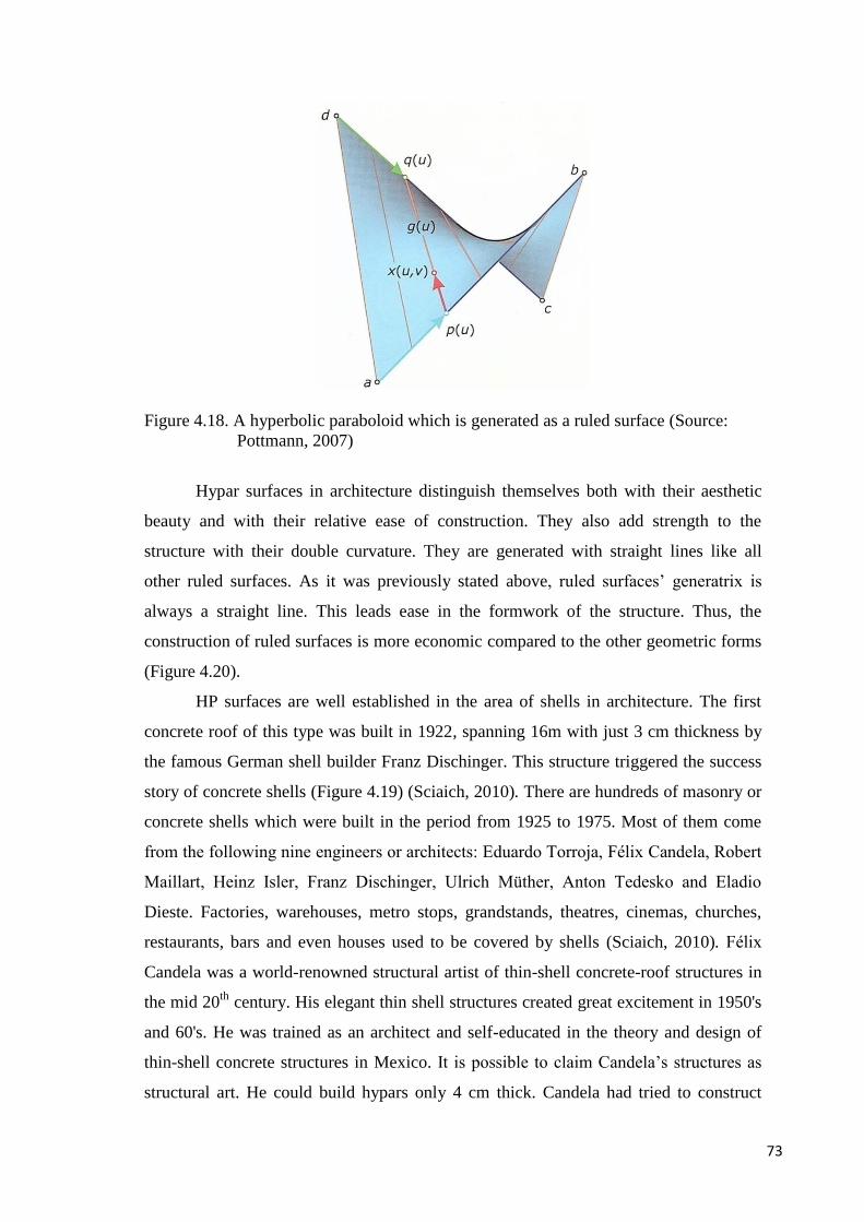
73
Figure 4.18. A hyperbolic paraboloid which is generated as a ruled surface (Source:
Pottmann, 2007)
Hypar surfaces in architecture distinguish themselves both with their aesthetic
beauty and with their relative ease of construction. They also add strength to the
structure with their double curvature. They are generated with straight lines like all
other ruled surfaces. As it was previously stated above, ruled surfaces’ generatrix is
always a straight line. This leads ease in the formwork of the structure. Thus, the
construction of ruled surfaces is more economic compared to the other geometric forms
(Figure 4.20).
HP surfaces are well established in the area of shells in architecture. The first
concrete roof of this type was built in 1922, spanning 16m with just 3 cm thickness by
the famous German shell builder Franz Dischinger. This structure triggered the success
story of concrete shells (Figure 4.19) (Sciaich, 2010). There are hundreds of masonry or
concrete shells which were built in the period from 1925 to 1975. Most of them come
from the following nine engineers or architects: Eduardo Torroja, Félix Candela, Robert
Maillart, Heinz Isler, Franz Dischinger, Ulrich Müther, Anton Tedesko and Eladio
Dieste. Factories, warehouses, metro stops, grandstands, theatres, cinemas, churches,
restaurants, bars and even houses used to be covered by shells (Sciaich, 2010). Félix
Candela was a world-renowned structural artist of thin-shell concrete-roof structures in
the mid 20th
century. His elegant thin shell structures created great excitement in 1950's
and 60's. He was trained as an architect and self-educated in the theory and design of
thin-shell concrete structures in Mexico. It is possible to claim Candela’s structures as
structural art. He could build hypars only 4 cm thick. Candela had tried to construct

74
significant, slender, aesthetic structures as well as economical and efficient structures;
this approach had made his reputation. As candela explained:
But an efficient and economical structure has not necessarily to be ugly. Beauty has no
price tag and there is never one single solution to an engineering problem. Therefore, it
is always possible to modify the whole or the parts until the ugliness disappears. This
aversion to ugliness is quite the opposite of the task of the professional artist who has to
produce beauty as an obligation or of today’s star-architect who has to be original at any
cost in each project. (cited in, (Garlock & Billington, 2010, p. 131)
The first hypar structure built by Candela was The Cosmic Rays Pavilion, built
on the campus of the Universidad Nacional Autónoma de Mexico (UNAM) in 1951
(Figure 4.21). This is only 1.5 centimeters thickness and is one of the thinnest structures
ever built. Furthermore, Candela had tried different combinations of hypars. For
example, in the design of Bacardi Rum Factory’s roof, he used three adjacent
hyperbolic paraboloids (Figure 4.22).
Figure 4.19. The first concrete shell structure designed by Franz Dischinger in 1922.
(Source: Cassinello, 2010)

75
Figure 4.20. Straight formwork of Chapel Lomas de Cuernavaca (1958) (Source:
Tectonicablog, 2010)
Figure 4.21. The Cosmic Rays Pavilion in Mexico,1951. Felix Candela’s first hypar
structure. (Source: Cassinello,2010)
Figure 4.22. Bacardi Rum Factory (1960). (Source: Billington & Garlock, 2010)

76
Candela aimed to achieve structural equilibrium in shells and in other structures
and this nearly always meant symmetry (Margolius, 2002). He did not use computers to
analyze or design hypar structures, but instead he used membrane theory in his designs.
He used both straight edges and curved edges hypars to create his designs. The church
of Our Lady of the Miraculous Medal (1955), Restaurant Los Manantiales (1958),
Chapel Lomas de Cuernavaca (1958) (Figure 4.23), Bacardi Rum Factory (1960) are the
major works of Félix Candela. Félix Candela had pioneered an era with his elegance
and resistant hyperbolic-paraboloid shell structures. Today, almost all his innovative
structures are landmark structures.
Figure 4.23. Chapel Lomas de Cuernavaca (1958) (Source: Billington & Garlock, 2010)
On the other hand, Candela’s slender concrete shell structures do not belong to
today’s architecture. First of all, they became out of fashion and difficult to analyze.
They are not appropriate for big spans. Candela was convinced that spans of more than
30 meters were not economical (Sciaich, 2010). Moreover, they are dark structures
which mean they are opaque and do not permit light to enter the space below. For
natural light, openings are required but they make them even more difficult to analyze.
In addition, shells are not compatible with modern building physics because the
reinforced concrete does not have a good thermal insulation. Also, insulation claddings
eliminate shell’s slenderness. They provided labor intensive formwork that makes shell
structures expensive because especially in the developing countries labor became more
and more expensive. As a summary, it is not feasible to construct dark concrete shells
today. Constructing hypars as light weight structures are mainly successful for special
purpose structures. For instance, Figure 3.24 shows glass hypar roof with plane

77
quadrangular glass panels. It is an elegance transparent light weight structure.
Nonetheless, today’s architecture needs more to make a difference.
Figure 4.24. Glass Hypar Roof, Schubert Club Band, Minneapolis, 2001. (Source:
Sciaich, 2010)
4.3 Freform Curved Surfaces
Freeform surfaces are complex surfaces and it is hard to define these surfaces
mathematically, but they offer much more flexibility. In architecture, only in the
nineteenth century architects started to use freeform surfaces in their expressions with
industrialization and improved building materials such as iron, steel, and reinforced
concrete. Antoni Gaudi (1852-1926) successfully used freeform surfaces in his
structures. His Sagrada Familia (1882- today) and the Casa Mila (1905-1907) (Figure
4.25) are the most prominent examples.
Figure 4.25. The Casa Mila (1905-1907) (Source: Zoomandgo, 2012)

78
In today’s architecture, designing freeform structures is much more possible
with the help of computer-aided geometric design (CAGD) technologies.
Freeform curved surface is hard to be defined mathematically just like freeform
surfaces. It is possible to shape freeform surfaces by a small number of control points. It
is important to master freeform curves because the solution of curves can trigger the
development of freeform surface modeling.
Bézier curves are the most widely used freeform curves. For the design of
complex curves, the more powerful B-spline curves which offer local shape control had
present. Nonuniform rational B-spline (NURBS) curves are used to draw most complex
planar and spatial freeform curves, as well as to draw all types of conic sections (Figure
4.26) (Pottmann, 2007) .
Figure 4.26. Types of freeform curves. (Source: Pottmann, 2007)

79
CHAPTER 5
MECHANISMS
Structure is made of several parts put together in a particular way so as to resist
to do impact of loads imposes on it. Kinetic structure is a collection of mechanisms
arrange to transmit forces and motion. Therefore, firstly mechanism should be defined
in order to understand kinetic structures.
Mechanism consists of several parts put together in a particular way that has the
purpose of transferring motion and force from a source to an output. Basically there are
three types of mechanisms. These are linkage mechanisms, gear mechanisms (Figure
5.4) and cam mechanisms (Figure 5.5). A linkage is particular type of mechanism
consisting of a number of interconnected rigid components, individually called links.
The connection between the links is called joint. The joints of the linkages are spherical
joint, planar joint, screw joint, revolute joint and prismatic joint. A linkage modeled as a
network of rigid links and ideal joints is called a kinematic chain. Linkages may be
constructed from open chains (Figure 5.3), closed chains (Figure 5.1), or a combination
of open and closed chains (Figure 5.2). When any link is fixed, the chain becomes
mechanism.
Figure 5.1. Closed loop linkage mechanism A, B, C and their kinematic diagram D.

80
Figure 5.2. Closed and open chain from nature (Source: Pellegrino, 2001)
Figure 5.3. a) Open chain-Kinetic Sculpture by Jeffery Laudenslager b) Kinematic
diagram of the sculpture (Source: Laudenslagersculpture, 2013)
Gears are links that are used, by means of successively engaging teeth, to
provide positive motion from a rotating shaft to another that rotates, or from a rotating
shaft to a body that translates. Gears can be classified as spur gears, bevel gears, helical
gears, and worm and worm gears (Yan, 1998).

81
Figure 5.4. Some types of gear sets (Source: Norton, 2004)
A cam is an irregular shaped link that serves as a driving member and imparts a
prescribed motion to a driven link called follower. Cams can be classified as wedge
cams, disk cams, cylindrical cams, barrel cams, conical cams, spherical cams, roller
gear cams, and others (Yan, 1998). The sculpture designed by Laikingland Yatzer in
Figure 5-6 is an example for cam mechanisms. In the sculptor, fingers represent the
followers so there are four cams and the input is the motor.
Figure 5.5. Cam mechanism (Source: Dawie-sutton,2012)

82
Figure 5.6. Cam mechanism- Designed by Laikingland Yatzer (Source: Yatzer, 2012)
5.1 Overconstrained Linkages
Overconstrained linkages are mechanisms which have special geometric
conditions among the links and joint’s axes. These are linkages that are connected only
by revolute joints. From classical mobility analysis, it is known that spatial linkages
should have at least seven links to be mobile (Chen, 2003). General mobility criterion
for mechanisms was established by Grübler (or Kutzbach) in 1921. According to this
criterion, mobility of a spatial linkage can be found with the equation shown below. In
the following equation n is the number of links and {pi}5
1 is number of joints having i
degree of freedom (DOF) of joints.
52321
5
1
12345)1(6
)6()1(6
pppppnM
pinMi
i
(5.1)
A closed loop linkage with n-link has same number of revolute joints. Therefore p1=n.
Then according above equation;
7
61
6
5)1(6
n
n
nM
nnM
(5.2)

83
Thus, to obtain a mobility of one, a spatial single loop linkage with only revolute
joints must have at least seven links. However, some mechanisms, which have specific
geometric condition in the assembly of its parts do not obey Grübler criterion. These are
overconstrained mechanisms with four, five or six links. They are exceptional
mechanisms that have full range mobility. Thereby, overconstrained mechanisms can be
define as distinct form; if a system of links and joints has mobility M=0 or less
according to Grübler criterion , yet still moves, then it is called an overconstrained
mechanism.
The first published research on over-constrained mechanisms is traced back to
150 years ago when Sarrus (1853) discovered his six-bar mechanisms (Figure 5.7).
Since then, various researchers have worked on other overconstrained mechanisms such
as Bennett (1903), Delassus (1922), Bricard (1927) (Figure 5.8.), Myard (1931),
Goldberg (1943), Waldron (1967, 1968 and 1969) Wohlhart (1987, 1991 and 1993) and
Dietmaier (1995). Philips (1984, 1990) summarized all of the known over-constrained
mechanisms in his two-volume book. The most detailed studies on over-constrained
mechanisms belong to Baker (1980.1984, etc.) (Chen, 2003). 3D single loop over-
constrained linkages can have four, five or six links. When these linkages consist of
only revolute joints, they are called 4R, 5R or 6R linkages.
Figure 5.7. 6R Sarrus Mechanism (Source: Chen, 2003)
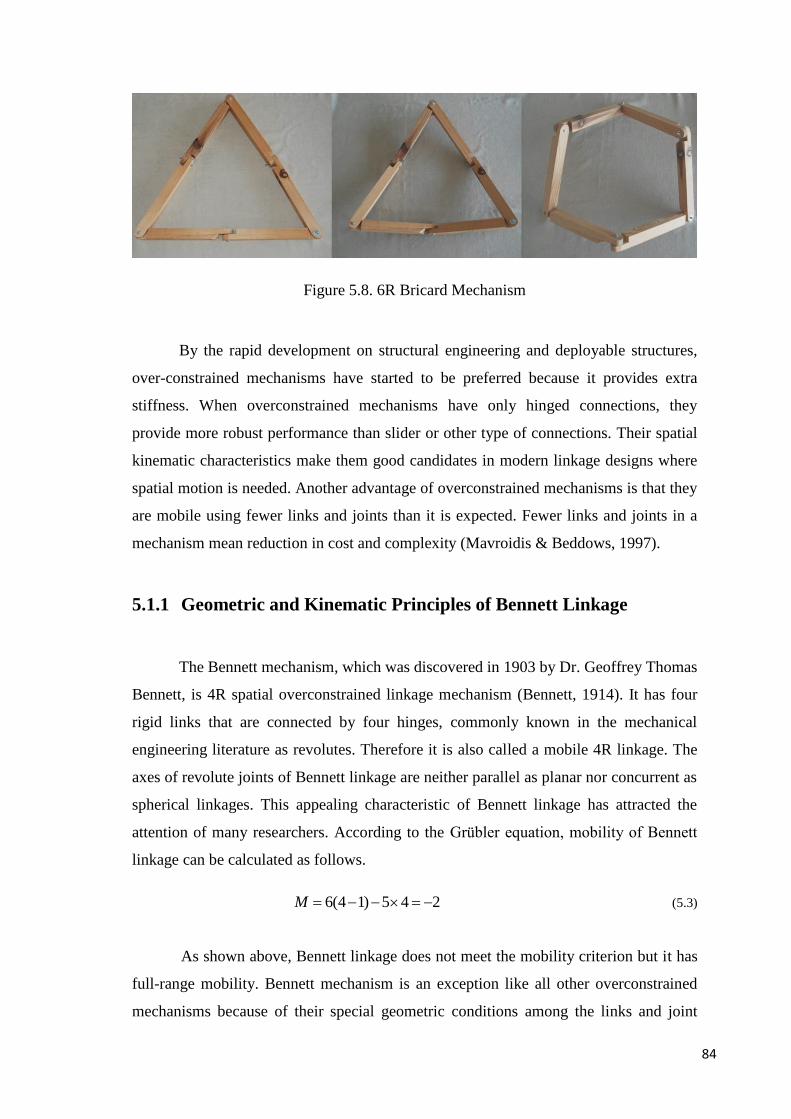
84
Figure 5.8. 6R Bricard Mechanism
By the rapid development on structural engineering and deployable structures,
over-constrained mechanisms have started to be preferred because it provides extra
stiffness. When overconstrained mechanisms have only hinged connections, they
provide more robust performance than slider or other type of connections. Their spatial
kinematic characteristics make them good candidates in modern linkage designs where
spatial motion is needed. Another advantage of overconstrained mechanisms is that they
are mobile using fewer links and joints than it is expected. Fewer links and joints in a
mechanism mean reduction in cost and complexity (Mavroidis & Beddows, 1997).
5.1.1 Geometric and Kinematic Principles of Bennett Linkage
The Bennett mechanism, which was discovered in 1903 by Dr. Geoffrey Thomas
Bennett, is 4R spatial overconstrained linkage mechanism (Bennett, 1914). It has four
rigid links that are connected by four hinges, commonly known in the mechanical
engineering literature as revolutes. Therefore it is also called a mobile 4R linkage. The
axes of revolute joints of Bennett linkage are neither parallel as planar nor concurrent as
spherical linkages. This appealing characteristic of Bennett linkage has attracted the
attention of many researchers. According to the Grübler equation, mobility of Bennett
linkage can be calculated as follows.
245)14(6 M (5.3)
As shown above, Bennett linkage does not meet the mobility criterion but it has
full-range mobility. Bennett mechanism is an exception like all other overconstrained
mechanisms because of their special geometric conditions among the links and joint

85
axes. The dimension of subspace is λ=3 (Korkmaz, Akgün & Maden, 2012). The
Grübler formula for subspace λ=3 gives:
142)14(3
2)1(3 1
xM
pnM (5.4)
Figure 5.9. Schematic representation of the Bennett Mechanism (Korkmaz, Susam &
Akgün, 2013)
The special geometric conditions of Bennett linkage are listed below as:
1) The skewed angles between the axes of two revolute at the ends of the links and the
lengths of the bars on opposite sides are equal.
4123
3412
4123
3412
baa
aaa
(5.5)
2) The twists and the lengths must satisfy the condition of
sinsin
ba (5.6)
3) The skewed angles α and β are restricted to the range (0,π ), the displacement
closure equations depends on four variable joint angles θi that provide below
conditions:
θ4
1
23
4
a23
a34
a41
α12
α23
α34
α41
a12
θ1
θ2
θ3

86
4231 2 (5.7)
)(2
1sin
)(2
1sin
2tan
2tan 21
(5.8)
These closure equations are only in use when one of the revolute variables θi is
independent. In addition to above conditions, there is a special case in which a different
type of Bennett linkage is generated (5.4). When α+β=π and a=b, an equilateral linkage
is obtained. Therefore, Eq. 5.7 becomes as;
cos
1
2tan
2tan 21 (5.9)
5.1.2 Deficiencies and Alternative Works on Bennett Linkage
Bennett linkage is a spatial mechanism which can constitute a deployable hypar.
But it has many geometric limitations. For instance, Bennett linkage neither can fully
close to a bundle nor can fully deploy to a flat surface. The revolute joints used in the
Bennett linkage are mechanically simple but their placement along each link and angle
between the pin axes are complicated.

87
Figure 5.10. Bennett Linkage (Source: Springerimages, 2013)
Notwithstanding, in the last ten decades many researchers studied on Bennett
Linkage in different fields. Perez and McCarty focused on the relation between Bennett
mechanism and cylindroids (Perez & McCarthy, 2002), Baker has established the
relationship between the ruled surface and the corresponding centrode of the Bennett
linkage’s planar form (Baker, 2001), Peilin Tian and Yan Chen devised a shelter and the
frame of the shelter is an assembly of 5 Bennett linkages (Figure 5.11) (Tian & Chen,
2010). Yan Chen tried different variations of Bennett Linkage in her doctoral thesis. She
focused on connectivity and the network of Bennett Linkages (Figure 5.12). (Chen,
2003) Chen and Baker published an article on using Bennett Linkage as a connector
between other Bennett loops (Figure 5.12) (Baker & Chen, 2005) (Yu, Luo, & Li,
2007).
Figure 5.11. A product design of the foldable shelter frame (Source: Chen, 2003)

88
Figure 5.12. (a) deployable arch made of Bennett network (b) Bennett Linkage as a
connector between other Bennett loops (Source: Chen, 2003)
Therewithal, Chen improved a novel joint detail in her dissertation for Bennett
mechanism. First of all Chen identifies basic element from Bennett linkage with skew
square cross-section bars to obtain compact folding and maximum expansion (Figure
5.13). With this particular example Chen shows that the construction of a Bennett
linkage with compact folding and maximum expansion is not only mathematically
feasible, but also practically possible. Figure 5.14 shows the geometry of the square
cross-section bar. As shown in the Figure 5.14 in geometry of the novel joint there are
parameters and it is hard to ensure these parameters (the angles that have to be satisfied
in Figure 5.14) at the practice. Plus, her design has single degree of freedom and cannot
ensure full form flexibility and adaptability like a reconfigurable structure.
Figure 5.13. Bennett linkage with skew square cross-section bars

89
Figure 5.14. The geometry of the square-cross section bar (Source: Chen, 2003)
Figure 5.15 shows a deployable structure with a membrane attached to it. Yang
Yu et al (2007) investigated the compatibility between the membrane and Chen’s
structure during the process of deployment. In order to identify the behavior of the
membrane, they first simplified the membrane with cable net layout with two main
directions perpendicular to each other. By this way length variations of the cables are
determined. The necessary geometric calculations had done to determine the limitations
to ensure the compatibility between the membrane and the linkage (Yu, Luo, & Li,
2007).

90
Figure 5.15. A deployable membrane structure in the folded and unfolded
configurations (Source: Yu, Luo, & Li, 2007)
5.2 Proposed 8R Reconfigurable Linkage Mechanism
Bennett linkage has limitations to offer flexible solutions. To obtain real flexible
solutions, the proposed mechanism must have 2-DOF with distinctive connection details
and additional links. The idea of novel mechanism originated from the simple models
seen in Figure 5.16. The models made with straws show three equilateral Bennett
linkages with same joint angle θ1. Even though these three linkages have same lengths
and same joint angles, their configurations are different. This is because of the different
skewed angles α and β for each linkage. Thus any linkage cannot transform to another
one. The skewed angles of the novel mechanism must be changeable. To reach this aim,
additional links 2, 3and 6,7 are connected with revolute joints as shown in Figure 5.17.
Four revolute joints between links 1and 2, 3 and 4, 5 and 6, 7 and 8 let rotations about
the links’ axes. Now skewed angles α12, α23, α34, α41 are changeable and the
mechanism can physically move with overlapped circular section links. It is easy to
realize the overlapped circular sections compared with Yan Chen’s skew square cross-
section bars. Furthermore, since M=2 both side of the mechanism can move
individually, and the system can transform from planar geometries to various hypars
(Korkmaz, Susam & Akgün, 2013).

91
Figure 5.18 shows shape alternatives of the proposed 8R linkage. Now the new
mechanism operates in λ=6. It can also stow and deploy completely. This shape
flexibility proves the superiority of the novel mechanism over Bennett Linkage.
Figure 5.16. Equilateral Bennett linkages with same joint angle θ1 but different skewed
angles α and β (Korkmaz, Susam & Akgün, 2013)
Figure 5.17. The proposed 8R reconfigurable linkage mechanisms (Korkmaz, Susam &
Akgün, 2013)

92
Figure 5.18. Transformation capacity of the proposed novel mechanism (Korkmaz,
Susam & Akgün, 2013)
Figure 5.19 Kinematic diagram of the proposed mechanism (Korkmaz, Susam &
Akgün, 2013)
Kinematic diagram of the novel mechanism is shown in shown in Figure 5.19.
According to Grübler’s criterion, the mobility of this novel mechanism is:
285)18(6
5)1(6 1
M
pnM (5.10)
This mechanism can be used as an adaptable building component (such as a roof,
1
2
3
4
5
67
8
C
D
A
B
R
R
R
R
R
R
R
R

93
façade system, or furniture, etc.) which can change its shape according to the
expectations of the users. In order to use this system as a roof structure, some
intermediate links would be necessary to attach the rigid cover materials for long span
architectural applications. But, the connection points of the intermediate links on
opposite sides of the linkage come closer during the deployment process. During the
deployment process each intermediate link must extend or shorten. Therefore, it is
impossible to attach one rigid straight rod to the linkage
Initially, the proposal for the intermediate links consists of two square section
links connected with prismatic joints which allow translation. The experimental studies
with prototypes have revealed that there is also rotation besides translation between the
two bars. Therefore, cylindrical joints that can let both rotation and translation are used
instead of prismatic joints between additional circular bars. Figure 5.20 shows the
kinematic diagram of the novel mechanism with intermediate links.
Figure 5.20 Kinematic diagram with intermediate links (Korkmaz, Susam & Akgün,
2013)
With the addition of the intermediate links the mechanism remains 2 DOF
because the additional intermediate links are structural groups. Structural groups have
zero mobility. Figure 5.21 shows the kinematic diagram of the structural group which
consists of two moveable links and three 2DOF joints.
03426
04)(6 2
xxM
pmM (5.11)
1
2
34
5
67
8
C
D
A
B
9
10 11
12
R
RR
R
R
2R
R
R
R
CC
C13
14
2R
2R
2R
2R
2R

94
In the above equation m is the number of moveable links, p2 is the number of 2
DOF joints.
Figure 5.21 Kinematic diagram of the structural group (Korkmaz, Susam & Akgün,
2013)
The whole system remains 2DOF with the additional structural groups. Now it
consists of 14 links, eight 1 DOF (R) joints and nine 2DOF (2R and C) joints. The
mobility of the new mechanism can be proved with the following Grübler equation.
29485)114(6
45)1(6 21
M
ppnM (5.12)
Figure 5.22 Representation of the new 2 DOF joint (Korkmaz, Susam & Akgün, 2013)
2R
C
2R
12

95
Figure 5.23. The model shows the transformation capacity of the novel mechanism with
fourteen intermediate links (Korkmaz, Susam & Akgün, 2013)

96
Figure 5.24. 2R and C joints of the model (Korkmaz, Susam & Akgün, 2013)

97
During the manufacturing process of the cover, it would be complicated to attach
any rigid panels to any intermediate link because of translation and rotation between the
two links. Connection details of the rigid panels must be solved properly; otherwise
panels can block the movement. Besides, bending moment on the intermediate links is
another problem. It can cause excessive friction because of the translation between the
two links. For that reason, a revision in the intermediate links is essential. In the revised
linkage, the cylindrical joint is relocated at the end of the intermediate link. The revised
additional link is again a structural group. Figure 5.25 shows the kinematic diagram of
the revised structural group which consists of one link, one 2DOF joint and one 4DOF
joint. The revised structural group has zero mobility again (5.13).
Figure 5. 25 Revised structural group with zero DOF (Korkmaz, Susam & Akgün,
2013)
0
121416
246 42
M
M
ppmM
(5.13)
In equation 5.13, m is the number of moveable links, p2 is the number of 2 DOF
joints, p4 is the number of 4 DOF joints.
C
2R
R
R
1

98
Figure 5.26. Representation of the new 4 DOF joint (Korkmaz, Susam & Akgün, 2013)
Figure 5.27. Revised kinematic diagram of the proposed mechanism (Korkmaz, Susam
& Akgün, 2013)
Figure 5.27. shows the kinematic diagram of the novel mechanism with new
intermediate links. With the addition of structural groups, the whole system remains
2DOF again. Now it consists of 11 links, eight 1 DOF (R) joints, three 2DOF (2R) and
three 4DOF (2RC) joints. The proof of the revised mechanism with Grübler equation as
2323485)111(6
245)1(6 421
M
pppnM (5.14)
As a result, this thesis has exposed a 2DOF 8R novel linkage mechanism based
upon Bennett mechanism. Firstly geometric principles of the 8R linkage mechanism,
then superiority over Bennett linkage have been explained. Finally, Bennett mechanism
1
2
34
5
67
8
C
D
A
B
910
R
RR
R
R
2R
R
R
R
C
11
2R
R
2R
R
C
R
R
C
RR

99
with extra structural groups yields a structural mechanism that takes various forms and
provides an adaptable space under it. The specific application considered is a roof
structure. It can provide an adaptable space under it. Contrary to single DOF deployable
structures, the proposed 2 DOF reconfigurable structure has wider form flexibility.
100
CHAPTER 6
CONCLUSION
This chapter offers the aforementioned contributions of the dissertation in the
development of reconfigurable hyperbolic paraboloid structures and highlights possible
future works.
In the context of this dissertation, the review of previous classifications and the
types of deployable structures have been thoroughly investigated. This part is requisite
because deployable structures form the fundamentals of kinetic structures. Therefore,
this investigation is essential in order to expose the deficiencies of the deployable
structures that have been created up to now. Deployable structures do not have full form
flexibility. This is the main shortcoming of deployable structures. Deployable structures
with various configurations are expressed as reconfigurable structures. In this way, the
possibilities of constructing a reconfigurable hyperbolic paraboloid structure which is
constructed by a novel mechanism built the objective of the present study. The novel
reconfigurable mechanism utilizes the overconstrained 4R Bennett linkage and the
production principals of ruled surfaces. In this respect, the present study is a pioneer
study on reconfigurable structures for architectural applications.
After the investigation of deployable structures, the main properties of curved
surfaces especially ruled surfaces are examined. Ruled surfaces particularly hypar
surfaces are common forms used in architecture as shell structures. But the existing
examples of hypar surfaces are stabile structures. In order to transform these static
hyperbolic paraboloid structures into reconfigurable ones, an investigation of
mechanisms is necessary. Hence, the present dissertation consists of a chapter on
mechanisms. The overconstrained 1 DOF Bennett mechanism is investigated
thoroughly. Geometric and kinematic principles of Bennett linkage are examined and
their shortcomings with respect to form flexibility are exposed. A novel 2 DOF 8R
spatial linkage mechanism has been proposed to overcome these shortcomings. The new
mechanism presents remarkable form flexibility from flat to double-curved hypar
shapes with new connection details. It can achieve these remarkable shape
transformations with two actuators. A reconfigurable deployable hypar structure has

101
been developed by the utilization of this novel mechanism. Furthermore, intermediate
links and their connection details are investigated. There are two different proposals for
intermediate links and their connections. The structure is analyzed with kinematic
diagrams and the models.
6.1 Further Research
In the context of this dissertation, the fusion of architecture and the mechanism
science ensured a creative expression for architecture. The proposed mechanism
presented in this dissertation can shed light on new future works. The proposed 2 DOF
8R linkage mechanism can open many possibilities of constructing reconfigurable
structure and more intensive research could be carried out on this issue.
The proposed mechanism can be used as an adaptable building component. The
present study handled the mechanism as a roof structure. More case studies can be done
with the proposed linkage. For example, assemblies of the proposed linkage can be a
subject for further studies. Networks of the proposed linkage in alternative forms can be
developed. It has led to discover many designs like façade systems or furniture designs.
Meanwhile, many other deployable linkage mechanisms such as architectural umbrellas
can be used as a building component as well. Further studies can concentrate on the
other linkage mechanisms and reveal novel transformable structures.
Actuators are the crucial elements of such kind of transformable deployable
structures. They provide both the motion and the stability of the whole system.
Location, type, and force of the actuators can be changed according to the geometric
and material properties of the structure. Thus, future studies should consider the
location and type of the actuators. One specific issue that needs more research is the
covering of the proposed linkage. The covering is important in order to ensure a real
architectural element with the proposed linkage. Therefore, the combination of the
proposed linkage with flexible materials, rigid plates which overlap one another or
origami type of covering, can be the subject of further research studies. In addition,
since the static analyses of the linkage are not within the scope of the present study,
static analyses of the linkage for further studies will be highly desira

102
REFERENCES
Akgün,Y., Gantes, C. J., Sobek, W., Korkmaz, K., & Kalochairetis, K. (2011). A novel
adaptive spatial scissor-hinge structural mechanism for convertible roofs.
Engineering Structures, 33(4), 1365-1376.
Akgün, A. (2010). A Novel Transformation Model For Deployable Scissor-Hinge
Structures. A dissertation submitted for the degree of Doctor of Philosophy, Izmır
Instıtue of Technology, Izmir, Turkey.
Ayres, P. (2012). Prairie House: House for a Fashion Pattern Maker and Fiber Artist-
Northfield, IL. Persistent Modelling Extending the Role of Architectural
Representation, Rougtledge Press. Retrieved from
http://www.orambra.com/~prairieHouse.html
Baker, J. (2001). The Axodes of the Bennett Linkage. Mechanism and Machine Theory,
36 ,105-116.
Baker, J. E., & Chen, Y. (2005). Using a Bennett linkage as a connector between other
Bennett Loops. Journal of Multi-Body Dynamics, 219, 177-185.
Bennett Linkage. n.d. Retrieved from March 15, 2012, from
http://www.springerimages.com/Images/ComputerScience/1-10.1007_978-0-
85729-811-9_11-5
Bennett, G. T. (1914). The Skew Isogram Mechanism.Proceedings of the London
Mathematical Society, 13(19), 151-173.
Bergermann, R., & Schlaich, J. (1992). Cable-Membrane Roof for the Area in
Zaragoza. Structural Engineering International, 2(4), 238-241.
Billington, D.P. ,& Garlock, M. E. M. (2010). Structural Art and the Example of Félix
Candela. Journal of Structural Engineering, 136(4), 339-342.
Cam Mechanisms. n.d. Retrieved from September 7, 2012, from
http://dawie-sutton.wikispaces.com/Mechanisms
Cam Mechanism designed by Laikingland Yatzer. n.d. Retrieved from September 7,
2012, from http://www.yatzer.com/Kinetic-Art-by-Laikingland
Catenoid. n.d. In Wikipedia. Retrieved from August 10, 2012, from
http://en.wikipedia.org/wiki/Catenoid
Chen, Y. (2003). Design of Structural Mechanisms. A dissertation submitted for the
degree of Doctor of Philosophy, University of Oxford, Oxford, UK.

103
Deployable Structure as an art piece, created by Lygia Clark called ‘Bichos’. (2013).
Retrieved March 15, 2013, from http://gaarq.blogspot.com/2012/08/carta-de-
lygia-clark.html
Drawbridge. (2012). Retrieved April 20, 2012, from
http://en.wikipedia.org/wiki/Drawbridge
Easy-K Installation. (2012). Retrieved May 25, 2012, from
http://www.kennethsnelson.net/sculpture/outdoor/9.htm
Engel, H. (1967). Structure Systems. London Lliffle Books Ltd, Germany.
Escrig, F. (2013). Modular ,Light and Transformable Architecture. In F. Escrig ,& J.
Sanchez (Eds.) , New Proposals for Transformable architecture.Engineering and
Design in the honor of Emilio Perez Pinero (pp.11-22). Seville: Starbooks.
Escrig, F., Valcarcel, J.P.,& Sanchez J. (1996). Deployable Cover on a Swimming Pool
in Seville. Journal of the International Association for Shell and Spatial
Structure: IASS, 37 (120), 39-70.
Expanding Hypar. (2013). Retrieved May 25, 2013, from
http://hoberman.com/portfolio/expandinghypar.php?myNum=12&mytext=Expand
ing+Hypar&myrollovertext=%3Cu%3EExpanding+Hypar%3C%2Fu%3E&categ
ory=&projectname=Expanding+Hypar
Fox, M.A., & Yeh, B.P. (1999). Intelligent Kinetic Systems. Retrieved from
http://citeseerx.ist.psu.edu/viewdoc/download?doi=10.1.1.124.4972&rep=rep1&t
ype=pdf
Fuji Group Pavilion EXPO ’70 Osaka. (2013). Retrieved May 25, 2013, from
http://expositionframes.tumblr.com/post/36506012853/fuji-group-pavilion-expo-
70-osaka
Gans, D. (1991). Bridging The Gap. New York: Van Nostrand Reinhold.
Gantes, C. J. (2001). Deployable Structures: Analysis and Design. Southampton: WIT
Press.
Gantes, C. J., Connor J. J., & Logcher R. D., (1994). A Systematic Design Methodology
for Deployable Structures. International Journal of Space Structures, 9 (2), 67-86.
Garlock, M. E., & Billington, D. P. (2010). Felix Candela's Legacy. In P. Cassinello et
al (Eds.), Felix Candela Centenario 2010 (pp.127-133). Madrid: Universidad
Politécnica de Madrid.
Gaussian curvature. n.d. In Wikipedia. Retrieved from August 10, 2012, from
http://en.wikipedia.org/wiki/Gauss_curvature
Guggenheim Museum. (2012). Retrieved September 11, 2012, from
http://www.guggenheim.org/new-york/collections/collection-online/artwork/5677

104
Hachem, C., Karni E., & Hanaor A. (2004). Deployable Structures in Nature:Examples,
Analysis and Realizations. IASS Symposium on Shell and Spatial Structures-From
Models to Realization, 45(3), 190-198.
Hanaor A., & Levy R. (2001). Evaluation of Deployable Structures for Space
Enclosures. International Journal of Space Structures, 16(4), 211-229.
Hoberman Arch. (2013). Retrieved May 25, 2013, from
http://hoberman.com/portfolio/hobermanarch.php?myNum=22&mytext=Hoberma
n+Arch&myrollovertext=%3Cu%3EHoberman+Arch%3C%2Fu%3E&category=
architecture&projectname=Hoberman+Arch
Holgate, A. (1997). The Art of Structural Engineering.Axel Menges, Stuttgart.
Retractable Roof for bullfighting area in Zaragoza. (2012). Retrieved May 20,
2012, from http://www.tensinet.com/database/viewProject/3793.html
İlhan Koman’s Foldable polyhedron. (2011). Retrieved November 15, 2011, from
http://www.koman.org/main/in_frame_works.ht
Iris Dome. (2013). Retrieved May 25, 2013, from
http://hoberman.com/portfolio/irisdome-
worldsfair.php?myNum=26&mytext=Iris+Dome&myrollovertext=%3Cu%3EIris
+Dome%3C%2Fu%3E&category=architecture&projectname=Iris+Dome
Inoue, F.(2009). A Study on Adaptive Arch Structure Applying Variable
Geometry Truss (Mechanism of Movable Arch Roof with External Panel).
Journal of Robotics and Mechatronic, 21(2),172-178.
Kinetic Sculpture by Jeffery Laudenslager. n.d. Retrieved from March 10, 2013, from
http://www.laudenslagersculpture.com/
Kokawa, T.(1995) A Trial of Expandable Arch. Proc.of IASS Symposium in
Milan,1,501-510.
Koleichuk, V. (1973). Self-Building Structure [photo]. National Gallery of Art ,
Lithuania.
Koman, İ., & Ribeyrolles, F. (1979). On My Approach to Making Nonfigurative Static
and Kinetic Sculpture. Pergamon Press, 12, 1-4. Retrieved from
http://www.koman.org/pub/pub_body_4.htm
Korkmaz, K., Susam G., & Akgün Y. (2013). A Novel 8R Mechanism for
Reconfigurable Hypar Surface. In F. Escrig ,& J. Sanchez (Eds.) , New Proposals
for Transformable architecture.Engineering and Design in the honor of Emilio
Perez Pinero (pp.77-82). Seville: Starbooks.
Korkmaz, K. (2004). An Analytical Study of the Design Potentials in Kinetic
Architecture. A dissertation submitted for the degree of Doctor of Philosophy,
Izmır Instıtue of Technology, Izmir, Turkey.

105
Korkmaz, K., Akgün,Y., & Maden, F. (2012). Design Of An 2-DOF 8R Linkage For
Transformable Hypar Structure. Mechanics Based Design Of Structures and
Machines: An International Journal, 40(1), 19-32.
Kronenburg, R. (2003). Transformable environments 2. London: Spon Press.
Kurg, A., & Mari, L. (2012). Our Metamorphic Futures [Exhibition].National Gallery
of Art, Lithuania.
Langbecker, T., & Albermani, F. (2003). Kinematic and non-linear analysis of foldable
barrel vaults. Engineering Structures, 23,158-171.
Lecture 23: Architectural Origami. Guest lecture by Tachi T., (August
12,2010)[video].Massachusetts: MIT 6.849 Geometric Folding Algorithms
Prof.Erik Demaine. Retrieved April 20,2013 from
http://courses.csail.mit.edu/6.849/fall10/lectures/L23.html
Margolius, I. (2002). Architect+Engineers:Structures.Chichester: John Wiley&Sons
Ltd.
Mavroidis, C., & Beddows, M. (1997). A Spatial Overconstrained Mechanisms.
Proceedings of the 5th Applied Mechanisms and Robotics Conference, Retrieved
May 12, 2012 from http://www.coe.neu.edu/Research/robots/papers/AMR97.pdf
Mele, T. V. (2008). Scissor-Hinged Retractable Membrane. A dissertation submitted for
the degree of Doctor of Philosophy, Vrije Universiteit Brussel, Brussel, Belgiumç
Metropolitan Cathedral in Brasilia. Retrieved May 25, 2013, from
http://architecture.about.com/od/findphotos/ig/Oscar-Niemeyer/Cathedral-of-
Bras-lia.htm
Moon, F. C. (2007). Introduction. Leonardo da Vinci and Franz Reuleaux: Machine
Engineers. Springer Netherlands.
Motro, R. (2003) Tensegrity: Structural Systems for the Future, London: Kogan
Page Science.
Movement-Kinetic Art. (2012). Retrieved September 11, 2012, from
http://www.guggenheim.org/new-york/collections/collection
online/movements/195405/description
Mush-balloon. (2012). Retrieved May 20, 2012, from
http://www.tensinet.com/database/viewProject/3839.html
Nerdinger, W. (2005). Frei OttoComplete Works. Berlin: Bırkhauser Verlag AG.
Norton, R. L. (2004). Design of Machinery : An Introduction to the Synthesis and
Analysis of Mechanisms and Machines. New York: The McGraw-Hill Companies.
Norton, R. L. (2004). Design of Mechanisms. New York: McGraw-Hill.

106
Olympic Complex in Montréal, Canada. (2013). Retrieved May 25, 2013, from
http://www.stadeolympiquemontreal.ca/le-toit-taillibert.aspx
Otto, F., & Bodo, R. (1995). Finding Form: Towards an Architecture of the Minima.
Fellbach : Editions Axel Menges.
Papadopoulos, E. (2007), Heron of Alexandria. In M.Ceccarelli (Ed.), Distinguished
Figures in Mechanism and Machine Science, Their Contributions and Legacies,
Book Series on History of Mechanism and Machine Science, pp. 217-245,
SpringerVerlag .
Pellegrino, S. (2001). Deployable Structures. New York: Springer.
Pellegrino, S., & Gan, W.W. (2003). Closed-loop deployable structures. 44th
AIAA/ASME/ASCE/AHS/ASC Structures, Structural Dynamics and Materials
Conference. Retrieved May 10,2012 from
http://www.pellegrino.caltech.edu/PUBLICATIONS/Closed-
Loop%20Deployable%20Structures%202003.pdf
Perez, A., & McCarthy, J. (2002). Bennett’s linkage and the cylindroid. Mechanism and
Machine Theory, 37(11) , 1245-1260.
Pfalzkeller Emergency Service Center. (2012). Retrieved November 8, 2012, from
http://www.miestai.net/forumas/showthread.php?p=148824&langid=1
Pinero, E. (1961) A Reticular Movable Theater. The Architect' Journal, 299.
Pottmann, H., Asperl, A., Hofer, M., & Kilian A. (2007). Architectural geometry.
Pennsylvania, USA: Springer & Bentley Institute Press.
Prototype of Cable Scissors Arch (CSA). (2012). Retrieved May 20, 2012, from
http://t-kokawa.com/index.html
Razaz, Z. E. (2010). Sustainable vision of kinetic. Journal of Building Appraisal , 5(4),
341-356.
Retractable hardtop of the car. (2013). Retrieved May 25, 2013, from
http://www.bmw.in/in/en/newvehicles/mseries/m3convertible/2008/allfacts/design
/retractable_hardtop.html
Robbin, T. (1996). Engineering a New Architecture. Massachusetts: Quebecor-Eusey
Press.
Sciaich, M. (2010). Thin concrete shells and other light-weight double-curved
structures. In P. Cassinello et al (Eds.), Felix Candela Centenario 2010 (pp. 111-
123). Madrid: Universidad Politécnica de Madrid.

107
Sorguç, A.G., Hagıwara I., & Selçuk S.A. (2009). Origamics in Architecture: A
Medium of Inquiry for Design in Architecture. Journals Middle East Technical
University, METU JFA, 26(2), 235-247.
Straight formwork of Chapel Lomas de Cuernavaca. (2010) Retrieved May 25, 2013,
from http://tectonicablog.com/?p=20045
Tachi, T. (2010). Geometric Considerations for the Design of Rigid Origami Structures.
Proceedings of the International Association for Shell and Spatial Structures
(IASS) Symposium. Retrieved April 20,2013 from
http://www.tsg.ne.jp/tT/cg/DesignOfRigidOrigamiStructures_tachi_IASS2010.pdf
The Casa Mila.n.d. Retrieved from August 15, 2012, from
http://www.zoomandgo.com/destinations/image_viewer.asp?dak=61131415
The Prairie House. (2012). Retrieved May 25, 2012, from
http://www.orambra.com/~prairieHouse.html
The Roman amphitheatres’ removable tension roof of canvas. (2013). Retrieved
February 17, 2013, from http://fineartamerica.com/featured/colosseum-awning-
granger.html
Tian, PL., & Chen, Y. (2010). Design of a Foldable Shelter. The International
Symposium of Mechanism and Machine Theory, AzCIFToMM – Izmir Institute of
Technology, Izmir, Turkey
Tibert, A.G.(2002). Deployable Tensegrity Structures for Space Applications. A
dissertation submitted for the degree of Doctor of Philosophy, Royal Institute of
Technology Department of Mechanics. Stockholm, Sweden.
Tibert, A.G., Pellegrino S. (2003). Deployable Tensegrity Masts. In Proc. 44th
AIAA/ASME/ASCE/AHS/ASC Structures, Structural Dynamics, and Materials
Conference, 7-10 April 2003, Norfolk, VA AIAA 2003-1978. Retrieved from
http://www.pellegrino.caltech.edu/PUBLICATIONS/Deployable%20tensegrity%
20masts%202003.pdf
Tibert, A.G., & Pellegrino S. (2003). Review of Form-Finding Methods for Tensegrity
Structures. International Journal of Space Structures, 18(4), 209-223.
Tillberg, M. (2007). Cybernetics and Arts: The Soviet Group Dvizhenie 1964-1972.
Retrieved August 10, 2012 from
http://www.mediaarthistory.org/replace/replacearchives/tillberg_abstract.ht
Tomohiro Tachi’s design. (2012) Retrieved May 12,2012, from
http://architizer.com/projects/rigid-foldable-origami-gallery/
Türkçü, H. Ç. (2009). Çağdaş Taşıyıcı Sistemler. İstanbul: Birsen Yayınevi.
Yan, H.S. (1998). Creative Design of Mechanical Devices. Singapore: Springer-Verlag
Singapore Pte.Ltd.

108
You, Z. (2012). Motion structures. Retrieved November 12, 2012, from http://www-
civil.eng.ox.ac.uk/people/zy/research/origami.html
Yu, Y., Luo, Y., & Li, L. (2007). Deployable membrane structure based on the.
J.Aerospace Engineering , 221, 775-783.
You, Z., Pellegrino S. (1997). Foldable Bar Structures. Int.J. Solids Structures, 34 (15),
1825-1847.
Zuk, W., & Clark, R. H. (1970). Kinetic Architecture. Canada: Van Nostrand Reinhold
Ltd.

![[library.iyte.edu.tr] - İYTE Kütüphanesi - Ana Sayfalibrary.iyte.edu.tr/tezler/master/makinamuh/T000515.pdf · 2012-01-05[library.iyte.edu.tr] - İYTE Kütüphanesi - Ana Sayfa](https://static.fdocuments.net/doc/165x107/5ab633697f8b9a1a048d927e/-iyte-ktphanesi-ana-sayfa-iyte-ktphanesi-ana-sayfa.jpg)