A Real-time Augmented Reality Surgical System for...
10
A Real-time Augmented Reality Surgical System for Overlaying Stiffness Information Nicolas Zevallos*, Rangaprasad Arun Srivatsan, Hadi Salman, Lu Li, Jianing Qian, Saumya Saxena, Mengyun Xu, Kartik Patath and Howie Choset Robotics Institute, Carnegie Mellon University, 5000 Forbes Avenue, Pittsburgh, PA 15213. *Email: [email protected] Abstract—We describe a surgical system that autonomously searches for tumors and dynamically displays a computer graphic model of them super-imposed on the organ (or in our case, phantom). Once localized, the phantom is tracked in real time and augmented with overlaid stiffness information in 3D. We believe that such a system has the potential to quickly reveal the location and shape of tumors, and the visual overlay will reduce the cognitive overload of the surgeon. The contribution of this paper is the integration of disparate technologies to achieve this system. In fact, to the best of our knowledge, our approach is one of the first to incorporate state-of-the-art methods in registration, force sensing and tumor localization into a unified surgical system. First, the preoperative model is registered to the intra-operative scene using a Bingham distribution-based filtering approach. An active level set estimation is then used to find the location and shape of the tumors. We use a recently developed miniature force sensor to perform the palpation. The estimated stiffness map is then dynamically overlaid onto the registered preoperative model of the organ. We demonstrate the efficacy of our system by performing experiments on a phantom prostate model and other silicone organs with embedded stiff inclusions using the da Vinci research kit (dVRK). I. I NTRODUCTION Robot-assisted minimally invasive surgeries (RMIS) are becoming increasingly popular as they provide increased dexterity and control to the surgeon while also reducing trauma, blood loss and hospital stays for the patient [23]. These devices are typically teleoperated by the surgeons using visual feedback from stereo-cameras, but without any haptic feedback. This can result in the surgeon relying only on vision to identify tumors by mentally forming the correspondence between intra-operative view and pre-operative images such as CT scans/MRI, which can be cognitively demanding. Automation of simple but laborious surgical sub-tasks and presenting critical information back to the surgeon in an intuitive manner has the potential to reduce the cognitive over- loading and mental fatigue of surgeons [8]. This work lever- ages the recent advances in force sensing technologies [15], tumor localization strategies [1, 2, 28], online registration techniques [32, 33, 34] and augmented reality [24] to automate the task of tumor localization and dynamically overlay the information on top of intraoperative view of the anatomy. While there are works in literature that deal with force sensing [25, 37], force-based exploration [29, 31, 39, 40], da Vinci Research Kit Stereo Camera Force Sensor Prostate Phantom Needle Driver Tool Fig. 1. Experimental setup showing the dVRK robot with a miniature force sensor attached to the end-effector. A stereo camera overlooks the workspace of the robot. A phantom prostate with embedded stiff inclusion is placed in the workspace of the robot. tumor localization [1, 2, 5, 7, 8, 28] and graphical image overlays [30, 35, 36, 41], there is a gap in literature when it comes to systems that deal with all these issues at the same time. For example, Yamamoto et al. [41] deal with tumor localization and visual overlay, but they assume the registration is known, the organ is flat and place the organ on a force sensing plate, which is not representative of a realistic surgical scenario. On the other hand, Garg et. al. [8] use a palpation probe mounted on a da Vinci research kit (dVRK) tool (This probe was originally developed by McKinley et. al. [18]). However, they do not deal with registering the organ or visual overlay of the estimated stiffness map. The work of Puangmali et. al. [25] (and many others as noted by Ti- wana et. al. [37] in their review paper) deal with development of miniature force sensing technologies for minimally invasive surgeries, but they do not discuss strategies to palpate or ways to perform image overlay of the estimated stiffness map. Ayvali et. al. [1, 2] and Salman et. al. [28] develop techniques to smartly palpate a tissue and search for tumors
Transcript of A Real-time Augmented Reality Surgical System for...

A Real-time Augmented Reality Surgical Systemfor Overlaying Stiffness Information
Nicolas Zevallos*, Rangaprasad Arun Srivatsan, Hadi Salman, Lu Li,Jianing Qian, Saumya Saxena, Mengyun Xu, Kartik Patath and Howie Choset
Robotics Institute, Carnegie Mellon University,5000 Forbes Avenue, Pittsburgh, PA 15213.
*Email: [email protected]
Abstract—We describe a surgical system that autonomouslysearches for tumors and dynamically displays a computer graphicmodel of them super-imposed on the organ (or in our case,phantom). Once localized, the phantom is tracked in real time andaugmented with overlaid stiffness information in 3D. We believethat such a system has the potential to quickly reveal the locationand shape of tumors, and the visual overlay will reduce thecognitive overload of the surgeon. The contribution of this paperis the integration of disparate technologies to achieve this system.In fact, to the best of our knowledge, our approach is one of thefirst to incorporate state-of-the-art methods in registration, forcesensing and tumor localization into a unified surgical system.First, the preoperative model is registered to the intra-operativescene using a Bingham distribution-based filtering approach. Anactive level set estimation is then used to find the location andshape of the tumors. We use a recently developed miniatureforce sensor to perform the palpation. The estimated stiffnessmap is then dynamically overlaid onto the registered preoperativemodel of the organ. We demonstrate the efficacy of our systemby performing experiments on a phantom prostate model andother silicone organs with embedded stiff inclusions using the daVinci research kit (dVRK).
I. INTRODUCTION
Robot-assisted minimally invasive surgeries (RMIS) arebecoming increasingly popular as they provide increaseddexterity and control to the surgeon while also reducingtrauma, blood loss and hospital stays for the patient [23].These devices are typically teleoperated by the surgeons usingvisual feedback from stereo-cameras, but without any hapticfeedback. This can result in the surgeon relying only on visionto identify tumors by mentally forming the correspondencebetween intra-operative view and pre-operative images suchas CT scans/MRI, which can be cognitively demanding.
Automation of simple but laborious surgical sub-tasks andpresenting critical information back to the surgeon in anintuitive manner has the potential to reduce the cognitive over-loading and mental fatigue of surgeons [8]. This work lever-ages the recent advances in force sensing technologies [15],tumor localization strategies [1, 2, 28], online registrationtechniques [32, 33, 34] and augmented reality [24] to automatethe task of tumor localization and dynamically overlay theinformation on top of intraoperative view of the anatomy.
While there are works in literature that deal with forcesensing [25, 37], force-based exploration [29, 31, 39, 40],
da Vinci Research Kit
Stereo Camera
Force Sensor
Prostate Phantom
NeedleDriverTool
Fig. 1. Experimental setup showing the dVRK robot with a miniature forcesensor attached to the end-effector. A stereo camera overlooks the workspaceof the robot. A phantom prostate with embedded stiff inclusion is placed inthe workspace of the robot.
tumor localization [1, 2, 5, 7, 8, 28] and graphical imageoverlays [30, 35, 36, 41], there is a gap in literature whenit comes to systems that deal with all these issues at the sametime. For example, Yamamoto et al. [41] deal with tumorlocalization and visual overlay, but they assume the registrationis known, the organ is flat and place the organ on a forcesensing plate, which is not representative of a realistic surgicalscenario. On the other hand, Garg et. al. [8] use a palpationprobe mounted on a da Vinci research kit (dVRK) tool (Thisprobe was originally developed by McKinley et. al. [18]).However, they do not deal with registering the organ orvisual overlay of the estimated stiffness map. The work ofPuangmali et. al. [25] (and many others as noted by Ti-wana et. al. [37] in their review paper) deal with developmentof miniature force sensing technologies for minimally invasivesurgeries, but they do not discuss strategies to palpate orways to perform image overlay of the estimated stiffnessmap. Ayvali et. al. [1, 2] and Salman et. al. [28] developtechniques to smartly palpate a tissue and search for tumors

with a small number of probings. The work of Chalasani et. al.[5, 7] provides an alternate way of palpation by probingalong continuous trajectories. However, these works do notdeal with graphically overlaying the estimated stiffness mapand also use an ad hoc force sensing set up consisting of aplate mounted on a commercial force sensor. The work ofSanan et. al. [29] and Srivatsan et. al. [31] uses force-basedexploration for registration and stiffness estimation, but theydo not perform image overlay and spend a lot of time probingthe entire organ in a raster-scan pattern. Finally the workof Wang et. al. [39, 40] uses force controlled exploration toperform deformable registration to preoperative model of theorgan, but they do not estimate the stiffness of the tissue orperform graphical image overlay. The work in this chapteraims to bridge these shortcomings and present a unified systemcapable of addressing all the above mentioned issues at thesame time.
The system of Naidu et. al. [21] comes closest to our work.They use a custom designed tactile probe (developed by Tre-jos et. al. [38]) to find tumors and visually overlay the tactileimage along with the ultrasound images. The wide tactile arraythat they use, allows for imaging sections of the organ insteadof obtaining discrete measurements, as in our case. Thiseliminates their need to develop sophisticated tumor searchalgorithms. However, as acknowledged by Trejos et. al. [38],it is not clear as to how their system would perform when usingnon-flat organs such as prostates and kidneys; since the tactilearray cannot deform and confirm to the shape of the organ.Without performing registration, the image overlay would alsobe affected on non-flat organs.
The framework presented in this paper is robot agnostic andmodular in nature. We demonstrate the efficacy of the systemby performing autonomous tumor localization on a phantomprostate model and other custom fabricated flat silicone organswith embedded tumors using the dVRK platform [14] (seeFig. 1). There are two reasons for choosing the dVRK fordemonstration – (1) it is a good representation of a surgicalrobot, (2) there are several research groups across the worldthat use dVRK and we hope they will all benefit from the workpresented in this paper. A miniature force sensor mountedat the tip of the dVRK needle driver tool (developed byLi et. al. [15]) is used to sense the contact forces. An active tu-mor search strategy developed by Salman et. al. [28] is used tolocalize the tumor. The estimated stiffness map is overlaid on aregistered model of the anatomy and displayed in real-time ona stereo viewer. The overall focus of this paper is to combinethe various state-of-the-art methods into a demonstrative sur-gical system that would enable fast estimation of registration,tumor search and graphical image overlay. A preliminaryversion of this paper has appeared in [42]. We believe thatour contributions would be used in the software frameworkbeing developed by our collaborators Chalasani et. al. [6] atJohns Hopkins university and Vanderbilt university to provideonline CSA for surgical assistance.
II. RELATED WORK
A. Tumor search approaches
The recent developments in force sensors have also resultedin a number of works that automate mapping of the surface ofthe anatomy to reveal stiff inclusions. The different palpationstrategies commonly used are: discrete probing motion [1,22, 31, 41], rolling motion [16], cycloidal motion [9] andsinusoidal motion [5, 7]. Some of these works direct the robotalong a predefined path that scans the region of interest onthe organ [13, 31, 41], while others adaptively change the gridresolution to increase palpation resolution around boundariesof regions with high stiffness gradients [9, 22].
Over the last two years, Bayesian optimization-based meth-ods have gained popularity [1, 2, 5, 7, 8]. These methodsmodel the stiffness map using a Gaussian process regression(GPR) and reduce the exploration time by directing the robotto stiff regions. While the objective of most prior works isto find the high stiffness regions [1, 2, 8], recent work bySalman et al. [28] on active search explicitly encodes findingthe location as well as the shape of the tumor as its objective.
B. Surgical registration and image overlay
There is a rich literature of image overlay for minimallyinvasive surgeries [30], including some works on usage of aug-mented reality in human-surgeries [17]. Often the image that isoverlaid is a segmented preoperative model, and it manuallyplaced in the intraoperative view [17, 35]. Very few workssuch as those of Teber et. al. [36] and Haouchine et. al. [11],deal with manual placement followed by automatic registrationof the organ models. There are a number of registrationtechniques that have been developed for surgical applications;the most popular one being iterative closest point (ICP) [3] andits variants [27]. There also exist methods that deal with localdeformation caused by tool-tissue interaction [31] and globaldeformation caused by organ shift, swelling, etc. [20, 40].
Probabilistic methods for registration have recently gainedattention as they are better at handling noise in the measure-ments. Billings et al. [4] use a probabilistic matching criteriafor registration, while methods such as [19, 32, 34] ( and thereferences therein) use Kalman filters to estimate the regis-tration parameters. Recent work by our group reformulatesregistration as a linear problem in the space of dual quaternionsand uses a Bingham filter and a Kalman filter to estimate therotation and translation respectively [33]. Such an approachhas been shown to produce more accurate and fast onlineupdates of the registration parameters.
While the above literature deals with registering preopera-tive models onto an intraoperative scene, there is very littleliterature that deals with overlaying stiffness maps on thepreoperative models and updating the maps in real-time as newforce sensing information is obtained. Real-time updates arevery important because they provide the surgeon a better senseof what the robot has found and gives them insight into whento stop the search algorithm which is a subjective decision,as observed by Ayvali et. al. [2].The works of Yamamoto et
al. [41] and Naidu et al. [21] are exceptions and deal withdynamic overlaying of the stiffness image, but only onto pre-registered flat organs. Their approaches do not generalize tothe cases of non-flat organs such as kidneys or prostates thatwe consider in this work.
C. Force sensing for surgical applicationsThe following survey papers report a number of devices that
measure contact forces [25, 37]. Some common drawbackswith many existing devices are: difficulty to sterilize, highcost, delicate components and lack of flexibility of form factor.Recently, Li et. al. [15] have developed a miniature forcesensor that uses an array of thin-film force-sensitive resistors(FSR) with embedded signal processing circuits. A diagramof the sensor can be seen in Fig. 6(a). This sensor is lightweight, inexpensive, robust, and has a flexible form factor.
III. PROBLEM SETTING AND ASSUMPTIONS
We use an ELP stereo camera (model 1MP2CAM001) over-looking the workspace of a dVRK [14]. A custom fabricatedprostate phantom (made using Ecoflex 00-10) as well as twoother flat silicone organs, all embedded with plastic pieces tomimic stiff tumors, are used for experimental validation.
Given an a priori geometric model of an organ, the measure-ments of the tool tip positions and associated contact forces,and stereo-camera images of the intraoperative scene, our goalis to (i) register the camera-frame, robot-frame and model-frame to each other, (ii) estimate the stiffness distribution overthe organ’s surface, and (iii) overlay the estimated stiffnessdistribution on the registered model of the organ and displayit back to the user.
We make the following assumptions in this work:• The shape of the organ deforms only locally due to tool-
interaction.• The tool-tip pose can be obtained accurately from the
robot kinematics.• The forces applied by the tool are within the admissible
range (less than 10N) in which the organ only undergoesa small deformation (less than 8mm) that allows it torealize its undeformed state when the force is removed.
• The stiff inclusion is located relatively close to the tissuesurface, so that it can be detected by palpation.
IV. SYSTEM MODELING
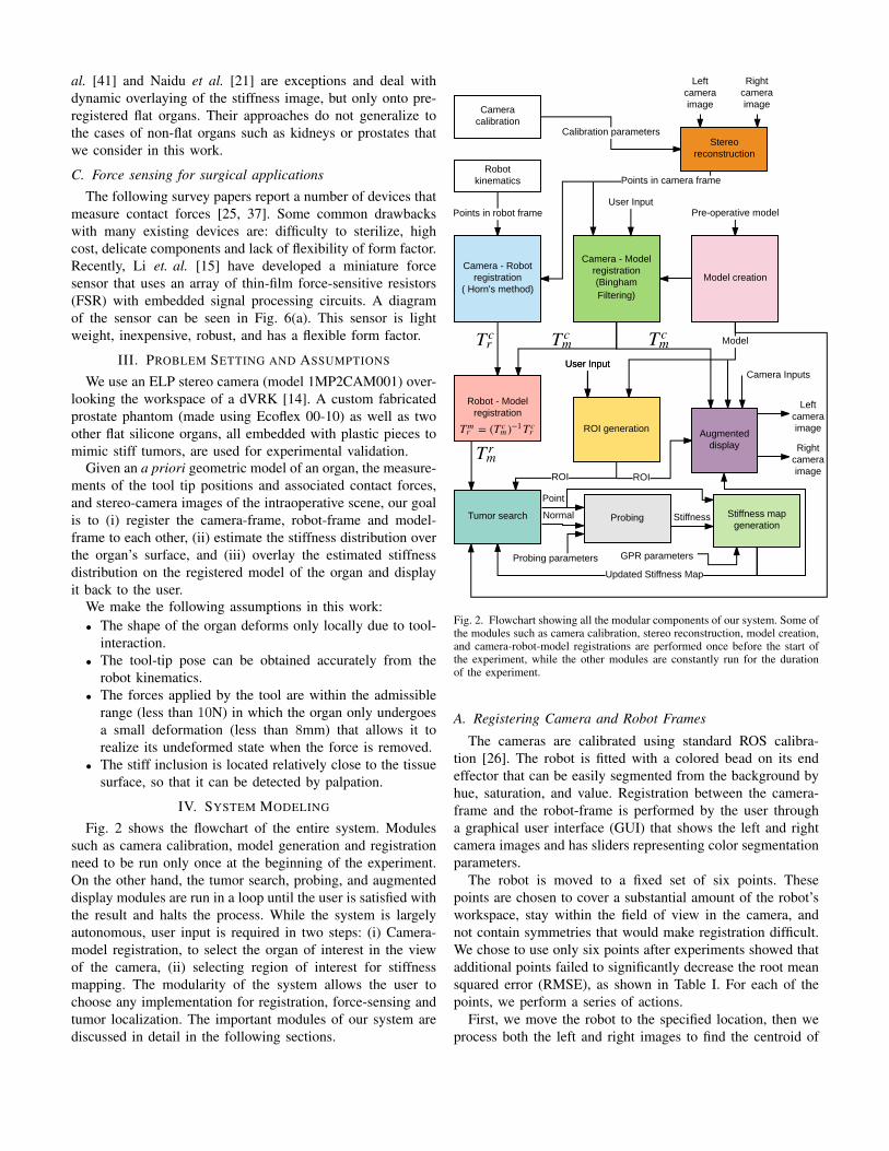
Fig. 2 shows the flowchart of the entire system. Modulessuch as camera calibration, model generation and registrationneed to be run only once at the beginning of the experiment.On the other hand, the tumor search, probing, and augmenteddisplay modules are run in a loop until the user is satisfied withthe result and halts the process. While the system is largelyautonomous, user input is required in two steps: (i) Camera-model registration, to select the organ of interest in the viewof the camera, (ii) selecting region of interest for stiffnessmapping. The modularity of the system allows the user tochoose any implementation for registration, force-sensing andtumor localization. The important modules of our system arediscussed in detail in the following sections.
Fig. 2. Flowchart showing all the modular components of our system. Some ofthe modules such as camera calibration, stereo reconstruction, model creation,and camera-robot-model registrations are performed once before the start ofthe experiment, while the other modules are constantly run for the durationof the experiment.
A. Registering Camera and Robot Frames
The cameras are calibrated using standard ROS calibra-tion [26]. The robot is fitted with a colored bead on its endeffector that can be easily segmented from the background byhue, saturation, and value. Registration between the camera-frame and the robot-frame is performed by the user througha graphical user interface (GUI) that shows the left and rightcamera images and has sliders representing color segmentationparameters.
The robot is moved to a fixed set of six points. Thesepoints are chosen to cover a substantial amount of the robot’sworkspace, stay within the field of view in the camera, andnot contain symmetries that would make registration difficult.We chose to use only six points after experiments showed thatadditional points failed to significantly decrease the root meansquared error (RMSE), as shown in Table I. For each of thepoints, we perform a series of actions.
First, we move the robot to the specified location, then weprocess both the left and right images to find the centroid of

TABLE I
Number of points 5 6 7 8 11 51
RMSE (mm) 2.71 2.37 2.84 3.01 2.82 2.85
the colored bead fitted to the robot. The centroid of the ball inpixels is found as the center of the minimum enclosing circleof the contour with the largest area. We repeat this for asmany frames as are received over ROS in one second (in ourcase 15), and the centroid is then averaged over all frames toreduce the effect of noise in the image. The centroid is drawnonto both images in the GUI, allowing the user to evaluatethe accuracy of the centroid estimation. The pixel disparity iscalculated as the difference between the x coordinates of thecentroid in the left and right images. This disparity is fed intoa stereo-camera model that ROS provides, to calculate a 3Dpoint in the camera-frame.
Following this, we obtain six points in both the camera-frame and the robot-frame (using the kinematics of the robot).We use Horn’s method [12] to calculate the transformation T c
m
between the camera and the robot frames. This transformationis saved to a file and the calculated RMSE is displayed to theuser. In addition, the robot’s current position is transformedby the inverse of the calculated transformation and projectedback into the pixel space of both cameras. Circles are drawnat these pixel positions in the left and right images in the GUIso that the user can visually confirm that the registration issuccessful and accurate.
B. Registering Camera and Preoperative Model Frames
The transformation between camera-frame and model-frame, T c
m is estimated by registering the reconstructed pointcloud from stereo images with the preoperative model ofthe organ. The intraoperative scene as viewed by the stereocameras is as shown in the top of Fig. 3. A user manuallyselects the region containing the organ of interest. Followingthis the user can also further refine the selection using a graphcut-based image segmentation.
A Bingham distribution-based filtering approach is used toautomatically register the stereo point cloud to the preoperativemodel [33, 34]. The mean time taken to register is 2s and theRMS error is 1.5mm. The center row in Fig. 3 shows theregistered model of the organ overlaid on the stereo views.Note how the pose of the registered model accurately matchesthe pose of the organ. In the same figure we also show themodel of the tumor in the registered view to highlight howaccurately the stiffness map estimates the location of the tumor(see bottom row of Fig. 3)
We also augmented the static grab-cut based segmentationusing an automatic traveling mask. Once we are satisfied thatthe model is roughly registered to the object, we switch fromthe static graph-cut mask to the traveling mask. Using thesame rendering engine used in the GUI, a z-depth buffer isrendered from the camera’s view of the model. This depthbuffer is scaled from 0 to 255 with 0 representing the pixel
Fig. 3. Top row: Original left and right camera images. Middle row:Camera images with registered prostate model shown in semi-transparentblue. The tumor model is also shown to allow us to compare our stiffnessmapping result. Bottom row: The robot probes the organ and records force-displacement measurements. The estimated stiffness map is then augmentedon the registered model in this figure. Dark blue regions show high stiffness.Note that the stiffness map reveals the location and shape of the tumor.
farthest from the camera and 255 representing the closest.Using this buffer, we create a new mask for our camera imageby masking out all pixels with a depth of zero, effectivelycreating a cutout of our rendered model. Because we render thedepth buffer every time the model’s estimated transformationis changed, we create an image mask that moves along withour model. Results using this traveling mask can be seenin Fig. 4. Tracking is maintained even after an disturbancemoves the silicone prostate out from under the tracked modelby approximately 4cm. Although extreme movements willcertainly make our system lose tracking, the system is robust tosmall movements that may arise due to breathing, heart beat aswell as due to interactive forces during palpation. To the bestof our knowledge the prior works on probing-based stiffnessmapping assume the organ is rigidly clamped with respect tothe robot and ignore movement of the organ [7, 21, 31, 41].
C. Tumor Search and Stiffness Mapping
The problem of tumor search is often posed as a problemof stiffness mapping, where the stiffness of each point on acertain organ is estimated, and regions with stiffness higherthan a certain threshold are considered as regions of interest(tumors, arteries, etc.). The framework that we use for local-izing tumors utilizes Gaussian processes (GP) to model the

12 14 16 18 20 22Time (seconds)
0.5
1
1.5
2
2.5
3
RM
S Er
ror (
met
ers)
10 -3
RMSTime (a)Time (b)Time (c)
Time (a)RMS: 0.00086435
Time (b)RMS: 0.0021977
Time (c)RMS: 0.00087708
Fig. 4. Registration results on a moving phantom prostate shown at three different times. Note the large disturbance at time (b) caused by applying an externalforce to the organ and the recovered tracking at time (c).
stiffness distribution combined with a GP-based acquisitionfunction to direct where to sample next for efficient and fasttumor localization. This is described in Fig. 5.
By using GP, we assume a smooth change in the stiffnessdistribution across the organ. Since every point on the organ’ssurface can be uniquely mapped to a 2D grid, the domainof search used is X ⊂ IR2. The measured force and positionafter probing the organ by the robot at x provides the stiffnessestimation represented by y.
The problem of finding the location and shape of thestiff inclusions can be modeled as an optimization problem.However, an exact functional form for such an optimizationis not available in reality. Hence, we maintain a probabilisticbelief about the stiffness distribution and define a so called“acquisition function”, ξacq , to determine where to samplenext. This acquisition function can be specified in various waysand thus our framework is flexible in terms of the choice ofthis acquisition function that is being optimized. Prior workshave considered various choices for the acquisition functionssuch as expectation improvement (EI) [1, 2], upper confidencebound (UCB) [8], uncertainty sampling (UNC), active area
search (AAS) and active level set estimation (LSE) [28].While our system is flexible to the choice of acquisition
function, in this work we demonstrate tumor localization usingLSE. LSE determines the set of points, for which an unknownfunction (stiffness map in our case) takes value above or belowsome given threshold level h. The mean and covariance of theGP can be used to define a confidence interval,
Qt(x) =[µt(x)± β1/2σt(x)
](1)
for each point x ∈ X . Furthermore, a confidence region Ct
which results from intersecting successive confidence intervalscan be defined as,
Ct(x) =
t⋂i=1
Qi(x). (2)
LSE then defines a measure of classification ambiguity at(x)defined as,
at(x) = min {max(Ct(x))− h, h−min(Ct(x))} . (3)
LSE chooses sequentially queries (probes) at x∗ such that,
x∗ = argmaxx∈X
at(x). (4)
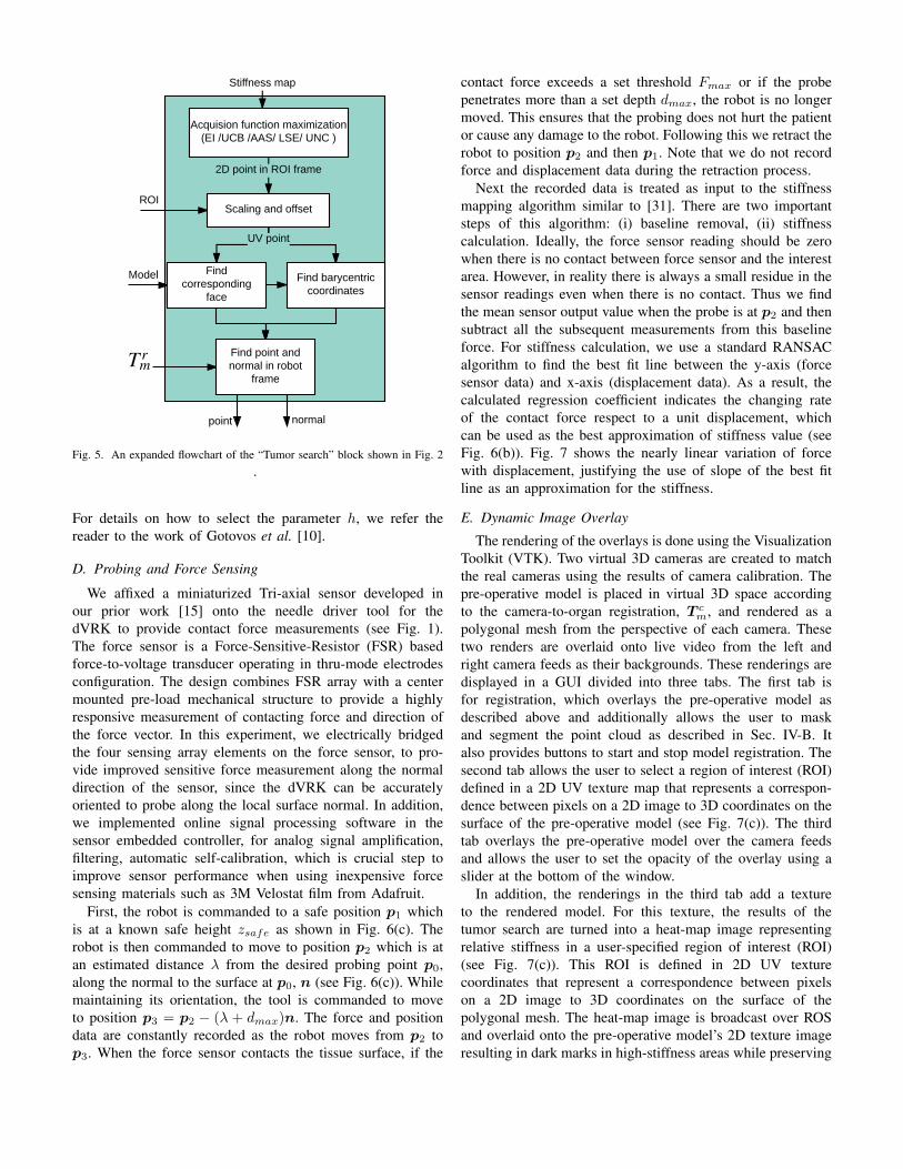
Fig. 5. An expanded flowchart of the “Tumor search” block shown in Fig. 2.
For details on how to select the parameter h, we refer thereader to the work of Gotovos et al. [10].
D. Probing and Force Sensing
We affixed a miniaturized Tri-axial sensor developed inour prior work [15] onto the needle driver tool for thedVRK to provide contact force measurements (see Fig. 1).The force sensor is a Force-Sensitive-Resistor (FSR) basedforce-to-voltage transducer operating in thru-mode electrodesconfiguration. The design combines FSR array with a centermounted pre-load mechanical structure to provide a highlyresponsive measurement of contacting force and direction ofthe force vector. In this experiment, we electrically bridgedthe four sensing array elements on the force sensor, to pro-vide improved sensitive force measurement along the normaldirection of the sensor, since the dVRK can be accuratelyoriented to probe along the local surface normal. In addition,we implemented online signal processing software in thesensor embedded controller, for analog signal amplification,filtering, automatic self-calibration, which is crucial step toimprove sensor performance when using inexpensive forcesensing materials such as 3M Velostat film from Adafruit.
First, the robot is commanded to a safe position p1 whichis at a known safe height zsafe as shown in Fig. 6(c). Therobot is then commanded to move to position p2 which is atan estimated distance λ from the desired probing point p0,along the normal to the surface at p0, n (see Fig. 6(c)). Whilemaintaining its orientation, the tool is commanded to moveto position p3 = p2 − (λ + dmax)n. The force and positiondata are constantly recorded as the robot moves from p2 top3. When the force sensor contacts the tissue surface, if the
contact force exceeds a set threshold Fmax or if the probepenetrates more than a set depth dmax, the robot is no longermoved. This ensures that the probing does not hurt the patientor cause any damage to the robot. Following this we retract therobot to position p2 and then p1. Note that we do not recordforce and displacement data during the retraction process.
Next the recorded data is treated as input to the stiffnessmapping algorithm similar to [31]. There are two importantsteps of this algorithm: (i) baseline removal, (ii) stiffnesscalculation. Ideally, the force sensor reading should be zerowhen there is no contact between force sensor and the interestarea. However, in reality there is always a small residue in thesensor readings even when there is no contact. Thus we findthe mean sensor output value when the probe is at p2 and thensubtract all the subsequent measurements from this baselineforce. For stiffness calculation, we use a standard RANSACalgorithm to find the best fit line between the y-axis (forcesensor data) and x-axis (displacement data). As a result, thecalculated regression coefficient indicates the changing rateof the contact force respect to a unit displacement, whichcan be used as the best approximation of stiffness value (seeFig. 6(b)). Fig. 7 shows the nearly linear variation of forcewith displacement, justifying the use of slope of the best fitline as an approximation for the stiffness.
E. Dynamic Image Overlay
The rendering of the overlays is done using the VisualizationToolkit (VTK). Two virtual 3D cameras are created to matchthe real cameras using the results of camera calibration. Thepre-operative model is placed in virtual 3D space accordingto the camera-to-organ registration, T c
m, and rendered as apolygonal mesh from the perspective of each camera. Thesetwo renders are overlaid onto live video from the left andright camera feeds as their backgrounds. These renderings aredisplayed in a GUI divided into three tabs. The first tab isfor registration, which overlays the pre-operative model asdescribed above and additionally allows the user to maskand segment the point cloud as described in Sec. IV-B. Italso provides buttons to start and stop model registration. Thesecond tab allows the user to select a region of interest (ROI)defined in a 2D UV texture map that represents a correspon-dence between pixels on a 2D image to 3D coordinates on thesurface of the pre-operative model (see Fig. 7(c)). The thirdtab overlays the pre-operative model over the camera feedsand allows the user to set the opacity of the overlay using aslider at the bottom of the window.
In addition, the renderings in the third tab add a textureto the rendered model. For this texture, the results of thetumor search are turned into a heat-map image representingrelative stiffness in a user-specified region of interest (ROI)(see Fig. 7(c)). This ROI is defined in 2D UV texturecoordinates that represent a correspondence between pixelson a 2D image to 3D coordinates on the surface of thepolygonal mesh. The heat-map image is broadcast over ROSand overlaid onto the pre-operative model’s 2D texture imageresulting in dark marks in high-stiffness areas while preserving

(a) (b)
Protective tip
Sensor Cable
Force Sensor
Tool/Sensor Adapter
Needle Driver Tool
(c)
Fig. 6. (a) The FSR sensor that we use in this paper, was developed by Li et al. [15]. (b) An expanded flowchart of the “Probing” block shown in Fig. 2.(c) The various steps taken to probe a desired point along a desired normal direction as provided by the tumor search module.
A
B
Fig. 7. Force magnitude vs displacement for two sample points A and B onthe surface of the organ. RANSAC is used to find the best-fit line and theslope gives us an estimate of the stiffness at the probed location. The circular2D space forms a one-to-one mapping with the 3D surface of the organ. Thegreen circle represents the user-defined ROI where stiffness map is estimated.Point A is located in on a stiff region, while B is located on a soft region.
texture details found in the pre-operative model’s originaltexture (see Fig. 7(c)). This 2D texture is then applied to thepolygonal mesh using the UV map, resulting in a 3D overlayof the stiffness map onto the video feed from each camera.Fig. 8 shows the stiffness maps at various stages of probing,dynamically overlaid on the registered model of the organ.Note that the stiffness map clearly reveals the location andshape of the tumor which is shown in the middle row of Fig. 3.
V. EXPERIMENTS AND VALIDATION
In this section, we validate our system through experimenta-tion on various phantom models. In addition to the experimentsperformed on the silicone prostate phantom, an experiment
(a) (b) (c)
Fig. 8. The figures show the augmented stiffness map at various stagesof probing. The high stiffness regions are shown in darker shades of blue,while the low stiffness regions are in lighter shades of blue.(a) Result after 4probings, (b) result after 18 probings, (c) result after 36 probings.
was performed on a custom fabricated flat silicone organembedded with plastic inclusions to mimic stiff tumors. Weused the dVRK robot with the organ placed on a force sensingplate fitted with a commercial force sensor created by ATI togenerate the ground truth stiffness maps.
Upon generating the ground truth stiffness maps using araster scan pattern with a high density of probed points,the silicone organs were registered and probed using theregistration and search methods described in Sec IV. It is worthnoting, that unlike Yamamoto et. al. [41], we do not assumethe flat organ is pre-registered. We estimate the registrationfrom the stereo-camera and use the estimated registration forthe overlay. Also the force sensing plate is only for groundtruth stiffness mapping. For the actual experiments, we usethe miniature force sensor shown in Fig. 6(a). The resultingstiffness maps, as well as a comparison of how the mapsappear when overlaid in our GUI, can be seen in Fig. 9 and10. These figures show that our system is able to capture theposition and size of the tumors with far fewer probed pointsin a fraction of the time taken to generate the dense stiffnessmap1. Fig. 10(e) and (f) show the front and back view ofthe phantom prostate with the overlaid image of the estimated
1The experiments with our system took a total of 3 minutes to execute asopposed to the raster scan that took upwards of 90 minutes.

Fig. 9. Experiments on the flat silicone organ. (a) The ground truth stiffnessmap. (b) The stiffness map as estimated by our system. The probed locationsare shown by blue dots. (c) The ground truth stiffness map overlaid on topof the phantom organ. (d) The estimated stiffness map overlaid on top of thephantom organ. The stiffness maps are shown in the space of the UV map.The x and y range for ground truth and estimated stiffness maps are the same.
TABLE IIACCURACY, RECALL AND PRECISION OF ESTIMATED STIFFNESS MAPS
Accuracy (%) Recall (%) Precision (%)Prostate 98.08 82.04 85.77Flat organ 88.50 92.11 72.21
stiffness along with the surface normals at the locations theorgan was probed. As is evidenced by this figure, our systemis capable of probing and overlaying the image on a non-flathighly curved organ.
Table II shows the precision, accuracy and recall of theestimated stiffness maps when compared to the ground truth.Precision, accuracy and recall are popular metrics to compareperformance of regions-of-interest detection problems andhave been used to compare stiffness maps in literature [28].The results show that the shape and location of tumor asestimated by our approach is accurate and closely matches theground truth. Although the exact shape of the tumors is notperfectly captured for the case of the flat organ, the resultingmap is more than enough to show the user where the tumorsare located. The RMS error in the stiffness estimation for theprostate phantom is 18.71 N/m and for the flat organ is 40.09N/m, which is sufficient for a surgeon to differentiate tumorfrom tissue as noted by Chalasani et. al. [5, 7].
VI. DISCUSSIONS AND FUTURE WORK
In this paper, we presented a system that unifies autonomoustumor search with augmented reality to quickly reveal theshape and location of the tumors while visually overlayingthat information on the real organ. Our system is capable ofprobing highly curved organs as well as tracking the movementof the organ that may be caused by the forceful interaction.This has the potential to reduce the cognitive overload of
Fig. 10. Experiments on the phantom prostate. (a) The ground truth stiffnessmap. (b) The stiffness map as estimated by our system. The probed locationsare shown by blue dots. (c) The ground truth stiffness map overlaid on topof the phantom organ. The stiffness maps are shown in the space of the UVmap. The x and y range for ground truth and estimated stiffness maps are thesame. (d) The estimated stiffness map overlaid on top of the phantom organ.(e) and (f) show the front and back view respectively, of the prostate modelwith an overlay of the estimated stiffness map. The surface normals at thevarious probed locations are shown by the green arrows.
the surgeons and assist them during the surgery. Our systemdemonstrates promising results in experimentation on phantomsilicone organs.
While we demonstrate the task of stiffness mapping in thiswork, our system can be used to visually overlay pre-surgicalplans, ablation paths, annotate important landmarks, etc. to aidthe surgeon during the procedure. In our future work we planto account for large deformations of the organ and updatethe model accordingly. We plan to utilize computationallyfast approaches to segment the dVRK tools from the imagesand avoid any obstructions to the overlaid stiffness map.Furthermore, as demonstrated by other researchers in this field,we believe a hybrid force-position controller can result in moreaccurate probing and hence better stiffness estimation. Finally,we plan to perform experiments on ex-vivo organs and carryuser studies to asses the efficacy of the system in a realisticsurgical setting.
ACKNOWLEDGMENTS
This work has been funded through the National RoboticsInitiative by NSF grant IIS-1426655 and the Center for Ma-chine Learning and Health.

REFERENCES
[1] Elif Ayvali, Rangaprasad Arun Srivatsan, Long Wang,Rajarshi Roy, Nabil Simaan, and Howie Choset. UsingBayesian Optimization to Guide Probing of a FlexibleEnvironment for Simultaneous Registration and StiffnessMapping. In Proceedings of the International Con-ference on Robotics and Automation (ICRA), number10.1109/ICRA.2016.7487225, pages 931–936, 2016.
[2] Elif Ayvali, Alexander Ansari, Long Wang, NabilSimaan, and Howie Choset. Utility-Guided Palpationfor Locating Tissue Abnormalities. IEEE Robotics andAutomation Letters, 2(2):864–871, 2017.
[3] Paul J Besl and Neil D McKay. Method for registrationof 3-D shapes. In Robotics-DL tentative, pages 586–606.International Society for Optics and Photonics, 1992.
[4] Seth D Billings, Emad M Boctor, and Russell H Taylor.Iterative most-likely point registration (IMLP): A robustalgorithm for computing optimal shape alignment. PloSone, 10(3):e0117688, 2015.
[5] Preetham Chalasani, Long Wang, Rajarshi Roy, NabilSimaan, Russell H Taylor, and Marin Kobilarov. Con-current nonparametric estimation of organ geometry andtissue stiffness using continuous adaptive palpation. InICRA, pages 4164–4171. IEEE, 2016.
[6] Preetham Chalasani, Anton Deguet, Peter Kazanzides,and Russell H Taylor. A Computational Framework forComplementary Situational Awareness (CSA) in SurgicalAssistant Robots. In 2018 Second IEEE InternationalConference on Robotic Computing (IRC), pages 9–16.IEEE, 2018.
[7] Preetham Chalasani, Long Wang, Rashid Yasin, NabilSimaan, and Russell H Taylor. Preliminary Evaluation ofan Online Estimation Method for Organ Geometry andTissue Stiffness. IEEE Robotics and Automation Letters,3(3):1816–1823, 2018.
[8] Animesh Garg, Siddarth Sen, Rishi Kapadia, YimingJen, Stephen McKinley, Lauren Miller, and Ken Gold-berg. Tumor localization using automated palpationwith gaussian process adaptive sampling. In proceedingsof International Conference on Automation Science andEngineering (CASE), pages 194–200. IEEE, 2016.
[9] Roger E Goldman, Andrea Bajo, and Nabil Simaan.Algorithms for autonomous exploration and estimation incompliant environments. Robotica, 31(1):71–87, 2013.
[10] Alkis Gotovos, Nathalie Casati, Gregory Hitz, and An-dreas Krause. Active learning for level set estimation. InIJCAI, pages 1344–1350, 2013.
[11] Nazim Haouchine, Jeremie Dequidt, Igor Peterlik, ErwanKerrien, Marie-Odile Berger, and Stephane Cotin. To-wards an accurate tracking of liver tumors for augmentedreality in robotic assisted surgery. In ICRA, pages 4121–4126, 2014.
[12] Berthold KP Horn. Closed-form solution of absoluteorientation using unit quaternions. JOSA A, 4(4):629–642, 1987.
[13] Robert D Howe, William J Peine, DA Kantarinis, andJae S Son. Remote palpation technology. IEEE Engi-neering in Medicine and Biology Magazine, 14(3):318–323, 1995.
[14] Peter Kazanzides, Zihan Chen, Anton Deguet, Gregory SFischer, Russell H Taylor, and Simon P DiMaio. Anopen-source research kit for the da Vinci® SurgicalSystem. In ICRA, pages 6434–6439. IEEE, 2014.
[15] Lu Li, Bocheng Yu, Chen Yang, Prasad Vagdargi, Ran-gaprasad Arun Srivatsan, and Howie Choset. Devel-opment of an Inexpensive Tri-axial Force Sensor forMinimally Invasive Surgery. In In proceedings of theInternational Conference on Intelligent Robots and Sys-tems (IROS). IEEE, 2017.
[16] Hongbin Liu, David P Noonan, Benjamin J Challacombe,Prokar Dasgupta, Lakmal D Seneviratne, and KasparAlthoefer. Rolling mechanical imaging for tissue ab-normality localization during minimally invasive surgery.IEEE Transactions on Biomedical Engineering, 57:404–414, 2010.
[17] Jacques Marescaux, Francesco Rubino, Mara Arenas, Di-dier Mutter, and Luc Soler. Augmented-reality–assistedlaparoscopic adrenalectomy. Jama, 292(18):2211–2215,2004.
[18] Stephen McKinley, Animesh Garg, Siddarth Sen, RishiKapadia, Adithyavairavan Murali, Kirk Nichols, SusanLim, Sachin Patil, Pieter Abbeel, Allison M Okamura,et al. A single-use haptic palpation probe for locatingsubcutaneous blood vessels in robot-assisted minimallyinvasive surgery. In proceedings of International Con-ference on Automation Science and Engineering (CASE),pages 1151–1158. IEEE, 2015.
[19] Mehdi Hedjazi Moghari and Purang Abolmaesumi.Point-based rigid-body registration using an unscentedKalman filter. IEEE Transactions on Medical Imaging,26(12):1708–1728, 2007.
[20] A. Myronenko and Xubo Song. Point Set Registration:Coherent Point Drift. IEEE Transactions on PatternAnalysis and Machine Intelligence, 32(12):2262–2275,Dec 2010. ISSN 0162-8828. doi: 10.1109/TPAMI.2010.46.
[21] Anish S Naidu, Michael D Naish, and Rajni V Patel. ABreakthrough in Tumor Localization. IEEE Robotics &Automation Magazine, 1070(9932/17), 2017.
[22] Kirk A Nichols and Allison M Okamura. Methods tosegment hard inclusions in soft tissue during autonomousrobotic palpation. IEEE Transactions on Robotics, 31(2):344–354, 2015.
[23] Jaydeep Palep. Robotic assisted minimally invasivesurgery. Journal of Minimal Access Surgery, 5(1):1–7,Jan 2009.
[24] Kartik Patath, Rangaprasad Arun Srivatsan, Nicolas Ze-vallos, and Howie Choset. Dynamic Texture Mapping of3D models for Stiffness Map Visualization. In Workshopon Medical Imaging, IEEE/RSJ International Conferenceon Intelligent Robots and Systems (IROS), 2017.
[25] Pinyo Puangmali, Kaspar Althoefer, Lakmal D Senevi-ratne, Declan Murphy, and Prokar Dasgupta. State-of-the-art in force and tactile sensing for minimally invasivesurgery. IEEE Sensors Journal, 8(4):371–381, 2008.
[26] Morgan Quigley, Ken Conley, Brian Gerkey, Josh Faust,Tully Foote, Jeremy Leibs, Rob Wheeler, and Andrew YNg. ROS: an open-source Robot Operating System.In ICRA workshop on open source software, volume 3,page 5. Kobe, Japan, 2009.
[27] Szymon Rusinkiewicz and Marc Levoy. Efficient variantsof the ICP algorithm. In Proceedings of 3rd InternationalConference on 3-D Digital Imaging and Modeling, pages145–152. IEEE, 2001.
[28] Hadi Salman, Elif Ayvali, Rangaprasad Arun Srivatsan,Yifei Ma, Nicolas Zevallos, Rashid Yasin, Long Wang,Nabil Simaan, and Howie Choset. Trajectory-OptimizedSensing for Active Search of Tissue Abnormalities inRobotic Surgery. In proceedings of International Con-ference on Robotics and Automation (ICRA). IEEE, 2018.
[29] Siddharth Sanan, Stephen Tully, Andrea Bajo, NabilSimaan, and Howie Choset. Simultaneous Complianceand Registration Estimation for Robotic Surgery. InProceedings of the Robotics: Science and Systems Con-ference, 2014.
[30] Jeffrey H Shuhaiber. Augmented reality in surgery.Archives of surgery, 139(2):170–174, 2004.
[31] Rangaprasad Arun Srivatsan, Elif Ayvali, Long Wang,Rajarshi Roy, Nabil Simaan, and Howie Choset. Com-plementary Model Update: A Method for SimultaneousRegistration and Stiffness Mapping in Flexible Environ-ments. In Proceedings of the International Conference onRobotics and Automation (ICRA), pages 924–930, 2016.
[32] Rangaprasad Arun Srivatsan, Gillian T Rosen, Feroze DNaina, and Howie Choset. Estimating SE(3) elementsusing a dual quaternion based linear Kalman filter. InRobotics : Science and Systems, 2016.
[33] Rangaprasad Arun Srivatsan, Mengyun Xu, Nicolas Ze-vallos, and Howie Choset. Bingham Distribution-BasedLinear Filter for Online Pose Estimation. In Robotics :Science and Systems (RSS), 2017.
[34] Rangaprasad Arun Srivatsan, Mengyun Xu, Nicolas Ze-vallos, and Howie Choset. Probabilistic pose estimationusing a bingham distribution- based linear filter. TheInternational Journal of Robotics Research (IJRR), 2018.
[35] Li-Ming Su, Balazs P Vagvolgyi, Rahul Agarwal, Carol EReiley, Russell H Taylor, and Gregory D Hager. Aug-mented reality during robot-assisted laparoscopic partialnephrectomy: toward real-time 3D-CT to stereoscopicvideo registration. Urology, 73(4):896–900, 2009.
[36] Dogu Teber, Selcuk Guven, Tobias Simpfendorfer, Math-ias Baumhauer, Esref Oguz Guven, Faruk Yencilek,Ali Serdar Gozen, and Jens Rassweiler. Augmentedreality: a new tool to improve surgical accuracy duringlaparoscopic partial nephrectomy? Preliminary in vitroand in vivo results. European urology, 56(2):332–338,2009.
[37] Mohsin I Tiwana, Stephen J Redmond, and Nigel HLovell. A review of tactile sensing technologies withapplications in biomedical engineering. Sensors andActuators A: physical, 179:17–31, 2012.
[38] Ana Luisa Trejos, Jagadeesan Jayender, MT Perri,Michael D Naish, Rajnikant V Patel, and RA Malthaner.Robot-assisted tactile sensing for minimally invasivetumor localization. The International Journal of RoboticsResearch (IJRR), 28(9):1118–1133, 2009.
[39] Long Wang, Zihan Chen, Preetham Chalasani, Jason Pile,Peter Kazanzides, Russell H Taylor, and Nabil Simaan.Updating virtual fixtures from exploration data in force-controlled model-based telemanipulation. In ASME 2016International Design Engineering Technical Conferencesand Computers and Information in Engineering Confer-ence, pages V05AT07A031–V05AT07A031. AmericanSociety of Mechanical Engineers, 2016.
[40] Long Wang, Zihan Chen, Preetham Chalasani, Rashid MYasin, Peter Kazanzides, Russell H Taylor, and NabilSimaan. Force-Controlled Exploration for UpdatingVirtual Fixture Geometry in Model-Mediated Telema-nipulation. Journal of Mechanisms and Robotics, 9(2):021010, 2017.
[41] Tomonori Yamamoto, Balazs Vagvolgyi, Kamini Balaji,Louis L Whitcomb, and Allison M Okamura. Tissueproperty estimation and graphical display for teleoper-ated robot-assisted surgery. In ICRA, pages 4239–4245,2009.
[42] Nicolas Zevallos, Rangaprasad Arun Srivatsan, HadiSalman, Lu Li, Jianing Qian, Saumya Saxena, MengyunXu, Kartik Patath, and Howie Choset. A surgical systemfor automatic registration, stiffness mapping and dynamicimage overlay. In International Symposium on MedicalRobotics (ISMR), pages 1–6. IEEE, 2018.