A Rapid Penetration Trajectory Optimization Method...
12
Research Article A Rapid Penetration Trajectory Optimization Method for Hypersonic Vehicles Binbin Yan, Ruifan Liu , Pei Dai, Muzeng Xing, and Shuangxi Liu School of Astronautics, Northwestern Polytechnical University, Xi’an 710072, China Correspondence should be addressed to Ruifan Liu; [email protected] Received 8 January 2019; Revised 13 April 2019; Accepted 13 June 2019; Published 9 July 2019 Academic Editor: Maj D. Mirmirani Copyright © 2019 Binbin Yan et al. This is an open access article distributed under the Creative Commons Attribution License, which permits unrestricted use, distribution, and reproduction in any medium, provided the original work is properly cited. The evasion maneuver problem of hypersonic vehicles differs from those of ballistic missiles and other traditional weapons, showing distinctive properties including expansive maneuver range and weak maneuverability. How to avoid the disadvantage of low available overload and ensure follow-up tasks are the main concerns of the hypersonic penetration. This paper presents a penetration trajectory optimization algorithm for an air-breathing hypersonic vehicle, where the prerequisite penetration condition is analyzed and control costs are chosen as an objective function to minimize the fuel consumption and maneuver range. This paper focuses on how to formulate the complex, highly constrained nonconvex penetration problem to be a sequence of easily solved second-order cone programming through a combination of successive linearization and relaxation techniques. Innovation lies in the raising of the penetration angle and the relaxation technique of nonlinear and nonconvex elements. Various numerical simulations are conducted to verify the validity of penetration condition and to demonstrate that the proposed method is effective and has a good computational performance irrespective of initial guesses. 1. Introduction Since the hypersonic vehicles have arrived, the attack and defense countermeasure game centered on it receives the focal attention by various military powers. The air-breathing hyper- sonic vehicle cruises at the altitude of the near space, featuring a lasting and wide-range maneuverability. But owing to the usage of the unique integrated propulsion technology and the scramjet engine [1], strict constraints are also imposed on its maneuverability, including the attack angle and bank angle [2, 3]. Therefore, the hypersonic penetration possesses characteristics of a “wide maneuvering range, weak maneu- verability, and high flight speed.” Besides, the prominent infrared features of hypersonic vehicles make it easily to be detected and intercepted. Consequently, how to make maxi- mal use of the speed superiority and achieve penetration with minimal energy consumption are the core of hyper- sonic penetration programming. In the confrontation, the hypersonic vehicle and the interception missile maneuver actively and simultaneously, thus always regarded as a complicated gaming problem. With the game theory, differential gaming models are established. Shaferman and Shima [4, 5] studied the zero-sum differential game theory, the quadratic differential game theory, and var- ious other forms of differential game and analyzed the condi- tions in which the saddle points of the differential game exist. However, most of studies of differential game theory focus on mathematical modeling and theoretical derivation, while its application to practical engineering remains a challenge [6]. Considering the huge speed gap, the game problem between a hypersonic vehicle and an interception missile is not like the normal one. In other words, only when harsh intercep- tion conditions are satisfied can the interceptor succeed. Accordingly, Dwivedi et al. [7] presented a midcourse guid- ance law against high-speed targets believing that alignment angle constraints in both elevation and azimuth could create Hindawi International Journal of Aerospace Engineering Volume 2019, Article ID 1490342, 11 pages https://doi.org/10.1155/2019/1490342
Transcript of A Rapid Penetration Trajectory Optimization Method...

Research ArticleA Rapid Penetration Trajectory Optimization Method forHypersonic Vehicles
Binbin Yan, Ruifan Liu , Pei Dai, Muzeng Xing, and Shuangxi Liu
School of Astronautics, Northwestern Polytechnical University, Xi’an 710072, China
Correspondence should be addressed to Ruifan Liu; [email protected]
Received 8 January 2019; Revised 13 April 2019; Accepted 13 June 2019; Published 9 July 2019
Academic Editor: Maj D. Mirmirani
Copyright © 2019 Binbin Yan et al. This is an open access article distributed under the Creative Commons Attribution License,which permits unrestricted use, distribution, and reproduction in any medium, provided the original work is properly cited.
The evasion maneuver problem of hypersonic vehicles differs from those of ballistic missiles and other traditional weapons,showing distinctive properties including expansive maneuver range and weak maneuverability. How to avoid the disadvantageof low available overload and ensure follow-up tasks are the main concerns of the hypersonic penetration. This paper presents apenetration trajectory optimization algorithm for an air-breathing hypersonic vehicle, where the prerequisite penetrationcondition is analyzed and control costs are chosen as an objective function to minimize the fuel consumption and maneuverrange. This paper focuses on how to formulate the complex, highly constrained nonconvex penetration problem to be asequence of easily solved second-order cone programming through a combination of successive linearization and relaxationtechniques. Innovation lies in the raising of the penetration angle and the relaxation technique of nonlinear and nonconvexelements. Various numerical simulations are conducted to verify the validity of penetration condition and to demonstrate thatthe proposed method is effective and has a good computational performance irrespective of initial guesses.
1. Introduction
Since the hypersonic vehicles have arrived, the attack anddefense countermeasure game centered on it receives the focalattention by various military powers. The air-breathing hyper-sonic vehicle cruises at the altitude of the near space, featuringa lasting and wide-range maneuverability. But owing to theusage of the unique integrated propulsion technology andthe scramjet engine [1], strict constraints are also imposedon its maneuverability, including the attack angle and bankangle [2, 3]. Therefore, the hypersonic penetration possessescharacteristics of a “wide maneuvering range, weak maneu-verability, and high flight speed.” Besides, the prominentinfrared features of hypersonic vehicles make it easily to bedetected and intercepted. Consequently, how to make maxi-mal use of the speed superiority and achieve penetrationwith minimal energy consumption are the core of hyper-sonic penetration programming.
In the confrontation, the hypersonic vehicle and theinterception missile maneuver actively and simultaneously,thus always regarded as a complicated gaming problem.Withthe game theory, differential gaming models are established.Shaferman and Shima [4, 5] studied the zero-sum differentialgame theory, the quadratic differential game theory, and var-ious other forms of differential game and analyzed the condi-tions in which the saddle points of the differential game exist.However, most of studies of differential game theory focus onmathematical modeling and theoretical derivation, while itsapplication to practical engineering remains a challenge [6].Considering the huge speed gap, the game problem betweena hypersonic vehicle and an interception missile is not likethe normal one. In other words, only when harsh intercep-tion conditions are satisfied can the interceptor succeed.Accordingly, Dwivedi et al. [7] presented a midcourse guid-ance law against high-speed targets believing that alignmentangle constraints in both elevation and azimuth could create
HindawiInternational Journal of Aerospace EngineeringVolume 2019, Article ID 1490342, 11 pageshttps://doi.org/10.1155/2019/1490342

a favorable condition for the terminal guidance while Guoet al. [8] tried to guide a hypersonic vehicle to break thealignment angle of the interceptor from an opponent view;thus, they converted the penetration problem into an opti-mal control problem.
In fact, using optimal control techniques for guidance offlight vehicles is not new. Numerical methods, like the shoot-ing method [9], the gradient method [10], and the recentlyprominent one, the pseudospectral method [11, 12], havebeen developed to solve two-point boundary value prob-lems (TPBVPs) derived from optimal problems. However,all of them lead to large computations that are infeasibleto implement in real time. Other contributions have alsobeen proposed in this regard, such as the model predictivecontrol (MPC) theory [13] combined with approximatedynamic programming (APC) and model predictive staticprogramming (MPSP) [7, 8]. The former one has been suc-cessfully used in the industry (especially in slow-varyingprocess control) but is not guaranteed to remain optimaland stable for its sliding time window [13, 14]. As to MPSPwhich is rather efficient and adaptable, however, whenapplied to the hypersonic vehicle, it is also not a preferablemethod since it cannot properly solve the optimal problemswith control constraints.
This paper is aimed at designing a rapid penetrationmethod to generate an appropriate evasion trajectory ofa hypersonic vehicle against a head-on intercepting mis-sile. According to the above content, the main two barriersof this problem are an explicit expression of penetrationcondition and a rapid, robust optimization algorithm cater-ing both terminal angular constraints and the demandingcontrol constraints of hypersonic vehicles. About the for-mer, this paper introduces the concept of the penetrationangle on the basis of interception geometry, giving theclear formula of penetration condition. The validity ofthe condition is also verified by the numerical simulationin terms of the ultimate miss distance under different pen-etration angles. As to the feasible optimization method,this paper raises a method based on sequential convexprogramming, which could meet the control constraintsas well as the penetration angle constraints in a shorttime, and compared with the existing optimal methodGPM, the algorithm proposed in this paper has a verycompetitive convergence rate and does not require good ini-tial guesses.
Convex optimization has been widely utilized in recentyears for its unique theoretical advantages and the polyno-mial time complexity [15, 16]. However, applications ofconvex optimization in aerospace trajectory planning havebeen limited to problems without complex nonlineardynamics and aerodynamic forces so far. This paper ismainly devoted to this difficulty in the penetration applica-tion. The technique developed in this paper successfully“convexifies” the initial nonconvex penetration probleminto a series of second-order cone programming (SOCP)problems. Various convexity strategies are applied to differ-ent nonconvex elements. The SOCP-based method provesto be a very robust and rapid tool for hypersonic penetrationtrajectory optimization. Numerical results are provided to
demonstrate the effectiveness and some of the noteworthyaspects of the method.
The rest of this paper is organized as follows. In Section 2,the countermeasure model is established, including thehypersonic vehicle model, the interceptor model, and therelative motion model, and thus, the original form of pen-etration problem is described. In Section 3, the convexifica-tion process is explained in detail and the converted SOCPproblem is presented. Numerical simulation results are pre-sented in Section 4. Finally, some conclusions are drawn inSection 5.
2. Mathematical Model for Attack andDefense Countermeasure
The primary objective of this paper is to present an effectivepenetration guidance logic. Hence, considering solving speedand application feasibility, one only requires point massmathematical models for both the vehicle and the intercep-tion missile. Moreover, with the complex high-fidelity model,the calculation of Jacobi matrices presented in Section 3 willbe boosted. Therefore, it is crucial to formulate the penetra-tion problem in a certain simplified way conducive to theSOCP approach. This section presents the details of one suchformulation of the problem.
2.1. Dynamics of the Hypersonic Vehicle. The penetrationmaneuver of a hypersonic vehicle is a short-range trajectoryoptimization problem; for this reason, we simplify its kine-matic equation sets as follows:
(a) With the rotation of the Earth not taken into account,namely, ignoring the Coriolis acceleration and con-vective acceleration
(b) Assuming that the Earth is flat, namely, ignoring theinfluence of its centrifugal force
And as is mentioned above, this paper pays most of itsattention to the trajectory programming; therefore, the masspoint model is established and some simplifications of thevehicle’s thrust and aerodynamic forces are conducted.
Thus, we obtain the following equations of the mass pointmotion model of the hypersonic vehicle:
he =Ve sin θe,
Ve =T cos αT −D
m− g sin θe,
θe =T sin αT cos σ + LT cos σ
mVe−g cos θe
Ve,
ψe =T sin αT sin σ + LT sin σ
mVe cos θe,
me = −ms,
1
where he is the altitude of the hypersonic vehicle; Ve is thespeed; θe and ψe represent the flight path angle and trajectorydeflection angle; αT and σ are the angle of attack and bank
2 International Journal of Aerospace Engineering

angle; LT ,D, and T are its aerodynamic force and thrust; meis its mass; ms is its mass consumption rate.
The thrust model, the aerodynamic force model, and thecontrol constraints are as follows:
LT = 0 5ρV2eS CL0 + Cα
LαT ,
D = 0 5ρV2eS CD0 + Cα2
D α2T ,
T = 0 5ρV2eSC
msT ms,
αT min ≤ αT ≤ αT max,
σ ≤ σmax,
0 ≤ms ≤ms max,
2
where αT min and αT max represent the boundaries of attack ofthe angle while σmax and ms max represent the upper limits ofthe bank angle rate and mass consumption rate, respectively.
2.2. Dynamics of the Interception Missile. For the midcourseguidance of an interception missile against a high-speed tar-get, it is desirable to shape the missile trajectory that providesa preferable initial state for terminal attack. Instead of theguidance laws carried out according to the nonlinear theoryand the MPSP algorithm, whose practicability are alwaysrestricted in application, this paper utilizes a more compen-dious and feasible guidance law called the trajectory shapingguidance law [17, 18].
The trajectory shaping guidance law has been developedto travel to the desired trajectory and verified by physicalapplications, such as landing the Apollo spacecraft on themoon. The guidance law appears to be a form of aug-mented proportional navigation plus an extra term that is
proportional to the difference between the line of sightangle and the desired angle at the end of flight. The appli-cation formula for this paper is as follows:
θi =N1qy +N2 tgo qy + θe ,
ψi =N1qz +N3 tgo qz − ψe + π ,3
where θi and ψi are the flight path angle and the trajectorydeflection angle; qy and qz are the line of sight (LOS) anglein elevation and azimuth, respectively. Figure 1 showsexplicit geometric meaning; N1,N2,N3 are the constantsof the guidance law, where tgo is the remaining flight time.
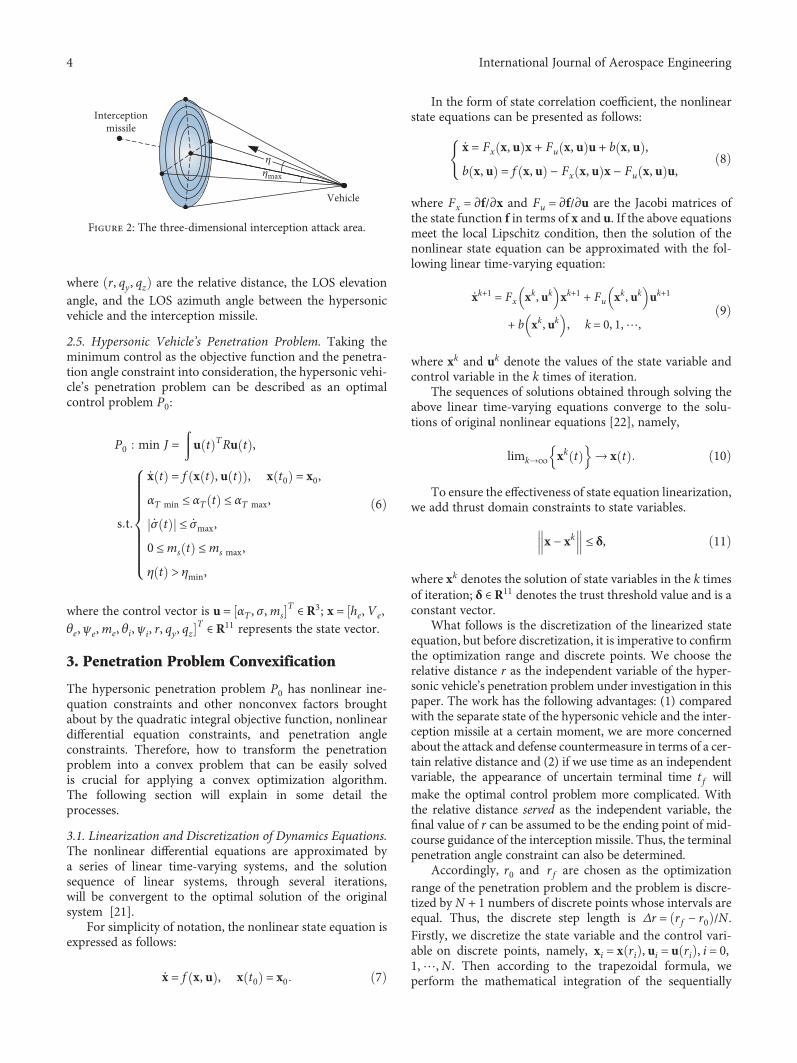
2.3. Attack and Defense Countermeasure Analysis. Underusual circumstances, the speed of a hypersonic vehicle ismuch higher than that of a defense system. Hence, only thehead-on strike by an interception missile can impose a threatto the hypersonic vehicle. Through reasonable assumptionsand simplifications, the interception geometry is established,and thus, one can gain the interception missile’s attack area.The attack area is a round spherical surface that includes theinterception missile but excludes the hypersonic vehicle, andits boundary is tangent to the hypersonic vehicle, as shown inFigure 2. See reference [19] for specific derivation processes.
It is known from interception geometry that if the veloc-ity vector of the hypersonic vehicle is always outside of theinterception geometric tangent line, namely, η > ηmax, thenit can break through the head-on strike situation of the inter-ception missile, achieving a successful penetration [20].
η is defined as the penetration angle of the hypersonicvehicle, namely, the angle between the line-of-sight and thevelocity of the hypersonic vehicle. Its cosine value can beobtained with the transformation matrices of the ground-trajectory coordinate system and the ground-LOS coordinatesystem. The relationship can be formulated as follows:
cos η = − cos qy cos θe cos qz − ψe − sin θe sin qy 4
2.4. Mathematical Model of Relative Motions. With the pen-etration angle constraints taken into consideration, themodel of relative motion between the hypersonic vehicleand the interception missile is established under the LOScoordinate system. The spatial coordinates and relative kinet-ics in the attack and defense countermeasure are shown inFigure 1.
The relative motions are defined by the followingequations:
z
x
y
Interceptionmissile
Vehicle
e
θe ψe
ψi
qyqz
θi
Figure 1: Relative kinetics in the attack and defense countermeasure.
r = Ve cos θe cos qy cos ψe − qz + sin θe sin qy − Vi cos θi cos qy cos ψi − qz + sin θi sin qy ,
qyr = −Ve cos θe sin qy cos ψe − qz − sin θe cos qy + Vi cos θi sin qy cos ψi − qz − sin θi cos qy ,
qzr cos qy = Ve cos θe sin ψe − qz − Vi cos θi sin ψi − qz ,
5
3International Journal of Aerospace Engineering
where r, qy , qz are the relative distance, the LOS elevationangle, and the LOS azimuth angle between the hypersonicvehicle and the interception missile.
2.5. Hypersonic Vehicle’s Penetration Problem. Taking theminimum control as the objective function and the penetra-tion angle constraint into consideration, the hypersonic vehi-cle’s penetration problem can be described as an optimalcontrol problem P0:
P0 min J = u t TRu t ,
s t
x t = f x t , u t , x t0 = x0,αT min ≤ αT t ≤ αT max,
σ t ≤ σmax,
0 ≤ms t ≤ms max,
η t > ηmin,
6
where the control vector is u = αT , σ,msT ∈ R3; x = he, Ve,
θe, ψe,me, θi, ψi, r, qy, qzT ∈ R11 represents the state vector.
3. Penetration Problem Convexification
The hypersonic penetration problem P0 has nonlinear ine-quation constraints and other nonconvex factors broughtabout by the quadratic integral objective function, nonlineardifferential equation constraints, and penetration angleconstraints. Therefore, how to transform the penetrationproblem into a convex problem that can be easily solvedis crucial for applying a convex optimization algorithm.The following section will explain in some detail theprocesses.
3.1. Linearization and Discretization of Dynamics Equations.The nonlinear differential equations are approximated bya series of linear time-varying systems, and the solutionsequence of linear systems, through several iterations,will be convergent to the optimal solution of the originalsystem [21].
For simplicity of notation, the nonlinear state equation isexpressed as follows:
x = f x, u , x t0 = x0 7
In the form of state correlation coefficient, the nonlinearstate equations can be presented as follows:
x = Fx x, u x + Fu x, u u + b x, u ,
b x, u = f x, u − Fx x, u x − Fu x, u u,8
where Fx = ∂f/∂x and Fu = ∂f/∂u are the Jacobi matrices ofthe state function f in terms of x and u. If the above equationsmeet the local Lipschitz condition, then the solution of thenonlinear state equation can be approximated with the fol-lowing linear time-varying equation:
xk+1 = Fx xk, uk xk+1 + Fu xk, uk uk+1
+ b xk, uk , k = 0, 1,⋯,9
where xk and uk denote the values of the state variable andcontrol variable in the k times of iteration.
The sequences of solutions obtained through solving theabove linear time-varying equations converge to the solu-tions of original nonlinear equations [22], namely,
limk→∞ xk t → x t 10
To ensure the effectiveness of state equation linearization,we add thrust domain constraints to state variables.
x − xk ≤ δ, 11
where xk denotes the solution of state variables in the k timesof iteration; δ ∈ R11 denotes the trust threshold value and is aconstant vector.
What follows is the discretization of the linearized stateequation, but before discretization, it is imperative to confirmthe optimization range and discrete points. We choose therelative distance r as the independent variable of the hyper-sonic vehicle’s penetration problem under investigation in thispaper. The work has the following advantages: (1) comparedwith the separate state of the hypersonic vehicle and the inter-ception missile at a certain moment, we are more concernedabout the attack and defense countermeasure in terms of a cer-tain relative distance and (2) if we use time as an independentvariable, the appearance of uncertain terminal time t f willmake the optimal control problem more complicated. Withthe relative distance served as the independent variable, thefinal value of r can be assumed to be the ending point of mid-course guidance of the interception missile. Thus, the terminalpenetration angle constraint can also be determined.
Accordingly, r0 and r f are chosen as the optimizationrange of the penetration problem and the problem is discre-tized by N + 1 numbers of discrete points whose intervals areequal. Thus, the discrete step length is Δr = r f − r0 /N .Firstly, we discretize the state variable and the control vari-able on discrete points, namely, xi = x ri , ui = u ri , i = 0,1,⋯,N . Then according to the trapezoidal formula, weperform the mathematical integration of the sequentially
𝜂max
Interceptionmissile
Vehicle
𝜂
Figure 2: The three-dimensional interception attack area.
4 International Journal of Aerospace Engineering

linearized state equation (namely, equation (9)) with thefollowing formula:
xi = xi−1 +Δr2
Aki−1xi−1 + Bk
i−1ui−1 + bki−1
+ Aki xi + Bk
i ui + bki ,12
where Aki ≜ Fx xk ri , uk ri , Bk
i ≜ Fu xk ri , uk ri , andbki = b xk ri , uk ri .
Equation (12) is further represented as follows:
Hi−1xi−1 +Hixi + Gi−1ui−1 +Giui = −Δr2
bki−1 + bki , 13
where Hi−1 = I + Δr/2 Aki−1, Hi = −I + Δr/2 Ak
i , Gi−1 =Δr/2 Bk
i−1, and Gi = Δr/2 Bki ; the number of dimen-
sions of unit matrix I is in agreement with that of coefficientmatrix A.
All the variables to be optimized are unitarily represented
as optimized vector z = xT0 ⋯ xTN uT0 ⋯ uTNT; the linearly
discretized state equations are written into the expressionsrelated to z:
Mz = F, 14
where
It should be pointed out that the first line of equation inthe equality constraints (namely, equation (14)) obtainedthrough linearizing the initial state constraint x r0 = x0.
3.2. Control Constraint Convexification. The original prob-lem P0 has control constraints with the angle of attack, bankangle, and mass consumption rate. The constraints on boththe angle of attack aT and the mass consumption rate msare all linear constraints while the constraint on the bankangle is nonlinear and handled in the following ways: thebank angle rate σ is introduced as a control variable, namely,u = αT , σ,ms
T ∈ R3, and the state variable σ is also added tothe differential function.
3.3. Penetration Angle Constraint Convexification. The inter-ception missile is assumed to use the head-on interceptionmethod, and the angles qy + θe and π + qz − ψe formedby the missile’s line of sight and the hypersonic vehicle’svelocity vector are less than 45 degrees. Therefore, we per-form the following slackening on formula (4):
cos η = − cos qy cos θe cos qz − ψe − sin θe sin qy
< cos qy + θe cos π + qz − ψe
16
The nonlinear inequality constraint is then transformedinto the concave inequality constraint:
cos qy + θe cos π + qz − ψe < cos ηmax 17
To show that equation (17) is a concave inequation con-straint, we further transform the left hand-side term of theinequation into the following:
cos qy + θe cos π + qz − ψe
=cos qy + θe + qz − ψe + π + cos qy + θe − qz + ψe − π
218
According to the abovementioned assumptions qy +θe ∈ −π/4, π/4 and π + qz − ψe ∈ −π/4, π/4 , the valueranges of the two cosine functions at the left side of equation(18) are all in −π/2, π/2 ; within this scope, the cosine func-tion cos x is a concave function. Refer to the compound affinemapping theorem and the vector compound theorem [23] inthe convex optimization theory. Equation (17) is deduced tobe a concave inequation constraint.
M =
I 0 0 ⋯ 0 0 0 0 0 ⋯ 0 0
H0 H1 0 ⋯ 0 0 G0 G1 0 ⋯ 0 0
⋮ ⋮ ⋮ ⋱ ⋮ ⋮ ⋮ ⋮ ⋮ ⋱ ⋮ ⋮
0 0 0 ⋯ HN−1 HN 0 0 0 ⋯ GN−1 GN
,
F = −Δe2
−2Δe
x0
bk0 + bk1⋮
bkN−1 + bkN
15
5International Journal of Aerospace Engineering

Similar to the differential equation convexificationmethod, the concave inequation constraint can also beapproximated with the sequential linearization; the sequen-tial linearization of a concave inequation has already beenproved to be able to converge to its optimal solutions [24].The formula for sequentially linearizing the penetrationangle constraint is as follows:
∂g∂qy
xk qy +∂g∂qz
xk qz +∂g∂θe
xk θe
+∂g∂ψe
xk ψe < cos ηmax + b,19
where
∂g∂qy
xk =∂g∂θe
xk = − sin qky + θke cos π + qkz − ψke ,
∂g∂qz
xk = − sin qky + θke cos π + qkz − ψke ,
∂g∂ψe
xk = sin qky + θke cos π + qkz − ψke
20
qky , qkz , θ
ke , and ψk
e denote the solutions of the k times ofiteration; the linearized residual error is as follows:
b = − cos qky + θke cos π + qkz − ψke +
∂g∂qy
xk qky
+∂g∂qz
xk qkz +∂g∂θe
xk θke +∂g∂ψe
xk ψke
21
Thus, the penetration angle constraint is represented inthe form of terminal state constraint qualification, namely,
C x f k x f + dx < 0, 22
where the coefficient matrix is obtained with sequential line-arization equation (19).
3.4. Objective Convexification. Through introducing theintermediate variable ξ, the quadratic performance index inproblem P0 can be equivalently discretized into the following:
min J = 〠N
i=1ζi,
R1/2ui ≤ ζi, i = 1,⋯,N ,
23
where R1/2 is obtained with the square root matrix decompo-
sition formula, namely, R = R1/2 TR1/2.So far, through slackening, sequentially linearizing, and
discretizing objective functions, differential equations, andnonlinear inequations, the original penetration problem P0is transformed into a convex problem in its discrete form,noted as problem P1:
P1 min J = 〠N
i=1ζi,
s t
Mz = F,
αT min ≤ αT i ≤ αT max,
σi ≤ σmax,
0 ≤ms i ≤ms max,
C xkf x f + dx < 0,
R1/2ui ≤ ζi,
xi − xki ≤ δ,
24
where · is a 2 norm; i = 1, 2,⋯,N .Problem P1 is a sort of convex problem named second-
order cone problem (SOCP), with a linear objective functionand all convex constraints including linear constraints andsecond-order cone constraints. The optimal solution of theoriginal penetration problem P0 can be obtained throughiteratively solving problem P1. Each iteration process usessolution xk of the last iteration to update problem P1, con-stantly solves problem P1 within a thrust domain, and grad-ually approximates the optimal solution of problem P0 tillmaxi xk+1i − xki ≤ ε. Then the optimization algorithm con-verges and obtains optimal solutions.
4. Numerical Demonstrations
4.1. Settings of Simulation Parameters. The basic parametersand the relevant simulation parameter settings in the attackand defense countermeasure simulation model of the hyper-sonic vehicle are given in Tables 1 and 2. The boundaryvalues in the control constraints are set as αT min = −4°,αT max = 6°, σmax = 5°, and ms max = 1; the boundary value inthe penetration angle constraints is set as ηmax = 20°.
Simulation conditions are set as follows: in the first itera-tion, control guesses are set to u = 2°, 0, 0 2 T , the number ofdiscrete points is set as N = 200, and the thrust domain con-straint values in the formula are set as follows:
δ = 200020π180
20π180
100020π180
20π180
1000 120π180
20π180
20π180
T
25
6 International Journal of Aerospace Engineering

The error threshold values in the simulation iteration ter-mination condition are set as follows:
The above simulation conditions are used to performnumerical simulation with the YALMIP modeling environ-ment of MATLAB; the primal-dual interior point algorithmin the MOSEK [25] software package is used to solve theSOCP problem. After five times of sequential iteration, thetrajectory converges. The time required by each iteration isaround 0.4 s; the resolving time required by the interior pointalgorithm is around 0.2 s. The penetration angle and thehypersonic vehicle’s angle of attack calculated by the firstfour iterations are shown in Figures 3 and 4. The figures showthat the sequential convex optimization algorithm convergesquickly; the angle-of-attack value solved in the second itera-tion is already close to the ultimate optimal solution.
In addition, in order to validate the effectiveness of thesecond-order cone programming (SOCP) method proposedin the paper, numerical results are compared with thoseobtained by the Gaussian pseudospectral method (GPM).The GPM solves the problem with the sequential quadraticprogramming (SQP), and we program it by the GPOPS5.1software package [26].The GPM has already been proved toobtain its globally optimal solution [27].
The trajectory profile by the SOCP-based method and theGPM (the mesh tolerance is set to 10-3) are shown inFigures 5–7, while the solving times required and optimalperformance indexes are given in Table 3. Figure 8 presentsthe required calculating time of the two methods using differ-ent random control initial guesses within control constraints;the horizontal axis only represents the number of initialguesses without any specific physical meaning.
Based on the figures, the SOCP and GPM solutions showvery similar trends; the control profiles in Figures 5–7 matchwell in general. The relatively small differences between thetwo methods are attributable to the different discretizationstrategies used in the two solutions, which also occur in refer-ence [28]. On the other hand, the performance of the GPM isonly slightly optimal than that of SOCP in terms of the valuesof 751 and 770, respectively. Therefore, we can at least reckonthat the SOCP method is near optimal. Despite the compro-mise of the optimum objective, the SOCP method performsmuch better in terms of computational complexity based onTable 3 and Figures 4 and 8. The SOCP-based method inthis paper takes an average of 1.3 seconds to generate trajec-tories, and the peak calculating time for different initialguesses is only 2.45 seconds, while the GPM method takesan average of 7.98 seconds and the longest time can reach13.1 seconds. To tackle penetration problems, a methodwith competitive convergence speed and robust solutionprocess is what we always seek for, though it is not rigor-ously optimal.
Further simulation is conducted to verify whether thepenetration angle could function as an index for evaluatingthe penetration effects when the distance between the missileand the hypersonic vehicle is fixed. In other words, thehypersonic vehicle can successfully escape once it meets cer-tain penetration angle constraints in the attack and defensecountermeasure.
Therefore, we design different penetration angle con-straints η = 10°, 15°, 20°, 25°, 30° and conduct the simula-tion in which the continuing terminal-course relativemotion is considered. In the simulation, when the distancebetween the attack side and the defense side equals to r f ,the countermeasure enters the terminal phase where thetwo sides continue to approach each other till the vehicle isintercepted or successfully escapes. During this period, theguidance law of the interception missile is the pure propor-tional guidance law with the proportional constant of 3, whilethe vehicle adopts two kinds of maneuver in order to illus-trate the impact of angle constraints. It does not make anymaneuver and continues flying at the current speed anddirection or maneuvers with maximum overload in theopposite direction of the attacked missile. The maximumoverload, about 2 8 g, is obtained by the maximum availableattack angle and maximum thrust for a hypersonic vehicle.The formulas for calculating its overload and maneuverdirection are as follows:
nc max = nc maxIn,
nc max =Tmax sin αT max + LT αT max
m,
In =VT × Los ×VT
VT × Los ×VT
,
27
where In represents the maneuver direction; VT and Los rep-resent the vehicle’s velocity vector and line-of-sight vector,respectively. With various factors being considered, the timeconstant of an interceptionmissile is set as 0.05 s and the missdistance is designed as 1m.
Under different penetration angle constraints and twoscenarios of the hypersonic vehicle’s continuing motionmethod, the miss distances of the interception missile in thetwo scenarios are shown in Table 4. The whole trajectoryprofiles for the attack side and the defense side are given inFigures 9 and 10, while the figure for comparing the terminaltrajectory (20°penetration angle) in the horizonal planebetween different maneuver methods is also shown inFigure 11.
ε = 1000 5π180
0 5π180
1000 5π180
0 5π180
500 10 5π180
0 5π180
0 5π180
T
26
7International Journal of Aerospace Engineering

Table 4 shows that if the penetration angle in the coun-termeasure is larger than 20 degrees, no matter whether ornot the vehicle maneuvers in its terminal countermeasure,it can successfully penetrate. Otherwise, the interception mis-sile will create a head-on strike situation; then even the high-overload terminal maneuver of the hypersonic vehicle cannotevade the attack by an interception missile. The penetrationangle successfully transforms the complicated countermea-sure process of the hypersonic vehicle’s evasion into a simplepenetration angle constraint. The penetration can be accom-plished without any energy waste.
Table 1: The vehicle’s basic parameters [8].
Parameters CL0 CαL (rad
−1) CD0 Cα2D (rad−2) Cms
T (s·kg−1)Parametervalues
-0.013 1.833 0.015 4.596 0.162
Table 2: The initial values of conditions of the attack side and thedefense side.
Simulation parameters Parameter values
xe0, ye0, ze0 (km) 100, 25, 10
Ve0 (m·s−1) 1500
θe0, ψe0 (rad) 0, π
xi0, yi0, zi0 (km) 0, 0, 0
Vi (m·s−1) 1200θi0, ψi0 (rad) (0.2438, -0.0997)
N1, N2,N3 5, 0 1, 0 1 i/NR diag 5,0 1,1
r f (km) 20
0 5 10 15 20 25 306
8
10
12
14
16
18
20
22
Time (s)
Pene
trat
ion
angl
e 𝜂 (d
eg)
k = 1k = 2k = 3
k = 4No maneuver
Figure 3: Penetration angle in the first four successive iterations ofthe SOCP-based algorithm.
0 5 10 15 20 25 30−1
−0.50
0.51
1.52
2.53
3.54
Time (s)
Atta
ck an
gle 𝛼
(deg
)
k = 1k = 2k = 3k = 4
Figure 4: Angle-of-attack profile in the first four successiveiterations of the SOCP-based algorithm.
50 10 15 20 25 30 35Time (s)
−2
−1
0
1
2
3
4
5A
ttack
angl
e 𝛼 (d
eg)
SOCPGPM
Figure 5: The penetrator’s attack angle profiles, using the twomethods.
50 10 15 20 25 30 35Time (s)
00.10.20.30.40.50.60.70.80.9
1
Bank
angl
e 𝜎 (d
eg)
SOCPGPM
Figure 6: The penetrator’s banking angle profiles, using the twomethods.
8 International Journal of Aerospace Engineering

5. Conclusions
Confronted with the serious interception threat, hypersonicvehicles need to be empowered with the ability to generate
50 10 15 20 25 30 35Time (s)
0.010.020.030.040.050.060.070.080.09
0.10.11
Fuel
cons
umpt
ion
rate
(ms)
SOCPGPM
Figure 7: The penetrator’s fuel consumption rate profiles, using thetwo methods.
Table 3: Comparison of the time consumed with performanceindexes, using the SOCP and GPM methods.
Method Discrete point Iteration Time (s) Performance index
GPM 40 — 7.76 751
SOCP 200 5 1.42 770
500 100 150 200 2500
2
4
6
8
10
12
14
Solv
ing
time (
s)
GPMSOCP
Figure 8: Calculating time for different initial guesses.
Table 4: Miss distances in the two scenarios of the terminalmaximum overload maneuver or no maneuver.
Penetration angleMiss distance(no maneuver)
Miss distance(maneuver)
10 0.15 0.26
15 0.30 0.78
20 2.89 74.36
25 253.25 757.9
30 1705.34 1827.27
0
0.5
1
15000
1.5
2
× 104
y (m
)2.5
10000
z (m) 5000
x (m)× 104
100 86420
Penetration trajectory (𝜂 = 10)
Penetration trajectory (𝜂 = 20)Penetration trajectory (𝜂 = 30)Interception trajectory (𝜂 = 10)Interception trajectory (𝜂 = 20)
Interception trajectory (𝜂 = 30)
Figure 10: The attack and defense trajectories in the scenario of themaximum overload terminal maneuver.
3.5 4 4.5 5
x (m) ×104
0.8
0.9
1
1.1
1.2
z (m
)
×104
Penetration trajectory (no maneuver)Interception trajectory (no maneuver)Penetration trajectory (2.8g maneuver)Interception trajectory (2.8g maneuver)
Figure 11: The attack and defense trajectories in the scenarios of nomaneuver and maximum overload maneuver (horizonal plane).
0
0.5
1
15000
1.5
2
y (m
)
× 104
2.5
10000
z (m) 5000
x (m)× 104
01086420
Penetration trajectory (𝜂 = 10)
Penetration trajectory (𝜂 = 20)Penetration trajectory (𝜂 = 30)Interception trajectory (𝜂 = 10)Interception trajectory (𝜂 = 20)
Interception trajectory (𝜂 = 30)
Figure 9: The attack and defense trajectories in the scenario of noterminal maneuver.
9International Journal of Aerospace Engineering

a penetration trajectory, cope with air defense missiles, andattack targets simultaneously. In this paper, a rapid penetra-tion trajectory programming method is proposed to guidethe hypersonic vehicle to evade against a head-on intercep-tion missile with the minimum energy consumption. It hasbeen demonstrated that the method raised in this paper iseffective and has competitive computational performancesincluding a quick convergence rate, rapid calculation speed,and robustness of initial guesses. Moreover, the penetrationangle summarized in this paper proves to be a valid index ofthe penetration effect, facilitating the application of optimi-zation methods to hypersonic penetration problems. As awhole, these research results contribute to the future onlineapplication of hypersonic penetration programming.
Data Availability
The data used to support the findings of this study areincluded within the article.
Conflicts of Interest
The authors declare that they have no conflicts of interest.
Acknowledgments
The research involving this paper is supported by the NSFA(Grant no: U1730135).
References
[1] R. Kazmar, Airbreathing hypersonic propulsion at Pratt &Whitney – overview, Pratt and Whitney, West Palm Beach,2006.
[2] M. A. Bolender and D. B. Doman, “Nonlinear longitudinaldynamical model of an air-breathing hypersonic vehicle,” Jour-nal of Spacecraft and Rockets, vol. 44, no. 2, pp. 374–387, 2007.
[3] S. Keshmiri, M. Mirmirani, and R. Colgren, “Six-DOFmodelingand simulation of a generic hypersonic vehicle for conceptualdesign studies,” in AIAAModeling and Simulation TechnologiesConference and Exhibit, Providence, Rhode Island, 2004.
[4] V. Shaferman and T. Shima, “Linear quadratic differentialgames guidance law for imposing a terminal intercept angle,”in AIAA Guidance, Navigation and Control Conference andExhibit, Honolulu, Hawaii, 2008.
[5] M. H. Hsueh, C. I. Huang, and L. C. Fu, “A differential gamebased guidance law for the interceptor missiles,” in IECON2007 - 33rd Annual Conference of the IEEE Industrial Electron-ics Society, pp. 665–670, Taipei, Taiwan, 2007.
[6] R. Bardhan and D. Ghose, “Nonlinear differential games-basedimpact-angle-constrained guidance law,” Journal of Guidance,Control, and Dynamics, vol. 38, no. 3, pp. 384–402, 2015.
[7] P. N. Dwivedi, A. Bhattacharya, and R. Padhi, “Suboptimalmidcourse guidance of interceptors for high-speed targets withalignment angle constraint,” Journal of Guidance, Control, andDynamics, vol. 34, no. 3, pp. 860–877, 2011.
[8] H. Gou, W.-x. Fu, B. Fu, K. Chen, and J. Yan, “Penetration tra-jectory programming for air-breathing hypersonic vehicles incruise duration with control constraints and flight dynamicsuncertainties,” in AIAA International Space Planes and Hyper-sonics Technologies Conference, Xiamen, China, 2017.
[9] S. M. Roberts, Two-Point Boundary Value Problems: ShootingMethods, American Elsevier Publishing Company, 1972.
[10] L. D. Berkovitz,Optimal Control Theory, Springer-Verlag, 1974.
[11] T. Jorris, C. Schulz, F. Friedl, and A. Rao, “ConstrainedTrajectory Optimization Using Pseudospectral Methods,”in AIAAAtmospheric FlightMechanics Conference andExhibit,Honolulu, Hawaii, 2013.
[12] C. L. Darby, W. W. Hager, and A. V. Rao, “An hp-adaptivepseudospectral method for solving optimal control problems,”Optimal Control Applications & Methods, vol. 32, no. 4,pp. 476–502, 2011.
[13] A. Joos, C. Seiferth, L. Schmitt, and W. Fichter, “Parametersfor nonlinear model predictive control in unmanned aerialvehicle path-planning applications,” Journal of Guidance, Con-trol, and Dynamics, vol. 40, no. 2, pp. 484–492, 2017.
[14] R. Padhi and M. Kothari, “Model predictive static program-ming: a computationally efficient technique for suboptimalcontrol design,” International Journal of Innovative Comput-ing, Information and Control, vol. 5, no. 2, pp. 399–411,2009.
[15] B. Acikmese, D. Scharf, L. Blackmore, and A. Wolf, “Enhance-ments on the convex programming based powered descentguidance algorithm for Mars landing,” in AIAA/AAS Astrody-namics Specialist Conference and Exhibit, Honolulu, Hawaii,2008.
[16] B. Acikmese and S. R. Ploen, “Convex programming approachto powered descent guidance for Mars landing,” Journal ofGuidance, Control, and Dynamics, vol. 30, no. 5, pp. 1353–1366, 2007.
[17] P. Zarchan, Tactical and strategic missile guidance, AmericanInstitute of Aeronautics & Astronautics Inc, 6 edition, 1994.
[18] N. Indig, J. Z. Benasher, and N. Farber, “Near-optimal spatialmidcourse guidance law with an angular constraint,” Journalof Guidance, Control, and Dynamics, vol. 37, no. 1, pp. 214–223, 2014.
[19] W. Jingchuan, Y. Baoqing, and W. Kaining, “Target allocationmethod based on intercept geometry,” in 2015 34th ChineseControl Conference (CCC), Hangzhou, China, July 2015.
[20] S. Lei, H. Kexi, C. Xiaofei, and J. Yan, “Researching intercep-tion of near-space hypersonic cruise missile,” Journal of North-western Polytechnical University, vol. 33, no. 4, pp. 615–620,2015.
[21] L. Yang, Z. Jiayi, and L. Shumin, “Review and prospect of non-linear control theory,” Journal of Winged Missiles, vol. 11,no. 11, pp. 55–58, 2004.
[22] M. Tomás-Rodríguez and S. P. Banks, Linear, Time-VaryingApproximations toNonlinearDynamical Systems, Springer, 2010.
[23] S. Boyd and L. Vandenberghe, Convex Optimization, WorldBook Inc., 2013.
[24] X. Liu and P. Lu, “Solving nonconvex optimal control prob-lems by convex optimization,” Journal of Guidance, Control,and Dynamics, vol. 37, no. 3, pp. 750–765, 2014.
[25] E. D. Andersen and K. D. Andersen, “The Mosek InteriorPoint Optimizer for Linear Programming: An Implementationof the Homogeneous Algorithm,” in High Performance Opti-mization, pp. 197–232, Springer, 2000.
[26] M. A. Patterson and A. V. Rao, GPOPS−II Version 1.0: AGeneral-Purpose MATLAB Toolbox for Solving OptimalControl Problems Using the Radau Pseudospectral Method,University of Florida, 2013.
10 International Journal of Aerospace Engineering

[27] B. D. A. Gauss, Pseudospectral transcription for optimal con-trol, Massachusetts Institute of Technology, Colorado, 2005.
[28] X. Liu, Z. Shen, and P. Lu, “Entry trajectory optimization bysecond-order cone programming,” Journal of Guidance, Con-trol, and Dynamics, vol. 39, no. 2, pp. 227–241, 2015.
11International Journal of Aerospace Engineering

International Journal of
AerospaceEngineeringHindawiwww.hindawi.com Volume 2018
RoboticsJournal of
Hindawiwww.hindawi.com Volume 2018
Hindawiwww.hindawi.com Volume 2018
Active and Passive Electronic Components
VLSI Design
Hindawiwww.hindawi.com Volume 2018
Hindawiwww.hindawi.com Volume 2018
Shock and Vibration
Hindawiwww.hindawi.com Volume 2018
Civil EngineeringAdvances in
Acoustics and VibrationAdvances in
Hindawiwww.hindawi.com Volume 2018
Hindawiwww.hindawi.com Volume 2018
Electrical and Computer Engineering
Journal of
Advances inOptoElectronics
Hindawiwww.hindawi.com
Volume 2018
Hindawi Publishing Corporation http://www.hindawi.com Volume 2013Hindawiwww.hindawi.com
The Scientific World Journal
Volume 2018
Control Scienceand Engineering
Journal of
Hindawiwww.hindawi.com Volume 2018
Hindawiwww.hindawi.com
Journal ofEngineeringVolume 2018
SensorsJournal of
Hindawiwww.hindawi.com Volume 2018
International Journal of
RotatingMachinery
Hindawiwww.hindawi.com Volume 2018
Modelling &Simulationin EngineeringHindawiwww.hindawi.com Volume 2018
Hindawiwww.hindawi.com Volume 2018
Chemical EngineeringInternational Journal of Antennas and
Propagation
International Journal of
Hindawiwww.hindawi.com Volume 2018
Hindawiwww.hindawi.com Volume 2018
Navigation and Observation
International Journal of
Hindawi
www.hindawi.com Volume 2018
Advances in
Multimedia
Submit your manuscripts atwww.hindawi.com