A Project Planning & Scheduling Application Using Answer...
131
A Project Planning & Scheduling Application Using Answer Set Programming Adrian Snell Bachelor of Science in Computer Science with Honours The University of Bath May 2007
Transcript of A Project Planning & Scheduling Application Using Answer...

A Project Planning & Scheduling Application Using Answer
Set Programming
Adrian Snell
Bachelor of Science in Computer Science with HonoursThe University of Bath
May 2007

A PROJECT PLANNING & SCHEDULING APPLICATION USING ANSWERSET PROGRAMMING
submitted by Adrian Snell
COPYRIGHT
Attention is drawn to the fact that copyright of this dissertation rests with its author.The Intellectual Property Rights of the products produced as part of the project belongto the University of Bath (see http://www.bath.ac.uk/ordinances/#intelprop).
This copy of the dissertation has been supplied on condition that anyone who con-sults it is understood to recognise that its copyright rests with its author and that noquotation from the dissertation and no information derived from it may be publishedwithout the prior written consent of the author.
Declaration
This dissertation is submitted to the University of Bath in accordance with the re-quirements of the degree of Bachelor of Science in the Department of Computer Science.No portion of the work in this dissertation has been submitted in support of an appli-cation for any other degree or qualification of this or any other university or institutionof learning. Except where specifically acknowledged, it is the work of the author.
Signed:
This dissertation may be made available for consultation within the University Libraryand may be photocopied or lent to other libraries for the purposes of consultation.
Signed:
i

Abstract
Answer Set Programming (ASP) is a form of logic programming that can produce setsof ‘possible world views’ based on the facts and rules declared within a program. ASPhas been used in a number of domains, notably planning and scheduling. Planning isthe problem of deciding on the best order to execute a series of tasks, while scheduling isthe problem of deciding how finite resources should be allocated to tasks. In the field ofproject management there are many applications available that enables one to manuallycreate a project plan and allocate resources and staff to tasks. However, very little workhas been done toward programs that can automatically generate a plan and schedule,especially in a manner that would suit a person with limited programming skills. Thisproject works recognises the potential of ASP in this situation and works toward suchan application.

Contents
1 Introduction 11.1 The Problem . . . . . . . . . . . . . . . . . . . . . . . . . . . . . . . . . . 11.2 Aims and Objectives . . . . . . . . . . . . . . . . . . . . . . . . . . . . . . 2
1.2.1 Overall Aim . . . . . . . . . . . . . . . . . . . . . . . . . . . . . . . 21.2.2 Objectives . . . . . . . . . . . . . . . . . . . . . . . . . . . . . . . . 2
1.3 Structure of Report . . . . . . . . . . . . . . . . . . . . . . . . . . . . . . . 2
2 Literature Survey 42.1 Introduction . . . . . . . . . . . . . . . . . . . . . . . . . . . . . . . . . . . 42.2 Logic Programming . . . . . . . . . . . . . . . . . . . . . . . . . . . . . . 42.3 What is Answer Set Programming? . . . . . . . . . . . . . . . . . . . . . . 5
2.3.1 Introduction . . . . . . . . . . . . . . . . . . . . . . . . . . . . . . 52.3.2 Differences from PROLOG . . . . . . . . . . . . . . . . . . . . . . 52.3.3 Semantics . . . . . . . . . . . . . . . . . . . . . . . . . . . . . . . . 62.3.4 Stable Model (Answer Set) Semantics . . . . . . . . . . . . . . . . 72.3.5 Uses of ASP . . . . . . . . . . . . . . . . . . . . . . . . . . . . . . . 82.3.6 Answer Set Solvers . . . . . . . . . . . . . . . . . . . . . . . . . . . 8
2.4 Planning and Scheduling . . . . . . . . . . . . . . . . . . . . . . . . . . . . 92.4.1 Introduction . . . . . . . . . . . . . . . . . . . . . . . . . . . . . . 92.4.2 Blocks World . . . . . . . . . . . . . . . . . . . . . . . . . . . . . . 102.4.3 Planning techniques . . . . . . . . . . . . . . . . . . . . . . . . . . 12
2.5 How ASP has been used in planning . . . . . . . . . . . . . . . . . . . . . 122.5.1 Introduction . . . . . . . . . . . . . . . . . . . . . . . . . . . . . . 122.5.2 USA-Advisor . . . . . . . . . . . . . . . . . . . . . . . . . . . . . . 13
2.6 Alternatives to ASP for planning . . . . . . . . . . . . . . . . . . . . . . . 142.6.1 Introduction . . . . . . . . . . . . . . . . . . . . . . . . . . . . . . 142.6.2 ‘Classical’ Planning . . . . . . . . . . . . . . . . . . . . . . . . . . 142.6.3 STRIPS style planning . . . . . . . . . . . . . . . . . . . . . . . . . 142.6.4 Total Ordered Planning . . . . . . . . . . . . . . . . . . . . . . . . 152.6.5 Partial Order Planning . . . . . . . . . . . . . . . . . . . . . . . . 152.6.6 Hierarchical Task Network Planning . . . . . . . . . . . . . . . . . 15
2.7 Project Management Techniques . . . . . . . . . . . . . . . . . . . . . . . 172.7.1 Introduction . . . . . . . . . . . . . . . . . . . . . . . . . . . . . . 17
ii

2.7.2 Project Planning and Scheduling . . . . . . . . . . . . . . . . . . . 172.7.3 Gantt Charts . . . . . . . . . . . . . . . . . . . . . . . . . . . . . . 172.7.4 PERT Network Charts . . . . . . . . . . . . . . . . . . . . . . . . . 172.7.5 Staff Allocation Charts . . . . . . . . . . . . . . . . . . . . . . . . 18
2.8 Related Systems . . . . . . . . . . . . . . . . . . . . . . . . . . . . . . . . 192.8.1 Introduction . . . . . . . . . . . . . . . . . . . . . . . . . . . . . . 192.8.2 ASPEN . . . . . . . . . . . . . . . . . . . . . . . . . . . . . . . . . 192.8.3 Microsoft Project . . . . . . . . . . . . . . . . . . . . . . . . . . . . 202.8.4 O-Plan . . . . . . . . . . . . . . . . . . . . . . . . . . . . . . . . . 20
2.9 Conclusions . . . . . . . . . . . . . . . . . . . . . . . . . . . . . . . . . . . 21
3 Requirements 233.1 Introduction . . . . . . . . . . . . . . . . . . . . . . . . . . . . . . . . . . . 233.2 Constraints . . . . . . . . . . . . . . . . . . . . . . . . . . . . . . . . . . . 23
3.2.1 Time . . . . . . . . . . . . . . . . . . . . . . . . . . . . . . . . . . . 233.2.2 Finances . . . . . . . . . . . . . . . . . . . . . . . . . . . . . . . . . 243.2.3 Staff . . . . . . . . . . . . . . . . . . . . . . . . . . . . . . . . . . . 243.2.4 Access to multiple platforms . . . . . . . . . . . . . . . . . . . . . 24
3.3 Requirements Elicitation and Discussion . . . . . . . . . . . . . . . . . . . 243.4 Requirements Definition . . . . . . . . . . . . . . . . . . . . . . . . . . . . 26
3.4.1 Functional Requirements . . . . . . . . . . . . . . . . . . . . . . . 263.4.2 Non-Functional Requirements . . . . . . . . . . . . . . . . . . . . . 283.4.3 User Interface Requirements . . . . . . . . . . . . . . . . . . . . . . 29
3.5 Conclusion . . . . . . . . . . . . . . . . . . . . . . . . . . . . . . . . . . . 29
4 Design 304.1 Introduction . . . . . . . . . . . . . . . . . . . . . . . . . . . . . . . . . . . 304.2 System Architecture . . . . . . . . . . . . . . . . . . . . . . . . . . . . . . 314.3 Interface . . . . . . . . . . . . . . . . . . . . . . . . . . . . . . . . . . . . . 344.4 Designing for testability . . . . . . . . . . . . . . . . . . . . . . . . . . . . 34
5 Implementation 365.1 Introduction . . . . . . . . . . . . . . . . . . . . . . . . . . . . . . . . . . . 365.2 Technology Choices . . . . . . . . . . . . . . . . . . . . . . . . . . . . . . . 36
5.2.1 Answer Set Solver . . . . . . . . . . . . . . . . . . . . . . . . . . . 365.2.2 GUI Language . . . . . . . . . . . . . . . . . . . . . . . . . . . . . 37
5.3 Implementation of main GUI . . . . . . . . . . . . . . . . . . . . . . . . . 385.3.1 Introduction . . . . . . . . . . . . . . . . . . . . . . . . . . . . . . 385.3.2 Calling smodels . . . . . . . . . . . . . . . . . . . . . . . . . . . . . 38
5.4 SMODELS converter . . . . . . . . . . . . . . . . . . . . . . . . . . . . . . 405.4.1 Set of available facts . . . . . . . . . . . . . . . . . . . . . . . . . . 405.4.2 Conversion . . . . . . . . . . . . . . . . . . . . . . . . . . . . . . . 42
5.5 SMODELS planning/scheduling rules . . . . . . . . . . . . . . . . . . . . . 425.5.1 Introduction . . . . . . . . . . . . . . . . . . . . . . . . . . . . . . 42
iii

5.5.2 Cardinality Constraints . . . . . . . . . . . . . . . . . . . . . . . . 435.5.3 Constraints or ‘killer clauses’ . . . . . . . . . . . . . . . . . . . . . 445.5.4 Hide . . . . . . . . . . . . . . . . . . . . . . . . . . . . . . . . . . . 445.5.5 The rules . . . . . . . . . . . . . . . . . . . . . . . . . . . . . . . . 44
5.6 Stable models interpreter . . . . . . . . . . . . . . . . . . . . . . . . . . . 505.7 Plan display . . . . . . . . . . . . . . . . . . . . . . . . . . . . . . . . . . . 54
5.7.1 Choice of technology . . . . . . . . . . . . . . . . . . . . . . . . . . 545.7.2 Gantt Charts . . . . . . . . . . . . . . . . . . . . . . . . . . . . . . 575.7.3 Staff Allocation Charts . . . . . . . . . . . . . . . . . . . . . . . . 585.7.4 Day by day summary . . . . . . . . . . . . . . . . . . . . . . . . . 585.7.5 Saving The Output . . . . . . . . . . . . . . . . . . . . . . . . . . . 59
6 Results and Testing 606.1 Introduction . . . . . . . . . . . . . . . . . . . . . . . . . . . . . . . . . . . 606.2 Testing Strategy . . . . . . . . . . . . . . . . . . . . . . . . . . . . . . . . 60
6.2.1 Interface . . . . . . . . . . . . . . . . . . . . . . . . . . . . . . . . . 606.2.2 SMODELS converter . . . . . . . . . . . . . . . . . . . . . . . . . . 616.2.3 ASP Rules . . . . . . . . . . . . . . . . . . . . . . . . . . . . . . . 626.2.4 Interpreter/Plan Selection Algorithm . . . . . . . . . . . . . . . . . 636.2.5 Overall . . . . . . . . . . . . . . . . . . . . . . . . . . . . . . . . . 63
6.3 Re-design and implementation . . . . . . . . . . . . . . . . . . . . . . . . 646.3.1 Complex Projects . . . . . . . . . . . . . . . . . . . . . . . . . . . 646.3.2 Staff Allocation Charts . . . . . . . . . . . . . . . . . . . . . . . . 66
6.4 Conclusion . . . . . . . . . . . . . . . . . . . . . . . . . . . . . . . . . . . 66
7 Conclusions 687.1 Possible Extensions . . . . . . . . . . . . . . . . . . . . . . . . . . . . . . . 71
7.1.1 Central store of staff/resources . . . . . . . . . . . . . . . . . . . . 717.1.2 Manual editing of plans . . . . . . . . . . . . . . . . . . . . . . . . 717.1.3 Plan Output to XML . . . . . . . . . . . . . . . . . . . . . . . . . 717.1.4 Milestones . . . . . . . . . . . . . . . . . . . . . . . . . . . . . . . . 727.1.5 Flexible plan choice criteria . . . . . . . . . . . . . . . . . . . . . . 737.1.6 Failure Diagnostics . . . . . . . . . . . . . . . . . . . . . . . . . . . 737.1.7 Flexible allocations . . . . . . . . . . . . . . . . . . . . . . . . . . . 747.1.8 Greater choice of plan display . . . . . . . . . . . . . . . . . . . . . 74
7.2 Final summary . . . . . . . . . . . . . . . . . . . . . . . . . . . . . . . . . 75
A Test cases 80A.1 ASP Rules . . . . . . . . . . . . . . . . . . . . . . . . . . . . . . . . . . . . 80
A.1.1 Task start - base case . . . . . . . . . . . . . . . . . . . . . . . . . 80A.1.2 Task start - eliminate tasks that wont end in time . . . . . . . . . 80A.1.3 Task start - eliminate tasks that will not end in time or dependen-
cies incomplete . . . . . . . . . . . . . . . . . . . . . . . . . . . . . 81A.1.4 Staff Allocation - base case . . . . . . . . . . . . . . . . . . . . . . 82
iv

A.1.5 Staff Allocation - removing unskilled allocations . . . . . . . . . . 84A.1.6 Staff Allocation - removing multiple simultaneous staff assignments 85A.1.7 Resource Allocation - base case . . . . . . . . . . . . . . . . . . . . 86A.1.8 Resource Allocation - eliminating incorrect resource type allocations 89A.1.9 Resource Allocation - eliminating simultaneous allocations . . . . . 90
B Functional Test Plan 92
C Sample Screen Shots/User Manual 94
D Code 101D.1 Introduction . . . . . . . . . . . . . . . . . . . . . . . . . . . . . . . . . . . 101D.2 ASP rules . . . . . . . . . . . . . . . . . . . . . . . . . . . . . . . . . . . . 102D.3 File: ConvertToSmodels.java . . . . . . . . . . . . . . . . . . . . . . . . . 104D.4 File: Gantt.java . . . . . . . . . . . . . . . . . . . . . . . . . . . . . . . . . 108D.5 File: Interface.java . . . . . . . . . . . . . . . . . . . . . . . . . . . . . . . 110D.6 File: InterpretStableModels.java . . . . . . . . . . . . . . . . . . . . . . . 116D.7 File: StaffChart.java . . . . . . . . . . . . . . . . . . . . . . . . . . . . . . 119
v

List of Figures
2.4.1 The components of a planner according to [Woo02] . . . . . . . . . . . . . 102.4.2 A simple ‘Blocks World’ initial state and goal state. . . . . . . . . . . . . 112.6.3 The example used by [EHN94] of a task network . . . . . . . . . . . . . . 162.6.4 Decomposition of the ‘Go’ task from the task network in Figure 2.6.3
[EHN94] . . . . . . . . . . . . . . . . . . . . . . . . . . . . . . . . . . . . . 162.7.5 Example Gantt Chart (Source: Wikipedia) . . . . . . . . . . . . . . . . . 182.7.6 Example PERT Network Chart (Source: Wikipedia) . . . . . . . . . . . . 182.7.7 Example Staff Allocation Vs Time Chart . . . . . . . . . . . . . . . . . . 19
4.2.1 How the planned classes will be used in relation to the six main stages ofthe application . . . . . . . . . . . . . . . . . . . . . . . . . . . . . . . . . 33
5.7.1 Example Gantt chart as output by Austin, from http://austin.sourceforge.net 56
6.3.1 Example Staff Allocation Chart out of scale . . . . . . . . . . . . . . . . . 676.3.2 Example Staff Allocation Chart showing entire project duration . . . . . . 67
vi

List of Tables
6.1 Example Converter Tests . . . . . . . . . . . . . . . . . . . . . . . . . . . 62
B.1 Functional Test Plan . . . . . . . . . . . . . . . . . . . . . . . . . . . . . . 93
vii

Acknowledgements
Many thanks go to my supervisor Marina De Vos for her ideas and assistance. Also toall my family for their continued support.
viii

Chapter 1
Introduction
1.1 The Problem
Planning and scheduling problems, for example deciding when to carry out tasks ina project and which resources to allocate to which tasks, can be challenging tasks onmany occasions. Project managers must find a feasible schedule with limited supplies ofresources, staff and finances, and it must be one that also does not exceed often stricttime constraints set by business/project needs. In sufficiently complex projects it can bealmost impossible to find a plan close to optimal with so many parameters that must beconsidered. This scheduling must be carried out against a backdrop of uncertainty andpotential changing of the parameters at any point due to circumstances often beyondthe control of those working on the project. Currently there is no realistic way toperform these duties other than the very manual process of observing the parametersand going through each task individually to attempt to establish the best allocation.Software based tools and other types of model do exist to help manage the plan, mostof which are discussed in the following section, for example MS Project, but there isnothing available in the mainstream that is able to generate a suitable plan for the userautomatically.
A new and emerging technology that has great potential in the domain of planningand scheduling is Answer Set Programming (ASP). This is a declarative programminglanguage which, given a set of facts which are true and rules to apply to these facts,produces an output of all the possible truths in the ‘world’. Within the last five yearsespecially, ASP has developed rapidly and more people are beginning to see the potentialof it. However it is a concept that, as will be shown throughout this paper, can be quitedaunting to those without any experience in the language, even IT specialists, many ofwhom would have not come across any type of logic programming language. This createsthe basis to understand the purpose of the project — to show that it is possible to bringthe benefits of ASP in planning and scheduling to a wider audience.
1

1.2 Aims and Objectives
1.2.1 Overall Aim
To design and implement an effective graphical tool which, using ASP, will permit userswith little or no programming experience to automatically generate a plan for a projectbased on the tasks, resources, dependencies and constraints that they set.
1.2.2 Objectives
1. To thoroughly investigate the different existing methods of planning and schedulingusing both logic programming and other techniques.
2. To understand the technical difficulties in implementing an ASP based tool inconjunction with a GUI.
3. To generate requirements based on the project aim and literature research andwith the users skills and intentions in mind.
4. To create a design consistent with the requirements.
5. To create a planning and scheduling mechanism that effectively creates an optimalschedule based on the given parameters.
6. To gather the information from the user in a simple and intuitive way.
7. To include suitable ways for the project plan to be presented to the user.
8. To comprehensively test the tool and analyse its effectiveness.
9. To create the application in such a manner that there is sufficient room for exten-sions and increased flexibility and usability to be developed.
1.3 Structure of Report
This report begins with a literature survey to establish a background into Answer SetProgramming, planning, scheduling and project management. This will help the readerto understand the purpose and value of the project, as well as contributing to the re-quirements analysis and definition stage. It also investigates similar systems which arerelevant to this project and alternative methods that have been used for the same orsimilar intentions.
Following this, the process of requirement analysis is discussed and the impact ofproject constraints considered. There then is a formal definition of both functional andnon functional requirements that were considered essential or desirable in Chapter 3.Chapter 4 outlines the high level design of the system to satisfy the defined requirements.This includes a discussion of the architecture, different processes required in the systemand the probable classes and/or data structures required.
2

Chapter 5 is a detailed look at how the process of implementing the aforementioneddesign went. It discusses the various different options available for each of the crucialareas of functionality and justifies the choices made. Additionally, there is in depth ex-planation into how the planning and scheduling ASP rules worked, and how the graphicaluser interface interacted with this.
We look in chapter 6 at the testing processes that were used throughout the projectby outlining the different test strategies undertaken for each part of the system. Also, anumber of areas that needed to be adapted as a direct result of the testing process aredescribed.
Finally chapter 7 concludes by bringing together all the work done, and analysingthe achievements. It goes on to discuss areas in which the project succeeded, progressthat has been made in this field, and a detailed discussion into areas of the applicationthat could be extended and predictions for the future.
3

Chapter 2
Literature Survey
2.1 Introduction
This section investigates current and past literature relevant to the project in orderto build a background base of knowledge into answer set programming and how it isused in planning and scheduling problems. It also details various project managementtechniques which may be relevant in the development of the project.
2.2 Logic Programming
To understand the purpose and role of Answer Set Programming, this report first outlinessome of the basic principles and purposes of logic programming.
Logic programming is a particular type of programming which is significantly dif-ferent from procedural programming in that it involves the programmer describing asituation – saying what is true – and having the computer solving a problem; In tra-ditional procedural programming the programmer specifies how a problem should besolved [GG85].
The notion of logic programming, or ‘programs with common sense’ was first pro-posed by John McCarthy in 1959 where he described a concept where ‘the procedureswill be described as much as possible in the language itself’ [McC59].
The first notable implementation of logic programming was prolog, developed inthe early 1970’s by Frenchman Alain Colmerauer through work on automated theoremproving [CR92]. prolog is based on mathematical logic and has been used in manyapplications in artificial intelligence and natural language processing fields.
There are several advantages to using logic programming. Firstly, [Bar03] points outthat without the need for an algorithm to state how a problem should be solved, it ismuch simpler to adapt a logic program with new information when required. This allowsone to be able to slowly build up a program by adding rules and therefore incrementallydeveloping a knowledge base. Additionally, because logic programming has the abilityto show us how it arrived at the result of a program, we are able to understand theproblem in a procedural way as well as declaratively [Kow88].
4

Despite the success of prolog, there have been a number of points of criticism,and undoubtedly the language has a number of limitations, mostly centering around itsimplementation of negation. This is discussed in the following sections.
2.3 What is Answer Set Programming?
2.3.1 Introduction
Answer Set Programming (ASP) is a paradigm of logic programming which is based ona particular kind of semantics; the stable model semantics, also referred to as the answerset semantics 1 [Bar03]. As with other logic programming techniques, problems can berepresented as a set of rules. These problems can then be run through a solver, such assmodels2 or dlv3, which will generate a list of possible world views (the answer sets)that satisfy the problem [Lif02].
ASP emerged out of a number of recent developments in the domain of logic pro-gramming and declarative reasoning, one of these being the stable model semantics,which essentially extends logic programming by providing a means to include classicalnegation in addition to negation-as-failure [GL88].
The stable model semantics for negation-as-failure were defined by Gelfond and Lif-schitz in [GL88], and extended to allow for classical (‘strong’) negation in [GL91].
Negation-as-failure
Under the negation-as-failure principle, the negation of a formula will be true if and onlyif the formula cannot be proved true. This of course makes the assumption that anygiven program is complete [Lif99].
Classical negation
Negation-as-failure differs from classical negation, where the interpretation of negationis that the negation of a formula is only true if the formula can be proved to be false.
2.3.2 Differences from PROLOG
Prolog implementations generally treat negation as negation-as-failure, and this is onesignificant difference from ASP, which allows atoms to be negated in either a negation-as-failure or classical negation fashion. Besides this fact, there are a number of otherimportant differences to consider.
• The ordering of atoms within each rule, and the ordering of evaluation of each ofthe rules matters in prolog as it processes them left to right and top to bottomrespectively. However in ASP the ordering does not matter, as it considers a
1Note that the terms answer set and stable model are effectively interchangeable2http://www.tcs.hut.fi/Software/smodels/3http://www.dbai.tuwien.ac.at/proj/dlv/
5

program to be a set of rules, with the body of each of these rules being a set ofliterals [Bar03].
• There are problems in prolog with infinite loops due to its method of queryprocessing, which is top-down from query to facts. ASP implementations almostalways use bottom-up from facts to conclusions [Bar03].
2.3.3 Semantics
An ASP program is a set of rules which have a head and a body, both of which aretreated as sets of literals.
head ← body
An atom is a predicate that is optionally applied to n number of terms, e.g.
parent(X, Y )male(X)
a
A literal is an atom or the negation of an atom, e.g.
female(X)not a
[Syrwn]
Each literal, including in the head, can be negated, (in either of the previously de-scribed forms) as follows:
Classical Negation: a← ¬ bNegation-as-failure: a←not b
An ASP program is defined formally by [Bar03] as a collection of rules that followthe subsequent form:
L0 or L1 or...or Lk ← Lk + 1, ..., Lm, not Lm + 1, ..., not Ln.
with L standing for literal. A less formal explanation would be to say that if everythingfrom Lk + 1 through to Lm is true, and everything from Lm + 1 through to Ln can beassumed to be not true, then it holds that at least one literal between L0 and Lk is true[Bar03]. ASP programs are made up of a set of these rules, and the solver will find thestable model(s) or answer set(s) of the program.
A rule is satisfied if all the atoms in the tail are true. For example, the rule
brother(X, Y ) ← parent(Z,X), parent(Z, Y ),male(X).
6

will be satisfied (and brother(X, Y ) will be true) if some way exists to substitute con-stants in place of variables X,Y and Z such that parent(Z,X), parent(Z, Y ) andmale(X) are all true.
In some logic programs, applying the negation-as-failure theory does not sufficientlydescribe a problem. For instance, consider the following program:
p← not q
We assume that the program is complete, and as there is no information stating thetruth of q, the program believes it is false. However, considering the following, morecomplicated program, one can see a problem with this:
p← not qq ← not p
In this example, p cannot be defined as either true or false, as the completion of theprogram does not state the truth of p, nor does it state the falsehood of p. This is whereanswer set programming solves a problem that cannot be solved by traditional logicprogramming—the program has two answer sets, one where p is true, and one where qis true.
2.3.4 Stable Model (Answer Set) Semantics
To understand the formal definition for the stable model semantics we must first considersome terminology.
Ground terms
A term that contains no variables can be defined as a ground term. An atom or literalis ground if it only contains ground terms.
Herbrand Universe
The Herbrand universe is the sets of all the ground terms and atoms that can be con-structed from the functions and the constants in a program
Herbrand Base
The set of all ground atoms that can be formed with the predicates and terms from theprogram make up the Herbrand Base.
Herbrand Model
An Herbrand model is an Herbrand interpretation (any subset of its Herbrand Base)that satisfies all the rules in a program. This is equivalent to an answer set.
[GL88] formally defines the stable model semantics as follows: Let P be a program,
7

with all its atoms grounded. For any set of atoms S from P , we let PM be the programfound by removing:4
i) Each rule that has a negated literal within its body where L ∈ S
ii) All negated literals in the bodies of the remaining rules.
It is evident that P does not contain any negation, so P has a unique minimalHerbrand Model (where minimal means that no subset of it can be an Herbrand Model).If this model, or answer set, coincides with S, then we can say that S is a stable set, oranswer set, of P .
2.3.5 Uses of ASP
There are a number of application domains for ASP:
• Product Configuration
• Network Management
• Data Integration
• Social Modeling
• Security Engineering
• Combinatorial Auctions/Problems
• Qualitative Decision Theory
• Correctness Verification
• Multi-agent Systems
• Compiler Optimisation
• Data-intensive Applications
• Planning and Scheduling
[Bar03]
2.3.6 Answer Set Solvers
Various implementations of the answer set semantics has been developed, each followingthe basic principles of ASP but with different capabilities and functions.
4The result of removing these is known as the reduct of a program
8

SMODELS smodels was developed by Patrik Simons, Tommi Syrjanen and theirteam in the Laboratory for Theoretical Computer Science at Helsinki University of Tech-nology [Syrwn]. The system is composed of two distinct tools, lparse and smodels.lparse is the first stage of the system; its purpose is to remove all the variables fromthe rules and substitute in all possible values—a process known as grounding. smodelsthen computes the stable models/answer sets of the program [Syrwn]. The input ofsmodels that it is passed from lparse is an internal representation, somewhat like amachine language [Bar03] [NSS00].
To try and make smodels more flexible, a C/C++ API has been included. Thisallows programmers to call smodels and lparse from within C/C++ programs. It alsoadds the capability to create new built-in functions for lparse [NSS00].
DLV dlv is a similar system to smodels and lparse with [Bar03] arguing that themain difference is that smodels only has primitive functionality regarding disjunction,whilst dlv is actually centred around it. The important features however are commonto both smodels and dlv. An example of one of these features is that both dlv andsmodels allow for classical negation in the head and body of rules [LPF+03].
To extend the usability of dlv, a wrapper has been implemented by Francesco Riccaat The University of Calabria, Italy, which allows one to embed ASP programs insideregular Java code. This, argues [Ric03], tries to overcome the problem that most softwareapplications are developed by object-oriented applications and there is little assistanceavailable to integrate this with logic programs.
Other solvers Although the most widely known answer set solvers are smodels anddlv, [Lif02] there are a number of others available, including: noMoRe [AKL01]; cmod-els [GLM04]; DeReS [CMT96]; and assat [LZ02].
2.4 Planning and Scheduling
2.4.1 Introduction
Planning A plan is a sequence of steps to take in order to achieve a specific goal. Aplanner is a system that creates a plan given representations of the following inputs:[Woo02]
i) A goal, which also could be classed as a task or intention. This is something thatthe planner wants to achieve, or a state that it wishes to reach, maintain, or evenavoid.
ii) The state of the environment.
iii) The actions that are available.
This is shown in Figure 2.4.1.
9
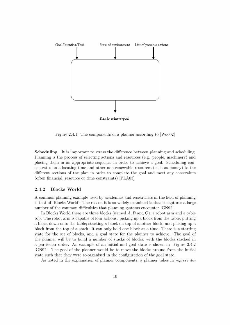
Figure 2.4.1: The components of a planner according to [Woo02]
Scheduling It is important to stress the difference between planning and scheduling.Planning is the process of selecting actions and resources (e.g. people, machinery) andplacing them in an appropriate sequence in order to achieve a goal. Scheduling con-centrates on allocating time and other non-renewable resources (such as money) to thedifferent sections of the plan in order to complete the goal and meet any constraints(often financial, resource or time constraints) [PLA03]
2.4.2 Blocks World
A common planning example used by academics and researchers in the field of planningis that of ‘Blocks World’. The reason it is so widely examined is that it captures a largenumber of the common difficulties that planning systems encounter [GN92].
In Blocks World there are three blocks (named A,B and C), a robot arm and a tabletop. The robot arm is capable of four actions: picking up a block from the table; puttinga block down onto the table; stacking a block on top of another block; and picking up ablock from the top of a stack. It can only hold one block at a time. There is a startingstate for the set of blocks, and a goal state for the planner to achieve. The goal ofthe planner will be to build a number of stacks of blocks, with the blocks stacked ina particular order. An example of an initial and goal state is shown in Figure 2.4.2[GN92]. The goal of the planner would be to move the blocks around from the initialstate such that they were re-organised in the configuration of the goal state.
As noted in the explanation of planner components, a planner takes in representa-
10

Figure 2.4.2: A simple ‘Blocks World’ initial state and goal state.
tions of the goal, state and environment. We can use the following predicates to createthe representation:
On(x, y) Block x is on top of block yOnTable(x) Block x is on the tableClear(x) The is no block on top of block xHolding(x) The robot arm is holding xArmEmpty The robot arm is not holding anything
[Woo02]Using these predicates, a description of the starting state in Figure 2.4.2 would be asfollows:
{Clear(A), On(A,B), OnTable(B), OnTable(C), Clear(C)}
The goal can be expressed in a similar manner:
{OnTable(C), On(B,C), Clear(B)}
To form the plan, we also need to be able to represent the actions. [Woo02] explainshow this can be achieved using the STRIPS formalism, in which each action has:
• A name - Which can have n number of arguments;
• A precondition list - A list of facts which must first be true in order for the actionto be performed;
• A delete list - A list of facts which will no longer be true after the action has beenexecuted; and
• An add list - A list of facts that will become true after the action is performed
Using this formalism, the ‘stack’ action could be described as follows:
11

Stack(X, Y )Precondition {Clear(y),Holding(x)}Delete list {Clear(y),Holding(x)}Add list {ArmEmpty, On(x, y)}
2.4.3 Planning techniques
Expressing plans in terms of formal logic and logic programs is an area that has beenstudied very widely. Possibly the most widely known of these is the situation calculus[SZ95], introduced by John McCarthy[MH86]. Gelfond and Lifschitz have also sinceargued that introducing classical negation into the stable model semantics is a desirableand effective way to represent planning [GL91].
The concept of answer set planning was formally explained in [SZ95]. In this paper,Subrahmanian and Zaniolo show that:
Given a planning domain D composed of an initial state and a set of actions,D can be translated to a logic program such that the given goal G is achiev-able in D if and only if a related goal G∗ is true in a stable model/answerset of the logic program that is obtained by the translation.
In the situation calculus [MH86], each action that is performed in a plan is rep-resented by the application of a function to a term that represents the current statein which the action is executed. Considering the ‘Blocks World’ example, one mightwrite the following in order to express the fact that block A is on top of block B afterperforming move(A,B) in state S0:
on(A,B, result(move(A,B)S0)))
[KS92]The disadvantage that many have found with the situation calculus is that an infinitenumber of applications of functions can be applied, whereas in planning the problem isone consisting of a finite number of actions.
One method of planning that is related to stable model semantics is satisfiabilityplanning. This is a formal method introduced by Henry Kautz and Bart Selman [KS92].This is essentially a technique to reduce a planning problem to that of finding a satisfyinginterpretation for a set of propositional formulas. Answer set planning is effectivelyan offshoot of planning by satisfiability, the difference being that instead of using thepropositional formulas, it uses ASP rules of the form defined earlier [Lif99].
2.5 How ASP has been used in planning
2.5.1 Introduction
This section visits probably the most significant application of Answer Set Programmingin the real world to date, and describes how and why ASP was used in this situation.
12

Some of the techniques used could prove to be relevant in the planning system thisproject proposes.
2.5.2 USA-Advisor
The USA-Advisor is a system that was designed to assist flight controllers plan forthe correct operations of shuttles in situations where a number of failures may haveoccurred [BGWN01]. Although the technology was designed to be used by many partsof the shuttle’s operations, the designers created the prototype for the Reaction ControlSystem (RCS). It is composed of a number of distinct components: a Java Graphicalinterface; an ASP program; a planning module; and an answer set solver, for whichthe designers elected to use smodels. The role of the Java interface is to receive andvalidate input (about tasks to be performed etc.) and then generate the ASP programwhich is then run through the solver. A planning module then builds a set of potentialplans, and the problem of finding whether this plan is valid or not is solved by simplychecking whether there exists a stable model of this plan from the smodels output. Theresult of this is then displayed in the Java interface [NBG+01]. The types of plans beinggenerated involve opening and closing valves which control the flow of propellant fromthe tanks to the jets of the RCS [Bal04].
Basic Planner The purpose of the planning module is to build the search criteriathat is used by the program in order to find a plan. The subsystem that the designersmodeled—the RCS—contained over 200 possible actions and often required very longplans to be made. As the RCS was itself composed of three subsystems, USA-Advisorcreated three plans that would run in parallel [NBG+01]. To illustrate in a very basicmanner how the system utilised ASP, consider the following three rules, which are themost fundamental ones in the planner.
i) 1{ occurs (A,T) : a c t i o n o f (A,R) }1 :− time (T) ,T <l a s t t ime ,system (R) ,not goa l (T,R) .
[NBG+01] explains that this rule states that at each moment in time, unless thegoal has been reached for that subsystem, then one action should be performed.
ii) goa l :− time (T1) ,time (T2) ,time (T3) ,goa l (T1 , l e f t r c s ) ,goa l (T2 , r i g h t r c s ) ,goa l (T3 , f o rward r c s ) .
This rule states that the overall goal of the RCS system has not been reached unlessall the goals of the subsystem have been achieved[BGWN01].
13

iii) :− not goa l .
Finally, the third rule states that for a model to exist, then the overall goal mustbe accomplished.
The basic planner is extended with the smart planner, which makes use of useful heuristicinformation, especially control knowledge. This is explained in detail in [BGWN01] and[NBG+01].
2.6 Alternatives to ASP for planning
2.6.1 Introduction
The case has been stated for the use of Answer Set Programming to be used in planningand scheduling domains, however there are a significant number of alternatives that havebeen used widely and successfully. Indeed, it is of course only relatively recently thatthe research and study into ASP has been in progress.
2.6.2 ‘Classical’ Planning
Classical Planning generally refers back to the early days of the planning problem start-ing in the 1950’s, when planning was seen simply as an extension of problem solving.Traditionally planning worked using classical search algorithms and made use of heuris-tics, developed ad-hoc. It has only really been in the last 15-20 years that researchershave considered the planning problem from such a different perspective [VV05]. Thefirst planner to be found in literature is thought to be the ‘General Problem Solver’(GPS), proposed by Allen Newell and Herbert Simon in 1957. Its intention was to bea ‘universal’ problem solver — in principle any formalized problem, such as theoremproof and geometric problems. Whilst it was capable of solving simple tasks such as theTowers of Hanoi that could be formalized, it was not possible for it to solve any realworld problems.
GPS worked by generating heuristics using means end analysis based on the userdefined objects and operations in order to solve problems. The program concentratedon observing each operation, creating subgoals and checking the output of the operationto get closer and closer to the overall goal [NSS59].
2.6.3 STRIPS style planning
STRIPS (Stanford Research Institute Problem Solver) is a formal language for expressingthe components of planning problems. The components of a STRIPS formalism and anexample using Blocks World can be seen in Section 2.4.2 of this document.
The two most commonly used algorithms that involve STRIPS representations aretotal ordered planning and partially ordered planning.
14

2.6.4 Total Ordered Planning
This technique has two opposite approaches:
Progression Algorithm
This method involves starting from the initial state and searched for the goal state bygoing through all the states that are generated by actions that can be executed fromthe current state the planner is looking at. [Wel94] explains that one problem with thisapproach is that given any state, there are a large number of actions available, meaningthat the branching factor in progression algorithms has often been considered to be toohigh to be rendered efficient. Many of the actions, while being valid, do not at all helpto attain the goal [Wel94].
Regression Algorithm
In a regression planning algorithm, the planner works backwards, from the goal state tothe start state, applying actions in reverse. At each stage, the planner is interested infinding the predecessor state.
The predecessor state can be generated by taking the given goal, deleting all of theaction’s add list items and adding all of the preconditions to the action. The predecessorcan then act as a subgoal, and we compute its own predecessors, and so on, until (ifsuccessful) the planner reaches a subgoal whose atoms are all true in the start state.
We can see that the major advantage of regression algorithms over progression algo-rithms is that they only consider relevant actions, that contribute toward the goal andsubgoals making it likely to run significantly faster [Wel94] .
2.6.5 Partial Order Planning
Partial Order planning is a technique that [Wel94] explains as representing plans in amore flexible way that allows the planner to delay decisions for longer. This is applicablewhen plans have to actions that need to be done, however the order in which they aredon is not important, e.g. a plan for booking a holiday would include the need tobook accommodation and to buy flight tickets, however there is no need to decide onthe order in which these are done. Hence algorithms which follow this technique arepartially ordered.
2.6.6 Hierarchical Task Network Planning
Hierarchical Task Network (HTN) planning is similar to STRIPS-style planners in theway that atoms are used to represent each state in the world and each action has acorresponding state transition. HTN planning differs with regards to what they plan forand how they plan for it [NAI+03].
STRIPS-style planners attempt to find actions that will have the desired affect,and make the preconditions for these actions subgoals. This is in contrast with HTN
15

Figure 2.6.3: The example used by [EHN94] of a task network
Figure 2.6.4: Decomposition of the ‘Go’ task from the task network in Figure 2.6.3[EHN94]
planning which uses task networks, which are essentially a number of tasks that needto be carried out, together with any constraints on the order in which they need to beexecuted [EHN94]. HTN’s can be represented clearly with a diagram.
A key problem with HTN planning is breaking up, or ‘decomposing’ tasks. A taskcannot be executed if it can be broken down into smaller tasks, i.e. is non-primitive,because performing that tasks requires a number of sub tasks to be executed. Therefore,tasks need to be decomposed into primitive tasks. For non-primitive tasks, the plannermust choose an appropriate method — which is a construct of the form (α, d), where αis a non-primitive task and d is a task network. When the method is chosen, the tasknetwork produced by the method replaces the non-primitive task in the network. Withinthat task network, the same process occurs unless it is a primitive task network, i.e. isonly composed of primitive tasks. If at some point it turns out that a plan is infeasible,the planner works backtracks and attempts the same process using other methods.
[EHN94] shows the process of task decomposition in Figure 2.6.3 and how the task ofGo can be decomposed in Figure 2.6.4. Hierarchical Task Networks are used in planningapplications such as O-Plan, a system mentioned earlier in Section 2.8.4.
16

2.7 Project Management Techniques
2.7.1 Introduction
This section investigates the techniques used by project managers to create and presentproject plans. It is desirable for the project to work in a familiar manner, possibly usingsome standard methods of showing plans to the user.
2.7.2 Project Planning and Scheduling
The project planning process is, according [Som01] an iterative process which usuallyfollows a pattern. The first stage in the process is the assessing of constraints, suchas deadline, resources available, etc.). Following this, milestones and deliverables aredecided upon. The next stage is that of settling upon a schedule and this can be updatedif and when the project is delayed or business needs change.
2.7.3 Gantt Charts
Gantt charts are a type of bar chart that illustrate the schedule of a project. As aminimum they show each task scheduled as a bar plotted against time, with the startand end date of each corresponding to the position of the bar. In some Gantt charts,dependencies between tasks are also shown, and it is also possible to display the currentstatus of the schedule as well as the planned schedule. For an example Gantt chart(which does show both dependencies as task completeness) see Figure 2.7.5.
Gantt charts can provide project managers a quick and simple understanding ofproject tasks and activities. This, combined with the rapidly increasing business use ofcomputers in the 1980’s heightened their popularity, and it is indeed now true that allmajor project management packages allow the users to create and/or view results in theform of Gantt Charts [Wil00].
One of the disadvantages of using Gantt Charts in software is the difficulty of showingall the complexities of a project, for example showing dependencies between tasks canmake them appear very cluttered, especially if there is a large number of tasks anddependencies to show.
2.7.4 PERT Network Charts
PERT (Program Evaluation and Review Technique) is a model often used for projectmanagement which is designed to show clearly the sequence of tasks and the criticalpath of a task (the path that must be finished on time for the project to be completedon time). Generally it is more suited to large, complex projects than a Gantt Chart isand in fact originated from the design and development of the United States’ Polarissubmarine in the 1950’s. A PERT Network Chart is usually drawn as a series of nodes,each representing an activity in the project. On each node there is a selection of data thatcan be shown, for example task name, duration, start date, finish date and slack/buffertime. This technique allows for much more detailed and flexible information that is
17

Figure 2.7.5: Example Gantt Chart (Source: Wikipedia)
available on a Gantt Chart. Some software packages, such as MS Project, support thecreation of PERT network charts from the projects that have been created. See Figure2.7.6 for an example PERT Network chart.
Figure 2.7.6: Example PERT Network Chart (Source: Wikipedia)
2.7.5 Staff Allocation Charts
Although not as formal a concept as Gantt Charts or PERT Network Charts, staffallocation Vs time charts are often used to display the allocation of staff to particularactivities [Som01]. This type of chart is very similar in principle to the Gantt Chart,each member of staff has a series of bars, shown in a horizontal fashion, illustrating thetime that they are allocated to a task. There may be occasions where some staff are not
18

allocated to any tasks. An example is shown in Figure 2.7.7.
Figure 2.7.7: Example Staff Allocation Vs Time Chart
2.8 Related Systems
2.8.1 Introduction
There are very few planning and scheduling systems available that are at all similar towhat this project proposes. Those that do exist are most commonly in use for complexsystems such as in spacecraft, and also are very specific to the mission that they havebeen designed for [FRCY96]. This section looks at a number of systems that are relevantin one way or another.
2.8.2 ASPEN
ASPEN (Automated Scheduling and Planning Environment) is a system designed by theAI group at NASA that provides a reusable set of software components that implementthe most commonly found elements of complex planning and scheduling systems. Itallows for both manual and automatically generated plans and schedules, and has apowerful GUI to view and edit plans and schedules that have been created. The GUIconsists of resource and state timelines, which also show planned activities/tasks. Tomodify a plan or schedule, users can drag and drop components [FRCY96].
19

Activity Database An activity, or task, is a step or an action in a plan, each havinga start time, end time and a duration. In ASPEN, these activities are stored in theActivity Database (ADB).
ASPEN does not use any form of logic programming to create its plans — it is pro-grammed in C++. [CRK+00] explains that plans and schedules are automatically gen-erated using an iterative repair algorithm. This essentially means that each conflict (i.e.violating a dependency) in a plan that has been initially created is addressed one at atime, until no more conflicts exist.
2.8.3 Microsoft Project
Microsoft’s MS Project is an extremely widely used project management tool that enablesmanagers to plan and schedule their activities. The clear difference from this projectand the other systems discussed is that the plans and schedules in MS Project arecreated entirely by the user, rather than being generated automatically by the system.The purpose of MS Project is to assist in the process of creating plans and allocatingresources, whilst also providing the benefits of tracking task progress, managing budgetsand analysing staff workload.
In relation to the system this project proposes, it is important to investigate thegraphical user interface and consider both how plans and schedules are represented tothe user and also how the details of a project are input into the system. [MAGAN01]argues that while MS Project and similar systems, such as SureTrak (Primavera SystemsInc.), and Autoplan (Digital Tools Inc.), are effective in being able to assist users inbreaking down the tasks into sub tasks and recording a plan, that task of plan creationis a complex and intensive one. [MAGAN01] goes on to claim that intelligent (i.e.automatic) planners could significantly speed up the planning process and increase itsaccuracy. This backs up this projects claim that there is a significant role to play forASP in this domain.
The main theme of the GUI is that it allows in almost all possible ways for visualinput. For example, plans created are shown in the form of Gantt charts, and oncecreated, the details such as start date, end date and duration can all be manipulated ina ‘drag-and-drop’ manner. However as well as this style, there is always an alternativeinvolving entering details such as dates textually. Another important concept that MSProject utilises is that of ‘wizards’ to aid users in data input. For example there is awizard to create each resource, a wizard to then allocate resources to task(s) and so on.
2.8.4 O-Plan
O-Plan [CT91] and O-Plan2 [TDK94] are AI planners which were designed to have anopen and flexible domain, and concentrated on the execution of plans as well as plangeneration. The first O-Plan development began in 1984, therefore the system has asignificant pedigree, argues [Dra95].
20

O-Plan2 is especially intended to be relevant in the following domains, according to[TDK94]:
• Project Management;
• Planning and control of supply and distribution logistics;
• Mission sequencing and space probe control.
In [TDK94], it is argued that because there are a broader range of users requiringplanning applications, it has become important to provide interfaces to AI planners thatcan be more easily understood by a wide variety of people. In the past GUI’s in AIplanning applications have been very specific and required expert knowledge of how theplanner worked.
The developers of O-Plan2 have based the GUI on two different views — The PlanView and the World View. The plan view is used for the user to interact with theplanner in terms of Gantt charts, PERT-charts, resource profiles etc. The world viewdisplays a domain orientated view of the state of the ‘world’. These ideas will all beimportant to consider in the development of the front-end of the planning applicationproposed.
2.9 Conclusions
The discussion up to this point in the report has helped gain a greater understanding ofthe background to this project. It has discussed the role of Answer Set Programming andcompared it to both procedural programming and other logic programming languages,stressing its differences and advantages in certain domains. We have also seen some ofthe history and theory behind the Stable Model Semantics and looked at several differentanswer set solvers which could potentially be used in this project.
It was then necessary to introduce planning and scheduling definitions and discussionsof how ASP has been used in a planning problem, namely the USA-Advisor, which is themost significant system developed using ASP to date. Sample ASP code was shown togive the reader some idea as to how planning problems can be solved using ASP. This partof the discussion has also shown the rather limited usage of Answer Set Programmingup to this point in time but also the potential for use in other domains like scheduling.
To gain an understanding of other theoretical and practical implementations of prob-lems within the planning and scheduling domain we looked at some of the alternativesthat are available to Answer Set Programming. This is outlined in a mostly chronologicalorder from the early days of ‘Classical Planning’ using ad-hoc algorithms through to thedevelopment of STRIPS based techniques and the effective Hierarchical Task Networks.
The next section of the review looked at techniques used regularly by project man-agers when dealing with planning and scheduling from a non technical viewpoint. This isan important aspect to consider as we can see one of the main purposes of this project isto allow people without the necessary technical expertise to be able to utilise the powerand potential of ASP in this domain – something that has already been shown exists.
21

This means that the system must use techniques and have features that are familiar anduseful for users such as project managers. For this purpose we discuss the uses, pros andcons of Gantt Charts, PERT Charts and staff allocation charts.
Finally, various related systems that have been developed were introduced and inves-tigated, such as ASPEN, a planning and scheduling system with a GUI that uses C++and an iterative repair algorithm – a very different approach to a similar problem thatthis report is primarily concerned with. We also looked at the similar O-Plan systems,which is relevant in the manner it displays plan views as Gantt Charts and PERT chartsand claims to be suited to project management applications. Finally we researched MSProject, which is very different in that it is by far the most commonly used tool byproject managers however does not automatically plan or schedule in the way we areproposing. It merely is used as an aid to display and manipulate plans. However thereis much to consider from such a successful and powerful application especially in termsof how results are displayed and how the user interacts with schedules once they arecreated.
22

Chapter 3
Requirements
3.1 Introduction
The overall purpose of this project is to create an application which will be able to createa project schedule based on the user defined input of tasks, staff, resources and othernecessary information. This section will use the information obtained from the literaturesurvey to draw up a list of features and abilities that the finished system must include.Appropriate scoping of the project must also be established, therefore there will also bea list of those features that are desirable, but not essential — the completion of thesewill be dependent on project progress and time constraints.
In this section there will be a general discussion to justify and explain some of the keyrequirements followed by a more formal definition of all the system requirements. Therequirements defined for the system in this document will be separated into functionaland non functional requirements following the technique described by [PRS02].
3.2 Constraints
Before considering the requirements that will be specified it is essential to discuss thevarious constraints that restrict the scope of the project. These restrictions have a directeffect on the number of requirements that are defined.
3.2.1 Time
A strict deadline is in place on the project of May 3rd 2007. This will understandablyaffect the features and functionality that will be included in the final system, so itis important not to introduce impossible or unfeasible requirements. An appropriatescoping of the system is necessary and there will be a reasonable number of features andfunctions that will only be included if time permits.
23

3.2.2 Finances
Financial constraints are unlikely to realistically affect the progress of the project as,unless any unforeseen circumstances should occur, there is not likely to be any essentialneed for finances. Although there is no significant financial support for the project, it isenvisaged that all tools required will be able to be obtained freely or cheaply.
3.2.3 Staff
Only one developer will be working on the project, therefore this will affect the scopeand number of potential features that can be included.
3.2.4 Access to multiple platforms
The development will be carried out on a Windows based PC and therefore any ac-cess if required for both development and testing purposes on other platforms such asMacintosh, Linux, Unix etc. would be extremely limited or non-existent.
3.3 Requirements Elicitation and Discussion
The target user for the system is primarily project managers, but also academics inter-ested for research purposes and possibly to a lesser extent a wide range of people whocould be interested in using an application to automatically create plans and schedulesfor personal purposes.
It was not considered feasible to gain sufficient access to a large enough number oftarget users such as project managers in order to construct and execute an effectivequestionnaire or survey process. For this reason, and as the project is largely an experi-mental software development project — concerned with how ASP could be used in thisdomain as much as wanting to create the proposed system for the purpose stated —most of the requirements have been developed from past research into ASP and similarproducts.
The basic requirements of the system could be established from the project de-scription provided by the project supervisor in conjunction with discussions with thesupervisor. This established the basic requirements such as the application having agraphical user interface that is intuitive to project managers and also that the plan mustuse answer set programming to find the potential plan(s).
Another basic requirement is that certain criteria should be met for a plan to beconsidered valid and feasible. These criteria are developed from relatively simple projectmanagement practice and include not accepting plans where not all the tasks are com-pleted, where a task is executed before a task dependency is completed, where a resourceis allocated to more than one task simultaneously, and so on.
A brainstorming session was suitable to establish some of the more specific anddetailed requirements such as what inputs the user should be able to specify and basethe plan upon. This requirement was also established by studying how MS Project
24

allows users to specify their plans as much of the ‘user input’ stage is the same principle;tasks must be created, resources defined and so on. MS Project allows users to givetasks names, durations and task dependencies so these are included in the requirements.Where MS Project requires that the user specify the start date for each task, this isclearly not relevant in this project as it will be generated automatically; however otherparameters were clearly required in order for the planning module to be able to schedulethe tasks, these were decided to be resources required, staff required and the staff skillsrequired. At this stage it is also possible to consider other features that could be includedas requirements but are for now left as potential extensions. For example, it was decidedto omit a specific staff required field which would have enforced one or more specifiedmembers of staff being assigned to a task, a feature which could be useful if perhapssome staff on a project have a preference for a certain task, or prior knowledge fromworking on a similar/previous task.
As MS Project is the most widely used project management tool available, it is im-portant that its techniques used in representing plans was observed, in order to decideupon the appropriate requirements for plan output. MS Project allows users to viewGantt Charts of the plans created as its primary representation, therefore it is consid-ered that there should be a requirement that plans in the system are represented inan identical or similar manner to Gantt Charts. It is also possible, in MS Project, todisplay PERT Charts. Due partly to the relatively experimental nature of the project,but due even more to the greater issue of the time constraints as outlined previously, theinclusion of PERT Charts in the system can be noted as a potential extension, eitherin this development if time permits, or for future developments of the system. A Ganttchart should be able to express everything that is required of the project.
An appropriate way to expand the scope of the project without having as manydifficulties with the time constraints would be to be able to export the created plan toa file readable by MS Project. This would allow users to create their plan easily andrapidly, and then view it in MS Project with all the views and abilities to change thatthey would be used to. This is included in the requirements although due to the timethat this would nevertheless take, it it listed as a lower priority.
There are a number of things which must be considered in terms directly of the userinterface. Having investigated alternative products, especially MS Project, it is consid-ered important that this system should incorporate a similar method of user interaction.Being partially aimed at a similar audience to that of MS Project, it is advantageous ifthere is little change from that application in terms of defining the necessary parame-ters. The process of creating the project tasks and various constraints upon them shouldalso be clear to see and be created in such a manner that the user can navigate quicklyaround. Should the interface be created in a way such that this process is slow andnot intuitive, users may find that they do not think it is worth trying to use this newproduct.
25

3.4 Requirements Definition
3.4.1 Functional Requirements
The following list describes the functional requirements of the proposed system. Thenumber in parenthesis after each requirements indicates whether it is considered highpriority (1), or lower priority (2).
1. There must be a graphical user interface (GUI) for the user to input the detailsabout a project (1)
2. There must be a way for the user to define the following inputs: (1)
(a) Project start date
(b) Maximum project duration
(c) Tasks
i. Task nameii. Task durationiii. Task dependenciesiv. Resources requiredv. Number of staff requiredvi. Staff skills required
(d) Resources
i. Nameii. Quantity
(e) Staff
i. Nameii. Skills
3. The application must be able to create a valid plan where possible, given a subsetof the above inputs. A plan is defined as valid if and only if all of the following aretrue: (1)
(a) All tasks are included in the plan
(b) The correct amount of time is spent on each of the tasks
(c) All tasks are finished by the end of the plan
(d) Tasks are scheduled in order of their dependencies (if any)
(e) The required resources for a task are allocated correctly, and in the correctamount
(f) Only resources of the right type are allocated to a task
(g) There are sufficient staff allocated to each task as defined by the user
26

(h) The staff allocated to a task have the required skills
(i) The plan should not allocated more resources than are available
(j) No member of staff is allocated to more than one task at any moment in time
4. The application must use an (ASP) answer set solver to generate plan(s) (1)
5. The application must have a number of ways to accurately present the followingaspect of the plan:
(a) Overall view of which tasks are performed on which days in the form of atleast a Gantt Chart (as is used in MS Project) (1)
(b) Staff allocation Vs time chart to show the tasks each member of staff isallocated to (1)
(c) View showing the tasks each resource is allocated to (1)
(d) Text based summary/explanation of the schedule (2)
6. If no plan is possible based on the constraints given by the user, the system mustrecognise this and report back appropriately (1)
7. The user should be prevented from providing simple inputs that will never resultin any possible plan, e.g.:
(a) Tasks with durations longer than whole project length (2)
8. The system should be able to select the plan which is shortest to present to theuser (1)
9. The user should be able to save plans to some format to be reloaded later (2)
10. The user should also be able to save or print Gantt charts and other plan views(2)
Desirable Features/Possible Extensions
• There could be a central store of tasks, resources and staff, such that they couldbe loaded and re-used in different projects
• If no plan could be created for a given set of inputs, explain as far as possible whynot, e.g.:
– Not enough resources on day x
– Not enough staff with skill y
– Dependency loop
• Allow for input of milestones separately to tasks
27

• Provide option to prefer plans where a buffer time is included at the end of certaintasks.
• Allow user to decide on what criteria a plan is selected and/or present the user anumber of different possible plans, e.g.
– The plan that will finish the project first
– The plan that uses the fewest resources
– The plan that uses the fewest staff
3.4.2 Non-Functional Requirements
The following non functional requirements are not specific features that should be foundin the final system but considerations that must be kept in mind in the design andimplementation of the project.
Performance
The system must be able to create an appropriate plan in a ‘reasonable’ amount of time,even for a large project with many tasks and resources. Due to the time saved overmanually creating a plan however, this time allowance may be significantly longer thanthe time usually allowed in some applications. This maximum time duration is thereforeset at one minute. It is imperative, however, that the system is stable whilst searchingfor a plan and it does not have an adverse effect on the user’s computer processes.
Usability
We must assume that while the target end user of the system will have at least basicgeneral computer skills, they will not have any knowledge of how ASP works. Navigationaround the application should be performed in a way that is standard to most computerusers and not be overly technical. Visually, it should be designed such that there isfamiliarity with other general purpose applications such as web browsers as well as toolssuch as MS Project. This will help the user understand how the system should beoperated and make it more intuitive. The issue of how a plan is generated will not beof concern to most users of the system so this should be hidden accordingly, and noknowledge of programming should be required at any point.
Extensibility
Due to the nature of the project (i.e. a relatively short development time comparedto the vast array of options that could be included in the system) it is imperativethat further development can occur with the system at a later date. This means thatstrict standards must be met in both the documentation of the system and the code.There should be a document detailing the class structure used and and code should becommented thoroughly and formatted in such a way that it is simple to understand.
28

Robustness
Although the project is largely experimental, it is important that the system is as robustas possible, i.e. if given invalid inputs, such as strings where integers are expected, thesystem must not fail immediately; and the user should be informed of their error. Thisis an important requirement as there is an increasing likelihood of further developmentbeing a possibility if the application is stable and not bug-ridden. It should be as closeas possible to being a ‘polished’ application bearing in mind the time constraints andwithout interfering with the primary requirements.
3.4.3 User Interface Requirements
• It should be clear to see the process of describing the tasks and constraints
• The process of creating the tasks and constraints for a plan should be as quick andsimple as possible whilst following all the functional requirements
• The user interface should use similar principles to project management applicationssuch as MS Project
3.5 Conclusion
This section has drawn up a list of requirements that must be kept to in developingthe proposed application. Due to the some of the described constraints on the project,the requirements have formed an appropriate and realistic scoping on the project, andfeatures that are not required by would be preferable or useful have been detailed, whichcan be included if time permits. These requirements will be carefully considered whenundertaking the testing process and evaluating the success of the project’s development.
29

Chapter 4
Design
4.1 Introduction
This chapter details the decisions made in developing and selecting solutions that satisfythe requirements set out and resolves conflicts within the requirements. At this stagethe design will be very high level and will not address implementation issues such astechnology/language or algorithm choice.
Research detailed in the literature survey chapter illustrated many possible tech-niques that have been used for planning and scheduling problems previously. Howeverthere are two considerations that must be stressed at this point:
• There have not been any previous systems that do quite what is proposed inthis project — some of the techniques discussed would be more appropriate forplanning systems such as autonomous robots, which, indeed, they have been usedfor. Project management is an area which is less associated with ASP.
• Perhaps the existing system that matches the requirements the closest is ASPEN,however this uses a C++ scheduling algorithm. As one of the main purposes ofthe project is to investigate how Answer Set Programming could be used in thisdomain, it is specified in the requirements definition that this project must useASP and calculate the plan using an answer set solver. Therefore any specificplanning techniques used by ASPEN are unlikely to be of special relevance in thedesign of this ASP based system.
• Similar design principles to MS Project, as the most popular project managementtool, should be at least considered. However, the significant difference of this appli-cation being an automatic plan and scheduling generator, must still be considered.
This section will continue to observe, discuss and seek to resolve some of the keychallenges and issues raised by the requirements.
30

4.2 System Architecture
Observing the requirements, it can be seen that there are three distinct stages that needto be considered:
1. Defining the project parameters (tasks, resources etc.)
2. Running this program through an answer set solver to get a valid plan
3. Presenting this plan to the user with a Gantt chart, staff allocation chart andtextual printout, or reporting that no plan was possible
The first significant design decision to make was how to separate the different requiredfunctions as outlined above. There is of course a requirement that the user must be ableto define the project parameters through a GUI — this is the motivation behind theproject. For this reason stage 1 must be separated from stage 2, as the user will enterthe parameters in a manner that an answer set solver would not understand. Thereforethere will need to be another component that converts the data input graphically by theuser into a valid ASP program. Now we have 4 required stages:
1. Defining the project parameters (tasks, resources etc.)
2. Converting this into an ASP program
3. Running this program through an answer set solver to get a valid plan
4. Presenting this plan to the user with a Gantt chart, staff allocation chart andtextual printout, or reporting that no plan was possible
To create a Gantt chart it will be necessary to use a language with significant graphicscapabilities in order to meet the requirements. Therefore to create the Gantt chart willrequire the ability to interpret the output of the answer set solver (typically a list of allthe stable models, but the exact format of this depends on the solver used) before it candraw the chart. It will also be necessary to select only one plan, as there could potentiallybe many thousands of possible plans discovered by the solver. The requirement is thatthe shortest plan out of all of these should be the default selection, although there is adesire if time permits to allow the user to choose from a wider variety of mechanismsfor plan selection. To make a compromise between the minimum requirements and theideal outcome, the system should select the shortest of all plans, although if there is morethan one that meets this criteria, there should be a secondary criteria that out of the setof all shortest plans, the plan which uses the fewest resources should be selected. Thisintroduces two extra stages, finalising the problem as a series of 6 separate functions:
1. Defining the project parameters (tasks, resources etc.)
2. Converting this into an ASP program
3. Running this program through an answer set solver to get a valid plan
31

4. Interpreting the output of the solver
5. Selecting one or more of the stable models to proceed with
6. Presenting this plan to the user with a Gantt chart, staff allocation chart andtextual printout, or reporting that no plan was possible
These six stages derived from the requirements specification allow us to identify therequired classes within the system being designed, explain their purposes and describehow they will interact with one another. As a minimum, the following classes appear tobe required:
• Main interface class. This class will the main user interface that the user will workwith during the process of creating and viewing a plan. There are likely to beseveral other classes that are called form the Interface class
• An ASP conversion class to convert between the data provided by the user to anASP program that can be executed
• An interpretation class to convert back between the output from the answer setsolver and concepts that can be understood programmatically and used to derivean appropriate Gantt chart and other representations.
To represent the project parameters before they are passed to the ASP converterobject it seems an intuitive and simple method to use a series of classes following objectoriented principles. These are:
• Project. This will represent the set of all tasks, staff and resources and essentiallybe the definition of the problem that will be sent to the answer set solver
• ProjectTask. Each task that the user defines in the project will be represented byan instance of this class.
• Resource. Each resource that is defined in the GUI.
• Staff. Each member of staff that is defined in the GUI.
It will also be necessary, in the interpretation stage of the application, to have aseries of classes that will store the plan(s) that have been suggested by the answer setsolver. The following classes will be used for this purpose:
• Plan. This class will store all the tasks, their start dates, and allocations of staffand resources.
• PlannedTask. This will represent each task in a plan, and will contain the startdate and the duration of the task.
• ResourceAllocation. This will represent the allocation of a member of the Resourceclass to any member of the PlannedTask class.
32

• StaffAllocation. This will represent the allocation of a member of the Staff classto any member of the PlannedTask class.
The final stage, the presentation of the plan in the form of a Gantt Chart andother models to show staff/resource allocations, will require a class for each type ofrepresentation. It is proposed at this stage to allow the user to view the project plan inthree manners:
• Gantt Chart. A traditional Gantt Chart in a similar style to that discussed in theliterature survey earlier.
• Staff Allocation Vs Time Chart. As discussed in the literature survey, this willbe similar to a Gantt Chart but for each member of staff will only show the tasksthey are allocated to.
• Summary. A text based breakdown of each day. For each day of the project, thiswill include a breakdown of each task being carried out on that day, what staff areallocated to it, and which resources are allocated.
If time permits in this development, or in future developments, it would be simple toinclude another class for PERT Charts or indeed any other type of output and pass intothat object the instance of the Plan.
The six main stages of the application and the relationships they have with the otherstages and the planned classes are shown in Figure 4.2.1.
Figure 4.2.1: How the planned classes will be used in relation to the six main stages ofthe application
33

4.3 Interface
The main concern with the Graphical User Interface is that the process of defining thedetails of a project are simple and relatively quick, whilst also allowing the user to specifyeverything that is required. Observing the requirements, it can be seen that there arethe following different functions that the GUI should allow the user to perform:
• Setting the project start date
• Setting the maximum project length
• Adding tasks and all the required fields
• Editing tasks
• Removing tasks
• Adding staff and skills
• Removing tasks
• Adding resources and quantities
• Removing quantities
• Generate plan
• Viewing Gantt Chart and other plan output forms
It is decided that defining the tasks, staff and resources for a project should allbe performed in a similar way, adhering to good user interface principles specified by[PRS02]. It is envisaged that the application will use a tab style component, with a tabfor each of those three mentioned. Each tab will contain a list box with an identifierof the tasks, staff or resources that are currently included in the project. The user willbe able to add and remove via simple buttons and if applicable edit an existing entrywhich is selected in the list box. There should also be a tab for the project details suchas project name, start date and maximum duration. Finally, a plan will be generatedon a ‘plan’ tab, which will also include information about which types of views can beshown.
4.4 Designing for testability
Due to the specific requirements about what constitutes a valid plan, and the wide arrayof potential project parameters that will be possible, testing the logic behind the ASPengine will be a complex task. For this reason it is considered preferable to isolate thetesting of the planning rules from the rest of the application until they have passedthe separate test plan. For this purpose the implementation of the ASP logic will becarried out completely separately from the implementation of the interface, converter
34

and interpreter. The converter, converting the user input into ASP facts, will be quitecomplex and using output from this in testing the ASP rules would not necessarily bereliable.
35

Chapter 5
Implementation
5.1 Introduction
This section describes in detail the implementation of the most important componentsof the application. It details the decisions made for choosing particular techniques, ortechnologies, over other alternatives and explains how various algorithms work. The firstsection presents the thought process and outcome of the decisions over which answer setsolver and object oriented programming language would be used. The most significantsection explains the process of creating the planning and scheduling rules and illustratinghow they work, using examples in many cases.
5.2 Technology Choices
5.2.1 Answer Set Solver
There are several considerations that must be kept in mind when choosing which answerset solver to use. Firstly, the time constraints for this project as specified in the re-quirements section mean that, as the developer has very little previous experience withwriting any ASP code, the language must be learned in a short space of time. For thisreason the most important aspect to bear in mind is how well documented the ASPsystem is. This effectively eliminated any of the possibilities except for smodels anddlv, as these by far the most well documented and used.
SMODELS
The main advantage of smodels is that the research carried out appears to show thatit is probably the best documented of them all. In addition to this it is the solver ofchoice for the supervisor of the project. Another potential advantage of using smodelswould be that it allows weight constraints, which will be discussed in a later section.A negative point is that there is no reliable and documented method of interface withsmodels from within an object oriented code environment. This means some form of
36

direct systems process call would have to be used to execute the solver, and it may provemore challenging to interpret the results.
DLV
A potential advantage of using dlv is the availability of the Java wrapper described inthe literature survey in Section 2.3.6. This would allow the ASP code to be written insidea Java class and would overcome the difficulty that has been mentioned by [Ric03] thathas been found when integrating ASP programs with an object oriented environment.However, it may be simpler for a number of reasons to separate the ASP back endfrom the GUI as much as possible. Firstly, to keep to the testing strategy mentionedin Section 4.4 it appears to be a beneficial idea not to embed the ASP in alongsideother functionality. Secondly, for purposes of further development and possible changesthat could be made in the future, separating the two functions would make it simplerto adapt, and if required even a different ASP answer set solver could be used withoutinterfering with the rest of the application logic.
Decision
It has been decided to use smodels as the answer set solver for this project. The mainreasons for this decision is the relative ease at which it is anticipated it can be learned andunderstood due to excellent documentation, literature and knowledge from this project’ssupervisor. It is also not considered to be a significant problem that there is no specificway to interface with it from any object oriented languages, as if necessary, it will bepossible to use a systems process call type command.
5.2.2 GUI Language
The GUI language refers to the main programming language which will be used forthe GUI and also for the storing and in fact the other stages mentioned in the designchapter such as conversion to ASP code and interpreting the stable models if necessary.The main features that any chosen programming language must have for this system isthat it is object oriented and has good graphics capabilities. A significant point whenconsidering the constraints mentioned in the requirements on time in this project is thatthe user is already knowledgeable to a certain extent in the language.
Java
Java is an object oriented programming language which is ideal in order to meet therequirement of having classes and object that represent the project before a plan iscreated and also to represent any plans generated. It also is a very familiar language tothe developer, which is something that is important.
37

C# .NET
The main argument for using this language is the fact that the developer has had a lotof experience with it, especially with creating graphical applications. Therefore some ofthe possible techniques to be used will be familiar.
Decision
The decision has been made to use Java as the programming language for the front end.Although the developer is competent in both the main languages considered (Java andC# .NET), it is felt there are a number of reasons why Java may just be preferable. Thereason main is that Java is platform independent, therefore can theoretically be usedon any platform rather than being restricted to Windows. This will help the projectbecome attractive to a wider range of people.
5.3 Implementation of main GUI
5.3.1 Introduction
Section 4.3 specified the required functions that the GUI should perform. From this,the tabbed style interface design was introduced. As the reader’s main interest is likelyto lie mainly within the other areas than trivial GUI code, this section will not go intodetails of what programming techniques were used in the implementation of the interface.However, the code listings for the interface can be found in the appendix with detailedcommenting for each class.
5.3.2 Calling smodels
The process of call the smodels answer set solver and attempting to create a planis initiated from the Interface.java class, upon the user selecting the “Generate plan”button. From the point when the user clicks this button the following sequence of tasksmust be performed:
1. Check project inputs are valid, i.e. at least one task exists.
2. Convert the project parameters into smodels format.
3. Write this code into an smodels file, along with planning and scheduling rules.
4. Pass the smodels file into the smodels solver.
5. Interpret back into Plan and PlannedTask objects.
The first stage in this process of plan creation is trivial, the second and third areperformed by the ConvertToSmodels.java class (see Section 5.4) and Stage 5 is achievedwith the InterpretStableModels.java class (see Section 5.6 ). This leaves the third stage,which is discussed here.
38

With no specific way to interface with smodels from Java, the in-built Java Run-time class was used. This class allows an application to interface directly with theenvironment within which the application is running. By retrieving the runtime ob-ject using Runtime.getRuntime() and calling its exec() method, with a string arraycommand argument, the given command is executed, in a separate process. The Con-vertToSmodels.java class adds all its code to a file which it names temp.sm, and theInterpretStableModels.java class reads from a file named results.txt. Therefore thecommand that is given to the exec method must pass temp.sm in as an argument anddirect the output to a file names results.txt. The command used is shown in the codebelow, in the array that is used (variables smFile and outFile are used to pass in thefile names in order that they can be changed easily if required):
St r ing osName = System . getProperty ( ‘ ‘ os . name ’ ’ ) ;S t r ing [ ] cmd2 = new St r ing [ 3 ] ;//Bui ld command array based on OSi f (osName . startsWith ( ‘ ‘Windows ’ ’ ) ){
System . out . p r i n t l n ( ‘ ‘ Detected to be running in Windows ’ ’ ) ;cmd2 [ 0 ] = ‘ ‘ cmd . exe ’ ’ ;cmd2 [ 1 ] = ‘ ‘/C ’ ’ ;
}else i f (osName . startsWith ( ”Linux” ) ){
System . out . p r i n t l n ( ‘ ‘ Detected to be running in Linux ’ ’ ) ;cmd2 [ 0 ] = ‘ ‘ sh ’ ’ ;cmd2 [ 1 ] = ‘ ‘− c ’ ’ ;
}else{
System . out . p r i n t l n ( ‘ ‘ Detected to be running in unsupported OS ’ ’ ) ;return ;
}
cmd2 [ 2 ] = ‘ ‘ l p a r s e ’ ’ + smFile + ‘ ‘ | smodels 5000 > ’ ’ + outF i l e ;
As is evident in the above code segment, the application is designed to be ableto call lparse/smodels if it is being run on the Linux platform as well as MicrosoftWindows. This requires the two programs to be installed correctly and/or either in thepath environment variable or in the same directory as where it is being run. Each OSrequires a different command to be able to make the system call.
As described in the literature review, lparse is the interface to smodels which allprograms must pass through prior to smodels. The numeric (‘5000’) argument tosmodels signifies that we wish the solver to return a maximum of 5000 answer sets; thedefault is to return only one. Initially the implementation used the zero argument tosignify we wished the solver to return all answer sets, however there were serious issueshere with stability. In one test that was carried out on a moderately complex project,
39
the answer set solver took many minutes and produced an output file of over 4GB ofstable models. Therefore there had to be a limit set, even though it means potentiallya number of viable plans will not be considered by the system. Further testing needsto be carried out on a greater array of machines and environments to establish whetherthis is the optimum number or whether the users should be able to select it themselves.Following the calling of the exec() method, the process.waitFor() method is called,halting all subsequent code until the process is complete. This ensure that we do notattempt to interpret the results before the results have been generated.
5.4 SMODELS converter
The purpose of the smodels converter class (ConvertToSmodels.java) is to convert in-tuitive concepts such as tasks, resources and staff, into smodels facts which will be usedby the answer set solver to create valid plans. We recall that a fact in any ASP programcan be defined as a rule with and empty body, and where the head is a single disjunct(i.e. one term). The facts created will be combined with the rules in the following sectionwhen run through the solver.
5.4.1 Set of available facts
Depending on the inputs given by the user, a subset of the following facts are created bythe ConvertToSmodels.java class. For example, if the user does not include any resourcesin the project, none of the facts which describe resources would be included. Here thefacts are defined and explained briefly (full details on how they work can be found lateron):
• days ( 1 . .X) .
This defines a fact for each day that the project is running for (up to the maximumX set by the user).
• s t a f f (S) .
This is a fact declaring each member of staff S created by the user.
• task (T) .
This creates a fact for each task T in the project.
• s k i l l (S ) .
This creates a fact for each skill S that has been defined in the project.
• r e s ou r c e (R) .
This creates a fact to declare each resource R defined in the project.
40

• type (P) .
This creates a fact to declare each resource type P defined in the project.
• r e s ou r c e type (R,P) .
This specifies that resource R is of type P .
• s t a f f s k i l l (S ,K) .
This tells smodels that staff member S has skill K.
• s t a f f n e ed ed (T, X) .
This specifies that the task T requires X number of staff to be working on it at alltimes.
• t a s k s k i l l (T,K) .
This fact declares that task T requires staff to have skill K if they are to be assignedto it.
• durat ion (T,X) .
One fact for each declared task T specifies how long it will take, X.
• task dependency (T,T ’ ) .
This declares that task T requires task T ′ to be completed before it may start.
• t a s k r e s ou r c e (T,R,X) .
This fact is used to specify that task T requires X amount of resource R.
• t a s k s t a f f (T, S) .
This fact declares that task T requires staff S to be assigned to it.
• max tr ( 1 . .X) .
This specifies the possible range of values in the third parameter of the task resourcepredicate. The need for this is explained later on.
It is also necessary to include a constant, representing the last day available in theproject:
const end = X.
This helps make some of the rules described in the next section simpler.
41

5.4.2 Conversion
Using the smodels answer set solver instead of dlv meant that there was no specificway to call the process from within the Java code. For this reason it was necessaryto write the smodels file that was to be parsed into a distinct file, ‘temp.sm’. TheConvertToSmodels.java class is passed the instance of the Project class that containsall the tasks, staff and resources and writes it to the file using the Java BufferedWriterclass.
The conversion is carried immediately as the class is instantiated, where a methodis called from the constructor to write all of the required facts as specified in Section5.4.1. Each of these methods uses helper functions from the project class to return thelists necessary to gather all the data. They then write the required rules to the end ofthe temp.sm smodels file. An example of one of these conversions, namely adding theduration facts for each task, is shown below:
private void addTaskDurations ( ){
St r ing input = ”” ;ArrayList ta sk s= pro j . getTasks ( ) ; // ge t a l l p ro j t a s k sfor ( int i = 0 ; i < ta sk s . s i z e ( ) ; i++){// f o r each ta s k
input = input + ” durat ion ( ” ; //add p r ed i c a t e name durat ionProjectTask t= ( ProjectTask ) ta sk s . get ( i ) ;S t r ing t2 = t . getName ( ) . r ep l a c e ( ’ ’ , ’ ’ ) ; // r ep l a c e spacesinput = input + t2 . toLowerCase ( ) + ” , ” + t . getLength ( ) ; //add
ta s k name and l en g t hinput = input + ” ) .\n” ;
}appendToFile ( input ) ; //add t h i s t e x t to the end o f . sm f i l e
}
5.5 SMODELS planning/scheduling rules
5.5.1 Introduction
The rules that determine the possible plans use the facts discussed briefly in Section5.4.1 and are appended to the same .sm file at the same time. A plan or schedule isa series of ground terms (where constants such as task names are included instead ofvariables, represented by terms starting with a a capital letter) where a subset of thefollowing predicates are satisfied:
• t a s k s t a r t (T,D) .
This signifies that task T will start on day D.
• s t a f f a l l o c a t i o n (S ,T,D) .
This means that staff member S is allocated to task T on day D.
42

• r e s o u r c e a l l o c a t i o n (R,P,T,D) .
This specifies that there is a resource allocation of resource R (which is type P )to task T on day D.
These predicates cannot be specified by facts of course, as the purpose is that thealready mentioned facts that are created from the user input will be used to find setsof these rules that can be satisfied. These rules are the essence of the planning andscheduling of the system. Due to the powerful notation that is possible in smodels, allof these rules can be explained in this document.
Prior to this explanation, however, it is helpful to explain some of the syntax andlanguage features that are used.
5.5.2 Cardinality Constraints
A cardinality constraint is described by the following form:
L{a1, ..., an,not b1, ...,not bm}Uwhere ai and bj are atoms and L and U are integers. In the case that either L or U areabsent their value is either −∞ or ∞ respectively [Bar03]. The usual case is that L andU are integers (a limitation of the smodels implementation, semantically these couldbe real numbers) representing the lower and upper bounds of the constraint. Such aconstraint shown is satisfied by any stable model for which the cardinality of the subsetof literals satisfied by the model is between L and U inclusive [NS00].
We can write a rule such as:
a(X, Y ) : −1{p(X), f(X)}1, 1{f(Y ), g(Y )}2.
which says that if exactly one of p(X) and f(X) is found in a stable model, and either1 or 2 of f(Y ) and g(Y ) is in the model, then a(X, Y ) is also contained in the model.
Conditional literals
A concept which is often found when using cardinality constraints is that of conditionalliterals. These are used in order to express sets of literals in a compact way. A conditionalliteral is of the form
p(X1, ..., Xn) : p1(Xi1) : ... : pm(Xim).
where the predicate p is referred to as the enumerated predicate and each pi is knownas a condition of p.
As an example, given the facts col(c1, c2, ..., ck), the sequence:
color(v, c1), color(c, c2), ..., color(v, ck)
can be represented by the conditional literal:
color(v, C) : col(C).
This illustrates how much more compact rules can be written with the introduction ofconditional literals [Bar03].
43

5.5.3 Constraints or ‘killer clauses’
A killer clause is a useful technique that is based on a rule which has an empty head,e.g.:
: −a, b.
This is actually an abbreviation of the following:
x : −a, b, not x.
This rule acts as a constraint; it ‘kills’ all answer sets where a and b are both true,or in the general case, where everything in the body is true.
5.5.4 Hide
A relatively simple formality that is described here is that of the ‘hide’ declaration, whichtakes the form of:
hide p(X1, ..., Xn).
This tells smodels not to output atoms of the n-ary predicate p when outputting thestable models. This helps analyse only the important predicate for both testing purposesand it also significantly speeds up the InterpretStableModels.java class process.
5.5.5 The rules
We recall from Section 5.5.1 that there are (up to) three predicates which the plans arebased upon — task start time, staff allocation and resource allocation. We will look athow these work and why particular techniques were chosen individually.
Task Start
This was the logical predicate to begin with during development. The first task wasto attempt to enforce the answer sets that the solver produces would order the tasksin a valid order without considering resources or staff required. To do this, we had toconsider the following parameters:
• There must be sufficient days directly after the task start day to complete the task(before end of project time).
• A task must wait for any tasks that is may be dependent on to complete before itcan begin.
The first rule in the smodels file that is executed looks like this:
1 { t a s k s t a r t (T,D) : day (D) } 1 :− task (T) .
44

Describing this in a logical manner, this rule does the following:
For all tasks T , there must exist exactly one day D that task T starts on.
This begins to illustrate a particular strategy that was used in the development of theASP rules. This was to start with a simple, ‘base case’ of assignments and then use‘killer clauses’ to eliminate any instances that violate any of the constraints that mustbe met. So this rule will be the base case, it creates an assignment of one day (any dayout of the available project days) to each and every task. There is a copy of the outputfrom the smodels solver available in Appendix A.1.1 which shows the different possible‘plans’ that would be available in a small example domain of two tasks and two availabledays.
The output shows that as each task can be started on either day 1 or day 2 there arefour possible combinations overall, meaning four answer sets, one for each combination.Now let us consider the constraints on the days when a task can start. Firstly, recallthat there must be sufficient days in which the task can be completed directly (andconsecutively) after the task start day. The following rule is our second:
:− task (T) , day (D) , day (X) , t a s k s t a r t (T,D) , durat ion (T,X) , D + X −1> end .
Describing this in a logical manner, this rule states the following:
For all tasks T , with day D on which it is assigned to start, this stable model is invalidand ‘killed’ if the start day D plus the duration X of task T , is past the end of the total
project length (‘end’ is declared as a constant, see Section 5.4.1).
The input and output text for this test is also available in Appendix A.1.2, with the samedata except this time including durations. One task is given a duration of 1 (thereforecould be started on day 1 or 2) and the other is given a duration of 2 (therefore it isconstrained to start on day 1).
Comparisons of this constraint method could be made to the iterative repair algo-rithms used in some of the systems discussed in the literature survey, such as ASPEN(see Section 2.8.2). In these algorithms a plan is initially created before an algorithmgoes through ‘repairing’ violations of constraints. The formation however of those typesof procedural algorithms is far more complex that this ASP method.
The final constraint on the choice of start days is that if a task is dependent on othertasks, then they must all be completed before the task can begin. The following ruleused in the smodels procedure achieves that outcome:
:− task (T) , day (D) , task (T2) , day (D2) , t a s k s t a r t (T,D) ,task dependency (T,T2) , t a s k s t a r t (T2 ,D2) , day (X) , durat ion (T2 ,X) ,D2 + X > D.
45

Again, let us look at the rule in a logical manner:
For all tasks T that depend on a different task T2, if T2 completes any day after thestart of T , then this stable model is killed.
This test can be viewed in full details in A.1.3. It is successful in eliminating any plansin which the order of tasks executed violates any task dependencies.
Finally there is an additional predicate, which is used as a helper for many of theother rules:
t a s k a l l o c a t i o n (T,D) :− task (T) , day (D) , day (D2) , durat ion (T,X) ,t a s k s t a r t (T,D2) , D < D2 + X, D >=D2.\n
The logical meaning of this predicate, is, if found in a stable model, that task T is be-ing carried out on day D. The difference from task start is that there is a task allocationfor each day on which the task is being carried out, not just the first day.
Staff Allocation
There were several issues to consider in successfully allocating staff to relevant tasks.The following constraints had to be enforced as specified by the requirements:
• The exact number of staff needed for a task should be assigned to it on each dayof execution
• Each member of staff should have the required skills
• No member of staff should be allowed to be allocated to more than one task at atime.
• Any specific staff required for the task should also be allocated to it (added fromoriginal requirements)
In accordance with the same white box testing strategy previously outlined the staffallocation ASP functionality will be tested on its own; i.e. only the base case rule fortask start will be included initially.
As with the task start predicate, the same strategy of having a base case and theneliminating those models where constraints are violated was implemented. However, toachieve the correct functionality, the staff allocation predicate was broken down into thetwo different forms.
To signify that a specific member of staff has been allocated as enforced by theuser, the predicate staff_allocation_fix is used, and for all other staff allocations(‘non-specific’, based on skills) staff_allocation_var is used. There is a base case foreach:
s t a f f a l l o c a t i o n f i x (S ,T,D) :− s t a f f (S) , task (T) , day (D) ,t a s k a l l o c a t i o n (T, D) , t a s k s t a f f (T, S) .
46

This allocates any member of staff to a task if the task staff(T,S) predicate is true forthem and that task.
X { s t a f f a l l o c a t i o n v a r (S ,T,D) : s t a f f (S ) } X :− task (T) , day (D) ,t a s k a l l o c a t i o n (T,D) , s t a f f n e ed ed (T,N) , X = N.
This rule is used to allocate ‘non-specific’ members of staff where they are assignedbased on any skills required. As can be seen, this makes use of the smodels cardinalityconstraints explained earlier. Unlike the task start predicate, we see here the use of avariable, X, as the boundaries of the cardinality constraint. To understand this ruleit is necessary to recall the meaning of task allocation(T,D), which is that task T is inexecution on day D.
The staff allocation predicate assigns a staff S to a task T on a particular day D.Although the design of the implementation enforces a staff allocation to last the entirelength of a task, it is nevertheless necessary to include the day in the allocation. Thismeans that there is a staff allocation for each member of staff allocated, and for eachday of its duration. In future development there could be a further option to allow staffto work for any number of days on a job, so this is left in for extensibility and also forsimplicity, although it does mean that there is usually more output from the smodelsprogram that has to be checked through (one for each day of each staff allocation).
The logical meaning of the ‘var’ base case rule can be understood as:
for each task and day, if that task is executing on that day, and that task needs Xnumber of staff, assign X staff to a task allocation for that day and task.
A test for this is available in Appendix A.1.4. The test uses two tasks with two availablestaff members. One task requires two tasks and the other needs just the one. The outputof this smodels program shows that each stable model allocates sufficient staff to eachtask but it includes stable models where staff are allocated to two tasks simultaneouslyand does not deal with any skills that may be required.
To then make the interpretation and clarity much simpler, and as there is no logi-cal difference in terms of the eventual plan between the two types of staff allocations,two more rules are added, which simply say that either form of staff allocation can beconsidered as a staff allocation in its ‘general form’:
s t a f f a l l o c a t i o n (S ,T,D) :− s t a f f (S) , task (T) , day (D) ,t a s k a l l o c a t i o n (T,D) , s t a f f a l l o c a t i o n f i x (S ,T,D) .
s t a f f a l l o c a t i o n (S ,T,D) :− s t a f f (S) , task (T) , day (D) ,t a s k a l l o c a t i o n (T,D) , s t a f f a l l o c a t i o n v a r (S ,T,D) .
This avoids having to check for two different types of staff allocation when interpret-ing the stable models that are output, and the same logic can then be applied on each.It is also necessary for other rules.
47

The following rule is also necessary as a constraint to remove any stable modelswhere a member of staff has been assigned to a task as both a specific member of staffallocation and a non-specific allocation (if a user specifies 2 non-specific people and oneparticular person, this should mean three people in total):
:− s t a f f a l l o c a t i o n v a r (S ,T,D) , s t a f f a l l o c a t i o n f i x (S ,T,D) , s t a f f (S) ,task (T) , day (D) .
It was mentioned earlier that a limitation of this development is that a staff allocationcannot be for any other length of time other than that of the entire duration of theproject. This is enforced with the following rule:
:− task (T) , day (D) , t a s k a l l o c a t i o n (T,D) , s t a f f (S ) ,s t a f f a l l o c a t i o n (S ,T,D) , day (D2) , not eq (D,D2) ,t a s k a l l o c a t i o n (T,D2) , not s t a f f a l l o c a t i o n (S ,T,D2) .
The next stage is to eliminate models where allocated staff do not have the requiredskills. The following rule implements this functionality:
:− s t a f f (S) , task (T) , day (D) , s k i l l (K) , s t a f f a l l o c a t i o n (S ,T,D) ,t a s k s k i l l (T,K) , not s t a f f s k i l l (S ,K) .
Recall that task skill(T,K) is a predicate created by the ConvertToSmodels.java classfor each required skill that the user adds to a task and that staff skill(S,K) is predicatecreated for each skill that a member of staff has. This is then a fairly simple killerclause to remove any staff assignments for which a required staff skill(S,K) K fromtask skill(T,K) cannot be found for the staff S. A test for this rule can be found inAppendix A.1.5, showing there only exist staff allocations for staff that have the requiredskill for a task.
The other constraint that must be adhered to is that no member of staff can beallocated to more than one task on any particular day. This can be achieved by againusing a killer clause:
:− s t a f f (S) , day (D) , task (T) , task (T2) , not eq (T,T2) ,s t a f f a l l o c a t i o n (S ,T,D) , s t a f f a l l o c a t i o n (S ,T2 ,D) .
This rule states that we kill any answer sets where there is a staff S that has a staffallocation for two different tasks on any day D. The equal function eq is inbuilt into thesmodels program. A test case for this is available in Appendix A.1.6.
48

Resource Allocation
The final group of rules is those required to accurately assign resources to tasks. Al-though at first glance the challenge of resources may seem identical to that of staff, it isin fact different, and indeed slightly more complicated. This is due to the fact that withstaff, there is only one of each ‘type’ of staff, i.e. there are not five John Smiths in theway that with resources there may be five computers, for example. It is also desirablefor the user not to have to define each individual resource separately (i.e. computer1,computer2) as it would not matter which computer would be assigned to a task. Ad-ditionally, in the requirements and design it is specified that each resource would bedefined along with the quantities available.
It was decided to include an extra variable for resource type. This would now workby defining each resource individually, such as computer1, computer2,... and so on, andincluding a fact (as shown in Section5.4.1 ) for each type and also a resource type factfor each resource, which links the resource to whichever type it is. The fact maxtr isused to tell the solver the possible entries in the quantity parameter for task resourcefacts. // Again, a base case is created:
X { r e s o u r c e a l l o c a t i o n (R,P,T,D) : r e s ou r c e (R) } X :− task (T) ,day (D) , type (P) , t a s k r e s ou r c e (T,P, Z) , max tr (Z) ,t a s k a l l o c a t i o n (T,D) ,X=Z .
In this case, this allocates Z number of resources to each task, on each day it is beingexecuted for each different type of resource it requires, where Z is the number of resourcesrequired. Recall that a task resource is defined for each different type of resource needed,with the quantity of that resource as Z. Using the cardinality constraints, it thenassigned exactly that number of any resource to that task on that day. At this stage,as it is the base case, we are not concerned with assigning the correct types of resources,that can now be simply added as a constraint. The test case for this rule can beseen in Appendix A.1.7, showing that there are always the correct number of resourcesassigned to each task, however there are many stable models where the incorrect typeof resource is allocated to a task. Also there are many occasions where more resourcesof a particular type are allocated at a certain time than are actually available (i.e.simultaneous allocation). Note at this stage also that unlike with staff, it is consideredacceptable for a resource to be allocated for only part of the duration of a task, as longas the correct number of each type are allocated for each day. It would be down to thoseexecuting the tasks as to whether it is deemed necessary to care about which computeris computer1 and which is computer2 or so on or whether it is only important that it isa computer. Now we look at the first constraint, which is to remove stable models wherethe wrong type of resource is allocated to any task. As we have allocated exactly thecorrect number needed for each task resource, we know that if one of these allocationsis not the correct type, then there are insufficient allocations for that resource on a day.This means it can be ‘killed’, something the following rule achieves:
49

:− r e s o u r c e a l l o c a t i o n (R,P,T,D) , day (D) , task (T) , type (P) ,r e s ou r c e (R) , not r e s ou r c e type (R,P) .
It should be relatively simple now to see how this works. If there is a resource allocationof R to T on D, and no resource type can be found that matches what is required, themodel is killed. An alternative but equivalent rule with identical results would havebeen:
:− r e s o u r c e a l l o c a t i o n (R,P,T,D) , day (D) , task (T) , type (P) , type (P2) ,not eq (P, P2) , r e s ou r c e (R) , r e s ou r c e type (R, P2) .
As there can only be one type for each resource, if the type of the allocated resourceis something other than the type required, it is clearly not of the type that is required.A test case is again available, in Appendix A.1.8 using the first of these two rules. Thenumber of stable models, or valid plans, is down to 4 from 14 in the base case, and nowonly the correct type of resources are allocated to each of the tasks.
The final rule included is required to prevent any single resource from being allocatedat any one time. It works in a similar manner to that which prevents a member of stafffrom being allocated to two tasks simultaneously:
:− r e s o u r c e a l l o c a t i o n (R,P,T,D) , r e s ou r c e (R) , task (T) , day (D) ,task (T2) , not eq (T,T2) , type (P) , r e s ou r c e type (R,P) ,r e s o u r c e a l l o c a t i o n (R,P,T2 ,D) .
Again a test case that shows how this eliminates invalid stable models can be seenin Appendix A.1.9. We use a different input to that of the test for the base case asno resources were allocated to multiple tasks simultaneously in that. The input usesthis time means that each task requires the a pen, so the situation could occur wherea particular pen is allocated to both tasks on a day, but does not due to the constraintrule above. The project is shortened to one available day to clarify this test and reducethe significant output that otherwise occurs. Although the preferred testing strategyis only to include the base case to test each individual constraint rule added, it is thistime necessary to include the ‘wrong resource type allocated’ rule to be able to see theresults accurately. The output shown shows how the only two possibilities are found bysmodels, and neither pen is allocated to both tasks simultaneously.
5.6 Stable models interpreter
The purpose of the interpreter class (InterpretStableModels.java) is to interpret theoutput from the smodels solver into a form that can be understood and manipulated bythe java classes to carry out stages 5 and 6 that were outlined in the system architecturesection of the design chapter. This is the choice of a particular plan and the presentationof this in a Gantt Chart and other visual forms. The form that the smodels answer set
50

solver outputs the stable models make interpreting the plans quite a challenge. Generally,the format is as follows:
smodels version 2.26. Reading...doneAnswer: 1Stable Model: [List of task_start, staff_allocation, resource_allocationpredicates in the model that represent a possible plan choice - all on one line]Answer: 2Stable Model: ......Answer: NStable Model:...
As detailed in chapter 4, there is a Plan class available that will represent a plan, andstore all the details about which tasks are scheduled at which times, and which staff andresources are allocated. It is now required to convert the output above into a list of thesePlan objects, after which it will be possible to discard all but one plan (the shortest, asdescribed in requirements) and store that to display to the user when required.
It is described in Section 5.3.2 how the smodels process is called and demonstratedhow the output is directed to a text file. The text file is where the output in thepreviously described format appears. When the Interpreter is created it is passed areference to the file that contains the stable models, and the first step is to instantiatea BufferedReader and read each line of the text file (which is automatically named bydefault results.txt). Each line is checked to establish whether it is the start of a stablemodel and if it is, it is added as a new element to an ArrayList. As described above,each stable model is on its own line, and begins with the string Stable Model: thereforeit is a relatively simple check.
At this stage, the interpreter holds simply a list of strings that represent the plans,the next task is to create a Plan object for each of these and add to each plan a set ofPlannedTask objects, one for each task to be performed, and a series of StaffAllocationand ResourceAllocation objects. Recall that the PlannedTask class holds the followingproperties:
• String task
• int startDay
• int length
The interpreter loops through the list of strings one at a time and uses a String-Tokenizer object, splitting the input string by each space into a series of string tokens.As all valid plans will have exactly one task start for each input task, all PlannedTaskobjects are created before actually analysing the text line for a stable model. Each taskis then also added to the Plan object, in the following manner:
51

for ( int k = 0 ; k < answerSetL i s t . s i z e ( ) ; k++){
Plan plan = new Plan ( ) ; // c rea t e a plan o b j e c t f o r t h i s modelSt r ing temp = ( St r ing ) answerSetL i s t . get ( k ) ;St r ingToken ize r s t = new Str ingToken ize r ( temp) ; // t o k en i z e over
t h i s s t a b l e model s t r i n gArrayList a l lTask s = pro j . getTasks ( ) ; // ge t l i s t o f t a s k s in t h i s
p r o j e c tfor ( int i = 0 ; i < a l lTask s . s i z e ( ) ; i++){// f o r each ta s k in p r o j e c t
ProjectTask task = ( ProjectTask ) a l lTask s . get ( i ) ;PlannedTask gt = new PlannedTask ( task . getName ( ) ) ; //Create a
PlannedTask o b j e c t f o r the d e t a i l s o f the t a s k a f t e rp lanning
plan . addTask ( gt ) ; //add t h i s t a s k to p lan o b j e c tgt . setLength ( task . getLength ( ) ) ; // s e t the l e n g t h o f the
PlannedTask o b j e c t to whatever i s in the ProjectTask o b j e c t}. . . // t h i s code f o r adding d e t a i l to t a s k s exp l a ined l a t e r . . .
}
Following this the StringTokenizer is used. Given the following example stable modelsoutput, the StringTokenizer would split it up as follows:
Stable Model
Stable Model: task_start(b,2) task_start(a,2) resource_allocation(pen1,pen,b,2)resource_allocation(computer1,computer,a,2)
Tokens
StableModel:task_start(b,2)task_start(a,2)resource_allocation(pen1,pen,b,2)resource_allocation(computer1,computer,a,2)
The StringTokenizer has a nextToken() method that returns the next token, allowingthe interpreter to go through each at a time, and perform the relevant action dependingon which predicate (if any) it finds. As described in Section 5.5.1 there are three differentpredicates that represent a plan, which means three different types of action, plus theaction of doing nothing if the token is not either of these predicates. The rest of themethod then works in the following manner:
52

while ( s t . hasMoreTokens ( ) ) {St r ing tok = s t . nextToken ( ) ; // read next tokSystem . out . p r i n t l n ( tok ) ;i f ( tok . s tartsWith ( ” t a s k s t a r t ( ” ) ){
foundTaskStart ( plan , tok ) ;}else i f ( tok . s tartsWith ( ” s t a f f a l l o c a t i o n ( ” ) ){
f oundS ta f fA l l o c a t i on ( plan , tok ) ;}else i f ( tok . s tartsWith ( ” r e s o u r c e a l l o c a t i o n ( ” ) ){
f oundResourceAl locat ion ( plan , tok ) ;}
}plan . s e t S t a r t ( pro j . getStartDate ( ) ) ; // s e t s t a r t date o f p lanp lanL i s t . add ( plan ) ; //add t h i s p lan to l i s t o f p lans found
Each of the three methods that are called (for task start, staff allocation and re-source allocation) use similar techniques to achieve their ends. They break up the inputof the token tok into each parameter and update the plan object accordingly. Forexample, the foundTaskStart(plan,tok) method is shown below:
St r i ngBu i l d e r sbTask = new St r i ngBu i l d e r ( ) ;S t r i ngBu i l d e r sbStar t = new St r i ngBu i l d e r ( ) ;int taskend = 0 ;for ( int i = 11 ; i < tok . l ength ( ) ; i++){// loop through token from s t a r t o f t a s k name
i f ( tok . charAt ( i )== ’ , ’ ) // then we have found end o f t a s k name{
taskend = i ;break ;
}sbTask . append ( tok . charAt ( i ) ) ; //add t h i s char o f t a s k name
}for ( int i = taskend + 1 ; i < tok . l ength ( ) ; i++){// loop from end o f t a s k name i e s t a r t o f t a s k s t a r t time
i f ( tok . charAt ( i ) == ’ ) ’ ) // then we have found end o f s t a r t timebreak ;
sbStar t . append ( tok . charAt ( i ) ) ;}PlannedTask tsk = plan . getTask ( sbTask . t oS t r i ng ( ) ) ; // g e t s the
PlannedTask crea ted e a r l i e r in i n t e r p r e t i n g proces s us ing the t a s kname found
i f ( t sk == null )System . out . p r i n t l n ( ” nu l l ” ) ;
t sk . setStartDay ( In t eg e r . pa r s e In t ( sbStar t . t oS t r i ng ( ) ) ) ; // s e t s thes t a r t time we have j u s t found
53

The methods for foundStaffAllocation(plan,tok) and foundResourceAllocation(plan,tok)add their respective objects StaffAllocations and ResourceAllocations to the plan object,each containing the name of staff/resource, name of the task allocated to, and the dayfor which the allocation refers to. This leaves the interpreter in a position to choose theplan that will be selected to show to the user. As mentioned earlier, in the requirementssection, it was decided that time constraints on the project would limit this to force thechoice to be the shortest of all the plans in terms of which plan completes all the tasksat the earliest point. In cases where there is not a unique shortest plan, a list of equalshortest should be found and then from that list, the one which uses the fewest resourceswould be chosen (note this means the fewest distinct resources, not the fewest resourceallocations). The requirements also state that this is one specific area that should beeasily adapted to allow for extensibility if in future developments it would be possibleand desirable to use a different criterion to select a plan. For this reason, there is amethod that selects the shortest plan and returns it to the interpreter. If the aboveextension was to be included at some point, it would be relatively simple to add anothermethod to choose the plan out of all the plans just found that for example, used theleast staff.
Choosing the shortest plan from the plan list is relatively trivial, so it will not beexplained in much detail here. The principle behind it is that it loops through each plancalculating the end of each task using the task start day and duration. The latest endday from all the tasks is set to be the end day of the plan. The algorithm initially findsthe earliest plan end date from the set of plans and saves it. Following on from this, itsearches for all the plans which has the same end date and adds them to an array list.The next stage is, if more than one plan is in the list of choices, to loop through the listto find which plan uses the fewest distinct resources.
This completes the process of the InterpretStableModels.java class. The chosen planis then passed back to the Interface.java class which stores it so it can call the relevantoutput model to display the plan to the user when asked.
5.7 Plan display
The description of the Interface class in Section 5.3 explains how a user can chose any ofthe three plan displays. When this happens, one of three classes are called, passing intothe constructor the chosen plan that was received from the stable models interpreterobject. This section explains the difficulties faced in creating these three views, andillustrates how they work and how they allow for simple further expansions and/orchanges.
5.7.1 Choice of technology
The first choice to choose was how to create a Gantt Chart that looked professional andalso displayed the information that the requirements specified in an ideal manner, whileat the same time bearing in mind the time constraints outlined in the requirements.
54

After some research a decision had to be made from the following options that werebrainstormed:
Create graphics from scratch
The advantages of creating a Gantt chart from scratch would be the obvious flexibilitythat it would grant to the project. There would be no difficulty in dealing with externalcode that could prove difficult to integrate with the application and no risk of it con-taining additional features that conflicted with this project’s requirements or insufficientcapabilities that compromised the requirements.
Java has a 2D graphics class in built that would be relatively simple to integrate. TheGantt class could be a simple JFrame and by overriding the paint method, objects can bedrawn onto the canvas. However, the developer has had little experience in developinggraphical Java applications using these techniques, and the time it would take to createsomething that would fulfill the requirements, be stable and appear professional wouldbe a great issue. Also as the primary purpose of the project is to investigate the useof Answer Set Programming in scheduling, as opposed to investigating graph displayingtechniques, the Gantt chart is something that if possible, should use existing code.
Open source JFreeChart classes - jfree.org
JFreeChart from www.jfree.org is an open source chart class library that allows for fast,simple and aesthetically pleasing charts of many varieties. Most notably for this project,Gantt Charts can be created utilising the included classes of IntervalCategoryDatasetand TaskSeries. As well as possessing a direct Gantt chart creating ability, JFreeChartalso boasts:
• Support to output to Java Swing components, as well as PNG and JPEG imagefiles.
• A well documented API and significant online literature and recommendations.
• As it is open source, it could be used freely in this project. Additionally, thesource code is available to view and if necessary to adapt to the requirements ofthe project.
Austin - http://austin.sourceforge.net/
The other alternative that was considered was an external program that would parse anXML file (or similar) into a Gantt chart. The project management program ‘Austin’ isa C++ program that does just that. It reads from an XML file that includes a series oftasks in the following XML format:
<task id="Start" work="0 Days" percent_complete="0" />- <task id="InputAndPlanning" work="14 Days" percent_complete="0">
<predecessor id="Start" />
55

</task>- <task id="ConceptRefinement" work="14 Days" percent_complete="0">
<predecessor id="InputAndPlanning" /><resource name="Andy" percent="50" /><resource name="Mike F" percent="50" /></task>...
It then processes the XML file with an XSL sheet and then outputs a Gantt chart toa PNG image file directly. If this was to be used by this project, the image could thenbe loaded and displayed on a Java JFrame object. An example Gantt chart output isshown in Figure 5.7.1.
Figure 5.7.1: Example Gantt chart as output by Austin, fromhttp://austin.sourceforge.net
There are however some significant drawbacks with Austin. The primary issue is thatit does not appear to be a very well managed or documented project. There is no formaldocumentation for it, except for a set of fairly vague readme files and examples. It alsoexplains that it is only available on Windows and that there are no impending plans toport it to Linux. This would be a serious limitation to the project as any version designedfor Linux or any non-Windows platform would need to have a completely re-writtenGantt class. This goes against many of the extensibility and flexibility requirements.Another drawback as Figure 5.7.1 shows is that visually it is of a very different style toJava’s Swing graphics components, and equally does not look particularly professionalor similar to existing project management applications such as MS Project.
The decision
The decision was made to use JFreeChart to create the Gantt Charts for the application.The main factor behind this choice was that it could be considered much more reliable
56

than using Austin due to its high level of documentation and the fact that it clearlywas a well constructed project. It was envisaged that using a program like Austin couldprove problematic if and when there were difficulties trying to achieve the goals.
Another important factor was flexibility. This effectively ruled out Austin due to thefact that it is not open source and appears to have a very narrow domain. The optionwith the most flexibility would of course be to create the graphics from scratch, butit was decided that JFreeChart was a project with enough scope that it would save asignificant amount of time whilst still being able to meet the requirements.
Additionally, being open source and platform independent was a big benefit, as itmeant it could be adapted, and was in that respect very flexible. Having a specific Ganttchart capability meant that implementation would be much more simpler, and the factthat it had a familiar Java look and feel interface was important in accordance with theuser interface requirements.
5.7.2 Gantt Charts
The Gantt.java class extends (inherits from) the Java JFrame class, effectively meaningthat it appears (when shown) as a new window to the user. There are three stages inthe process of creating and displaying the Gantt Chart:
1. Create an IntervalCategoryDataset (part of the jfree.data class library) instancefor the plan to be displayed.
2. Create a JFreeChart object based on that dataset.
3. Create a ChartPanel, place the JFreeChart on the panel and the panel onto theGantt JFrame.
An IntervalCategoryDataset is described formally as a dataset that defines a valuerange for each series/category combination [JFr]. Contained in this dataset in the Ganttclass is a jfree.data.gantt.TaskSeries object, which is a collection of tasks (using thejfree.data.gantt.Task class) holding the name and a jfree.data.time.SimpleTimePeriodobject for when this Task is scheduled. This means that the method that creates thedataset based on the Plan object simply needs to calculate the start date and end datefor each task and add them to the TaskSeries.
During the definition of tasks the only date that is given is the start date of theproject; all other time details are defined by number of days in a task and so on. Thismakes converting the concept of ‘day 5’ or ‘day 87’ into Date objects not instantlyintuitive. Below is a simplified version of the algorithm used to add a Task object foreach planned task to the TaskSeries object:
f ina l TaskSer i e s s1 = new TaskSer i e s ( ” Scheduled ” ) ;ArrayList t s k s = plan . getAl lTasksOrdered ( ) ;
for ( int i = 0 ; i < t s k s . s i z e ( ) ; i++){
57

PlannedTask gt = ( PlannedTask ) t sk s . get ( i ) ;Date s t a r t = plan . g e tS ta r t ( ) ; // f i nd the Date f o r the s t a r t o f the
p r o j e c t − i e day 1Calendar c = Calendar . g e t In s tance ( ) ; //c to be used as date to
r ep re s en t s t a r t o f t a s kCalendar c2 = Calendar . g e t In s tance ( ) ; //c2 to be used as date to
r ep re s en t end o f t a s kc . s e tT ime InMi l l i s ( s t a r t . getTime ( ) ) ; // s e t c and c2 to the s t a r t
datec2 . s e tT ime InMi l l i s ( s t a r t . getTime ( ) ) ;c . add ( Calendar .DAY OF MONTH, gt . getStartDay ( )−1) ; // s e t c and c2 to
the s t a r t o f the t a s k by adding on s t a r t day in day numbers tothe date o f the p r o j e c t s t a r t
c2 . add ( Calendar .DAY OF MONTH, gt . getStartDay ( )−1) ;c2 . add ( Calendar .DAY OF MONTH, gt . getLength ( ) ) ; //Then s e t c2 to the
end o f the t a s k by f u r t h e r adding the t a s k dura t ions1 . add (new Task ( gt . getName ( ) , new
SimpleTimePeriod ( date ( c . get ( Calendar .DAY OF MONTH) ,c . get ( Calendar .MONTH) , c . get ( Calendar .YEAR) ) , date( c2 . get ( Calendar .DAY OF MONTH) ,c2 . get ( Calendar .MONTH) , c2 . get ( Calendar .YEAR) ) ) ) ) ; //add the t a s kus ing t a s k name and the da te s f o r s t a r t and end o f t a s k from cand c2 .
}
5.7.3 Staff Allocation Charts
Initially it was planned for the staff allocation charts to use the JFreeChart class library,but not specifically use the Gantt chart functionality. However the similarity between thetwo views became evident during development. The difference being of course that on theleft axis was staff member as opposed to task; with tasks being one level below. Despitethese differences the similarity meant that it was sensible to use the same technology.One option was, as the JFreeChart class library was completely open source, to create(or evolve from existing code) a specific staff allocation chart, which would list all staffin one chart. However, it was considered preferable to be able to display each memberof staff in an individual chart, for reasons of clarity. This also made it able to implementwithout using the source code of the JFreeChart classes, by effectively treating each staffallocation chart as its own Gantt chart.
5.7.4 Day by day summary
The purpose of the day by day summary was to represent the plan in a simple, textbased manner to provide an alternative to Gantt charts and staff allocation charts aswell as providing the only method in this implementation to display resource allocations.The significant difference from both the other two plan views is that whilst the othersshow an overall view over all the days of the plan, the day by day summary shows has
58

a view for each day of the project’s execution. Visually it is not that appealing in itscurrent state as it is implemented in a relatively basic manner due to time constraintsbut it displays everything that is required of it. It uses a JTabbedPane with a tab foreach day in the project. On each tab, all tasks to be worked on on that day are listed,along with the staff and resources assigned to them.
5.7.5 Saving The Output
All three forms of plan representation can be saved to file in one form or another.Although it was not possible in the time frame that existed to save the plan to XML orsome more general form with the intention of it being used by external applications (seeSection 7.1.3 for more discussion), these allow the user to review the plans created at alater date.
Gantt and Staff Allocation Charts
Using the functionality noted earlier in the technology choice discussion Section 5.7),it was a relatively simple process to send the Gantt charts and staff allocation chartsto image file, as JFreeChart supported output to both PNG and JPEG formats. Theoption for the user to save was included on a JMenuBar (this addition allows for futurefunctionality to be accessed simply), and a JFileChooser allows the user to select alocation for the save. The code itself is very succinct:
private void saveChartImage ( ) {f ina l JFi leChooser f c = new JFi leChooser ( ) ;int returnVal = f c . showSaveDialog ( this ) ; // ge t user l o c a t i o n cho iceF i l e f = new F i l e ( ”Gantt . png” ) ; // c rea t e f i l e wi th d e f a u l t name &
l o c a t i o ni f ( returnVal == JFi leChooser .APPROVE OPTION) {// i f save chosen
f = f c . g e t S e l e c t e dF i l e ( ) ;try{// save char t to f i l e f wi th those dimensions
Cha r tU t i l i t i e s . saveChartAsPNG( f , chart , 1000 , 400) ;}. . . // handle e x c ep t i on s
}}
Day by Day Summary
This display of course could not realistically be saved to an image in the same way as thegraphical displays, but it has the option to save to a text file. The text saved is createdby the same mechanism that retrieves the text to be displayed on screen, therefore thereis a clear similarity between what is shown in the application and what is saved to file.
59

Chapter 6
Results and Testing
6.1 Introduction
This section looks at the results of the implementation that has previously been de-scribed, through observations made of the end product, and formal testing practicesthat have occurred both during and after development.
6.2 Testing Strategy
There were two main types of testing used on the application. Unit and module testingof various individual sub-systems and functions in the program along with functionaltesting of the system as a whole using a test plan prepared against the requirements set.
Performing a user evaluation was considered a possibility, but due to the lack ofaccess to appropriate end users and the fact that the project was to a certain degreequite experimental, was eventually deemed not particularly plausible or worthwhile. Thisuser evaluation would have been most useful in testing the effectiveness of the interface.For example it could have found any difficulties people tended to find when carrying outcertain tasks, or any features that could have been included to make the operation ofthe application more useful for their end purposes.
6.2.1 Interface
The first point of testing is at the user interface stage, where many different typesof validation had to occur to ensure the converter class had no invalid inputs. Theseincluded:
• Project start date should be valid i.e. DD/MM/YYYY.
• Project length should be an integer value greater than 0.
• Staff/resource/task names should not exceed 30 characters in length.
60

• Staff/resource/task names should not contain parenthesis characters (would con-flict with smodels syntax).
• Staff/resource/task names should not contain spaces
• Staff/resource/task names should be all in lower case (smodels would treat any-thing starting with an upper case letter as a variable).
• Staff/resource/task names must be different from all other staff/resource/tasknames.
• Staff/resource/task names must not be null or empty.
• Task durations should not be longer than entire project length.
• Task durations should be integer values.
• Skills should not contain certain special characters (spaces, parentheses).
• Skills should not be null or empty.
• If removing an item (eg. resources, staff) from a list box, a list item must beselected.
• There must be at least one task defined for the project before a plan can begenerated.
• System should not attempt to create staff allocation charts if no staff have beendefined.
6.2.2 SMODELS converter
We recall that the purpose of the ConvertToSmodels.java class was to convert the projectthat the user described via the GUI into ASP facts that describe the problem in thecorrect format. The testing of this class was a straightforward functional testing processbased against a test plan. Each scenario was created, and as usual, the facts were writtento the file named temp.sm where their correctness was to be verified. There were manypotential errors that could occur and had to be tested for. Some of the tests included:
The main strategy for testing here was to check some simple and some more complexscenarios. Some instances that did not need to be checked for in this test plan includeerrors such as duplicate task names, non integer dates, etc., as these are validated bythe user interface prior to smodels conversion. This limited the number of errors thatcould be involved at this stage as they were eliminated before being passed to this stage.
61

Table 6.1: Example Converter Tests
Test Expected Fact/Outcome Problems that could ariseNo resources defined No resource fact included Resource fact included with no
argument, e.g. resource().Only one staff defined staff(s). staff(s;).> 1 resource defined resource(r1;r2). resource(r1).> 1 type of resource defined type(t1;t2). type(t1)
6.2.3 ASP Rules
Unit testing generally refers to testing on small pieces of code, typically a class in objectoriented programming. Module testing is very similar except for the fact that a moduletypically consists of a number of units, and can essentially be defined as a section of aprogram with a specific purpose. As most ‘modules’ in the implementation of the systemwere classes, these were in effect combined.
Most of the unit testing has already been mentioned in the implementation sections.These focused on the ASP planning and scheduling rules that generate the answer setof possible plans (input and results for these tests can be found from Appendix A.1.1to Appendix A.1.9). These were carried out as each rule was developed, and as faras possible were tested in isolation from one another. For example, when testing therules for allocating resources, the rules that dealt with staff allocation and ensuring taskdependencies are complete were ignored. Only one example for each test is shown in thetest case listings due to space constraints, in actuality at least 3 tests were carried outfor each case. The first tests for each case, which are the ones shown in the appendix,were relatively basic tests designed so that interpreting the results would be simple. Anexample is Appendix A.1.2, where there are only two tasks, and two available days tocomplete them on.
The other tests on each of the test cases were progressively more complex. Typicalcomplexities that were added included:
• Large number of days
• More tasks
• Higher numbers of staff/resources/days required for tasks
• Insufficient staff/resources available for a task - to ensure that there were no stablemodels
• Dependency loops
At this stage it was important to make sure the planning rules worked as wereexpected, as it could prove more difficult to notice and interpret later on.
62

One type of error that did not need to be tested at this stage was working with invalidinputs, such as duplicate task names or non integer values for task durations. This wouldbe tested separately in the testing of the user interface class (see Section 6.2.1) as, ifthis class works correctly, then it can be safe to say that all inputs of smodels factswill be correct and such occurrences would not need to be worried about. The only testsperformed at this stage were on valid project inputs.
6.2.4 Interpreter/Plan Selection Algorithm
The most likely errors to occur in the InterpretStableModels.java class were errors withthe plan selection mechanism. The first stage of the interpreter (i.e. reading in andtokenising the output file, followed by converting these to Plan objects etc.) was lesslikely to include difficult errors due to the nature of its implementation. The planselection algorithm had to be tested throughly as the whole purpose of the applicationwould be negated if the best choice of plan was not being selected for some reason. Recallthat the selection algorithm worked in the following manner:
1. Find earliest day any plan finishes
2. Compile list of all plans that finish on this day
3. If the list only contains one plan, return plan, else do step 4
4. Select from this list the plan which uses the fewest resources (if this is more thanone, select randomly)
Some of the tests that were used in this testing area were as follows:
• One possible plan only
• Two plans, with different finish dates
• Two plans with identical finish dates and identical number of resources used
• Two plans with identical finish dates and different number of resources used
• Four plans, two with identical finish dates
6.2.5 Overall
It was not only important to ensure that the three forms of plan display (Gantt chart,staff allocation chart, day by day summary) accurately represent the plans output fromthe answer set solver, but also test the application as a whole to ensure the variousmodules had integrated successfully. Both of these ends were achieved by following atest plan that inputs the project parameters by the GUI and verifies the plan againstall three types of plan display. The test strategy for these test were similar to the teststrategy for the ASP rules (Section 6.2.3) in that after the simple tests were carried
63

out (i.e. short projects with few constraints) more complex ones were tested. A set ofscreenshots showing the process of creating a plan and testing is available in AppendixC. There is a section of the test plan used to test the application in B.
6.3 Re-design and implementation
As a result of some of the testing, as explained earlier, there was a certain amount ofextra development work that had to be carried out to correct or minimise some of theproblems that were uncovered.
6.3.1 Complex Projects
The most significant problem that emerged in some of the testing was in projects ofa sufficiently complex nature, an incredibly high amount of stable models were outputfrom smodels, causing serious performance problems in both writing the results to file,and in the InterpretStableModels class. This arose in a number of situations. One thatis simple to replicate is as follows:
Input
Project Date - any valid dateAvailable Days - 3000Tasks - One task that takes one dayStaff, resources - No staff or resources defined or required by the task
With these inputs, upon clicking the generate plan button, the application will, asusual, convert the inputs to smodels, call the solver, and output to file before attemptingto interpret the resulting stable models. However, the rules described earlier in Section5.5.5 are constructed in a way such that any possible valid plans will be included as astable model. This means that in the example given above, the following stable modelswould be output:
• task_start(task_1,1)
• task_start(task_1,2)
• task_start(task_1,3)
• ...
• task_start(task_1,3000)
As can be seen, the single task defined could be carried out on any of the 3000available days as it it only 1 day in duration and there are no other constraints infringingupon it. Dependent on the state and speed of the application host system, the writingof the stable models to the results.txt file occasionally fails with such large inputs. In
64

addition to this, if the stable models write to file as intended, the process of the stablemodels interpreter could struggle to deal with inputs of a large enough size. This canbe seen when you recall that the interpreter class must check every stable model that isoutput, convert it into a Plan object with tasks and resource/staff allocations and thengo through a list of all Plans to determine which one to display. This is computationallyan expensive process.
There were a number of steps to try to address this problem that were considered.Firstly, it was considered that in the example above, there is no logical sense to choosinga plan where no tasks at all are allocated to start for the first x days. This has noadvantage to a project manager, as if a later starting date was preferred the projectstart date could simply be delayed. It was also considered that there is unlikely to be abenefit of having a gap of x many days between tasks. If a user wished to include this,it could be added as an additional task. As the requirement for this project was that itwould be acceptable for the criteria of plan selection to simply be the shortest plan, it isalso a fact that these plans would never be selected by the InterpretStableModels class.These considerations enabled the additional rules which will be described. The purposewas to eliminate any of these ‘illogical’ plans that would never be chosen.
a l a t e r e x i s t s (D) :− day (D) , day (D2) , D2 > D, task (T) ,t a s k a l l o c a t i o n (T,D2) .
:− 0 { t a s k a l l o c a t i o n (T,D) : task (T) } 0 , day (D) , a l a t e r e x i s t s (D) .
The predicate a_later_exists(D) is used to verify if any tasks are allocated after acertain day. It does this using the task allocation predicate explained in Section 5.5.5and checking if there exists one for which the day is greater than the day in consideration.
The second rule uses this new helper predicate by considering all the days in theproject expect for all the days which are after the completion of the final task (i.e. wherea_later_exists cannot be found to be true). Then using an empty head, it kills allanswer sets where no tasks are allocated on one of these days, which is essentially eitherat the beginning of a project, or in the middle, between tasks. This eliminates potentiallya significant amount of useless stable models. In the example we are considering with3000 available days, the following is now the only stable model to be output:
task_start(task_1,1)This change has certainly helped performance of the application by eliminating some
of the valid, but effectively pointless, plans. However there are still a number of differenttypes of plans which could be eliminated to make the planner run faster. For example,the two plans below could both be output by the smodels solver:
• task_start(t1,1). staff_allocation(rebecca,t1,1).
• task_start(t1,1). staff_allocation(tony,t1,1).
Assuming these plans are complete (i.e. there is only one task) then we have twoequally valid and differen plans, however, from the point of view of the system there
65

is no difference between them. As both Tony and Rebecca are clearly unallocated onthat day, it is essentially pot luck who gets assigned to it. Thinking along these linescan produce many more different outputs that illustrate this dilemma eloquently, and ifadditional rules could be produced to minimise this it would cut down on the numberof stable models produced. This is the reason behind setting a maximum number ofstable models to be output by the solver (as mentioned in Section 5.3.2), however usingthis method can eliminate potential plan choices and not necessarily just redundant onessuch as in this example.
6.3.2 Staff Allocation Charts
Upon testing the correctness of the staff allocation charts one problem became apparent.In the implementation of the staff allocation charts, a TaskSeries object is used to createthe ‘Gantt Chart’. Whilst in an actual Gantt Chart every task in the project is obviouslyadded to this TaskSeries, when dealing with staff allocation charts, it is a very normaloccurrence that not all staff will be allocated to all tasks. Therefore for any particularmember of staff, their allocation chart would only add a subset of the total tasks in theproject. The JFreeChart Gantt chart implementation creates a chart only up until thetime of the completion of the last task in the TaskSeries. Therefore, if for example amember of staff was allocated to one task at the beginning of the project, their staffallocation chart would be of a different scale, with the one task stretching across thewhole chart, as shown in Figure 6.3.1. Traditionally however, a staff allocation chartshows all staff in one chart, but most importantly it shows them in the same scale andcovering the whole length of the project, whether they are active or not (see Figure 2.7.7).This is important for project managers and staff to be able to intuitively interpret thegraphs and compare them to one another.
To rectify this, another task was added to the task series to represent the end. Thelength of the task is set to zero in time, i.e. it starts and completes at the same momentin time in order to show a point in time as opposed to a task that takes a certain lengthof time. This technique could also be used to represent milestones in a project. Thisproduced a more satisfactory outcome that meets the requirements and purposes of astaff allocation chart. The example mentioned is shown in Figure 6.3.2.
6.4 Conclusion
The testing process that has occurred during development has ensured that all require-ments were met completely (except one of the lower priority requirements) and that theapplication was stable, usable and most importantly of all that all the plans generatedwere accurate and plausible. It has shown areas in which the design had to be re con-sidered and a few problems which caused minor conflicts with the requirements set out.Nevertheless it has shown, with examples and evidence available in the appendix, thatthe application meets its primary aims and objectives.
66

Figure 6.3.1: Example Staff Allocation Chart out of scale
Figure 6.3.2: Example Staff Allocation Chart showing entire project duration
67

Chapter 7
Conclusions
The purpose of this project was to investigate how Answer Set Programming could beused in the project planning and scheduling domain and develop a graphical applicationthat could potentially assist people in planning and scheduling their projects. We willnow evaluate what the project has achieved and how it meets the aims and objectivesset out in Section 1.2. There then follows a detailed discussion about the limitations ofthe system and recommendations for further development that could be made.
The main aim of developing a graphical planning and scheduling application intendedfor people without any or much programming experience has been met. As no such appli-cation has been developed before, the fact that there are still a number of limitations onthe system is not a serious issue. These limitations are all areas for future development,and will be discussed in detail shortly.
Initially in this project a survey of current literature was carried out. This looked ata wide range of techniques that have been used in the domain of planning and schedulingthroughout the relatively short time that it has been of interest. It also noted the distinctlack of automated planning and scheduling applications currently available. As a resultof this, the research mostly focused on planning systems such as the USA-Advisor.This showed how ASP can be used with powerful effect in decision making. It alsoshowed some of the techniques used in smodels such as cardinality constraints, and itcan be seen that some of these techniques investigated were then later on used in thisproject. Other planning and scheduling applications, that did not use ASP or indeedany form of logic programming were also investigated as similar products. This helpedmostly in deciding which features would be requirements and what forms of graphicaluser interfaces were popular. Due to the target audience, it was very important tounderstand the success of MS Project as a project management tool and reflect this inthe design of this project. Another thing that was investigated and impacted suitably onthe design and implementation were the most common project management techniquessuch as illustrating plans with Gantt charts and staff allocation Vs time charts.
The lack of any similar application available was surprising, considering the usefulnessthat such a system could provide to a large number of people. Those similar applicationswhich do exist (the closest perhaps being O-Plan (see Section 2.8.4 ) have never been
68

widely used by project managers, as they were mainly aimed at areas such as specializedmanufacturing and space exploration missions. Since O-Plan was first developed in1984, it appears odd that this has not sparked more frenzied development in this field.However, the growth of ASP within the last ten or so years may open up a new avenueof experimentation and development toward this goal. Systems like O-Plan of coursedid not use ASP, but favoured more traditional programming languages. The success ofthe USA-Advisor program, the first major use of ASP in a system, will help to expandthe use of the ASP paradigm into more areas. The fact that this project has created anapplication that uses ASP in such a useful way means it is felt that the power of ASPin this domain has been illustrated further, and it has also shown with the graphicalinterface that it need not be only available to the experienced few. It is envisaged thatthere will be a continuation of the growth in interest in ASP in the coming years.
The requirements that were gathered were based mostly upon the literature reviewand existing products. This was an acceptable form of requirements elicitation for sucha project, due to the relatively experimental nature. As was noted in the requirementselicitation process however, a more effective form of research would have been to alsoinvolve the potential end users of the system, i.e. project managers and people withan interest in planning and scheduling problems. This would probably have led to amore extensive list of requirements based more around the user, but was not consideredfeasible at the time due to lack of access to the relevant persons. The next stage in factfor future development of the project should probably be to build on what has been donehere and to begin to turn the project into a more user-centered approach by gatheringrequirements in this sort of manner. It is envisaged that this would result in a moreflexible application with more options, making it a very viable piece of software to beused by project managers. The requirements were also based on the main aim of theproject, which was of course not simply to develop a project planning application butalso to investigate the uses of ASP in this domain. To this end the requirements werealso geared toward learning and experimenting with ASP.
Using both the functional and the non functional requirements as a guide, a designwas created. This design was originally very high level, not looking at the details ofthe ASP planning functionality but more closely observing how the different areas offunctionality interact. The design was followed appropriately in the implementation ofthe project, and some areas re-considered successfully when testing uncovered variousproblems.
Due to the slightly experimental nature of this development, it was realised veryearly on that the domain and flexibility of the system would be quite restricted. Thiswas acceptable, however it made it vital that it was developed in such a way that itwould be possible for future developments to adapt and extend its capabilities. This wasachieved in a number of ways:
• The different stages/modules of the application were kept as separate as possible.
– All the ASP functionality is controlled from the ConvertToSmodels.java class.This means the ASP rules could easily be modified, removed or added without
69

disturbing the other parts of the application. Also, this means a differentanswer set solver, such as perhaps dlv could be used, without a large amountof code changes.
– The GUI could be changed without affecting the other classes such as theconverter and interpreter.
• The code is commented and documented appropriately.
• The class structure used is clear and formal definitions are available.
One problem that forcibly narrowed the scope of the project was the time and skillsconstraints. Although this was realised before the requirements elicitation, there werea few of the less crucial requirements that had to be left for further development. Forexample, being able to save the plan to XML would be a relatively important feature ifthis application was to be going straight to public release, however this was left asideas it had lower priority due to the fact that it was not the most important aim of theproject. The fact that the developer did not have experience creating and parsing XMLfrom Java meant that the time it may have taken would have impinged on other, moreimportant areas of the project.
The development of the ASP rules was, for someone with no prior experience in ASPand relatively little in any form of declarative/logic programming, a time consumingprocess. This process was exaggerated by the fact that ASP in itself is still a relativelytiny area with few academics studying it, leading to difficulties at times finding appro-priate documentation and literature. Also the fact that this project did not build on anyspecific current or similar systems but was in essence, working on something that hadnever been done before made design and implementation more complex. Despite this,it is felt that this was a successful area of the development, and testing has shown thatthese rules meet all the requirements for a ‘valid plan’.
The interface is one area that could have been worked on and developed further.It was initially designed and created to be simple and intuitive, in order to meet therequirements and be appropriate for its purpose and audience. This simple interfacewas created successfully, however some areas could appear more professional. Anotherproblem would be that if many more features were to be included, the GUI in its currentstate would not be able to express these options in a clear, concise and satisfactorymanner. For example, the way in which skills are entered (via a text input box whenadding a member of staff, inserting commas between each skill) is very cumbersomeand would cause some problems to users as it is also not very reliable. This methodwas chosen to try and keep the data input separate — the best alternative was to haveanother tab for skills to be defined separately but it was felt that this would increasethe data input time and complexity significantly.
The Gantt charts and staff allocation Vs time charts do their job very effectively andmeet the requirements. The choice of using the JFreeChart open source class librarywas the right decision to make it is felt, as opposed to trying to create the charts fromscratch, which would have consumed a lot more of the limited time and not producedas polished a result.
70

7.1 Possible Extensions
As mentioned earlier, one of the main objectives for the project was to develop theapplication so that further development work can be carried out upon it to make it amore flexible, powerful and well rounded application. Some of these possible extensionsand adaptations are discussed here.
7.1.1 Central store of staff/resources
One feature that is lacking in the current implementation of the system is a database ofresources and staff that could be re-used for different projects. There are clear advantagesto this type of feature for users of the application. A project manager typically has toplan many projects, and often schedule subsets of the same staff and resources, whichmeans that instead of defining staff and their skills etc. every time, one could simplyload the already created staff and resources and assign them as necessary.
Such a database could be perhaps managed by a separate application and use anXML database, which could work in a format similar to the following:
<staff><staff id = 1/><staff name = "john"/><staff skill = "programming"/><staff skill = "testing"/>
</staff>...
This extension would perhaps lead to a more usable interface for staff and resourcesto be allocated to projects, perhaps utilising a ‘drag and drop’ mechanism.
7.1.2 Manual editing of plans
It may also be desirable for a user to edit a plan after it has been generated. This maybe useful if, perhaps the user notices one small error, or even more likely, they wishto change the plan during the course of its execution to to a change of circumstancesinvalidating the parameters given when the project was first planned. For example, amember of staff could leave the team, in which case it would be useful if one could selecta task and edit the allocations to it.
7.1.3 Plan Output to XML
The problems surrounding project management are far greater than simply the gener-ation of plans and schedules. A project is a dynamic situation with constant changesurrounding it, tasks falling behind schedule, resources becoming unavailable or becom-ing faulty, staff leaving the project. All of these mean that a project plan that has beencreated will almost certainly need adapting to become viable. This project has being
71

developing an application to create plans, but not to manage them. This means thatto be a viable software option for project managers the application would have to beextended into one that has dynamic management capabilities (see Section 7.1.2) or, morerealistically, be compatible with existing project management tools, such as MS Project.MS Project allows users to open projects that have been planned from XML format,therefore a powerful extension to this tool would be to export a plan to a compatibleXML form which could then be read by MS Project (or other systems). This would thengive project managers the power to create plans automatically and then still maintainthe ability to adapt them in a simple manner when so required, making plans moreflexible.
7.1.4 Milestones
Often in project management, the concept of milestones is used. A milestone is definedby [Som01] as an end point of an activity or process. At each milestone some kind ofoutput could be presented to management or the customer, with the intention of keepingthem informed of the progress of the project. These are typically shown on Gantt charts,effectively as a task that spans no time at all. In fact the addition of the ‘end’ task ontothe Gantt charts is a form of milestone, and is represented in this way.
The application could be extended by adding in the functionality for a milestone. Asmilestones are intended to represent the end of a distinct phase of a project, it followsthat these would have to be defined by expressing a set of tasks that must be completedbefore the milestone occurs.
This could be converted into smodels by the converter to the following format offacts:
mi le s tone (m) .m i l e s t o n e r e qu i r e s (m, task1 ) .m i l e s t o n e r e qu i r e s (m, task2 ) .
This would describe one milestone that is reached only after the completion of task1and task2. Some ASP rules would then need to be introduced to create a milestone_reached(M,D)predicate to state that a milestone is reached on day D. A good starting point would bethe following:
1{ mi l e s tone r eached (M,D) : day (D) } 1 :− mi le s tone (M) , day (D) .:− mi l e s tone r eached (M,D) , m i l e s t o n e r e qu i r e s (M,T) , task (T) , not
t a s k f i n i s h e d (T,D) .
The first rule here would initially set each milestone to exactly one day. Using thesame strategy as previously discussed the next step would be to add constraint rules,such as the second one. This would remove any stable models in which the milestonewas on a day before all the required tasks were completed. All that would be required
72

then is to create another constraint rule to eliminate all where the milestone is reachedon a day which is not immediately after the last of the tasks had been completed.
An alternative of course would be to employ the milestone functionality at the pointof smodels interpretation, by looking at the start dates of tasks and calculating theend dates. However, even if this would be a relatively trivial process, whether it wouldbe actually simpler is debatable, and certainly it would not be in the spirit of ASP.
7.1.5 Flexible plan choice criteria
One limitation that is mentioned earlier is that the InterpretStableModels class is re-stricted to selecting the plan based only on one criteria — the length of time until alltasks had been completed. As the interpreter reads and compares all the stable modelsoutput from the solver, there is potential here for allowing the user to select what criteriathe plan selection should be made upon. Some of the possibilities include:
• Plan that uses the least number of distinct resources.
• Plan that uses the least number of distinct staff.
• Selection of plans from each criteria.
• Plan that included ‘buffer time’ after all (or specific) tasks, i.e. a gap where thetask can extend into if delayed, without disrupting other tasks.
• Plan that allocates staff such that they are allocated to tasks approximately anequal amount of time to each other.
7.1.6 Failure Diagnostics
A problem for a user could emerge if attempting to generate a plan for a given problem,and they are informed (as they should be) that a plan cannot be created given thoseparticular inputs. The user will have no idea in the current implementation why it wasthat no plan could be generated — there are many different possibilities:
• Not enough time to complete all tasks, regardless of resources/staff
• Not enough of a particular type of resource
• Not enough staff with correct skills
• Dependency loop (e.g. A depends on B which depends on A)
The most effective way to achieve this would be by adding a new set of ASP rulesand predicates. For example there could be a variable Dependency_loop_exists thatwould be found true in a stable model even if no plan could be made. Instead of anun-plannable project not returning any stable models it could return a set of truths suchas plan_not_possible, dependency_loop_exists and others, for which the interpreterclass could interpret and inform the user not only that a plan could not be generated,
73

but also suggestions as to why not. ASP rules for some of these could be very challengingto formulate accurately, which is the main reason it was left for further development.
7.1.7 Flexible allocations
Another limitation is the fact that staff can only be allocated to all of a task or noneof it. Whilst to some end users this may be the functionality they desire (it is likelythat in many instances using different staff each day would not be effective due to lossof knowledge formed etc.) it is not necessarily always the case. For this reason it wouldbe advantageous if there was an option within the definition of the project, or individualtasks, as to whether this should be the case or not.
Whilst at one stage during development the ASP rules were designed and imple-mented such that staff could be allocated for less than the duration of a task, therewere actually more problems in the implementation of the staff allocation charts. Thiswas because the Gantt chart functionality which was utilised in the creation of the staffallocation charts would have had to have been changed dramatically to allow a task toeffectively have a break in the middle of it, which would be possible if it was designedin the way mentioned.
Another limitation along similar lines to this is the fact that the system can onlywork with one fixed time unit - days. Whilst this is normally suitable for most projectmanagement situations, there may be occasions where it is desirable to work in hours aswell as, or instead of, days.
7.1.8 Greater choice of plan display
As discussed in the literature review there are a number of other commonly used formsof displaying project plans alongside Gantt chart. It was stated in the requirements thatonly two forms were required as a minimum — Gantt charts, and a representation forstaff/resource allocations — but a possible extension would be to look into others.
The main form that would prove interesting for project managers would be to addfunctionality for PERT Charts (see Section 2.7.4). The way that the application hasbeen designed would mean that it would be extremely easy to add this on to the system.A new class called Pert would inherit from the JFrame class as the Gantt chart and staffchart classes do, and this class would be passed the same instance of the Plan class thatis passed when creating a Gantt chart or staff allocation chart. The only other facet totake into account is adding a new button on the GUI in order to be able to select this.
The creation of the chart based on the chosen plan itself will prove more complex, asthe JFreeChart class library has no direct way to implement PERT charts. In actualityit would not be likely to be possible to use this at all in creating PERT charts dueto the fact they are much more graphics like than Gantt charts, which are in effectforms of bar chart. They would either have to be implemented from scratch using theJava graphics capabilities or an external existing component would have to be used.Preliminary research for such available technologies suggest that they could be difficultto come across, especially in the open source variety.
74

7.2 Final summary
In summary, it is felt that much has been achieved throughout the duration of the project.The project set out with the aim of investigating how Answer Set Programming couldbe used in the domain of project planning and scheduling, and how people without therequired technical experience, such a project managers, could make the most of ASP.
This was achieved by designing and implementing such a system, which had anintuitive graphical user interface to both define projects and allow for the creation ofplans. The plan/schedule creation was achieved through a small set of smodels rulesthat produced output which was then interpreted and used to present the plan in Ganttchart form. This was accomplished in such a way that the user would not, unless theydesired so, have any idea about how the planning and scheduling ASP back end operated.
In comparison with other techniques of planning and scheduling, it is felt that thisproject will show ASP in a good light. The time of development and amount of coderequired using this method proved significantly quicker than other planning techniques.Hierarchical Task Network planning for example is perhaps at this moment the mostwidely used technique in this domain. Whilst this certainly has its advantages, perhapsfor example that it is based on a more traditional area of computer science, it is feltthat the way the planning mechanism has been eloquently expressed in such little codedemonstrates a success for ASP.
Observing another view point, it can be said that there was a number of issuesin which ASP perhaps failed compared to other potential methods of planning andscheduling.
The most significant was probably the difficulty that was found in dealing withcomplex plans that produced tens of thousands of stable models. This issue causedserious instability in the application at the point of writing the results to file and thenreading them. As a result of this it was necessary to limit the number of answer setsthat were produced, which would have eliminated from consideration some perfectlyvalid plans. It was attempted, successfully to a point, to reduce this problem by addingin more constraints (see Section 6.3.1) but this could only minimise the problem, itcould not eliminate it. This issue also showed the difficulty in understanding the exactrequirements from the user when creating a plan. For example, is it better to complete atask as soon as possible but use more staff, or wait longer until more staff (or resources)are available but complete the task later. These complexities were outside the scope ofthis project, but provide challenges for any similar developments.
The other negative point of using ASP for this project was the inability of interfacingdirectly with the answer set solver from the application. Although the systems callmethod that was used served its purpose well, it was not the most eloquent way ofachieving it. Writing to a text file and reading it again can be computationally relativelyexpensive, not to mention being slightly awkward from a programming point of view.It is noted that there needs to be a significant increase in the accessibility of ASP if itis to be used in more developments. The Java wrapper for the dlv answer set solver[Ric03] is an example of something that may prove useful. In reflection, while the choice
75

of using smodels as the answer set solver for this project may have had its advantagesin some areas of development, it would be interesting to see whether the use of the dlvJava wrapper would have improved performance.
There were a number of limitations on the system due to time constraints, such assaving project data to files, a flexible choice of the plan selection mechanism, and others,but these are left open as future extensions. It is felt that this project could help lead tofuture experiments and developments in a similar area, showing how useful ASP couldbe to many more people than are currently even aware of it.
76

Bibliography
[AKL01] Christian Anger, Kathrin Konczak, and Thomas Linke. Nomore: A systemfor non-monotonic reasoning under answer set semantics. In LPNMR ’01:Proceedings of the 6th International Conference on Logic Programming andNonmonotonic Reasoning, pages 406–410, London, UK, 2001. Springer-Verlag.
[Bal04] Marcelo Balduccini. USASmart: Improving the Quality of Plans in AnswerSet Planning, 2004.
[Bar03] Chitta Baral. Knowledge Representation, Reasoning and Declarative Prob-lem Solving. Cambridge University Press, Cambridge, 2003.
[BGWN01] Marcello Balduccini, Michael Gelfond, Richard Watson, and MonicaNogueira. The USA-advisor: A Case Study in Answer Set Planning, 2001.
[CMT96] Pawel Cholewinski, Victor Marek, and Miroslaw Truszczynski. Defaultreasoning system deres, 1996.
[CR92] Alain Colmerauer and Phillipe Rousell. The Birth of Prolog, 1992.
[CRK+00] S. Chien, G. Rabideau, R. Knight, R. Sherwood, B. Engelhardt, D. Mutz,T. Estlin, B. Smith, F. Fisher, T. Barrett, G. Stebbins, and D. Tran. Aspen- automated planning and scheduling for space mission operations, 2000.
[CT91] Ken Currie and Austin Tate. O-plan: The open planning architecture.Artificial Intelligence, 52(1):49–86, 1991.
[Dra95] Brian Drabble. Knowledge based project planning, 1995.
[EHN94] Kutluhan Erol, James Hendler, and Dana Nau. Semantics for hierarchicaltask network planning. Technical Report CS-TR-3239, 1994.
[FRCY96] A Fukunaga, G Rabideau, S Chien, and D Yan. Towards an applicationframework for automated planning and scheduling. Technical Report AI-96-2, 1 1996.
[GG85] Michael Genesereth and Matthew Ginsberg. Logic Programming, 1985.
77

[GL88] Michael Gelfond and Vladimir Lifschitz. The Stable Model Semantics ForLogic Programming, 1988.
[GL91] Michael Gelfond and Vladimir Lifschitz. Classical Negation in Logic Pro-grams and Disjunctive Databases, 1991.
[GLM04] Enrico Giunchiglia, Yuliya Lierler, and Marco Maratea. Sat-based answerset programming, 2004.
[GN92] Naresh Gupta and Dana S. Nau. On the complexity of blocks-world plan-ning. Artificial Intelligence, 56(2-3):223–254, 1992.
[JFr] JFreeChart. www.jfree.org/jfreechart/.
[Kow88] Robert Kowalski. The Early Years of Logic Programming. ACM ’88, 1988.
[KS92] Henry Kautz and Bart Selman. Planning as Satisfiability. In Proceedingsof the Tenth European Conference on Artificial Intelligence, New Jersey,1992.
[Lif99] Vladimir Lifschitz. Answer Set Planning, 1999.
[Lif02] Vladimir Lifschitz. Answer Set Programming and Plan Generation, 2002.
[LPF+03] Nicola Leone, Gerald Pfeifer, Wolfgang Faber, Thomas Eiter, Georg Got-tlob, Simona Perri, and Francesco Scarcello. The DLV System for Knowl-edge Representation and Reasoning, 2003.
[LZ02] Fangzhen Lin and Yuting Zhao. Assat: computing answer sets of a logicprogram by sat solvers. In Eighteenth national conference on Artificialintelligence, pages 112–117, Menlo Park, CA, USA, 2002. American Asso-ciation for Artificial Intelligence.
[MAGAN01] Hector Munoz-Avila, Kalyan Gupta, David Aha, and Dana Nau.Knowledge-Based Project Planning. In IJCAI-2001 Workshop on Knowl-edge Management and Organizational Memories, Seattle, 2001.
[McC59] John McCarthy. Programs with Common Sense, 1959.
[MH86] John McCarthy and Patrick Hayes. Some Philosophical Problems from theStandpoint of Artificial Intelligence. In Machine Intelligence 4, 1986.
[NAI+03] Dana Nau, Tsz Au, Okhtay Ilghami, Uger Kuter, William Murdock, DanWu, and Fusun Yaman. Shop2: An htn planning system. Journal onArtificial Intelligence Research, 20, 2003.
[NBG+01] Monica Nogueira, Marcello Balduccini, Michael Gelfond, Richard Watson,and Matthew Barry. An A-Prolog decision support system for the SpaceShuttle. Lecture Notes in Computer Science, 1990:169–??, 2001.
78

[NS00] Ilkka Niemela and Patrick Simons. Extending the Smodels system withcardinality and weight constraints. In Jack Minker, editor, Logic-BasedArtificial Intelligence, pages 491–521. Kluwer Academic Publishers, Dor-drecht, 2000.
[NSS59] A Newell, J Shaw, and H Simon. Report on a general problem-solvingprogram. In Proceedings of the International Conference on InformationProcessing, pages 256–264, 1959.
[NSS00] Ilkka Niemela, Patrik Simons, and Tommi Syrjanen. Smodels: a systemfor answer set programming. In Proc. of the 8th International Workshopon Non-Monotonic Reasoning, 2000.
[PLA03] PLANET. Technological Roadmap on AI Planning and Scheduling, 2003.
[PRS02] J Preece, Y Rogers, and H Sharp. Interaction Design. Wiley, New York,2002.
[Ric03] Francesco Ricca. A Java Wrapper for DLV, 2003.
[Som01] Ian Somerville. Software Engineering. Pearson Education, Harlow, Eng-land, 2001.
[Syrwn] Tommi Syrjanen. Lparse 1.0 User Manual, date unknown.
[SZ95] V. S. Subrahmanian and Carlo Zaniolo. Relating stable models and AIplanning domains. In International Conference on Logic Programming,pages 233–247, 1995.
[TDK94] A. Tate, B. Drabble, and R. Kirby. O-Plan 2. In M. Fox and M. Zweben,editors, Knowledge Based Scheduling. Morgan Kaufmann, San Mateo, Cal-ifornia, 1994.
[VV05] Ioannis Vlahavas and Dimitris Vrakas. Intelligent Techniques for Planning.Idea Group Publishing, 2005.
[Wel94] Daniel S. Weld. An introduction to least commitment planning. AI Mag-azine, 15(4):27–61, 1994.
[Wil00] Dr James Wilson. Gantt charts: A centenary appreciation, 2000.
[Woo02] Michael Wooldridge. An Introduction to MultiAgent Systems. John Wiley& Sons, Chichester, England, 2002.
79

Appendix A
Test cases
A.1 ASP Rules
A.1.1 Task start - base case
Input
day(1..2).task(a).task(b).
1 { task_start(T,D) : day(D)} 1 :- task(T).
hide day(X).hide task(X).
Stable models output
Answer: 1task_start(b,1)task_start(a,2)Answer: 2task_start(b,1)task_start(a,1)Answer: 3task_start(b,2)task_start(a,1)Answer: 4task_start(b,2)task_start(a,2)
A.1.2 Task start - eliminate tasks that wont end in time
Input
day(1..2).
80

task(a).task(b).duration(a,1).duration(b,2).const end = 2.
1 { task_start(T,D) : day(D)} 1 :- task(T).:- task(T), day(D), day(X), task_start(T,D), duration(T,X), D + X -1 > end.
hide duration(X,Y).hide task(X).hide day(X).
Stable models output
Answer: 1task_start(b,1)task_start(a,2)Answer: 2task_start(b,1)task_start(a,1)
A.1.3 Task start - eliminate tasks that will not end in time or depen-dencies incomplete
Input
day(1..4).const end =4.task(a).task(b).duration(a,1).duration(b,2).task_dependency(b,a).
1 { task_start(T,D) : day(D)} 1 :- task(T).:- task(T), day(D), day(X), task_start(T,D), duration(T,X), D + X -1 > end.:- task(T), day(D), task(T2), day(D2), task_start(T,D), task_dependency(T,T2),
task_start(T2,D2), day(X), duration(T2,X), D2 + X > D.
hide duration(X,Y).hide task(X).hide day(X).hide task_dependency(X,Y).
Stable models output
Answer: 1task_start(b,2)task_start(a,1)
81

Answer: 2task_start(b,3)task_start(a,2)Answer: 3task_start(b,3)task_start(a,1)
A.1.4 Staff Allocation - base case
Input
task(a;b).day(1..2).const end = 2.duration(a,1).duration(b,1).staff_needed(a,2).staff_needed(b,1).staff(john;peter).
1{ task_start(T,D) : day(D)} 1 :- task(T).staff_allocation_fix(S,T,D) :- staff(S), task(T), day(D),
task_allocation(T, D), task_staff(T,S).X { staff_allocation_var(S,T,D) : staff(S)} X :- task(T), day(D),
task_allocation(T,D), staff_needed(T,N), X = N.%number of staff required on each task
staff_allocation(S,T,D) :- staff(S), task(T), day(D),task_allocation(T,D), staff_allocation_fix(S,T,D).
staff_allocation(S,T,D) :- staff(S), task(T), day(D),task_allocation(T,D), staff_allocation_var(S,T,D).
:-staff_allocation_var(S,T,D), staff_allocation_fix(S,T,D),staff(S), task(T), day(D).
task_allocation(T,D) :- task(T), day(D), day(D2),duration(T,X),task_start(T,D2), D < D2 + X, D >=D2.
hide staff(X).hide day(X).hide task(X).hide duration(X,Y).hide staff_needed(X,Y).hide staff_allocation_fix(S,T,D).hide staff_allocation_var(S,T,D).hide task_allocation(X,Y).
Stable models output
Answer: 1task_start(b,2)task_start(a,2)staff_allocation(peter,b,2)
82

staff_allocation(john,a,2)staff_allocation(peter,a,2)Answer: 2task_start(b,2)task_start(a,2)staff_allocation(john,b,2)staff_allocation(john,a,2)staff_allocation(peter,a,2)Answer: 3task_start(b,1)task_start(a,2)staff_allocation(john,b,1)staff_allocation(john,a,2)staff_allocation(peter,a,2)Answer: 4task_start(b,1)task_start(a,2)staff_allocation(peter,b,1)staff_allocation(john,a,2)staff_allocation(peter,a,2)Answer: 5task_start(b,1)task_start(a,1)staff_allocation(peter,b,1)staff_allocation(john,a,1)staff_allocation(peter,a,1)Answer: 6task_start(b,1)task_start(a,1)staff_allocation(john,b,1)staff_allocation(john,a,1)staff_allocation(peter,a,1)Answer: 7task_start(b,2)task_start(a,1)staff_allocation(john,b,2)staff_allocation(john,a,1)staff_allocation(peter,a,1)Answer: 8task_start(b,2)task_start(a,1)staff_allocation(peter,b,2)staff_allocation(john,a,1)staff_allocation(peter,a,1)
83

A.1.5 Staff Allocation - removing unskilled allocations
Input
1{ task_start(T,D) : day(D)} 1 :- task(T).staff_allocation_fix(S,T,D) :- staff(S), task(T), day(D),
task_allocation(T, D), task_staff(T,S).X { staff_allocation_var(S,T,D) : staff(S)} X :- task(T), day(D),
task_allocation(T,D), staff_needed(T,N), X = N.% number of staff required on each task
staff_allocation(S,T,D) :- staff(S), task(T), day(D),task_allocation(T,D), staff_allocation_fix(S,T,D).
staff_allocation(S,T,D) :- staff(S), task(T), day(D),task_allocation(T,D), staff_allocation_var(S,T,D).
:-staff_allocation_var(S,T,D), staff_allocation_fix(S,T,D),staff(S), task(T), day(D).
task_allocation(T,D) :- task(T), day(D), day(D2),duration(T,X),task_start(T,D2), D < D2 + X, D >=D2.
:-staff(S), task(T), day(D), skill(K), staff_allocation(S,T,D),task_skill(T,K), not staff_skill(S,K).
task(a;b).day(1..2).const end = 2.duration(a,1).duration(b,1).staff_needed(a,2).staff_needed(b,1).task_skill(a,m).task_skill(b,n).skill(m;n).staff_skill(peter,n).staff_skill(john,m).staff_skill(emma,m).staff(john;peter;emma).
hide staff(X).hide day(X).hide task(X).hide duration(X,Y).hide staff_needed(X,Y).hide task_allocation(X,Y).hide staff_allocation_fix(S,T,D).hide staff_allocation_var(S,T,D).hide skill(X).hide staff_skill(X,Y).hide task_skill(X,Y).
84

Stable models output
Answer: 1task_start(b,2)task_start(a,2)staff_allocation(peter,b,2)staff_allocation(john,a,2)staff_allocation(emma,a,2)Answer: 2task_start(b,1)task_start(a,2)staff_allocation(peter,b,1)staff_allocation(john,a,2)staff_allocation(emma,a,2)Answer: 3task_start(b,2)task_start(a,1)staff_allocation(peter,b,2)staff_allocation(john,a,1)staff_allocation(emma,a,1)Answer: 4task_start(b,1)task_start(a,1)staff_allocation(peter,b,1)staff_allocation(john,a,1)staff_allocation(emma,a,1)
A.1.6 Staff Allocation - removing multiple simultaneous staff assign-ments
Input
1{ task_start(T,D) : day(D)} 1 :- task(T).staff_allocation_fix(S,T,D) :- staff(S), task(T), day(D),
task_allocation(T, D), task_staff(T,S).X { staff_allocation_var(S,T,D) : staff(S)} X :- task(T), day(D),
task_allocation(T,D), staff_needed(T,N), X = N.% number of staff required on each task
staff_allocation(S,T,D) :- staff(S), task(T), day(D),task_allocation(T,D), staff_allocation_fix(S,T,D).
staff_allocation(S,T,D) :- staff(S), task(T), day(D),task_allocation(T,D), staff_allocation_var(S,T,D).
:-staff_allocation_var(S,T,D), staff_allocation_fix(S,T,D),staff(S), task(T), day(D).
task_allocation(T,D) :- task(T), day(D), day(D2),duration(T,X),task_start(T,D2), D < D2 + X, D >=D2.
:- staff(S), day(D), task(T), task(T2), not eq(T,T2),staff_allocation(S,T,D), staff_allocation(S,T2,D).
task(a;b).
85

day(1..2).const end = 2.duration(a,1).duration(b,1).staff_needed(a,2).staff_needed(b,1).staff(john;peter).
hide staff(X).hide day(X).hide task(X).hide duration(X,Y).hide staff_needed(X,Y).hide staff_allocation_fix(S,T,D).hide staff_allocation_var(S,T,D).hide task_allocation(X,Y).
Stable models output
Answer: 1task_start(b,1)task_start(a,2)staff_allocation(john,b,1)staff_allocation(john,a,2)staff_allocation(peter,a,2)Answer: 2task_start(b,1)task_start(a,2)staff_allocation(peter,b,1)staff_allocation(john,a,2)staff_allocation(peter,a,2)Answer: 3task_start(b,2)task_start(a,1)staff_allocation(peter,b,2)staff_allocation(john,a,1)staff_allocation(peter,a,1)Answer: 4task_start(b,2)task_start(a,1)staff_allocation(john,b,2)staff_allocation(john,a,1)staff_allocation(peter,a,1)
A.1.7 Resource Allocation - base case
Input
1{ task_start(T,D) : day(D)} 1 :- task(T).task_allocation(T,D) :- task(T), day(D), day(D2),duration(T,X),
86

task_start(T,D2), D < D2 + X, D >=D2.X { resource_allocation(R,P,T,D) : resource(R) } X :- task(T),
day(D), type(P), task_resource(T,P,Z), max_tr(Z),task_allocation(T,D) ,X=Z.
task(a;b).day(1..2).const end = 2.duration(a,1).duration(b,1).type(computer;pen).resource(computer1;pen1).resource_type(computer1,computer).resource_type(pen1,pen).max_tr(1..1).task_resource(a,computer,1).task_resource(b,pen,1).
hide resource(X).hide day(X).hide task(X).hide duration(X,Y).hide task_resource(X,Y).hide task_allocation(X,Y).hide resource_type(X,Y).hide type(X).hide max_tr(X).hide task_resource(X,Y,Z).
Stable models output
Answer: 1task_start(b,2)task_start(a,1)resource_allocation(computer1,pen,b,2)resource_allocation(pen1,computer,a,1)Answer: 2task_start(b,2)task_start(a,1)resource_allocation(pen1,pen,b,2)resource_allocation(pen1,computer,a,1)Answer: 3task_start(b,2)task_start(a,1)resource_allocation(pen1,pen,b,2)resource_allocation(computer1,computer,a,1)Answer: 4task_start(b,2)task_start(a,1)
87

resource_allocation(computer1,pen,b,2)resource_allocation(computer1,computer,a,1)Answer: 5task_start(b,2)task_start(a,2)resource_allocation(computer1,pen,b,2)resource_allocation(pen1,computer,a,2)Answer: 6task_start(b,2)task_start(a,2)resource_allocation(computer1,pen,b,2)resource_allocation(computer1,computer,a,2)Answer: 7task_start(b,2)task_start(a,2)resource_allocation(pen1,pen,b,2)resource_allocation(computer1,computer,a,2)Answer: 8task_start(b,2)task_start(a,2)resource_allocation(pen1,pen,b,2)resource_allocation(pen1,computer,a,2)Answer: 9task_start(b,1)task_start(a,2)resource_allocation(pen1,pen,b,1)resource_allocation(pen1,computer,a,2)Answer: 10task_start(b,1)task_start(a,2)resource_allocation(computer1,pen,b,1)resource_allocation(pen1,computer,a,2)Answer: 11task_start(b,1)task_start(a,2)resource_allocation(computer1,pen,b,1)resource_allocation(computer1,computer,a,2)Answer: 12task_start(b,1)task_start(a,2)resource_allocation(pen1,pen,b,1)resource_allocation(computer1,computer,a,2)Answer: 13task_start(b,1)task_start(a,1)resource_allocation(pen1,pen,b,1)resource_allocation(pen1,computer,a,1)Answer: 14task_start(b,1)
88

task_start(a,1)resource_allocation(pen1,pen,b,1)resource_allocation(computer1,computer,a,1)Answer: 15task_start(b,1)task_start(a,1)resource_allocation(computer1,pen,b,1)resource_allocation(computer1,computer,a,1)Answer: 16task_start(b,1)task_start(a,1)resource_allocation(computer1,pen,b,1)resource_allocation(pen1,computer,a,1)
A.1.8 Resource Allocation - eliminating incorrect resource type allo-cations
Input
1{ task_start(T,D) : day(D)} 1 :- task(T).task_allocation(T,D) :- task(T), day(D), day(D2),duration(T,X),
task_start(T,D2), D < D2 + X, D >=D2.X { resource_allocation(R,P,T,D) : resource(R) } X :- task(T),
day(D), type(P), task_resource(T,P,Z), max_tr(Z),task_allocation(T,D) ,X=Z.
:- resource_allocation(R,P,T,D), day(D), task(T), type(P),resource(R), not resource_type(R,P).
task(a;b).day(1..2).const end = 2.duration(a,1).duration(b,1).type(computer;pen).resource(computer1;pen1).resource_type(computer1,computer).resource_type(pen1,pen).max_tr(1..1).task_resource(a,computer,1).task_resource(b,pen,1).
hide resource(X).hide day(X).hide task(X).hide duration(X,Y).hide task_resource(X,Y).hide task_allocation(X,Y).hide resource_type(X,Y).hide type(X).
89

hide max_tr(X).hide task_resource(X,Y,Z).
Stable models output
Answer: 1task_start(b,2)task_start(a,2)resource_allocation(pen1,pen,b,2)resource_allocation(computer1,computer,a,2)Answer: 2task_start(b,1)task_start(a,2)resource_allocation(pen1,pen,b,1)resource_allocation(computer1,computer,a,2)Answer: 3task_start(b,2)task_start(a,1)resource_allocation(pen1,pen,b,2)resource_allocation(computer1,computer,a,1)Answer: 4task_start(b,1)task_start(a,1)resource_allocation(pen1,pen,b,1)resource_allocation(computer1,computer,a,1)
A.1.9 Resource Allocation - eliminating simultaneous allocations
Input
1{ task_start(T,D) : day(D)} 1 :- task(T).task_allocation(T,D) :- task(T), day(D), day(D2),duration(T,X),
task_start(T,D2), D < D2 + X, D >=D2.X { resource_allocation(R,P,T,D) : resource(R) } X :- task(T),
day(D), type(P), task_resource(T,P,Z), max_tr(Z),task_allocation(T,D) ,X=Z.
:- resource_allocation(R,P,T,D), resource(R), task(T), day(D),task(T2), not eq(T,T2), type(P), resource_type(R,P),resource_allocation(R,P,T2,D).
:- resource_allocation(R,P,T,D), day(D), task(T), type(P),resource(R), not resource_type(R,P).
task(a;b).day(1..1).const end = 1.duration(a,1).duration(b,1).type(computer;pen).resource(computer1;pen1;pen2).resource_type(computer1,computer).
90

resource_type(pen1,pen).resource_type(pen2,pen).max_tr(1..1).task_resource(a,computer,1).task_resource(b,pen,1).task_resource(a,pen,1).
hide resource(X).hide day(X).hide task(X).hide duration(X,Y).hide task_resource(X,Y).hide task_allocation(X,Y).hide resource_type(X,Y).hide type(X).hide max_tr(X).hide task_resource(X,Y,Z).
Stable models output
Answer: 1task_start(b,1)task_start(a,1)resource_allocation(pen2,pen,b,1)resource_allocation(pen1,pen,a,1)resource_allocation(computer1,computer,a,1)Answer: 2task_start(b,1)task_start(a,1)resource_allocation(pen1,pen,b,1)resource_allocation(pen2,pen,a,1)resource_allocation(computer1,computer,a,1)
91

Appendix B
Functional Test Plan
This section shows a section of the test plan that was used in the overall testing of the application.For some of the more complex tests, it was possible only to see that the plans/schedules createdwere valid, but not feasible to check if the plan presented was optimal. This was partly due tothe limit that had to be set on the number of stable models to be output.
These tests were designed to check if the functional requirements had been met. The detailsof these requirements can be found in Section 3.4.1. Some requirements did not need specifictests as they are covered by other areas (e.g. Requirement 1 states that there should be a GUI,which is clear enough without a specific test)
92

Table B.1: Functional Test Plan
Req Test Result Correct?Enter:
2a 22/03/2007 as project start Date is saved Yes2a 52/03/2007 as project start Date not saved Yes2a “second march 2007” as project start Date not saved Yes2a 23-03-2007 as project start Date not saved Yes2b 15 as max project duration Duration saved Yes2b 55 as max project duration Duration saved Yes2ci “test” as new task name Task saves (if duration defined) Yes2ci “TEST” as new task name Name saved as “test” Yes2ci “test()” as new task name Name not permitted Yes2ci “test1.a” as new task name Name not permitted Yes2ci “test,testing” as new task name Name not permitted Yes2cii 4 as project duration Task saves Yes2cii “four” as project duration Task does not save Yes2ciii Non existent task as a dependency Not possible Yes2ciii Real task as dependency Task saved Yes2civ Valid required resource and quantity Task saved Yes2cv -1 as no. staff required Task saved No -now fixed2cvi Valid required skill Task saved Yes2cvi Two required skills Task saved Yes2cvi Same skill twice Only one skill saved with task Yes2di Resource with name Asks for quantity Yes2di Resource with no name Does not accept Yes2dii Resource quantity = 3 Accepts resource Yes2dii Resource quantity = 0 Accepts resource No -nowfixed2dii Resource quantity = “hello” Does not accept Yes2ei Staff with name “john” Accepts staff entry Yes2ei Staff with name null Staff not saved Yes2eii Staff skill “programming” Accepts staff entry Yes2eii Staff skills “programming,testing” Accepts staff entry Yes2eii Staff skill null Accepts staff entry Yes3,5 Test shown in Appendix C Valid plan Yes6 No staff defined, task requiring 2 staff Message “No plan possible...” Yes7 Max days= 5, task with duration = 6 Task not saved Yes9 -Requirement not met-10 Test shown in Appendix C PNG files output correctly Yes
93

Appendix C
Sample Screen Shots/UserManual
This section illustrates with some sample screen shots the process of defining the parameters andvariables of a project and viewing the appropriate Gantt charts and other outputs that result.It also provides a brief form of user manual.
Declaring the basic project details. Clicking on any of the three buttons brings up an input boxin which the relevant data should be typed. Note that the date must be in DD/MM/YYYYformat or it will be rejected. The number of available days can be any numeric integer valuegreater than zero.
94

Declaring the available resources. The resources available to the project are listed in a list box,with the quantity available in brackets. The add resource button brings up an input text boxfor resource name, then another input box for the quantity that exists of this resource. Theresource name must not contain standard letters only (no parentheses, commas, etc.) and willautomatically will be made lower case if necessary. Spaces are allowed but will be replaced byunderscores. The quantity should again be an integer number greater than zero. To remove aresource from the project, simply select it in the list and click the remove resource button.
Declaring the available staff members. The add button brings up an input text box for staffname (same rules apply as for resource name), then another input box to add a list of skills thatthey possess. These skills should again only contain letters and should be separated by a commain between each one (no space is necessary), e.g. “programming,testing”.
95

Tasks are defined by choosing to add a new task and filling in the details on the task wizard.the buttons to the right of some of the fields allow the user to add and remove entries to thelist boxes storing the dependencies, required resources etc. The resources, staff and skills appearin the list on the task creation form as soon as they are defined as previously illustrated. The‘number of non-specific staff’ option should be used if you need people to be assigned to thetask but do not have a specific person you wish to be assigned. This will allocate the requiredmembers, who will have all the skills you select in the required skills option. The required staffoption is if you wish to enforce the assignment of one member of staff to a task, but note this isin addition to the non-specific staff, not as one of them.
96

Here the user (once clicking the generate plan button and a plan successfully being chosen) canchoose between the three different types of plan view to open. When staff allocation chart ischosen, a combo box is presented to allow for the choice between the staff on the project. If yougo back to change any of the project details, remember to re-generate the plan.
The Gantt chart that is created for the project. Only one sequence and set of timings for theproject was possible due to the task dependencies in this example. Clicking the file menu bringsup options to save.
97

The staff allocation chart for Carla in the above described project. The plan that was chosenhas allocated her to all the tasks for which she is capable of working on, including requirements,in which she was a ‘required’ person
Screen shot showing the day by day summary of the plan that was generated. Each day wherea task is in progress has its own tab, on which all the tasks assigned for that day are listed withtheir assigned staff and resources.
Day by Day text file
The result of saving the day by day summary to a text file:
98

Day 1:Tasks:RESEARCH Staff allocated: carla Resources allocated: room1, computer5*************************************************************************************Day 2:Tasks:RESEARCH Staff allocated: carla Resources allocated: room1, computer8*************************************************************************************Day 3:Tasks:RESEARCH Staff allocated: carla Resources allocated: room1, computer20*************************************************************************************Day 4:Tasks:RESEARCH Staff allocated: carla Resources allocated: room1, computer19*************************************************************************************Day 5:Tasks:RESEARCH Staff allocated: carla Resources allocated: room1, computer19*************************************************************************************Day 6:Tasks:REQUIREMENTS Staff allocated: carla, john Resources allocated: room1*************************************************************************************Day 7:Tasks:REQUIREMENTS Staff allocated: carla, john Resources allocated: room1*************************************************************************************Day 8:Tasks:IMPLEMENT Staff allocated: nigel, peter Resources allocated: computer20, computer18*************************************************************************************Day 9:Tasks:IMPLEMENT Staff allocated: nigel, peter Resources allocated: computer16, computer18*************************************************************************************Day 10:Tasks:IMPLEMENT Staff allocated: nigel, peter Resources allocated: computer20, computer1*************************************************************************************Day 11:Tasks:IMPLEMENT Staff allocated: nigel, peter Resources allocated: computer20, computer1*************************************************************************************Day 12:Tasks:IMPLEMENT Staff allocated: nigel, peter Resources allocated: computer17, computer18*************************************************************************************Day 13:
99

Tasks:IMPLEMENT Staff allocated: nigel, peter Resources allocated: computer17, computer18*************************************************************************************Day 14:Tasks:IMPLEMENT Staff allocated: nigel, peter Resources allocated: computer17, computer18*************************************************************************************Day 15:Tasks:IMPLEMENT Staff allocated: nigel, peter Resources allocated: computer20, computer17*************************************************************************************Day 16:Tasks:TEST Staff allocated: carla, peter Resources allocated: computer20, computer1*************************************************************************************Day 17:Tasks:TEST Staff allocated: carla, peter Resources allocated: computer20, computer17*************************************************************************************Day 18:Tasks:TEST Staff allocated: carla, peter Resources allocated: computer20, computer17*************************************************************************************Day 19:Tasks:TEST Staff allocated: carla, peter Resources allocated: computer15, computer17
100

Appendix D
Code
D.1 Introduction
The following sections are a sample of the source code from the system. The following classesare included, either in their entirety or with some of the more trivial areas excluded:
• ConvertToSmodels. This is the class that takes a Project object and converts it into a setof smodels facts. It then writes these facts to file and appends the smodels rules also.Only the ASP rules which are added to the file are omitted from this listing as they areshown individually for clarity in Section D.2.
• Gantt. This is the class used to create Gantt charts for a given plan. All the code for thisclass is listed here.
• Interface. The main GUI class which takes user input and calls converter, interpreterclasses etc. Much of the trivial repetitive methods such as adding JComponents to JPanelsetc and validation are left out, with one or two examples remaining to give the reader aflavour of how it worked. What remains includes the calling of the converter and interpreterclasses and the systems call to run the smodels answer set solver.
• InterpretStableModels. The class that reads the output file from smodels containingstable models, converts these into Plan objects, and chooses one to be passed back to theinterface. - All left intact.
• StaffChart. This is the class used to create staff allocation charts for a given plan. All thecode for this class is listed here.
All the other classes have been left out of this documentation due to the amount of spaceavailable. They are available in digital format. These are:
• Day Summary - This class is the Day by Day summary visual plan display.
• Plan - Represents a plan that has been generated and interpreted by InterpretStableMod-els.java.
• PlannedTask - Represents a task in a plan.
• Project - Used to store all the project parameters (i.e. tasks, resources etc.).
• ProjectTask - This is a task before it has been planned, i.e. as a member of Project class.
101

• Resource - Represents a resource in a project.
• ResourceAllocation - Represents an allocation of a resource to a task.
• Staff - A member of staff in a project.
• StaffAllocation - Represents an allocation of a staff to a task.
• TaskWizard - The visual component to create a task or edit an existing task’s details.
Each class listed begins with a sufficiently detailed description/summary of the purpose ofthe class and how it works. Within each class the non-trivial methods are explained also.
D.2 ASP rules
The first page of code shows the ASP rules that perform the planning and scheduling. Theseare used by the ConvertToSmodels Java class to add to the smodels file that is run throughthe solver. Although already explained in detail in Section 5.5.5, they are listed here in theirentirety, together, for clarity.
102

Str
ing
inp
ut
=n1{
task
start
(T,D
):
day
(D)}
1:−
task
(T).\%
each
task
has
one
start
day
out
of
poss
ible
:−ta
sk(T
),
day
(D)
,day
(X)
,ta
skst
art
(T,D
),
du
rati
on
(T,X
),
D+
X−
1>
end
.\%
kil
lsall
sets
whe
rea
task
begi
ns
wit
hout
enou
ghti
me
tofi
nis
h:−
task
(T)
,day
(D)
,ta
sk(T
2),
day
(D2)
,ta
skst
art
(T,D
),
task
dep
enden
cy(T
,T2)
,ta
skst
art
(T2,D
2),
day
(X)
,d
ura
tion
(T2,X
),
D2
+X
>D
.\%
ensu
res
all
dep
enden
cies
are
com
ple
teta
skall
oca
tion
(T,D
):−
task
(T)
,day
(D)
,day
(D2)
,du
rati
on
(T,X
),
task
start
(T,D
2),
D<
D2
+X
,D
>=
D2.
:−ta
sk(T
),
day
(D)
,ta
skall
oca
tion
(T,D
),
sta
ff(S
),
sta
ffa
llo
ca
tio
n(S
,T,D
),
day
(D2)
,not
eq(D
,D2)
,ta
skall
oca
tion
(T,D
2),
not
sta
ffa
llo
ca
tio
n(S
,T,D
2).\
%en
sure
sa
mem
ber
of
staff
isall
ocate
don
ever
yda
ynot
just
one
of
ata
sk.
:−st
aff
(S)
,da
y(D
),
task
(T)
,ta
sk(T
2),
not
eq(T
,T2)
,st
aff
all
oca
tio
n(S
,T,D
),
sta
ffa
llo
ca
tio
n(S
,T2,D
).\%
kil
lsan
yse
tsw
here
ast
aff
isall
ocate
dto
two
task
sat
one
tim
est
aff
all
oca
tio
nfi
x(S
,T,D
):−
sta
ff(S
),
task
(T)
,da
y(D
),
task
all
oca
tion
(T,
D)
,ta
skst
aff
(T,S
).
X{
sta
ffa
llo
ca
tio
nv
ar
(S,T
,D)
:st
aff
(S)}
X:−
task
(T)
,day
(D)
,ta
skall
oca
tion
(T,D
),
staff
nee
ded
(T,N
),
X=
N.\%
num
ber
of
staff
requ
ired
onea
chta
skst
aff
all
oca
tio
n(S
,T,D
):−
sta
ff(S
),
task
(T)
,da
y(D
),
task
all
oca
tion
(T,D
),
sta
ffa
llo
ca
tio
nfi
x(S
,T,D
).
sta
ffa
llo
ca
tio
n(S
,T,D
):−
sta
ff(S
),
task
(T)
,da
y(D
),
task
all
oca
tion
(T,D
),
sta
ffa
llo
ca
tio
nv
ar
(S,T
,D).
:−st
aff
all
oca
tio
nv
ar
(S,T
,D)
,st
aff
all
oca
tio
nfi
x(S
,T,D
),
sta
ff(S
),
task
(T)
,da
y(D
).
:−st
aff
(S)
,ta
sk(T
),
day
(D)
,sk
ill(
K)
,st
aff
all
oca
tio
n(S
,T,D
),
task
skil
l(T
,K)
,not
sta
ffsk
ill(
S,K
).\%
kil
lsse
tsw
here
per
son
wit
hout
requ
ired
skil
lsha
sbe
enall
ocate
d.
X{
reso
urc
eall
oca
tion
(R,P
,T,D
):
reso
urc
e(R
)}
X:−
task
(T)
,day
(D)
,ty
pe(P
),
task
reso
urc
e(T
,P,Z
),
max
tr(Z
),
task
all
oca
tion
(T,D
),X
=Z
.:−
reso
urc
eall
oca
tion
(R,P
,T,D
),
day
(D)
,ta
sk(T
),
type(P
),
reso
urc
e(R
),
not
reso
urc
ety
pe
(R,P
).\
%kil
lsan
yw
here
wro
ng
type
of
reso
urc
eis
all
ocate
d:−
reso
urc
eall
oca
tion
(R,P
,T,D
),
reso
urc
e(R
),
task
(T)
,day
(D)
,ta
sk(T
2),
not
eq(T
,T2)
,ty
pe(P
),
reso
urc
ety
pe
(R,P
),
reso
urc
eall
oca
tion
(R,P
,T2,D
).\%
kil
lan
yw
here
are
sourc
eis
all
ocate
dto
two
task
ssi
mult
aneo
usl
y:−
0{
task
all
oca
tion
(T,D
):
task
(T)}
0,
day
(D)
,a
late
rex
ists
(D).
ala
ter
ex
ists
(D)
:−day
(D)
,day
(D2)
,D
2>
D,
task
(T)
,ta
skall
oca
tion
(T,D
2).
103

D.3
File:
Convert
ToSm
odels
.java
package
pla
nner;
/∗∗
∗@
author
Adria
nS
nell
∗T
his
class
takes
aproject
object
and
converts
the
in
tu
itive
concepts
∗of
tasks
,resources
,staff
etc
into
sm
odels
facts
,w
hic
hare
then
added
to
∗an
sm
odels
file
(text).
Als
oadded
are
the
pla
nning
and
scheduli
ng
sm
odels
rules
∗w
hic
h,
using
the
facts
decla
red
help
to
generate
aset
of
stable
models
,pla
ns.
∗/
import
java
.u
til.A
rrayL
ist;
import
java
.io
.∗
;
pu
blic
class
ConvertT
oSm
odels
{
priv
ate
Project
proj;
Strin
gsm
Fil
e;
pu
blic
ConvertT
oSm
odels
(P
roject
projIn
,S
trin
gsm
Fil
eIn
){
sm
Fil
e=
sm
Fil
eIn
;proj
=p
rojIn
;System
.out.p
rin
tln
(”A
bout
to
convert:
”+
proj.getN
am
e()
+”
in
to
sm
odels
facts
and
append
to
file
”);
deleteE
xistin
gF
ile
(sm
Fil
e);
//A
dd
all
the
requ
ired
facts
based
on
project
param
eters
addD
ays()
;addE
nd
()
;addT
ypes()
;addM
axT
R()
;addR
esources()
;addR
esourceT
ypes()
;addStaff()
;addN
um
Staff
()
;addT
asks()
;addT
askD
uratio
ns()
;addT
askD
ependencie
s()
;addT
askR
eqdR
esources()
;addT
askStaff()
;ad
dS
kills
()
;ad
dS
taffS
kills
()
;addT
askSkills()
;//A
dd
the
sm
odels
pla
nnin
gand
sch
ed
ulin
gru
les
addR
ule
s()
;} /∗∗
∗D
ele
tes
any
existin
gsm
odels
file
so
that
new
data
can
be
appended
to
it
∗ ∗/
pu
blic
static
void
deleteE
xistin
gF
ile
(S
trin
gfile
){
try
{boole
an
ex
ists
=(new
File
(file
)).ex
ists
()
;if
(ex
ists)
{new
File
(file
).d
elete
()
;}
} catch
(E
xceptio
nex
){
System
.out.p
rin
tln
(”C
ould
not
delete
sm
odels
file
:”
+ex
.toS
trin
g());
}} /∗∗
∗A
dds
input
strin
gonto
end
of
the
sm
odels
file
sm
File
∗@
param
input
∗/
priv
ate
void
appendT
oF
ile(S
trin
gin
put)
{//now
append
to
the
.sm
file
...
try
{B
ufferedW
rit
er
writer
=new
BufferedW
rit
er(new
FileW
riter(sm
Fil
e,true
))
;w
riter
.w
rit
e(in
put)
;w
riter
.close
()
;} catch
(E
xceptio
nex
){
System
.out.p
rin
tln
(ex
.toS
trin
g());
}} /∗∗
∗A
dd
the
max
task
resource
fact
in
form
max
tr
(1..N
)∗
This
fin
ds
the
highest
quantity
of
any
resource
type
required
for
any
task
∗/
priv
ate
void
addM
axT
R()
{//
set
the
max
to
its
low
est−
1Integer
max
=1;
//get
list
of
tasks
ArrayL
ist
tasks=
proj.getT
asks()
;for(in
ti
=0;
i<
tasks
.size
()
;i+
+)
{//
for
each
task
ProjectT
ask
t=
(P
rojectT
ask
)tasks
.get(i);
//get
list
of
task
resou
rces
ArrayL
ist
res
=t.getR
esources()
;for(in
tj=
0;
j<
res
.size
()
;j
++
){//
for
each
type
of
resou
rce
requir
ed
,if
the
quantit
yreqd
>m
ax,
set
new
max
TaskR
esource
tr
=(T
askR
esource)
res
.get(j);
104

if(tr
.getN
um
()>
max)
max
=tr
.getN
um
()
;}
} Strin
gin
put
=”m
ax
tr(1
..”
+m
ax.toS
trin
g()
+”).\n”
;//add
it
to
the
sm
odels
file
appendT
oF
ile(in
put);
} /∗∗
∗A
dd
the
staff
needed
facts
for
each
task
that
requires
staff
∗ ∗/
priv
ate
void
addN
um
Staff
()
{S
trin
gin
put
=””
;//get
list
of
tasks
ArrayL
ist
tasks=
proj.getT
asks()
;for(in
ti
=0;
i<
tasks
.size
()
;i+
+)
{in
put
=in
put
+”
staff
need
ed
(”
;P
rojectT
ask
t=
(P
rojectT
ask
)tasks
.get(i);
//add
task
nam
eto
strin
gin
put
=in
put
+t.getN
am
e()
;//add
the
num
ber
of
staff
requ
ired
input
=in
put
+”
,”
+t.getN
um
Staff
()
;in
put
=in
put
+”).\n”
;} //add
it
to
the
sm
odels
file
appendT
oF
ile(in
put);
} /∗∗
∗A
dds
facts
each
mem
ber
of
staff
available
∗ ∗/
priv
ate
void
addStaff()
{S
trin
gin
put
=”
staff(”
;//get
list
of
staff
ArrayL
ist
staff
=proj.getA
llS
taff()
;for(in
ti
=0;
i<
staff.size
()
;i+
+)
{//
for
each
staff
Staff
s=
(S
taff)staff.get(i);
Strin
gtoA
dd
=s.getN
am
e()
;in
put
=in
put
+toA
dd
;//add
sem
icolo
nto
declare
mu
ltip
le
facts
if(i!=
staff.size
()−
1)
{in
put
=in
put
+”
;”
;}
} input
=in
put
+”).\n”
;if(staff.size
()
>0)
//add
it
to
the
sm
odels
file
appendT
oF
ile(in
put);
} /∗∗
∗D
ecla
res
the
constant
end
day
∗ ∗/
priv
ate
void
addE
nd
()
{S
trin
gin
put;
input
=”const
end
=”
+proj.getN
um
Days()
+”.\n”
;//add
it
to
the
sm
odels
file
appendT
oF
ile(in
put);
} /∗∗
∗A
dds
the
num
ber
of
days
available
for
project
∗ ∗/
priv
ate
void
addD
ays()
{S
trin
gin
put;
if(proj.getN
um
Days()
>1
){
input
=”day
(1
..”
;in
put
=in
put
+proj.getN
um
DaysStrin
g()
;in
put
=in
put
+”).\n”
;} e
lse
{//
if
only
one
day
input
=”day
(1).\n”
;} //add
it
to
the
sm
odels
file
appendT
oF
ile(in
put);
} /∗∗
∗A
dd
each
task
in
form
at
task(t1
).
∗ ∗/
priv
ate
void
addT
asks()
{S
trin
gin
put
=”task
(”
;A
rrayL
ist
tasks=
proj.getT
asks()
;for(in
ti
=0;
i<
tasks
.size
()
;i+
+)
{P
rojectT
ask
t=
(P
rojectT
ask
)tasks
.get(i);
Strin
gtoA
dd
=t.getN
am
e()
;in
put
=in
put
+toA
dd
;if(i!=
tasks
.size
()−
1)
{//
for
mu
ltip
le
fact
declaration
input
=in
put
+”
;”
;}
} input
=in
put
+”).\n”
;if(tasks
.size
()
>0)
//add
it
to
the
sm
odels
file
appendT
oF
ile(in
put);
}
105

/∗∗
∗A
dd
the
skills
from
all
staff
∗ ∗/
priv
ate
void
ad
dS
kills
()
{S
trin
gin
put
=”
sk
ill(”
;//get
staff
list
ArrayL
ist
staff
=proj.getA
llS
taff()
;A
rrayL
ist
sk
ills
=new
ArrayL
ist()
;//
first
fin
dlist
of
all
sk
ills
by
checkin
gstaff
sk
ills
for(in
ti
=0;
i<
staff.size
()
;i+
+)
{S
taff
stf
=(S
taff)staff.get(i);
ArrayL
ist
sta
ffsk
ills
=stf.getS
kills
()
;for(in
tj
=0;
j<
sta
ffsk
ills
.size
()
;j+
+)
{if
(!sk
ills
.con
tain
s((
Strin
g)
sta
ffsk
ills
.get(j)))
{S
trin
gsk
=(S
trin
g)
sta
ffsk
ills
.get(j);
sk
ills
.add
(sk
);
}}
} //then
add
each
of
these
sk
ills
to
sm
odels
file
for(in
ti
=0;
i<
sk
ills
.size
()
;i+
+)
{S
trin
gtoA
dd
=(S
trin
g)
sk
ills
.get(i);
input
=in
put
+toA
dd
;if(i!=
sk
ills
.size
()−
1)
{in
put
=in
put
+”
;”
;}
} input
=in
put
+”).\n”
;if(
sk
ills
.size
()
>0)
appendT
oF
ile(in
put);
} /∗∗
∗A
dd
staff
and
their
reqd
skills
∗ ∗/
priv
ate
void
ad
dS
taffS
kills
()
{S
trin
gin
put
=””
;A
rrayL
ist
staff=
proj.getA
llS
taff()
;for(in
ti
=0;
i<
staff.size
()
;i+
+)
{S
taff
stf
=(S
taff)staff.get(i);
ArrayL
ist
sk
ills
=stf.getS
kills
()
;for(in
tj
=0;
j<
sk
ills
.size
()
;j+
+)
{S
trin
gsk
ill
=(S
trin
g)
sk
ills
.get(j);
input
=in
put
+”
sta
ff
sk
ill(”
;
input
=in
put
+stf.getN
am
e()
+”
,”
+sk
ill;
input
=in
put
+”).\n”
;}
} //add
it
to
the
sm
odels
file
appendT
oF
ile(in
put);
} /∗∗
∗A
dds
skills
each
task
requires
∗ ∗/
priv
ate
void
addT
askSkills()
{S
trin
gin
put
=””
;A
rrayL
ist
tasks=
proj.getT
asks()
;for(in
ti
=0;
i<
tasks
.size
()
;i+
+)
{P
rojectT
ask
tsk=
(P
rojectT
ask
)tasks
.get(i);
ArrayL
ist
sk
ills
=tsk
.getS
kills
()
;for(in
tj
=0;
j<
sk
ills
.size
()
;j+
+)
{in
put
=in
put
+”
ta
sk
sk
ill(”
;in
put
=in
put
+tsk
.getN
am
e()
+”
,”
+(S
trin
g)
sk
ills
.get(j);
input
=in
put
+”).\n”
;}
} //add
it
to
the
sm
odels
file
appendT
oF
ile(in
put);
} /∗∗
∗A
dds
all
the
task
durations
∗ ∗/
priv
ate
void
addT
askD
uratio
ns()
{S
trin
gin
put
=””
;//
get
all
proj
tasks
ArrayL
ist
tasks=
proj.getT
asks()
;for(in
ti
=0;
i<
tasks
.size
()
;i+
+)
{in
put
=in
put
+”duratio
n(”
;//add
pred
icate
nam
eduratio
nP
rojectT
ask
t=
(P
rojectT
ask
)tasks
.get(i);
input
=in
put+
t.getN
am
e()
;in
put
=in
put
+”
,”
+t.getL
ength
();//add
task
nam
eand
length
input
=in
put
+”).\n”
;} //add
it
to
the
sm
odels
file
appendT
oF
ile(in
put);
} /∗∗
∗A
dd
task
dependencies
106

∗ ∗/
priv
ate
void
addT
askD
ependencie
s()
{S
trin
gin
put
=””
;A
rrayL
ist
tasks=
proj.getT
asks()
;for(in
ti
=0;
i<
tasks
.size
()
;i+
+)
{P
rojectT
ask
t=
(P
rojectT
ask
)tasks
.get(i);
ArrayL
ist
deps
=t.getD
ependencie
s()
;for(in
tj=
0;
j<
deps.size
()
;j
++
){
input
=in
put
+”task
dependency
(”
;in
put
=in
put
+t.getN
am
e()
+”
,”
+deps.get(j);
//in
put
=in
put.rep
lace
(’
’,
’’);
input
=in
put.toL
ow
erC
ase()
+”).\n”
;}
} //add
it
to
the
sm
odels
file
appendT
oF
ile(in
put);
} /∗∗
∗A
dd
the
resource
types
and
quan
tities
each
task
requires
∗ ∗/
priv
ate
void
addT
askR
eqdR
esources()
{S
trin
gin
put
=””
;A
rrayL
ist
tasks=
proj.getT
asks()
;for(in
ti
=0;
i<
tasks
.size
()
;i+
+)
{P
rojectT
ask
t=
(P
rojectT
ask
)tasks
.get(i);
ArrayL
ist
res
=t.getR
esources()
;for(in
tj=
0;
j<
res
.size
()
;j
++
){
TaskR
esource
tr
=(T
askR
esource)
res
.get(j);
input
=in
put
+”
task
resou
rce
(”
;in
put
=in
put
+t.getN
am
e()
+”
,”
+tr
.getR
esource
()
+”
,”
+tr
.getN
um
()
;in
put
=in
put.toL
ow
erC
ase()
+”).\n”
;}
} //add
it
to
the
sm
odels
file
appendT
oF
ile(in
put);
} /∗∗
∗A
dd
any
specific
staff
that
tasks
require
∗ ∗/
priv
ate
void
addT
askStaff()
{S
trin
gin
put
=””
;A
rrayL
ist
tasks=
proj.getT
asks()
;for(in
ti
=0;
i<
tasks
.size
()
;i+
+)
{P
rojectT
ask
t=
(P
rojectT
ask
)tasks
.get(i);
ArrayL
ist
stf
=t.getS
taff()
;for(in
tj=
0;
j<
stf.size
()
;j
++
){
//
Staff
s=
(S
taff)
stf.get(j);
Strin
gst
=(S
trin
g)stf.get(j);
input
=in
put
+”
task
staff(”
;in
put
=in
put
+t.getN
am
e()
+”
,”
+st;//
s.getN
am
e()
;in
put
=in
put.toL
ow
erC
ase()
+”).\n”
;}
} //add
it
to
the
sm
odels
file
appendT
oF
ile(in
put);
} /∗∗
∗A
dd
facts
for
each
resource
∗ ∗/
priv
ate
void
addR
esources()
{S
trin
gin
put
=”
resou
rce
(”
;A
rrayL
ist
resou
rces
=proj.getR
esources()
;if
(resou
rces
.size
()
<1)
return
;for(in
ti
=0;
i<
resou
rces
.size
()
;i+
+)
{R
esource
r=
(R
esource)resou
rces
.get(i);
Strin
gnam
e=
r.getN
am
e()
;S
trin
gtoA
dd
=””
;for(in
tj
=0;
j<
r.getN
um
()
;j+
+)
{toA
dd
=nam
e+
(j+
1);
toA
dd
=toA
dd
.toL
ow
erC
ase()
;in
put
=in
put
+toA
dd
;if(j!=
r.getN
um
()−
1)
{in
put
=in
put
+”
;”
;}
} if(i!=
resou
rces
.size
()−
1)
{in
put
=in
put
+”
;”
;}
} input
=in
put
+”).\n”
;//add
it
to
the
sm
odels
file
appendT
oF
ile(in
put);
} /∗∗
107

∗A
dd
resource
type
facts
for
each
resource
instance
denoting
whic
hresource
type
it
is
∗ ∗/
priv
ate
void
addR
esourceT
ypes()
{S
trin
gin
put
=””
;A
rrayL
ist
resou
rces=
proj.getR
esources()
;for(in
ti
=0;
i<
resou
rces
.size
()
;i+
+)
{R
esource
r=
(R
esource)resou
rces
.get(i);
for(in
tj
=0;
j<
r.getN
um
()
;j+
+)
{in
put
=in
put
+”
resou
rce
typ
e(”
;in
put
=in
put
+r.getN
am
e()
+(j+
1)
+”
,”
+r.getN
am
e()
+”).\n”
;} in
put
=in
put.toL
ow
erC
ase()
;in
put
=in
put.rep
lace
(’
’,
’’);
} //add
it
to
the
sm
odels
file
appendT
oF
ile(in
put);
} /∗∗
∗A
dd
fact
for
each
resource
type
that
exists
∗ ∗/
priv
ate
void
addT
ypes()
{S
trin
gin
put
=”type(”
;A
rrayL
ist
resou
rces
=proj.getR
esources()
;if
(resou
rces
.size
()
<1)
return
;for(in
ti
=0;
i<
resou
rces
.size
()
;i+
+)
{R
esource
r=
(R
esource)resou
rces
.get(i);
Strin
gtoA
dd
=r.getN
am
e()
;in
put
=in
put
+toA
dd
;if(i!=
resou
rces
.size
()−
1)
{in
put
=in
put
+”
;”
;}
} input
=in
put
+”).\n”
;//add
it
to
the
sm
odels
file
appendT
oF
ile(in
put);
} /∗∗
∗T
hese
are
the
sm
odels
pla
nning
rules
that
are
now
appended
to
the
end
of
the
smfile
∗C
om
ments
are
inclu
ded
in
som
eli
nes
,denoted
by
%∗/
priv
ate
void
addR
ule
s()
{/∗
Left
out
as
show
nels
ew
here∗/
}
} D.4
File:
Gantt
.java
package
pla
nner;
/∗∗
∗@
author
Adria
nS
nell
∗∗
This
is
the
class
used
to
create
Gantt
charts.
It
hold
sthe
pla
nobject
to
∗w
hic
hthe
Gantt
chart
is
displayin
g.
∗It
uses
the
extern
al
JF
reeC
hart
library
to
create
agantt
chart
for
the
chosen
pla
n∗
Gantt
charts
can
be
saved
(curren
tly
only
to
PNG
,alt
hough
JPG
fun
ction
ality
∗w
ould
be
sim
ple
to
add
∗/
import
javax
.sw
ing
.∗
;im
port
java
.aw
t.∗
;im
port
java
.aw
t.event.A
ctio
nE
vent;
import
java
.aw
t.event.A
ction
Listen
er;
import
java
.u
til.A
rrayL
ist;
import
java
.u
til.C
ale
ndar;
import
java
.u
til.D
ate;
import
java
.io
.∗
;im
port
org
.jfree
.data
.category
.IntervalC
ategoryD
ataset;
import
org
.jfree
.chart.C
hartF
actory
;im
port
org
.jfree
.chart.C
hartP
anel;
import
org
.jfree
.chart.JF
reeC
hart;
import
org
.jfree
.chart.C
hartU
tilities
;im
port
org
.jfree
.data
.tim
e.Sim
ple
Tim
eP
erio
d;
import
org
.jfree
.data
.gantt.T
ask
;im
port
org
.jfree
.data
.gantt.T
askSeries;
import
org
.jfree
.data
.gantt.T
askS
eriesC
ollection
;; pu
blic
class
Gantt
extends
JF
ram
eim
ple
ments
Action
Listen
er
{
fin
al
static
long
serialV
ersionU
ID
=1;
fin
al
static
JM
enuB
ar
menuB
ar
=new
JM
enuB
ar()
;static
JM
enuIt
em
mnuSave;
priv
ate
JF
reeC
hart
chart;
priv
ate
Strin
gprojN
am
e;
pu
blic
Gantt(P
lan
chosenP
lan
,S
trin
gprojN
am
eIn
){
super(”G
antt
Chart
for
Project:
”+
projN
am
eIn
);
projN
am
e=
projN
am
eIn
;//
create
the
dataset
and
chart
based
upon
it
fin
al
IntervalC
ategoryD
ataset
dataset
=createD
ataset(chosenP
lan
);
chart
=createC
hart(dataset);
//
add
the
chart
to
apanel
fin
al
ChartP
anel
chartP
anel
=new
ChartP
anel(chart);
chartP
anel.setP
referred
Size
(new
java
.aw
t.D
imensio
n(1000
,400));
108

th
is
.add
(chartP
anel);
th
is
.setJM
enuB
ar(createM
enuB
ar());
} /∗∗
∗C
reates
menu
bar
for
fram
e∗
@return
∗/
priv
ate
JM
enuB
ar
createM
enuB
ar()
{JM
enu
menu
;m
enu
=new
JM
enu(”
File”);
menu
.getA
ccessibleC
on
text()
.setA
ccessib
leD
escrip
tion
(”
File
menu”);
menuB
ar.add
(m
enu);
mnuSave
=new
JM
enuIt
em
(”Save
As
PNG
”);
mnuSave.setN
am
e(”m
nuSave”);
mnuSave.setA
ctio
nC
om
mand
(”Save”);
mnuSave.getA
ccessibleC
ontext()
.setA
ccessib
leD
escrip
tion
(”Save
Gantt
Chart”);
mnuSave.addA
ctio
nL
istener(th
is);
menu
.add
(m
nuSave);
return
menuB
ar;
} /∗∗
∗A
dds
the
tasks
and
their
start/end
dates
to
dataset
∗@
param
pla
n∗
@return
∗/
pu
blic
static
IntervalC
ategoryD
ataset
createD
ataset(P
lan
pla
n)
{
fin
al
TaskSerie
ss1
=new
TaskSerie
s(”Schedule
d”);
//
return
the
tasks
,ordered
by
execution
so
as
to
appear
incorrect
order
on
gantt
chart
ArrayL
ist
tsks
=pla
n.getA
llT
asksO
rdered
()
;
for(in
ti
=0;
i<
tsks
.size
()
;i+
+)
{addT
ask
(pla
n,
s1
,tsks
,i);
} //add
end
as
an
extra
task
wit
hno
duratio
naddE
ndT
ask(pla
n,
s1
);
fin
al
TaskS
eriesC
ollection
collection
=new
TaskS
eriesC
ollection
()
;collection
.add
(s1
);
return
collection
;}
/∗∗
∗A
dd
task
from
array
list
into
task
series
,in
clu
din
gstart
and
end
date
∗calculated
form
start
dates
of
project
,start
day
of
task
and
duration
of
task
∗@
param
pla
n∗
@param
s1
∗@
param
tsks
∗@
param
i∗/
priv
ate
static
void
addT
ask
(P
lan
pla
n,
fin
al
TaskSeries
s1
,A
rrayL
ist
tsks
,in
ti)
{P
lannedT
ask
gt
=(P
lannedT
ask
)tsks
.get(i);
//
first
get
the
date
of
the
project
start
Date
start
=pla
n.getS
tart()
;//get
tw
ocalendar
ob
ject
in
stan
ces
,one
for
task
start
one
for
end
Cale
ndar
c=
Cale
ndar.getIn
stan
ce
()
;C
ale
ndar
c2
=C
ale
ndar.getIn
stan
ce
()
;//
set
both
of
these
to
the
date
at
the
start
of
the
pla
nc.setT
im
eIn
Millis(start
.getT
ime());
c2
.setT
im
eIn
Millis(start
.getT
ime());
//add
to
both
of
these
the
num
ber
of
days
un
til
the
start
of
the
task
c.add
(C
ale
ndar.D
AY
OF
MO
NTH
,gt.getStartD
ay
()−
1);
c2
.add
(C
ale
ndar.D
AY
OF
MO
NTH
,gt.getStartD
ay
()−
1);
//add
to
the
second
the
num
ber
of
days
un
til
the
end
of
the
task
c2
.add
(C
ale
ndar.D
AY
OF
MO
NTH
,gt.getL
ength
());
//add
all
th
is
to
the
task
series
s1
.add
(new
Task
(gt.getN
am
e()
,new
Sim
ple
Tim
eP
erio
d(date(c.get(C
ale
ndar.D
AY
OF
MO
NTH
),
c.get(C
ale
ndar.M
ONTH
),
c.get(C
ale
ndar.Y
EAR
))
,date
(c2
.get(C
ale
ndar.D
AY
OF
MO
NTH
),
c2
.get(C
ale
ndar.M
ONTH
),c2
.get(C
ale
ndar.Y
EAR
)))));
} /∗∗
∗U
sin
gsam
etechnique
as
addT
ask
,adds
atask
to
represent
the
end
of
the
project
∗@
param
pla
n∗
@param
s1
∗/
priv
ate
static
void
addE
ndT
ask(P
lan
pla
n,
fin
al
TaskSeries
s1
){
Cale
ndar
c3
=C
ale
ndar.getIn
stan
ce
()
;c3
.setT
im
eIn
Millis(pla
n.getS
tart()
.getT
ime());
Cale
ndar
c4
=C
ale
ndar.getIn
stan
ce
()
;c4
.setT
im
eIn
Millis(pla
n.getS
tart()
.getT
ime());
c4
.add
(C
ale
ndar.D
AY
OF
MO
NTH
,pla
n.getF
inalU
sedD
ay
());
c3
.add
(C
ale
ndar.D
AY
OF
MO
NTH
,pla
n.getF
inalU
sedD
ay
());
s1
.add
(new
Task
(”End”
,new
Sim
ple
Tim
eP
erio
d(date(c3
.get(C
ale
ndar.D
AY
OF
MO
NTH
),
c3
.get(C
ale
ndar.M
ONTH
),
c3
.get(C
ale
ndar.Y
EAR
))
,date(c4
.get(C
ale
ndar.D
AY
OF
MO
NTH
),
c4
.get(C
ale
ndar.M
ONTH
),c4
.get(C
ale
ndar.Y
EAR
)))));
} /∗∗
∗C
reates
adate
based
on
the
day
,m
onth
and
year
∗@
param
day
∗@
param
month
∗@
param
year
∗@
return
109

∗/
priv
ate
static
Date
date(fin
al
in
tday
,fin
al
in
tm
onth
,fin
al
in
tyear)
{
fin
al
Cale
ndar
calendar
=C
ale
ndar.getIn
stan
ce
()
;//Set
hours
,m
ins,secs
to
0calendar.set(year
,m
onth
,day
,0
,0
,0)
;fin
al
Date
resu
lt
=calendar.getT
ime()
;return
resu
lt
;
} /∗∗
∗C
reates
achart.
∗ ∗@
param
dataset
the
dataset.
∗ ∗@
return
The
chart.
∗/
priv
ate
JF
reeC
hart
createC
hart(fin
al
IntervalC
ategoryD
ataset
dataset)
{fin
al
JF
reeC
hart
chart
=C
hartF
actory
.createG
anttC
hart(
”G
antt
Chart−
”+
projN
am
e,
//
chart
title
”T
ask”
,//
dom
ain
axis
lab
el
”D
ate”
,//
range
axis
lab
el
dataset
,//
data
false
,//
in
clu
de
legend
true
,//
tooltip
sfalse
//
urls
);
return
chart;
}
pu
blic
void
actio
nP
erform
ed
(A
ctio
nE
vent
e)
{S
trin
gcm
d=
e.getA
ctio
nC
om
mand
()
;if(cm
d==
”Save”)
{saveC
hartIm
age()
;} } /∗∗
∗A
llow
suser
to
output
the
Gantt
chart
as
aPNG
image
∗ ∗/
priv
ate
void
saveC
hartIm
age()
{fin
al
JF
ileC
hooser
fc
=new
JF
ileC
hooser()
;in
treturnV
al
=fc
.show
SaveD
ialo
g(th
is);//
get
user
location
ch
oice
File
f=
new
File
(”G
antt.png”);//
create
file
wit
hd
efau
lt
nam
e&
location
if
(returnV
al
==
JF
ileC
hooser.A
PPRO
VE
OPTIO
N)
{//
if
save
chosen
f=
fc
.getS
elected
File
()
;try{//save
chart
to
file
fw
ith
those
dim
ensio
ns
Ch
artU
tilities
.saveC
hartA
sP
NG
(f,
chart
,1000
,400);
}
catch
(E
xceptio
nex
){
System
.out.p
rin
tln
(ex
.toS
trin
g());
} System
.out.p
rin
tln
(”Savin
g:
”+
f.getN
am
e()
+”
.”);
}else
{System
.out.p
rin
tln
(”Save
com
mand
can
celled
by
user.”);
}}
} D.5
File:
Inte
rface
.java
package
pla
nner;
/∗∗
∗@
author
Adria
nS
nell
∗ ∗T
his
class
is
the
main
GU
Ifor
the
user.
It
contains
atabbed
pane
for
∗project
overview
/details
,staff
,resources
,tasks
,and
pla
ngeneration
∗T
hrough
these
panes
the
user
can
in
teract
and
begin
the
process
of
generating
∗a
pla
n−
the
ConvertT
oSm
odels
class
is
called
to
convert
the
user
input
into
sm
odels
∗facts
,the
sm
odels
program
is
called
and
the
InterpretStable
Models
class
∗is
called
when
the
process
is
fin
ished
to
deal
with
the
resu
lts
∗/
import
javax
.sw
ing
.∗
;
import
java
.aw
t.∗
;im
port
java
.aw
t.event.∗
;im
port
java
.u
til.A
rrayL
ist;
import
java
.io
.∗
;im
port
java
.u
til.D
ate;
import
java
.text.D
ateF
orm
at;
import
java
.text.Sim
ple
DateF
orm
at;
pu
blic
class
In
terface
imple
ments
Action
Listen
er{
/∗
Decla
rations
of
GU
Icom
ponents−
LEFT
OUT∗/
pu
blic
Com
ponent
createC
om
ponents()
{JP
anel
pane
=new
JP
anel(new
Grid
Layout(0
,1));
pane.setB
order(B
orderF
actory
.createE
mptyB
order(
30
,//top
30
,//
left
10
,//bottom
30)
//
righ
t);
110

return
pane;
}
/∗∗
∗C
reates
anew
project
and
creates
the
tabbed
pane
∗@
return
Container
∗/
pu
blic
Contain
er
createC
ontentP
ane
()
{
createN
ew
Project();//
defau
lt
project
JP
anel
contentP
ane
=new
JP
anel(new
BorderL
ayout());
JT
abbedP
ane
tabbedP
ane
=new
JT
abbedP
ane()
;JC
om
ponent
panel1
=m
akeO
vervie
wP
anel()
;tabbedP
ane.addT
ab
(”O
vervie
w”
,null
,panel1
,”
project
overvie
w”);
tabbedP
ane.setM
nem
onic
At(0
,K
eyE
vent.V
K1);
JC
om
ponent
panel2
=m
akeR
esourcesP
anel()
;tabbedP
ane.addT
ab
(”R
esources”
,null
,panel2
,”V
iew
the
resou
rces
allocated
to
th
is
project”);
tabbedP
ane.setM
nem
onic
At(1
,K
eyE
vent.V
K2);
JC
om
ponent
panel3
=m
akeStaffP
anel()
;tabbedP
ane.addT
ab
(”
Staff”
,null
,panel3
,”V
iew
the
staff
allocated
to
th
is
project”);
tabbedP
ane.setM
nem
onic
At(2
,K
eyE
vent.V
K3);
JC
om
ponent
panel4
=m
akeT
askP
anel()
;tabbedP
ane.addT
ab
(”T
asks”
,null
,panel4
,”V
iew
the
tasks
inth
is
project”);
tabbedP
ane.setM
nem
onic
At(3
,K
eyE
vent.V
K4);
JC
om
ponent
panel5
=m
akeP
lanP
anel()
;panel5
.setP
referred
Size
(new
Dim
ensio
n(410
,50));
tabbedP
ane.addT
ab
(”P
lans”
,null
,panel5
,”P
lans
for
the
project”);
tabbedP
ane.setM
nem
onic
At(4
,K
eyE
vent.V
K5);
contentP
ane
.add
(tabbedP
ane);
return
contentP
ane
;} /∗∗
∗C
reates
the
panel
for
task
input
∗@
return
panel
∗/
protected
JC
om
ponent
makeT
askP
anel()
{JP
anel
panel
=new
JP
anel(false
);
btnN
ew
Task
=new
JB
utton
()
;btnN
ew
Task
.setT
ext(”A
dd
Task
...”);
btnN
ew
Task
.setA
ctio
nC
om
mand
(”T
ask
Wiz
ard”);
btnN
ew
Task
.addA
ctio
nL
istener(th
is);
btnE
dit
Task
=new
JB
utton
()
;btnE
dit
Task
.setT
ext(”E
dit
Task
...”);
btnE
dit
Task
.setA
ctio
nC
om
mand
(”E
dit
Task”);
btnE
dit
Task
.addA
ctio
nL
istener(th
is);
btnR
em
oveT
ask
=new
JB
utton
()
;btnR
em
oveT
ask
.setT
ext(”R
em
ove
Task”);
btnR
em
oveT
ask
.setA
ctio
nC
om
mand
(”R
em
ove
Task”);
btnR
em
oveT
ask
.addA
ctio
nL
istener(th
is);
taskL
istM
odel
=new
Default
Lis
tM
odel()
;taskL
ist
=new
JL
ist(taskL
istM
odel);
JScrollP
ane
scrollP
an
e=
new
JScrollP
ane(taskL
ist);
panel.setL
ayout(new
Grid
Layout(2
,3));
panel.add
(scrollP
an
e);
JP
anel
buttonP
anel
=new
JP
anel()
;buttonP
anel.add
(btnN
ew
Task);
buttonP
anel.add
(btnE
dit
Task
);
buttonP
anel.add
(btnR
em
oveT
ask);
panel.add
(buttonP
anel);
return
panel;
} /∗∗
∗C
reates
the
overview
panel
for
the
project
∗@
return
panel
∗/
protected
JC
om
ponent
makeO
vervie
wP
anel()
{/∗L
EFT
OUT∗/
} /∗∗
∗C
reates
the
panel
for
resources
∗@
return
panel
∗/
protected
JC
om
ponent
makeR
esourcesP
anel()
{/∗L
EFT
OUT∗/
} /∗∗
∗C
reates
the
panel
for
staff
∗@
return
panel
∗/
protected
JC
om
ponent
makeStaffP
anel()
{/∗L
EFT
OUT∗/
} /∗∗
∗C
reates
the
pla
npanel
∗@
return
panel
∗/
protected
JC
om
ponent
makeP
lanP
anel()
{/∗L
EFT
OUT∗/
} /∗∗
∗R
eacts
to
the
user
activities
∗/
pu
blic
void
actio
nP
erform
ed
(A
ctio
nE
vent
e)
{S
trin
gcm
d=
e.getA
ctio
nC
om
mand
()
;if(cm
d==
”A
dd
Resource”)
{addR
esource()
;return
;} e
lse
if(cm
d==
”R
em
ove
Resource”)
{rem
oveR
esource()
;
111

return
;} e
lse
if(cm
d==
”A
dd
Staff”)
{addStaff()
;return
;} e
lse
if(cm
d==
”R
em
ove
Staff”)
{rem
oveStaff()
;return
;} e
lse
if(cm
d==
”G
enerate
Pla
n”)
{generateP
lan
()
;return
;} e
lse
if(cm
d==
”T
ask
Wiz
ard”)
{//lo
ad
task
wiz
ard
TaskW
izard
taskW
izard
=new
TaskW
izard
(cu
rren
tP
roject
,th
is);
taskW
izard
.setV
isib
le
(true
);
} else
if(cm
d==
”R
em
ove
Task”)
{//rem
ove
selected
task
from
list
and
project
cu
rren
tP
roject
.rem
oveT
asks(
cu
rren
tP
roject
.getT
ask
(taskL
ist
.getSelectedV
alue
()
.toS
trin
g()));
taskL
istM
odel.rem
oveE
lem
ent(taskL
ist
.getSelectedV
alue
());
} else
if
(cm
d==
”E
dit
Task”
&&
taskL
ist
.getSelectedV
alue
()!=
nu
ll)
{//lo
ad
task
wiz
ard
for
ed
it
TaskW
izard
taskW
izard
=new
TaskW
izard
(cu
rren
tP
roject
,this
,cu
rren
tP
roject
.getT
ask
(taskL
ist
.getSelectedV
alue
()
.toS
trin
g()));
taskW
izard
.setV
isib
le
(true
);
} else
if(cm
d==
”C
hange
Project
Nam
e”)
{changeP
roje
ctN
am
e()
;} e
lse
if(cm
d==
”C
hange
Project
Length”)
{changeP
rojectL
ength
()
;return
;} e
lse
if(cm
d==
”C
hange
Project
Start
Date”)
{changeP
rojectStartD
ate
()
;} e
lse
if(cm
d==
”Show
Gantt
Chart”)
{//
create
Gantt
chart
wit
hchosen
pla
nand
show
it
fin
al
Gantt
g=
new
Gantt(chosenP
lan
);
g.pack
()
;g
.setV
isib
le
(true
);
} else
if(cm
d==
”Show
DBD
”)
{//C
reate
day
by
day
wit
hchosen
pla
nand
show
th
is
DaySum
mary
ds
=new
DaySum
mary
(chosenP
lan
,cu
rren
tP
roject);
ds.pack
()
;ds.setV
isib
le
(true
);
} else
if(cm
d==
”Show
Staff
Chart”)
{show
StaffC
hart()
;}
} /∗∗
∗P
resents
choice
of
staff
allocation
charts
to
show
and
∗opens
selected
choice
∗/
priv
ate
void
show
StaffC
hart()
{//G
et
list
of
all
staff
nam
es
defin
ed
inp
roject
ArrayL
ist
staffN
am
es
=cu
rren
tP
roject
.getA
llStaffN
am
es()
;S
trin
gs=
””
;if
(staffN
am
es.size
()
>0)
{//D
ispla
ycom
bo
input
box
wit
heach
staff
,put
th
is
nam
ein
ss
=(S
trin
g)JO
ptio
nP
ane.show
InputD
ialo
g(
null
,”
Select
am
em
ber
of
staff:\n”
,”C
ustom
ized
Dia
log”
,JO
ptio
nP
ane.PLA
INM
ESSA
GE
,null
,staffN
am
es.toA
rray
()
,n
ull);
} //now
get
list
of
all
Staff
ob
jects
ArrayL
ist
staff
=cu
rren
tP
roject
.getA
llS
taff()
;for(in
ti
=0;
i<
staff.size
()
;i+
+)
{S
taff
stf
=(S
taff)staff.get(i);
if(s.equals(stf.getN
am
e()))
{//
if
th
is
is
the
chosen
staff
,m
ake
astaff
chart
and
show
it
StaffC
hart
sc
=new
StaffC
hart(chosenP
lan
,stf);
sc
.pack
()
;sc
.setV
isib
le
(true
);
break
;}
}} /∗∗
∗C
hanges
the
start
date
of
the
project
∗ ∗/
priv
ate
void
changeP
rojectStartD
ate
()
{/∗L
EFT
OUT∗/
} /∗∗
∗C
hanges
the
num
ber
of
available
days/
project
len
gth
∗
112

∗/
priv
ate
void
changeP
rojectL
ength
()
{/∗L
EFT
OUT∗/
} /∗∗
∗C
hecks
all
tasks
to
see
if
duration
exceeds
new
project
len
gth
∗@
param
daysI
∗/
priv
ate
void
updateInvali
dT
askD
uratio
ns(in
tdaysI)
{/∗L
EFT
OUT∗/
} /∗∗
∗C
hanges
the
project
nam
e∗ ∗/
priv
ate
void
changeP
roje
ctN
am
e()
{/∗L
EFT
OUT∗/
} /∗∗
∗T
akes
the
current
project
file
,converts
it
to
sm
odels
file
,executes
the
file
and
calls
the
∗in
terpreter
on
the
resu
lts
∗ ∗/
priv
ate
void
generateP
lan
()
{if(cu
rren
tP
roject
.getT
askN
am
es()
.size
()
<1)
{//D
ont
generate
if
no
tasks
are
defin
ed
JO
ptio
nP
ane.show
MessageD
ialo
g(null
,”N
otasks
cu
rren
tly
defin
ed
for
th
is
project”
,”E
rror”
,JO
ptio
nP
ane.E
RRO
RM
ESSAG
E);
return
;}
Strin
gsm
Fil
e=
”tem
p.sm
”;
Strin
gou
tF
ile
=”
resu
lts
.txt”
;//1
Convert
details
to
sm
odels
//2
Writ
eto
tem
p.sm
file
convertT
oSm
odels
(sm
Fil
e);
try
{//3
Execute
sm
odels
file
on
tem
p.sm
callSm
odels(sm
Fil
e,
ou
tF
ile
);
}catch
(E
xceptio
nexc){
System
.out.p
rin
tln
(exc
.toS
trin
g());/∗
handle
exception∗/
Cursor
norm
alC
ursor
=new
Cursor(C
ursor.D
EFAULT
CURSO
R);
fram
e.setC
ursor(norm
alC
ursor);
JO
ptio
nP
ane.show
MessageD
ialo
g(null
,”E
rror
callin
glp
arse/sm
odels
.P
ossib
ly
lp
arse
or
sm
odels
file
was
not
found
.”
,
”E
rror”
,JO
ptio
nP
ane.E
RRO
RM
ESSAG
E);
return
;} try{
//4
In
terp
ret
in
to
Pla
nob
ject
and
Allocation
snew
In
terp
retS
tab
leM
od
els(outF
ile
,cu
rren
tP
roject
,th
is);
}catch
(E
xceptio
nexc){
System
.out.p
rin
tln
(exc
.toS
trin
g());/∗
handle
exception∗/
} return
;} /∗∗
∗C
all
ssm
odels
on
the
created
smfile
and
outputs
to
the
given
file
nam
e∗
@param
sm
File
∗@
param
outF
ile
∗@
throw
sIO
Exception
∗@
throw
sInterruptedE
xception
∗/
priv
ate
void
callSm
odels(S
trin
gsm
Fil
e,
Strin
gou
tF
ile
)throw
sIO
Exceptio
n,
InterruptedE
xception
{S
trin
gosN
am
e=
System
.getP
roperty
(”os.nam
e”);
Strin
g[]
cm
d2
=new
Strin
g[3
];
//B
uil
dcom
mand
array
based
on
OS
if(osN
am
e.startsW
ith
(”W
indow
s”))
{System
.out.p
rin
tln
(”D
etected
to
be
runnin
gin
Win
dow
s”);
System
.out.p
rin
tln
(”Sm
odels
file
:”
+sm
Fil
e);
System
.out.p
rin
tln
(”R
esults
file
:”
+ou
tF
ile
);
cm
d2
[0
]=
”cm
d.exe”
;cm
d2
[1
]=
”/C
”;
} else
if(osN
am
e.startsW
ith
(”L
inux”))
{System
.out.p
rin
tln
(”D
etected
to
be
runnin
gin
Lin
ux”);
cm
d2
[0
]=
”sh
”;
cm
d2
[1
]=
”−
c”
;} e
lse
{System
.out.p
rin
tln
(”D
etected
to
be
runnin
gin
unsupported
OS”);
return
;} cm
d2
[2]
=”
lp
arse
”+
sm
Fil
e+
”|
sm
odels
5000
>”
+ou
tF
ile
;System
.out.p
rin
tln
(”E
xecutin
gcom
mand
:”
+cm
d2
[2
])
;//
set
cu
rsor
to
tim
er
113

Cursor
hourglassC
ursor
=new
Cursor(C
ursor.W
AIT
CURSO
R);
fram
e.setC
ursor(hourglassC
ursor);
//
delete
ex
istin
goutput
file
first
−so
if
som
ethin
ggoes
wrong
we
wont
read
old
output
ConvertT
oSm
odels
.d
eleteE
xistin
gF
ile
(ou
tF
ile
);
Process
p=
Runtim
e.getR
untim
e()
.exec(cm
d2);//
calls
the
process
InputStream
stdout
=p
.getInputStream
()
;InputStream
Reader
isr
=new
InputStream
Reader(stdout);
BufferedR
eader
br
=new
BufferedR
eader(isr);
Strin
glin
e=
nu
ll;
System
.out.p
rin
tln
(”<OUTPUT>
”);
whil
e(
(lin
e=
br.readL
ine
())
!=n
ull)
System
.out.p
rin
tln
(lin
e);
System
.out.p
rin
tln
(”<
/OUTPUT>
”);
p.w
ait
For()
;System
.out.p
rin
tln
(”D
one
sm
odels
process”);
p.destroy
()
;
Cursor
norm
alC
ursor
=new
Cursor(C
ursor.D
EFAULT
CURSO
R);
fram
e.setC
ursor(norm
alC
ursor);
} /∗∗
∗R
em
oves
selected
staff
∗ ∗/
priv
ate
void
rem
oveStaff()
{/∗L
EFT
OUT∗/
} /∗∗
∗R
eturns
true
if
strin
gcontains
certain
chars
that
are
not
com
patible
in
sm
odels
constants
∗ ∗/
pu
blic
static
boole
an
con
tain
sIllegalC
har(S
trin
gs)
{/∗L
EFT
OUT∗/
} /∗∗
∗A
dds
anew
mem
ber
of
staff
∗ ∗/
priv
ate
void
addStaff()
{S
trin
gstaffN
am
e=
JO
ptio
nP
ane.show
InputD
ialo
g(”
Staff
Nam
e:”);
staffN
am
e=
staffN
am
e.trim
()
;if(staffN
am
e==
nu
ll)
return
;if(staffN
am
e.equals(””))
return
;if(staffN
am
e.le
ngth
()
>30)
{//do
not
all
ow
nam
etoo
long
JO
ptio
nP
ane.show
MessageD
ialo
g(null
,”
Staff
nam
es
must
not
exceed
30
ch
aracters”
,”E
rror”
,JO
ptio
nP
ane.E
RRO
RM
ESSAG
E);
return
;} /∗
for(in
ti
=0;
i<
staffN
am
e.len
gth
();i+
+)
{//
checking
each
char
in
the
staff
nam
efor
illega
lchars
if(staffN
am
e.charA
t(i)=
=’(
’||
staffN
am
e.charA
t(i)=
=’)
’||
staffN
){
JO
ptio
nP
ane.show
MessageD
ialo
g(null
,”N
am
econtained
an
illega
lcharacter”,
”E
rror”,
JO
ptio
nP
ane.E
RROR
MESSAGE
);
return
;}
}∗/
if(con
tain
sIllegalC
har(staffN
am
e))
{JO
ptio
nP
ane.show
MessageD
ialo
g(null
,”N
am
econtain
ed
an
illeg
al
ch
aracter”
,”E
rror”
,JO
ptio
nP
ane.E
RRO
RM
ESSAG
E);
return
;} //
rep
lace
spaces
and
send
to
low
er
case
au
tom
atically
staffN
am
e=
staffN
am
e.rep
lace
(’
’,
’’);
staffN
am
e=
staffN
am
e.toL
ow
erC
ase()
;for(in
ti
=0;
i<
staffL
istM
od
el.getS
ize
()
;i+
+)
{//each
item
inlist
Strin
gin
List
=(S
trin
g)
staffL
istM
od
el.get(i);
if
(in
List
.startsW
ith
(staffN
am
e))
{//
if
we
already
have
th
is
staff
nam
ed
efin
ed
JO
ptio
nP
ane.show
MessageD
ialo
g(null
,”T
here
is
already
an
entry
for
th
is
staff
nam
e”
,”E
rror”
,JO
ptio
nP
ane.E
RRO
RM
ESSAG
E);
return
;}
} //
receive
sk
ills
via
input
box
Strin
gsk
ills
=JO
ptio
nP
ane.show
InputD
ialo
g(”A
dd
sk
ills
separated
by
com
mas:”);
sk
ills
=sk
ills
.toL
ow
erC
ase()
;sk
ills
=sk
ills
.rep
lace
(’
’,
’’);
//
check
if
nam
econ
tain
silleg
al
chars
if(con
tain
sIllegalC
har(
sk
ills
))
{
114

JO
ptio
nP
ane.show
MessageD
ialo
g(null
,”
Sk
ills
input
contain
ed
an
illeg
al
ch
aracter”
,”E
rror”
,JO
ptio
nP
ane.E
RRO
RM
ESSAG
E);
return
;} //
token
ize
sk
ills
ArrayL
ist
sk
illsL
ist
=new
ArrayL
ist()
;if(
sk
ills!=
nu
ll)
{//
sp
lit
sk
ills
by
com
mas
Strin
g[]
sk
illsA
rray
=sk
ills
.sp
lit(”
[,]”);
sk
illsL
ist
=new
ArrayL
ist()
;for(in
ti
=0;
i<
sk
illsA
rray
.le
ngth
;i+
+)
{//add
each
sk
ill
to
list
if
(!sk
illsA
rray
[i].trim
()
.equals(””))
sk
illsL
ist
.add
(sk
illsA
rray
[i])
;}
} cu
rren
tP
roject
.addStaff(staff
Nam
e,
sk
illsL
ist
);
staffL
istM
od
el.addE
lem
ent(staffN
am
e+
”(”
+sk
ills
+”)”);
return
;} /∗∗
∗R
em
oves
selected
resource
∗ ∗/
priv
ate
void
rem
oveR
esource()
{/∗L
EFT
OUT∗/
} /∗∗
∗A
dds
anew
resource
∗ ∗/
priv
ate
void
addR
esource()
{/∗L
EFT
OUT∗/
} /∗∗
∗U
pdates
pla
npanel
if
no
pla
nhas
been
found
∗ ∗/
pu
blic
void
noP
lan
()
{lb
lNoP
lan
.setV
isib
le
(true
);
btnG
antt.setE
nable
d(false
);
btn
DB
D.setE
nable
d(false
);
btn
Staff.setE
nable
d(false
);
chosenP
lan
=n
ull;
} /∗∗
∗N
otifies
that
apla
nhas
been
found
∗@
param
chosenP
lanIn
∗/
pu
blic
void
pla
n(P
lan
chosenP
lanIn
){
lblN
oP
lan
.setV
isib
le
(false
);
btnG
antt.setE
nable
d(true
);
btn
DB
D.setE
nable
d(true
);
if(chosenP
lanIn
.getS
taffA
llocation
s()
.size
()
>0)
{b
tn
Staff.setE
nable
d(true
);
} chosenP
lan
=chosenP
lanIn
;} /∗∗
∗C
onverts
strin
ginto
avlid
date
in
DDM
MYYYY
form
at
if
possible
∗@
param
date
strin
g∗
@return
date
∗/
pu
blic
Date
isV
alid
Date(S
trin
gdate)
{Sim
ple
DateF
orm
at
sd
f=
new
Sim
ple
DateF
orm
at(”dd/M
M/yyyy”);
Date
testD
ate
=n
ull;
try
{testD
ate
=sd
f.parse(date);
if
(!sd
f.form
at(testD
ate).equals(date))
{//did
not
match
date
form
at
sd
fSystem
.out.p
rin
tln
(”
In
valid
date
.”);
return
nu
ll;
} return
testD
ate
;} catch
(E
xceptio
ne)
{System
.out.p
rin
tln
(”E
rror
parsing
date−
in
correct
form
at”);
return
nu
ll;
}} priv
ate
void
convertT
oSm
odels
(S
trin
gsm
Fil
e)
{new
ConvertT
oSm
odels
(curren
tP
roject
,sm
Fil
e);
} pu
blic
void
addT
oT
askL
ist(S
trin
gtaskIn
){
if
(!taskL
istM
odel.con
tain
s(taskIn
))
{taskL
istM
odel.addE
lem
ent(taskIn
);
}} p
ub
lic
void
updateT
askL
ist(S
trin
gold
T,
Strin
gnew
T)
{System
.out.p
rin
tln
(”old
:”
+old
T+
”new
”+
new
T);
for(in
ti
=0
;i
<taskL
istM
odel.size
()
;i+
+)
115

{if
(taskL
istM
odel.get(i).toS
trin
g()
.equals(old
T))
{taskL
istM
odel.set(i,
new
T);
}}
} priv
ate
void
createN
ew
Project()
{P
roject
prj
=new
Project(”
Test
proj”);
cu
rren
tP
roject
=p
rj;
}
priv
ate
static
void
createA
ndShow
GU
I()
{//Set
the
look
and
feel.
init
LookA
ndF
eel()
;//Set
To
look
better
JF
ram
e.setD
efault
LookA
ndF
eelD
ecorated
(true
);
//C
reate
and
set
up
the
win
dow
.fr
am
e=
new
JF
ram
e(”A
SP
Pla
nner”);
fram
e.setD
efaultC
loseO
peration
(JF
ram
e.EX
ITO
NC
LO
SE
);
In
terface
dem
o=
new
In
terface
()
;fr
am
e.setC
ontentP
ane(dem
o.createC
ontentP
ane
());
fram
e.setS
ize
(450
,260);
fram
e.setV
isib
le
(true
);
fram
e.pack
()
;}
pu
blic
static
void
init
LookA
ndF
eel()
{/∗L
EFT
OUT∗/
}} p
ub
lic
static
void
main
(S
trin
g[]
args)
{javax
.sw
ing
.S
win
gU
tilities
.in
vokeL
ater(new
Runnable
()
{p
ub
lic
void
run
()
{createA
ndShow
GU
I()
;}
});
}} D
.6File:
Inte
rpre
tSta
ble
Models
.java
package
pla
nner;
/∗∗
∗@
author
Adria
nS
nell
∗ ∗T
his
class
is
given
apath
to
look
for
the
output
file
from
the
sm
odels
process
∗It
parses
this
file
,splittin
git
into
answ
er
sets
whic
hare
all
poten
tial
pla
ns.
∗T
he
answ
er
sets
contain
asubset
of−
task
start(task
,day)
∗−
staff
allocation
(staff
,task
,day)
∗−
resource
allocation
(resource
,type
,task
,day)
∗representing
the
pla
ns
whic
hm
ust
be
in
terpreted
.E
ach
of
these
answ
er
sets
are
∗in
terpreted
and
aP
lan
object
created
for
each
to
represent
the
pla
n∗
This
class
then
als
oselects
apla
n(curren
tly
criteria
is
shortest)
whic
hw
ill
be
∗presented
to
the
user
and
passes
this
back
to
the
In
terface
class
∗ ∗/
import
java
.u
til.A
rrayL
ist;
import
java
.u
til.StringT
okenizer;
import
java
.io
.∗
;
pu
blic
class
In
terp
retS
tab
leM
od
els
{
pu
blic
In
terp
retS
tab
leM
od
els(S
trin
goutputP
ath
,P
roject
proj
,In
terface
iface
){
//
create
list
for
each
answ
er
set/
stab
le
model
ArrayL
ist
answ
erSetL
ist
=getL
istO
fA
nsw
erSets(outputP
ath
);
//
create
list
for
pla
nfor
each
answ
er
set
ArrayL
ist
plan
List
=new
ArrayL
ist()
;
for(in
tk
=0;
k<
answ
erSetL
ist.size
()
;k+
+)
{createP
lanF
orA
nsw
erSet(proj
,answ
erSetL
ist
,pla
nL
ist
,k);
} Pla
nchosenP
lan
;if(p
lan
List
.size
()
>0)
{//chosenP
lan
=fin
dS
hortestP
lan
(p
lan
List);
System
.out.p
rin
tln
(”
In
terp
reted
resu
lts
in
to
pla
ns”);
chosenP
lan
=getF
ew
estR
esourceU
sedP
lan
(fin
dS
hortestP
lan
s(p
lan
List));
//
rep
ort
back
that
pla
nw
as
found
iface
.pla
n(chosenP
lan
);
} else{//no
pla
nw
as
possib
le
iface
.noP
lan
()
;}
} /∗∗
∗T
akes
alin
efr
om
the
answ
er
set
list
to
read
,and
creates
aP
lan
object
for
it
∗@
param
proj
∗@
param
answ
erSetL
ist
∗@
param
pla
nL
ist
∗@
param
k
116

∗/
priv
ate
void
createP
lanF
orA
nsw
erSet(P
roject
proj
,A
rrayL
ist
answ
erSetL
ist
,A
rrayL
ist
pla
nL
ist
,in
tk)
{P
lan
pla
n=
new
Pla
n()
;//get
the
strin
goutput
for
th
is
answ
er
set
Strin
gtem
p=
(S
trin
g)
answ
erSetL
ist.get(k);
//
token
ize
over
the
strin
g,
sep
aretin
gby
space
values
StringT
okenizer
st
=new
StringT
okenizer(tem
p);
//add
all
the
tasks
to
pla
nfirst
addT
asksT
oP
lan
(proj
,pla
n);
//
react
to
variou
sp
red
icates
found
whil
e(st
.hasM
oreT
okens())
{S
trin
gtok
=st
.nextT
oken
()
;if(tok
.startsW
ith
(”
task
start(”))
{foundT
askStart(pla
n,
tok
);
} else
if(tok
.startsW
ith
(”
staff
allocation
(”))
{fou
nd
StaffA
llocation
(pla
n,
tok
);
} else
if(tok
.startsW
ith
(”
resou
rce
allocation
(”))
{foundR
esourceA
llocation
(pla
n,
tok
);
}} p
lan
.setS
tart(proj.getStartD
ate
());
plan
List
.add
(pla
n);
} /∗∗
∗A
dds
aP
lannedT
ask
object
to
the
Pla
nobject
for
each
ProjectT
ask
that
was
defined
by
te
user
∗@
param
proj
∗@
param
pla
n∗/
priv
ate
void
addT
asksT
oP
lan
(P
roject
proj
,P
lan
pla
n)
{A
rrayL
ist
allT
asks
=proj.getT
asks()
;for(in
ti
=0;
i<
allT
asks
.size
()
;i+
+)
{P
rojectT
ask
task
=(P
rojectT
ask
)allT
asks
.get(i);
Pla
nnedT
ask
gt
=new
Pla
nnedT
ask
(task
.getN
am
e());
pla
n.addT
ask
(gt);
gt.setL
ength
(task
.getL
ength
());
}} /∗∗
∗R
ead
the
sm
odels
output
file
and
put
each
lin
ein
an
answ
er
set
∗@
param
outputP
ath
∗@
return
∗/
priv
ate
ArrayL
ist
getL
istO
fA
nsw
erSets(S
trin
goutputP
ath
){
ArrayL
ist
answ
erSetL
ist
=new
ArrayL
ist()
;
Strin
gth
isL
in
e;
try
{//read
the
answ
er
file
BufferedR
eader
br
=new
BufferedR
eader(new
Fil
eR
eader(outputP
ath
));
whil
e((th
isL
in
e=
br.readL
ine
())
!=n
ull)
{if(th
isL
in
e.startsW
ith
(”Stable
Model:”
,0))
{//then
th
is
lin
econ
tain
sa
stab
le
model/
answ
er
set
answ
erSetL
ist.add
(th
isL
in
e);
}}
} catch
(IO
Exceptio
ne)
{System
.err
.p
rin
tln
(”E
rror:
”+
e);
} return
answ
erSetL
ist;
} /∗∗
∗U
pdates
the
pla
nobject
with
the
resource
allocation
found
∗@
param
pla
n∗
@param
tok
∗/
priv
ate
void
foundR
esourceA
llocation
(P
lan
pla
n,
Strin
gtok
){
//
Decla
re
strin
gb
uild
er
ob
jects
to
in
terp
ret
each
field
from
the
strin
g,
whic
h//
will
be
inform
at
resou
rce
allocation
(r
,p
,t
,d).
Strin
gB
uild
er
sbR
esource
=new
Strin
gB
uild
er()
;S
trin
gB
uild
er
sbT
ype
=new
Strin
gB
uild
er()
;S
trin
gB
uild
er
sbT
ask
=new
Strin
gB
uild
er()
;S
trin
gB
uild
er
sbD
ay
=new
Strin
gB
uild
er()
;//use
resend
to
mark
the
end
of
the
resou
rce
part
of
the
strin
gin
tresend
=0;
for(in
ti
=20;
i<
tok
.le
ngth
()
;i+
+)
{//can
start
from
20
due
to
chars
in”
resou
rce
allocation
”if(tok
.charA
t(i)
==
’,’)
{//then
we
have
the
end
of
the
resou
rce
resend
=i;
break
;} //
if
not
at
end
,append
another
letter
sbR
esource
.append
(tok
.charA
t(i));
} //use
typeend
to
mark
end
of
resou
rce
type
in
ttypeend
=0;
//
start
from
one
after
end
of
resou
rce
for(in
ti
=resend
+1;
i<
tok
.le
ngth
()
;i+
+)
{if(tok
.charA
t(i)
==
’,’)
{//then
at
end
of
type
typeend
=i;
117

break
;} //
else
if
not
at
end
yet
,add
next
letter
sbT
ype.append
(tok
.charA
t(i));
} //taskend
will
mark
end
of
task
in
ttaskend
=0;
//can
start
from
end
of
type
to
look
for
task
for(in
ti
=typeend
+1;
i<
tok
.le
ngth
()
;i+
+)
{if(tok
.charA
t(i)
==
’,’)
{//sam
eid
ea
,go
un
til
the
com
ma
is
found
taskend
=i;
break
;} sbT
ask
.append
(tok
.charA
t(i));
} //
lookin
gfor
the
integer
day
for(in
ti
=taskend
+1;
i<
tok
.le
ngth
()
;i+
+)
{if(tok
.charA
t(i)
==
’)
’)
{//
th
is
will
end
wit
ha
closin
gp
aren
th
esis
break
;} sbD
ay
.append
(tok
.charA
t(i));
} //F
ind
the
Pla
nnedT
ask
ob
ject
usin
gthe
task
nam
ew
efo
und
Pla
nnedT
ask
tsk
=pla
n.getT
ask
(sbT
ask
.toS
trin
g());
//A
dd
the
resou
rce
allocation
to
the
pla
npla
n.addR
esourceA
llocatio
n(tsk
,sbR
esource
.toS
trin
g()
,Integer
.p
arseIn
t(sbD
ay
.toS
trin
g()));
} /∗∗
∗U
pdates
the
pla
nobject
with
the
staff
allocation
found
∗@
param
pla
n∗
@param
tok
∗/
priv
ate
void
fou
nd
StaffA
llocation
(P
lan
pla
n,
Strin
gtok
){
//U
se
strin
gb
uild
er
ob
bjects
to
in
terp
ret
the
field
sfr
om
the
text
//F
orm
at:
staff
allocation
(S
,T,D
).
Strin
gB
uild
er
sb
Staff
=new
Strin
gB
uild
er()
;S
trin
gB
uild
er
sbT
ask
=new
Strin
gB
uild
er()
;S
trin
gB
uild
er
sbD
ay
=new
Strin
gB
uild
er()
;//
staffen
dw
il
mark
the
end
of
the
staff
nam
ein
tstaffen
d=
0;
//
startin
gat
17
due
to
num
ber
of
chars
in”
staff
allocation
”for(in
ti
=17;
i<
tok
.le
ngth
()
;i+
+)
{if(tok
.charA
t(i)
==
’,’)
{//end
of
staff
found
staffen
d=
i;
break
;} //
if
not
at
end
add
another
letter
sb
Staff.append
(tok
.charA
t(i));
} //taskend
will
rep
resen
tthe
end
of
the
task
strin
gin
ttaskend
=0;
//
startin
gafter
end
of
staff
su
bstrin
gfor(in
ti
=staffen
d+
1;
i<
tok
.le
ngth
()
;i+
+)
{if(tok
.charA
t(i)
==
’,’)
{//end
of
task
taskend
=i;
break
;} sbT
ask
.append
(tok
.charA
t(i));
} for(in
ti
=taskend
+1;
i<
tok
.le
ngth
()
;i+
+)
{if(tok
.charA
t(i)
==
’)
’)//end
of
day
break
;sbD
ay
.append
(tok
.charA
t(i));
}//
Fin
dthe
Pla
nnedT
ask
ob
ject
usin
gthe
task
nam
ew
efo
und
Pla
nnedT
ask
tsk
=pla
n.getT
ask
(sbT
ask
.toS
trin
g());
//A
dd
the
staff
allocation
to
the
pla
npla
n.ad
dS
taffA
llocation
(tsk
,sb
Staff.toS
trin
g()
,Integer
.p
arseIn
t(sbD
ay
.toS
trin
g()));
} /∗∗
∗U
pdates
the
pla
nobject
with
the
info
for
the
start
of
atask
∗@
param
pla
n∗
@param
tok
∗/
priv
ate
void
foundT
askStart(P
lan
pla
n,
Strin
gtok
){
//form
at
will
be:
//
task
start(T
,D)
//
usin
gstrin
gb
uild
ers
again
to
build
the
strin
gs
of
the
relevan
tfield
sfo
und
Strin
gB
uild
er
sbT
ask
=new
Strin
gB
uild
er()
;S
trin
gB
uild
er
sbStart
=new
Strin
gB
uild
er()
;//taskend
will
rep
resen
tthe
end
of
the
task
su
bstrin
gin
ttaskend
=0;
//
start
at
11
due
to
num
chars
in”
task
start”
for(in
ti
=11;
i<
tok
.le
ngth
()
;i+
+)
{if(tok
.charA
t(i)=
=’,’)
{//then
found
end
of
task
taskend
=i;
break
;} //
whil
enot
at
end
,carry
on
addin
gchars
sbT
ask
.append
(tok
.charA
t(i));
118

} //
start
from
afer
end
of
task
to
fin
dthe
day
for(in
ti
=taskend
+1;
i<
tok
.le
ngth
()
;i+
+)
{if(tok
.charA
t(i)
==
’)
’)
break
;//
end
of
day
su
bstrin
gsbStart.append
(tok
.charA
t(i));
} //G
et
Pla
nnedT
ask
ob
ject
Pla
nnedT
ask
tsk
=pla
n.getT
ask
(sbT
ask
.toS
trin
g());
if(tsk
!=n
ull)
{tsk
.setStartD
ay
(Integer
.p
arseIn
t(
sbStart.toS
trin
g()));
}} priv
ate
ArrayL
ist
fin
dS
hortestP
lan
s(A
rrayL
ist
plan
List)
{System
.out.p
rin
tln
(”F
indin
gthe
pla
nw
ith
few
est
resou
rces
used
from
”+
plan
List
.size
()
+”
pla
ns
to
return
...”);
ArrayL
ist
pla
ns
=new
ArrayL
ist()
;in
tsh
ortestP
lan
=100;
//the
index
inthe
list
of
the
sh
ortest
pla
nfor(in
ti
=0;
i<
plan
List
.size
()
;i+
+)
{//
for
each
pla
nP
lan
p=
(P
lan
)p
lan
List
.get(i);
in
tlastIn
Plan
=p
.getF
inalU
sedD
ay
()
;if(i=
=0)
{//
if
lookin
gat
the
first
inthe
list
set
defau
lt
in
itia
sh
ortestP
lan
=lastIn
Plan
;} e
lse
if(lastIn
Plan
<sh
ortestP
lan
){//
if
we
break
the
record
,update
sh
ortestP
lan
=lastIn
Plan
;}
} //fo
und
length
of
sh
ortest
pla
n(s)
//N
ow
must
go
through
again
and
fin
dthe
short
ones
for(in
ti
=0;
i<
plan
List
.size
()
;i+
+)
{P
lan
p=
(P
lan
)p
lan
List
.get(i);
if(p
.getF
inalU
sedD
ay
()==
sh
ortestP
lan
){
pla
ns.add
(p);
System
.out.p
rin
tln
(”Joint
sh
ortest
pla
n=
”+
i);
}} return
pla
ns;
} priv
ate
Pla
ngetF
ew
estR
esourceU
sedP
lan
(A
rrayL
ist
pla
ns)
{
in
tm
inR
es
=100;
in
tm
inR
esP
lanIx
=0;
for(in
ti
=0;
i<
pla
ns.size
()
;i+
+)
{//
for
each
pla
nP
lan
p=
(P
lan
)pla
ns.get(i);
//get
all
tasks
inthe
pla
nA
rrayL
ist
resourcesF
ound
=new
ArrayL
ist()
;A
rrayL
ist
ra
=p
.getR
esou
rceA
llocation
s()
;for(in
tj
=0;
j<
ra
.size
()
;j+
+)
{R
esourceA
llocation
ralloc
=(R
esourceA
llocation
)ra
.get(j);
if
(!resourcesF
ound
.con
tain
s(ralloc
.getR
esource
()))
{resourcesF
ound
.add
(ralloc
.getR
esource
());
}} if(i=
=0)
{m
inR
es
=resourcesF
ound
.size
()
;m
inR
esP
lanIx
=0;
} else
if(resourcesF
ound
.size
()
<m
inR
es)
{m
inR
es
=resourcesF
ound
.size
()
;m
inR
esP
lanIx
=i;
}} //w
ehave
chosen
the
sh
ortest
pla
nSystem
.out.p
rin
tln
(”A
cceptin
gpla
nin
dex
num
ber
”+
min
ResP
lanIx
+”
from
sh
ortest
pla
ns”);
Pla
nchosenP
lan
=(P
lan
)pla
ns.get(m
inR
esP
lanIx
);
return
chosenP
lan
;}
} D.7
File:
Sta
ffC
hart
.java
package
pla
nner;
/∗∗∗
∗@
author
Adria
nS
nell
∗T
his
is
the
class
used
to
create
staff
allocation
charts.
It
hold
sa
Staff
variable
∗w
hic
his
passed
into
the
constructor
to
reference
the
staff
mem
ber
it
concerns.
It
∗als
ohold
the
pla
nobject
to
whic
hthe
staff
mem
ber
is
operating
on
.∗
It
uses
the
extern
al
JF
reeC
hart
library
to
create
agantt
chart
for
the
chosen
∗m
em
ber
of
staff
,adding
those
tasks
only
where
it
is
allocated
.∗
Staff
charts
can
be
saved
(curren
tly
only
to
PNG
,alt
hough
JPG
fun
ction
ality
119

∗w
ould
be
sim
ple
to
add
∗/
import
javax
.sw
ing
.∗
;im
port
java
.aw
t.event.A
ctio
nE
vent;
import
java
.aw
t.event.A
ction
Listen
er;
import
java
.io
.∗
;im
port
java
.u
til.A
rrayL
ist;
import
java
.u
til.C
ale
ndar;
import
java
.u
til.D
ate;
import
org
.jfree
.data
.category
.IntervalC
ategoryD
ataset;
import
org
.jfree
.chart.C
hartF
actory
;im
port
org
.jfree
.chart.C
hartP
anel;
import
org
.jfree
.chart.C
hartU
tilities
;im
port
org
.jfree
.chart.JF
reeC
hart;
import
org
.jfree
.data
.tim
e.Sim
ple
Tim
eP
erio
d;
import
org
.jfree
.data
.gantt.T
ask
;im
port
org
.jfree
.data
.gantt.T
askSerie
s;
import
org
.jfree
.data
.gantt.T
askS
eriesC
ollection
;; pu
blic
class
StaffC
hart
extends
JF
ram
eim
ple
ments
Action
Listen
er
{
fin
al
static
long
serialV
ersionU
ID
=1;//
wtf
is
th
is
priv
ate
Staff
staff;
fin
al
static
JM
enuB
ar
menuB
ar
=new
JM
enuB
ar()
;static
JM
enuIt
em
mnuSave;
priv
ate
JF
reeC
hart
chart;
pu
blic
StaffC
hart(P
lan
pla
n,
Staff
staffIn
){
super(”
Staff
Allocation
Chart
for
”+
staffIn
.getN
am
e());
staff
=staffIn
;fin
al
IntervalC
ategoryD
ataset
dataset
=createD
ataset(pla
n,
staff);
chart
=createC
hart(dataset);
//add
the
chart
to
apanel
fin
al
ChartP
anel
chartP
anel
=new
ChartP
anel(chart);
chartP
anel.setP
referred
Size
(new
java
.aw
t.D
imensio
n(1000
,400));
th
is
.add
(chartP
anel);
th
is
.setJM
enuB
ar(createM
enuB
ar());
} priv
ate
JM
enuB
ar
createM
enuB
ar()
{JM
enu
menu
;m
enu
=new
JM
enu(”
File”);
menu
.getA
ccessibleC
on
text()
.setA
ccessib
leD
escrip
tion
(”
File
menu”);
menuB
ar.add
(m
enu);
mnuSave
=new
JM
enuIt
em
(”Save
As
PNG
”);
mnuSave.setN
am
e(”m
nuSave”);
mnuSave.setA
ctio
nC
om
mand
(”Save”);
mnuSave.getA
ccessibleC
ontext()
.setA
ccessib
leD
escrip
tion
(”Save
Staff
Chart”);
mnuSave.addA
ctio
nL
istener(th
is);
menu
.add
(m
nuSave);
return
menuB
ar;
}
/∗∗
∗ ∗@
param
pla
n∗
@param
staff
∗@
return
IntervalC
ategoryD
ataset
∗/
pu
blic
IntervalC
ategoryD
ataset
createD
ataset(P
lan
pla
n,
Staff
staff)
{fin
al
TaskSerie
ss1
=new
TaskSeries(”Schedule
d”);
ArrayL
ist
sa
list
=pla
n.getS
taffA
llocation
sO
rd
ered
()
;for(in
ti
=0;
i<
sa
list
.size
()
;i+
+)
{//add
each
task
from
staff
allocation
saddT
ask
(pla
n,
staff
,s1
,salist
,i);
} addE
ndT
ask(pla
n,
s1
);
fin
al
TaskS
eriesC
ollection
collection
=new
TaskS
eriesC
ollection
()
;collection
.add
(s1
);
return
collection
;}
/∗∗
∗A
dds
tassk
to
the
task
series
∗@
param
pla
n∗
@param
staff
∗@
param
s1
∗@
param
sa
list
∗@
param
i∗/
priv
ate
void
addT
ask
(P
lan
pla
n,
Staff
staff
,fin
al
TaskSerie
ss1
,A
rrayL
ist
salist
,in
ti)
{S
taffA
llocation
sa
=(S
taffA
llocation
)sa
list
.get(i);
if(sa
.getS
taff()
.equals(staff.getN
am
e()))
{P
lannedT
ask
gt
=sa
.getT
ask
()
;//
first
get
the
date
of
the
project
start
Date
start
=pla
n.getS
tart()
;//get
tw
ocalendar
ob
ject
in
stan
ces
,one
for
task
start
one
for
end
Cale
ndar
c=
Cale
ndar.getIn
stan
ce
()
;C
ale
ndar
c2
=C
ale
ndar.getIn
stan
ce
()
;//
set
both
of
these
to
the
date
at
the
start
of
the
pla
nc.setT
im
eIn
Millis(start
.getT
ime());
c2
.setT
im
eIn
Millis(start
.getT
ime());
//add
to
both
of
these
the
num
ber
of
days
un
til
the
start
of
the
task
c.add
(C
ale
ndar.D
AY
OF
MO
NTH
,sa
.getD
ay
()−
1);
c2
.add
(C
ale
ndar.D
AY
OF
MO
NTH
,sa
.getD
ay
()−
1);
//add
to
the
second
the
num
ber
of
days
un
til
the
end
of
the
task
c2
.add
(C
ale
ndar.D
AY
OF
MO
NTH
,gt.getL
ength
());
120

//add
all
th
is
to
the
task
series
s1
.add
(new
Task
(gt.getN
am
e()
,new
Sim
ple
Tim
eP
erio
d(
date(c.get(C
ale
ndar.D
AY
OF
MO
NTH
),
c.get(C
ale
ndar.M
ONTH
),
c.get(C
ale
ndar.Y
EAR
))
,date
(c2
.get(C
ale
ndar.D
AY
OF
MO
NTH
),
c2
.get(C
ale
ndar.M
ONTH
),
c2
.get(C
ale
ndar.Y
EAR
)))));
}} /∗∗
∗A
dds
atask
for
the
end
of
the
project
with
0duration
∗@
param
pla
n∗
@param
s1
∗/
priv
ate
void
addE
ndT
ask(P
lan
pla
n,
fin
al
TaskSerie
ss1
){
Cale
ndar
c3
=C
ale
ndar.getIn
stan
ce
()
;c3
.setT
im
eIn
Millis(pla
n.getS
tart()
.getT
ime());
Cale
ndar
c4
=C
ale
ndar.getIn
stan
ce
()
;c4
.setT
im
eIn
Millis(pla
n.getS
tart()
.getT
ime());
c4
.add
(C
ale
ndar.D
AY
OF
MO
NTH
,pla
n.getF
inalU
sedD
ay
());
c3
.add
(C
ale
ndar.D
AY
OF
MO
NTH
,pla
n.getF
inalU
sedD
ay
());
s1
.add
(new
Task
(”End”
,new
Sim
ple
Tim
eP
erio
d(date(c3
.get(C
ale
ndar.D
AY
OF
MO
NTH
),c3
.get(C
ale
ndar.M
ONTH
),c3
.get(C
ale
ndar.Y
EAR
))
,date(c4
.get(C
ale
ndar.D
AY
OF
MO
NTH
),c4
.get(C
ale
ndar.M
ONTH
),c4
.get(C
ale
ndar.Y
EAR
)))));
} /∗∗
∗R
eturns
adate
given
the
day
month
and
year
∗@
param
day
∗@
param
month
∗@
param
year
∗@
return
Date
∗/
priv
ate
static
Date
date(fin
al
in
tday
,fin
al
in
tm
onth
,fin
al
in
tyear)
{
fin
al
Cale
ndar
calendar
=C
ale
ndar.getIn
stan
ce
()
;calendar.set(year
,m
onth
,day
);
fin
al
Date
resu
lt
=calendar.getT
ime()
;return
resu
lt
;
} /∗∗
∗C
reates
achart.
∗ ∗@
param
dataset
the
dataset.
∗ ∗@
return
The
chart.
∗/
priv
ate
JF
reeC
hart
createC
hart(fin
al
IntervalC
ategoryD
ataset
dataset)
{fin
al
JF
reeC
hart
chart
=C
hartF
actory
.createG
anttC
hart(
th
is
.staff.getN
am
e()
,//
chart
title
”T
ask”
,//dom
ain
axis
lab
el
”D
ate”
,//range
axis
lab
el
dataset
,//data
false
,//
in
clu
de
legend
true
,//
tooltip
sfalse
//
urls
);
return
chart;
} pu
blic
void
actio
nP
erform
ed
(A
ctio
nE
vent
e)
{S
trin
gcm
d=
e.getA
ctio
nC
om
mand
()
;if(cm
d==
”Save”)
{saveC
hartIm
age()
;} } /∗∗
∗A
llow
suser
to
output
the
Gantt
chart
as
aPNG
image
∗ ∗/
priv
ate
void
saveC
hartIm
age()
{fin
al
JF
ileC
hooser
fc
=new
JF
ileC
hooser()
;in
treturnV
al
=fc
.show
SaveD
ialo
g(th
is);
File
f=
new
File
(”
staff.png”);//
defau
lt
file
nam
eif
(returnV
al
==
JF
ileC
hooser.A
PPRO
VE
OPTIO
N)
{f
=fc
.getS
elected
File
()
;try{//save
image
to
file
fw
ith
those
dim
ensio
ns
Ch
artU
tilities
.saveC
hartA
sP
NG
(f,
chart
,1000
,400);
} catch
(E
xceptio
nex
){
System
.out.p
rin
tln
(ex
.toS
trin
g());
} System
.out.p
rin
tln
(”Savin
g:
”+
f.getN
am
e()
+”
.”);
}else
{System
.out.p
rin
tln
(”Save
com
mand
can
celled
by
user.”);
}}
}
121