
A PROCEDURE FOR DESIGN AND OPTIMIZATION OF A RAILWAY …
10
- 1 - A PROCEDURE FOR DESIGN AND OPTIMIZATION OF A RAILWAY TRACK STRUCTURE V.L. Markine, A.P. de Man, C. Esveld Railway Engineering Group Faculty of Civil Engineering and Geosciences Delft University of Technology Stevinweg 1, NL-2628 CN Delft E-mail: [email protected] Internet: http://vbk.ct.tudelft.nl Abstract Traditionally, railway track design used to be conservative and thus only small changes have taken place in the last century. In the same time, many measurement, analysis and optimization techniques have been developed to understand and predict structural behav- iour. And some of these techniques can be introduced to track design as well. In this paper, a procedure for design of a rail- way track is presented. It contains several steps to develop optimum track structures un- der various predefined service, cost environ- mental conditions. Each track structure is characterized by its component dimensions and mechanical properties such as stiffness and damping. These static and especially dy- namic data can be measured in advance or verified afterwards by means of recently de- veloped excitation testing method, which en- ables manufacturers as well as railway offi- cials to verify track dynamic requirements. This testing method is subject of a study in the current Dynatrack project at Delft University of Technology. The mechanical behaviour of a track is ana- lyzed using 2-D and 3-D finite element models wherein the track and moving train have been incorporated. The 2-D numerical model has been implemented in the RAIL program. The analysis of the 3-D model can be performed using the general purpose finite element package ANSYS or a dedicated package like CWERRI. Finally, optimum track parameters are determined by applying a numerical opti- mization technique. The optimization method used here is based on a multipoint approxi- mation approach. The technique has been implemented in a software package IMOPT. To demonstrate the robustness of the proce- dure it has been applied to a problem of opti- mum design of an innovative railway track, a so-called Embedded Rail Structure (ERS). Requirements for the optimum design are re- lated to the wear of rails and wheels, the level of acoustic noise produced by a moving train and the strength of the applied materials. To obtain the optimum design, component di- mensions and mechanical properties of the track model have been varied. The results of the optimization are presented and discussed. Introduction For a long time design of railway tracks has been a matter of learning from experiences. New insights and new techniques are now able to change this way of doing into a more sophisticated approach, which allows to come to a balanced and even optimum track design. It is evident that the design of a track structure on the drawing board and in models has to comply, in the best possible way, with the situation in which this structure will be used in the field. The variety of track structures is very large as the field situations are rather differ- ent: Figure 1 TGV and tramway require different types of track
Transcript of A PROCEDURE FOR DESIGN AND OPTIMIZATION OF A RAILWAY …
- 1 -
A PROCEDURE FOR DESIGN AND OPTIMIZATION OF ARAILWAY TRACK STRUCTURE
V.L. Markine, A.P. de Man, C. Esveld
Railway Engineering GroupFaculty of Civil Engineering and Geosciences
Delft University of TechnologyStevinweg 1, NL-2628 CN DelftE-mail: [email protected]: http://vbk.ct.tudelft.nl
Abstract
Traditionally, railway track design used to beconservative and thus only small changeshave taken place in the last century. In thesame time, many measurement, analysis andoptimization techniques have been developedto understand and predict structural behav-iour. And some of these techniques can beintroduced to track design as well.
In this paper, a procedure for design of a rail-way track is presented. It contains severalsteps to develop optimum track structures un-der various predefined service, cost environ-mental conditions. Each track structure ischaracterized by its component dimensionsand mechanical properties such as stiffnessand damping. These static and especially dy-namic data can be measured in advance orverified afterwards by means of recently de-veloped excitation testing method, which en-ables manufacturers as well as railway offi-cials to verify track dynamic requirements.This testing method is subject of a study in thecurrent Dynatrack project at Delft University ofTechnology.
The mechanical behaviour of a track is ana-lyzed using 2-D and 3-D finite element modelswherein the track and moving train have beenincorporated. The 2-D numerical model hasbeen implemented in the RAIL program. Theanalysis of the 3-D model can be performedusing the general purpose finite elementpackage ANSYS or a dedicated package likeCWERRI. Finally, optimum track parametersare determined by applying a numerical opti-mization technique. The optimization methodused here is based on a multipoint approxi-mation approach. The technique has beenimplemented in a software package IMOPT.
To demonstrate the robustness of the proce-dure it has been applied to a problem of opti-mum design of an innovative railway track, aso-called Embedded Rail Structure (ERS).Requirements for the optimum design are re-lated to the wear of rails and wheels, the levelof acoustic noise produced by a moving trainand the strength of the applied materials. Toobtain the optimum design, component di-mensions and mechanical properties of thetrack model have been varied. The results ofthe optimization are presented and discussed.
Introduction
For a long time design of railway tracks hasbeen a matter of learning from experiences.New insights and new techniques are nowable to change this way of doing into a moresophisticated approach, which allows to cometo a balanced and even optimum track design.
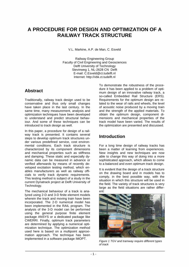
It is evident that the design of a track structureon the drawing board and in models has tocomply, in the best possible way, with thesituation in which this structure will be used inthe field. The variety of track structures is verylarge as the field situations are rather differ-ent:
Figure 1 TGV and tramway require different typesof track
- 2 -
• Different axle loads• Different operating speeds• Curved and straight lines• Urban and rural areas• Tracks in transitions• Tracks in level crossings• Tracks on bridges, in tunnels or in another
way integrated in major engineeringstructures
• Tracks on specific types of soil
The number of types of track structures whichare used nowadays, is mainly reduced forreasons of:
• constructability• maintainability• reliability
This deals with the fact that standardization intrack design and track works reduces costsand possible mistakes. Moreover tracks aregenerally designed and built with a large re-serve in order to avoid a possible failure dur-ing operation, or to meet new operationalneeds in the future. Most track structures,however, are still based on experiences andempirical relations instead of a fundamentalstudy of track behaviour using numericalsimulation and optimization techniques.
Track design
One way to perform a study focussing on thetrack behaviour is outlined below, first in the-ory and later by means of an example. Firsttwo steps in studying the behaviour areschematizing the structure and collecting thenecessary parameter data from field or labo-ratory experiments. These two steps areclosely related as schematized structurescannot contain more than the available data,while in some of the advanced schematizedstructures only a part of the available data willbe used.
In order to reduce the complexity of the trackdesign, only the vertical behaviour in straighttrack is considered in the numerical model.Another assumption is linear elastic behaviourof the applied materials. To perform a fulltrack simulation (which will be discussed inthe one-but-next section) the following data isneeded:
• The vertical track stiffness, comprisingstiffnesses of all flexible components likerailpads, elastic compounds, ballast, etc.expressed in:• (Quasi-) static values• Dynamic values• Load-dependent values
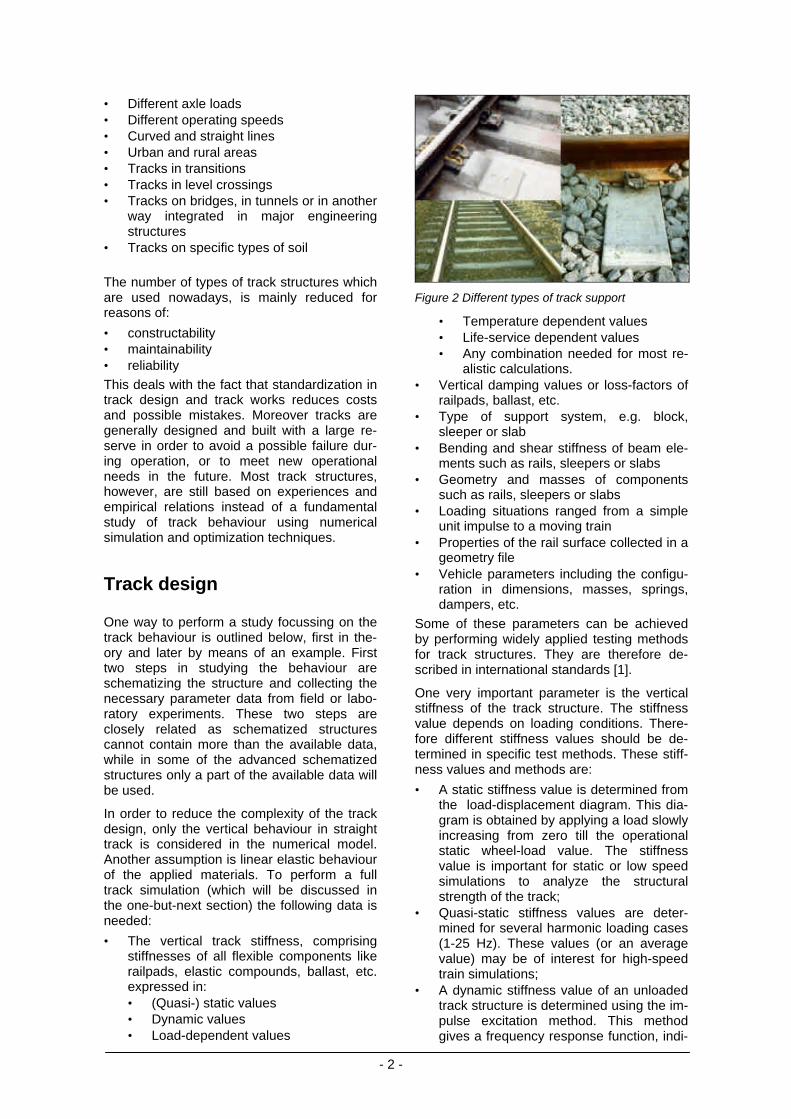
Figure 2 Different types of track support
• Temperature dependent values• Life-service dependent values• Any combination needed for most re-
alistic calculations.• Vertical damping values or loss-factors of
railpads, ballast, etc.• Type of support system, e.g. block,
sleeper or slab• Bending and shear stiffness of beam ele-
ments such as rails, sleepers or slabs• Geometry and masses of components
such as rails, sleepers or slabs• Loading situations ranged from a simple
unit impulse to a moving train• Properties of the rail surface collected in a
geometry file• Vehicle parameters including the configu-
ration in dimensions, masses, springs,dampers, etc.
Some of these parameters can be achievedby performing widely applied testing methodsfor track structures. They are therefore de-scribed in international standards [1].
One very important parameter is the verticalstiffness of the track structure. The stiffnessvalue depends on loading conditions. There-fore different stiffness values should be de-termined in specific test methods. These stiff-ness values and methods are:
• A static stiffness value is determined fromthe load-displacement diagram. This dia-gram is obtained by applying a load slowlyincreasing from zero till the operationalstatic wheel-load value. The stiffnessvalue is important for static or low speedsimulations to analyze the structuralstrength of the track;
• Quasi-static stiffness values are deter-mined for several harmonic loading cases(1-25 Hz). These values (or an averagevalue) may be of interest for high-speedtrain simulations;
• A dynamic stiffness value of an unloadedtrack structure is determined using the im-pulse excitation method. This methodgives a frequency response function, indi-
- 3 -
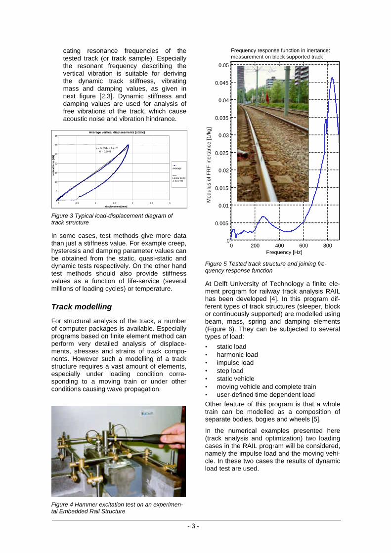
cating resonance frequencies of thetested track (or track sample). Especiallythe resonant frequency describing thevertical vibration is suitable for derivingthe dynamic track stiffness, vibratingmass and damping values, as given innext figure [2,3]. Dynamic stiffness anddamping values are used for analysis offree vibrations of the track, which causeacoustic noise and vibration hindrance.
Average vertical displacements (static)
y = 14.854x + 0.4151R2 = 0.9948
0
5
10
15
20
25
30
35
0 0.5 1 1.5 2 2.5 3displacement [mm]
vert
ical
fo
rce
[kN
]
average
Linear trend2-30.0 kN
Figure 3 Typical load-displacement diagram oftrack structure
In some cases, test methods give more datathan just a stiffness value. For example creep,hysteresis and damping parameter values canbe obtained from the static, quasi-static anddynamic tests respectively. On the other handtest methods should also provide stiffnessvalues as a function of life-service (severalmillions of loading cycles) or temperature.
Track modelling
For structural analysis of the track, a numberof computer packages is available. Especiallyprograms based on finite element method canperform very detailed analysis of displace-ments, stresses and strains of track compo-nents. However such a modelling of a trackstructure requires a vast amount of elements,especially under loading condition corre-sponding to a moving train or under otherconditions causing wave propagation.
Figure 4 Hammer excitation test on an experimen-tal Embedded Rail Structure
0 200 400 600 8000
0.005
0.01
0.015
0.02
0.025
0.03
0.035
0.04
0.045
0.05
Frequency [Hz]
Mod
ulus
of F
RF
iner
tanc
e [1
/kg]
Frequency response function in inertance:measurement on block supported track
Figure 5 Tested track structure and joining fre-quency response function
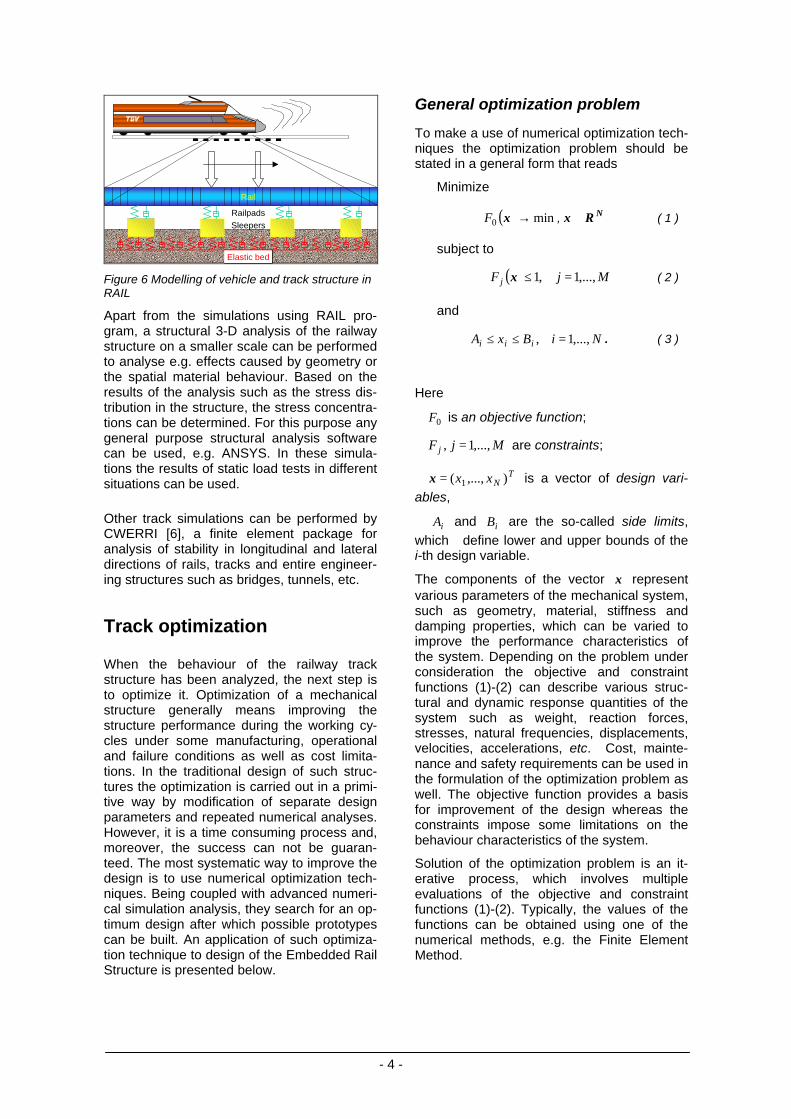
At Delft University of Technology a finite ele-ment program for railway track analysis RAILhas been developed [4]. In this program dif-ferent types of track structures (sleeper, blockor continuously supported) are modelled usingbeam, mass, spring and damping elements(Figure 6). They can be subjected to severaltypes of load:
• static load• harmonic load• impulse load• step load• static vehicle• moving vehicle and complete train• user-defined time dependent load
Other feature of this program is that a wholetrain can be modelled as a composition ofseparate bodies, bogies and wheels [5].
In the numerical examples presented here(track analysis and optimization) two loadingcases in the RAIL program will be considered,namely the impulse load and the moving vehi-cle. In these two cases the results of dynamicload test are used.
- 4 -
RailpadsSleepers
Elastic bed
Rail
Figure 6 Modelling of vehicle and track structure inRAIL
Apart from the simulations using RAIL pro-gram, a structural 3-D analysis of the railwaystructure on a smaller scale can be performedto analyse e.g. effects caused by geometry orthe spatial material behaviour. Based on theresults of the analysis such as the stress dis-tribution in the structure, the stress concentra-tions can be determined. For this purpose anygeneral purpose structural analysis softwarecan be used, e.g. ANSYS. In these simula-tions the results of static load tests in differentsituations can be used.
Other track simulations can be performed byCWERRI [6], a finite element package foranalysis of stability in longitudinal and lateraldirections of rails, tracks and entire engineer-ing structures such as bridges, tunnels, etc.
Track optimization
When the behaviour of the railway trackstructure has been analyzed, the next step isto optimize it. Optimization of a mechanicalstructure generally means improving thestructure performance during the working cy-cles under some manufacturing, operationaland failure conditions as well as cost limita-tions. In the traditional design of such struc-tures the optimization is carried out in a primi-tive way by modification of separate designparameters and repeated numerical analyses.However, it is a time consuming process and,moreover, the success can not be guaran-teed. The most systematic way to improve thedesign is to use numerical optimization tech-niques. Being coupled with advanced numeri-cal simulation analysis, they search for an op-timum design after which possible prototypescan be built. An application of such optimiza-tion technique to design of the Embedded RailStructure is presented below.
General optimization problem
To make a use of numerical optimization tech-niques the optimization problem should bestated in a general form that reads
Minimize
( ) min0 →xF , NRx ∈ ( 1 )
subject to
( ) MjF j ,...,1,1 =≤x ( 2 )
and
NiBxA iii ,...,1, =≤≤ . ( 3 )
Here
0F is an objective function;
MjF j ,...,1, = are constraints;
TNxx ),...,( 1=x is a vector of design vari-
ables,
iA and iB are the so-called side limits,which define lower and upper bounds of thei-th design variable.
The components of the vector x representvarious parameters of the mechanical system,such as geometry, material, stiffness anddamping properties, which can be varied toimprove the performance characteristics ofthe system. Depending on the problem underconsideration the objective and constraintfunctions (1)-(2) can describe various struc-tural and dynamic response quantities of thesystem such as weight, reaction forces,stresses, natural frequencies, displacements,velocities, accelerations, etc. Cost, mainte-nance and safety requirements can be used inthe formulation of the optimization problem aswell. The objective function provides a basisfor improvement of the design whereas theconstraints impose some limitations on thebehaviour characteristics of the system.
Solution of the optimization problem is an it-erative process, which involves multipleevaluations of the objective and constraintfunctions (1)-(2). Typically, the values of thefunctions can be obtained using one of thenumerical methods, e.g. the Finite ElementMethod.
- 5 -
Approximation concept
The optimization problem (1)-(3) can besolved using a conventional method ofmathematical programming. However, forsystems with many degrees of freedom the fi-nite element analysis can be time consuming.As a result, the total computational effort ofthe optimization might become prohibitive.This difficulty has been mitigated in the mid-seventies by introducing approximation con-cepts [7].
According to the approximation concepts theoriginal functions (1)-(2) are replaced with ap-proximate ones which are computationallyless time consuming. Instead of the originaloptimization problem (1)-(3) a succession ofsimpler approximated subproblems similar tothe original one formulated using the ap-proximation functions is to be solved. Eachsimplified problem then has the followingform:
Minimize
( ) min~
0 →xkF , NRx ∈ ( 4 )
subject to
( ) MjF kj ,...,1,1
~=≤x ( 5 )
and
NiBBAABxA ikii
ki
kii
ki ,...,1,,, =≤≥≤≤ , ( 6 )
where the superscript k is the number of theiteration step, F
~ is the approximation of the
original function F , kiA and k
iB are move lim-its defining the range of applicability of theapproximations.
Since the functions (4)-(5) are chosen to besimple and computationally inexpensive, anyconventional method of optimization [7] canbe used to solve the problem (4)-(6). The so-lution of the problem k
*x is then chosen asstarting point for the (k+1)-th step and the op-timization problem (4)-(6) re-formulated withnew approximation functions
( ) ),...,0(,1~ 1 MjF k
j =≤+ x and move limits
1+kiA and 1+k
iB is to be solved. The processis repeated until the convergence criteria aresatisfied.
Multipoint approximation method
The approximation is defined as a function ofthe design variables x and tuning parameters
a (for brevity the indices k and j will be omit-ted). To determine the components of vector athe following weighted least-squares minimi-zation problem is to be solved [8]:
Find vector a that minimizes
∑=
−=P
ppp FFwG
1
2)0( })],(~
)([{)( axxa p ( 7 )
Here )( pxF is the value of the original func-
tion from (1)-(2) evaluated at the point of thedesign parameters space px , and P is the
total number of such points; )0(pw is a weight
factor that characterises the relative contribu-tion of the information about the original func-tion at the point px . For the numerical exam-
ples the multiplicative form of the approxi-mating function has been chosen, which hasthe form
∏=
=P
i
ai
ixaF1
0 )()(~
x ( 8 )
The optimization process is controlled bychanging the move limits in each iterationstep. The main rules of the strategy ofchanging of the move limits employed in themethod are:
• if the approximating functions do not ade-quately represent the original ones in thecurrent optimum point, what means thatthe search subregion is larger than therange of applicability of the current ap-proximations, the move limits (6) arechanged to reduce the size of the searchsubregion;
• if the approximations are good and thesolution of the optimization problem (4)-(6) is an internal point of the searchsubregion it could be considered as thesolution of the original optimization prob-lem (1)-(3), the search subregion is re-duced;
• if the current optimum point belongs to theboundary of the search subregion (one ofthe move limits is active) whereas the ap-proximations are good the size of thesubregion is not changed on the next it-eration.
The iteration process is terminated if the ap-proximations are good, none of the move lim-its is active and the search subregion is smallenough. More details about the weight coeffi-cients assignment, the move limits strategyand the most recent developments of themethod can be found in [9].
- 6 -
Objectives for track optimization
Formulating the objectives for optimized trackstructures requires first a keen considerationon which response quantities characterize theperformance of track structures. The followingobjectives which are considered to be impor-tant, have been selected for optimization:
Objective 1. Based on the frequency responsefunction (FRF), resonant frequencies ofthe track structure should coincide neitherwith vehicle resonant frequencies, norwith other structural resonant frequencies.Amplification at these frequencies shouldbe restricted [10]. These conditions leadto better riding characteristics of the vehi-cle and less effort on maintenance oftracks, vehicles and structures.
Objective 2. The acoustic characteristics ofthe track structure can be estimated by aspecific response quantity, a so-calledattenuation rate (distance damping). Theattenuation rate characterizes the abilityof a track structure to damp the vibrationson different distances from the source.Acoustic noise radiating from the rails de-creases as the attenuation rates increase.And this is favourable for the direct envi-ronment of railway lines.
Objective 3. Wheel-rail contact forces shouldbe below prescribed values in order to re-duce rail and wheel wear. These forcesstrongly depend on the rail surface ge-ometry. The standard deviation of theseforces should be lower than e.g. 20% ofthe static wheel-rail contact force [11].This percentage is based on simulationswith a moving vehicle on an averagequality rail surface geometry for a suffi-cient time period.
Apart from the above mentioned objectives,other could be formulated and taken into ac-count during optimization.
Example
In this Section the proposed approach isdemonstrated by applying it to the design andoptimization of a specific slabtrack system, aso-called Embedded Rail Structure (ERS).Netherlands Railways has applied this systemsince the 60's on engineering structures(bridges) and since the early 70's in concreteslabs as well as in level crossings. Later, ERShas found its way to other companies, includ-ing tramway and metro, all over the world.
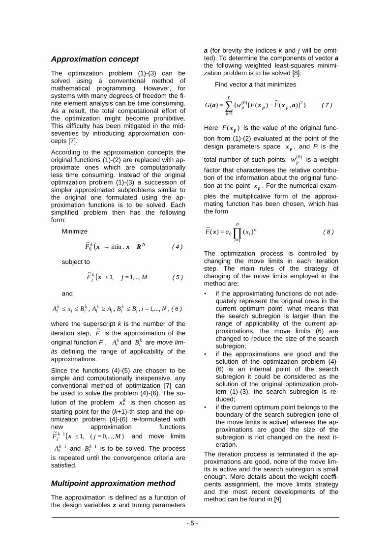
Figure 7 Embedded Rail Structure installation nearBest (the Netherlands)
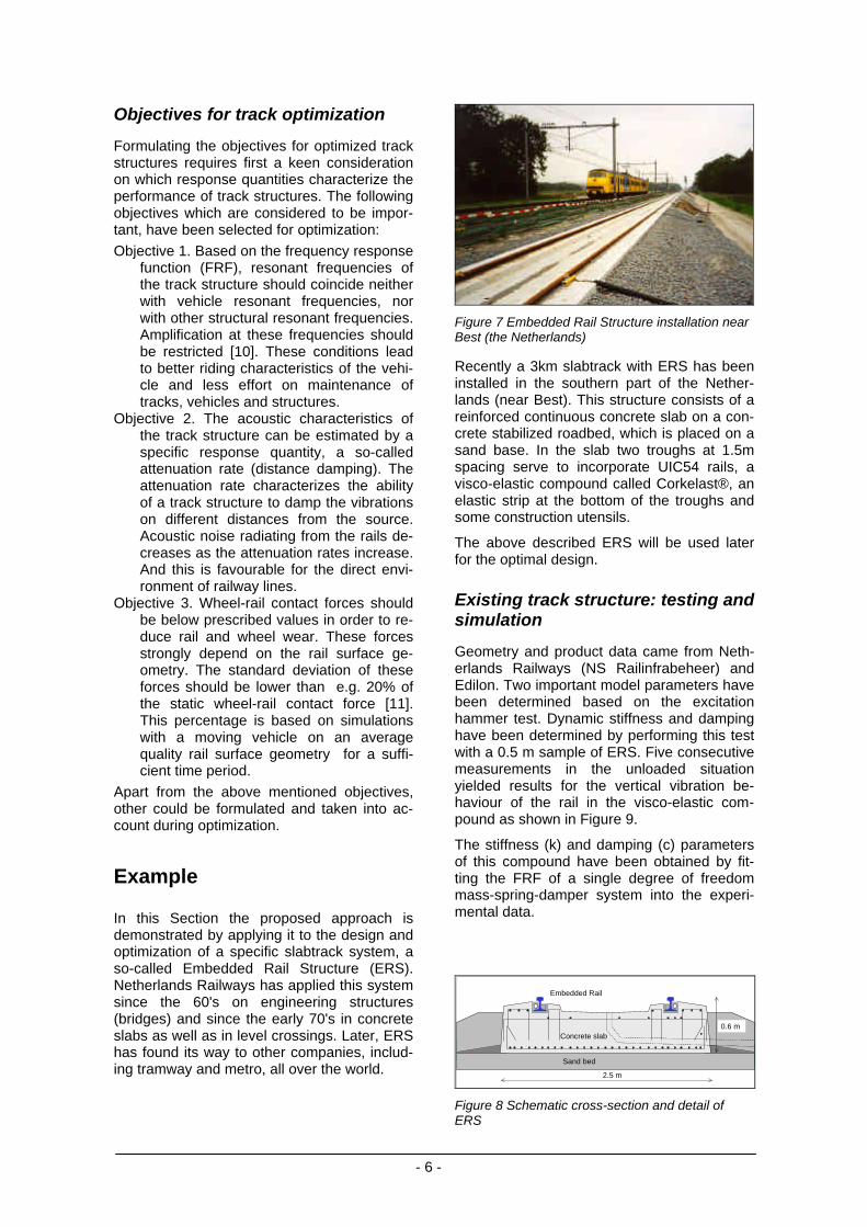
Recently a 3km slabtrack with ERS has beeninstalled in the southern part of the Nether-lands (near Best). This structure consists of areinforced continuous concrete slab on a con-crete stabilized roadbed, which is placed on asand base. In the slab two troughs at 1.5mspacing serve to incorporate UIC54 rails, avisco-elastic compound called Corkelast®, anelastic strip at the bottom of the troughs andsome construction utensils.
The above described ERS will be used laterfor the optimal design.
Existing track structure: testing andsimulation
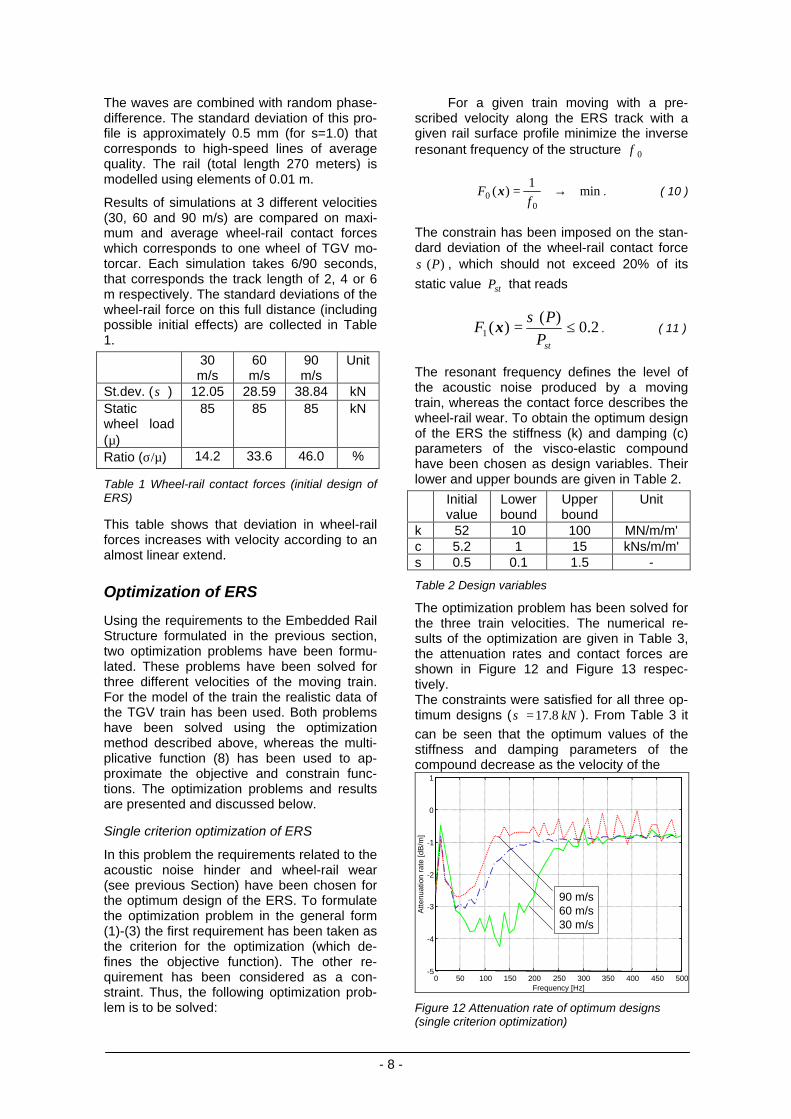
Geometry and product data came from Neth-erlands Railways (NS Railinfrabeheer) andEdilon. Two important model parameters havebeen determined based on the excitationhammer test. Dynamic stiffness and dampinghave been determined by performing this testwith a 0.5 m sample of ERS. Five consecutivemeasurements in the unloaded situationyielded results for the vertical vibration be-haviour of the rail in the visco-elastic com-pound as shown in Figure 9.
The stiffness (k) and damping (c) parametersof this compound have been obtained by fit-ting the FRF of a single degree of freedommass-spring-damper system into the experi-mental data.
Sand bed
Concrete slab
Embedded Rail
2.5 m
0.6 m
Figure 8 Schematic cross-section and detail ofERS
- 7 -
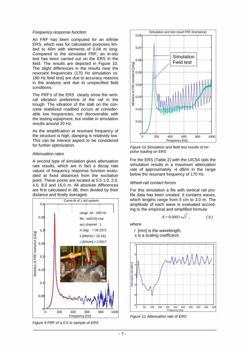
Frequency response function
An FRF has been computed for an infiniteERS, which was for calculation purposes lim-ited to 40m with elements of 0.04 m long.Compared to the simulated FRF, an in-situtest has been carried out on the ERS in thefield. The results are depicted in Figure 10.The slight differences in the results near theresonant frequencies (170 Hz simulation vs.160 Hz field test) are due to accuracy reasonsin the analysis and due to unspecified fieldconditions.
The FRF's of the ERS clearly show the verti-cal vibration preference of the rail in thetrough. The vibration of the slab on the con-crete stabilized roadbed occurs at consider-able low frequencies, not discoverable withthe testing equipment, but visible in simulationresults around 20 Hz.
As the amplification at resonant frequency ofthe structure is high, damping is relatively low.This can be interest aspect to be consideredfor further optimization.
Attenuation rates
A second type of simulation gives attenuationrate results, which are in fact a decay ratevalues of frequency response function evalu-ated at fixed distances from the excitationpoint. These points are located at 0.5 1.0, 2.0,4.0, 8.0 and 16.0 m. All absolute differencesare first calculated in dB, then divided by theirdistance and finally averaged.
Frequency [Hz]0 200 400 600 800 1000
0
0.05
0.1
0.15
0.2
0.25
0.3
0.35
0.4Curve-fit of 1 dof system
Mod
ulus
of F
RF
iner
tanc
e [1
/kg]
range: 50 - 500 Hz
file : ed411b.mat
acc.channel : 1
m [kg] = 30.2372
k [MN/m] = 26.161
c [kNs/m] = 2.5617
Figure 9 FRF of a 0.5 m sample of ERS
0 200 400 600 800 10000
0.01
0.02
0.03
0.04
0.05
0.06
0.07
0.08Simulation and test result FRF (Inertance)
Frequency [Hz]
Mod
ulus
of F
RF
iner
tanc
e [1
/kg]
SimulationField test
Figure 10 Simulation and field test results of im-pulse loading on ERS
For the ERS (Table 2) with the UIC54 rails thesimulation results in a maximum attenuationrate of approximately -4 dB/m in the rangebelow the resonant frequency of 170 Hz.
Wheel-rail contact forces
For this simulation a file with vertical rail pro-file data has been created. It contains waves,which lengths range from 5 cm to 3.0 m. Theamplitude of each wave is evaluated accord-ing to the empirical and simplified formula:
λsA 0001.0= , ( 9 )
where
λ [mm] is the wavelength; s is a scaling coefficient.
0 50 100 150 200 250 300 350 400 450 500-5
-4
-3
-2
-1
0
1
Frequency [Hz]
Atte
nuat
ion
rate
[dB
/m]
Figure 11 Attenuation rate of ERS
- 8 -
The waves are combined with random phase-difference. The standard deviation of this pro-file is approximately 0.5 mm (for s=1.0) thatcorresponds to high-speed lines of averagequality. The rail (total length 270 meters) ismodelled using elements of 0.01 m.
Results of simulations at 3 different velocities(30, 60 and 90 m/s) are compared on maxi-mum and average wheel-rail contact forceswhich corresponds to one wheel of TGV mo-torcar. Each simulation takes 6/90 seconds,that corresponds the track length of 2, 4 or 6m respectively. The standard deviations of thewheel-rail force on this full distance (includingpossible initial effects) are collected in Table1.
30m/s
60m/s
90m/s
Unit
St.dev. (σ ) 12.05 28.59 38.84 kNStaticwheel load(µ)
85 85 85 kN
Ratio (σ/µ) 14.2 33.6 46.0 %
Table 1 Wheel-rail contact forces (initial design ofERS)
This table shows that deviation in wheel-railforces increases with velocity according to analmost linear extend.
Optimization of ERS
Using the requirements to the Embedded RailStructure formulated in the previous section,two optimization problems have been formu-lated. These problems have been solved forthree different velocities of the moving train.For the model of the train the realistic data ofthe TGV train has been used. Both problemshave been solved using the optimizationmethod described above, whereas the multi-plicative function (8) has been used to ap-proximate the objective and constrain func-tions. The optimization problems and resultsare presented and discussed below.
Single criterion optimization of ERS
In this problem the requirements related to theacoustic noise hinder and wheel-rail wear(see previous Section) have been chosen forthe optimum design of the ERS. To formulatethe optimization problem in the general form(1)-(3) the first requirement has been taken asthe criterion for the optimization (which de-fines the objective function). The other re-quirement has been considered as a con-straint. Thus, the following optimization prob-lem is to be solved:
For a given train moving with a pre-scribed velocity along the ERS track with agiven rail surface profile minimize the inverseresonant frequency of the structure 0f
min1
)(0
0 →=f
F x . ( 10 )
The constrain has been imposed on the stan-dard deviation of the wheel-rail contact force
)(Pσ , which should not exceed 20% of its
static value stP that reads
2.0)(
)(1 ≤=stP
PF
σx . ( 11 )
The resonant frequency defines the level ofthe acoustic noise produced by a movingtrain, whereas the contact force describes thewheel-rail wear. To obtain the optimum designof the ERS the stiffness (k) and damping (c)parameters of the visco-elastic compoundhave been chosen as design variables. Theirlower and upper bounds are given in Table 2.
Initialvalue
Lowerbound
Upperbound
Unit
k 52 10 100 MN/m/m'c 5.2 1 15 kNs/m/m's 0.5 0.1 1.5 -
Table 2 Design variables
The optimization problem has been solved forthe three train velocities. The numerical re-sults of the optimization are given in Table 3,the attenuation rates and contact forces areshown in Figure 12 and Figure 13 respec-tively.The constraints were satisfied for all three op-timum designs ( kN8.17=σ ). From Table 3 it
can be seen that the optimum values of thestiffness and damping parameters of thecompound decrease as the velocity of the
0 50 100 150 200 250 300 350 400 450 500-5
-4
-3
-2
-1
0
1
Frequency [Hz]
Atte
nuat
ion
rate
[dB
/m]
90 m/s60 m/s30 m/s
Figure 12 Attenuation rate of optimum designs(single criterion optimization)
- 9 -
0 0.01 0.02 0.03 0.04 0.05 0.06 0.0720
40
60
80
100
120
140
160Wheel/rail contact forces
Time [s]
For
ce [k
N]
90 m/s60 m/s30 m/s
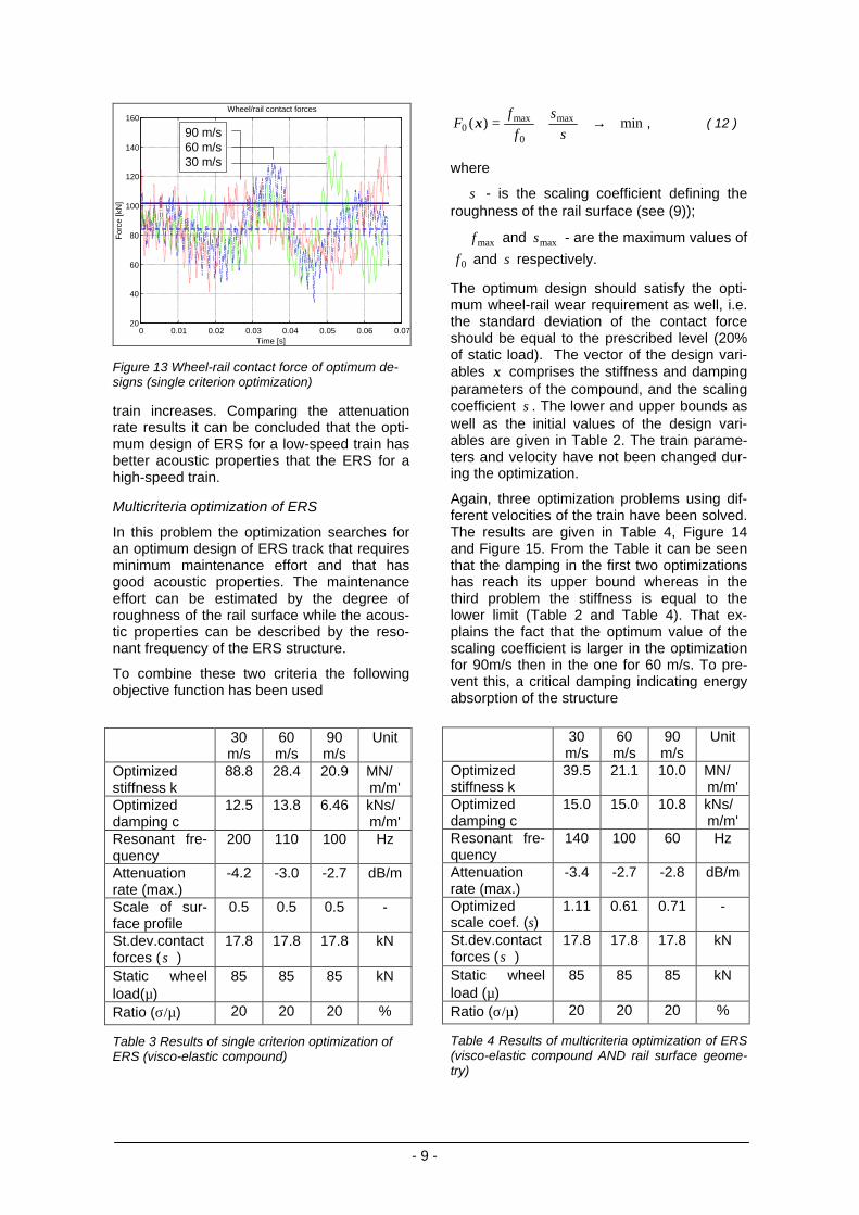
Figure 13 Wheel-rail contact force of optimum de-signs (single criterion optimization)
train increases. Comparing the attenuationrate results it can be concluded that the opti-mum design of ERS for a low-speed train hasbetter acoustic properties that the ERS for ahigh-speed train.
Multicriteria optimization of ERS
In this problem the optimization searches foran optimum design of ERS track that requiresminimum maintenance effort and that hasgood acoustic properties. The maintenanceeffort can be estimated by the degree ofroughness of the rail surface while the acous-tic properties can be described by the reso-nant frequency of the ERS structure.
To combine these two criteria the followingobjective function has been used
30m/s
60m/s
90m/s
Unit
Optimizedstiffness k
88.8 28.4 20.9 MN/m/m'
Optimizeddamping c
12.5 13.8 6.46 kNs/m/m'
Resonant fre-quency
200 110 100 Hz
Attenuationrate (max.)
-4.2 -3.0 -2.7 dB/m
Scale of sur-face profile
0.5 0.5 0.5 -
St.dev.contactforces (σ )
17.8 17.8 17.8 kN
Static wheelload(µ)
85 85 85 kN
Ratio (σ/µ) 20 20 20 %
Table 3 Results of single criterion optimization ofERS (visco-elastic compound)
min)( max
0
max0 →+=
s
s
f
fF x , ( 12 )
where
s - is the scaling coefficient defining theroughness of the rail surface (see (9));
maxf and maxs - are the maximum values of
0f and s respectively.
The optimum design should satisfy the opti-mum wheel-rail wear requirement as well, i.e.the standard deviation of the contact forceshould be equal to the prescribed level (20%of static load). The vector of the design vari-ables x comprises the stiffness and dampingparameters of the compound, and the scalingcoefficient s . The lower and upper bounds aswell as the initial values of the design vari-ables are given in Table 2. The train parame-ters and velocity have not been changed dur-ing the optimization.
Again, three optimization problems using dif-ferent velocities of the train have been solved.The results are given in Table 4, Figure 14and Figure 15. From the Table it can be seenthat the damping in the first two optimizationshas reach its upper bound whereas in thethird problem the stiffness is equal to thelower limit (Table 2 and Table 4). That ex-plains the fact that the optimum value of thescaling coefficient is larger in the optimizationfor 90m/s then in the one for 60 m/s. To pre-vent this, a critical damping indicating energyabsorption of the structure
30m/s
60m/s
90m/s
Unit
Optimizedstiffness k
39.5 21.1 10.0 MN/m/m'
Optimizeddamping c
15.0 15.0 10.8 kNs/m/m'
Resonant fre-quency
140 100 60 Hz
Attenuationrate (max.)
-3.4 -2.7 -2.8 dB/m
Optimizedscale coef. (s)
1.11 0.61 0.71 -
St.dev.contactforces (σ )
17.8 17.8 17.8 kN
Static wheelload (µ)
85 85 85 kN
Ratio (σ/µ) 20 20 20 %
Table 4 Results of multicriteria optimization of ERS(visco-elastic compound AND rail surface geome-try)
- 10 -
0 50 100 150 200 250 300 350 400 450 500-5
-4
-3
-2
-1
0
1
Frequency [Hz]
Atte
nuat
ion
rate
[dB
/m]
90 m/s60 m/s30 m/s
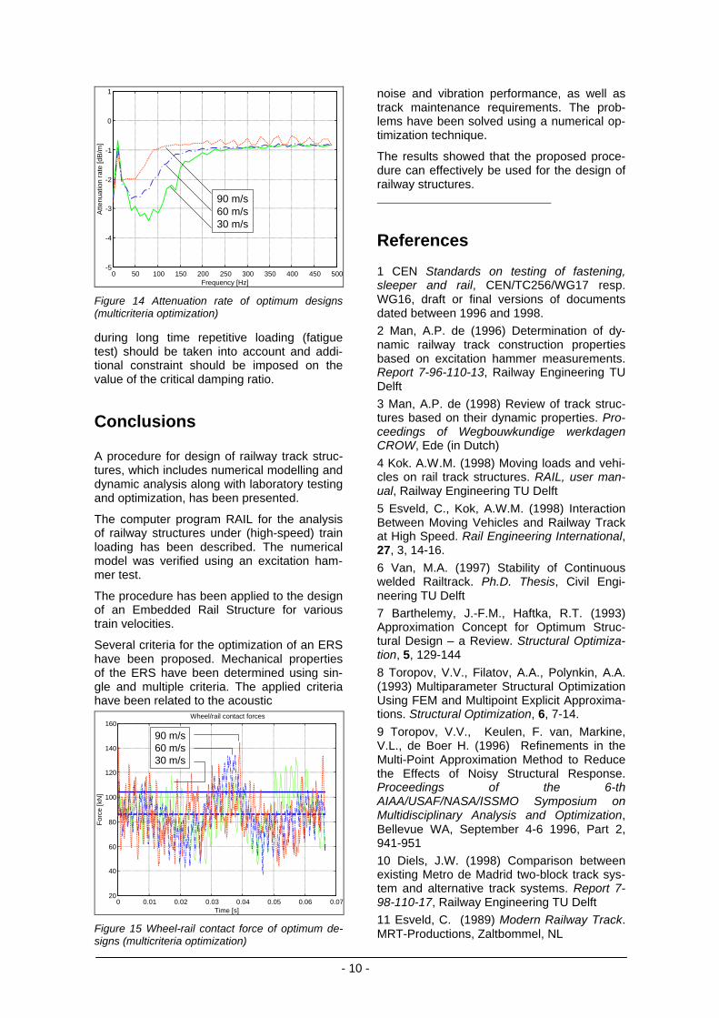
Figure 14 Attenuation rate of optimum designs(multicriteria optimization)
during long time repetitive loading (fatiguetest) should be taken into account and addi-tional constraint should be imposed on thevalue of the critical damping ratio.
Conclusions
A procedure for design of railway track struc-tures, which includes numerical modelling anddynamic analysis along with laboratory testingand optimization, has been presented.
The computer program RAIL for the analysisof railway structures under (high-speed) trainloading has been described. The numericalmodel was verified using an excitation ham-mer test.
The procedure has been applied to the designof an Embedded Rail Structure for varioustrain velocities.
Several criteria for the optimization of an ERShave been proposed. Mechanical propertiesof the ERS have been determined using sin-gle and multiple criteria. The applied criteriahave been related to the acoustic
0 0.01 0.02 0.03 0.04 0.05 0.06 0.0720
40
60
80
100
120
140
160Wheel/rail contact forces
Time [s]
For
ce [k
N]
90 m/s60 m/s30 m/s
Figure 15 Wheel-rail contact force of optimum de-signs (multicriteria optimization)
noise and vibration performance, as well astrack maintenance requirements. The prob-lems have been solved using a numerical op-timization technique.
The results showed that the proposed proce-dure can effectively be used for the design ofrailway structures.
References
1 CEN Standards on testing of fastening,sleeper and rail, CEN/TC256/WG17 resp.WG16, draft or final versions of documentsdated between 1996 and 1998.
2 Man, A.P. de (1996) Determination of dy-namic railway track construction propertiesbased on excitation hammer measurements.Report 7-96-110-13, Railway Engineering TUDelft
3 Man, A.P. de (1998) Review of track struc-tures based on their dynamic properties. Pro-ceedings of Wegbouwkundige werkdagenCROW, Ede (in Dutch)
4 Kok. A.W.M. (1998) Moving loads and vehi-cles on rail track structures. RAIL, user man-ual, Railway Engineering TU Delft
5 Esveld, C., Kok, A.W.M. (1998) InteractionBetween Moving Vehicles and Railway Trackat High Speed. Rail Engineering International,27, 3, 14-16.
6 Van, M.A. (1997) Stability of Continuouswelded Railtrack. Ph.D. Thesis, Civil Engi-neering TU Delft
7 Barthelemy, J.-F.M., Haftka, R.T. (1993)Approximation Concept for Optimum Struc-tural Design – a Review. Structural Optimiza-tion, 5, 129-144
8 Toropov, V.V., Filatov, A.A., Polynkin, A.A.(1993) Multiparameter Structural OptimizationUsing FEM and Multipoint Explicit Approxima-tions. Structural Optimization, 6, 7-14.
9 Toropov, V.V., Keulen, F. van, Markine,V.L., de Boer H. (1996) Refinements in theMulti-Point Approximation Method to Reducethe Effects of Noisy Structural Response.Proceedings of the 6-thAIAA/USAF/NASA/ISSMO Symposium onMultidisciplinary Analysis and Optimization,Bellevue WA, September 4-6 1996, Part 2,941-951
10 Diels, J.W. (1998) Comparison betweenexisting Metro de Madrid two-block track sys-tem and alternative track systems. Report 7-98-110-17, Railway Engineering TU Delft
11 Esveld, C. (1989) Modern Railway Track.MRT-Productions, Zaltbommel, NL