A Process Splitting Transformation for Kahn Process Networks Sjoerd Meijer.

A Platform-based Design Flow for Kahn ProcessNetworks
Abhijit DavareQi ZhuAlberto L. Sangiovanni-Vincentelli
Electrical Engineering and Computer SciencesUniversity of California at Berkeley
Technical Report No. UCB/EECS-2006-30
http://www.eecs.berkeley.edu/Pubs/TechRpts/2006/EECS-2006-30.html
March 28, 2006

Copyright © 2006, by the author(s).All rights reserved.
Permission to make digital or hard copies of all or part of this work forpersonal or classroom use is granted without fee provided that copies arenot made or distributed for profit or commercial advantage and that copiesbear this notice and the full citation on the first page. To copy otherwise, torepublish, to post on servers or to redistribute to lists, requires prior specificpermission.
Acknowledgement
Thanks to Professor Edward Lee for his guidance. His extensiveknowledge of the formalisms underlying meta-modeling techniques hasgreatly impacted this work. Many thanks to the members of the Metropolisteam. In particular, thanks to Yosinori Watanabe, Alex Kondratyev, AlviseBonivento, Trevor Meyerowitz, and Douglas Densmore. Also thanks to theanonymous reviewers from the Fall 2004 offering of EE 290N for theircomments, especially for the first step of the design flow.

A Platform-based Design Flowfor Kahn Process Networks
Abhijit Davare, Qi Zhu, Alberto Sangiovanni-Vincentelli
Abstract
Effectively implementing multimedia applications on multiprocessor architectures is a keychallenge in system-level design. This work explores automated solutions to this problem byconsidering two separate directions of research. First, the problem is placed within the contextof a generalized mapping strategy and the concept of a common semantic domain is developedwhich is capable of reasoning about the automation techniques that are to be applied. Second,a specialized design flow and associated algorithms are developed to solve this problem.
The idea of a common semantic domain is described and its usefulness in other mappingproblems is demonstrated. For this particular problem, a common semantic domain is identi-fied and forms the basis of the algorithms which are developed in the design flow.
The design flow is divided into four clearly defined steps, to ensure the tractability ofoptimization problems while obtaining a good overall solution. The separation of the flowinto these steps allows prior work from a variety of sources to be used. Efficient heuristicsare developed for each step of the design flow. The effectiveness of the heuristics used in thisdesign flow is demonstrated by applying them to an industrial case study.
1 Introduction
To enable effective design reuse at the system level, separating the functional and architecturalaspects of a design is essential. To realize an implementation, the functional specification is cap-tured and then mapped onto a particular architectural platform. The mapping step must ensure thatthe association between the two designs is legal and can be realized. Also, mapping must try tomaximize system performance according to the desired metrics. This process is depicted in Fig-ure 1, where a functional algorithm and an architectural platform are captured as models and thenmapped together to produce a system implementation. If necessary, the functional or architecturalmodels may need to modified if a suitable solution cannot be found – this is represented by thedotted arrows. The overall objective is obtain a suitable solution as quickly as possible withoutmany iterations.
The task of mapping is to choose a suitable association between the functional and architec-tural designs from the set of all possible associations. Traditionally, this task has been carried outmanually through designer intuition. While manual mapping may produce good results, there are
1

Figure 1: Overview of Mapping in System-Level Design
many challenges to face. Today, increasing design complexity and heterogeneity mean that the sizeof this design space is increasing. In order to shorten design time, automation is necessary. Thebroad focus of the research presented here is exactly this task of automated mapping. In this work,we will focus on a specific problem within the realm of automated mapping – that of efficientlyimplementing multimedia applications on heterogeneous multiprocessor architectures. This prob-lem is pertinent for a whole host of systems, ranging from cellular phones, digital cameras, andportable audio players to high-end printers and broadcast video units.
The chief characteristic of multimedia applications is that they involve sets of transformationsto streams of data. Data streams in these applications can represent any type of information, suchas audio samples, image blocks or video frames. Typically, the streams have one source and onesink, and must be non-lossy. Usually, reordering of data items in streams is not acceptable. Thetransformations that are carried out on data streams can be quite complex and their granularityis design-dependent. These transformations may consume data from any number of streams andproduce data to any number of streams.
Heterogeneous multiprocessor architectures are becoming common as power and nanometer-era challenges force designers to use several specialized cores instead of relying on a monolithicprocessor. The potential benefits of these architectures include increased throughput and lowerpower consumption. However, the relative novelty of these types of architectures along with theirhighly concurrent nature introduces many challenges. The paradigm of software developmenttoday is still based on sequential code, meaning that it is often difficult to implement algorithmson these types of architectures. This difficulty often precludes design space exploration, since thecost of evaluation is too high.
The platform-based design methodology [27] attempts to remedy some of these problems,by advocating a meet-in-the-middle approach to design, instead of a purely bottom-up or top-down view. In this methodology, an abstract model of the actual architectural platform is typicallyconstructed which provides a set of services. The functional application is refined such that itmakes use of the services. Different associations between the functional and architectural modelreflect different points in the design space. Once an attractive point has been found, then the system
2
can be implemented using either automatic or manual approaches.
Within this methodology, finding the convenient representations for the architectural and func-tional models and finding a suitable point in the design space remain difficult problems. This workattempts to address both of these issues.
1.1 Contributions
The philosophy of the approach to automated mapping developed in this work is based on theconcept of a Common Semantic Domain (CSD). Intuitively, a common semantic domain enablesreasoning about the aspects of the behavior of the functional and architectural models. The hy-pothesis is that the concept of CSD is important in the development of the efficient mapping andallocation algorithms for system-level design problems. A contribution of this work is the ini-tial description of the CSD concept along with a concrete definition of a CSD for the multimediaapplications and heterogeneous multiprocessor architectures that we consider. In this CSD, boththe functional and architectural models are represented with the Kahn Process Networks model ofcomputation.
The major contribution of this research is the development of a design flow for Kahn ProcessNetwork specifications within the Platform-based methodology. This design flow is decomposedinto four well-defined steps – reconfiguration, allocation, initial sizing, and runtime deadlock de-tection & resolution. This decomposition enables us to focus on specific optimization problemsand leverage existing work for each step. A beneficial consequence of the separation of the de-sign flow into these steps is that the previous work that we consider comes from a number ofdifferent research communities. For each step in the design flow, we develop novel algorithms andheuristics.
The design flow is aligned with the principles of the Platform-based design methodology [27]and therefore promotes orthogonalization, analysis, and refinement. To validate this design flow,we have implemented and applied the algorithms to an industrial design example within the Met-ropolis [4] framework.
1.2 Organization
The remainder of this paper is organized as follows: In Section 2, background information isgiven on models of computation that are suitable for multimedia applications – including KahnProcess Networks(KPN). Also, some of the salient characteristics of heterogeneous multiprocessorarchitectural platforms and examples of these are presented. In Section 4, we describe in furtherdetail some of the system-level design environments that try to tackle the problem of implementingKPN specifications on heterogeneous multiprocessor platforms. In Section 3, an introduction isprovided to the Metropolis design framework. This framework supports the Platform-based designmethodology and has been used to validate the design flow described in this work. Section 5explains the concept of a Common Semantic Domain and how this applies to the problem ofautomated mapping in general and the design flow developed in this work. The four-step design
3
flow itself is described in Section 6 with approaches and algorithms described at each step. Thedesign flow is applied to an industrial case study in Section 7. Finally, conclusions and avenues forfuture work are presented in Sections 8 and 9.
2 Background
In this section, some background material for the task of mapping multimedia applications onheterogeneous multiprocessor architectures will be considered. In Section 2.1, models of compu-tation that are suitable for expressing the behavior of multimedia systems will be covered. Themotivation for focusing on the KPN model of computation will be provided as well. In Section2.2, further information will be provided on why heterogeneous multiprocessor architectures arerelevant for the topic at hand.
2.1 Models of Computation for Data-streaming systems
In this section, some of the models of computation that have been suggested for data-streamingsystems will be described in further detail. The expressiveness and suitability for analysis of thesemodels will be evaluated.
Kahn Process Networks [25] is a model of computation where concurrent processes communi-cate with each other through point-to-point one-way FIFOs. Read actions from these FIFOs blockuntil at least one data item (or token) becomes available. The FIFOs have unbounded size, so writeactions are non-blocking. Reads from the FIFOs are destructive, which means that a token canonly be read once.
More formally, each channel in a KPN is a signal which carries a finite (possibly empty) orinfinite sequence of tokens. The set of all possible signals is denotedS while the n-tuple of signalsis denoted asSn. The relationv is defined as the binary prefix relation on signals. For instance,s1 v s2 means that the sequence of tokens contained in the signals1 is a prefix of the sequence oftokens contained ins2. This definition generalizes to an element-wise prefix order, which can bedefined onSn. This element-wise prefix order is a CPO.
Any processP in the KPN with m inputs and n outputs is a mapping from its input signals to itsoutput signals,P : Sm → Sn. The semantics of KPN places a restriction on the type of mappingthat a process can represent. A process must be monotonic in its mapping from input signals tooutput signals under the element-wise prefix order,s1 v s2 ⇒ P (s1) v P (s2). This means thatsupplying additional inputs to a process results in additional outputs being produced, tokens whichhave already been produced cannot be retracted.
Under this restriction, and given the fact that the processes are monotonic functions on a CPO,the least fixpoint theorem tells us that a least fixpoint exists for a network of these processes.According to the denotational semantics of KPNs, this least fixpoint represents the behavior of theKPN [25]. This is the behavior that we want to find with simulation. However, the procedure forfinding this least fixpoint is not given under monotonicity conditions alone. To find this procedure,
4

we must apply a stronger condition on processes.
A stronger condition that is required is that of continuity, which requires that the result of thisfunction to an infinite input is the limit of its results to the finite approximations of this input.Under this stronger condition, a procedure for finding the least fixpoint behavior exists. This pro-cedure involves an initial condition of empty channels. Then, the processes are allowed to act onthe empty channels until no further change takes place. This is the procedure that we need forfinding the behavior of the KPN since it corresponds directly to simulation. To guarantee conti-nuity, the sufficient (but not necessary) condition imposed on Kahn processes involves blockingread semantics [26]. Since continuous functions are compositional, is suffices to ensure that eachprocess in a KPN is continuous to guarantee that the entire network has a deterministic behavior.
This is the appealing characteristic of the KPN model of computation – that execution is deter-ministic and independent of process interleaving. Also, this model of computation allows naturaldescription of applications since it places relatively few requirements on the designer other thanblocking reads.
Implementing KPN specifications on resource-constrained architectures has a key challenge:that of realizing a theoretically infinite-sized communication channel with a finite amount of ar-chitectural memory. Indeed, a KPN implemented in this manner no longer satisfies the originaldefinition of non-blocking writes, since a lack of storage space in the communication channel mayforce further write actions to be blocked. This additional constraint of blocking writes may pos-sibly introduce deadlock into the execution of the system. This undesirable occurrence is referredto asartificial deadlock [19]. It is undecidable in general to determine if a KPN can execute inbounded memory, therefore deadlocks cannot be avoided statically.
The resolution of artificial deadlock requires dynamically supplying extra storage to some com-munication channel which is involved in the deadlock. This is the basis of Parks’ algorithm [42].However, choosing the channel and the amount of memory to allocate such that the deadlock is re-solved with a minimum of extra memory is undecidable in general. A “bad” strategy will allocatememory to channels in such a way that the deadlock is not truly resolved, just postponed. In thiscase, the system will eventually run out of memory and the system will need to be reset.
Dataflow process networks are a special case of Kahn Process Networks where the executionof processes can be divided into a series of atomic firings [32]. This MoC in general suffers fromthe same undecidability as Kahn Process Networks [10]. In static dataflow [34], the number oftokens produced and consumed for each firing is statically fixed. Due to this restriction, aspectssuch as scheduling and buffer size can be computed statically and efficiently. The key limitationis that data-dependent behavior is difficult to express. This limitation makes this MoC unsuitablefor many practical applications. Related work including Cyclo-static Dataflow [43], Heterochro-nous Dataflow [20], and Parameterized Dataflow [9] attempt to extend static dataflow but retaindecidability by allowing structured data-dependent behavior.
5

2.2 Heterogeneous multiprocessor architectural platforms
Heterogeneous multiprocessor architectural platforms are gaining prevalence for embedded sys-tems. The previously utilized technique of increasing performance by increasing clock frequen-cies for monolithic processors causes an unmanageable increase in power consumption. Sinceembedded devices are usually constrained by battery life and/or packaging cost, increased powerconsumption cannot be tolerated. The alternative is to increase throughput by adding more par-allelism to the system in the form of multiple cores. Each processor can run at a relatively lowclock frequency and perform a portion of the requested task. The overall power consumption ofthe system decreases since the critical path delays that determine the cycle time can be relativelyhigher for each processor.
With this new paradigm, programming an embedded system becomes more difficult. In orderto take advantage of the increased throughput, the functional specification should consider con-currency as a basic construct. A functional specification approach which relies on single-threadedsequential code is not easy to deploy on these highly concurrent platforms.
Today, many companies are releasing heterogeneous multiprocessor architectural platforms forthe embedded systems domain. Intel [24] has a number of platforms in the multimedia processorsarea such as the MXP5400 and the MXP5800 which are prime examples. The MXP5800 consistsof 40 concurrent processing elements, which are of eight different types. The IXP2400 is one ofIntel’s network processors which also contains the same flavor of parallelism. Xilinx [53] is anFPGA maker which allows the embedding of both hard and soft cores within its devices. Theinterconnect structure and the capabilities of each core can be configured in many different ways.These are the types of architectural platforms we are interested in targeting in this work.
3 The Metropolis Design Framework
The Metropolis Design Framework is an embodiment of the Platform-based design methodology.The methodology is flexible enough to be applied to many different types of design problems, butthe Metropolis framework is focused on electronic design at the system level. The Metropolisframework consists of a specification language – the Metamodel [52] – as well as a compiler anda set of plugins that can interface with external tools.
In this section, we will cover the goals of the Metropolis framework and how they manifestthemselves in the infrastructure and the Metropolis Metamodel Specification language.
3.1 Goals of the Framework
The Metropolis framework is geared toward attacking common electronic design problems thatoccur at the system level. With that aim in mind, the major goals of the framework are three-fold:Facilitating design reuse to enable the design of large systems, preserving analysis capabilities bycapturing the design specification with formal semantics, and enabling declarative statements in
6

the specification to formally capture capture constraints, assertions, and performance annotations.In the following, we will examine each of these goals in further detail. A good overview of carryingof the design methodology in Metropolis is given in [46].
3.1.1 Design reuse and orthogonalization
As designs become more complex and more heterogeneous, effective design reuse becomes crucial.Creating each design anew in order to ensure very high performance is becoming an increasinglyexpensive proposition. The size of design teams and the time-to-market is continuing to decrease,so effectively managing previously created IP and integrating it into new designs is the only solu-tion. This becomes especially important when the IP is heterogeneous and developed by differentdesign groups.
In the consumer electronics domain, the trend is toward increasingly customized productswhich typically have small sales volumes. This fragmentation of the market implies that the incre-mental cost of developing a new product must remain small. However, due to the economics offabrication, creating small batches of new hardware cannot be the solution. Most of the productdifferentiation has to come from software or the configuration of reconfigurable hardware.
These factors motivate the orthogonalization between functionality and architecture which un-derlies the Platform-based design methodology. The functional portion of the design exercisesservices, which can be provided by different architectural models – or platforms – with differentcosts. A particular mapping of a functional model with an architectural model corresponds to asystem model. By allowing an architectural model to be reconfigurable or instantiated in differentways, we can easily represent a family of parameterizable architectural models. Then, the mappingmust also choose an appropriate platform instance from the choices available.
Since the only interaction between the architectural and functional models takes place due tothe mapping of services together, once these are agreed upon, separate groups of developers cancode, debug, and maintain the functional and architectural models.
The second type of orthogonalization emphasized in Metropolis is the orthogonalization be-tween computation and communication. Computational activities are usually highly design-specificwhile communication schemes are usually standardized. With multiprocessor and distributed ar-chitectures becoming more common in the embedded systems world, the impact of communicationon overall system performance is also quite large.
Finally, behavior vs. cost is the last type of orthogonalization emphasized by the Metropolisframework. Behavior reflects the services offered by the component, while cost represents theexpense of providing these services. Cost can be defined in terms of time, power, chip area, orany other quantity of interest. This orthogonalization allows the framework to easily support theusage of “virtual” components and facilitates back-annotation to accurately model cost-metrics.Virtual components are architectural resources that do not reflect existing physical designs (hard-ware/software). A designer can configure and utilize virtual components in a system, and dictatethe final parameters as constraints for implementation once she is assured that the component canbe successfully used. Even if an architectural component is available and its behavior known, its
7

performance can be obtained at various levels of accuracy. A separation between behavior andcost allows this component to be used even if accurate numbers are not available. For instance, asynchronous bus component can be used without knowing the exact number of cycles taken for atransfer. An estimate can be used and system evaluation can proceed. Once cycle-accurate num-bers become available, they can be substituted without requiring additional changes to the system.
3.1.2 Preserving Analysis Capabilities
A major complication with large, heterogeneous systems lies in the task of verification. Ensuringthat the system performs according to the specification can easily take a majority of the totaldesign time. In an attempt to remedy these problems, the Metropolis design framework stressesthe usage of formally defined models of computation for modeling. The specification languageused in Metropolis – the Metropolis Metamodel [52] [7] – has formally defined semantics thatallow the expression of many different models of computation. Each statement in this languagehas a formal representation in the form of action automata. One important type of verification thatis often encountered within the design process is that of refinement verification [15].
3.1.3 Event interactions and annotations
One of the unique aspects of the Metropolis framework is the support for both operational codeand declarative statements in the specification. Most other system-level design environments onlyallow operational code as the specification mechanism. Supporting declarative statements allowsthe designer to succinctly specify behavior or assertions in the design. This is especially importantin the initial phases of the design process, when the designer may be more interested in specifyingwhatproperties the components of the design need to have, rather thanhow those properties willbe manifested in an implementation.
Currently in the Metropolis framework, support is provided for declarative statements in twodifferent logics, Linear Temporal Logic (LTL) [49] and the Logic of Constraints (LOC) [5]. Bothof these logics allow for statements to be made about event instances in the design. Event instancesare generated whenever a thread of control in the design executes any action. Event instances maybe annotated with quantities, which may represent a diverse set of indices, from access to a sharedresource to energy or time.
LTL statements can be used to specify mutual exclusion constraints and synchronization be-tween events. LOC may be used to make statements about quantity annotations on events. TheMetropolis framework is unique in the respect that it allows design specification in the form ofoperational code as well as declarative statements over relevant events from the operational code.
3.2 Design activities within the Metropolis framework
After having described the goals of the Metropolis framework, we turn to the design activitiesthat are important for the task of implementing functional applications on architectural platforms.
8

Specifically, we look at three major issues. First, in Section 3.2.1, we look at modeling the behavior– including the computation and communication – in the functional and architectural models. InSection 3.2.2, we describe the method of annotating costs to operations in the architectural model.Finally, in Section 3.2.3, we explore the mechanism by which the functional and architecturalmodels are associated together. An overview of these design activities within the context of asimple case study is provided in [12].
3.2.1 Describing the Functional and Architectural Models with Processes and Media
Processes are objects that possess their own threads of control. Media are passive objects that pro-vide services to processes and other media. A process cannot connect to other processes directly.Instead, an intermediate media must be used to manage the interaction between multiple processes.When an object wishes to utilize the services provided in another media, it must communicate withthat media by using ports which have associated interfaces. The concept of ports and interfaces iswidely used for design specification in frameworks like SystemC [23]. Media implement certaininterfaces which then become services provided to processes or other media. For instance, a mediamay implement read and write services which can be used by processes.
Processes in the architectural model may represent tasks which are executing on architecturalmedia such as processors. By themselves, these processes do not carry out any useful work, theyjust execute a nondeterministic sequence of operations. In this sense, the set of possible behaviorsin the architectural model encompasses all legal traces of operations.
3.2.2 Using Quantity Managers to annotate cost
Quantity managers in Metropolis are similar to aspects in aspect-oriented programming [28] lan-guages. Quantity managers can be used to assign costs to operations in the architectural platform.The cost can be in terms of any useful quantity, such as time, power, or access to a shared resources.The quantity manager collects all requests for annotation and determines which requests are to besatisfied and which ones need to be blocked.
An example of this type of annotation is shown in Figure 2. In this example, theL Execoperation in a media is annotated with cost ofEXECCYCLEcycles. First, the relevant eventsbeginEventandendEventare identified which correspond to the execution of the beginning andend of the operation respectively by some thread. The first event is annotated with the current timeaccording to the quantity manager whereas the second event is annotated with the time of the firstevent plus the cycle time.
3.2.3 Mapping with synchronization constraints
Synchronization statements are used to intersect the behaviors of the functional and architecturalmodels by constraining events of interest from each to occur simultaneously. Along with simul-taneity, we can also control the values of specific variables that are in the scope of these events.
9

L_Exec {@event beginEvent = beg(getThread(), L_Exec);event endEvent = end(getThread(), L_Exec);{$
beg { gt.RelativeReq(beginEvent, 0); }end {
currentTime = gt.getQuantity(beginEvent, LAST);gt.AbsReq(endEvent, currentTime + EXEC_CYCLE);
}$}... // code for this operation
@}
Figure 2: Annotating costs for operations with quantity managers
This type of synchronization can be used to restrict the behavior of architectural processes to followthat of the functional processes to which they are mapped.
An example of a function that would emit these synchronization constraints is shown in Fig-ure 3. In this example, the function takes as arguments the two processes that are to be mappedtogether – a functional process and an architectural process. First, the beginning of the read op-eration is identified for both processes and recorded as the eventse1ande2. The two events aresynchronized together and two variables in the scope of these events are constrained to be equal.In this example, the number of items read by the functional process is constrained to be the sameas the number of items read by the architectural task. By changing the arguments to this function,various mappings can be realized and evaluated relatively easily.
void mapPair(process f, process a) {
event e1 = beg(f, f.read);event e2 = beg(a, a.read);ltl synch(e1, e2: numItems@e1 == numItems@e2);
event e3 = end(f, f.read);event e4 = end(a, a.read);ltl synch(e3, e4);
... // similar code for write() and exec() services}
Figure 3: Synchronizing events to realize mapping
10

4 Prior Work
In this section, an overview is provided of existing system-level design frameworks. The focus isplaced on the support provided for automated design space exploration [22] activities. Prior workthat is directly related to specific steps in the design flow will be described directly in Section 6.
First, we will consider some frameworks that are primarily focused on data streaming applica-tions and either implicitly or explicitly utilize the Kahn Process Networks model of computation.The Spade [35] and Sesame [18] approaches within the Artemis [45] project focus on synthesizingKPN specifications in hardware/software. These approaches are limited to the process networksmodel of computation. However, deadlock issues are not considered. The most relevant optimiza-tion approach from their work utilizes an evolutionary algorithm to minimize a multi-objectivenon-convex cost function. This cost function takes into account power and latency metrics fromthe architectural model. The optimization problem is solved using a randomized approach basedon evolutionary algorithms.
The Compaan/Laura [51] approach uses Matlab specifications to synthesize KPN models,which are then implemented on a specific architectural platform as hardware and software. Thearchitecture platform consists of a general purpose processor along with an FPGA, which com-municate via a set of memory banks. Software runs on the general purpose processor, while thehardware is synthesized into VHDL blocks which are realized in the FPGA. The partition betweenhardware and software occurs relatively early in the design flow and is based on workload analysis.The types of optimizations that are carried out automatically relate to loop analysis. The softwareimplementation makes use of the YAPI [30] library, and does not consider deadlock.
CAKE [14] (Computer Architecture for a Killer Experience) is a project affiliated with Philipsresearch that attempts to realize multimedia applications by using the YAPI libraries. Their focus ismainly on homogeneous “tiled” multiprocessor architectures. The automated design space explo-ration approach they describe is divided into two steps, where the first step partitions the processesand the second step schedules them on a single processor.
For all of the KPN-based frameworks described above, none consider the problem of deadlockdetection and resolution even though all eventually implement functional models on architecturalplatforms with finite memory resources. One of the aims in this work is to formulate deadlockdetection and resolution strategies in the context of a system-level design environment, and todetermine the impact of this additional overhead. Specifically, we can look at the impact on systemlatency for industrial multimedia applications. Next, we can look at some design frameworks thatare more generic, and not focused on streaming applications.
ForSyDe [47] focuses on formal design transformations that enable design refinement. Thisallows the designer to start with an abstract definition of the design and proceed toward imple-mentation. At each step, there are two types of transformations can be made. Semantic preservingdo not change the behavior of the model, while design decisions are unrestricted. The focus ofForSyDe is on the verification aspects of design, and they do not focus on automation.
MESH [44] is a design framework that separates the design into three parts: the applicationlayer, the physical layer and the scheduling layer. These three layers are roughly equivalent to the
11

functional model, the architectural model, and mapping within the Platform-based design method-ology.
Mescal [1] is an environment for developing software for customized processors. The maindomain of concentration is network processors, which can be considered a specialized type ofmultimedia applications. Past work has been carried out on customizing instruction sets of proces-sors according to the application. Recently, the investigation of FPGAs as an implementation fabricand automated allocation techniques have also been explored.
Polis [6] is a design environment which was one of the first to allow for function-architectureseparation. Designs in this framework are based on the communicating finite-state machines modelof computation. Architectural components can only be chosen from a set of predefined compo-nents, limiting the expressiveness.
Finally, Ptolemy [37] is a meta-modeling framework which focuses on simulation and the in-teraction between different models of computation. While the focus is not on function-architectureseparation and mapping, a domain does exist for the distributed simulation of process networks.Ptolemy does consider the problem of deadlock detection and resolution in great detail in its im-plementation of the process networks domain.
Compared to these other design environments, the Metropolis framework is unique in the re-spect that it provides meta-modeling capabilities and is geared toward function-architecture map-ping. Meta-modeling capabilities allow reasoning about designs which are expressed using dif-ferent models of computation. The function-architecture mapping is a natural method by whichthese diverse models come together. This motivates a method of reasoning about mapping betweendifferent models of computation. This topic is developed in Section 5.
5 Mapping with Common Semantic Domains
The problem of mapping between a functional model and an architectural model can be solved withtwo broad strategies. The first strategy attempts to reason about the aspects of each in a commonsemantic domain. As long as a reasonable semantic domain can be found, a good mapping canusually be found by solving a covering problem. The second strategy instead attempts to bridgethe gap between dissimilar semantic domains. Due to the lack of a common domain to carry outreasoning, the algorithms and techniques applied by this second strategy are usually specific to thesemantic domains being bridged and the abstraction levels of the models within these domains.This strategy has the capability to produce very good results for specialized problems, but there islittle applicability to a broad class of problems.
We adopt the former approach in this work. Note that this concept of finding a mechanismto reason about the architectural and functional aspects of multimedia systems is related to thework in [29]. Our contribution is the generalization of this concept in the framework of commonsemantic domains.
First, in Section 5.1, we will describe the idea behind semantic domains and look at some priorwork that adopts this philosophy. In Section 5.2, we will consider the task of finding a common
12

semantic domain given two models, and how we can reason about the mapping between them. Thetechnology mapping problem for combinational circuits is easily cast into this approach, and wepresent it in Section 5.3 as an example. Finally, in Section 5.4, we determine a common semanticdomain for the problem at hand – associating KPN applications with heterogeneous multiprocessorarchitectures.
5.1 Semantic Domains
Intuitively, in order to reason about the functional and architectural models, we must be able totalk about both in a common language. The common semantic domain represents this language.
More formally, a semantic domain consists of a set of concepts. These concepts are a result ofadding some set of constraints to the usage or composition of the primitive semantic concepts. Amodel can be described in this semantic domain if we can reason about the behavior of the modelby only considering the restricted concepts in this semantic domain. A model can be described inmultiple semantic domains. For each semantic domain, there may be some type of analysis thatis well-suited for that domain. Depending on the type of analysis that we need to carry out on amodel, describing it in a particular semantic domain may be advantageous.
Let’s define the super-domain as the least restrictive semantic domain which contains just theset of primitive semantic concepts, with no additional constraints on their usage or composition.According to this definition, we can reason about all models by simply describing them in thesuper-domain. However, this type of description may not be desirable. For instance, the primitiveconcepts contained in the super-domain may be defined with such fine granularity that decompos-ing the model into these concepts may be untenable. Also, carrying out useful analysis on suchprimitive concepts may not be possible.
We can now construct a lattice of semantic domains referred to as the domain lattice. In thislattice, the super-domain occupies the uppermost position. All other semantic domains lie belowthe super-domain and consist of different types of constraints on the primitive concepts that formthe super-domain. In effect, the super-domain allows the expression of the most general set ofbehaviors. Other semantic domains restrict the set of possible behaviors that can be expressed byadding constraints.
A semantic domainS is said to be the ancestor of another semantic domainT if the set ofbehaviors that can be expressed byT is a subset of the behaviors expressed byS. Graphically,S then lies aboveT in the lattice. According to this definition, the super-domain is the commonancestor of all other semantic domains. A graphical view of this lattice is shown in Figure 4. Inthis Figure, domains A, B, and C are all incomparable semantic domains. Domain D inherits theconstraints on the usage and composition of the primitive semantic concepts from Domains A andB.
An example of a useful super-domain is the Tagged Signal Model [33]. The primitive conceptsin this super-domain include values, tags, events, signals, processes, and connections. The TaggedSignal Model is generic enough to encompass a wide range of models of computation, includingcontinuous time, discrete event, process networks, hybrid systems and many others. Each of these
13

Figure 4: Lattice of Semantic Domains
other models of computation is a semantic domain in our terminology, with a particular restrictedusage of the primitive elements permitted.
Note that semantic domains are not restricted to only involve the well-known models of com-putation in the literature. Models of computation are traditionally identified based on how naturallythey can be used to model designs. Our goals with semantic domains are somewhat broader. Weare concerned not with modeling, but only with a particular type of analysis – that which is neces-sary for design space exploration. Therefore, the semantic domains we identify may be “unnatural”from a modeling standpoint, but be perfectly suitable for carrying out the limited type of analysisthat we are considering.
5.2 Finding a Common Semantic Domain
To carry out joint analysis on multiple models, we require that these models be described in acommon semantic domain. Finding the common semantic domain and determining the type ofanalysis that needs to be carried out are the two major problems that need to be solved. In thisSection, we concentrate on explaining the former problem.
Given an architectural model described in a semantic domainX and a functional model de-scribed in a semantic domainY , we can proceed to find the common semantic domain betweenthe two. First, letA1 be the set of ancestors ofX andA2 be the set of ancestors ofY . A commonsemantic domain can now be chosen from the set of common ancestors (i.e.A1 ∩A2) of X andY .
There is usually a tradeoff to consider when choosing a particular common semantic domainfrom the set of common ancestor domains. At one extreme, the super-domain can always serve asthe common semantic domain. Since it is the most generic common ancestor, the behavior of thefunctional and architectural models can always be expressed with the primitive concepts containedin the super-domain. However, this description of the models may be too generic for our needs, andthe types of analysis we can carry out may be quite weak. On the other hand, we can consider theother extreme. This involves choosing the common semantic domain to be the least upper boundbetweenX andY . If this choice is made, then stronger analysis techniques may be available.
14

The type of analysis that we are focusing on here attempts to determine the optimal mappingbetween a functional model and an architectural model. The nature of this analysis will be differentdepending on the semantic domain at which it is applied.
5.3 Example: Combinational circuits
Combinational circuits are an example where the concept of a common semantic domain hasgreatly aided the mapping between a combinational circuit and a particular gate library. In thissection, we will describe the well-known technology mapping problem in terms of our CSD for-mulation. The aim is to solidify the concepts introduced by associating them with a well-knownexample.
Let the super-domain for this problem consist of the Tagged Signal Model. Since this super-domain can be used to represent many practical models of computation, we can represent thecontinuous time domain as a refinement of this domain. This semantic domain corresponds to theconstraints that signals contain events which have real-valued tags representing time and arbitraryvalues. Again, we can restrict the expressiveness of the continuous time domain by only consid-ering time-varying Boolean values. In this new domain, events are further restricted to have onlyBoolean values.
Next, we can remove the concept of time completely, and obtain an untimed Boolean semanticdomain with arbitrary processes. In this domain, all tags may be constrained to be same. The pro-cedure continues with the identification of a restricted legal set of processes, those that correspondto + and∗ Boolean operations. After this marathon procedure of adding further constraints, wehave obtained the semantic domain that is typically used to reason about combinational circuits.
At this semantic domain, we can take a slight detour and describe a particular type of analysisthat can be carried out on a model: manipulation. At this domain, the combinational circuit modelis described as a set of Boolean expressions. We can manipulate these Boolean expressions withcertain cost functions in mind. For instance, if we take the number of literals as a rough indicationof area, we can apply kerneling and factoring operations to manipulate the representation of themodel in this domain. The most important requirement is that this manipulation not change thebehavior of the model. Since we can express the behavior of the model in this domain, we canensure that this is indeed the case.
At this point, we can continue our downward stroll in the lattice to arrive at NAND2 circuits,which represent the common semantic domain which is eventually adopted for carrying out map-ping. In this domain, the models are represented as a netlist of two-input NAND gates. Brieflycontinuing beyond this, we obtain the two incomparable domains, of which the NAND2 domainis a common ancestor, that represent the domains of the functional model (combinational circuitspecification) and the architectural model (the gate library). The gates that are used in the spec-ification may not correspond to those defined in the gate library, but the behavior of both can berepresented in the NAND2 domain.
Returning to the NAND2 domain, the mapping between the functional and architectural modelscan be formulated as a covering problem. The constraints for this covering problem ensure that
15
each NAND2 gate in the functional model is covered by an element of the architectural model (alsorepresented as NAND2 gates in this domain). The objective function for the covering problemtries to reduce the overall cost for the mapping. The metrics for the cost of each element of thearchitecture are specified independently. For instance, each NAND2 representation of a gate mayhave an associated metric indicating area.
5.4 Common semantic domain for Kahn Process Networks
To choose a common semantic domain for KPN applications and architectural platforms, we haveto examine the key aspects of the composite behavior that we wish to reason about. Both modelscontain a notion of concurrency. The functional model has Kahn processes, while each processorin the architecture supports a set of concurrent tasks.
We also need to reason about the interaction between the concurrent processes. In the func-tional model, this takes place in a specialized way, with blocking read and non-blocking writeactions on FIFOs being the only mechanism of interaction. In the architectural model, these canbe modeled as compositions of more primitive architectural behaviors. For instance, blocking readbehaviors can be decomposed into accesses to shared memory and semaphore primitives. In effect,we would like to restrict the set of behaviors that can be expressed by our architectural model. Ifthis is done, then semantic domains lower in the lattice will be able to capture the behavior that wewould like to reason about. The motivation for this is that the types of analysis techniques that wewould like to apply are only available in lower domains of the lattice.
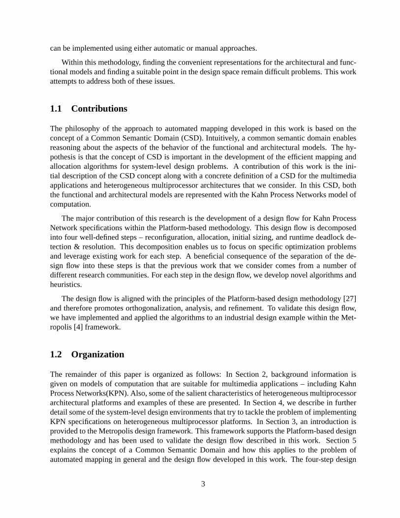
The common semantic domain we choose for this design flow contains the following elements:execution actions taken by a single thread, blocking read actions to FIFOs, and non-blocking writeactions also to FIFOs. The read and write actions to any given FIFO are guaranteed to obey mutualexclusion constraints to avoid race conditions. In effect, we have chosen the common semanticdomain that is roughly equivalent to the KPN model of computation. Figure 5 shows a graphicalview of this domain. In effect, the services used by the functional processes (F1, F2, F3, F4) areprovided by the set of architectural processes (F1, F2, F3, F4, F5). The cost functions, which arenot shown in this Figure, are used to choose a particular “covering” of the functional processesby the architectural processes. This gives only a rough view of the mapping problem, it will bespecialized further in Section 6.
6 Design Flow
After we have expressed the functional and architectural models in a common semantic domain,we can carry out the analysis necessary for determining a mapping between these two models. Inthis Section, an automated design flow will be described that is applicable to the common semanticdomain of Kahn Process Networks. The design flow associates the functional and architecturalmodels together in such a way that the cost function of interest (typically energy or latency) isoptimized. This design flow is divided into four distinct steps.
Implementing this design flow as a single step by solving a single optimization problem would
16
Figure 5: The common semantic domain decomposes the architectural and functional models intoa common set of primitives
possibly produce the best quality implementation. However, this direct approach suffers from atleast three major problems. First, due to the many different aspects of the mapping that this unifiedproblem would need to take into account, it would be quite large and very complex. Second,an amalgamated formulation would leave little opportunity for designer intervention. Designerswould be unable to easily customize the flow or incrementally restrict the design space, both ofwhich may be desirable in practice. Finally, a single-step optimization problem would necessarilybe customized for this particular design problem. Optimization approaches from related areascould not be used and relying on prior work would be difficult.
The alternative flow that we propose is divided into several clearly defined steps. Optimalityof the final solution may be lost because of the decoupling between these steps, but it does resultin a set of tractable problems that are amenable to designer intervention. The designer can iterateover a specific step or set of steps in the flow until she is satisfied with the results. Perhaps mostimportantly, the problems at each step in the design flow can leverage prior work and utilize well-studied approaches. A summary of the design flow is presented in Figure 6.
In this Section, we will describe the four major steps of the design flow in more detail. Wewill develop algorithms and heuristics that can be utilized to automate each step. Section 6.1describes the initial step of manipulating the architectural and functional models in an effort tomake them more compatible according to certain metrics. Section 6.2 explains the most importantstep of the design flow – the allocation of computational and communication resources from thearchitectural model to entities in the functional model. In Section 6.3, the heuristics used to initiallyallocate resources to the communications channels will be described. In Section 6.4, we developsystem-specific algorithms to detect and resolve artificial deadlock situations at runtime. Finally, inSection 6.5, a brief overview is provided of the support for this design flow within the Metropolisframework.
17

Figure 6: Overview of Design Flow
6.1 Step 1: Reconfiguration of functional and architectural models
In preparation for mapping the functional model with an architectural model, we may like to ma-nipulate these models in order to optimize for certain design metrics. This step is akin to thekerneling and factoring operations described in Section 5.3. Approaches for manipulating the ar-chitectural and functional models will be described in Sections 6.1.1 and 6.1.2 respectively. It isimportant to note that this first stage of the design flow is meant to provide a starting point. Incre-mental improvements to this initial configuration can be achieved by iterating between the first andsecond steps in the design flow, although we do not explore these iteration activities further here.
6.1.1 Architectural Reconfiguration
If the architectural model represents a set of architectural platform instances, architectural recon-figuration attempts to choose a particular platform instance according to the desired metrics. If thearchitectural model does not have any parameters that need to be set, then architectural reconfig-uration is not possible. The architectural reconfiguration step restricts the freedom encoded intothe architectural model by fixing some of the parameters that need to be fixed. For instance, thearchitectural platform may allow a choice in the number of processors that are utilized. If latency isthe metric of interest, then increasing the number of processors is likely beneficial. In the commonsemantic domain we are considering, this corresponds to an increased capability for concurrent ex-ecution. On the other hand, if power is the main metric, then increasing the number of processorsmight not be the best choice. Similarly, tradeoffs can be explored for the number of buses in thearchitectural model and other parameters.
Architectural reconfiguration can be carried out with a rough idea of the functional model thatwill later be mapped to it. This type of information is typically utilized in workload analysis, whichattempts to choose an architecture which is well-suited for a class of functional models that will be
18
implemented on it.
6.1.2 Functional Reconfiguration
Functional reconfiguration manipulates the representation of the functional model such that it be-comes better suited for association with architectural models according to certain metrics. Theconstraint on functional reconfiguration is that it should not affect the behavior of the functionalmodel, only the representation. This implies that the types of functional reconfiguration that canbe carried out are limited to the types of analysis that can be carried out in the semantic domain.
Here, we describe a simple type of functional reconfiguration that can be performed withinthis domain – Kahn process clustering. The constraint for this reconfiguration is to preserve theoriginal behavior. The cost metric we are trying to manipulate is the amount of concurrency inthe functional model. Too little concurrency may not be desirable since it may not completelymake use of the architectural capabilities. Too much concurrency may not be desirable since itmay require too much overhead to eventually manage in the architecture, which may increase theoverall latency. Prior work along these lines has been described in [50], although the algorithmdeveloped here is unique.
Clustering attempts to reduce the concurrency in the functional model such that a particularconcurrency constraint from the architecture is met. Suppose the architectural model providesa maximum number of concurrent tasks that can be effectively handled. For instance, an archi-tectural platform instance with 3 processing elements with a minimalist task scheduler on eachelement may only be able to support a maximum of 10 concurrent tasks. In this case, if the orig-inal functional model contains more than 10 processes, we cannot simply carry out a one-to-onemapping between functional processes and architectural tasks.
Clustering reduces the concurrency in the functional model by merging together functionalprocesses. Assume that a set of original processes is clustered to produce a single merged process.The behavior of the merged process appears indistinguishable to the rest of the system from the be-havior of the set of original processes. This means that the merged process has the same number ofinput and output channels as the set of original processes (modulo the channels that are subsumedin the merging).
To determine which processes must be merged, we need to get an idea of the communicationrequirements between processes in the original functional model. Since we assume that, in gen-eral, the internals of a process cannot be analyzed, we must rely on simulation-based profiling todetermine the processes to be merged. The information we need to obtain from these processes re-lates to the relative amount of communication between them. Since functional models in KPN aredeterministic and not affected by scheduling, cost or any other effect of the architectural platform,this information can be obtained directly from the functional model.
As a heuristic, we can merge together any two processes that have a high degree of communi-cation between them and minimal communication with other processes. This pairwise merging canbe carried out iteratively until the constraint from the architectural model is satisfied. The imple-mentation of a merged process stitches together the implementations of the two original processes
19
along with wrapper code to handle the newly internalized communication. Of course, this heuristicis order-dependent and will not give the optimal results, but it has polynomial-time complexity.
In general, this type of functional process merging is very flexible. In fact, techniques likequasi-static scheduling [38] can be applied to stitch together code from multiple processes. This isdone in an effort to reduce the reliance on dynamic schedulers from the architectural platform.
However, it is important to note that this particular type of clustering makes certain assump-tions. For instance, we assume that the internalized communication that occurs as a result ofclustering can be supported by the data memory resources available to a single process. In general,this may not be true for the communication between arbitrary processes in a KPN.
6.2 Step 2: Allocation of Computational and Communication Resources
The allocation step is perhaps the most important in the design flow since it is the first in whichthe functional and architectural models are explicitly associated with each other. The input to thisstep is an architectural model and a functional model, both represented in the common semanticdomain of KPN. The output is a system where the computational and communication services inthe functional model are associated with counterparts from the architectural model. Allocation iscarried out by solving a covering problem which ensure that all of the services being used in thefunctional model are covered by the services from the architectural platform.
For the specific KPN design flow being described, the functional model determines how theservices are used, while the architectural model determines the cost of providing these services.The semantics of the KPN model of computation allows us to make this type of distinction sincethe cost of carrying out the basic communication and computation services does not influence thebehavior of the system.
As a reminder, in this flow, the common semantic domain consists of user-specified compu-tational services along with read and write services. For the allocation problem, the architecturalplatform provides these services, while the functional specification utilizes the same services. Thequantities of interest in the architecture such as time or power do not constrain the covering prob-lem, but serve as parameters to the cost function. To enable a good quality allocation accordingto requisite metrics, we need to characterize the cost of the services provided by the architecturalplatform.
We can view the architectural platform as a set of architectural resources connected togetherin a specific configuration. Each architectural resource provides a certain set of services and itselfmay utilize other services. For instance, consider a CPU that provides read, write, and executionservices. To provide the read and write services, the CPU utilizes the transfer services of a buscomponent.
At the architectural component level, if we are able to specify the cost of providing services andthe dependencies between the utilized services and the provided services in terms of the requiredmetric (time, power, etc), then we can compose these costs together to obtain the cost of servicesat the top-level architectural model. In Section 6.2.2, we will briefly focus on this decomposition.First, however, we will evaluate some previous work that has been carried out in this area.
20

6.2.1 Prior Work
Static allocation of resources is one of the most common types of tasks that any mapping problemneeds to consider. Often, this static allocation needs to be carried out from estimates of the dynamicbehavior of the system. Many of the KPN-specific system-level design frameworks described inSection 4. The approach described here differs in the sense that it deals with a generic notionof services and cost and can therefore be customized to the specific allocation problem beingconsidered.
Statically capturing metrics of interest from simulation or other types of analysis is crucial.A overview of metrics that are considering important from a system-level design perspective isprovided in [48]. The approach developed here only focuses on one metric – intensity – and costsgiven in relation to this intensity but can easily be extended to consider additional metrics.
6.2.2 Determining Service Cost
In general, we can view the architectural platform as an interconnection of components. Eachcomponent provides a certain set of services and may utilize some set of services. During theexecution of the system, architectural services are utilized - driven by the requests of the functionalprocesses. One of the aims of the allocation step is to estimate the cost of utilizing these servicesstatically. In this section, we will describe a simple procedure that accomplishes this aim.
Let each component in the architecture provide a set ofn services. Assume each of thenservices provided by the component is annotated with anintensityvariable. Define the intensityas a static estimate of the frequency by which the services are utilized in the system at runtime.Practically, the intensity may indicate the number of read actions carried out in a single time unit.Let these intensity values be represented by the variablesi1, i2, ..., in.
The component incurs a certain cost for providing each service. Assume that this cost is speci-fied by the component in terms of the intensities of the provided services. Let these costs be givenby the functionsc1(i1, ..., in), ..., cn(i1, ..., in). Also, the component utilizes certain services in or-der to carry out the services that it provides. Let there bem such services which are utilized bythe component. The component must specify the intensity of service usage as well. This will bedone in terms of the intensity of services that are provided. So, for them services utilized by thecomponent, we obtain a set of intensitiesf1(i1, ..., in), ..., fm(i1, ..., in). An architectural compo-nent that provides two services, uses one service, and is annotated with genericc andf functionsin this manner is shown in Figure 7.
Figure 7: Service cost and output intensities annotated for a simple architectural component
21
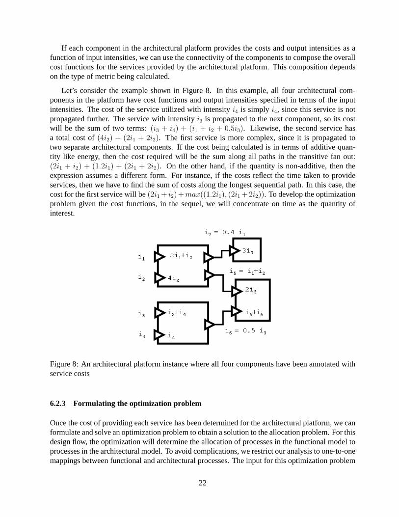
If each component in the architectural platform provides the costs and output intensities as afunction of input intensities, we can use the connectivity of the components to compose the overallcost functions for the services provided by the architectural platform. This composition dependson the type of metric being calculated.
Let’s consider the example shown in Figure 8. In this example, all four architectural com-ponents in the platform have cost functions and output intensities specified in terms of the inputintensities. The cost of the service utilized with intensityi4 is simply i4, since this service is notpropagated further. The service with intensityi3 is propagated to the next component, so its costwill be the sum of two terms:(i3 + i4) + (i1 + i2 + 0.5i3). Likewise, the second service hasa total cost of(4i2) + (2i1 + 2i2). The first service is more complex, since it is propagated totwo separate architectural components. If the cost being calculated is in terms of additive quan-tity like energy, then the cost required will be the sum along all paths in the transitive fan out:(2i1 + i2) + (1.2i1) + (2i1 + 2i2). On the other hand, if the quantity is non-additive, then theexpression assumes a different form. For instance, if the costs reflect the time taken to provideservices, then we have to find the sum of costs along the longest sequential path. In this case, thecost for the first service will be(2i1 + i2)+max((1.2i1), (2i1 +2i2)). To develop the optimizationproblem given the cost functions, in the sequel, we will concentrate on time as the quantity ofinterest.
Figure 8: An architectural platform instance where all four components have been annotated withservice costs
6.2.3 Formulating the optimization problem
Once the cost of providing each service has been determined for the architectural platform, we canformulate and solve an optimization problem to obtain a solution to the allocation problem. For thisdesign flow, the optimization will determine the allocation of processes in the functional model toprocesses in the architectural model. To avoid complications, we restrict our analysis to one-to-onemappings between functional and architectural processes. The input for this optimization problem
22

is two sets of processes: the setU of users from the functional model and the set ofP of providersfrom the architectural model. Due to the assumption of one-to-one mapping, it is required that|U | ≤ |P |.
Each element in the set of users and the set of providers has an associated set of services. Forinstance, a user process from the functional model has an associated set of execution, read, andwrite services that it needs to utilize. Although the formulation of the optimization is greatly sim-plified if the set of used services is the same as the set of provided services, we consider a slightlymore complex situation here. In this formulation, we allow one-to-many mappings between usedservices and provided services. These mappings are allowed to be dependent on the variables ofthe optimization problem (i.e. they cannot be merely parameters of the optimization). This typeof relationship between these services is influenced by the allocation of users to producers. Theintroduction of this complexity is motivated by the usage of the communication services by thefunctional processes. In the functional model, there is no differentiation between a read to localmemory and a read to global memory, since the functional model is independent of any such archi-tectural artifacts. On the other hand, this type of differentiation is important to take into accountin the architectural model, since the costs are very different. Therefore, the set of used serviceschosen remains execution, read, and write while is the set of provided services is expanded to con-tain execution, local read, local write, global read, and global write. The allocation procedure istasked with the responsibility of relating the used read and write services with their local and globalcounterparts from the set of provided services. Note that the option of considering global commu-nication even when local communication is possible might be necessary if local buffer memory isinsufficient. However, information relating to memory and buffer space is deferred to the latter twosteps in the design flow.
Returning to the formulation, we can define two additional sets: the setUSERV of usedservices and the setPSERV or provided services. The one-to-many constraint on these setsmanifests itself as a requirement that|USERV | ≤ |PSERV |. For each memberSPLIT of thesetUSERV that may be mapped into multiple provided services, there are two members in theset ofPSERV : LOCAL andGLOBAL.
In order to determine how the usage of a read service translates into a global or local read, wehave to reason about the connectivity between the users and the providers. This necessitates theinsertion of additional information into the formulation. For instance, all read and write actionsfrom the user processes originate from user-to-user communication. On the architectural side,global reads are differentiated from local reads based on the two users to which this communicationcorresponds. We restrict the exploration to always choose the local communication option if this isavailable. If both users are mapped onto the same processor, then the read actions will be assignedonto local reads, whereas if the two users are on separate processors, then the reads will have to gothrough the bus and will become global reads. Therefore, a setC of components is introduced intothe formulation, where a component corresponds to a processor.
After setting up the initial sets used in the optimization problem, we can examine the para-meters that represent the functional and architectural models in the formulation. The parametersare summarized in Table 1. Theserviceweightparameter determines the weighting of each pro-vided services in the overall cost function. Thebondinganduser intensityintensity parametersare obtained from the functional model and indicate the amount of grouping between functional
23

Parameter Name Domain Range Boundsserviceweight PSERV R ≥ 0
bonding U × U R ≥ 0,≤ 1user intensity U × USERV Z ≥ 0
provider to component P × C Z ≥ 0,≤ 1cost coefficient P × PSERV × P × PSERV Z ≥ 0
Table 1: Parameters for the Optimization Problem
processes and the intensity of service usage respectively. Theprovider to componentparameter isobtained from the architectural model and represents the assignment of tasks to processors. Finally,thecost coefficientparameters provide an encoding of the top-level cost functions (as described inSection 6.2.2) for each provided service as a linear combination of the costs of all provided ser-vices. In order to ensure the tractability of the optimization problem, we restrict the cost functionsto be linear functions of the intensities. Since the architectural platform does not have fan-out fromprovided services to used services (there is only one bus), the complications related to calculatinglatency in the presence of fan out are avoided.
Variable Name Domain Range Boundsassign U × P Z ≥ 0,≤ 1
provider intensity P × PSERV R ≥ 0usersto users U × U Z ≥ 0,≤ 1
usersto components U × C Z ≥ 0,≤ 1usedto provided U × USERV × PSERV R ≥ 0,≤ 1
Table 2: Variables for the Optimization Problem
The variables for the optimization problem are summarized in Table 2. The main job of theoptimization problem is to assign each user to a provider. This is reflected in theassignvari-able. It is important to note that theassignvariable is the main variable in the optimizationproblem and the other variables are simply derived variables that make the constraints simpler.Theprovider intensityvariable determines the intensity of usage for each provided service of eachprovider. Theusersto usersvariable has a value of1 iff the two users are allocated to the samecomponent. In order to determine this information, the helper variableusersto componentsre-flects the assignment of users to components, equivalently, functional processes to architecturalprocessors. Finally,usedto provideddetermines the breakdown of the one-to-many mapping forthe read and write services.
Now, the constraints can be formulated in terms of the given variables and parameters. First,we need to ensure that each user is assigned exactly one user and that each provider is assigned atmost one user.
24
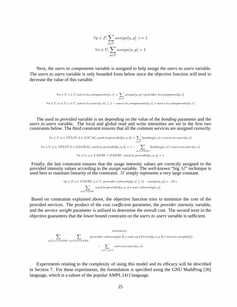
∀p ∈ P,∑u∈U
assign[u, p] <= 1
∀u ∈ U,∑p∈P
assign[u, p] = 1
Next, theusersto componentsvariable is assigned to help assign theusersto usersvariable.Theusersto usersvariable is only bounded from below since the objective function will tend todecrease the value of this variable.
∀u ∈ U, c ∈ C, users to components[u, c] =X
p∈P
assign[u, p] ∗ provider to component[p, c]
∀u ∈ U, w ∈ U, c ∈ C, users to users[u, w] ≤ 1− users to components[u, c] + users to components[w, c]
Theusedto providedvariable is set depending on the value of thebondingparameter and theusersto usersvariable. The local and global read and write intensities are set in the first twoconstraints below. The third constraint ensures that all the common services are assigned correctly.
∀u ∈ U, a ∈ SPLIT, b ∈ LOCAL, used to provided[u, a, b] =X
x∈U
bonding[u, x] ∗ users to users[u, x]
∀u ∈ U, a ∈ SPLIT, b ∈ GLOBAL, used to provided[u, a, b] = 1−X
x∈USERS
bonding[u, x] ∗ users to users[u, x]
∀u ∈ U, a ∈ USERV ∩ PSERV , used to provided[u, a, a] = 1
Finally, the last constraint ensures that the usage intensity values are correctly assigned to theprovided intensity values according to theassignvariable. The well-known “bigM ” technique isused here to maintain linearity of the constraint.M simply represents a very large constant.
∀p ∈ P, s ∈ PSERV, u ∈ U, provider intensity[p, s] ≥ (1− assign[u, p]) ∗ −M+X
a∈USERV
used to provided[u, a, s] ∗ user intensity[u, a]
Based on constraints explained above, the objective function tries to minimize the cost of theprovided services. The product of thecost coefficientparameter, theprovider intensityvariable,and theserviceweightparameter is utilized to determine the overall cost. The second term in theobjective guarantees that the lower bound constraint on theusersto usersvariable is sufficient.
minimize :X
p∈P,s∈PSERV
X
a∈P,b∈PSERV
(provider intensity[a, b] ∗ cost coefficient[p, s, a, b] ∗ service weight[s])
−X
u∈U,w∈U
users to users[u, w]
Experiments relating to the complexity of using this model and its efficacy will be describedin Section 7. For these experiments, the formulation is specified using the GNU MathProg [36]language, which is a subset of the popular AMPL [41] language.
25

6.3 Step 3: Assigning Initial Channel Sizes
After the computational and communication resources have been assigned in the allocation, wenow turn to the final type of association that needs to be carried out between the functional andarchitectural models: that of allocating the memory or buffer resources. This is manifested bychoosing the initial size of the communication channels in the functional model and associatingthem with memory components in the architectural model.
This type of allocation has the potential to change the behavior of the system. Specifically,artificial deadlock situations may develop if the channel sizes are not chosen appropriately. Un-fortunately, determining the channel sizes statically is undecidable in general for the KPN modelof computation. This fundamental undecidability is why the allocation of memory resources hasbeen partitioned into two steps in the design flow. In the current step, the channel sizes are assignedstatically. In the subsequent step in the design flow, a runtime manager process is deployed on thesystem in an attempt to ensure that artificial deadlock situations do not affect the overall behavior.
The initial sizing of a communication channel influences the degree of coupling between thereader and writer processes and also affects the likelihood of deadlock. If the channel size is large,then it can effectively serve as a buffer between the reading and writing actions of the associatedprocesses. If it is small, then the frequent interleaving between the read and write actions needs tooccur, slowing the progress of both processes.
The input to this step in the design is an allocated system where the computational and com-munication actions in the functional model have been associated with an architectural model. Allreads and writes to the channels in this allocated system inherit the temporal characteristics of thearchitectural platform. With the allocation decisions made in the previous step, we also obtainconstraints on the amount of memory that can be allocated to subsets of channels in the system.For instance, if five channels in the system are assigned to a architectural memory component witha size of 100 words, then the sum of initial sizes of these channels must be less than 100. There-fore, the major task in this step of the design flow is to partition the available memory between thechannels in the system.
The sizing decisions taken in this step may need to be modified if deadlock situations develop.Under these circumstances, additional memory may be allocated to or removed from certain chan-nels in the system. This is described in detail in the final step of the design flow in Section 6.4.
6.3.1 Prior Work
The prior work in the initial sizing of communication channels comes from the NoC and distributedsystems communities. Sizing of buffers based on simulation is explored in [11]. Sizing based onformal analysis of processes is given in [31]. Finally, [3] develops sizing in the context of highlevel synthesis.
26

6.3.2 Approach
The approach we use utilizes the temporal information that is available to us after the allocationstep in the design flow. Specifically, we can profile the production and consumption characteristicsof the allocated system on a set of representative traces. To run this initial simulation, we size eachchannel such that it hypothetically uses the maximum memory allowed by the memory constraints.For instance, if we know that channels 1, 2, and 3 together need to fit within a memory block of 30words, then each channel will be hypothetically sized to 28 words (the minimum size of a channelis 1 word).
Two pieces of data are recorded from each channel in the system during this hypothetical-sizesimulation. First, the probability histogram for the number of tokens in the channel is recorded. Forthis histogram, the x-axis has integer values that range from zero to the maximum hypothetical sizeof the channel, while the bar associated with each of these integer values indicates the probabilitythat the channel had the corresponding number of tokens during the course of the simulation. Thesecond piece of data recorded during this simulation is amount of data actually transferred throughthe channel during the simulation. The data transfer amount is useful to track since it represents therelative impact of the channel to the latency of the system. Channels which have a high throughputof data impact the latency of the system more when processes block on these channels.
The data from these hypothetical initial simulations is used to weight the channels in the sizingprocess. Channels which are judged to be more critical are allocated larger amounts of memoryduring the partitioning process. Criticality is based on the relative comparison between the datatransfer amounts and the histograms obtained for each channel.
The initial sizing approach is only a heuristic to statically partition available system memorybetween the channels in the system. This initial partitioning may need to be modified if artificialdeadlock develops in the system. This is handled in the subsequent step of the design flow.
6.4 Step 4: Runtime Deadlock Detection and Resolution
In general, the problem of determining bounds on channel sizes for KPNs so as to prevent artificialdeadlock is undecidable. In this step, we will investigate heuristic runtime algorithms that monitorthe state of channels in the system, and respond to different types of deadlock situations.
From the literature, we know that only directed or undirected cycles in a KPN can cause arti-ficial deadlock to occur [19]. If all of the processes in the system are blocked, and at least one isblocked on a write operation due to insufficient space, then we know that a global deadlock situa-tion has occurred. On the other hand, if processes in a directed or undirected cycle are blocked, andat least one of them is write-blocked, this is termed as local deadlock. In either of these situations,the deadlock can only be resolved by allocating extra memory to a communication channel.
However, which channel needs to be allocated memory, and the amount of memory to allocatesuch that the deadlock is resolved with the least amount of extra memory is undecidable in general.As with previous steps, we can tailor this decision based on the structure and profiling of thesystem.
27

Practically, we have not seen any evidence that any of the KPN-specific system-level designenvironments mentioned in Section 4 implement any form of deadlock detection and resolution.From a theoretical point of view, this is not sufficient, since static sizing is not enough given ageneral KPN specification. However, practically, the applications are used with these types of en-vironment may not require this step. For instance, moving to more restricted forms of specificationsuch as static dataflow would remove the need for this step from the design flow, but would alsoconstrain expressiveness.
6.4.1 Prior Work
Parks [42] is the first to provide a strategy for dealing with artificial deadlock. Parks’ algorithminvolves waiting for all processes in the system to become deadlocked, and then increasing the sizeof the smallest channel in the system until at least one process becomes unblocked. Geilen andBasten [19] consider artificial local deadlock and attempt to explain why it may be useful to detectand correct this to guarantee a correct execution of the KPN. There has been fairly little workon coming up with other heuristics for deadlock resolution. Suggestions described in [8] lay outstrategies based on reclaiming previously allocated memory. We develop these strategies furtherin this step of the design flow.
6.4.2 Deadlock Detection
The aims for deadlock detection algorithms are two-fold: to find all instances of deadlock assoon as possible after they occur and to avoid false positives. The first aim is important sincethe occurrence of a deadlock usually prevents the system from producing further output and addslatency. The second aim prevents the waste of scarce memory resources. Also, the deadlockdetection procedure itself should not add excessive latency to the system.
There are many instances in the literature of distributed deadlock detection algorithms [17].These algorithms usually assume a polling type of mechanism by which processes in the systemcan check the status of resources that are requested. In order to adapt this mechanism to Kahnprocesses, we would have to place wrappers around each process that would be able to checkFIFO status. Synthesizing a system scheduler [16] is another approach that can be taken. Thisapproach may be effective, but may not be suitable for all applications.
We take a different approach which relies on a separate process in the system that detects andresolves deadlock situations. In the sequel, this will be referred to as the manager process. Theinput to this step in the design flow is an allocated system with initial sizes for the channels. Theoutput is a deadlock manager process which is customized for the system being managed.
The manager can serve either as a distributor of shared resources or as an observer that influ-ences the rest of the system only when necessary. The first role requires that all requests for readingor writing be “approved” by the manager before they can proceed. The manager can keep trackof the resource contention graph of the system and take action when deadlock is imminent. Thebenefit of this approach is that deadlock situations can be detected immediately. The downside is
28

that the overall performance of the system is severely compromised by the bottleneck through themanager process. In effect, the parallelism of the system is severely reduced.
In the second role, the manager occasionally probes the channels in the system to determine ifa deadlock has occurred. This implies that a deadlock may not be immediately detected. However,in the absence of a deadlock, the parallelism of the system is not restricted. The maximum amountof time required to detect a deadlock can still be bounded based on the scheduling of the processesin the system.
In our approach, we adopt the former role for the manager process. The behavior of the man-ager is to periodically monitor the status of each of the channels in the system. A channel can beone of three states: normal, read-blocked, or write-blocked. If the manager finds a cycle of chan-nels that are blocked, and at least one of these channels is write-blocked, then an artificial deadlockhas been found. Alternatively, to detect global deadlock situations, the manager can wait until allprocesses in the system are blocked, and at least one is write-blocked. Once a deadlock situationis detected, the manager invokes the deadlock resolution heuristic described in Section 6.4.3.
More specifically, to detect deadlock, the deadlock manager at runtime maintains a list ofchannel entries. There is a single channel entry for each channel in the system. Each channel entryalso carries the ID of the reader and writer processes for the channel. Process IDs are assumed tobe unique in the system. The channel entry has a status field which the manager can update. Everytime it is run, the manager process reads the status of each channel in the system. The status fieldis marked as normal, read-blocked or write-blocked for each channel. A write-blocked channelis a full channel to which its writer has attempted to write, therefore blocking the writer process.Similarly, a read-blocked channel is an empty channel from which the reader has attempted to read,blocking the reader process. A normal channel is a channel which is not in either of the prior twosituations.
Once the status of all the channels in the system has been obtained, the manager carries out adepth-first search (DFS) procedure starting at each write-blocked channel to detect local deadlock.The DFS search only considers the read or write blocked channels, it ignores all normal channels.If the DFS procedure ever returns to the base channel, then a cycle of blocked processes has beenfound. All write-blocked channels within this cycle (including the base channel) are marked witha tag that indicates that they are candidates for deadlock resolution.
If only global deadlock is being detected, then the procedure is much simpler. The managersimply determines that all the channels in the system are blocked, and at least one channel iswrite-blocked. Then, all write-blocked channels are similarly tagged for deadlock resolution.
6.4.3 Deadlock Resolution
The challenge is deadlock resolution lies in the fact that system memory is typically a scarceresource. A “good” deadlock resolution approach allocates available memory to channels in sucha way that the deadlock is resolved with a minimum amount of extra memory. According to thismetric, determining an optimal allocation strategy is undecidable. In this section, we investigateheuristics that attempt to develop system-specific allocation strategies that work well in practice.
29
Deadlock resolution can only be accomplished by allocating additional memory to channels inthe system at runtime. After the deadlock manager has detected a deadlock situation (either globalor local), the next step is to allocate additional memory to the tagged channels in order to allow theblocked processes to proceed.
Most prior work on artificial deadlock resolution in the literature adopts a very simple approach.Typically, the smallest write-blocked FIFO involved in a deadlock is allocated additional memoryuntil the deadlock is resolved. This is the approach adopted by [2] and [40].
A key component of the approach that we develop here is the concept ofreclaimingpreviouslyallocated memory. This means that if the manager previously allocated a certain amount of extramemory to a particular channel due to a deadlock situation, in subsequent deadlock situations, thisextra memory (if it is not in use) can be reclaimed by the manager. The newly reclaimed memorycan then be allocated to other channels that may require it. A possible downside of reclaimingpreviously allocated memory is that resolved deadlocks may crop up again.
More specifically, the resolution algorithm in the deadlock manager first obtains a list of allthe tagged channels in the system. The tagged channels represent write-blocked channels that areinvolved in either local or global deadlock situations. The deadlock manager controls access to apool of shared memory in the system. To resolve the deadlock, the deadlock allocates some of thememory in the pool to a tagged channel. If no more memory remains in the pool, the managerattempts to obtain previously allocated memory from the pool which is no longer being used. Iftagged channels exist, the pool is completely allocated, and no previously allocated memory canbe reclaimed, then the manager has no recourse but to raise an exception. Ultimately, this is thesituation we would like to prevent with heuristics.
To decide which channel to allocate memory and the amount of extra memory to allocate, werely on additional information in the list of channel entries that the deadlock manager maintains.In addition to a reader ID, a writer ID, and a status field, the channel entries are assigned anotherparameter. This parameter is an integer which corresponds to the worthiness of that channel toreceive additional memory, and is initially derived from the initial sizing information obtained inthe previous section. In particular, the worthiness initially is:
worthinessi = (maxsize− sizei) ∗ throughputi
In this assignment,maxsize is the largest size of any channel in the system, while the sizeand throughput of the current channel are given bysizei andthroughputi respectively. When adeadlock is detected, the channel with the highest worthiness value is allocated additional memoryequal to a fixed fraction of the remaining memory in the pool. The worthiness value of the channelis reduced since the size of the channel is increases.
If no more memory remains in the pool, memory is collected until a predefined amount isonce again gathered. The memory is recovered from channels that have been previously allocatedmemory and whose worthiness metrics are the lowest. Intuitively, this avoids thrashing, wherethe same channels are allocated and deallocated memory repeatedly. Of course, the deadlockresolution algorithm described here is merely a heuristic, and in the worst case, when no morememory remains in the pool, and no memory can be recovered, the manager raises a flag and the
30
system must be reset.
6.5 Integration with the Metropolis framework
The algorithms and approaches described for each step of the design have been implemented withinthe context of the Metropolis design framework. In this Section, the mechanics behind this inte-gration will be described.
First, a library was created to support the KPN model of computation and to allow the types ofoperations on channels that are needed in the design flow. The components of this library includemedia describing the channels that are template-based to handle different data types. Generic pro-cesses are also defined within this library, so that it becomes relatively easy to subclass this genericprocess and implement real functionality. An implementation of the deadlock manager process isalso implemented within the library. The deadlock manager is initialized with a structural represen-tation of the functional model, so that it can carry out the DFS algorithms and allocate/deallocatememory as required.
An integral part of this library is the interfaces that are defined for communication between theprocesses, channels, and the deadlock manager. The processes can communicate with the channelsusing the standard read() and write() functions. The deadlock manager can query the state ofa channel, allocate memory to it, and deallocate unused memory that was previously allocated.Careful use of mutual exclusion is made in the implementation of the channels to avoid unnecessarydeadlock or race conditions.
Along with components of the functional model, the primitives required for the architecturehave also been implemented or adapted from existing designs. In particular, non-deterministictasks, processor media, a bus medium, memory media, first-come-first-server (FCFS) schedulers,and a GlobalTime quantity manager have all been utilized for the architectural modeling. Theinteraction between the processors and the GlobalTime quantity manager is carried out in such away that it is relatively easy to change the costs associated with the services. Also, the entire archi-tectural model is easy to reconfigure with regards to the number of processors that are instantiated,the number of tasks on each processor, and the size of the memory components.
7 Experimental Results
In this section, we will apply the algorithms developed in Section 6 to an industrial set-top boxsystem. The experiments concentrate on the second and third steps in the design flow: allocationand initial sizing. The application for this system is a Picture-in-Picture component used in digitaltelevision. A block diagram of this application is shown in Figure 9. The architectural platform isa heterogeneous multiprocessor architecture of the type shown in Figure 10.
31

Figure 9: Picture-in-Picture Application
Figure 10: Architectural Platform
7.1 PiP Application
The PiP application takes as input two MPEG streams and outputs a single MPEG stream. Framesfrom the first input MPEG streams are resized and placed within a window. These frames are theninserted into a specific portion of the frames from the second input stream. In the set of experimentsdescribed here, we choose to focus on the core of the PiP application, which involves the horizontaland vertical resizing of frames from the first input stream. The resize component was modeled inMetropolis with 26 concurrent processes and 57 channels, not including the deadlock manager.Block diagrams of the horizontal and vertical resize blocks, which together constitute the resizecomponent, are shown in Figures 11 and 12. The source and sink processes are inserted into thefunctional model to model the data production and consumption characteristics of the rest of theapplication.
32

Figure 11: Horizontal Resize Component
7.2 Heterogeneous Multiprocessor Architectural Platform
The architectural platform used in the experiments consists of a set of processors, local and globalmemories and a system bus. The platform can be configured to have a variable number of proces-sors connected to the global bus. Each processor can support multiple tasks, and grants access tothese tasks in a first-come-first-serve manner. The size of the local memory in a processor and thesystem memory connected to the bus can be parameterized.
Each processor provides a set of services to the tasks that run on it. These services are: globalread, global write, local read, local write, and execute. The execute service represents an abstractview of an instruction or block of code being executed on the processor. The read/write services areassociated with either the system memory or the local memory of the processor. These read/writeservices can be parameterized with the number of the words that are to be transferred. The cost in-curred by each processor and memory for providing the above services can also easily be changed.
For the experiments presented here, the specific configuration of the architecture has fourprocessors, each with their own local memories. The processors are all connected to a singleglobal bus component, which has a slave global memory block connected to it. The cost incurredby each processor to provide each service, in cycles, in presented in Table 3.
There are 26 tasks instantiated on this architecture, they are statically partitioned as shown inTable 4.
33

Figure 12: Vertical Resize Component
Services Proc. #1 Proc. #2 Proc. #3 Proc. #4execute 3 3 5 5
local read 2 3 2 3global read 3 4 3 4local read 6 6 6 6local write 8 8 8 8
Table 3: Service Cost on each Processor
7.3 Allocation Experiments
The first set of experiments carried out on the PiP system explores the effectiveness of the alloca-tion algorithm described in Section 6.2. The aim here is to test the predictive capabilities of theformulation. Specifically, fidelity is the measure by which the success of the allocation optimiza-tion can be evaluated. Fidelity is the correspondence between the total orders assigned to the costof feasible allocations by the objective function and actual system simulation. In other words, ifthe objective function predicts that an allocationa has lower cost than another allocationb, thenthe cost ofa obtained via system simulation should also be better than the costb.
Simplified cost functions for the architectural services are used for these experiments, wherethe cost of utilizing a particular service is independent of the intensities of other services on thesame component. This simplification makes the formulation much simpler, but sacrifices some ofthe expressiveness that can potentially make the formulation more accurate. The costs are taken
34

Processor Tasks1 1–62 7–123 13–194 20–26
Table 4: Assignment of Tasks to Processors
directly from Figure 3. The formulation as given in the Appendix is automatically translated to theMPS file format and given as input to IBM’s OSL solver. All of the optimizations described hereare run on a dual 3.0 GHz linux machine with 4 Gb of memory. The initial sizes of the communica-tion channels were made high enough such that they effectively simulate infinite channel memory.In other words, no write-blocking takes place for any channel for all the experiments here. Effectsof reducing the memory size will be explored in Section 7.4.
In the first experiment, the objective function is modified to only minimize the inter-componentcommunication in the system and not consider the latency cost at all. This modified objectivefunction can be thought of solving just the min-cut problem for the allocation. The best feasibleresult returned by the ILP solver after 15 minutes of execution is recorded and referred to asSolution 1. Due to the handicapping of the objective function, Solution 1 should exhibit worseresults than the other experiments. The second, third, and fourth experiments consider the fullobjective function and attempt to ascertain that the objective function tracks with the actual systemperformance. Solution 2 is obtained by considering the first feasible solution found by the ILPsolver on the problem instance, whereas solution 3 considers the best solution found after 15minutes of execution, while Solution 4 is the best found after 30 minutes. These points in thedesign space are summarized in Table 5.
Soln. No. Obj. funct. Cutoff Time, minutes1 no service cost 152 full first feasible3 full 154 full 30
Table 5: Measuring the Fidelity of the Objective Function
Based on these four solutions from the optimization problem, synchronization constraints wereautomatically generated in Metropolis to reflect the allocations. The PiP system was then simulatedfor each solution, and the latency in cycles to process five frames of image data was recorded.The results are shown in Figure 13. As expected, the first solution has the worst result since theobjective function does not take into account the service cost. The remaining solutions achievebetter results depending on the amount of time that the solver was given. This shows, that at leastfor this particular case study, the formulation of the allocation optimization problem is able toestimate system performance.
35

Figure 13: System latency scales well with allocation objective function
7.4 Initial Sizing Experiments
The objective in the initial sizing experiments is to take the solution with the best overall latencyfrom the allocation experiments and progressively tighten the available memory. Then, initialsizes for all channels are assigned according to two separate algorithms. The first algorithm evenlydivides the available memory while the second algorithm is the heuristic described in the thirdstep of the design flow. The hypothesis is that as the channel sizes are reduced, the amount ofinterleaving between reader and writer processes will increase and add to the overall latency of thesystem.
In the experiments carried out here, the size of the global memory component in the architectureis reduced from its initial value, while all the local memory components remain at the same size. Tofit within the available memory, the sizes of some of the 29 channels that have been allocated to theglobal memory component must be reduced. The first algorithm divides memory evenly betweenthe available channels, so all 29 channels will be affected by a small decrease in the availableglobal memory. The second algorithm only reduces the size of a channel when necessary. Table6 shows the number of channels in the system which have their bounds reduced as a result of theheuristic sizing algorithm.
No. Global Memory Size Channels Affected1 700 02 600 63 500 144 400 205 300 256 200 297 100 29
Table 6: Number of channels affected by second sizing algorithm
The effect of both algorithms on the overall latency incurred in resizing five frames of image
36

data is summarized in Figure 14. The results show that regardless of the algorithm applied, there isa huge impact on system latency. This confirms the hypothesis that initial sizing is a very importantpart of the mapping problem. For relatively large amounts of available memory (¿ 450 words), bothalgorithms perform equally well, this is not shown in the Figure. When the amount of availablememory ranges between 20% and 60% of the initial memory, the heuristic algorithms performsbetter than the equal sizing algorithm, resulting in system latencies which are approximately 30%lower. As the available memory falls below 20% of the original, both algorithms peform badly,as expected. For this region, the heuristic does worse than the equal sizing algorithm. This isexplained by the fact that the heuristic is “trained” based on data obtained from large initial sizesof the channels. The predictive capabilities of the heuristic break down as the reduction in mem-ory becomes larger. This suggests that the heuristic can be enhanced by incorporating input dataobtained from a variety of channel sizes.
Figure 14: System latency is greatly impacted by channel size
8 Conclusions
Mapping problems are commonly encountered during system-level design. Common practice bothin industry and academia involves developing specialized algorithms for each problem. Thereis much similarity in the algorithms which are eventually developed, but the lack of a commonframework for reasoning about these problems prevents the reuse of these approaches. We havepresented an initial framework for reasoning about many different types of mapping problemsusing the concept of a common semantic domain. Even though the task of finding a commonsemantic domain given a class of functional and architectural models is very difficult, reasoningabout the properties of this domain helps determine the types of optimizations that can be applied.
37

In this work, the major contribution is a design flow for implementing Kahn Process Networksspecifications within the Platform-based design methodology. This design flow has clearly beenseparated into a number of steps. For each step in the design flow, we have outlined algorithms andapproaches to tackle the corresponding optimization problems. Experiments have been carried outon a case study in the Metropolis design framework to test the validity of some of these approaches.
9 Future Work
In the future, we would like to apply our design flow to additional case studies, to better evaluateits effectiveness. We would also like to more fully develop the concept of a common semanticdomain to allow for automated mapping. We believe that some of the ideas from this design flowcan be carried over to develop similar flows for other models of computation.
For functional modeling, it is relatively easier to capture the behavior of interest if we rely onwell-known models of computation. Capturing architectural behavior is somewhat more compli-cated. Since the architectural specification is usually captured bottom-up from characterization ofexisting physical platforms, it is not usually clear which aspects of the behavior need to be takeninto account. This work assumed that an architectural model was provided which offered a certainset of services at a certain cost. The assumption was made that the cost was accurately captured bythe cost functions provided. However, further work is required to validate this assumption. Specif-ically, we would like to correlate our architectural models better with the existing architecturalplatforms.
One of the benefits of the four-step design flow that was mentioned was the ability to build onprior work from different research communities. For the first step of the design flow, formulatingthe clustering problem with a clear cost function and building a clustering tree – or dendrogram –in the manner described in [13] is interesting to pursue. Also, a formal description of the sufficientconditions for ensuring that clustering is legal is required as well. In terms of the architecturalreconfiguration stage, linking the possible configurations of the architectural model to performancedata obtained from real designs (e.g. FPGAs) is a related topic.
For the second step of the design flow, we would like to explore heuristic approaches to solvingthe covering problem. Covering problems are a well-studied topic, and several heuristics havebeen developed that have applicability to the types of problems we consider. Two such areas arenegative thinking [21] and cutting planes [39]. Also, enhancing the formulations to deal withstatistical distributions of parameters is also an interesting area of future research since the type ofdata utilized during this step is a static estimate of dynamic behavior. Aspects such as correlationbetween service usage may be interesting to track for some kinds of cost functions.
For the third step, the results have shown the benefits and the weaknesses of the simple heuristicalgorithm that was developed. Enhancing this algorithm to deal with estimates of behavior undertight memory constraints is necessary. It might be worthwhile to obtain additional information asinput for this algorithm such as correlation between producers and consumers or a finer granularityview of the processes themselves (perhaps in the form of a CDFG).
38

For the fourth step, testing needs to be carried out to determine the effectiveness of the memoryreclamation strategy described. Even if actual designs do not require a deadlock manager, it maystill be useful to consider a manager in conjunction with the initial sizing step. For instance,simulations can be run with sample traces in which the deadlock manager allocates and deallocatesmemory as needed. Once the memory has stabilized for channels, the simulation can be stoppedand the sizes of the channels used as the initial sizes for future simulations. After running asequence of these simulations, it may be possible to converge to the set of initial sizes that willprovide the best system performance for an implementation.
Finally, a broad area of future research deals with the idea of common semantic domains forsolving mapping problems. Specifically, we are interested in applying the same concepts developedhere to distributed systems and control dominated systems. After reasonable common semanticdomains have been found for several types of mapping problems, we can then begin to extract thecommonalities in the mapping problems and more effectively consider the reuse of algorithms andheuristics.
References
[1] K. Keutzer A. Mihal. Mapping Concurrent Applications onto Architectural Platforms. pages39–59. Kluwer Academic Publishers, 2003.
[2] G.E. Allen, B.L. Evans, and D.C. Schanbacher. Real-time sonar beamforming on a unixworkstation using process networks and posix threads. InConference Record of the Thirty-Second Asilomar Conference on Signals, Systems & Computers, Vol.2, Iss., pages 1725–1729,1998.
[3] Tod Amon and Gaetano Borriello. Sizing Synchronization Queues: A Case Study in HigherLevel Synthesis. InProceedings of the 28th conference on ACM/IEEE design automation,pages 690–693. ACM Press, 1991.
[4] F. Balarin, Y. Watanabe, H. Hsieh, L. Lavagno, C. Passerone, and A. Sangiovanni-Vincentelli.Metropolis: An Integrated Electronic System Design Environment.IEEE Computer,36(4):45– 52, April 2003.
[5] Felice Balarin, Jerry Burch, Luciano Lavagno, Yosinori Watanabe, Roberto Passerone, andAlberto Sangiovanni-Vincentelli. Constraints specification at higher levels of abstraction. InProceedings of the Sixth IEEE International High-Level Design Validation and Test Workshop(HLDVT’01), page 129. IEEE Computer Society, 2001.
[6] Felice Balarin, Massimiliano Chiodo, Paolo Giusto, Harry Hsieh, Attila Jurecska, LucianoLavagno, Claudio Passerone, Alberto Sangiovanni-Vincentelli, Ellen Sentovich, Kei Suzuki,and Bassam Tabbara.Hardware-software Co-design of Embedded Systems: The POLIS Ap-proach. Kluwer Academic Publishers, 1997.
39

[7] Felice Balarin, Luciano Lavagno, and et al. Concurrent Execution Semantics and Sequen-tial Simulation Algorithms for the Metropolis Metamodel.Proc. 10th Int’l Symp. Hard-ware/Software Codesign, pages 13–18, 2002.
[8] T. Basten and J. Hoogerbrugge. Efficient execution of process networks. In A. Chalmers,M. Mirmehdi, and H. Muller, editors,Proc. of Communicating Process Architectures 2001,pages 1–14. IOS Press, 2001.
[9] B. Bhattacharya and S. S. Bhattacharyya. Parameterized modeling and scheduling of dataflowgraphs. Technical Report UMIACS-TR-99-73, Institute for Advanced Computer Studies,University of Maryland at College Park, December 1999. Also Computer Science TechnicalReport CS-TR-4083.
[10] Joseph Tobin Buck. Scheduling dynamic dataflow graphs with bounded memory using thetoken flow model. Technical Report ERL-93-69, 1993.
[11] Vikas Chandra, Anthony Xu, Herman Schmit, and Larry Pileggi. An Interconnect Chan-nel Design Methodology for High Performance Integrated Circuits. InProceedings of theconference on Design, automation and test in Europe, page 21138. IEEE Computer Society,2004.
[12] Abhijit Davare, Douglas Densmore, Vishal Shah, and Haibo Zeng. Simple case study in met-ropolis. Technical Report UCB.ERL 04/37, University of California, Berkeley, September2004.
[13] Abhijit Davare, Kelvin Lwin, Alex Kondratyev, and Alberto Sangiovanni-Vincentelli. Thebest of both worlds: The efficient asynchronous implementation of synchronous specifica-tions. InDesign Automation Conference (DAC). ACM/IEEE, June 2004.
[14] E. A. de Kock. Multiprocessor Mapping of Process Networks: a JPEG Decoding Case Study.In Proceedings of the 15th international symposium on System Synthesis, pages 68–73. ACMPress, 2002.
[15] Doug Densmore. Metropolis Architecture Refinement Styles and Methodology. TechnicalReport UCB/ERL M04/36, University of California, Berkeley, CA 94720, September 14,2004.
[16] Javed Dulloo and Philippe Marquet. Design of a real-time scheduler for kahn process net-works on multiprocessor systems. InInternational Conference on Parallel and DistributedProcessing Techniques and Applications, 2004.
[17] Ahmed K. Elmagarmid. A Survey of Distributed Deadlock Detection Algorithms.SIGMODRec., 15(3):37–45, 1986.
[18] Cagkan Erbas, Selin C. Erbas, and Andy D. Pimentel. A Multiobjective Optimization Modelfor Exploring Multiprocessor Mappings of Process Networks. InProceedings of the 1stIEEE/ACM/IFIP international conference on Hardware/software codesign and system syn-thesis, pages 182–187. ACM Press, 2003.
40

[19] M. Geilen and T. Basten. Requirements on the Execution of Kahn Process Networks. InP. Degano, editor,Proc. of the 12th European Symposium on Programming, 2003.
[20] A. Girault, B. Lee, and E.A. Lee. Hierarchical finite state machines with multiple concur-rency models.IEEE Trans. on Computer-Aided Design of Integrated Circuits and Systems,18(6):742–760, June 1999. Research report UCB/ERL M97/57.
[21] E. Goldberg, L. P. Carloni, T. Villa, R. K. Brayton, and A. L. Sangiovanni-Vincentelli. Neg-ative thinking in branch-and-bound: the case of unate covering.IEEE Transactions onComputer-Aided Design, 19(3):281–294, March 2000.
[22] Matthias Gries. Methods for Evaluating and Covering the Design Space during Early DesignDevelopment.Integration, the VLSI Journal, Elsevier, 38(2):131–183, December 2004.
[23] Thorsten Grotker.System Design with SystemC. Kluwer Academic Publishers, 2002.
[24] Intel. http://www.intel.com.
[25] G. Kahn. The Semantics of a Simple language for Parallel Programming. InProceedings ofIFIP Congress, pages 471–475. North Holland Publishing Company, 1974.
[26] G. Kahn and D.B. MacQueen. Coroutines and networks of parallel processes. InProceedingsof IFIP Congress, pages 993–998. North Holland Publishing Company, 1977.
[27] K. Keutzer, S. Malik, A. R. Newton, J. Rabaey, and A. Sangiovanni-Vincentelli. System LevelDesign: Orthogonolization of Concerns and Platform-Based Design.IEEE Transactions onComputer-Aided Design of Integrated Circuits and Systems, 19(12), December 2000.
[28] Gregor Kiczales, John Lamping, Anurag Mendhekar, Chris Maeda, Cristina Lopes, Jean-Marc Loingtier, and John Irwin. Aspect-oriented programming. In Mehmet Aksit andSatoshi Matsuoka, editors,Proceedings European Conference on Object-Oriented Program-ming, volume 1241, pages 220–242. Springer-Verlag, Berlin, Heidelberg, and New York,1997.
[29] Bart Kienhuis and Ed F. Deprettere. Modeling stream-based applications using the sbf modelof computation.J. VLSI Signal Process. Syst., 34(3):291–300, 2003.
[30] E.A. de Kock, G. Essink, W.J.M. Smits, P. van der Wolf, J.Y. Brunel, W.M. Kruijtzer, P. Liev-erse, and K.A. Vissers. YAPI: Application Modeling for Signal Processing Systems.Pro-ceedings of the 37th Design Automation Conference, 2000.
[31] Tilman Kolks, Bill Lin, and Hugo de Man. Sizing and Verification of Communication Buffersfor Communicating Processes. InProceedings of the 1993 IEEE/ACM international confer-ence on Computer-aided design, pages 660–664. IEEE Computer Society Press, 1993.
[32] E.A. Lee and T.M. Parks. Dataflow Process Networks. InProceedings of the IEEE, vol.83,no.5, pages 773 – 801, May 1995.
41

[33] E.A. Lee and A. Sangiovanni-Vincentelli. A Framework for Comparing Models of Compu-tation. IEEE Transactions on Computer-Aided Design of Integrated Circuits and Systems,17:1217–1229, Dec. 1998.
[34] Edward Ashford Lee and David G. Messerschmitt. Static scheduling of synchronous dataflow programs for digital signal processing.IEEE Trans. Comput., 36(1):24–35, 1987.
[35] Paul Lieverse, Todor Stefanov, Pieter van der Wolf, and Ed Deprettere. System Level DesignWith Spade: An m-jpeg Case Study. InProceedings of the 2001 IEEE/ACM internationalconference on Computer-aided design, pages 31–38. IEEE Press, 2001.
[36] GLPK: GNU Linear Programming Kit. http://www.gnu.org/software/glpk/glpk.html.
[37] Xiaojun Liu, Yuhong Xiong, and Edward A. Lee. The Ptolemy II Framework for Visual Lan-guages. InProceedings of the IEEE 2001 Symposia on Human Centric Computing Languagesand Environments (HCC’01), page 50. IEEE Computer Society, 2001.
[38] Y. Watanabe M. Sgroi, L. Lavagno and A. Sangiovanni-Vincentelli. Synthesis of embeddedsoftware using free-choice petri nets. InProceedings of Design Automation Conference, DAC’99, June 1999.
[39] Hugues Marchand, Alexander Martin, Robert Weismantel, and Laurence Wolsey. Cuttingplanes in integer and mixed integer programming.Discrete Appl. Math., 123(1-3):397–446,2002.
[40] F.S. Mendes, M.S.M. Silva, F.A.B. Silva, E.P. Lopes, E.P.L. Aude, H. Serdeira, J.T.C. Sil-veira, and M.F. Martins. Cpnsim: A computational process network simulator. In2003International Symposium on Performance Evaluation of Computer and TelecommunicationSystems (SPECTS 2003), v.1., pages 234–239, 2003.
[41] AMPL: A Modeling Language for Mathematical Programming. http://www.ampl.com.
[42] T. Parks. Bounded Scheduling of Process Networks. PhD thesis, University of California,Berkeley, 1995.
[43] T. Parks, J. Pino, and E. Lee. A comparison of synchronous and cyclostatic dataflow, 1995.
[44] J. Paul and D. Thomas. A Layered, Codesign Virtual Machine Approach to Modeling Com-puter Systems. InProceedings of the conference on Design, automation and test in Europe,page 522. IEEE Computer Society, 2002.
[45] Andy D. Pimentel, Louis O. Hertzberger, Paul Lieverse, Pieter van der Wolf, and Ed F. De-prettere. Exploring Embedded-Systems Architectures With Artemis.Computer, 34(11):57–63, 2001.
[46] Alessandro Pinto. Metropolis Design Guidelines. Technical Report UCB/ERL M04/40, Uni-versity of California, Berkeley, CA 94720, September 14, 2004.
42
[47] Tarvo Raudvere, Ingo Sander, Ashish Kumar Singh, and Axel Jantsch. Verification of DesignDecisions in ForSyDe. InProceedings of the 1st IEEE/ACM/IFIP international conferenceon Hardware/software codesign and system synthesis, pages 176–181. ACM Press, 2003.
[48] Donatella Sciuto, Fabio Salice, Luigi Pomante, and William Fornaciari. Metrics for DesignSpace Exploration of Heterogeneous Multiprocessor Embedded Systems. InProceedingsof the tenth international symposium on Hardware/software codesign, pages 55–60. ACMPress, 2002.
[49] A. P. Sistla and E. M. Clarke. The complexity of propositional linear temporal logics. InProceedings of the fourteenth annual ACM symposium on Theory of computing, pages 159–168. ACM Press, 1982.
[50] Todor Stefanov, Bart Kienhuis, and Ed Deprettere. Algorithmic Transformation Techniquesfor Efficient Exploration of Alternative Application Instances. InProceedings of the tenthinternational symposium on Hardware/software codesign, pages 7–12. ACM Press, 2002.
[51] Todor Stefanov, Claudiu Zissulescu, Alexandru Turjan, Bart, and Ed Deprettere. SystemDesign Using Kahn Process Networks: The Compaan/Laura Approach. InProceedings of theconference on Design, automation and test in Europe, page 10340. IEEE Computer Society,2004.
[52] The Metropolis Project Team. The Metropolis Meta Model Version 0.4. Technical ReportUCB/ERL M04/38, University of California, Berkeley, CA 94720, September 14, 2004.
[53] Xilinx. http://www.xilinx.com.
43