A novel multi-carrier waveform with high spectral ...
6
A novel multi-carrier waveform with high spectral efficiency: semi-orthogonal frequency division multiplexing Fan Yang*, Xin Wang** *Fujitsu Research and Development Center Co., Ltd, Beijing, China [email protected],[email protected] Abstract—In this paper, semi-orthogonal frequency multiplexing (SOFDM) is proposed, which has doubled spectral efficiency over OFDM by halving the subcarrier spacing. SOFDM is orthogonal in real field but non-orthogonal in complex field. To cancel the inter carrier interference caused by non-orthogonality, linear equalization algorithms are introduced based on inter carrier cross-correlation matrix. However SOFDM still suffer a performance loss due to the white noise power amplification effect of linear equalization. To further improve the performance, by use of the special property of inter carrier cross-correlation matrix, complementary SOFDM is provided, which is orthogonal in both real and complex field. It has identical spectral efficiency with OFDM but obtain a diversity gain in fading channel. And a HARQ-style flexible complementary SOFDM is introduced, which can obtain not only performance gain but also spectral efficiency gain. Keywords—semi-orthogonal frequency division multiplexing; inter carrier cross-correlation; inter carrier interference; zero forcing; minimum mean square error I. INTRODUCTION Nowadays, the exponential increase of the data traffic demand justifies the design of a novel 5th Generation (5G) radio access technology (RAT) aiming at 10 Gbps upper data rate and sub-ms latency [1]. In addition to the data rates, the number of devices will also grow exponentially. To meet these requirements, worldwide wireless communication researchers both in academic area [2] [3] and industry area start to study new technologies. New waveform, as one enabling technology, is one of the hottest topic in 5G research. Waveform can be divided into two categories: single carrier waveform and multiple carrier (MC) waveform. The latter one attracts more attention for numerous advantages. The most popular MC waveform is certainly orthogonal frequency division multiplexing (OFDM) since it is widely used in current wireless communication systems such as 3GPP LTE and WiMAX. OFDM has many advantages [4] [5] but needs perfect synchronization in time and frequency domain and it has a relative large side lobe which will make OFDM less attractive to some application such as cognitive radio [6]. Researchers continue to seek for new waveform to further increase spectral efficiency or suppress side lobe to fit to flexible access spectrum. One important waveform is filter bank multicarrier (FBMC) [7]-[10]. Instead of sinc-pulse like OFDM, its subcarriers have more choices according to filter design to reduce side lobe levels [11]. FBMC has a potential to improve spectral efficiency by enabling transmission without cyclic prefix and with reduced guard bands [12]. Conventional FBMC operates based on real-valued modulation such as offset-QAM or PAM because it is only orthogonal in real field. Recently, A QAM-based FBMC scheme has been proposed [13]. This system utilizes two different filters to even and odd subcarrier symbols so that subcarriers become orthogonal in complex plane. However, both OQAM-FMBC and QAM-FBMC have the same spectral efficiency [14]. In ideal environments such as AWGN channel, when CP is unnecessary, they still have the identical spectral efficiency with OFDM [15] [16]. In order to further increase spectral efficiency, we propose a new MC waveform which has a halved subcarrier spacing than OFDM.. As a result, the spectral efficiency is almost doubled over OFDM but the subcarriers become non-orthogonal in complex field. In fact, as we will prove later, the orthogonality only exists in even or odd subcarriers. However, these subcarriers are still orthogonal in real plane which has been noticed in first studies about multicarrier systems [17] [18]. That’s why we call it semi orthogonal frequency division multiplexing (SOFDM). The paper is organized as follows. In section II, SOFDM concept and equalization algorithm in frequency domain at the receiver side is introduced. In section III, complementary SOFDM is introduced. And simulation results are presented in section IV. Section V concludes the paper. II. SOFDM A. System Model The SOFDM signal can be obtained as: 2 1 1 k K j ft k T l k xt s l p t lT e T (1) where T is the duration time of one symbol, l and k are symbol and subcarrier index respectively, K is the total subcarrier number, k s l is subcarrier data symbol 134 ISBN 978-89-968650-7-0 Jan. 31 ~ Feb. 3, 2016 ICACT2016
Transcript of A novel multi-carrier waveform with high spectral ...

A novel multi-carrier waveform with high spectral
efficiency: semi-orthogonal frequency division
multiplexing
Fan Yang*, Xin Wang**
*Fujitsu Research and Development Center Co., Ltd, Beijing, China
[email protected],[email protected]
Abstract—In this paper, semi-orthogonal frequency
multiplexing (SOFDM) is proposed, which has doubled spectral
efficiency over OFDM by halving the subcarrier spacing.
SOFDM is orthogonal in real field but non-orthogonal in
complex field. To cancel the inter carrier interference caused by
non-orthogonality, linear equalization algorithms are introduced
based on inter carrier cross-correlation matrix. However
SOFDM still suffer a performance loss due to the white noise
power amplification effect of linear equalization. To further
improve the performance, by use of the special property of inter
carrier cross-correlation matrix, complementary SOFDM is
provided, which is orthogonal in both real and complex field. It
has identical spectral efficiency with OFDM but obtain a
diversity gain in fading channel. And a HARQ-style flexible
complementary SOFDM is introduced, which can obtain not only
performance gain but also spectral efficiency gain.
Keywords—semi-orthogonal frequency division multiplexing;
inter carrier cross-correlation; inter carrier interference; zero
forcing; minimum mean square error
I. INTRODUCTION
Nowadays, the exponential increase of the data traffic demand justifies the design of a novel 5th Generation (5G) radio access technology (RAT) aiming at 10 Gbps upper data rate and sub-ms latency [1]. In addition to the data rates, the number of devices will also grow exponentially. To meet these requirements, worldwide wireless communication researchers both in academic area [2] [3] and industry area start to study new technologies.
New waveform, as one enabling technology, is one of the
hottest topic in 5G research. Waveform can be divided into two
categories: single carrier waveform and multiple carrier (MC)
waveform. The latter one attracts more attention for numerous
advantages. The most popular MC waveform is certainly
orthogonal frequency division multiplexing (OFDM) since it is
widely used in current wireless communication systems such as
3GPP LTE and WiMAX. OFDM has many advantages [4] [5]
but needs perfect synchronization in time and frequency
domain and it has a relative large side lobe which will make
OFDM less attractive to some application such as cognitive
radio [6]. Researchers continue to seek for new waveform to
further increase spectral efficiency or suppress side lobe to fit
to flexible access spectrum. One important waveform is filter
bank multicarrier (FBMC) [7]-[10]. Instead of sinc-pulse like
OFDM, its subcarriers have more choices according to filter
design to reduce side lobe levels [11]. FBMC has a potential
to improve spectral efficiency by enabling transmission
without cyclic prefix and with reduced guard bands [12].
Conventional FBMC operates based on real-valued
modulation such as offset-QAM or PAM because it is only
orthogonal in real field. Recently, A QAM-based FBMC
scheme has been proposed [13]. This system utilizes two
different filters to even and odd subcarrier symbols so that
subcarriers become orthogonal in complex plane. However,
both OQAM-FMBC and QAM-FBMC have the same spectral
efficiency [14]. In ideal environments such as AWGN channel,
when CP is unnecessary, they still have the identical spectral
efficiency with OFDM [15] [16]. In order to further increase
spectral efficiency, we propose a new MC waveform which
has a halved subcarrier spacing than OFDM.. As a result, the
spectral efficiency is almost doubled over OFDM but the
subcarriers become non-orthogonal in complex field. In fact,
as we will prove later, the orthogonality only exists in even or
odd subcarriers. However, these subcarriers are still
orthogonal in real plane which has been noticed in first studies
about multicarrier systems [17] [18]. That’s why we call it
semi orthogonal frequency division multiplexing (SOFDM).
The paper is organized as follows. In section II, SOFDM
concept and equalization algorithm in frequency domain at the
receiver side is introduced. In section III, complementary
SOFDM is introduced. And simulation results are presented in
section IV. Section V concludes the paper.
II. SOFDM
A. System Model
The SOFDM signal can be obtained as:
2
1
1k
Kj f t
k T
l k
x t s l p t l T eT
(1)
where T is the duration time of one symbol, l and k are symbol and subcarrier index respectively, K is the total subcarrier
number, ks l is subcarrier data symbol
134ISBN 978-89-968650-7-0 Jan. 31 ~ Feb. 3, 2016 ICACT2016
and 1j .The Tp t is prototype filter at transmitter side
and is a rectangular pulse of width T and the subcarrier spacing
is1 2T .The subcarrier waveform of SOFDM can be expressed
as:
2 21 10k kj f t j f t
k Tg t p t e e t TT T
(2)
where 2
k
kf
T . Then inter carrier cross-correlation is
defined as:
1 2
1 21 2
2*
,
0 0
1 k k
k k
T Tj f f t
f f k kg t g t dt e dtT
(3)
where 1k and 2k are subcarrier index. After calculation, it can
be written as:
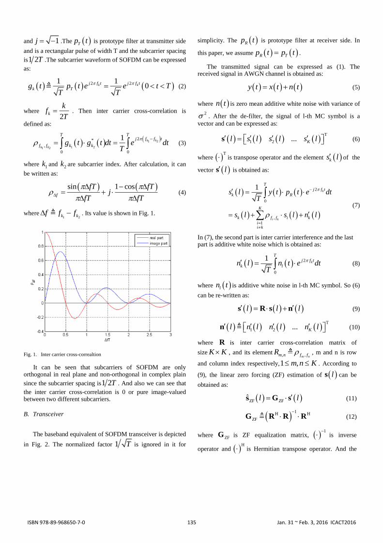
sin 1 cosf
fT fTj
fT fT
(4)
where1 2k kf f f . Its value is shown in Fig. 1.
Fig. 1. Inter carrier cross-correaltion
It can be seen that subcarriers of SOFDM are only orthogonal in real plane and non-orthogonal in complex plain
since the subcarrier spacing is1 2T . And also we can see that
the inter carrier cross-correlation is 0 or pure image-valued between two different subcarriers.
B. Transceiver
The baseband equivalent of SOFDM transceiver is depicted
in Fig. 2. The normalized factor 1 T is ignored in it for
simplicity. The Rp t is prototype filter at receiver side. In
this paper, we assume R Tp t p t .
The transmitted signal can be expressed as (1). The received signal in AWGN channel is obtained as:
y t x t n t (5)
where n t is zero mean additive white noise with variance of
2 . After the de-filter, the signal of l-th MC symbol is a
vector and can be expressed as:
T
1 2 ... Kl s l s l s l s (6)
where T
is transpose operator and the element ks l of the
vector ls is obtained as:
2
0
,
1
1k
i k
T
j f t
k R
K
k f f i k
ii k
s l y t p t e dtT
s l s l n l
(7)
In (7), the second part is inter carrier interference and the last part is additive white noise which is obtained as:
2
0
1k
T
j f t
k ln l n t e dtT
(8)
where ln t is additive white noise in l-th MC symbol. So (6)
can be re-written as:
l l l s R s n (9)
T
1 2 ... Kl n l n l n l n (10)
where R is inter carrier cross-correlation matrix of
size K K , and its element , ,m nm n f fR , m and n is row
and column index respectively,1 ,m n K . According to
(9), the linear zero forcing (ZF) estimation of ls can be
obtained as:
ZF ZFˆ l l s G s (11)
1
H H
ZF
G R R R (12)
where ZFG is ZF equalization matrix, 1
is inverse
operator and H
is Hermitian transpose operator. And the
135ISBN 978-89-968650-7-0 Jan. 31 ~ Feb. 3, 2016 ICACT2016

linear minimum mean square error (MMSE) estimation can be obtained as:
MMSE MMSEˆ l l s G s (13)
2
MMSEˆarg min E l l
G
G s s (14)
where E is mathematical expectation function and
MMSEG is linear MMSE equalization matrix. The solution of
(12) can be expressed as:
1
H 2 H
MMSE
G R R R R (15)
Please note:
H 2E l l n n R (16)
It should be noted that both linear ZF and MMSE
equalization algorithm require R is a full-rank matrix. However, this condition is not always satisfied for all the
possible value of total subcarrier number K. If R is not a full-rank matrix, to obtain a linear equalization, we have to set m
mute subcarriers, K m I , where I is the rank of the
matrix R . As we have pointed out in section I, the SOFDM is orthogonal in real field. So if subcarrier data symbols are all
real-valued, ˆ ls can be simply obtained as:
ˆ Rel ls s (17)
where Re denotes real part. For complex-valued
subcarrier symbols, the equalization is always necessary but the linear equalization will amplify the additive white noise power so that SOFDM will still suffer performance loss compared to OFDM which is ICI free. So we will propose a special scheme of SOFDM to improve the performance based on the property of SOFDM’s inter carrier correlation matrix.
Fig. 2. SOFDM transceiver
III. COMPLEMENTARY SOFDM
The property of R is very important to SOFDM. One useful property is:
T * 2 R R R R I (18)
where I is the unit matrix. This implies that if we can design a multi-carrier system whose inter carrier cross-correlation
matrix is T
R and combine its received signal with that of
SOFDM, the inter carrier interference (ICI) will be completely removed. We call this system complementary SOFDM. It has two parts: original part and complementary part. The former one is described in sector II which has an inter carrier
correlation matrix of R and the latter one has an inter carrier
correlation matrix ofT
R . These two parts occupy orthogonal resources (in time or frequency domain) and carry the identical data symbols in each subcarrier. There are a lot of methods to construct the commentary part. We will introduce one simple design in this section.
A. Transceiver
The only difference between original part and complementary part of complementary SOFDM is prototype filters. For complementary part, the prototype-filter is:
11 , 0
0,
k
c
k
t Tp t
otherwise
(19)
where k is subcarrier index, 1 k K , K is total subcarrier
number. Please note that prototype filter is identical at both transmitter and receiver side. The subcarrier waveform can be obtained as:
1
210k
k
j f tc
kg t e t TT
(20)
Then the inter carrier cross-correlation is:
1 2
1 2
1 2
2
,
0
1k k
k k
k k Tj f f tc
f f e dtT
(21)
where 1k and 2k are subcarrier index. The relationship
between 1 2
,k kf f and1 2
,k k
c
f f can be expressed as:
1 2
1 2
1 2 2 1
, 1 2
,
, ,
0,
,
k k
k k
k k k k
f fc
f f
f f f f
k k even
otherwise
(22)
Then we have:
c TR R (23)
wherec
R is inter carrier cross-correlation matrix of
complementary part, its element , ,m n
c c
m n f fR , m and n is
row and column index, 1 ,m n K . The signal of
complementary part is:
2
1
1k
Kj f tc c
k k
l k
x t s l p t l T eT
(24)
Similar to (9), after de-filter in AWGN channel, the signal of complementary part can be written as:
136ISBN 978-89-968650-7-0 Jan. 31 ~ Feb. 3, 2016 ICACT2016
Tc cl l l s R s n (25)
where c ln is white noise in l-th symbol of complementary
part of SOFDM after is de-filter. According to (9), (18), (23) and (25), we can have:
2c cl l l l l s s s n n (26)
Then we obtained an estimation of ls without ICI. So
equalization becomes unnecessary for complementary SOFDM.
Based on (26), we can design the complementary SOFDM as in Fig. 3. It is a group-wise system, each group is divided into original and complementary part and there are L multi-
carrier symbols in each part 1L . Two parts carry the
identical subcarrier data symbol ls where l is MC symbol
index 1 l L . The group index is ignored for simplicity.
And “symbol” in Fig. 3 stands for “multi-carrier symbol”.
Symbol 1 Symbol 2 … Symbol L Symbol 1 Symbol 2 … Symbol L
De-filter De-filter … De-filter De-filter De-filter … De-filter
...
... ...
original part complementary part
ˆ 1s ˆ 2s ˆ Ls
transmitter
receiver
time
...
Fig. 3. Complementary SOFDM
Compared with SOFDM, complementary SOFDM can perfectly cancel ICI without loss of performance but it doesn’t have spectral efficiency gain over OFDM since it needs doubled time resource than SOFDM. However, time diversity gain can be expected in this system if original and complementary parts experiences independent channel fading.
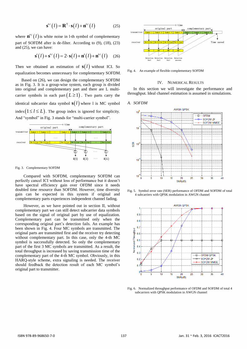
However, as we have pointed out in section II, without complementary part we can still detect subcarrier data symbols based on the signal of original part by use of equalization. Complementary part can be transmitted only when the corresponding original part’s detection fails. An example has been shown in Fig. 4. Four MC symbols are transmitted. The original parts are transmitted first and the receiver try detecting without complementary part. In this case, only the 4-th MC symbol is successfully detected. So only the complementary part of the first 3 MC symbols are transmitted. As a result, the total throughput is increased by saving transmission time of the complementary part of the 4-th MC symbol. Obviously, in this HARQ-style scheme, extra signaling is needed. The receiver should feedback the detection result of each MC symbol’s original part to transmitter.
Symbol 1 Symbol 2 Symbol 3 Symbol 4 Symbol 1 Symbol 2 Symbol 3
De-filter De-filter De-filter De-filter
original part complementary part
transmitter
receiver
time
EQ EQ EQ EQ
Detection success
Detection fail
Detection fail
Detection fail
Time saved
Fig. 4. An example of flexible complementary SOFDM
IV. NUMERICAL RESULTS
In this section we will investigate the performance and throughput. Ideal channel estimation is assumed in simulations.
A. SOFDM
Fig. 5. Symbol error rate (SER) performance of OFDM and SOFDM of total
4 subcarriers with QPSK modulation in AWGN channel
Fig. 6. Normalized throughput performance of OFDM and SOFDM of total 4
subcarriers with QPSK modulation in AWGN channel
137ISBN 978-89-968650-7-0 Jan. 31 ~ Feb. 3, 2016 ICACT2016
It can be seen from Fig. 5 that SOFDM performance is worse than OFDM since ICI is introduced in SOFDM by non-orthogonality. And MMSE performance is better than ZF for SOFDM. This is because MMSE can suppress the effect of white noise power amplification of ZF. In Fig. 6, given the same total subcarrier, normalized throughput is evaluated for SOFDM and OFDM. OFDM throughput is higher than SOFDM in low SNR cases but in high SNR cases, SOFDM throughput is beyond OFDM for halved bandwidth over OFDM.
B. Complementary SOFDM
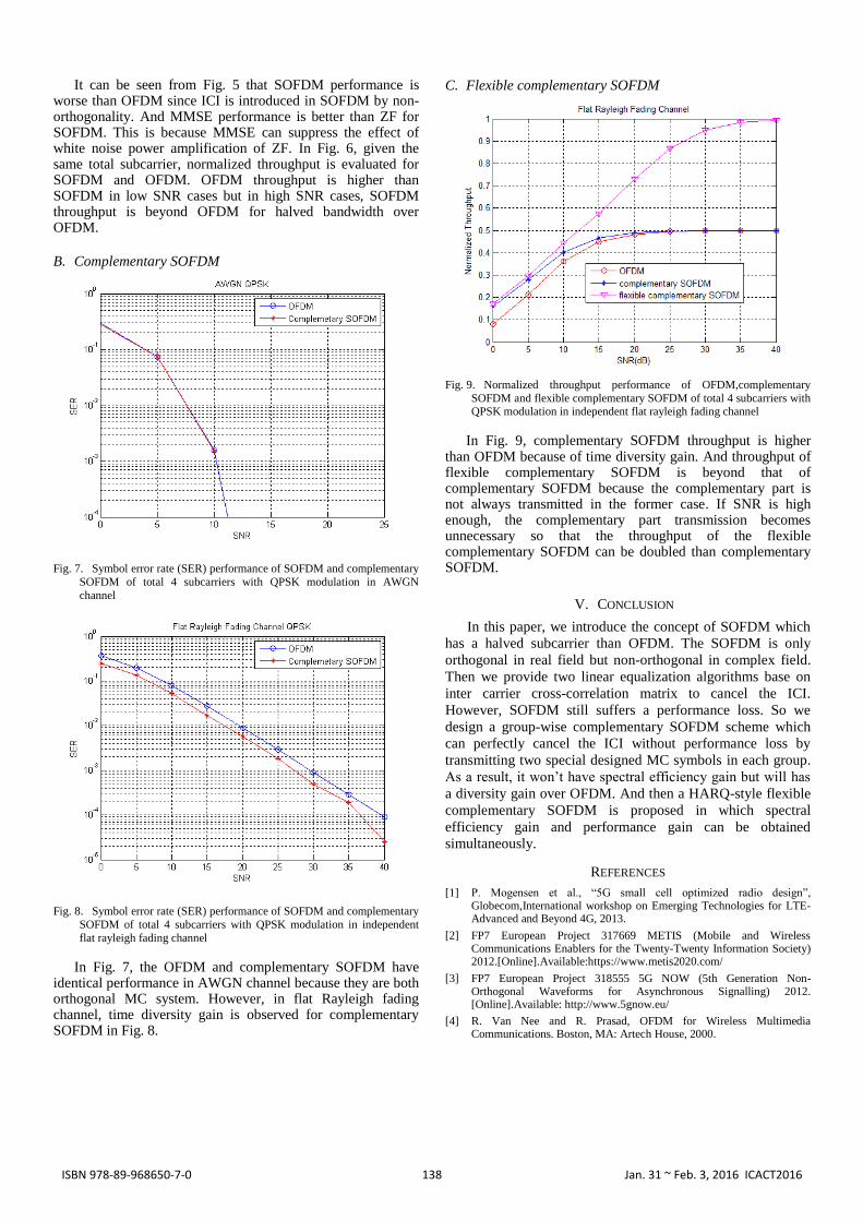
Fig. 7. Symbol error rate (SER) performance of SOFDM and complementary
SOFDM of total 4 subcarriers with QPSK modulation in AWGN
channel
Fig. 8. Symbol error rate (SER) performance of SOFDM and complementary
SOFDM of total 4 subcarriers with QPSK modulation in independent
flat rayleigh fading channel
In Fig. 7, the OFDM and complementary SOFDM have identical performance in AWGN channel because they are both orthogonal MC system. However, in flat Rayleigh fading channel, time diversity gain is observed for complementary SOFDM in Fig. 8.
C. Flexible complementary SOFDM
Fig. 9. Normalized throughput performance of OFDM,complementary
SOFDM and flexible complementary SOFDM of total 4 subcarriers with QPSK modulation in independent flat rayleigh fading channel
In Fig. 9, complementary SOFDM throughput is higher than OFDM because of time diversity gain. And throughput of flexible complementary SOFDM is beyond that of complementary SOFDM because the complementary part is not always transmitted in the former case. If SNR is high enough, the complementary part transmission becomes unnecessary so that the throughput of the flexible complementary SOFDM can be doubled than complementary SOFDM.
V. CONCLUSION
In this paper, we introduce the concept of SOFDM which
has a halved subcarrier than OFDM. The SOFDM is only
orthogonal in real field but non-orthogonal in complex field.
Then we provide two linear equalization algorithms base on
inter carrier cross-correlation matrix to cancel the ICI.
However, SOFDM still suffers a performance loss. So we
design a group-wise complementary SOFDM scheme which
can perfectly cancel the ICI without performance loss by
transmitting two special designed MC symbols in each group.
As a result, it won’t have spectral efficiency gain but will has
a diversity gain over OFDM. And then a HARQ-style flexible
complementary SOFDM is proposed in which spectral
efficiency gain and performance gain can be obtained
simultaneously.
REFERENCES
[1] P. Mogensen et al., “5G small cell optimized radio design”, Globecom,International workshop on Emerging Technologies for LTE-Advanced and Beyond 4G, 2013.
[2] FP7 European Project 317669 METIS (Mobile and Wireless Communications Enablers for the Twenty-Twenty Information Society) 2012.[Online].Available:https://www.metis2020.com/
[3] FP7 European Project 318555 5G NOW (5th Generation Non-Orthogonal Waveforms for Asynchronous Signalling) 2012. [Online].Available: http://www.5gnow.eu/
[4] R. Van Nee and R. Prasad, OFDM for Wireless Multimedia Communications. Boston, MA: Artech House, 2000.
138ISBN 978-89-968650-7-0 Jan. 31 ~ Feb. 3, 2016 ICACT2016
[5] Y. Li and G. L . Stüber, Eds., Orthogonal Frequency Division Multiplexing for Wireless Communications. New York, NY: Springer-Verlag, 2006.
[6] Behrouz Farhang-Boroujeny, OFDM versus Filter Bank Multicarrier,IEEE SIGNAL PROCESSING MAGAZINE,MAY 2011,pp.92-112.
[7] P. Siohan, C. Siclet, and N. Lacaille, “Analysis and Design of FDM/OQAM Systems Based on Filterbank Theory,” IEEE Transactions on Signal Processing, vol. 50, no. 5, pp. 1170-1183, August 2002.
[8] P. Siohan, and N. Lacaille, “Analysis of OFDM/OQAM Systems Based on the Filterbank Theory,” IEEE Global Telecommunications Conference, Rio de Janeiro, Brazil, December 1999.
[9] B. Farhang-Boroujeny, “OFDM Versus Filter Bank Multicarrier,” IEEE Signal Processing Magazine, vol. 28, no. 3, pp. 92-112, May 2011.
[10] R. Zakaria, and D. Le Ruyet, “A Novel Filter-Bank Multicarrier Scheme to Mitigate the Intrinsic Interference: Application to MIMO Systems,”IEEE Transactions on Wireless Communications, vol. 11, no. 3, pp.1112-1123, March 2012.
[11] M. Bellanger, "Physical layer for future broadband radio systems," Radio and Wireless Symposium (RWS), pp.436-439, 10-14 Jan. 2010.
[12] L. G. Baltar, D. S. Waldhauser, and J. A. Nossek, “Out-of-band radiation in multicarrier systems: A comparison,” in Proc. Multi-Carrier Spread Spectrum Lecture Notes Elect. Eng., Jun. 2007, vol. 1, pp.107–116.
[13] H. Nam, M. Choi, C. Kim, D. Hong, and S. Choi, “A new filterbank multicarrier system for qam signal transmission and receiption,”in International Conference on Communications (ICC), 2014 IEEE, pp.1–6, June 2014.
[14] Paolo Banelli, Stefano Buzzi, Giulio Colavolpe, Andrea Modenini,Fredrik Rusek, and Alessandro Ugolini, "Modulation Formats and Waveforms for 5G Networks: Who Will Be the Heir of
OFDM?",IEEE SIGNAL PROCESSING MAGAZINE,November 2014,pp.80-93.
[15] Wonsuk Chung, Beomju Kim, Moonchang Choi, Hyungju Nam, Hyunkyu Yu, Sooyoung Choi,and Daesik Hong,"Synchronization Error in QAM-based FBMC System",2014 IEEE Military Communications Conference,pp.699-705.
[16] M. Bellanger et al., “Fbmc physical layer: a primer,” PHYDYAS,January, 2010.
[17] R. W. Chang, “Synthesis of band-limited orthogonal signals for multichannel data transmission,” Bell System Tech. J., vol. 45, pp. 1775–1796, July 1966.
[18] B. R. Saltzberg, “Performance of an efficient parallel data transmission system,”IEEE Trans. Commun. Technol., vol. 15, no. 6, pp. 805–811, Dec. 1967.
Yang Fan was born in 1979 in Hubei province in China.
He acquired his PHD of signal and information processing at Beijing University of Post and
Telecommunication in the city of Beijing (China) in
2007. He served in Fujitsu R&D Center Co., Ltd (FRDC). His major interests include 5G wireless
communication, waveform, multiple access technology,
channel coding.
Wang Xin was born in Tianjin, China in 1971. He received Ph.D. degree from Tianjin University, China, in
2005. He has been with Fujitsu R&D Center Co., Ltd
(FRDC) since 2005. He is currently heading the group for 5G study in FRDC’s Communication Lab. His recent
research interests include wireless signal processing with
emphasis on 5G new RAT and 3GPP standardization.
139ISBN 978-89-968650-7-0 Jan. 31 ~ Feb. 3, 2016 ICACT2016