A novel method ML SCI-2
4
A novel method for the processing of carbon foam containing in situ grown nano-materials and silicon nanowires Shameel Farhan n , Rumin Wang, Hao Jiang Department of Applied Chemistry School of Science, NWPU, Xi’an 710072, China article info Article history: Received 21 April 2015 Received in revised form 1 July 2015 Accepted 12 July 2015 Available online 14 July 2015 Keywords: Carbon materials Porous materials Microstructure Nanocomposites abstract A novel method for the processing of carbon foam has been developed by using a powder mixture containing polyurethane foam and novolac resin hereafter called PN. Various additives like Si, Al, FeCl 3 , activated carbon (AC), short-carbon fibers (SCF) were mixed individually or in combination, carbonized under coal and analyzed for density, microstructure and compressive strength. The pore morphology changed significantly by using different kinds of additives. SCFs were effectively mixed and bonded within the pore walls. Si converted in situ into silicon carbide and a jungle of kinked and twisted na- nowires all around the pores. CNTs with amorphous carbon beads were observed throughout the pore surfaces when 10 wt% FeCl 3 was added. Al increased the compressive strength when used upto 6 wt%. & 2015 Elsevier B.V. All rights reserved. 1. Introduction Carbon foams are rigid and porous materials, which exhibit a unique characteristic of tailorability in physical, thermal and functional properties [1]. There are several types, depending on the raw materials, process parameters and the production method [2,3]. The most important categories are non-graphitic and gra- phite foam apart from the reticulated vitreous carbon and the most recently developed biomass-based carbon foams [4]. Despite first development in 1960s by W. Ford [5], the scientists at AFRL Dayton OH [6] started the major break-through in 1990s after the development of pitch-based foam. The processing of bulk carbon foam is not an easy task and major challenges are encountered when various additives/fillers are mixed during production [7]. This letter focuses on the development of a novel method for carbon foam production with added features of mixing various additives/fillers and in situ grown nano-reinforcements. The car- bon foam with added features of nano-reinforcements and fillers can be utilized as thermal insulating material, anti-oxidative and anti-ablative compound, radar absorbing structure, catalyst sup- port, reinforcement material and next-generation high-perfor- mance electronic and energy storage component. No reports are available in which carbon foam has been prepared with in situ grown nanowires simultaneously. Recently, carbon foam has been prepared using graphitic and non-graphitic carbon precursors with a soft template [8]. Phenolic resin containing pitch and alu- minum (Al) powders was used to impregnate an open cell poly- urethane foam. In an attempt to increase the amount of Al, this powder method has been emerged. To further validate this pro- cess, various other fillers/additives like silicon (Si), silver (Ag), activated carbon, (AC) and short-carbon fibers (SCFs) were used as a test case and integrated into the foam structure in the form of bonded or in situ compounds. Compressive strength was also found as a complementary study. 2. Experimental Semi-rigid PU foam, novolac resin, Al powder, Si powder, SCFs and AC were purchased from Sinopharm Chemicals, Beijing China. Ag paper, as traditionally used on sweets in Pakistan, was pur- chased from the market. In Ref. [8], resole resin was used as carbon precursor and in an attempt to add more quantity of Al, many trials were made to get homogenized and stabilized green foam. The problem became more severe after curing due to the differ- ence in mass mobility and wettability in the PU foam. Novolac solved this issue when it was used instead of resole, as it is an amorphous solid. Dissolved novolac was poured on a piece of PU foam and kept at 25 °C for 24 h after which it became hard and easily crushed into powdered form. It was named foam novolac (FN) instant precursor and further ground with other fillers/ad- ditives individually or in a combination. A FN containing 40 wt% PU and 60 wt% novolac, denoted as F 4 N 6 , was ball-milled with additives/fillers using a QM-1SP2 planetary-type machine. The Contents lists available at ScienceDirect journal homepage: www.elsevier.com/locate/matlet Materials Letters http://dx.doi.org/10.1016/j.matlet.2015.07.060 0167-577X/& 2015 Elsevier B.V. All rights reserved. n Corresponding author. Fax: þ86 29 88492943. E-mail addresses: [email protected] (S. Farhan), [email protected] (R. Wang). Materials Letters 159 (2015) 439–442
-
Upload
shameel-farhan -
Category
Documents
-
view
99 -
download
0
Transcript of A novel method ML SCI-2

Materials Letters 159 (2015) 439–442
Contents lists available at ScienceDirect
Materials Letters
http://d0167-57
n CorrE-m
rmwang
journal homepage: www.elsevier.com/locate/matlet
A novel method for the processing of carbon foam containing in situgrown nano-materials and silicon nanowires
Shameel Farhan n, Rumin Wang, Hao JiangDepartment of Applied Chemistry School of Science, NWPU, Xi’an 710072, China
a r t i c l e i n f o
Article history:Received 21 April 2015Received in revised form1 July 2015Accepted 12 July 2015Available online 14 July 2015
Keywords:Carbon materialsPorous materialsMicrostructureNanocomposites
x.doi.org/10.1016/j.matlet.2015.07.0607X/& 2015 Elsevier B.V. All rights reserved.
esponding author. Fax: þ86 29 88492943.ail addresses: [email protected] (S. [email protected] (R. Wang).
a b s t r a c t
A novel method for the processing of carbon foam has been developed by using a powder mixturecontaining polyurethane foam and novolac resin hereafter called PN. Various additives like Si, Al, FeCl3,activated carbon (AC), short-carbon fibers (SCF) were mixed individually or in combination, carbonizedunder coal and analyzed for density, microstructure and compressive strength. The pore morphologychanged significantly by using different kinds of additives. SCFs were effectively mixed and bondedwithin the pore walls. Si converted in situ into silicon carbide and a jungle of kinked and twisted na-nowires all around the pores. CNTs with amorphous carbon beads were observed throughout the poresurfaces when 10 wt% FeCl3 was added. Al increased the compressive strength when used upto 6 wt%.
& 2015 Elsevier B.V. All rights reserved.
1. Introduction
Carbon foams are rigid and porous materials, which exhibit aunique characteristic of tailorability in physical, thermal andfunctional properties [1]. There are several types, depending onthe raw materials, process parameters and the production method[2,3]. The most important categories are non-graphitic and gra-phite foam apart from the reticulated vitreous carbon and themost recently developed biomass-based carbon foams [4]. Despitefirst development in 1960s by W. Ford [5], the scientists at AFRLDayton OH [6] started the major break-through in 1990s after thedevelopment of pitch-based foam. The processing of bulk carbonfoam is not an easy task and major challenges are encounteredwhen various additives/fillers are mixed during production [7].This letter focuses on the development of a novel method forcarbon foam production with added features of mixing variousadditives/fillers and in situ grown nano-reinforcements. The car-bon foam with added features of nano-reinforcements and fillerscan be utilized as thermal insulating material, anti-oxidative andanti-ablative compound, radar absorbing structure, catalyst sup-port, reinforcement material and next-generation high-perfor-mance electronic and energy storage component. No reports areavailable in which carbon foam has been prepared with in situgrown nanowires simultaneously. Recently, carbon foam has beenprepared using graphitic and non-graphitic carbon precursors
arhan),
with a soft template [8]. Phenolic resin containing pitch and alu-minum (Al) powders was used to impregnate an open cell poly-urethane foam. In an attempt to increase the amount of Al, thispowder method has been emerged. To further validate this pro-cess, various other fillers/additives like silicon (Si), silver (Ag),activated carbon, (AC) and short-carbon fibers (SCFs) were used asa test case and integrated into the foam structure in the form ofbonded or in situ compounds. Compressive strength was alsofound as a complementary study.
2. Experimental
Semi-rigid PU foam, novolac resin, Al powder, Si powder, SCFsand AC were purchased from Sinopharm Chemicals, Beijing China.Ag paper, as traditionally used on sweets in Pakistan, was pur-chased from the market. In Ref. [8], resole resin was used as carbonprecursor and in an attempt to add more quantity of Al, manytrials were made to get homogenized and stabilized green foam.The problem became more severe after curing due to the differ-ence in mass mobility and wettability in the PU foam. Novolacsolved this issue when it was used instead of resole, as it is anamorphous solid. Dissolved novolac was poured on a piece of PUfoam and kept at 25 °C for 24 h after which it became hard andeasily crushed into powdered form. It was named foam novolac(FN) instant precursor and further ground with other fillers/ad-ditives individually or in a combination. A FN containing 40 wt%PU and 60 wt% novolac, denoted as F4N6, was ball-milled withadditives/fillers using a QM-1SP2 planetary-type machine. The

Fig. 1. Processing of carbon foam; (a) powdered-precursor, (b) molding, (c) curing, (d) green foam and (e) carbonized foam.
S. Farhan et al. / Materials Letters 159 (2015) 439–442440
final mixtures denoted by A, B, C, D, E, F and G were molded undera slight pressure, cured and carbonized while buried under coaland N2 flow. Further details can be found in [8]. Fig. 1 shows thevarious stages of processing prototype samples. Density wasmeasured by ratio of mass to the total apparent volume. The SEMimages were carried out using a JEOL (model JSM-6610LV) scan-ning electron microscope equipped by an energy dispersive X-rayanalyzer Compressive strength of 10 mm�10 mm�10 mm sam-ples was measured by the Instron-3369 UTM.
3. Results and discussion
Physical properties and surface morphology of various proto-type samples are shown in Table 1 and Figs. 2–4 respectively.Additional information regarding porosity, pore volume and in-cremental pore size distribution is given in S1. Open-cell structureis seen in all the pictures with irregular, uneven and rough mor-phology. Due to the complexity and randomness in the pore shape,pore sizes fall between a range upto 500 μm, although some poresare seen broken due to cutting and grinding The carbon foampossesses well-developed pore structures with a bulk density of0.55–0.69 g/cm3, and there are no obvious micro-cracks on thewalls. Fig. 2(a and b) shows the sample A where the pore wallthickness is also not the same and varies between 10 and 100 μm.This was due to the largest shrinkage of PU and novolac in thecarbon foam containing no additive/fillers. It is quite evident thatAC increased the roughness of pores and the original cellular-structure of the biomass was largely maintained albeit in thesample B. Some part of 200–400 μm long carbon fiber existed inthe ligament and the remaining was exposed outside in thesample C with 5% SCFs. The SCFs are seen well dispersed and wellbonded with the walls of carbon foam without cracks and de-bondings. In Fig. 3, the resulting spectra show that Al metal alongwith carbon, nitrogen and oxygen was detected in the inspection
Table 1Physical properties of carbon foam: composition, density, porosity, open pore volume a
Sample ID Description Fillers/additive
Bulk density (g/cm3) True density (g/cm3
A (F4N6) No filler 0.55 1.65B (F4N6)80(AC)20 20%AC 0.56 1.77C (F4N6)95(SCF)05 05%SCF 0.59 1.82D (F4N6)94(Al)06 06%Al 0.59 1.87E (F4N6)97(Ag)03 03%Ag 0.55 1.67F (F4N6)90(FeCl3)10 10% FeCl3 0.59 1.91G (F4N6)80(Si)20 20%Si 0.69 2.06
field. Ag and Al were well dispersed in the samples and someagglomerated particles with outer surface either smooth or cov-ered with some nanoparticles, most probably some oxy-carbidesand nitrides (EDX results), were also visible (Figs. S2–S5). Thenano-fibers and particles of about 100 nm diameter fully coveredthe Al particles with random orientations. Due to addition of FeCl3,CNTs with amorphous beads were grown homogeneously in thepores of sample F as in Fig. 4(a and b). The appearance of thesebeads was suggestive of solidification of super-cooled liquid dro-plets. Small beads were aligned to form fishbone-shaped tubeswith knots and necks approximately at equal distances betweenthem. Some CNTs were 45 nm in diameter and others were grownupto huge diameters, upto 0.8 μm, with bending and sharp elbowlike morphology.
Fig. 4(c and d) shows the sample G containing Si which wasconverted in situ into nanowires. The clump that looks tangled upis actually many Si nanowires that are difficult to distinguish andsome of them fuse together into thicker structures. Among thejungle of kinked and curly wires, several very straight wires withsmaller diameter were formed. The nanowires with 20–40 nmdiameters have been observed but there are also some large wireswith 400–600 nm diameters. X-ray diffraction scan also confirmthe formation of SiC along with some residual Si (Fig. S6). In thiswork, the gases (CO, CO2, H2, N2 and CH4), high-temperature(1000 °C), close-space (coal), and the slow-cooling rate are keyfactors for Si nanowires formation. The protective gases and hightemperature met the condition for formation of SiO and CO; theclosed space increased the concentration of SiO and CO mixedgases; and slow-cooling rate provided an interval for the genera-tion of nanowires. Furthermore, the cellular template has enoughflow space for the mass transport of the gaseous species (SiO andCO). Compressive strength of carbon foam is closely related tomicrostructure, amount of additives/fillers and in situ compounds.The sample D containing 6 wt% Al showed the highest value ofspecific strength as shown in Table 1. The fact indicates that the
nd compressive strength.
) Open por-osity (%)
Open porevolume(cm3/g)
Compressivestrength (MPa)
Specific strength (MPa-cm3/g)
66.67 1.21 18 32.768.36 1.22 15 26.867.58 1.15 25 42.468.44 1.16 32 54.067.06 1.22 28 51.069.10 1.17 25 42.466.50 0.96 17 24.6

Fig. 2. Morphology of carbon foam; (a) low-density, (b) high-density, (c) with 10%AC and (d) with 5%SCFs.
Fig. 3. Surface morphology of carbon foam; (a, b) with Ag and (c, d) with Al.
S. Farhan et al. / Materials Letters 159 (2015) 439–442 441
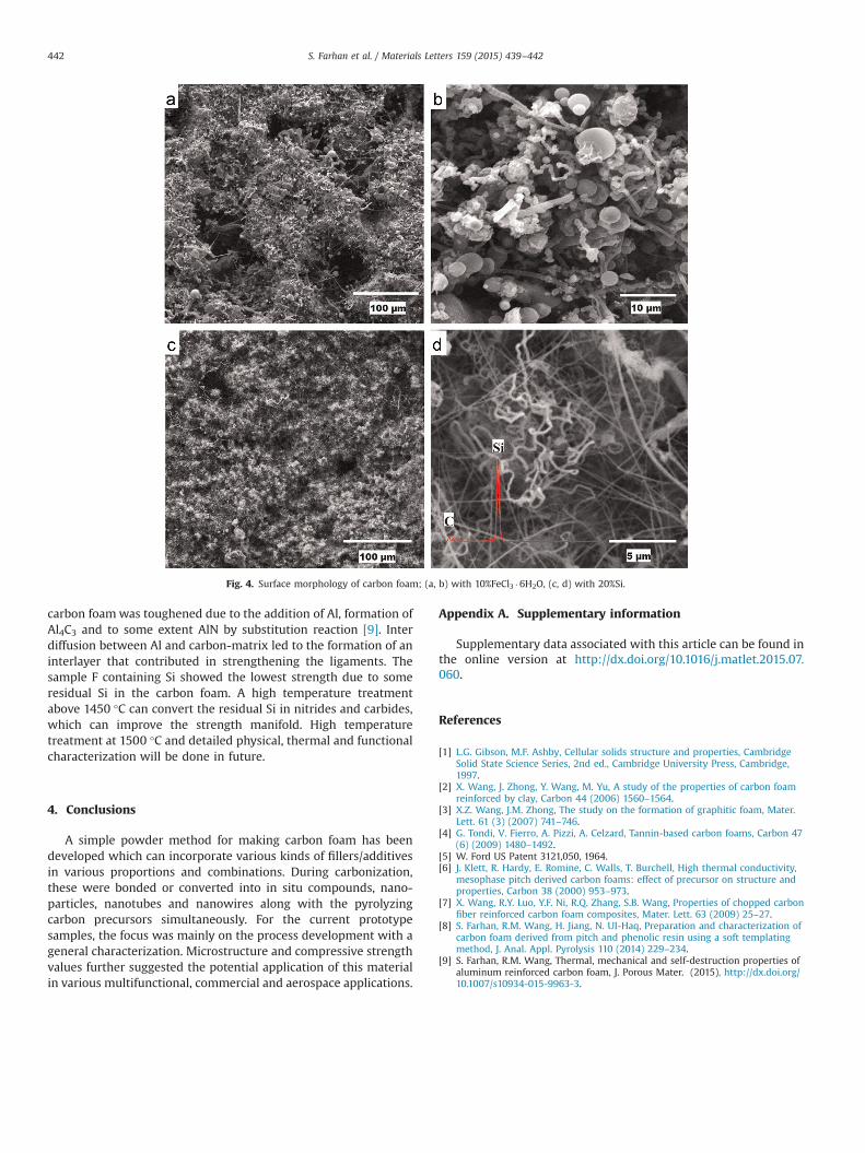
Fig. 4. Surface morphology of carbon foam; (a, b) with 10%FeCl3 �6H2O, (c, d) with 20%Si.
S. Farhan et al. / Materials Letters 159 (2015) 439–442442
carbon foamwas toughened due to the addition of Al, formation ofAl4C3 and to some extent AlN by substitution reaction [9]. Interdiffusion between Al and carbon-matrix led to the formation of aninterlayer that contributed in strengthening the ligaments. Thesample F containing Si showed the lowest strength due to someresidual Si in the carbon foam. A high temperature treatmentabove 1450 °C can convert the residual Si in nitrides and carbides,which can improve the strength manifold. High temperaturetreatment at 1500 °C and detailed physical, thermal and functionalcharacterization will be done in future.
4. Conclusions
A simple powder method for making carbon foam has beendeveloped which can incorporate various kinds of fillers/additivesin various proportions and combinations. During carbonization,these were bonded or converted into in situ compounds, nano-particles, nanotubes and nanowires along with the pyrolyzingcarbon precursors simultaneously. For the current prototypesamples, the focus was mainly on the process development with ageneral characterization. Microstructure and compressive strengthvalues further suggested the potential application of this materialin various multifunctional, commercial and aerospace applications.
Appendix A. Supplementary information
Supplementary data associated with this article can be found inthe online version at http://dx.doi.org/10.1016/j.matlet.2015.07.060.
References
[1] L.G. Gibson, M.F. Ashby, Cellular solids structure and properties, CambridgeSolid State Science Series, 2nd ed., Cambridge University Press, Cambridge,1997.
[2] X. Wang, J. Zhong, Y. Wang, M. Yu, A study of the properties of carbon foamreinforced by clay, Carbon 44 (2006) 1560–1564.
[3] X.Z. Wang, J.M. Zhong, The study on the formation of graphitic foam, Mater.Lett. 61 (3) (2007) 741–746.
[4] G. Tondi, V. Fierro, A. Pizzi, A. Celzard, Tannin-based carbon foams, Carbon 47(6) (2009) 1480–1492.
[5] W. Ford US Patent 3121,050, 1964.[6] J. Klett, R. Hardy, E. Romine, C. Walls, T. Burchell, High thermal conductivity,
mesophase pitch derived carbon foams: effect of precursor on structure andproperties, Carbon 38 (2000) 953–973.
[7] X. Wang, R.Y. Luo, Y.F. Ni, R.Q. Zhang, S.B. Wang, Properties of chopped carbonfiber reinforced carbon foam composites, Mater. Lett. 63 (2009) 25–27.
[8] S. Farhan, R.M. Wang, H. Jiang, N. UI-Haq, Preparation and characterization ofcarbon foam derived from pitch and phenolic resin using a soft templatingmethod, J. Anal. Appl. Pyrolysis 110 (2014) 229–234.
[9] S. Farhan, R.M. Wang, Thermal, mechanical and self-destruction properties ofaluminum reinforced carbon foam, J. Porous Mater. (2015), http://dx.doi.org/10.1007/s10934-015-9963-3.

![arXiv:1512.05461v2 [cond-mat.mtrl-sci] 7 Jan 2016 · arXiv:1512.05461v2 [cond-mat.mtrl-sci] 7 Jan 2016 A Novel Material for In Situ Construction on Mars: Experiments and Numerical](https://static.fdocuments.net/doc/165x107/5fb1d708774d617c246e9d81/arxiv151205461v2-cond-matmtrl-sci-7-jan-2016-arxiv151205461v2-cond-matmtrl-sci.jpg)