A Novel Fold-Based Design Approach toward Printable Soft ...
13
FULL PAPER 1700172 (1 of 12) © 2017 WILEY-VCH Verlag GmbH & Co. KGaA, Weinheim www.advmattechnol.de A Novel Fold-Based Design Approach toward Printable Soft Robotics Using Flexible 3D Printing Materials Benjamin Wee Keong Ang and Raye Chen Hua Yeow* DOI: 10.1002/admt.201700172 bodies. [10] This makes soft robots the ideal candidate for rehabilitative devices. [11] Among the many types of soft actua- tors, the scope of application of fluidic actuators includes locomotion, [12–14] manipulation, [1,15] as well as wearables for medical applications. [16–18] These actuators are primarily fabricated through mold- casting of elastomeric materials, typi- cally silicone rubber. This mold-casting technique is cumbersome and gener- ally involves manual processing after the actuator is cured, including the weaving of fibers around the actuator [19] or attaching a piece of strain limiting layer [20,21] to the base of the actuator. In a recent study, Yap et al. [22] presented a pneumatic actu- ator fabricated using fused deposition modeling (FDM) technology. Compared to mold-casting techniques and high-end multimaterial 3D printing, FDM using a consumer-grade 3D printer is a more cost- effective, automated, and simple method of soft robotics fabrication, prompting easier adoption by researchers and hobbyists. The application of 3D printing tech- niques allows for more complex designs of pneumatic actua- tors that can hence yield higher force output, and achieve more sophisticated bending profiles. This paper presents a novel fold-based design of a 3D-printed soft pneumatic bending actuator. The main advantages of 3D-printed soft pneumatic actuators over other types involve the automation of the fabrication process and the high attain- able mechanical performance, which is comparable or perhaps superior to that of conventional actuator types. This fabrication method also allows for variations to the design of the actuator that can hence achieve different bending profiles. Moreover, we demonstrate that the fold-based design is able to generate a high force output at a safe pneumatic pressure (<200 kPa, rec- ommended by Occupational Safety and Health Administration Standard 29 CFR 1910.242(b)). Finally, we present our key find- ings in (1) a 3D-printed fold-based actuator fabrication process, (2) actuator characterization, and (3) a design-centric approach toward different bending profiles for different applications. 2. Design Rationale The current design of bellow-type fluidic actuators [16,22] is observed to be inefficient in performing bending. Using a simplified mathematical model (Figure 1), it can be shown Soft robotic technologies have been known to have various advantages over their rigid counterparts due to their compliant and deformable proper- ties. They can carry out delicate object manipulation and perform complex maneuvers in confined spaces, which traditional robotics has difficulty with. The most widely adopted fabrication method for traditional soft elastomeric fluidic actuators is mold-casting, which is cumbersome and involves several manual steps. Therefore, a substantial variability in performance and quality of these actuators arises directly from the manufacturing process. This paper presents on a novel fold-based design of a 3D-printed soft pneumatic bending actuator. In contrast to other works that rely on high-end multimaterial 3D printers, a consumer-grade open source 3D printer to fabricate soft pneu- matic actuators in a fast and cheap way using fused deposition modeling technology has been adapted. This allows for consistency in both the quality of the actuators and their mechanical performance. The key findings in (1) a 3D-printed fold-based actuator fabrication process, (2) actuator characteriza- tion, and (3) a design-centric approach toward different bending profiles for different applications are presented. B. W. K. Ang, Prof. R. C. H. Yeow Department of Biomedical Engineering Faculty of Engineering National University of Singapore Block E4, #04-08, 4 Engineering Drive 3, Singapore 117583, Singapore E-mail: [email protected] The ORCID identification number(s) for the author(s) of this article can be found under https://doi.org/10.1002/admt.201700172. 3D-Printed Soft Robotics 1. Introduction Soft actuators have been at the core of many soft robotic tech- nologies like robotic grippers, [1–4] surgical systems, [3,4] assis- tive and rehabilitation exoskeletons. [5–7] The main advantage of soft robotic technology over their rigid counterparts lies within their compliant and deformable nature. In fact, this intrinsic property allows soft actuators to achieve multiple degrees of freedom (DOF), presenting useful capabilities in a variety of applications. For example, soft robots can carry out delicate object manipulation [8] minimizing the risk of damage to the object. They can also maneuver comfortably in confined spaces due to their ability to squeeze into tight spaces, [9] which enables them to reach into places where rigid bodies cannot. Furthermore, not only do soft actuators have the potential for natural joint movements during rehabilitation but also their compliance can provide a safer form of interaction with rigid Adv. Mater. Technol. 2018, 3, 1700172
Transcript of A Novel Fold-Based Design Approach toward Printable Soft ...

FULL PAPER
1700172 (1 of 12) © 2017 WILEY-VCH Verlag GmbH & Co. KGaA, Weinheim
www.advmattechnol.de
A Novel Fold-Based Design Approach toward Printable Soft Robotics Using Flexible 3D Printing Materials
Benjamin Wee Keong Ang and Raye Chen Hua Yeow*
DOI: 10.1002/admt.201700172
bodies.[10] This makes soft robots the ideal candidate for rehabilitative devices.[11]
Among the many types of soft actua-tors, the scope of application of fluidic actuators includes locomotion,[12–14] manipulation,[1,15] as well as wearables for medical applications.[16–18] These actuators are primarily fabricated through mold-casting of elastomeric materials, typi-cally silicone rubber. This mold-casting technique is cumbersome and gener-ally involves manual processing after the actuator is cured, including the weaving of fibers around the actuator[19] or attaching a piece of strain limiting layer[20,21] to the base of the actuator. In a recent study, Yap et al.[22] presented a pneumatic actu-ator fabricated using fused deposition modeling (FDM) technology. Compared to mold-casting techniques and high-end multimaterial 3D printing, FDM using a consumer-grade 3D printer is a more cost-effective, automated, and simple method
of soft robotics fabrication, prompting easier adoption by researchers and hobbyists. The application of 3D printing tech-niques allows for more complex designs of pneumatic actua-tors that can hence yield higher force output, and achieve more sophisticated bending profiles.
This paper presents a novel fold-based design of a 3D-printed soft pneumatic bending actuator. The main advantages of 3D-printed soft pneumatic actuators over other types involve the automation of the fabrication process and the high attain-able mechanical performance, which is comparable or perhaps superior to that of conventional actuator types. This fabrication method also allows for variations to the design of the actuator that can hence achieve different bending profiles. Moreover, we demonstrate that the fold-based design is able to generate a high force output at a safe pneumatic pressure (<200 kPa, rec-ommended by Occupational Safety and Health Administration Standard 29 CFR 1910.242(b)). Finally, we present our key find-ings in (1) a 3D-printed fold-based actuator fabrication process, (2) actuator characterization, and (3) a design-centric approach toward different bending profiles for different applications.
2. Design Rationale
The current design of bellow-type fluidic actuators[16,22] is observed to be inefficient in performing bending. Using a simplified mathematical model (Figure 1), it can be shown
Soft robotic technologies have been known to have various advantages over their rigid counterparts due to their compliant and deformable proper-ties. They can carry out delicate object manipulation and perform complex maneuvers in confined spaces, which traditional robotics has difficulty with. The most widely adopted fabrication method for traditional soft elastomeric fluidic actuators is mold-casting, which is cumbersome and involves several manual steps. Therefore, a substantial variability in performance and quality of these actuators arises directly from the manufacturing process. This paper presents on a novel fold-based design of a 3D-printed soft pneumatic bending actuator. In contrast to other works that rely on high-end multimaterial 3D printers, a consumer-grade open source 3D printer to fabricate soft pneu-matic actuators in a fast and cheap way using fused deposition modeling technology has been adapted. This allows for consistency in both the quality of the actuators and their mechanical performance. The key findings in (1) a 3D-printed fold-based actuator fabrication process, (2) actuator characteriza-tion, and (3) a design-centric approach toward different bending profiles for different applications are presented.
B. W. K. Ang, Prof. R. C. H. YeowDepartment of Biomedical EngineeringFaculty of EngineeringNational University of SingaporeBlock E4, #04-08, 4 Engineering Drive 3, Singapore 117583, SingaporeE-mail: [email protected]
The ORCID identification number(s) for the author(s) of this article can be found under https://doi.org/10.1002/admt.201700172.
3D-Printed Soft Robotics
1. Introduction
Soft actuators have been at the core of many soft robotic tech-nologies like robotic grippers,[1–4] surgical systems,[3,4] assis-tive and rehabilitation exoskeletons.[5–7] The main advantage of soft robotic technology over their rigid counterparts lies within their compliant and deformable nature. In fact, this intrinsic property allows soft actuators to achieve multiple degrees of freedom (DOF), presenting useful capabilities in a variety of applications. For example, soft robots can carry out delicate object manipulation[8] minimizing the risk of damage to the object. They can also maneuver comfortably in confined spaces due to their ability to squeeze into tight spaces,[9] which enables them to reach into places where rigid bodies cannot. Furthermore, not only do soft actuators have the potential for natural joint movements during rehabilitation but also their compliance can provide a safer form of interaction with rigid
Adv. Mater. Technol. 2018, 3, 1700172

www.advancedsciencenews.com
© 2017 WILEY-VCH Verlag GmbH & Co. KGaA, Weinheim1700172 (2 of 12)
www.advmattechnol.de
that bellow-type actuators produce less bending as compared to fold-based designs. From the principle of conservation of energy, the work done by the pneumatic pressure is assumed to be entirely converted to strain energy which is stored in the elastic walls of the actuator (Equation (1)) with volume V, Young’s mod-ulus E, and resultant strain ε
1
22Fd VE ε=
(1)
Referring to Figure 1a and working from Equation (1), it can be shown in Equation (2) that the degree of unfolding d in a fold-based bending actuator, as well as the magnitude of strain ΔL1, is dependent on the Young’s mod-ulus E of the elastomeric material and the force F exerted by the pneumatic pressure on the walls of the actuator
212
12
d
L
VE
L F( )∆=
(2)
Figure 1b illustrates that for the same elas-tomeric material and pneumatic pressure, a bellow-type actuator will experience deforma-tion at the base of the actuator. The curvature due to the asymmetrical strain is hence
Ratio of top strain to bottom strain 1 1
2 2
L L
L L= + ∆
+ ∆ (3)
On the other hand, since the strain limi-ting layer does not experience a pneumatic pressure and is assumed to be inextensible, the curvature in the fold-based design is calculated to be
Ratio of top strain to bottom strain 1 1
2
L L
L= + ∆
(4)
Similarly, the principle behind the bending effect observed in bellow-type actuators is due to the unfolding of the excess material which is present in the folds of the actuator. Thus, in subsequent sections, we investigate the performance of the actuator through vari-ations in the width, depth, and radius of the valleys in the fold.
3. Fold-Based Actuation Mechanism
Different bending profiles of the 3D-printed pneumatic actuator are achieved by selective asymmetrical design illustrated in Figure 2.
3D finite element analysis (FEA) models were made for the actuators and analyzed with ABAQUS/CAE (Simulia, Das-sault Systems, RI). Printed pieces of Ninjaflex material were
Adv. Mater. Technol. 2018, 3, 1700172
Figure 1. A simplified mathematical model illustrating the effects of applying the same pneu-matic pressure in a) fold-based design actuator and b) a bellow-type actuator. Unfolding of the bellows occurs in both actuators but only the bellow-type actuator undergoes bulging in the bottom layer.
Figure 2. a) Schematic illustration of the actuation mechanism of the 3D-printed pneumatic actuator. Asymmetrical strain caused by a strain limiting layer printed on one side of the actuator results in an overall bending effect of the actuator (L1 > L2). b) Detailed section views of FEA model illustrating the strain concentration on the valleys of the fold. c) Overall bending profile of the actuator upon pneumatic pressure application.

www.advancedsciencenews.com
© 2017 WILEY-VCH Verlag GmbH & Co. KGaA, Weinheim1700172 (3 of 12)
www.advmattechnol.de
subjected to tensile testing and the stress–strain curve obtained was used to fit the Yeoh hyperelastic material model in Matlab. The FEA models show that when air pressure is applied, the strain on the wall concentrates on the valleys of the folding (Figure 2B), causing them to unfold and result in the overall lengthening of the actuator. When the actuator is printed with a strain limiting layer, the constraint limits expansion, and the unconstrained side experiences greater strain from the unfolding effect. Upon actuation, this results in the actuator bulging on the unconstrained side. The overall effect is there-fore a bending profile of the actuator.
4. Fabrication Process
The fabrication process of the 3D-printed pneumatic actu-ator undergoes three important steps: (1) computer-aided
design (CAD) of the actuators, (2) G-code generation by a 3D slicing software, and (3) 3D printing of the actuator by a printer.
In the first step, CAD of the pneumatic actuators is done using any available CAD software. In our study, we used SOLIDWORKS (Dassault System SOLIDWORKS Corp., MA) to design the part file. The actuator has a hollow, folded pneu-matic channel with a strain limiting layer as the base (Figure 3). Since the interior must be hollow and the actuator airtight, printing with support materials would render its subsequent removal impossible. Therefore, the actuator has been designed to be printed on its side such that the number of overhangs needed is reduced with no support material needed. In addi-tion, when designing the actuator, dimensioning cannot go below 0.6 mm due to the limitation posed by the 0.6 mm nozzle diameter on the 3D printer. The folded channel is also designed to have a 1 mm thick wall to prevent air leakages while the
Adv. Mater. Technol. 2018, 3, 1700172
Figure 3. CAD of fold-based 3D-printed pneumatic actuator detailing A) inner cavity, B) connecter section to an air source, and C) cross-sectional view of actuator.
Figure 4. a) From left to right: Under-extrusion of 3D-printed material with obvious gaps and potential points of air leakage upon pressurization of the actuator; normal amounts of 3D-printed materials extruded with no visible gaps or excess material although air leakages through microgaps are still probable; recommended slight over-extrusion of 3D-printed material to ensure closure of microgaps and thus preventing leakages. b) Differences in slicing software used yielded different print results due to oozing of Ninjaflex from the extruder. Simplify3D’s travel line reduction option (top) reduces unnecessary perimeter crossing of the extruder toolhead contrasted with Cura’s (Ultimaker, Netherlands) slicing software without a travel line reduction option (bottom).
www.advancedsciencenews.com
© 2017 WILEY-VCH Verlag GmbH & Co. KGaA, Weinheim1700172 (4 of 12)
www.advmattechnol.de
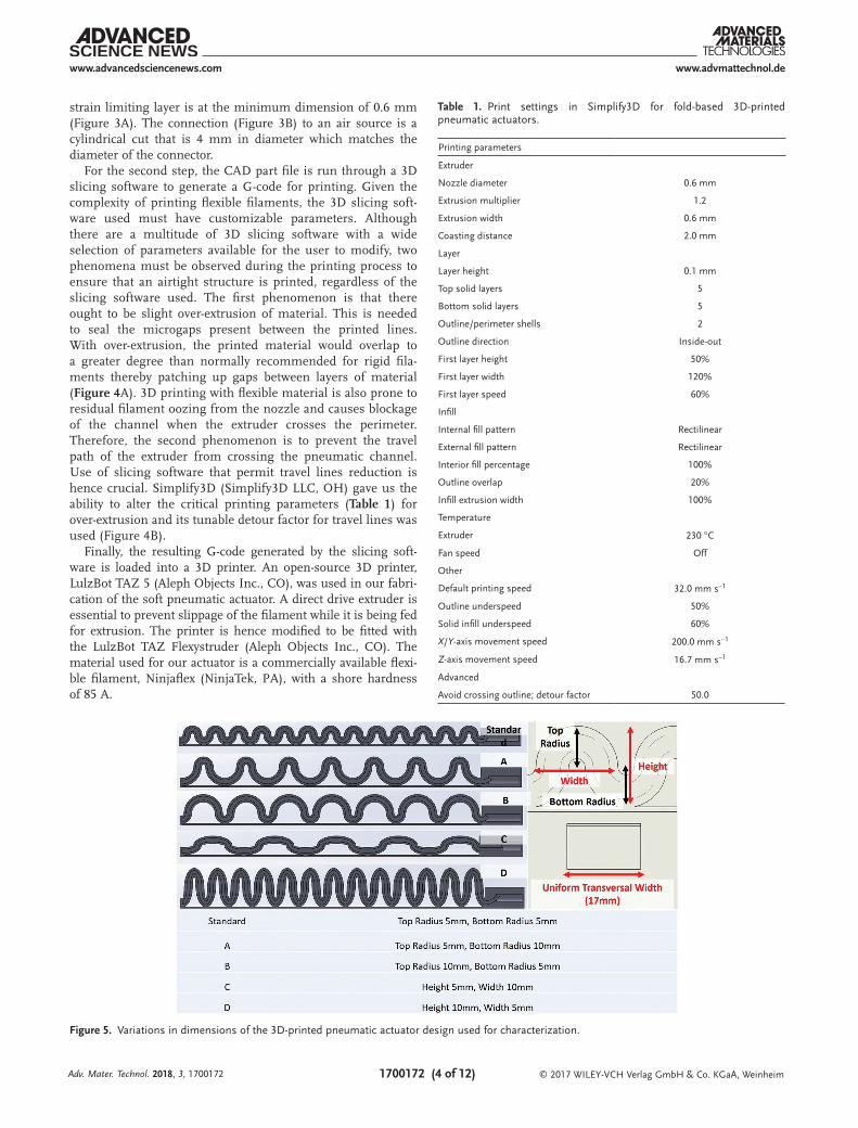
strain limiting layer is at the minimum dimension of 0.6 mm (Figure 3A). The connection (Figure 3B) to an air source is a cylindrical cut that is 4 mm in diameter which matches the diameter of the connector.
For the second step, the CAD part file is run through a 3D slicing software to generate a G-code for printing. Given the complexity of printing flexible filaments, the 3D slicing soft-ware used must have customizable parameters. Although there are a multitude of 3D slicing software with a wide selection of parameters available for the user to modify, two phenomena must be observed during the printing process to ensure that an airtight structure is printed, regardless of the slicing software used. The first phenomenon is that there ought to be slight over-extrusion of material. This is needed to seal the microgaps present between the printed lines. With over-extrusion, the printed material would overlap to a greater degree than normally recommended for rigid fila-ments thereby patching up gaps between layers of material (Figure 4A). 3D printing with flexible material is also prone to residual filament oozing from the nozzle and causes blockage of the channel when the extruder crosses the perimeter. Therefore, the second phenomenon is to prevent the travel path of the extruder from crossing the pneumatic channel. Use of slicing software that permit travel lines reduction is hence crucial. Simplify3D (Simplify3D LLC, OH) gave us the ability to alter the critical printing parameters (Table 1) for over-extrusion and its tunable detour factor for travel lines was used (Figure 4B).
Finally, the resulting G-code generated by the slicing soft-ware is loaded into a 3D printer. An open-source 3D printer, LulzBot TAZ 5 (Aleph Objects Inc., CO), was used in our fabri-cation of the soft pneumatic actuator. A direct drive extruder is essential to prevent slippage of the filament while it is being fed for extrusion. The printer is hence modified to be fitted with the LulzBot TAZ Flexystruder (Aleph Objects Inc., CO). The material used for our actuator is a commercially available flexi- ble filament, Ninjaflex (NinjaTek, PA), with a shore hardness of 85 A.
Adv. Mater. Technol. 2018, 3, 1700172
Table 1. Print settings in Simplify3D for fold-based 3D-printed pneumatic actuators.
Printing parameters
Extruder
Nozzle diameter 0.6 mm
Extrusion multiplier 1.2
Extrusion width 0.6 mm
Coasting distance 2.0 mm
Layer
Layer height 0.1 mm
Top solid layers 5
Bottom solid layers 5
Outline/perimeter shells 2
Outline direction Inside-out
First layer height 50%
First layer width 120%
First layer speed 60%
Infill
Internal fill pattern Rectilinear
External fill pattern Rectilinear
Interior fill percentage 100%
Outline overlap 20%
Infill extrusion width 100%
Temperature
Extruder 230 °C
Fan speed Off
Other
Default printing speed 32.0 mm s−1
Outline underspeed 50%
Solid infill underspeed 60%
X/Y-axis movement speed 200.0 mm s−1
Z-axis movement speed 16.7 mm s−1
Advanced
Avoid crossing outline; detour factor 50.0
Figure 5. Variations in dimensions of the 3D-printed pneumatic actuator design used for characterization.

www.advancedsciencenews.com
© 2017 WILEY-VCH Verlag GmbH & Co. KGaA, Weinheim1700172 (5 of 12)
www.advmattechnol.de
5. Characterization
In this section of study, dimensions of the folded channel are varied for characterization and illustrated in detail in Figure 5.
The overall length of the actuator was varied across the designs. While the length of the standard design was 157 mm, that of Designs A, B, C and of Design D, were chosen to be 155 and
Adv. Mater. Technol. 2018, 3, 1700172
Figure 6. a) Image analysis using ImageJ for calculation of curvature index using Equation (1) on the standard design pressurized at 200 kPa. Other bending states of the actuator at 200 kPa are also illustrated (Designs A to D). b) Detailed cross-section view of FEA model of each design emphasizing the difference in strain concentration along the valleys compared to the peaks in the fold design.
Table 2. Summarized experimental results of curvature index of the dif-ferent dimensions of actuators.
Curvature index (experimental)
Pressure [kPa]
Standard Design A Design B Design C Design D
0 1.000 1.000 1.000 1.000 1.000
50 1.060 1.179 1.095 1.063 1.349a)
100 1.107 1.320 1.218 1.057 1.559a)
150 1.210 1.400 1.267 1.066 1.830a)
200 1.292 1.400 1.337 1.071 1.970a)
a)The highest index at the given input pressure.
Table 3. Summarized results of curvature index of the different dimen-sions of actuators for FEA models with their percentage errors from the experimental results.
Curvature index (FEA models)
Pressure [kPa]
Standard Design A Design B Design C Design D
0 1.000 1.000 1.000 1.000 1.000
50 1.117 (±5%) 1.218 (±3%) 1.131 (±3%) 1.133 (±6%) 1.425 (±5%)
100 1.188 (±7%) 1.379 (±4%) 1.269 (±4%) 1.134 (±7%) 1.817 (±16%)
150 1.325 (±9%) 1.474 (±5%) 1.391 (±9%) 1.143 (±7%) 2.223 (±21%)
200 1.326 (±2%) 1.522 (±8%) 1.443 (±7%) 1.162 (±8%) 2.356 (±19%)

www.advancedsciencenews.com
© 2017 WILEY-VCH Verlag GmbH & Co. KGaA, Weinheim1700172 (6 of 12)
www.advmattechnol.de
159.6 mm, respectively. The top and bottom radii as well as the height and width of each fold were also varied across the designs. Three tests were done to characterize the performance of each actuator in terms of its curvature, torque output, and gripping force against the input pressure. A durability test was also done to investigate the number of cycles that the actuator could tolerate before fatigue and material failure.
5.1. Curvature Index
To compare between the relative bending capabilities between actuators of different dimensions, we defined a curvature index for each actuator using Equation (5). According to the equation, a higher index will indicate that a higher degree of bending
Curvature index,Outer length after actuation
Strain limiting layer1
2
IL
L=
(5)
The actuators are pressurized at incremental values of 50 kPa up to 200 kPa. Using an image analysis software (ImageJ, National Institute of Health, MD), measurements of L1 and L2 are obtained from captured images after pressurization (Figure 6A). Results are summarized in Table 2.
It is noted from Table 2 that Design D displayed the greatest degree of bending with the highest curvature index across the four pressures being used. From the FEA models (Figure 6B), the strain concentration in the valleys of the folds is observed
to be the largest in Design D. This validates our mathematical model in Equation (1) in that deeper valleys present in Designs D contribute to more work being done by the applied pressure due to an increase in unfolding distance d. Hence, a larger strain ΔL, would prompt a greater increase in outer length L2 over L1. Therefore, it can be concluded that the degree of bending is dependent on the depth of the valleys.
Our FEA models were further validated by comparing the curvature index obtained experimentally which yielded an error of under 10% (Table 3). Only Design D which exhibited large deformations had maximum errors of about 20%. The result was acceptable in predicting the general behaviors of the actua-tors across the designs.
5.2. Torque Output
To measure the maximum torque output that the actuators are capable of during bending, the following setup was adopted (Figure 7).
A torque sensor (FT01, Forsentek, China) was attached to two aluminum arms which were in turn connected via a hinge. The bending angle at which the torque measurement was recorded was fixed at 0° using a locking plate, with the proximal and distal ends of the actuator being constrained to the aluminum arms. Air pressure at incremental values of 50 kPa was then applied, up to a maximum of 200 kPa. Torque readings were recorded using an Arduino microprocessor and tabulated. The experiment was repeated three times and an
Adv. Mater. Technol. 2018, 3, 1700172
Figure 7. Experimental setup (left) for measuring torque output. A schematic diagram (right) shows the actuator being secured at 0° and upon air pressurization, the actuator exerts a torque measured by the torque sensor.
Table 4. Averaged torque measurement at a bending angle of 0° at 50, 100, 150, and 200 kPa.
Pressure [kPa] Standard Design A Design B Design C Design D
50 0.057 ± 0.02 0.088 ± 0.02 0.071 ± 0.01 0.140 ± 0.05a) 0.053 ± 0.01
100 0.126 ± 0.02 0.187 ± 0.03 0.136 ± 0.03 0.326 ± 0.06a) 0.137 ± 0.01
150 0.217 ± 0.02 0.289 ± 0.06 0.223 ± 0.04 0.461 ± 0.03a) 0.277 ± 0.02
200 0.325 ± 0.02 0.456 ± 0.01 0.300 ± 0.03 0.543 ± 0.04a) 0.436 ± 0.02
a)The highest reading at the given pressure.

www.advancedsciencenews.com
© 2017 WILEY-VCH Verlag GmbH & Co. KGaA, Weinheim1700172 (7 of 12)
www.advmattechnol.de
Adv. Mater. Technol. 2018, 3, 1700172
Figure 8. a) Experimental setup for measuring force needed to uncurl the actuator, that is, grip strength. b) Grip force against displacement graph obtained from Instron measurements.

www.advancedsciencenews.com
© 2017 WILEY-VCH Verlag GmbH & Co. KGaA, Weinheim1700172 (8 of 12)
www.advmattechnol.de
averaged value was obtained across the three trials and sum-marized in Table 4.
5.3. Grip Strength
For our grip strength tests, we used the Instron Universal Tester 3345 (Instron, MA). The actuator was first anchored to the base plate of the Instron machine as seen in Figure 8A.
Upon pressurization at 200 kPa, the actuator was made to grip a cylinder of diameter 50 mm. Subsequently, the cylinder was pulled upward at a velocity of 8 mm s−1 and the grip force of the actuator is measured throughout pulling until it loses grip on the cylinder. The graph of the grip strength recorded across the five actuators is shown in Figure 8B. The highest and lowest grip strength attainable at 200 kPa were 25.21 N (Design D) and 2.05 N (Design C).
5.4. Durability Test
It is important to estimate the approximate lifespan of the 3D-printed actuator to evaluate its performance. Each design of the actuator is set to be pressurized at 200 kPa at a frequency of 0.5 Hz. The total number of cycles are recorded before the actuator showed signs of material fatigue and failure between printed layers of the actuator, evident by the leakage of pressur-ized air and its inability to reach the set pressure of 200 kPa. The tip force exerted by the bending actuator during each pres-surization cycle was also measured to investigate the efficiency of the actuator as material fatigue sets in. The setup used for
this test is shown in Figure 9. Table 5 and Figure 10 show the results of the durability test.
From Table 5, it can be concluded that Design D is the most durable. As seen in Figure 10 there is also no noticeable trend in the average tip force attainable by the actuators as the pres-surization cycles progressed. The 3D-printed actuators proved to provide a stable force output throughout the activation cycles, with a low coefficient of variation (<0.16) across the five designs.
However, it was observed that the actuators needed some time to achieve stable actuation. A relatively larger standard deviation in the average tip force is measured during the first ten cycles and decreases during the median ten cycles, across the different designs. As the actuator reaches failure, the slight increase in standard deviation in the last ten cycles is credited to the increasing instability as material fatigue sets in.
6. Customizability of Fold-Based Design
It is evident from the studies done that the dimensions of the folds and the placement of the strain limiting layer along the
Adv. Mater. Technol. 2018, 3, 1700172
Figure 9. Experimental setup for calculating maximum number of cycles tolerable is shown. The actuator is placed on a force sensor to measure the unrestrained tip force output as the cycles proceeded.
Table 5. Number of cycles attained before material fatigue and failure for different designs of the 3D-printed pneumatic actuator.
Type of actuator Average number of cycles (n = 3)
Standard 5119 ± 1354
Design A 1403 ± 338
Design B 2357 ± 229
Design C 1142 ± 428
Design D 6473 ± 128
Figure 10. Measurement of average bending force output by the different designs of the 3D-printed pneumatic actuator over the duration of cyclic testing (n = 3). Coefficient of variation for the five designs in the first, median, and last, respectively, are as follows: Standard: (0.12, 0.14, 0.09), Design A: (0.09, 0.06, 0.09), Design B: (0.04, 0.04, 0.05), Design C: (0.11, 0.04, 0.06), Design D: (0.16, 0.13, 0.09).

www.advancedsciencenews.com
© 2017 WILEY-VCH Verlag GmbH & Co. KGaA, Weinheim1700172 (9 of 12)
www.advmattechnol.de
actuator affect the degree of bending in the actuator. With the ability of CAD modeling to create complicated designs, dif-ferent bending profiles of 3D-printed actuators can be realized as illustrated in Figure 11.
By varying the types of folds along the actuator, different degrees of bending can be programmed accordingly. In addi-tion, by changing the attachment point of the strain limi-ting layer to the folds of the actuator, the type of bending and the location of bending along the actuator can be pro-grammed. For instance, if the strain limiting layer is printed in a spiral fashion, the result is a twisting actuator whose pitch is determined by the pitch of the spiraling strain limi-ting layer printed on the body of the actuator. Also, removal of the strain limiting layer would result in lengthening of the segment.
The ability to achieve different bending profiles demon-strates the versatility of the fold-based approach toward creating an actuator that can be used for a variety of applications.
7. Applications
The utility of the 3D-printed fold-based actuator with different designs is demonstrated in three different applications, mainly for object manipulation, locomotion in soft robots, and as wear-able devices.
7.1. Robotic Gripper
The linear bending profile of the 3D-printed actuator can pri-marily be used for object manipulation in the form of a soft robotic gripper. In our demonstration (Figure 12), we show that at a pressure of about 175 kPa, a soft robotic gripper equipped with four linear bending actuators, each with five folds, can hold an object weighing 0.94 kg (Figure 12b).
Adv. Mater. Technol. 2018, 3, 1700172
Figure 11. Different bending profiles can be achieved through variations of fold designs and placement of the strain limiting layer. The actuator is shown in both its a) original state and b) after it is pressurized at 200 kPa.
Figure 12. Demonstration of a) robotic gripper equipped with 3D-printed pneumatic actuators picking up b) a 0.94 kg structure and c–j) items of different shapes, sizes, and weight using 175 kPa of pressure. j) A second robotic gripper with outward facing 3D-printed pneumatic actuators that can grasp k) inside of a cylindrical can and l) roll of tape.
www.advancedsciencenews.com
© 2017 WILEY-VCH Verlag GmbH & Co. KGaA, Weinheim1700172 (10 of 12)
www.advmattechnol.de
Although the 3D-printed actuators can generate high bending force upon pressuri-zation, the soft characteristics of the actuator allow the robotic gripper to manipulate deli-cate objects. Upon encountering a resistive force, the soft actuator buckles naturally pre-venting exertion of excessive tip force and instead conforms to the surface of the object, minimizing damage done to it. The same soft robotic gripper that can hold 0.94 kg of weight at 175 kPa does not cause bruising to daily food products (Figure 12e–h). This is particularly useful for industrial applications like handling and packaging of food items that require delicate manipulation.
7.2. Locomotion in Worm Robots
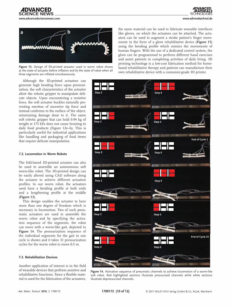
The fold-based 3D-printed actuator can also be used to assemble an autonomous soft worm-like robot. The 3D-printed design can be easily altered using CAD software along the actuator to achieve different actuation profiles. In our worm robot, the actuators used have a bending profile at both ends and a lengthening profile at the middle (Figure 13).
This design enables the actuator to have more than one degree of freedom which is necessary in locomotion. Two of such pneu-matic actuators are used to assemble the worm robot and by specifying the activa-tion sequence of the segments, the robot can move with a worm-like gait, depicted in Figure 14. The pressurization sequence of the individual segments for the gait in one cycle is shown and it takes 31 pressurization cycles for the worm robot to move 0.5 m.
7.3. Rehabilitation Devices
Another application of interest is in the field of wearable devices that perform assistive and rehabilitative functions. Since a flexible mate-rial is used for the fabrication of the actuators,
the same material can be used to fabricate wearable interfaces like gloves, on which the actuators can be attached. The actu-ators can be used to augment a stroke patient’s finger move-ments in the form of a glove rehabilitative device (Figure 15) using the bending profile which mimics the movements of human fingers. With the use of a dedicated control system, the glove can be programmed to perform different hand exercises and assist patients in completing activities of daily living. 3D printing technology is a low-cost fabrication method for home-based rehabilitative therapy and patients can manufacture their own rehabilitative device with a consumer-grade 3D printer.
Adv. Mater. Technol. 2018, 3, 1700172
Figure 13. Design of 3D-printed actuator used in worm robot shows a) the state of actuator before inflation and b) the state of robot when all three segments are inflated simultaneously.
Figure 14. Activation sequence of pneumatic channels to achieve locomotion of a worm-like soft robot. Red highlighted sections illustrate pressurized channels while white sections illustrate depressurized channels.

www.advancedsciencenews.com
© 2017 WILEY-VCH Verlag GmbH & Co. KGaA, Weinheim1700172 (11 of 12)
www.advmattechnol.de
8. Conclusions and Future Work
In this work, we present a new method of designing and fab-ricating soft robotic actuators. The fold-based design approach has shown its efficiency and versatility when applied to pneu-matic actuators, evident by its ability to be used in a variety of applications with adequate force and torque output. 3D printing as a fabrication method has ensured that the actuators are of a consistent quality and performance.
Sensing with 3D-printed sensors can also be incorporated into the actuator in a single 3D printing fabrication step. This will enable precise control and study of the actuator’s bending behavior in future. The obstacle then lies in identifying different and com-patible conductive materials that can be printed onto each other but still provide strong adhesion. Current techniques used to 3D print sensors and the materials used might not be compatible with the Ninjaflex flexible filament used to print the 3D-printed actuator and there is a need to develop a new type of flexible and conductive composite material to pair with the actuator.
AcknowledgementsThis work was supported by the MOE AcRF Tier 2 research grant (R-397-000-203-112). Informed signed consent of all participants in this study was obtained prior to the conduct of the experiments in fulfillment of ethical obligations. Author initials were updated on February 12, 2018, following initial publication in early view.
Conflict of InterestThe authors declare no conflict of interest.
Keywords3D printing, pneumatic actuators, printable actuators, printable devices, soft robotics
Received: June 30, 2017Revised: September 11, 2017
Published online: December 4, 2017
[1] Y. Hao, Z. Gong, Z. Xie, S. Guan, X. Yang, Z. Ren, T. Wang, L. Wen, in 2016 35th Chinese Control Conf. (CCC), IEEE, Piscataway, New Jersey, USA 2016, pp. 6109–6114.
[2] B. S. Homberg, R. K. Katzschmann, M. R. Dogar, D. Rus, in 2015 IEEE/RSJ Int. Conf. Intelligent Robots and Systems (IROS), IEEE, Piscataway, New Jersey, USA 2015, pp. 1698–1705.
[3] G. Rateni, M. Cianchetti, G. Ciuti, A. Menciassi, C. Laschi, Meccanica 2015, 50, 2855.
[4] J. H. Low, C. H. Yeow, J. Vis. Exp. 2016, 114, e54175.[5] F.Z. Low, H. H. Tan, J. H. Lim, C.H. Yeow, J. Med. Devices 2016, 10,
014503-1–014503-5.[6] M. Haghshenas-Jaryani, W. Carrigan, M. B. J. Wijesundara,
R. M. Patterson, N. Bugnariu, T. Niacaris, presented at ASME 2016 Int. Design Engineering Technical Conf. Computers and Information in Engineering Conf., Charlotte, NC, August 2016.
[7] H. Al-Fahaam, S. Davis, S. Nefti-Meziani, presented at 2016 21st Int. Conf. Methods and Models in Automation and Robotics (MMAR), Miedzyzdroje, Poland, August 2016.
[8] N. Elango, A. A. M. Faudzi, Int. J. Adv. Manuf. Technol. 2015, 80, 1027.
[9] N. Cheney, J. Bongard, H. Lipson, presented at Proc. 2015 Annual Conf. Genetic and Evolutionary Computation, Madrid, Spain, July 2015.
[10] A. Albu-Schaffer, O. Eiberger, M. Grebenstein, S. Haddadin, C. Ott, T. Wimbock, S. Wolf, IEEE Rob. Autom. Mag. 2008, 15, 20.
Adv. Mater. Technol. 2018, 3, 1700172
Figure 15. A 3D-printed rehabilitation glove equipped with the printed pneumatic actuators. a) Assembled CAD model of the 3D-printed glove. b) Individual components of a functional rehabilitative and assistive device that uses electromyography muscle signals for control. c) The 3D-printed glove being used to grasp an object.

www.advancedsciencenews.com
© 2017 WILEY-VCH Verlag GmbH & Co. KGaA, Weinheim1700172 (12 of 12)
www.advmattechnol.de
[11] N. W. Bartlett, V. Lyau, W. A. Raiford, D. Holland, J. B. Gafford, T. D. Ellis, C. J. Walsh, J. Med. Devices 2015, 9, 030918.
[12] K. W. Wait, P. J. Jackson, L. S. Smoot, presented at IEEE Int. Conf. Robotics and Automation, Anchorage, Alaska, May 2010.
[13] C. D. Onal, X. Chen, G. M. Whitesides, D. Rus, in Robotics Research: The 15th Int. Symp. ISRR, Springer, Berlin, Germany 2017, p. 525.
[14] R. F. Shepherd, F. Ilievski, W. Choi, S. A. Morin, A. A. Stokes, A. D. Mazzeo, X. Chen, M. Wang, G. M. Whitesides, Proc. Natl. Acad. Sci. USA 2011, 108, 20400.
[15] J. Hughes, U. Culha, F. Giardina, F. Guenther, A. Rosendo, F. Iida, Front. Rob. AI 2016, 3, 1.
[16] P. Polygerinos, Z. Wang, K. C. Galloway, R. J. Wood, C. J. Walsh, Robotics Auton. Syst. 2015, 73, 135.
[17] P. Yong-Lae, C. Bor-rong, O. P.-A. Néstor, Y. Diana, S. Leia, J. W. Robert, C. G. Eugene, N. Radhika, Bioinspiration Biomimetics 2014, 9, 016007.
[18] H. K. Yap, N. Kamaldin, J. H. Lim, F. A. Nasrallah, J. C. H. Goh, C. H. Yeow, IEEE Trans. Neural Syst. Rehabil. Eng. 2017, 25, 782.
[19] I. N. A. M. Nordin, A. M. Faudzi, S. Wakimoto, K. Suzumori, presented at 10th Asian Control Conf. (ASCC), Kota Kinabalu, Malaysia, May 2015.
[20] F. Ilievski, A. D. Mazzeo, R. F. Shepherd, X. Chen, G. M. Whitesides, Angew. Chem., Int. Ed. Engl. 2011, 50, 1890.
[21] H. K. Yap, B. W. K. Ang, J. H. Lim, J. C. H. Goh, C. H. Yeow, presented at IEEE Int. Conf. Robotics and Automation (ICRA), Stockholm, Sweden, May 2016.
[22] H. K. Yap, H. Y. Ng, C.-H. Yeow, Soft Rob. 2016, 3, 144.
Adv. Mater. Technol. 2018, 3, 1700172

本文献由“学霸图书馆-文献云下载”收集自网络,仅供学习交流使用。
学霸图书馆(www.xuebalib.com)是一个“整合众多图书馆数据库资源,
提供一站式文献检索和下载服务”的24 小时在线不限IP
图书馆。
图书馆致力于便利、促进学习与科研,提供最强文献下载服务。
图书馆导航:
图书馆首页 文献云下载 图书馆入口 外文数据库大全 疑难文献辅助工具