A novel current controller design for grid-integrated PV ...
16
Vol.:(0123456789) SN Applied Sciences (2021) 3:323 | https://doi.org/10.1007/s42452-021-04290-4 Research Article A novel current controller design for grid‑integrated PV inverter system Ayaz Ahmad 1 · L. Rajaji 2 · A. Iqbal 3 Received: 14 September 2020 / Accepted: 28 January 2021 / Published online: 15 February 2021 © The Author(s) 2021 OPEN Abstract Distributed generators are playing a vital role in supporting the grid in ever-increasing energy demands. Grid code regulation must be followed when integrating the photovoltaic inverter system to the grid. The paper investigates and analyzes a controller model for grid-connected PV inverters to inject sinusoidal current to the grid with minimum dis- tortion. To achieve better tracking and disturbance rejection, a DSP-based current controller is designed with LCL filter. The controller gets the current feedback from the grid, compares it with reference current, and calculates duty cycle to generate PWM pulses to trigger H-bridge converters. The grid voltage is loaded to the initial value in proposed PR controller to ensure the initial inverter voltage to match the grid voltage. The paper presents a novel current controller algorithm for grid-connected inverter system, and simulation is done. A detailed analysis has been carried out to validate the proposed design algorithm. Experimental implementation of the current controller in the DC/AC converter circuits with an LCL filter is done for 5.4 kW to validate and match the simulation model. Keywords CCA · DC/AC · DC/DC · PWM · PR 1 Introduction Better technology, reduced cost, and efficient system are encouraging greening the grid. In the present time, distributed generators are inevitably integrated with the utility grid to meet the increasing power demands. The integration of such a generator must follow the grid code requirement to give and take power from the grid. Solar inverter system comprises an array of solar panels, DC/DC converter, and DC/AC converter, and both are cou- pled with the help of DC link capacitor as shown in Fig. 1. This solar inverter is connected to the power utility grid system through LCL filters. Output ac power is fil- tered by the LCL filter to mitigate the harmonics and feed to the grid. Current control strategies play a vital role in the performance of distributed solar power system. An overview of power converters and their various topolo- gies is depicted in [1]. A comparative study is being carried out for PI and PR controller by [2, 3]. Inverters in distributed power generation (DG) systems include dc–ac conver- sion, output power quality assurance, various protection mechanisms, and system controls [4]. To compensate the grid harmonics and provide disturbance rejection capa- bility, stationary-frame generalized integrators are used to control the fundamental current [5]. A low-cost grid- connected residential scheme is suggested in [6] based on dynamic voltage or current error signals activating a PI controller. Another controller used is low-pass filter in the feedback path along with harmonic compensator to improve the grid current quality [7]. Proportional resonant (PR) controller is an algorithm used in the current control- ler which is used to integrate the PV inverter into the grid. * Ayaz Ahmad, [email protected] | 1 Department of Engineering, University of Technology and Applied Science, Ibra, Oman. 2 Department of Electrical Engineering, ARM College of Engineering and Technology, Chennai, India. 3 Department of Electrical Engineering, Qatar University, Doha, Qatar.
Transcript of A novel current controller design for grid-integrated PV ...

Vol.:(0123456789)
SN Applied Sciences (2021) 3:323 | https://doi.org/10.1007/s42452-021-04290-4
Research Article
A novel current controller design for grid‑integrated PV inverter system
Ayaz Ahmad1 · L. Rajaji2 · A. Iqbal3
Received: 14 September 2020 / Accepted: 28 January 2021 / Published online: 15 February 2021 © The Author(s) 2021 OPEN
AbstractDistributed generators are playing a vital role in supporting the grid in ever-increasing energy demands. Grid code regulation must be followed when integrating the photovoltaic inverter system to the grid. The paper investigates and analyzes a controller model for grid-connected PV inverters to inject sinusoidal current to the grid with minimum dis-tortion. To achieve better tracking and disturbance rejection, a DSP-based current controller is designed with LCL filter. The controller gets the current feedback from the grid, compares it with reference current, and calculates duty cycle to generate PWM pulses to trigger H-bridge converters. The grid voltage is loaded to the initial value in proposed PR controller to ensure the initial inverter voltage to match the grid voltage. The paper presents a novel current controller algorithm for grid-connected inverter system, and simulation is done. A detailed analysis has been carried out to validate the proposed design algorithm. Experimental implementation of the current controller in the DC/AC converter circuits with an LCL filter is done for 5.4 kW to validate and match the simulation model.
Keywords CCA · DC/AC · DC/DC · PWM · PR
1 Introduction
Better technology, reduced cost, and efficient system are encouraging greening the grid. In the present time, distributed generators are inevitably integrated with the utility grid to meet the increasing power demands. The integration of such a generator must follow the grid code requirement to give and take power from the grid.
Solar inverter system comprises an array of solar panels, DC/DC converter, and DC/AC converter, and both are cou-pled with the help of DC link capacitor as shown in Fig. 1.
This solar inverter is connected to the power utility grid system through LCL filters. Output ac power is fil-tered by the LCL filter to mitigate the harmonics and feed to the grid. Current control strategies play a vital role in the performance of distributed solar power system. An
overview of power converters and their various topolo-gies is depicted in [1]. A comparative study is being carried out for PI and PR controller by [2, 3]. Inverters in distributed power generation (DG) systems include dc–ac conver-sion, output power quality assurance, various protection mechanisms, and system controls [4]. To compensate the grid harmonics and provide disturbance rejection capa-bility, stationary-frame generalized integrators are used to control the fundamental current [5]. A low-cost grid-connected residential scheme is suggested in [6] based on dynamic voltage or current error signals activating a PI controller. Another controller used is low-pass filter in the feedback path along with harmonic compensator to improve the grid current quality [7]. Proportional resonant (PR) controller is an algorithm used in the current control-ler which is used to integrate the PV inverter into the grid.
* Ayaz Ahmad, [email protected] | 1Department of Engineering, University of Technology and Applied Science, Ibra, Oman. 2Department of Electrical Engineering, ARM College of Engineering and Technology, Chennai, India. 3Department of Electrical Engineering, Qatar University, Doha, Qatar.

Vol:.(1234567890)
Research Article SN Applied Sciences (2021) 3:323 | https://doi.org/10.1007/s42452-021-04290-4
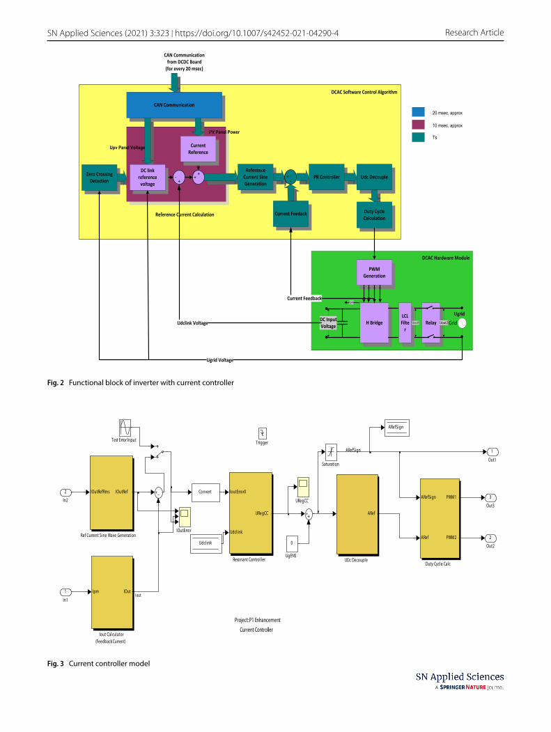
A repetitive control strategy is implemented to claim a superior tracking and harmonic rejection capability by applying mu synthesis principle [8]. Detailed investiga-tion on power control and current control strategies has been elaborated in [9–12]. Various control algorithms are presented for active and reactive power control when PV inverters are connected to the grid as given by [13–16]. An improved DSP-based controller with predictive and fuzzy logic-based current controller is investigated in [17]. The contribution of power electronics on the effi-ciency improvement and current harmonics reduction in the grid-connected photovoltaic system is described in [18–21]. The transformerless PV inverter is explained, to minimize the DC component on the injected AC current [22]. Various control strategies, optimization techniques, and analysis have been investigated to implement cur-rent control algorithms [23–28]. A comprehensive design methodology of PR controller with zero steady-state error for single-phase grid-connected system is presented by [29]. This paper proposes a novel design and modeling of the current controller for single-phase grid-connected inverter system. The main functional blocks are shown in Fig. 2.
2 Proposed current controller for DC/AC module
The current controller algorithm (CCA) is part of the DC/AC Module. The current controller reads the grid voltage, phase, frequency, and generates the electrical power based on the solar panel input power and DC link voltage. Inverter power is fed to the grid in phase with the grid volt-age. The proposed current controller comprises zero cross-ing detector for phase and frequency of the grid voltage. Reference current calculation is done to deliver maximum
available power to the grid. The instantaneous reference current is generated using the reference current sine wave generator. The current delivered to the grid is measured through feedback. PR controller is used to compute PWM duty cycle from the error current.
3 Modeling and simulation of current controller
The current controller is the critical functionality of the DC/AC module and is executed for every sample time Ts. The Simulink model of the current controller is shown in Fig. 3. In this model, the current reference calculation is done for every half cycle that is used for generation of instantane-ous reference current sine wave. So, generated instanta-neous current sine wave is compared with the feedback current, and error is fed to the PR controller. The output of the PR controller is decoupled with UDC by dividing the URegCC value with UDC link voltage. The current control-ler outputs the PWM duty cycle value in the range of 0–65, 535 in each direction of the sine wave.
The current reference offset in current reference genera-tion is not used in the model and grid resistance compen-sation is not included in the model.
Zero crossing detector (ZCD) detects the zero crossings of grid voltage measured at Point of Common Coupling (PCC). ZCD executes every sample time, Ts. Input samples are downsized by 5*Ts and select the median value out of 3 successive inputs. The predictive FIR filter is a digital filter to predict the next sample from the previous consecutive 11 inputs. The output of the predictive FIR filter is interpo-lated to get 4 intermediate samples. The interpolated sam-ples are verified for the zero crossing and the correspond-ing cycle time is used for computing the grid frequency. The output of the ZCD is shown in Fig. 4. The number of
Fig. 1 A grid-tied solar inverter system
Vol.:(0123456789)
SN Applied Sciences (2021) 3:323 | https://doi.org/10.1007/s42452-021-04290-4 Research Article
Zero CrossingDetection
CAN Communication
GridRelayH BridgeLCLFilte
r
DC InputVoltage
Uout1
Ipm
Uout2
Ugrid
DCAC Hardware Module
DCAC Software Control Algorithm
PWMGeneration
Ugrid Voltage
CAN Communicationfrom DCDC Board
(for every 20 msec)
10 msec, approx
20 msec, approx
Ts
Reference Current Calculation
-+
++
ReferenceCurrent SineGeneration
+-
PR Controller Udc Decouple
Duty CycleCalculation
Current Feedack
Udclink Voltage
Current Feedback
DC linkreference
voltage
CurrentReference
PV Panel Power
Upv Panel Voltage
Fig. 2 Functional block of inverter with current controller
ARefSign
Project: P1 Enhancement
Current Controller
3
Out3
2
Out2
1
Out1
0
UgENS
URegCC
ARef
UDc Decouple
Test Error Input
Saturation
IoutError0
Udclink
URegCC
Resonant Controller
IOutRefRms IOutRef
Ref Current Sine Wave Generation
Ipm IOut
Iout Calculator(Feedback Current)
IOutError
ARefSign
ARef
PWM1
PWM2
Duty Cycl e Calc
Convert
ARefSign
Udclink
Trigger
2
In2
1
In1Iout
Fig. 3 Current controller model

Vol:.(1234567890)
Research Article SN Applied Sciences (2021) 3:323 | https://doi.org/10.1007/s42452-021-04290-4
samples for every cycle is fixed as 170. The minor variation in grid frequency is handled by changing the sampling time. For every grid voltage cycle, the new sampling time is manipulated.
The RMS value of the reference current is calculated for every half cycle of grid voltage. Panel power (Ppv) from DC/DC board through CAN communication, DC link volt-age (Udclink), grid voltage (Ugrid) are used for comput-ing current reference (IoutRefRMS) in current controller algorithm.
Feedback current for the current controller is measured from the negative H-bridge of the DC/AC switching cir-cuit. Current in the negative H-bridge is discontinuous DC because of PWM switching. There is no filter involved in the feedback measuring circuit and it is mandatory to sample the current in the middle of the PWM duty cycle to ensure the average current measurement for each PWM pulse. This synchronization of current ADC and H-bridge PWM is available in the DSP processor and explicitly brought out in the Matlab model. The sampled current is converted to sinusoidal wave by considering the polarity of the grid voltage and thus represents the current feedback to the current controller of the inverter. This current feedback is compared with the current reference to compute the
SamplingTime, Ts = GridFrequency∕170.
current error. This current error from reference is given as input to the PR controller.
PR controller is the inner loop controller, the output is based on the error current value, that means it estimates the output voltage along with the harmonic compensa-tors. It has 1st, 3rd, 5th, and 7th harmonic compensators with a frequency of 50 Hz, 150 Hz, 250 Hz, and 350 Hz, respectively. Based on the current error value, the high-est frequency of the resonant controller will be chosen. Modeling of proportional resonant (PR) controller is shown in Fig. 5.
PR controller block has the advantage of visualizing the outputs of each harmonic compensator. Harmonic components HC5 and Harmonics components HC7 are subjected to anti-windup to limit the peak output. PR controller is discretized using the Backward and Back-ward Euler method and used in the discretized method as can be seen from Eq. 1.
In Fig. 6, the outputs of each harmonic compensator are probed. From Fig. 6, it is observed that the amplitude of fundamental frequency is much higher than the 3rd, 5th, and 7th order frequencies.
(1)
Harmonic Compensator Rb & b(Z) =Ts
(
1 − Z−1)
1 +(
20T 2s− 2
)
Z−1 + Z−2.
Fig. 4 Output of ZCD

Vol.:(0123456789)
SN Applied Sciences (2021) 3:323 | https://doi.org/10.1007/s42452-021-04290-4 Research Article
DC link voltage is decoupled from PR controller out-put by dividing the PR controller output by DC link voltage.
Figure 7 shows the cumulative output of the propor-tional controller and Harmonic compensators (HC1, HC3, HC5, and HC7).
DSP calculates the duty cycle from the CCA and gener-ates PWM pulses to trigger the H-bridge gate as shown
Fig. 5 PR controller
Fig. 6 Output of PR controller
Fig. 7 Consolidated output of PR controller

Vol:.(1234567890)
Research Article SN Applied Sciences (2021) 3:323 | https://doi.org/10.1007/s42452-021-04290-4
in Fig. 8. DC link voltage source forms DC input to the H-bridge.
PWM carrier frequency is twice as that of the sampling frequency. For every sampling time (8.5 kHz approx.), the current control algorithm computes the duty cycle based on the error current and generates PWM pulses of 17 kHz. Zero crossing detection calculates frequency for every period (grid voltage) and this decides the PWM frequency for the next cycle.
Feedback current sensor is mounted on the negative H-bridge. Feedback current is discontinuous and there is no filter available in the current sensor measuring circuit. DSP is expected to read feedback current when the PWM gate is switched ON and also at the mid of the PWM pulse to ensure the read value is average feedback current. Feed-back current is measured in mid of the second PWM pulse. Time delay of 0.75*Ts is involved in reading the feedback current from the PWM output.
Feedback current is calculated by ADC quantizer as shown in Fig. 9. Feedback current module samples the cur-rent in the mid of the PWM pulse on negative H-bridge. The sampled current is quantized as 10-bit values in the scale of -52.03A to + 52.03 A (for 5.4 kW). Figure 10 shows the current input and current output of the feedback cur-rent module. Since the current is measured in the negative H-bridge, the current is unidirectional, and sign conversion is required for the negative cycle of the sine wave.
Figure 11 illustrates the reference current, feedback cur-rent, and the error current. Table 1 shows the time-domain
Fig. 8 H-bridge circuit in PLECS
Fig. 9 ADC quantizer for feed-back current

Vol.:(0123456789)
SN Applied Sciences (2021) 3:323 | https://doi.org/10.1007/s42452-021-04290-4 Research Article
characteristics of the error current. The error current is high for the first cycle and in steady state, the average error reads out 9 × 52.03 / 1024 = 457 mA (Scaling + 52.03A—1024). Figure 12 shows the feedback current measured at the negative H-bridge, the input side of the inverter circuit. From this current, the average current is estimated, and feedback current is calculated.
The average current along with feedback current is shown in Fig. 13.
Figure 14 explains how the average current sampled at mid of PWM pulse width and then it is fed back as current feedback signal to the current controller.
LCL filter is connected across the inverter output to filter out the current harmonics while power flows from inverter to power grid. Figure 15 shows the power circuit of the LCL filter. The current control loop of the LCL filter is shown in Fig. 16.
LCL filter circuit parameters are detailed in Table 2
4 Simulation results
When relay connects the inverter to the grid, the initial inverter voltage is set based on the previous half cycle of grid voltage as shown in Fig. 17. The grid voltage is loaded to the initial value in PR controller to ensure the initial
inverter voltage to match the grid voltage. In simulation, reference current is made to 5.4 kW, and the maximum overshoot is absorbed to be 46%. In practice, initial power delivered is limited and increases in step to reach the maxi-mum rated power.
The inverter output voltage, output current, and out-put power at steady-state condition are shown in Fig. 18. In Fig. 18, RMS values of voltage, current, and power are taken to explain the stability of the inverter. From this fig-ure, it has been observed that the RMS value of the volt-age at steady-state condition is 230 V and the RMS value
Current in Amps
Current in ADC Count
Fig. 10 Input and output of current feedback
Fig. 11 Reference current, feedback current, and error current
Table 1 Error current—characteristics
Current refer-ence–feedback current
Maximum error value (instantaneous) −240Avg. steady-state error (for one cycle) 9

Vol:.(1234567890)
Research Article SN Applied Sciences (2021) 3:323 | https://doi.org/10.1007/s42452-021-04290-4
of current at steady-state condition is 23.5 A and the RMS power is 5.4 kW. Multiplication of voltage and current val-ues is observed from the graph shown in Fig. 18. The other simulation results are described in Table 3.
[
5 Experimental implementation and results
Experimental implementation of the current controller in the DC/AC converter circuits with LCL filter for a single-phase bidirectional inverter system is done and results
are obtained. The proposed algorithm is implemented using 32-bit fixed-type TMS320F2812 DSP processor. The current controller reads the grid voltage, phase, fre-quency, and generates the electrical power based on the solar panel input power and DC link voltage. Inverter power is fed to the grid in phase with the grid voltage. H-bridge along with the filter converts the DC into AC specified by the grid parameters. STPOWER V channel 600 V IGBT suitable for solar inverter application is used as bridge. IGBT gates are driven by the PWM signals gen-erated by DSP and isolated using gate drive optocou-pler HCPL3120 which can source a minimum of 2A peak output current. Signal conditioning circuits are used to feed the DC voltage, inverter voltage/frequency, and the grid voltage/frequency to the DSP for feedback and control purposes. Also, the current through the power module and temperature of the power module have been measured by the DSP. ENS functionality is added using microcontroller. ENS monitors the grid voltage and frequency and controls the output relay which con-nects the inverter to the grid. ENS communicates with DSP through dedicated serial interface.
The current following through the H-bridge has been measured through a sense resistor of value 7.5mΩ. The voltage across 7.5mΩ has been amplified with a gain of ~ 8.15, which is then compared against the limit to dis-able the PWM signals during over current or reverse cur-rent flow.
PWM_HALT, a halt signal, is activated when the current through the power modules exceeds 60A or when there is reverse current flow beyond 44A in the power modules. The output of the sensor is shown in Fig. 19.
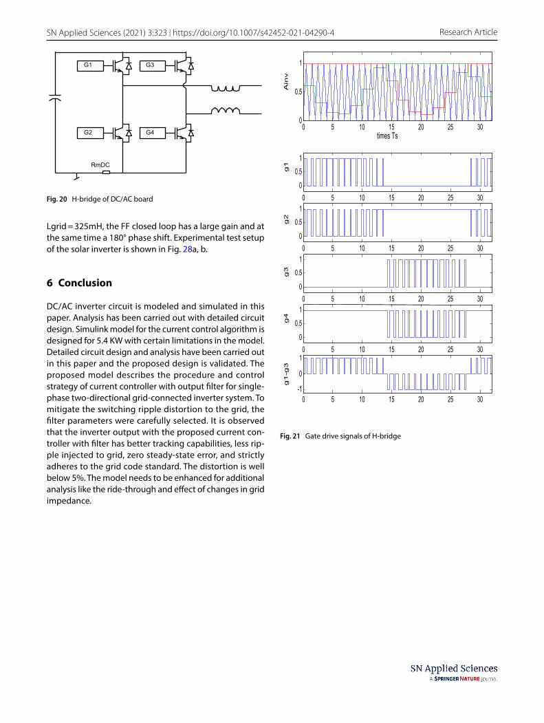
The DC/AC inverter is based on an H-bridge converter as shown in Fig. 20. The output is connected to the utility in a single-phase configuration through an LCL filter.
Fig. 12 Feedback current waveform observed from negative H-bridge
Fig. 13 Feedback and average current waveforms observed from negative H-bridge
Fig. 14 Zoomed current waveform from negative H-bridge

Vol.:(0123456789)
SN Applied Sciences (2021) 3:323 | https://doi.org/10.1007/s42452-021-04290-4 Research Article
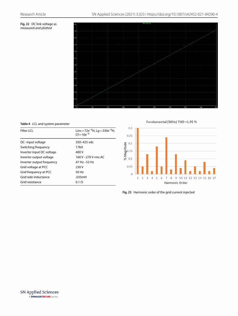
The switching frequency has been measured as 17 kHz. Gate drive signals of H-bridge circuit are shown in Fig. 21. Figure 22 shows the DC link voltage concerning the posi-tive polarity of the input voltage. Voltage is measured
Fig. 15 LCL filter circuit
Fig. 16 Current control loop of LCL filter circuit
Table 2 LCL filter circuit parameters
Parameters Values Remarks
Lc 330e−6 Nominal valueRc 0.02Lm 72e−6 Nominal valueRfe inf, 200Rm 0.008Cf 10e-6Cd 2.2e-6Rd 20ohm
Fig. 17 Grid voltage and inverter output current

Vol:.(1234567890)
Research Article SN Applied Sciences (2021) 3:323 | https://doi.org/10.1007/s42452-021-04290-4
from the experimental setup and then it was plotted. The inverter output is connected to the grid utility through LCL filter in a single-phase configuration. Table 4 shows the LCL filter parameters and the parameters of the grid and inverter used for the experimental setup. The power flows in bidirectional mode that is to and from the grid to regu-late the grid voltage at PCC (Point of Common Coupling). Fig. 23 illustrates distortion data received from spectrum analyzer; the THD% magnitude of the fundamental grid current injected into the grid is around 1.95% by employ-ing PR controller, harmonic compensator, and LCL filter. The injected distortion in the grid current is well below IEEE 1547 Standards.
The resonance of the filter is dampened by suitably choosing the LCL parameter in the control loop circuit and stability margin is considered for resonance frequency.
Experimental results are shown in Figs. 24, 25, and 26 which depicts voltage and current waveforms captured when the inverter is connected to the grid along with LCL filter. Voltage and current of the grid are observed using PR controller for different values of pick to pick current. It is clearly observed that grid voltage and current closely matches the estimated voltage and current of the model with high tracking capability and zero steady-state error. Ripple attenuation of the grid current gets much better with proper tuning of LCL filter. It is also evident that the percentage of harmonics in the grid current is within limits of grid code standards at different current values (Fig. 27).
The stability of the LCL filter has also been tested by designing the control loop of the filter and further tested the stability margin with an ideal damping resis-tor value. Stability analysis of the LCL filter is done and the results are obtained. Figure 26 shows the Bode plot of the LCL filter where phase and magnitude are plotted. At
Fig. 18 Simulink output
Table 3 Simulation results for 5.4 kW inverter specification
Control parameters Values
Current maximum overshoot 47 A (peak)Current MOP% 42%Settling time 2 cyclesSteady-state error 0.45 A (Avg.)
Fig. 19 PWM_HALT signal and current sense waveforms
Vol.:(0123456789)
SN Applied Sciences (2021) 3:323 | https://doi.org/10.1007/s42452-021-04290-4 Research Article
Lgrid = 325mH, the FF closed loop has a large gain and at the same time a 180° phase shift. Experimental test setup of the solar inverter is shown in Fig. 28a, b.
6 Conclusion
DC/AC inverter circuit is modeled and simulated in this paper. Analysis has been carried out with detailed circuit design. Simulink model for the current control algorithm is designed for 5.4 KW with certain limitations in the model. Detailed circuit design and analysis have been carried out in this paper and the proposed design is validated. The proposed model describes the procedure and control strategy of current controller with output filter for single-phase two-directional grid-connected inverter system. To mitigate the switching ripple distortion to the grid, the filter parameters were carefully selected. It is observed that the inverter output with the proposed current con-troller with filter has better tracking capabilities, less rip-ple injected to grid, zero steady-state error, and strictly adheres to the grid code standard. The distortion is well below 5%. The model needs to be enhanced for additional analysis like the ride-through and effect of changes in grid impedance.
G1
G2
G3
G4
RmDC
Fig. 20 H-bridge of DC/AC board
times Ts
g1
g
2
g3
g
4
g1
-g3
vni
A
0 5 10 15 20 25 30 0
0.5
1
0 5 10 15 20 25 30 0
0.5 1
0 5 10 15 20 25 30 0
0.5 1
0 5 10 15 20 25 30 0
0.5 1
0 5 10 15 20 25 30 0
0.5 1
0 5 10 15 20 25 30 -1
0
1
Fig. 21 Gate drive signals of H-bridge
Vol:.(1234567890)
Research Article SN Applied Sciences (2021) 3:323 | https://doi.org/10.1007/s42452-021-04290-4
Table 4 LCL and system parameter
Filter LCL Linv = 72e−6H, Lg = 330e−6H,Cf = 10e−6
DC- input voltage 350–425 vdcSwitching frequency 17kHInverter input DC voltage 400 VInverter output voltage 160 V –270 V rms ACInverter output frequency 47 Hz –53 HzGrid voltage at PCC 230 VGrid frequency at PCC 50 HzGrid side inductance .035mHGrid resistance 0.1 Ω
Fig. 23 Harmonic order of the grid current injected
Fig. 22 DC link voltage as measured and plotted

Vol.:(0123456789)
SN Applied Sciences (2021) 3:323 | https://doi.org/10.1007/s42452-021-04290-4 Research Article
Fig. 24 Voltage and current waveforms measured from inverter circuit
Fig. 25 Experimental voltage and current waveforms from DC/AC circuit

Vol:.(1234567890)
Research Article SN Applied Sciences (2021) 3:323 | https://doi.org/10.1007/s42452-021-04290-4
Fig. 26 Voltage and current waveforms from DC/AC circuit
Fig. 27 Bode plot for LCL filter

Vol.:(0123456789)
SN Applied Sciences (2021) 3:323 | https://doi.org/10.1007/s42452-021-04290-4 Research Article
Acknowledgements The authors gratefully acknowledge the Support of Department of Electrical Engineering, University of Technology and Applied Science (Oman), and AMU (India) for providing labora-tory equipment and resources.
Author contributions Ayaz Ahmad conducted the research and simu-lation under the joint supervision of Dr. Rajaji L. & Dr. A. Iqbal. Dr. Rajaji L. and Dr. A. Iqbal did the analysis part. Dr. Rajaji L. and Ayaz Ahmad have performed data processing. All authors together pre-pared the manuscript.
Data availability Data and machines/equipment are available. MAT-LAB/SIMULINK model is available and can be shared on request.
Compliance with ethical standards
Conflict of interest The authors declare no competing interests.
Open Access This article is licensed under a Creative Commons Attri-bution 4.0 International License, which permits use, sharing, adap-tation, distribution and reproduction in any medium or format, as long as you give appropriate credit to the original author(s) and the source, provide a link to the Creative Commons licence, and indicate if changes were made. The images or other third party material in this article are included in the article’s Creative Commons licence, unless
indicated otherwise in a credit line to the material. If material is not included in the article’s Creative Commons licence and your intended use is not permitted by statutory regulation or exceeds the permitted use, you will need to obtain permission directly from the copyright holder. To view a copy of this licence, visit http://creativecommons.org/licenses/by/4.0/.
References
1. Vijayakumari BR, Warrier and N Devarajan (2014) Topologies and control of grid connected power converters International Conference on Circuits, Power and Computing Technologies [ICCPCT-2014], Nagercoil, pp. 401–410,
2. Rhili H, Trabelsi and Hmad J (2019) PI and PR current control-lers of single phase grid connected PV system: analysis, com-paraison and testing. 16th International Multi-Conference on Systems, Signals & Devices (SSD), Istanbul, Turkey, 2019, pp. 700–705, doi: https ://doi.org/10.1109/SSD.2019.88932 32.
3. Daniel Zammit, Cyril Spiteri Staines, Maurice Apap, John Licari. (2017) Design of PR current control with selective harmonic compensators using Matlab. Journal of Electrical Systems and Information Technology, Volume 4, Issue 3, Pages 347–358, ISSN 2314–7172, https://doi.org/https ://doi.org/10.1016/j.jesit .2017.01.003.
4. Yaosuo Xue, Liuchen Chang, Sren Baekhj Kjaer, J. Bordonau and T. Shimizu (2004) Topologies of single-phase inverters for small distributed power generators: an overview in IEEE Transactions on Power Electronics, vol. 19, no. 5, pp. 1305–1314
5. Teodorescu R, Blaabjerg F, Borup U, Liserre M (2004) A new control structure for grid-connected LCL PV inverters with zero steady-state error and selective harmonic compensation Nine-teenth Annual IEEE Applied Power Electronics Conference and Exposition, APEC ’04., Anaheim, CA, USA, 2004, pp. 580–586 Vol.1.
6. Sharaf AM, Haque ARNMRU (2005) Low cost utility intercon-nected photovoltaic scheme for residential/ village/ cottage electricity Proceedings of the Thirty-Seventh Southeastern Symposium on System Theory, 2005. SSST ’05. Tuskegee, AL, USA, pp. 435–438.
7. Park K, Seo B, Jo K, Heo J, Kim H and Nho E (2019) Current Con-troller Design of a Grid Connected Inverter Using LCL Filter. 2019 10th International Conference on Power Electronics and ECCE Asia (ICPE 2019 - ECCE Asia), Busan, Korea (South), pp. 2356–2361.
8. Chhabra M, Barnes F (2014) Robust current controller design using mu-synthesis for grid-connected three phase inverter. 2014 IEEE 40th Photovoltaic Specialist Conference (PVSC), Den-ver, CO pp. 1413-1418,
9. Xiu’e Su, Keliang Zhou, Wenjie Zhu, Li Zhu (2010) Proportional-resonant current control of single-phase grid-tied PV inverter system Proceedings of the International Conference on Electric-ity Distribution, China, pp.1 – 4.
10. Dasgupta S, Mohan SN, Sahoo SK, Panda SK(2011) A Lyapunov function based current controller to control active and reactive power flow in a three phase grid connected PV inverter under generalized grid voltage conditions Proceedings of the IEEE 8th International Conference on Power Electronics and ECCE Asia , pp. 1110 – 1117
11. Dasgupta S, Sahoo SK, Panda SK (2010) A novel current con-trol scheme using Lyapunov function to control the active and reactive power flow in a single phase hybrid PV inverter system connected to the grid Proceedings of the IEEE Inter-national Conference on Power Electronics Conference , pp. 1701 – 1708
Fig. 28 a Experimental test setup of solar inverter. b DC/AC inverter module in experimental setup

Vol:.(1234567890)
Research Article SN Applied Sciences (2021) 3:323 | https://doi.org/10.1007/s42452-021-04290-4
12. Dasgupta, S, Mohan SN, Sahoo SK, Panda SK (2011) Deriva-tion of instantaneous current references for three phase PV inverter connected to grid with active and reactive power flow control Proceedings of the IEEE International Conference on Power Electronics Conference pp.1228 – 1235
13. Hattori N, Morotomi N, Miyake S, Nakaoka M (2010) Utility grid-tied 3-phase central PV inverter embedding neutral point voltage shifting principle into instantaneous current control implementation Proceedings of the International Conference on Power Electronics , pp. 3230 – 3235
14. Vazquez G, Rodriguez P, Ordonez R, Kerekes T, Teodorescu R(2009) Adaptive hysteresis band current control for transfor-merless single-phase PV inverters Proceedings of 35th Annual Conference of IEEE Industrial Electronics, pp. 173 – 177
15. Selvaraj J, Rahim NA, Krismadinata C (2008) Digital PI current control for grid connected PV inverter Proceedings of the 3rd IEEE Conference on Industrial Electronics and Applications, pp. 742 – 746
16. Kahrobaeian A, Farhangi S (2010) Stationary frame current control of single phase grid connected PV inverters Proceed-ings of the International Conference on 1st Power Electronic & Drive Systems & Technologies, pp. 435 – 438
17. Bo Yang, Jiande Wu, Xiaodong Lu, XiangningHe (2008) An improved DSP-based control strategy with predictive current control and fuzzy voltage control for grid-connected voltage source inverters Proceedings of the 34th IEEE Annual Confer-ence on Industrial Electronics pp. 2296–2300
18. Mohan N, Undeland T M, Robbins W P (2003) Power electron-ics: converters, applications and design 3rd edition, John Wiley & Sons, Inc, ISBN: 0–471–58408–8
19. Martins D. C, Demonti R (2002) Grid connected PV system using two energy processing stages Proceedings of the IEEE 29th photovoltaic specialists conference, IEA, pp. 1649–1652
20. Shimizu T, Wada K, Nakamura N (2006) Flyback-type single-phase utility interactive inverter with power pulsation decou-pling on the dc input for an AC photovoltaic module system. IEEE Trans Power Electron 21(5):1264–1272
21. Turitsyn K, Sulc P, Backhaus S, Chertkov M (2011) Options for control of reactive power by distributed photovoltaic genera-tors. Proceedings of IEEE 99(6):1063–1073
22. Vazquez G, Rodriguez P, Ordonez R, Kerekes T, Teodor-escu R (2009) Adaptive hysteresis band current control for
transformerless single-phase PV inverters Proceedings of 35th Annual Conference of IEEE Industrial Electronics, pp. 173 – 177
23. Dong Mi, Luo An, BaiLisha, Yang Jian (2007) An integrative control scheme for boost-buck inverter in grid connected photovoltaic systems Proceedings of the IEEE International Conference on Twenty Second Annual- I Applied Power Elec-tronics, pp. 524 – 528
24. Vongmanee V (2002) The vector control inverter for a PV motor drive system implemented by a single chip DSP con-troller ADMC331 Proceedings of the Asia-Pacific Conference on Circuits and Systems, pp. 447 – 451
25. Al-Saedi W, Lachowicz SW, Habibi D (2011) An optimal current control strategy for a three-phase grid-connected photovoltaic system using particle swarm optimization Proceedings of the IEEE International Conference on Power Engineering and Auto-mation (PEAM), Vol. 1, pp. 286 – 290,.
26. Nousiainen L, Puukko J, SuntioT (2011) Appearance of a RHP-zero in VSI-based photovoltaic converter control dynamics Pro-ceedings of the - IEEE 33rd International Telecommunications Energy Conference, pp. 1 – 8
27. Husev O, Roncero-Clemente C, Makovenko E, Pimentel SP, Vin-nikov D, Martins J (2020) Optimization and implementation of the proportional-resonant controller for grid-connected inverter with significant computation delay . IEEE Trans Industr Electron 67(2):1201–1211
28. Xu J, Qian Q, Zhang B, Xie S (2019) Harmonics and stability analysis of single-phase grid-connected inverters in distrib-uted power generation systems considering phase-locked loop impact in IEEE transactions on sustainable. Energy 10(3):1470–1480
29. Nazeri AA, Zacharias P, Ibanez FM, Somkun S (2019) Design of proportional-resonant controller with zero steady-state error for a single-phase grid-connected voltage source inverter with an LCL output filter. IEEE Milan Power Tech Milan Italy 2019:1–6. https ://doi.org/10.1109/PTC.2019.88105 54
Publisher’s Note Springer Nature remains neutral with regard to jurisdictional claims in published maps and institutional affiliations.