A Novel Application-specific Instruction-set Processor ...
19
Journal of VLSI Signal Processing 47, 297–315, 2007 * 2007 Springer Science + Business Media, LLC. Manufactured in The United States. DOI: 10.1007/s11265-007-0050-0 A Novel Application-specific Instruction-set Processor Design Approach for Video Processing Acceleration MAME MARIA MBAYE, NORMAND BE ´ LANGER AND YVON SAVARIA Department of Electrical Engineering, E ´ cole Polytechnique de Montre´al, P. O. Box 6079 Station Centre-Ville, Montre´al, QC H3C 3A7, Canada SAMUEL PIERRE Department of Computer Engineering, E ´ cole Polytechnique de Montre´al, P. O. Box 6079 Station Centre-Ville, Montre´al, QC H3C 3A7, Canada Received: 19 September 2006; Accepted: 18 January 2007 Abstract. Application-specific instruction-set processors (ASIPs) provide a good alternative for video processing acceleration, but the productivity gap implied by such a new technology may prevent leveraging it fully. Video processing SoCs need flexibility that is not available in pure hardware architectures, while pure software solutions do not meet video processing performance constraints. Thus, ASIP design could offer a good tradeoff between performance and flexibility. Video processing algorithms are often characterized by intrinsic parallelism that can be accelerated by ASIP specialized instructions. In this paper, we propose a new approach for exploiting sequences of tightly coupled specialized instructions in ASIP design applicable to video processing. Our approach, which avoids costly data communications by applying data grouping and data reuse, consists of accelerating an algorithm_s critical loops by transforming them according to a new intermediate representation. This representation is optimized and loop parallelism possibilities are also explored. This approach has been applied to video processing algorithms such as the ELA deinterlacer and the 2D-DCT. Experimental results show speedups up to 18 (on the considered applications, while the hardware overhead in terms of additional logic gates was found to be between 18 and 59%. Keywords: application-specific instruction-set processor, design exploration, optimization, parallelism, data grouping and reuse 1. Introduction The purpose of introducing a new technology or methodology is to achieve faster and better designs regarding performance, area, and power or energy consumption. Market pressure and consumer demand have pushed the industry to consider flexibility as a key design parameter, in order to shorten design turn- around time and to make designs reusable. Application Specific Instruction-set Processor (ASIP) technologies offer a good compromise in the flexibility/performance gap that exists between general-purpose processors and Application Specific Integrated Circuits (ASICs). The capability of ASIPs to be extended allows reaching higher performance while the resulting circuits remain programmable. ASIP design requires different skills that range from software programming to hardware design, which complicates the use of ASIP technolo- gies. Efficient ASIP design requires experience and a sound design method.
Transcript of A Novel Application-specific Instruction-set Processor ...

Journal of VLSI Signal Processing 47, 297–315, 2007
* 2007 Springer Science + Business Media, LLC. Manufactured in The United States.
DOI: 10.1007/s11265-007-0050-0
A Novel Application-specific Instruction-set Processor Design Approach
for Video Processing Acceleration
MAME MARIA MBAYE, NORMAND BELANGER AND YVON SAVARIA
Department of Electrical Engineering, Ecole Polytechnique de Montreal, P. O. Box 6079 Station Centre-Ville,Montreal, QC H3C 3A7, Canada
SAMUEL PIERRE
Department of Computer Engineering, Ecole Polytechnique de Montreal, P. O. Box 6079 Station Centre-Ville,Montreal, QC H3C 3A7, Canada
Received: 19 September 2006; Accepted: 18 January 2007
Abstract. Application-specific instruction-set processors (ASIPs) provide a good alternative for video
processing acceleration, but the productivity gap implied by such a new technology may prevent leveraging it
fully. Video processing SoCs need flexibility that is not available in pure hardware architectures, while pure
software solutions do not meet video processing performance constraints. Thus, ASIP design could offer a good
tradeoff between performance and flexibility. Video processing algorithms are often characterized by intrinsic
parallelism that can be accelerated by ASIP specialized instructions. In this paper, we propose a new approach
for exploiting sequences of tightly coupled specialized instructions in ASIP design applicable to video
processing. Our approach, which avoids costly data communications by applying data grouping and data reuse,
consists of accelerating an algorithm_s critical loops by transforming them according to a new intermediate
representation. This representation is optimized and loop parallelism possibilities are also explored. This
approach has been applied to video processing algorithms such as the ELA deinterlacer and the 2D-DCT.
Experimental results show speedups up to 18 (on the considered applications, while the hardware overhead in
terms of additional logic gates was found to be between 18 and 59%.
Keywords: application-specific instruction-set processor, design exploration, optimization, parallelism,
data grouping and reuse
1. Introduction
The purpose of introducing a new technology or
methodology is to achieve faster and better designs
regarding performance, area, and power or energy
consumption. Market pressure and consumer demand
have pushed the industry to consider flexibility as a key
design parameter, in order to shorten design turn-
around time and to make designs reusable. Application
Specific Instruction-set Processor (ASIP) technologies
offer a good compromise in the flexibility/performance
gap that exists between general-purpose processors and
Application Specific Integrated Circuits (ASICs). The
capability of ASIPs to be extended allows reaching
higher performance while the resulting circuits remain
programmable. ASIP design requires different skills
that range from software programming to hardware
design, which complicates the use of ASIP technolo-
gies. Efficient ASIP design requires experience and a
sound design method.

1.1. Research Context
Typically, system designers cannot use all the possi-
bilities offered by new technologies. For example, in
2003, it was claimed [19] that ASIC designers use less
than half of the 100 million gates allowed by 90 nm
CMOS technologies. This difficulty in leveraging the
available technologies is due to the design productiv-
ity gap. Better methodologies and tools are needed in
order to design systems that meet performance
constraints and fully use available technologies. ASIP
technologies face the same issue with the lack of
efficient methodologies and tools. Thus, potential
users have concerns about using ASIPs in their
System on Chip (SoC) design flow. That is one
reason why ASIP design exploration research receives
a lot of attention in academia. ASIP design involves
many subjects such as: processor architecture, specific
instruction-set, memory hierarchy, etc. In this paper, a
new approach to ASIP design is proposed; it relies on
the creation of Clustered Sequences of Tightly
Coupled Specialized-Instructions (CSTCSI).
Hardware implementation allows reaching a
higher level of parallelism (thus, performance) than
software, but it is more constraining. Software
coding is very sequential, so software parallelism
extraction depends on the architecture of the proces-
sor on which the software is executed. For example,
a processor pipeline allows exploiting instruction
level parallelism. ASIP instruction-set design typi-
cally consists of taking software code segments and
transforming them in specialized-instructions enrich-
ing the basic instruction set of a processor. The
chosen code segments should have properties that
allow efficient hardware execution. Thus, the paral-
lelism available in software code is transferred to the
processor core, where it allows for faster execution.
Software transformation and optimization can be
applied in order to increase the available parallelism.
ASIP design requires many manipulations on the
software in order to reach the best possible specific
instructions-set under the given context [29]. Our
work aims at finding the available parallelism within
the application and then designing sequences of
tightly coupled specialized instructions to increase
the application throughput if possible.
The contributions of this paper are:
– A new approach to Specialized Instruction (SI)
design based on loop acceleration where loop
optimization and transformation are done in SIs
directly, instead of optimizing the software code.
– A methodology for the design of tightly coupled
specialized instructions associated with loops
based on a representation that we call five-pattern
representation. Using this methodology, a loop
body is mapped to a sequence of specialized
instructions that is designed iteratively according
to the loop_s parallelism possibilities.
– This method allows reaching high performance
and reducing the number of loads and stores
during the application execution by keeping
intermediate results in registers built into the SIs,
instead of storing them in memory as variables and
reloading them as needed. This technique creates a
virtual pipeline during specialized instruction
execution.
– We propose data grouping and reuse during the
sequence-of-SI design. To our knowledge, opti-
mizing data transfers during SI design has not been
reported yet, in spite of the fact that it is very
useful for loop parallelization, as the sequence of
specialized instructions needs to receive fewer
data elements in order to perform a given number
of operations in parallel.
This paper is organized as follows. Section 1.2 gives
a summary of the existing literature on ASIP, from
processor generation to instruction-set design, and
loop acceleration. Section 1.3 presents the framework
on which the proposed method is based. Section 2
describes the steps of our method, which are: loop
transformation following the five-pattern representa-
tion, user-defined register design, operation clustering
in tightly coupled specialized instruction (TCSI), loop
transformation for parallelism improvement, and data
grouping to reduce the volume of memory trans-
actions. Section 3 summarizes the results obtained by
applying the proposed method to design CSTCSIs for
video processing algorithms. Finally, Section 4 draws
conclusions from this work.
1.2. Related Work
ASIP research has evolved over the past few years from
ASIP automatic generation languages [11] and tools to
specific instruction-set compiler design [8, 28]. Many
challenges have been solved, such as demonstrating
the ability to generate processors automatically using
languages such as LISA, for example. On the other
298 Mbaye et al.

hand, application specific instruction-set design is still
an open issue. At first, researchers [5, 9, 12] proposed
methodologies based on pre-designed coprocessors/
functional units. It was shown [9] that adding
functional units or coprocessors such as multiplier
accumulator (MAC), pipelined memory or floating
point coprocessor could be very efficient for applica-
tion acceleration. However, this work did not take into
account the die area cost of the added units. Imai et al.
[12] proposed an HW/SW partitioning algorithm that
tackles specialized instruction-set design. The ap-
proach proposed by Cheung et al. [5] combined
solutions proposed by others [9, 12] while introduc-
ing area overhead analysis during ASIP design
exploration. Their approach starts with the selection
of suitable cores, followed by specialized instruction
selection and, finally, by estimating specialized
instruction performance and estimating area relative
to the selected cores. The clock period of the
generated core was selected as the largest delay
between the core clock period and the delay of the
SI. Their approach was based on critical function
acceleration with loosely coupled SIs. It implies that
the generated core will often have a longer clock
period due to the added SIs.
In contrast to the work of Cheung and others, this
paper systematically aims at reaching the core clock
frequency for the created SIs to avoid degrading the
execution time of code segments that do not use the SIs.
This is usually possible through systematic pipelining.
Methods and tools for automatic generation of
application-specific instruction sets were described [7,
22, 29]. They are based on the analysis of the data flow
graph of the application_s C code in order to identify
MISO (Multiple-Input Single-Output) or MIMO (Mul-
tiple-Input Multiple-Output) patterns. They extract and
select patterns of arithmetic operations from the C code
data flow graph. Selected patterns are then replaced
with application specific instructions. The method
proposed by Cong et al. [7] tackles the issue of the
number of inputs and outputs to the specialized
instructions. The number of inputs and outputs has a
large impact on SI performance and cost effectiveness.
Their SI-selection method is area-driven. Pozzi and
Atasu [22] propose new algorithms and heuristics that
can be applied to larger pieces of code. Goodwin and
Petkov [10] worked on MIMO pattern identification.
Yu and Mitra [29] showed that this research on MISO
or MIMO pattern identification may impose severe
constraints that limit the achievable performance.
Jain et al. [13] have shown that choosing the right
number and size of registers allows to reaching the
desired acceleration. Their work stresses the issue of
data loads and stores during processing. Cong et al.
[7] also point out this issue and propose a system of
shadow registers. Research still remains to be done
on data transfers, because they are still a significant
issue with specialized instruction design. Research
has so far been focused on the acceleration of
sequences of basic operations, while data-transfer
reduction is more difficult. Shekhar et al. [23] have
shown the positive impact of reducing the number of
memory accesses with ASIPs. It is well known that
memory accesses performed by software are very
costly in terms of speed and energy consumption
[22]. So, designing good register files and keeping
temporary data in those registers can significantly
reduce the number of memory accesses, as will be
shown in this paper.
Current research on SI design is mainly focused on
loosely coupled specialized instructions that assem-
ble arithmetic and logic operations. Clark et al. [6]
have applied another approach to ASIP design by
considering algorithm subgraph acceleration. Their
work targeted the integration of customized accel-
erators into pre-designed processor cores; they also
targeted the critical paths of the applications and
intermediate-result store reduction. This paper goes
further by proposing an effective approach that finds
application bottlenecks, which are usually found in
critical loops, and accelerate them with tightly
coupled specialized instruction sequences.
Typically, 90% of an embedded application
execution time is spent in 10% of the source code
lines, and this 10% of code lines usually implement
loops. Suresh et al. [26] and Park et al. [21] have
worked on loop acceleration using hardware mod-
ules. They propose to perform loop acceleration with
hardware modules such as reconfigurable coproces-
sor deployed in FPGAs. Their approach could be
applied to SI design. Suresh et al. [26] also propose
to use dynamic loop profiling during application
execution. So far, loop optimization has not been
fully exploited in the SI design method proposed by
researchers such as Sun et al. [25]. In several cases,
unrolling a software loop before SI design only
increases the processing time required to identify and
select SIs. Typically, software cannot leverage loop
parallelism, while SIs could benefit from this
parallelism. It is well known that hardware compo-
A Novel Application-specific Instruction-set Processor Design 299

nents can efficiently support parallel operations. Park
et al. [21] have also shown the importance of data
reuse during loop acceleration. Our work uses loop
parallelism in order to accelerate critical loops with
sequences of tightly coupled specialized instructions.
Software pipelining algorithms have been very
successfully used in the 1990s with algorithms such
as URPR [24], and Perfect pipelining [2]. Software
pipelining tackles loop parallelism by transforming
the loop body into a pipeline. This concept has been
reused in many other techniques for DSP code genera-
tion or high-level synthesis. The present paper uses
software-pipelining concepts for CSTCSI unrolling.
By contrast with previous work, we believe it is
preferable to ensure that the core clock frequency is
not lowered by added SIs because, if applications
other than the one being accelerated execute on this
ASIP, their performance would be affected by any
clock frequency reduction. This goal is achievable if
SIs are designed to meet the core clock frequency.
The preferred solution to meet that design objective is
to split SIs that tend to produce critical paths longer
than the core clock period and pipeline them to ensure
the ASIP can run at full core clock frequency.
1.3. ASIP Design Framework
This work is based on a framework to accelerate
application bottlenecks using an application-specific
instruction-set processor. The framework is illustrated
in Fig. 1. At the beginning of the process, we propose
to perform configuration and generation of a basic
core. This will define the basic core clock frequency
and area in terms of number of gates. In the rest of
the process, the basic core properties will be used as
a reference when assessing the performance gain and
hardware overhead of the generated ASIP.
In [17], we proposed an application-specific-
processor design process that was used as a basis
for the framework presented here. In the former
framework, for instance, the basic core configuration
step was not present. This step is very important
since it will guide the rest of the SI design process.
Our new framework also introduces the notions of
loosely and tightly coupled specialized instructions.
In reference to Fig. 1, the application is profiled
on the basic core in step 2 and, if the target
performance is not reached, loop-oriented profiling
is done in step 3. Classic software code profiling
can generate an unmanageable quantity of informa-
tion that is not relevant due to the application_scomplexity [26]. Karuri et al. [13] proposed a
coarse-grained source code profiling for ASIP
design that helps reduce the design space. Their
tool can be useful for loosely coupled SI design. In
our framework, we propose a specific approach to
such a loop analysis, which is very efficient, in order
to track bottlenecks and to generate a reasonable
quantity of information. Our framework tackles speed-
ing up applications through critical loop acceleration
with specialized instructions. So, the loop-oriented
profiling gathers the application_s critical loop proper-
ties such as their execution time, the type of performed
computations, the type of manipulated variables, etc.
According to those properties, the critical loops are
sorted. A critical loop is then selected and its
acceleration technique with SI is defined (step 4). As
we have seen previously, many SI design techniques
are based on loosely coupled specialized instructions,
but greater acceleration can be reached if the SIs are
tightly coupled. Thus, it is useful to define which SI
design technique should be applied to the selected loop
according to its characteristics.
The loosely-coupled-SI design approach, applied
in step 5, is useful when a loop segment is large and
complex. In short, this approach is useful when loops
do not have a dataflow structure, for example, when
there are many jumps, or the code segment is too
large in terms of number of lines, or the manipulated
data structures are too complex, etc.
The tightly coupled SI technique applied in step 6 is
very efficient when the loop has a dataflow structure
that comprises a sequence of basic operations with
few branches, for example. In the rest of this paper,
we will focus on the tightly-coupled-SI development
technique that was found to produce good cost
effective application acceleration when applicable.
In short, this technique consists of creating a dataflow
process with a sequence of tightly coupled specialized
instructions. It minimizes data transfers by avoiding
temporary-value loads and stores between the proces-
sor registers and memory. Hence, since most ASIPs
are pipelined, we can create a virtual pipeline of
CSTCSIs, where data is loaded in user-defined
registers and then used during CSTCSI execution.
Once SIs are designed, their hardware overhead
and performance are assessed and compared to the
design constraints. Different criteria can be used in
this context. For example, the ratio of speed-up to
hardware overhead is interesting when die cost is a
300 Mbaye et al.

concern or when cost effective solutions are desired.
Another possible approach is to use only speed-up as
a selection criterion with a hard limit on hardware
overhead if there is a fixed transistor budget.
2. Sequence of Tightly Coupled
Specialized-instruction Design
The work presented here concerns the implementation of
step 6 of the framework presented in introduction. This
step (tightly coupled SI design) deals with acceleration of
critical loops based on analysis performed in steps 2, 3,
and 4 of the framework. We propose a process flow
summarized in Fig. 2. In step 1, we begin by trans-
forming the loop in an intermediate description called
the five-pattern representation (described in Section
2.1). This representation is used to differentiate the data
transfer operations from the computation operations
such as arithmetic, logical or multiplexing (selection)
operations.
Loop transformation and parallelization is applied
in step 2 of the process (described in Section 2.4).
According to this representation, the input and output
registers are also defined and designed in step 3
(explained in Section 2.2) and, in step 4 (described in
Section 2.3), a CSTCSI is generated by following an
iterative approach. We will see later in detail how a
sequence of SI is designed, but, in summary, the
sequence of SI is generated through clustering of
code segments containing elementary operations.
ASIP RTL core generation
Loop profiling
Non-processed critical loop list
Loop analysis for selection of critical segment SI design
approach to apply
Tightly coupled SI
Loosely coupled SI
SI properties, temporarily mapped software code,
new code profiling results
Generated RTL core
END
START
Select this SI design and map the software code
Configure a basic core
Basic core properties
Targeted performance and area reached?
Loosely or tightlycoupled SI?
Loop design constraints reached?
Mapped software code
Software code profiling
Profiling results
1
2
3
4
5 6
7
8
yes
no
yes
no
Figure 1. ASIP design exploration framework.
A Novel Application-specific Instruction-set Processor Design 301

A progressive approach is applied during the
CSTCSI generation. Thus, designs are generated
one by one, and, at each iteration j, going from steps
2 to 4, the A/Sp ratio (A: number of logic gates, Sp:
Speedup) of the last generated design Dj is compared
to the ratio of the previously generated design Djj1.
If the new ratio is smaller, a new pass of transfor-
mation and parallelization is applied to the current
loop and a new CSTCSI design is generated. If the
ratio is higher, it means that we have reached the
limit of acceleration with the explored options. In
this case, design Djj1 will be selected and its
properties and new user-defined registers will be
kept in a bank of registers, in step 5.
In the rest of this section, the different steps of the
CSTCSI design process are described.
2.1. 5-pattern Representation
Previous work [7] has shown that the number of data
transfers and the number of inputs and outputs of an
SI have significant impacts on the acceleration that an
SI provides to an application. In fact, a tradeoff
between the number of input/output transfers on one
hand, and the number of operations on the other hand
must be reached in order to yield the best acceleration.
If this issue is not considered, a costly SI may yield a
disappointing acceleration. The method that we
propose minimizes data transfers between the
application_s variables and the processor_s user-
defined registers.
As illustrated in Fig. 3, our method focuses on
loops that constitute critical code segments of an
application. Loop statements usually process many
operations, and code optimization techniques dealing
with them can have a strong impact. A loop can be
viewed as a sequence of five patterns: initialization,
input, core operation, output, and wrap-up patterns.
This five-pattern representation proposal is inspired
by software pipelining techniques such as URPR
[24], and Perfect pipelining [2].
The first pattern, the initialization pattern, deals with
data transfers. This pattern gathers data that is required
to update the Rinit registers. These registers must be
initialized before loop execution. They can also be
constant registers that need to be initialized, but whose
values will not change during loop execution. The input
pattern deals with data that will be loaded from the
application variables and that will be required by the
basic operation pattern of the loop iterations. This data
5-Pattern representation
Updated bank of user-registers,
SI properties
Customized registers design or
update with data grouping
ADj/SpDj < ADj-1/SpDj-1
START
END
Loop transformations and parallelization
YES
NO
CSTCSI design:
Operations clustering and data path splitting
1
2
3
5
4
A: number of logic gates
Sp: Speedup
jthiter a
tio
n
Figure 2. Clustered Sequence-of-Tightly-Coupled-SI design process.
302 Mbaye et al.
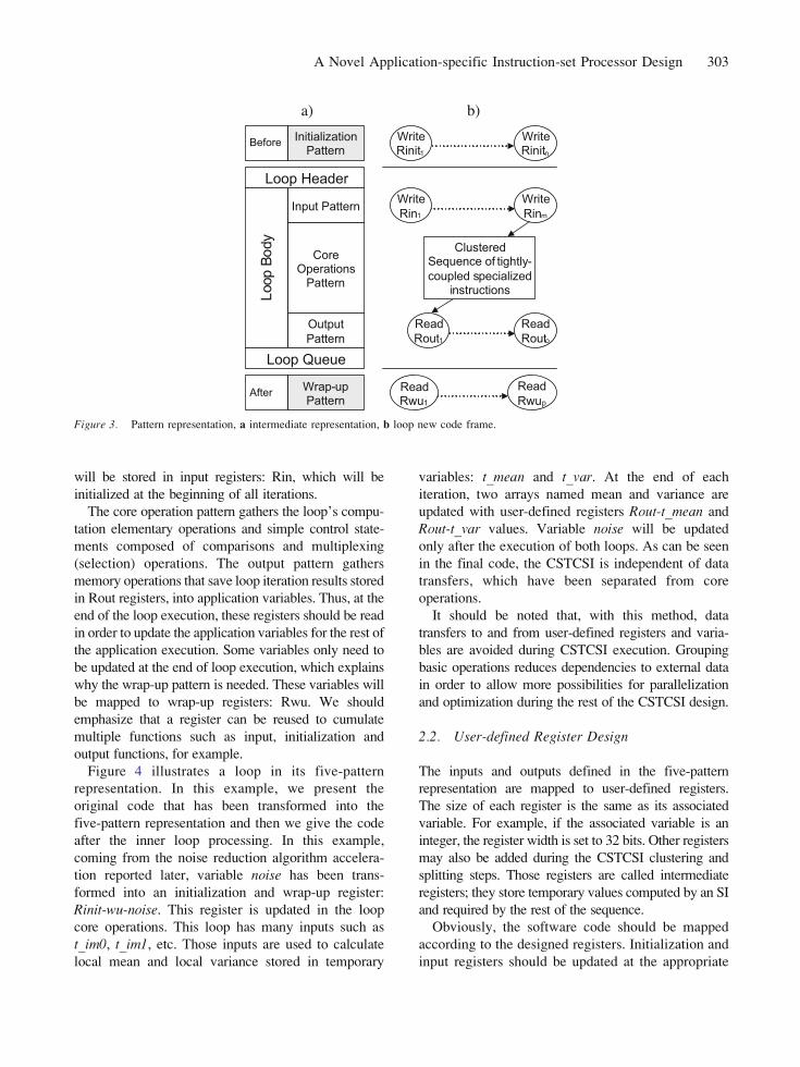
will be stored in input registers: Rin, which will be
initialized at the beginning of all iterations.
The core operation pattern gathers the loop_s compu-
tation elementary operations and simple control state-
ments composed of comparisons and multiplexing
(selection) operations. The output pattern gathers
memory operations that save loop iteration results stored
in Rout registers, into application variables. Thus, at the
end of the loop execution, these registers should be read
in order to update the application variables for the rest of
the application execution. Some variables only need to
be updated at the end of loop execution, which explains
why the wrap-up pattern is needed. These variables will
be mapped to wrap-up registers: Rwu. We should
emphasize that a register can be reused to cumulate
multiple functions such as input, initialization and
output functions, for example.
Figure 4 illustrates a loop in its five-pattern
representation. In this example, we present the
original code that has been transformed into the
five-pattern representation and then we give the code
after the inner loop processing. In this example,
coming from the noise reduction algorithm accelera-
tion reported later, variable noise has been trans-
formed into an initialization and wrap-up register:
Rinit-wu-noise. This register is updated in the loop
core operations. This loop has many inputs such as
t_im0, t_im1, etc. Those inputs are used to calculate
local mean and local variance stored in temporary
variables: t_mean and t_var. At the end of each
iteration, two arrays named mean and variance are
updated with user-defined registers Rout-t_mean and
Rout-t_var values. Variable noise will be updated
only after the execution of both loops. As can be seen
in the final code, the CSTCSI is independent of data
transfers, which have been separated from core
operations.
It should be noted that, with this method, data
transfers to and from user-defined registers and varia-
bles are avoided during CSTCSI execution. Grouping
basic operations reduces dependencies to external data
in order to allow more possibilities for parallelization
and optimization during the rest of the CSTCSI design.
2.2. User-defined Register Design
The inputs and outputs defined in the five-pattern
representation are mapped to user-defined registers.
The size of each register is the same as its associated
variable. For example, if the associated variable is an
integer, the register width is set to 32 bits. Other registers
may also be added during the CSTCSI clustering and
splitting steps. Those registers are called intermediate
registers; they store temporary values computed by an SI
and required by the rest of the sequence.
Obviously, the software code should be mapped
according to the designed registers. Initialization and
input registers should be updated at the appropriate
Input Pattern
Output
Pattern
CoreOperations
Pattern
Initialization Pattern
Wrap-up Pattern
Before
After
Loop
Bo
dy
Loop Queue
Loop Header
Write
Rinm
Clustered Sequence of tightly-
coupled specializedinstructions
Write
Rin1
Read
Rout1
Read
Routo
ReadRwu1
Read
Rwup
Write Rinitn
WriteRinit1
a) b)
Figure 3. Pattern representation, a intermediate representation, b loop new code frame.
A Novel Application-specific Instruction-set Processor Design 303

time, and output and wrap-up registers should be
read when appropriate. Otherwise, register values
will be invalid or will be erased at the next execution
of the CSTCSI.
2.3. CSTCSI Design: Operation Clusteringand Data Path Splitting
The simple clustering technique that we use, illustrated
in Fig. 5, consists of first gathering the core operations
blocks in a single SI that is then progressively split to
match the critical path to that of the basic core clock
frequency. Analysis and matching of critical paths to
maximize the clock frequency is very important, as a
key aspect of our method is to avoid reducing the
basic core frequency. Thus, the potential CSTCSIs are
compiled in order to assert the clock frequency they
can sustain and the hardware overhead they introduce.
Once the CSTCSI clock frequency is assessed,
profiling can be done in order to establish the speedup
reached by the current design. Data path splitting
creates a virtual pipeline. This pipeline is called
virtual when the steps of a CSTCSI are executed in
sequence with one feeding the other. This opens the
possibility of repeating a step more often that the
others or to make the execution of some step
conditional. Note that in some cases a single
instruction may capture all the processing needed in
the core of a loop and repeated execution of the SI are
fully pipelined. In this case the pipeline would not be
virtual. If the configurable processor is pipelined, the
sequence of TCSI will be executed through the
processor pipeline, and so the CSTCSI will run faster.
During CSTCSI clustering, intermediate registers
may be required in order to store temporary values,
as shown in Fig. 6. These registers are essential to
the splitting operation. The intermediate results held
by such registers are not accessible to the software,
but the other SIs of the sequence require them. This
is at the heart of the concept of tightly coupled
specialized instructions; it allows direct forwarding
of intermediate results from SI to SI through user-
defined registers that are available only to the SIs.
This allows maintaining a high clock rate while
avoiding the creation of bottlenecks at the input and
output of the SIs. Of course, implementing those
noise = 0;
for(row=1; row<image_height; row++)
{
for(col=1; col<image_width-1; col++)
{
t_im0 = im_src[row-1][col-1];
t_im1 = im_src[row-1][col];
t_im2 = im_src[row-1][col+1];
t_im3 = im_src[row][col-1];
t_im4 = im_src[row][col];
t_im5 = im_src[row][col+1];
t_im6 = im_src[row+1][col-1];
t_im7 = im_src[row+1][col];
t_im8 = im_src[row+1][col+1];
t_mean = t_im0 + t_im1 + … + t_im7 + t_im8;
t_var = (t_im0 * t_im0) + ... + (t_im8 * t_im8) ;
t_mean = t_mean / 9;
t_var = (t_var / 9) - (t_mean *t_mean);
mean[row][col] = t_mean;
variance[row][col] = t_var;
noise = noise + t_var;
}
}
Rin-t_im0, Rin-t_im1, ……………….…., Rin-t_im8
Rout-t_mean
t_mean = t_im0 + t_im1 + … + t_im7 + t_im8;
t_var = (t_im0 * t_im0) + ... + (t_im8 * t_im8) ;
t_mean = t_mean / 9;
t_var = (t_var / 9) - (t_mean *t_mean);
noise = noise + t_var;
Rinit-wup-noise
t_im0, t_im1, t_im2, t_im3, t_im4, t_im5, t_im6, t_im7, t_im8
noise
mean[row][col]
Write
Write
Read
Outp
ut
Basic
Opepations
Input
Loop original C code 5-Pattern Representation
Initia
lization
Wra
p-u
p
Rinit-wup-noise
noise
Read
After
During
Befo
re
Rout-t_var
variance[row][col]
Read
Write WriteWrite
Write_Rinit-wup-noise(0);
for(row=1; row<image_height; row++){
for(col=1; col<image_width-1; col++){
// Apply 2D filter
Write_t_im0(im_src[row-1][col-1]);
Write_t_im1(im_src[row-1][col]);
Write_t_im2(im_src[row-1][col+1]);
Write_t_im3(im_src[row][col-1]);
Write_t_im4(im_src[row][col]);
Write_t_im5(im_src[row][col+1]);
Write_t_im6(im_src[row+1][col-1]);
Write_t_im7(im_src[row+1][col]);
Write_t_im8(im_src[row+1][col+1]);
STCSI call
mean[row][col] = Read-t_mean();
variance[row][col] = Read-t_var();
}
}
noise = Read-Rinit-wup-noise();
Loop C code with CSTCSI
Figure 4. Example of a five-pattern representation for a loop from the Wiener filter algorithm.
304 Mbaye et al.

registers adds latency, but most of the time, it was
found to be quite cost effective. Temporary values
are stored in registers rather than being written in
temporary variables and then reloaded.
Our goal is to minimize memory transactions, thus,
during SI execution, the objective is to get a structure
where no transfer is allowed as shown in Fig. 6b. SI
intermediate results are stored in internal registers and
the next SIs should use those registers_ values. In fact, a
dataflow structure is created where each step of the
dataflow structure is an SI with a list of temporary
values stored in intermediate registers. With this
method, the application will run faster if the processor
is pipelined. In this case, the sequence of SI execution
complements the processor pipeline, which may create
a virtual pipeline.
2.4. Transformation and Parallelization
The goal of this step is to increase the number of
parallelization opportunities of the CSTCSI. It aims
at increasing the number of computations performed
in the CSTCSI. This is done by applying loop
unrolling, data grouping, and data reuse optimization
passes in order to reach our acceleration goals. The
following discussion assumes that, when SIs that are
part of a CSTCSI are in sequence, they are related by
a true data dependency. It is also assumed that such
SIs have absorbed all possible elementary operations
in an as soon as possible manner. The issue of
spreading the hardware complexity over multiple SIs
using a good scheduling that could reuse elementary
functional units is not addressed in this paper.
2.4.1. CSTCSI Unrolling. Since input data transfers
are done before the beginning of CSTCSI execution, all
data should be available for the first SI of the sequence,
thus there is no data dependency during a CSTCSI
execution. The potential for further acceleration with
CTCSI after loop unrolling depends mainly on data
dependencies between loop iterations. Such dependen-
cies are also called inter-body dependencies. Fig. 7c
shows the structure of a CSTCSI after loop unrolling,
Core operations clustering
SI Compilation
NO
YES
FSIj > Fproc_core
Software profiling
Figure 5. CSTCSI clustering process.
SI1
Output or wrap-up registers
Start of the SI sequence
End of the SI sequence
SI1
SIn
Intermediate registers
Output or wrap-up registers
Intermediate registers
Output or wrap-up registers
Output or wrap-up registers
Start of the SI sequence
End of the SI sequence
SI2
a) First specialized instruction b) Sequence of SI after N cutting operations
Figure 6. Sequence of specialized instructions before and after clustering.
A Novel Application-specific Instruction-set Processor Design 305

with an unrolling factor of m when there is no inter-
body dependency while the initial CSTCSI is illustrated
in Fig. 7a.
Loop unrolling can be applied only when the data
dependency depth [30] ddd is less than N, the number
of tightly coupled specialized instruction (TCSI) in the
sequence. If ddd is equal to or greater than N, the first
SI of the next iteration should be launched after the
current iteration execution, which precludes combin-
ing SIs from these consecutive iterations. If there is
some data dependency between the loop iterations,
ddd should be estimated. Then, according to ddd and
m, where m is the unrolling factor, a new sequence is
defined as shown in Fig. 7b, knowing that each SI
regroups elementary SIs that were defined before loop
unrolling as shown by the rectangles in the figure. Note
that, in this figure, the first and second indices of the SIs
give the SI identification number and the loop iteration
number, respectively. The two topmost elements in this
figure are the first two SIs from the first loop iteration
among the ddd SIs that must be executed before the
second iteration can start. The other SIs are replaced
with dots in the figure to make it more readable. The
next two rectangles in Fig. 7b show the first two
instructions from the group of ddd SIs that combine an
SI from the first iteration and one from the second
iteration. Again the rest of this group of ddd SIs is not
shown for clarity. At some point in the dataflow graph
Figure 7. CSTCSI unrolling and data grouping.
306 Mbaye et al.

(depending on the relative values of ddd and N), a
maximum in the number of SIs that are regrouped is
reached as illustrated by the third pair of rectangles.
Then, the number of SIs that are regrouped goes down
progressively until only the last ddd SIs from the last
iteration remain.
For example, when there is no data dependency in
a CSTCSI, unrolling is simple, since, for each step of
the sequence, the corresponding SI can be unrolled
M times. In this case, the number of cycles required
to execute the merged CSTCSI is the same as the
initial sequence, regardless of the unrolling factor.
Unrolling is applied to the initial CSTCSI rather than
unrolling the loop_s software code and then generating
the corresponding CSTCSI. The reason for this approach
is that unrolling the software code and extracting
parallelism from it would, at best, yield the same result
(i.e., lead to Fig. 7b) but it would require a lot more
computation. This does not mean that all the parallelism
in the application can be exploited by this technique.
For example, loop fusion can make explicit additional
available parallelism. Techniques of this kind can be
used on the application before the proposed method and
are therefore complementary.
2.4.2. Data Grouping in User-defined Regis-ters. CSTCSI unrolling means that more data can be
processed at the same time, thus more input operations
a)
b)
CSTCSI
dv0,1
dv0,g-1
dvx,1
dvx,g-1
dv0,1
dv0,g-1
dvy,1
dvy,g-1
new_Ri0 new_Rix
new_Ro0 new_Roy
dvx,0dv0,0
dv0,0 dvy,0
c)
j+1th
iteration
inputs
jth
iteration
outputs
dvw
CSTCSI
dv0
dv(g-1)w
dv0
dvg-1
jth
iteration
inputs
j+1th
iteration
outputs
dv1
dv(g-p)w
new_Ro0
new_Ri0 new_Rix
new_Roy
SW
SW
SW
SW
dv update by the software dv update by a SI
SI
SI
SI
SI
dv0
dvg-1
dv1
dv0
dvg-1
dv1
dv0
dvg-1
dv1
dvw
dv0
dv(g-1)w
dv(g-p)w
dvw
dv0
dv(g-1)w
dv(g-p)w
dvw
dv0
dv(g-1)w
dv(g-p)w
Shifting: dvi = dvi << (g-p)wx : Number of input registers
y: Number of output registers
dv : Data Value
j: Accelerated loop iteration
g: Number of grouped data value
p: number of reused data, with g > p
Figure 8. User-defined register design, a initial design, b with data grouping, c with data grouping and reuse.
A Novel Application-specific Instruction-set Processor Design 307

are usually required before the beginning of each
CSTCSI execution. In order to reduce the number of
data transfers, we propose to send groups of data
elements in a single block when possible. For example,
in video processing algorithms, data is composed of
pixels, thus a group of pixels can be sent in one block
rather than sending pixels one by one. In practice, this
means that, if a user-defined register was used to send
one input data per iteration as shown in Fig. 8a, then gdata elements or data values could be regrouped in one
register, as shown in Fig. 8b, where g is the number of
data values in a single register. In other words, Fig. 8b
shows each register as a group of data values displayed
on top of each other. This technique allows lowering
the number of memory transactions, since reading
simultaneously from memory 1, 2, or 4 pixels, for
example, usually incurs the same latency. Of course,
the system bus and the memory word length limit the
extent of data grouping. The process of moving data
values within registers (in order to reuse them) is
illustrated in Fig. 8c. In this figure, the two indices are
converted into one, in order to show how each register is
shifted. The label in each sub word (i.e. for each data
value) indicates the position of the first bit of the data
value. It can be seen that the bits are shifted by a number
of positions equal to (g-p)w, where g is the number of
data values, p is the number of data values that are
reused and w is the number of bits per data value.
The aim of data grouping is to feed the CSTCSI
faster. This type of operation would usually not be
efficient in a purely software code, as the processor
typically does not have the required hardware to pack
and unpack data efficiently. In a CSTCSI, bit-level data
separation is natural, whereas software code would
need costly (in terms of cycle count) bit manipulations.
2.4.3. Data Reuse. In video processing algorithms
(e.g. filtering, deinterlacing, compression), pixels are
Figure 9. Data reuse example with user-defined registers.
308 Mbaye et al.

used several times to compute different output pixels. In
most of these algorithms, computations are performed
on a moving pixel window. Thus, some of the window
pixels would be reloaded for the next iteration if a line
buffer was not used. During the CSTCSI design, an
analysis is done to detect which of the data already
stored in registers is reused at the next iteration. By a
simple register shifting operation, we avoid data reload-
ing in user-defined registers. This shifting consists of
moving data between input or initialization registers
according to data redundancy patterns, thus removing
data that is not needed anymore, as illustrated by Fig. 8c.
It can be seen in this figure that, at each iteration j, the
registers most significant bits depend on the g and pparameters, where g is the number of grouped data
values and p is the number of reused data values.
Parameter g must be strictly superior to p, otherwise
there is no possible data value to reuse. Thus, the
register_s new value, at the next iteration, will reuse
part of its old value by moving bits from location j to
j þ g � p . For example, register new_Ri0 first data
dv0,0, new value at iteration j+1 corresponds to data
value dv0,gjp at iteration j. In fact, a register_s least
significant data values, 0 to pj1, correspond to the
register_s most significant data values, p to gj1, of its
previous content. This data shifting is applied as part of
the last SI of the sequence SIn. So, during the next
iteration, only the appropriate data (register bits) will
be updated from the software.
Figure 9 gives an example where data reuse is
applied. This example comes from the Deinterlacer
algorithm [16]. In this case, data shifting was applied
on two 64-bit registers Rlinebufup and Rlinebufdown.
These registers contain eight 8-bit pixels that are used
to compute 4 pixels stored in register Rpixels_out. At
each next iteration of the algorithm, the old 32 least
significant bits (Fig. 9a) of Rlinebufup and Rlinebuf-
down registers (bits 32–63) are reused. This is done by
shifting them into the 32 most significant bits (Fig. 9b).
As shown in Fig. 9c, bits 32–63 are shifted to the MSB
positions of these registers for the next iteration.
3. Experimental Results
3.1. Benchmark Environment
The CSTCSI design methodology was applied
manually on three video processing benchmarks:
the Wiener Filter [15], the ELA Deinterlacer [16],
and the 2D-discrete cosine transform (DCT) [1].
The first two algorithms are often used in digital
television processing and the 2D-DCT is used in
JPEG coding. The original code of these algorithms
was first profiled as proposed by the framework
(Fig. 1), and their critical loops were analyzed.
Applying the proposed method to those benchmarks
produced the following results. The Wiener Filter
algorithm has two main critical loops, L1-W and L2-
W, which have inner loops, as illustrated by Table 1(a)
The ELA Deinterlacer algorithm has one main loop:
L1-De, which includes an inner loop L1_1-De, as
shown in Table 1(b). Finally, the 2D-DCT code has
three main loops, but the first two loops were merged
resulting in L12-Dct, as illustrated by Table 1(c).
During the transformation and optimization step, the
Table 2. Benchmarks_ basic core properties.
Wiener filter Deinterlacer 2D-DCT
Processor family T1050.0 T1050.4 T1050.4
Clock frequency (MHz) 100–215 135–255 135–230
Estimated gates 66,860–80,550 49,760–59,950 71,480–86,120
Cycles count (K) 47,400 34,000 12.011
Table 1. Benchmarks_ loop structure.
(a) Wiener filter (b) Deinterlacer (c) 2D-DCT
L1-W Field ..: L1-De L12-Dct
L1_1-W Field ..: L1_1-De End L12-Dct
L1_1_1-W End L1_1-De
L1_1_1_1-W End L1-De L3-Dct
End L1_1_1_1-W End L3-Dct
End L1_1_1-W
End L1_1-W
End L1-W
Apply filter: L2-W
L2_1-W
END L2_1-W
END L2-W
A Novel Application-specific Instruction-set Processor Design 309

Wiener Filter_s inner loops: L1_1_1-W and L1_1_1_1-
W were entirely unrolled. We also unrolled by a factor
of 4 the Wiener Filter and ELA Deinterlacer_s inner
loops of L1_1-W, L2_1-W, L1_1-De, and the 2D-DCT
main loops L_12-Dct and L_3-Dct. L2-Dct and L3-Dct
core operations were identical; the difference between
these two loops is their inputs and outputs, so the same
CSTCSI are to be called during their execution.
Based on this analysis, the bodies of the inner
loops of the Wiener filter were replaced with a
CSTCSI design called D2-W. It then evolved to the
D3-W design that was obtained by pipelining the
critical path of D2-W.
The Deinterlacer_s first design, D1-De, consists of
one SI that processes 4 pixels at the same time. Then,
considering the resulting execution time, speedup and
hardware overhead, we split the SI data path, which
resulted in design D2-De. Finally, D3-De was obtained
by dividing the data path of D2-De into four SIs.
In the case of the 2D-DCT loops, L1_Dct and L2-
Dct, were merged. The 2-DCT was gradually refined
into four designs, the first three, D1-Dct, D2-Dct,
and D3-Dct, correspond to refinements of the
CSTCSI obtained by gradually pipelining the SI to
match the processor clock period. Thus, D3-Dct is the
fastest design and it reaches the target performance.
These designs process 1 pixel per iteration. The last
design, D4-Dct, processes 2 pixels simultaneously.
In order to assess the quality of the results, different
reference processor cores were generated. Table 2
summarizes the benchmarks_ core characteristics. These
core properties have been used during speedup compu-
tation and analysis. For the DCT, we used a core with a
floating-point (FP) coprocessor as some steps of the
application operate on floating point numbers. The 2D-
DCT CSTSI design requires floating point numbers
conversion into fixed point, this conversion has been
done with a tool from Cantin and al. [4].
Performance and hardware complexity were assessed
using various tools. The designs were implemented
using a modified version of the Bus Functional Model
provided by Tensilica [18]. In those cases, the ASIP
and memories communicate through an AMBA bus
[3]. This 32-bit bus is used to load 4-pixel data blocks
read from an input memory and to store the computed
4-pixel output blocks to an output memory. This model
allows profiling and computing improvements in a co-
design environment. Also, the system was simulated
using the Seamless environment (a Mentor Graphics
tool) from which the profiling results were taken. SI
Figure 10. Speedup.
Figure 11. Cycle count ratio.
310 Mbaye et al.

synthesis was done with a 0.18 mm target technology.
SI Synthesis was done with Design Compiler from
Synopsys [27], in which emphasis was put on area
optimization.
3.2. Results
In the rest of this section, the main results are
presented. Performance is shown in Figs. 10 and 11
in terms of cycle count ratios and the corresponding
speedup compared to the initial code. The 2D-DCT
design D1-DCT yields a cycle count ratio of 12.51,
but its execution time speedup is only 3.58, due to its
longer critical path. That is the reason why the critical
path was split resulting in design D3-W, which yields
a computation cycle count ratio of 5.38 but an
application speedup of 6.26. Generally, a critical path
split allows increasing the achieved clock frequency.
As shown in Fig. 13, clock frequency rose from 132
MHz for D1-DCT to 267 MHz for D3-Dct.
Hardware overhead in terms of number of gates in a
design depends on the type of operations executed by
the SI and the number and size of user-defined
registers added to the processor. The Wiener Filter
and 2D-DCT designs are costly according to results
reported in Fig. 12. For example, the hardware
overhead of the Wiener Filter TCSI designs is
between 9.27 and 59.11%. These applications require
many multipliers that are relatively costly in terms of
clock frequency (Fig. 13) and number of logic gates.
The Deinterlacer does not require any multiplier and
that is why the reported hardware overheads are so
good in this case, with values less than 20%.
Since our approach targets video processing
applications, it is interesting to assess if the
developed designs reach a commonly required frame
rate (30 frames/s) and resolution (288�352 8-bit
pixels). Figure 14 reports the sustainable frame rates.
As we can see none of these applications_ original
code could reach the 30 frames/s requirements. The
Wiener Filter_s original code frame rate is equal to
3.8 frames/s, while it is 8.8 for the Deinterlacer and
3.5 frames/s for the 2D-DCT. With our approach, the
frame rate is increased above 30 frames/s with a
maximum of 47 frames/s for the Wiener Filter, 165
frames/s for the Deinterlacer and 58 frames/s for the
2D-DCT. Based on the reported performances, a
system designer can consider putting more process-
ing on the same processor while preserving real time
performance. Alternately, higher resolution image
Figure 12. SI Hardware overhead.
Figure 13. Clock frequency.
A Novel Application-specific Instruction-set Processor Design 311

formats are increasingly popular. With resolutions
and frame rate found in high definition television
(HDTV), multiple processors would be needed for
each application, in spite of the good accelerations.
These accelerations could translate into a direct
reduction of the number of processors needed to
take care of each step of a complete application in a
multi-processor system on chip (MPSOC) architecture.
Section 2.4 described, among other things, how
the proposed method implements data reuse. Table 3
shows the reduction in number of cycles associated
to load and store transactions after applying the
CSTCSI design methodology. For example, the
Deinterlacer initial number of cycles associated to
loads was 6,160,000, and it was lowered to 333,000
(Table 3); a reduction by a factor of 18.49. The 2D-
DCT benchmark initial number of cycles associated to
stores was equal to 1,691,809; after the TCSI design,
the number of clock cycles associated with stores is
reduced by a factor of 4.54. In the D3-W and D3-De
designs, every transformed loop processes and stores
four pixels per iteration, while the D4-Dct loop
processes and stores 2 pixels. These designs reach
the highest load and store reduction with a factor of
12.59 in load reduction for D3-w and 11.65 for D3-
De, for example. Thus, CSTCSI unrolling combined
with data grouping leads to significant reductions in
the number of load and store operations. In a pure
software code, data is loaded, stored and reloaded
later in the same sequence of operations. This shows
that our methodology avoids costly temporary data
loads and stores by storing temporary data in user-
defined registers as described in Section 2.4.
4. Conclusion
ASIPs are a good solution for video processing
algorithms acceleration. This family of applications
has very often been accelerated with dedicated hard-
ware modules. Typically, software implementations
running on embedded processors are not able to reach
the desired performance for an acceptable cost, size or
dissipated power. ASIPs can reach this level of
performance if they are well designed. We have
Figure 14. Frame rate.
Table 3. Number of cycles associated to loads and stores and reduction factor over the original code.
Loads
Load reduction factor
over D0 Stores
Store reduction factor
over D0
Wiener D0 11,991,458 – 3,730,037 –
D1, D2 10,781,840 1.11 2,358,203 1.58
D3 952,293 12.59 443,317 8.41
Deinterlacer D0 6,160,000 – 2,330 –
D1, D2 333,000 18.49 200 11.65
D3 333,000 18.49 200 11.65
2D-DCT D0 5,178,269 – 1,691,809 –
D1,D2 1,679,199 3.08 663,779 2.54
D3 1,565,152 3.3 85,386 1.98
D4 709,792 7.29 372,324 4.54
312 Mbaye et al.

proposed a new approach based on the development of
CSTCSI (clustered sequence of tightly coupled special-
ized instructions) for ASIP design focused on loop
acceleration. Each critical loop body is transformed
and optimized in order to increase performance, thus, it
is transformed into a sequence of tightly coupled
specialized-instructions. A five-pattern loop represen-
tation decomposing loops into initialization, input,
core, output, and wrap-up patterns was proposed to
guide the process of creating SI sequences. Such
sequences may be refined to reach higher processing
parallelism when loops are unrolled and when user-
defined registers are used to store intermediate
results between specialized instructions that compose
the sequence. Our methodology was applied to the
following video processing applications: ELA dein-
terlacing, noise reduction with Wiener filtering and
DCT calculation. These applications contain repeti-
tive set of operations and few branch statements.
Our experimental results show that, when applied to
video processing, our method provides significant
speedups, with hardware overhead much smaller
than the achieved speedups. The observed speedups
are between 12-fold and 18-fold, while hardware
overheads in terms of number of gates are between
18 and 59%. A significant contribution to the
efficiency of the proposed method is the reduction
in the number of load and store cycles associated
with data reuse and grouping. Finally, it was shown
that data communication is very costly in video
processing algorithms as it increases execution time
and power dissipation. On that matter, further work
is needed to improve data reuse by applying data
pattern analysis during the design. Another natural
extension to this research would be the automation
of the approach that would allow more design
exploration to help identify and exploit available
parallelism in the application.
References
1. L. V. Agostini, I. S. Silva, and S. Bampi, BPipelined Fast 2D
DCT Architecture for JPEG Image Compression,^ in Proc. of
the 14th Symposium on Integrated Circuits and Systems
Design, Pirenopolis, Brazil, 2001, pp. 226–231.
2. A. Aiken and A. Nicolau, BOptimal Loop Parallelization,^ in
Proc. of the SIGPLAN _88 Conference on Programming
Language Design and Implementation, Atlanta, Georgia,
USA, 1988, pp. 308–317.
3. ARM Ltd., BAmba Bus,^ available at: http://www.arm.com.
4. M.-A. Cantin, Y. Savaria, D. Prodanos, and P. Lavoie, BAn
Automatic Word Length Determination Method,^ in IEEEInternational Symposium on Circuits and Systems (ISCAS_2001)
vol. 5, Sydney, Australia, May 2001, pp. 53–56.
5. N. Cheung, J. Henkel, and S. Parameswaran, Rapid Config-
uration and Instruction Selection for an ASIP: A Case Study,DATE_03, Munich, Germany, 2003, pp. 10802–10809.
6. N. Clark, J. Blome, M. Chu, S. Mahlke, S. Biles, and K.
Flautner, BAn Framework for Transparent Instruction Set
Customization in Embedded Processors,^ in Proc. of the 32ndInternational Symposium on Computer Architecture, ISCA_05,
IEEE, Madison, Wisconsin USA, 2005, pp. 272–283.
7. J. Cong, Y. Fan, G. Han, A. Jagannathan, G. Reinman, and Z.
Zhang, Instruction Set Extension with Shadow Registers forConfigurable Processors, FPGA_05, Monterey, California,
USA, Feb. 2005, pp. 99–106.
8. CoWare, BLisatek,^ 2005, http://www.coware.com/products/
lisatek.
9. T. V. K. Gupta, R. E. Ko, and R. Barua, BCompiler-directed
Customization of ASIP Cores,^ in Proc. of 10th International
Symposium on Hadware/Software Codesign, CODES_02,
ACM, Estes Park, Colorado, USA, 2002, pp. 97–102.
10. D. Goodwin and D. Petkov, Automatic Generation of Appli-
cation Specific Processors, CASES_03, San Jose, California,
USA, 2003, pp. 137–147.
11. A. Hoffmann, T. Kogel, A. Nohl, G. Braun, O. Schliebusch,
O. Wahlen, A. Wieferink, and H. Meyr, BA Novel Method-
ology for the Design of Application-Specific Instruction-Set
Processors (ASIPs) Using a Machine Description Language,^IEEE Trans. Comput.-Aided Des. Integr. Circuits Syst., vol.
20, no. 11, Nov. 2001, pp. 1338–1354.
12. M. Imai, N. Binh, and A. Shiomi, BA New HW/SW
Partitioning Algorithm for Synthesizing the Highest Perfor-
mance Pipelined ASIPs with Multiple Identical FUs,^ in Proc.
of European Design Automation Conference, EURO-VHDL_96, Geneva, Switzerland, 1996, pp. 126–131.
13. M. K. Jain, M. Balakrishnan, and A. Kumar, An EfficientTechnique for Exploring Register File Size in ASIP Synthesis,
CASES 2002, ACM, Grenoble, France, 2002, pp. 252–261.
14. K. Karuri, M. A. Al Faruque, S. Kraemer, R. Leupers, G.
Ascheid, and H. Meyr, Fine-grained Application Source Code
Profiling for ASIP Design, ACM, DAC 2005, Anaheim,
California, USA, 2005, pp. 329–334.
15. J. S. Lim, Two-dimensional Signal and Image Processing,
Prentice-Hall, Signal Processing Series, 1990.
16. S. Lin, Y. Chang, and L. Chen, BMotion Adaptive Interpolation
with Horizontal Motion Detection for Deinterlacing,^ IEEE Trans.
Consum. Electron., vol. 49, no. 4, Nov 2003, pp. 1256–1265.
17. M. Mbaye, N. Belanger, Y. Savaria, and S. Pierre, ApplicationSpecific Instruction-set Processor Generation for Video
Processing Based on Loop Optimization, ISCAS _05, IEEE,
Kobe, Japan, May 2005, pp. 3515–3518.
18. M. Mbaye, D. Lebel, N. Belanger, Y. Savaria, and S. Pierre,
Design Exploration with an Application-specific Instruction-
set Processor for ELA Deinterlacing, ISCAS _06, IEEE, Island
of Kos, Greece, May, 2006, pp. 4607–4610.
19. H. Meyr, System-on-Chip Communications: The Dawn of
ASIPs and the Dusk of ASICs, Signal Processing Systems,
SIPS_2003, IEEE, Seoul, Korea, 2003, pp. 4–5.
A Novel Application-specific Instruction-set Processor Design 313

20. P. R. Panda, F. Cathoor, N. D. Dutt, K. Dankaert, E.
Brockmeyer, C. Kulkarni, A. Vandercapelle, and P. G.
Kjeldsberg, BData and Memory Optimization Techniques for
Embedded Systems,^ ACM Transact. Des. Automat. Electron.
Syst., vol. 6, no. 2, Apr. 2001, pp. 149–206.
21. J. Park, P. C. Diniz, and K. R. S. Shayee, BPerformance and
Area Modeling of Complete FPGA Designs in the Presence of
Loop transformations,^ IEEE Trans. Comput., vol. 53, no. 11,
Nov. 2004, pp. 1420–1435.
22. L. Pozzi and K. Atasu, BExact and Approximate Algorithms
for the Extension of Embedded Processor Instruction Sets,^IEEE Trans. Comput.-Aided Des. Integr. Circuits Syst., vol.
25, no. 7, Jul. 2006, pp. 1209–1229.
23. C. Shekhar, R. Singh, A. S. Mandal, S. C. Bose, R. Saini, and
P. Tanwar, BApplication Specific Instruction Set Processors:
Redefining Hardware–software Boundary,^ in Proc. of the
17th International Conference on VLSI Design, Mumbai,
India, 2004, pp. 915–918.
24. B. Su, S. Ding, and J. Xia, BURPR—An Extension of URCR
for Software Pipelining,^ in Proc. of the 19th Microprogram-
ming Workshop (MICRO-19), New-York, New-York, USA,
1986, pp. 94–103.
25. F. Sun, S. Ravi, A. Raghunathan, and N. K. Jha, A Scalable
Application-specific Processor Synthesis Methodology,
ICCAD_2003, San Jose, California, USA, 2003, pp. 283–290.
26. D. C. Suresh, W. A. Najjar, F. Vahid, J. R. Villarreal, and G. Stitt,
BProfiling Tools for Hardware/Software Partitioning of Embedded
Applications,^ in Proc. of the 2003 ACM SIGPLAN Conference
on Language, Compiler, and Tool for Embedded Systems(LCTES), San Diego, California, USA, 2003, pp. 189–198.
27. Synopsys Inc., BDesign Compiler,^ 2006, http://www.synopsys.com.
28. Tensilica Inc., BXtensa Processor Generator and Xpress
Compiler,^ 2006, available: http://www.tensilica.com.
29. P. Yu and T. Mitra, Characterizing Embedded Applications
for Instructions-set Extensible Processors, DAC_04, ACM,
San Diego, California, USA, 2004, pp. 723–728.
30. Wikipedia, BData dependency,^ 2007, http://en.wikipedia.org/
wiki/Data_dependency.
Mame Maria Mbaye received her B.Ing. in computer science
engineering and M.Sc.A in electrical engineering from Ecole
Polytechnique de Montreal in 2001 and 2004 respectively. She is
a Ph.D. candidate in electrical engineering at Ecole Polytechni-
que de Montreal since 2004. During her master degree, she has
worked on the design of a system-on-chip dedicated to an
Ethernet-Firewire protocol converter. Now, her research tackles
application-specific instruction-set processors design methodol-
ogy based on loop optimization and transformation. She also
works on hardware/hardware application partitioning between
specialized instructions and dedicated coprocessor generated
with high-level synthesis tool.
Normand Belanger received his B.Ing., M.Sc.A., and Ph.D.
from Ecole Polytechnique de Montreal in 1987, 1989, and
1998 respectively. After working for 6 years in industry, he
went to academia as a research assistant at Ecole Polytechni-
que de Montreal. His research interests include high perfor-
mance IC architectures, multiprocessor architectures, and
application acceleration through hardware customization.
Yvon Savaria received his B.Ing. and M.Sc.A in electrical
engineering from Ecole Polytechnique de Montreal in 1980
and 1982 respectively. He also received the Ph.D. in electrical
engineering in 1985 from McGill University. Since 1985, has
been with Ecole Polytechnique de Montreal, where he is
currently professor and director of the microelectronics
research group (www.grm.polymtl.ca).
He has carried work in several areas related to microelec-
tronic circuits and microsystems such as testing, verification,
validation, clocking methods, defect and fault tolerance, high
speed interconnects and circuit design techniques, CAD
methods, reconfigurable computing and applications of mi-
croelectronics to telecommunications, image processing video
processing, radar signal processing, and digital signal process-
ing acceleration. He holds 7 patents, has published 64 journal
papers and 280 conference papers, and he was the thesis
advisor of 110 graduate students who completed their studies.
He was the program co-chairman of the 1992 edition and the
chairman of the 1993 edition of the IEEE Workshop on Defect
and Fault Tolerance in VLSI Systems. He was program co-
314 Mbaye et al.

chairman of ASAP_ 2006 and he is general co-chair of ASAP_2007. He has been working as a consultant or was sponsored for
carrying research by CNRC, Design Workshop, DREO,
Genesis, Gennum, Hyperchip, LTRIM, Miranda, MiroTech,
Nortel, and PMC-Sierra. He is a member of the Regrouppement
Strategique en Microelectronique du Quebec (RESMIQ), of the
Micronet Canadian center of excellence on microelectronics
research, of the Ordre des Ingenieurs du Quebec (OIQ), and of
the vice-chairman of the board of CMC Microsystems. He was
awarded in 2001 a Canada Research Chair (www.chairs.qc.ca) on
design and architectures of advanced microelectronics systems. He
also received a Synergy Award of the Natural Sciences and
Engineering Research Council of Canada.
Samuel Pierre received his B.Eng. degree in Civil Engineer-
ing in 1981 from the Ecole Polytechnique de Montreal, B.Sc.
and M.Sc. degrees in mathematics and computer science in
1984 and 1985, respectively, from the Universite du Quebec,
M.Sc. degree in economics in 1987 from the Universite de
Montreal and, Ph.D. degree in Electrical Engineering in 1991
from Ecole Polytechnique de Montreal.
Dr. Pierre is currently a Professor of Computer Engineer-
ing at Ecole Polytechnique de Montreal where he is Director
of the Mobile Computing and Networking Research Labora-
tory (LARIM) and NSERC/Ericsson Industrial Research Chair
in Next-generation Mobile Networking Systems. He is the
author or co-author of 6 books, 18 book chapters, 16 edited
books, as well as over 350 other technical publications
including journal and proceedings papers. He was the thesis
advisor of 106 graduate students who completed their studies
(Masters and Ph.D. degrees). He received the Best Paper
Award of the Ninth International Workshop in Expert Systems &their Applications (France, 1989), Distinguished Paper Award
from OPNETWORK_ 2003 and OPNETWORK_ 2005
(Washington, USA), special mention from Telecoms Magazine(France, 1994) for one of his co-authored books, Telecommu-nications et transmission de donnees (Eyrolles, 1992), among
others. His research interests include wireline and wireless
networks, mobile computing, performance evaluation, artifi-
cial intelligence, and electronic learning. He is a Fellow
of Engineering Institute of Canada. He is an Associate Editor
of IEEE Communications Letters, IEEE Canadian Journal ofElectrical and Computer Engineering, and IEEE CanadianReview. He is also a Regional Editor of Journal of ComputerScience. He also serves on the editorial board of Telematicsand Informatics published by Elsevier Science, and the
International Journal of Technologies in Higher Education(IJTHE).
A Novel Application-specific Instruction-set Processor Design 315