A NONLINEAR MACRO MODEL FOR NUMERICAL … · OF EXTERIOR RC JOINTS WITHOUT TRANSVERSE REINFORCEMENT...
17
1 A NONLINEAR MACRO MODEL FOR NUMERICAL SIMULATION OF EXTERIOR RC JOINTS WITHOUT TRANSVERSE REINFORCEMENT Maria Teresa DE RISI 1 , Paolo RICCI 2 , Gerardo M. VERDERAME 3 , Gaetano MANFREDI 4 ABSTRACT In the assessment of the performance of typical existing buildings, seismic collapse safety might be significantly affected by the non-linear behaviour of the joints that are involved in the failure mechanisms because of poor structural detailing, as the lack of an adequate transverse reinforcement in the joint panel or deficiencies in the anchorage due to the absence of any capacity design principle. Few reliable approaches for modelling all sources of nonlinearity are available for poorly designed beam-column joints because of relatively poor information from experimental tests. Many nonlinear joint models are available, but most of them may be unsuitable for the assessment of older concrete buildings, either because they were developed and calibrated for confined joints or because they are complicated to use. In this study, the attention is focused on external joints with no transverse reinforcement and a preliminary exterior joint macro model is proposed. First, an experimental database of tests available in literature on joints without transverse reinforcement (and substantially homogeneous for beam bars anchorage type) that were subjected to a range of displacement histories and joint shear stress demands, and which exhibited different modes of failure (J-mode and BJ-mode failure), is collected and analyzed. Second, the joint panel constitutive parameters are defined to reproduce the experimental joint shear stress-strain relationships, when they were available. Then, bond-slip is taken into account by introducing a slip spring whose properties are calculated using a bond-slip model. Finally, the proposed joint model is validated using some of the experimental tests included in the database. INTRODUCTION Damage observed after the most recent earthquakes and experimental investigations on the seismic performance of existing Reinforced Concrete (RC) buildings highlighted the vulnerability of the beam-column joint region. The behavior of beam-column joints is a critical issue in the assessment of seismic performance of RC moment resisting frames; therefore, within the context of Performance- Based Earthquake Engineering, a growing attention should be addressed to the modelling of RC beam- 1 PhD Student, Department of Structures for Engineering and Architecture - University Federico II, Naples, [email protected] 2 PhD, Department of Structures for Engineering and Architecture - University Federico II, Naples, [email protected] 3 Assistant Professor, Department of Structures for Engineering and Architecture - University Federico II, Naples, [email protected] 4 Full Professor, Department of Structures for Engineering and Architecture - University Federico II, Naples, [email protected]
Transcript of A NONLINEAR MACRO MODEL FOR NUMERICAL … · OF EXTERIOR RC JOINTS WITHOUT TRANSVERSE REINFORCEMENT...

1
A NONLINEAR MACRO MODEL FOR NUMERICAL SIMULATION OF EXTERIOR RC JOINTS WITHOUT TRANSVERSE
REINFORCEMENT Maria Teresa DE RISI1, Paolo RICCI2, Gerardo M. VERDERAME3, Gaetano MANFREDI4
ABSTRACT
In the assessment of the performance of typical existing buildings, seismic collapse safety might be significantly affected by the non-linear behaviour of the joints that are involved in the failure mechanisms because of poor structural detailing, as the lack of an adequate transverse reinforcement in the joint panel or deficiencies in the anchorage due to the absence of any capacity design principle.
Few reliable approaches for modelling all sources of nonlinearity are available for poorly designed beam-column joints because of relatively poor information from experimental tests. Many nonlinear joint models are available, but most of them may be unsuitable for the assessment of older concrete buildings, either because they were developed and calibrated for confined joints or because they are complicated to use.
In this study, the attention is focused on external joints with no transverse reinforcement and a preliminary exterior joint macro model is proposed. First, an experimental database of tests available in literature on joints without transverse reinforcement (and substantially homogeneous for beam bars anchorage type) that were subjected to a range of displacement histories and joint shear stress demands, and which exhibited different modes of failure (J-mode and BJ-mode failure), is collected and analyzed. Second, the joint panel constitutive parameters are defined to reproduce the experimental joint shear stress-strain relationships, when they were available. Then, bond-slip is taken into account by introducing a slip spring whose properties are calculated using a bond-slip model. Finally, the proposed joint model is validated using some of the experimental tests included in the database.
INTRODUCTION
Damage observed after the most recent earthquakes and experimental investigations on the seismic performance of existing Reinforced Concrete (RC) buildings highlighted the vulnerability of the beam-column joint region. The behavior of beam-column joints is a critical issue in the assessment of seismic performance of RC moment resisting frames; therefore, within the context of Performance-Based Earthquake Engineering, a growing attention should be addressed to the modelling of RC beam- 1 PhD Student, Department of Structures for Engineering and Architecture - University Federico II, Naples, [email protected] 2 PhD, Department of Structures for Engineering and Architecture - University Federico II, Naples, [email protected] 3 Assistant Professor, Department of Structures for Engineering and Architecture - University Federico II, Naples, [email protected] 4 Full Professor, Department of Structures for Engineering and Architecture - University Federico II, Naples, [email protected]

2
column connections and the influence of failure of joints on the seismic performance of RC buildings. In particular, in the assessment of the performance of typical existing buildings, seismic
collapse safety might be significantly affected by the non-linear behaviour of the joints that are involved in the failure mechanisms because of poor structural detailing, as the lack of an adequate transverse reinforcement in the joint panel or deficiencies in the anchorage due to the absence of any capacity design principle. Such unreinforced joints are vulnerable to brittle shear failure under seismic action due to insufficient shear reinforcement in the joint region, especially for exterior joints.
In literature there is not yet a commonly accepted approach for the determination of the shear strength and for nonlinear modeling of RC beam-column joints in moment resisting RC frames. Many nonlinear joint models are available, but most of them may be unsuitable for modelling all sources of nonlinearity for the assessment of older concrete buildings, either because they were developed and calibrated for confined joints or they are complicated to implement. Moreover, the very poor dataset from experimental tests on unconfined joints makes it difficult to calibrate a comprehensive and simple nonlinear model.
In this study, the attention is focused on external joints containing no transverse reinforcement and a preliminary exterior joint macro-model is proposed. First, an experimental database of tests available in literature on joints without transverse reinforcement (and substantially homogeneous for beam bars anchorage type) that were subjected to a range of displacement histories and joint shear stress demands, and which exhibited different modes of failure (J-mode and BJ-mode failure), is collected and analyzed. Second, the joint panel constitutive parameters are defined to reproduce the experimental joint shear stress-strain relationships, when they were available. Then, bond-slip is taken into account by introducing a slip spring whose properties are analytically calculated using a bond-slip model. Finally, the proposed joint model is validated using some of the experimental tests included in the database.
STATE OF ART: JOINT MODELING FOR NUMERICAL SIMULATION
As far as the seismic behavior of RC beam-column joints under seismic loads is concerned, first of all, joint flexibility contributes significantly to the overall story drift, especially in nonlinear range. Basically, two contributions to overall deformability due to beam-column joints cannot be neglected: (i) the shear deformation of the joint panel and (ii) the contribution of the fixed-end-rotation due to the slip of the longitudinal bars anchored into the joint (e.g., Cosenza et al. 2006). Moreover, under lateral seismic loading, high shear forces are generated in the joint core. Beam-column joints bear horizontal and vertical shear forces that are usually much larger than those acting within the adjacent beams and columns. Thus, joints can experience shear failures which should be avoided by an appropriate design to ensure a ductile response of the whole frame. However, such a design does not regard typical existing structures designed for gravity loads only. In particular, exterior unreinforced RC joints often experience brittle failure under horizontal actions. Basically, two main different modes of failure can be identified: (i) J-failure, namely joint failure occurs prior to yielding of beam longitudinal reinforcement; (ii) BJ-failure, namely joint failure occurs after yielding of beam longitudinal reinforcement.
Beam-column joint shear strength As far as code prescriptions are concerned, ASCE-SEI 41 (2007) proposes recommendations for the shear strength of unreinforced joints for seismic rehabilitation purposes based on the pre-standard developed in FEMA 273 (1997) and FEMA 356 (2000). According to ASCE 41, nominal joint shear strength is defined according to Eq. (1), independent of the failure mode and the axial load ratio. The values of γn for joint shear strength are provided depending on the joint typology and the transverse reinforcement ratio ρ, as shown in Table 1.
cjcnn hbfV γ= (1)

M.T. De Risi, P. Ricci, G.M. Verderame, G. Manfredi 3
Table 1. Joint shear coefficient according to ASCE-SEI 41 (2007)
γn (MPa)0.5
ρ Interior joint with transverse beams
Interior joint w/o transverse beams
Exterior joint with transverse beams
Exterior joint w/o transverse beams
Knee joint with or w/otransverse beams
< 0.003 1.0 0.8 0.7 0.5 0.3 ≥ 0.003 1.7 1.2 1.2 1.0 0.7
Several authors have proposed analytical or empirical models to predict joint shear strength.
Thus, in literature there are different possible approaches to evaluate such a strength. Models based on the Modified Compression Field Theory (MCFT) by Vecchio and Collins
(1986), e.g. Lowes and Altoontash 2003, appeared to underestimate the shear strength of lightly reinforced joints (Shin and LaFave 2004); thus they are unsuitable for prediction of shear strength of unreinforced joints.
Other strength models proposed in literature are based on an empirical or semi-empirical approach (Bakir and Boduroglu 2002, Celik and Ellingwood 2008, Hassan 2011). Bakir and Boduroglu (2002) included the beam reinforcement ratio and the joint aspect ratio in the proposed equation for evaluating the contribution of concrete to joint shear strength, and anchorage details were included by an empirical factor. Based on the analysis of an experimental database from literature, Celik and Ellingwood (2008) proposed to evaluate the maximum joint shear strength as the joint stress corresponding to the beam or column capacity; such a strength is reduced so as not to exceed the maximum joint shear strength (statistically defined through a dataset of experimental results in a range of values with a uniform distribution), when shear failure of joint occurs before beams or columns reach their capacities. Hassan (2011) proposed an empirical strength model including the effect of joint aspect ratio and axial load ratio for J-mode of failure.
However, most of the empirical models proposed in literature have been developed based on statistical regression analysis with large scatter or small size of experimental data sets.
Other models proposed in literature for evaluating joint shear strength are the principal-tensile-stress-based models. Pauley and Priestley (1992) first proposed a comparison between the average principal tensile stress of the unconfined joint with some critical values, namely shear cracking and shear failure. Eurocode 8 (CEN 2005) and Italian provisions (D.M. 2008) adopt this approach for unreinforced joints. Other authors proposed a similar approach, introducing an upper bound of such critical values in the case of ineffective anchorage (Sharma et al. 2011) or in the case of plain bars as longitudinal reinforcement of the adjacent beam and bar end hooks (Pampanin et al. 2002). Such approaches allows to explicitly take into account the (beneficial) effect of the axial load ratio on joint shear strength, but the analysis of the experimental results – carried out on specimens with identical geometrical and mechanical properties and different axial load ratio level – showed that such an influence is quite negligible.
Moreover, the deterioration of the shear strength of beam-column joints under cyclic displacement was experimentally observed. The diagonal tension cracking of the joint core in alternative directions during seismic loading causes the reduction of the diagonal compressive strength of the concrete; therefore, the joint shear strength may degrade with the increase in ductility demand in the adjacent members during cyclic loading. Some models in literature attempted to capture this effect proposing a joint shear strength that decreases with increasing the ductility demand in the adjacent beam (Park 1997, Hakuto 2000). The relationship between the reduction of joint shear strength and the ductility factor is empirically proposed in these models, but they cannot be accurately generalized because the ductility factor is uncertain and it takes also into account the deformation of the members adjacent to the joint.
Successively, experimental tests conducted on exterior unreinforced beam-column connections aimed at the definition of the main parameters having the greatest influence on joint shear strength. Park and Mosalam (2012a) investigated the effects of three main parameters, namely (i) joint aspect ratio, (ii) beam longitudinal reinforcement ratio, and (iii) column axial load, and confirmed that joint aspect ratio and beam longitudinal tension reinforcement ratio and its strength mainly influence joint shear strength. Park and Mosalam (2012b), based on the results of parametric studies, proposed another approach to evaluate joint shear strength and its degradation after beam yielding without any ductility factor; their model directly provides a definition of the failure mode (J or BJ failure mode)

4
and it is formulated using a mechanical approach based on the strut-and-tie mechanism (Park and Mosalam, 2012b). The strut-and-tie approach was already proposed and adopted in other literature studies (Vollum and Newman 1999, Tsonos 2007). Most of the “strut-and-tie-based” models have a conceptual limitation, because the average equilibrium and compatibility equations they are based on are not suitable to reproduce the real behaviour of unreinforced beam-column joints – for which the joint shear failure is generally localized. Moreover, the accuracy of the strut-and-tie approach highly depends on the estimation of the diagonal strut area that strictly affects the joint shear strength. Nevertheless, the shear strength model proposed by Park and Mosalam (2012b) is based on a modified strut-and-tie approach, it is independent on the diagonal strut area and it shows a good agreement with experimental tests (see Table 2).
Beam-column joint modeling ASCE/SEI 41 first suggests that beam-column joint in monolithic construction should be represented as a stiff or rigid zone having horizontal dimensions equal to the column cross-sectional dimensions and vertical dimension equal to the beam depth. Successively, ASCE 41 suggests a complete backbone curve for joint shear stress-strain modeling in nonlinear analyses, but recommended values for joint shear strength coefficient and plastic shear strain for joint modeling appear to be quite conservative. Moreover, ACI 369-R11 defines an implicit beam-column joint using centerlines models with semi-rigid joint offsets: only a portion of the beam and column, or both, within the joint panel zone, is defined as rigid.
Many researchers have attempted to model the behavior of beam-column joints with different approaches, basically finite element simulations, lumped plasticity approach or multi-spring models. Some models proposed in literature may be unsuitable for older concrete building assessment, either because they were developed and calibrated for confined beam-column joints or because they are complicated to implement.
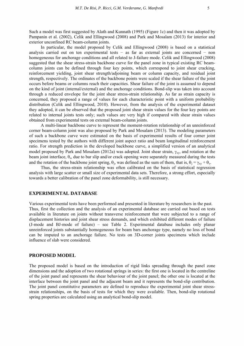
(a) (b) (c)
Figure 1. Biddah and Ghobarah (1999) multi-spring model (a); Lowes and Altoontash (1999) multi-spring model (b); Alath and Kunnath (1995) scissors model (c)
As far as multi-spring models are concerned, Biddah and Ghobarah (1999) modeled the joint with separate rotational springs for joint shear and bond–slip deformations (Figure 1a). The shear stress–strain relationship of the joint was simulated using a tri-linear idealization based on a softening truss model, while the cyclic response of the joint was captured with a hysteretic relationship with no pinching effect. Within the contest of multi-spring modeling approach, Lowes and Altoontash (2003) proposed a 4-node 12-degree-of-freedom joint element (Figure 1b). This macro-model is constituted by eight zero-length translational springs which simulate the bond-slip response of beam and column longitudinal reinforcement, a zero-length rotational spring that simulates the shear deformation of the joint, and four zero-length shear springs that simulate the interface-shear deformations. Shear stress-strain relationship of the panel zone is defined through the MCFT and, thus, joints with no transverse reinforcement were not taken into account.
Moreover, the multi-spring approach is often too difficult to implement and it requires the knowledge of multiple different contributions, which often are difficult to calibrate.
One of the simplest models, the so-called scissors model, may be very easy to implement: it is composed by a rotational spring with rigid links that take into account the finite size of the joint panel.
M.T. De Risi, P. Ricci, G.M. Verderame, G. Manfredi 5
Such a model was first suggested by Alath and Kunnath (1995) (Figure 1c) and then it was adopted by Pampanin et al. (2002), Celik and Ellingwood (2008) and Park and Mosalam (2013) for interior and exterior unconfined RC beam-column joints.
In particular, the model proposed by Celik and Ellingwood (2008) is based on a statistical analysis carried out on ten experimental tests − as far as external joints are concerned − non homogeneous for anchorage conditions and all related to J-failure mode. Celik and Ellingwood (2008) suggested that the shear stress-strain backbone curve for the panel zone in typical existing RC beam-column joints can be defined through four key points, which correspond to joint shear cracking, reinforcement yielding, joint shear strength/adjoining beam or column capacity, and residual joint strength, respectively. The ordinates of the backbone points were scaled if the shear failure of the joint occurs before beams or columns reach their capacities. Shear failure of the joint is assumed to depend on the kind of joint (internal/external) and the anchorage conditions. Bond-slip was taken into account through a reduced envelope for the joint shear stress-strain relationship. As far as strain capacity is concerned, they proposed a range of values for each characteristic point with a uniform probability distribution (Celik and Ellingwood, 2010). However, from the analysis of the experimental dataset they adopted, it can be observed that the proposed joint shear strain values for the four key points are related to internal joints tests only; such values are very high if compared with shear strain values obtained from experimental tests on external beam-column joints.
A multi-linear backbone curve to represent the moment-rotation relationship of an unreinforced corner beam-column joint was also proposed by Park and Mosalam (2013). The modeling parameters of such a backbone curve were estimated on the basis of experimental results of four corner joint specimens tested by the authors with different joint aspect ratio and beam longitudinal reinforcement ratio. For strength prediction in the developed backbone curve, a simplified version of an analytical model proposed by Park and Mosalam (2012a) was adopted. Joint shear strain, γxy, and rotation at the beam joint interface, θs, due to bar slip and/or crack opening were separately measured during the tests and the rotation of the backbone joint spring, θj, was defined as the sum of them, that is, θj = γxy + θs.
Thus, the stress-strain relationship was often calibrated on the basis of statistical regression analysis with large scatter or small size of experimental data sets. Therefore, a strong effort, especially towards a better calibration of the panel zone deformability, is still necessary.
EXPERIMENTAL DATABASE
Various experimental tests have been performed and presented in literature by researchers in the past. Thus, first the collection and the analysis of an experimental database are carried out based on tests available in literature on joints without transverse reinforcement that were subjected to a range of displacement histories and joint shear stress demands, and which exhibited different modes of failure (J-mode and BJ-mode of failure) – see Table 2. Experimental database includes only planar unreinforced joints substantially homogeneous for beam bars anchorage type, namely no loss of bond can be imputed to an anchorage failure. No tests on 3D-corner joints specimens which include influence of slab were considered.
PROPOSED MODEL
The proposed model is based on the introduction of rigid links spreading through the panel zone dimensions and the adoption of two rotational springs in series: the first one is located in the centreline of the joint panel and represents the shear behaviour of the joint panel; the other one is located at the interface between the joint panel and the adjacent beam and it represents the bond-slip contribution. The joint panel constitutive parameters are defined to reproduce the experimental joint shear stress-strain relationships, on the basis of tests for which they were available. Then, bond-slip rotational spring properties are calculated using an analytical bond-slip model.

6
Table 2. Experimental database of planar unreinforced RC beam-column joints
Reference ID specimen ν
failure mode
γn axial failure τ−γ
Loading element
Vmax,b bcol hcol bbeam hbeam fc fy,beam fy,col As,beam Lb Lc Vj
ASCE/exper Vj
P&M/exper (MPa)0.5 (kN) (mm) (mm) (mm) (mm) (MPa) (MPa) (MPa) (mm2) mm mm
Clyde et al. (2000)
2 0.10 BJ 1.07 yes yes beam 290 304.8 457.2 304.8 406 46.2 454 470 2565 1270 1080 0.46 0.98 6 0.10 BJ 1.11 yes yes beam 279 304.8 457.2 304.8 406 40.1 454 470 2565 1270 1080 0.45 0.95 4 0.25 BJ 1.14 yes yes beam 290 304.8 457.2 304.8 406 41.0 454 470 2565 1270 1080 0.44 0.93 5 0.25 BJ 1.14 yes yes beam 275 304.8 457.2 304.8 406 37.0 454 470 2565 1270 1080 0.44 0.93
Pantelides et al. (2002)
3 0.10 J 0.83 yes yes beam 187.8 406.4 406.4 406.4 406 34.0 459 470 2565 1490 1397 0.60 1.21 4 0.25 J 0.97 yes yes beam 211.4 406.4 406.4 406.4 406 31.6 459 470 2565 1490 1397 0.51 1.03 5 0.10 J 0.89 yes yes beam 194.0 406.4 406.4 406.4 406 31.7 459 470 2565 1490 1397 0.56 1.13 6 0.25 J 0.91 yes yes beam 197.6 406.4 406.4 406.4 406 31.0 459 470 2565 1490 1397 0.54 1.09
Wong (2005)
JA-NN03 0.03 BJ 0.57 no no beam 82.0 300 300 260 400 44.8 520 520 628 1500 1350 0.87 0.91 JA-NN15 0.15 BJ 0.60 no no beam 87.2 300 300 260 400 46.0 520 520 628 1500 1350 0.83 0.86 JB-NN03 0.03 BJ 0.57 no no beam 58.2 300 300 260 300 47.4 520 520 628 1500 1400 0.87 0.94
BS-L 0.15 J 0.73 no no beam 100.5 300 300 260 450 30.9 520 520 942 1500 1325 0.68 1.07 BS-L300 0.15 BJ 1.11 no no beam 95.4 300 300 260 300 34.1 520 520 942 1500 1400 0.45 0.78 BS-L600 0.15 J 0.61 no no beam 134.6 300 300 260 600 36.4 520 520 942 1500 1250 0.80 1.02
BS-U 0.15 J 0.79 no no beam 111.4 300 300 260 450 31.0 520 520 942 1500 1325 0.62 0.97 BS-L-LS 0.15 J 0.79 no no beam 110.4 300 300 260 450 31.6 520 520 942 1500 1325 0.63 0.99
Di Ludovico et al. (2012)TC2 0.21 J 0.72 no no beam 80.5 300 300 300 500 19.2 460 460 603 1650 1450 0.72 1.05 TC J 0.69 no no beam 76.5 300 300 300 500 16.4 460 460 603 1650 1450 0.70 1.02
Hwang et al (2005) OTO10 0.02 BJ 0.57 no no beam 192 420 420 320 450 67.3 430 421 2564 1900 1190 0.88 1.21
Tsonos and Papanikolau (2003)
F1 0.17 J 1.00 no no beam 60 200 200 200 300 20.0 520 520 462 900 550 0.50 0.78 F2 0.17 J 0.71 no no beam 53 200 200 200 300 31.0 530 530 383 900 550 0.70 1.05 L1 0.17 BJ 0.77 no no beam 60 200 200 200 300 34.0 520 520 616 900 550 0.65 1.02
Antonopoulos and Triantafillou (2003)
C1 0.04 J 0.78 no no beam 31.3 200 200 200 300 19.5 585 585 462 1000 500 0.64 1.01 C2 0.04 J 0.70 no no beam 31.1 200 200 200 300 23.7 585 585 462 1000 500 0.71 1.12
Genesio (2012) JT1-1 0.00 J 0.67 no no beam 76.9 300 350 300 400 25.4 560 560 829 1875 1300 0.74 1.18 JT5-1 0.00 BJ 0.60 no no beam 61.5 300 350 300 400 24.5 540 540 452 1875 1300 0.82 0.78
Uzumeri (1977) SP1 0.52 J 0.64 no no beam 102 381 381 304.8 508 30.8 347 332 1283 2350 1270 0.78 1.14 SP2 0.51 J 0.61 no no beam 97.9 381 381 304.8 508 31.1 349 335 1283 2350 1270 0.82 1.20 SP5 0.61 J 0.69 no no beam 102 381 381 381 508 26.3 352 390 1283 2350 1270 0.72 1.15
Karayannis (2008) A0 0.05 J 0.38 no no beam 25 200 200 200 300 31.6 580 580 157 1000 600 1.32 1.01 B0 0.05 J 0.58 no no beam 58 200 300 200 300 31.6 580 580 471 1000 600 0.86 1.22 C0 0.05 J 0.65 no no beam 65 200 300 200 300 31.6 580 580 452 1000 600 0.77 1.06
Mean 0.69 1.02 CoV 0.27 0.12

7
Calibration of shear stress-strain relationship of the joint panel The joint panel zone model was calibrated through tests well documented in the literature,
different for the failure mode they exhibited, namely J-failure (by Pantelides et al., 2002) and BJ-failure (by Clyde et al., 2000), for which experimental stress-strain relationships for joint panel were available.
Pantelides et al. (2000) performed cyclic tests on six full-scale models of exterior beam–column joints with two different axial load ratio levels (10% and 25% of compressive strength of concrete fc) and no transverse reinforcement within the joint core. All specimens had the same dimensions. Reinforcement bars in beam and columns were designed to prevent yielding, forcing a shear mode of failure in the joint (J-failure). Two specimens (test units 1 and 2) were designed with typical gravity load detailing and the bottom beam reinforcement bars did not have adequate embedment inside the joint. Such specimens have been excluded from the analyzed database because a loss of bond due to anchorage failure occurred. The other four specimens (test units 3, 4, 5 and 6) had both top and bottom beam bars bent into the joint. Test units 5 and 6 presented a U-hook type of anchorage for both top and bottom beam bars.
Clyde et al. (2000) performed cyclic tests on four half-scale exterior unreinforced RC beam-column joints, with two different levels of axial load on the column, namely 10% and 25% of the compressive strength of concrete (fc). All beam-column specimens had exactly the same dimensions and detailing. Both bottom and top beam reinforcements were bent up and down, respectively, into a hook in the joint. The yielding of beam longitudinal reinforcement bars before joint failure was documented by the authors (BJ-failure).
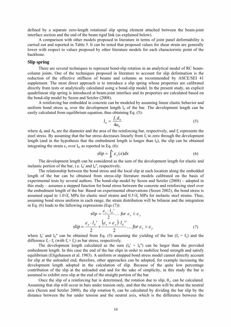
The proposed joint panel zone model is a scissors model. It can be implemented by defining duplicate nodes, node A (master) and node B (slave), with the same coordinates at the center of the joint panel. Node A is connected to the column rigid link and node B is connected to the beam rigid link. A zero length rotational spring connects the two nodes and allows only relative rotation between them through a constitutive model which represents the shear deformation of the joint panel zone. Such a rotational spring is defined as a quadrilinear Moment (Mj) – Rotation (γj) spring characterized by four points for J- and BJ-mode of failure, separately: cracking, pre-peak, peak and residual points (as shown in Figure 2).
Figure 2. Stress-strain relationship for joint panel (for J- and BJ-mode of failure)
Table 3 shows the values of shear strain and the shear stress-to-peak strength ratios (τj/τj,peak) related to the experimental tests used for the calibration of the panel zone constitutive relationship for each characteristic point of the proposed backbone. A summary of the coordinates of the characteristic points of the proposed backbone is reported in Table 4.
Cracking point The cracking point represents the onset of hairline cracks in the joint panel. Experimental tests
adopted in this study to calibrate the stress-strain shear behavior of the joint panel suggested that the corresponding shear strain (γj) is the same for J- and BJ-mode of failure and equal to 0.06%. The
0 0.5 1 1.5 2 2.5 3 3.5 40
0.1
0.2
0.3
0.4
0.5
0.6
0.7
0.8
0.9
1
γj (%)
τ j/ τj,m
ax
BJJ

8
cracking strength is evaluated in accordance to Uzumeri (1977) – which provided a good agreement with experimental data − as reported in Eq. (2):
j
ccrj APf 29.0129.0, +=τ (MPa) (2)
Pre-peak point In the case of BJ-failure the pre-peak point corresponds to the yielding of longitudinal beam
bars, thus the pre-peak strength is calculated as the joint stress corresponding to the achievement of yielding in the adjacent beam. The corresponding join shear strain obtained from tests is assumed equal to its mean value (0.26%).
In the case of J-failure, the pre-peak point corresponds to the widening of the main diagonal cracks and the developing of other cracks in the joint panel. The corresponding strength is assumed equal to 0.9 times the peak strength (defined below), in accordance with the observation of experimental tests by Pantelides et al (2002) and other models proposed in literature, e.g. Park and Mosalam (2013). The corresponding joint shear strain obtained from tests is assumed equal to its mean value (0.21%).
Peak point In the case of BJ-failure the peak point corresponds to the achievement of the flexural capacity
in the adjacent beam; in the case of J-failure this point corresponds to the achievement of the maximum shear strength specifically inherent to the joint, independently on the stress demand in the adjacent beam. As explained in the previous section, the shear strength model proposed by Park e Mosalam (2012b) directly provides a shear strength which depends on the failure typology and shows a very good agreement with experimental tests. In Table 2 a comparison between models by Park and Mosalam (2012b) and ASCE SEI-41/06 versus experimental results is reported in terms of joint strength for the experimental tests belonging to the database. It can be verified that the mean of the model-to-experimental strength ratio is closer to 1 and the CoV is lower when model by Park and Mosalam is adopted to predict shear strength with respect to the adoption of the code provision. The strength model proposed by Park e Mosalam (2012b) is adopted in this study to define the ordinate of the peak point and reported in Eq. (3):
( )⎥⎦⎤
⎢⎣
⎡=
4/coscos
πθ
cjcn hbfkV (MPa) (3)
where θ is a function of the joint aspect ratio (beam height/column height), bj and hc are the
effective joint width and the column cross-sectional height, respectively, fc is the concrete compressive strength and k is a strength factor accounting for the effect of the beam longitudinal reinforcement ratio.
The joint shear strain corresponding to the peak point obtained from tests is assumed equal to its mean value, i.e. 0.63% for BJ-failure and 0.48% for J-failure.
Residual point The softening branch is obtained by a straight line connecting the peak point and the ultimate
point provided by the authors for each experimental test. In this study, a residual strength equal to 60% or 70% of the peak strength for J-failure mode and BJ-mode is assumed, respectively. The joint shear strain corresponding to the residual point obtained from tests is assumed equal to its mean value, i.e. 3.03% for BJ-failure and 2.86% for J-failure. However, it is worth to highlight that there are very poor data regarding the achievement of this limit state and they are not always reliable because of the uncertainties in the experimental measurements for large displacement demand.
For each characteristic point of the backbone, from simple equilibrium equation, the moment
transferred through the rotational spring Mj can be obtained as a function of the joint shear stress τj through the Eq. (4):

M.T. De Risi, P. Ricci, G.M. Verderame, G. Manfredi 9
Table 3. Stress-strain relationship for joint panel for BJ- and J-mode of failure
Clyde et al. (2000) BJ-failure
test 2 test 6 test 4 test 5 min max mean min max mean
γj τj/τj,peak γj τj/τj,peak γj τj/τj,peak γj τj/τj,peak γj τj/τj,peak
cracking 0.07% 0.52 0.03% 0.31 0.11% 0.68 0.05% 0.44 0.03% 0.11% 0.06% 0.31 0.68 0.49
pre-peak 0.31% 0.94 0.18% 0.69 0.34% 1.02 0.21% 0.88 0.18% 0.34% 0.26% 0.69 1.02 0.88
peak 0.72% 1.00 0.48% 1.00 0.85% 1.00 0.48% 1.00 0.48% 0.85% 0.63% 1.00 1.00 1.00
residual 2.87% 0.53 0.75% 0.83 2.64% 0.71 5.85% 0.75 0.75% 5.85% 3.03% 0.53 0.83 0.71
Pantelides et al. (2002) J-failure
test 5 test 6 test 3 test 4 min max mean min max mean
γj τj/τj,peak γj τj/τj,peak γj τj/τj,peak γj τj/τj,peak γj τj/τj,peak
cracking 0.06% 0.54 0.08% 0.69 0.05% 0.65 0.06% 0.59 0.05% 0.08% 0.06% 0.54 0.69 0.62
pre-peak 0.23% 0.84 0.27% 0.95 0.19% 0.93 0.18% 0.92 0.18% 0.27% 0.21% 0.84 0.95 0.91
peak 0.61% 1.00 0.65% 1.00 0.33% 1.00 0.31% 1.00 0.31% 0.65% 0.48% 1.00 1.00 1.00
residual 1.96% 0.81 3.05% 0.46 4.37% 0.42 2.07% 0.68 1.96% 4.37% 2.86% 0.42 0.81 0.59
Table 4. Summary of the proposed backbone for the joint panel
J-failure BJ-failure
τ γ τ γ
cracking From Eq. (2) 0.06% From Eq. (2) 0.06%
pre-peak 0.9 τpeak 0.21% τ (Myielding,beam) 0.26%
peak From Eq. (3) 0.48% From Eq. (3) 0.63%
residual 0.6 τpeak 2.86% 0.7 τpeak 3.03% Table 5. Comparison between the proposed model and other models from literature in terms of γj
Cracking Pre-peak Peak Residual
J BJ J BJ J BJ J BJ
mean (proposed model) 0.06% 0.21% 0.26% 0.48% 0.63% 2.86% 3.03%
Celik and Ellingwood (2008) 0.01-0.13% 0.2-1.0% 1-3% 3-10%
Genesio (2012) 0.10% ‐ ‐ 0.70% 0.50% ‐ ‐ Park and Mosalam (2012a) ‐ ‐ ‐ ‐ 2εI
(+) 2εI(+) ‐ ‐
Hassan (2011)* downward τj,1/G01
0.2% 0.02% τj3/G03
0.02% τj3/G03+0.02 τj3/G03+0.025
upward 0.25% τj2/G02 τj3/G03 3% 3% (+)εI is the principal tensile strain and it depends on the joint aspect ratio. *τ
j,i is the shear stress related to the ith characteristic point; G0i is the secant stiffness to the ith characteristic point.
cb
bcjjj
LjdLh
AM
21/1
1
−−
= τ (4)
where Lb and Lc are the beam and column length, respectively, from the inflection point to the centerline of the joint panel, jdb is the beam level arm, hc the column height and Aj the effective joint area.
As far as the abscissa of the backbone is concerned, the rotation of this spring is defined equal to the joint panel rotation γj, because the joint rotation resulting from beam bar slip is explicitly
10
defined by a separate zero-length rotational slip spring element attached between the beam-joint interface section and the end of the beam rigid link (as explained below).
A comparison with other models proposed in literature in terms of joint panel deformability is carried out and reported in Table 5. It can be noted that proposed values for shear strain are generally lower with respect to values proposed by other literature models for each characteristic point of the backbone.
Slip spring There are several techniques to represent bond-slip rotation in an analytical model of RC beam-
column joints. One of the techniques proposed in literature to account for slip deformation is the reduction of the effective stiffness of beams and columns as recommended by ASCE/SEI 41 supplement. The most direct approach is to introduce a slip spring whose properties are calibrated directly from tests or analytically calculated using a bond-slip model. In the present study, an explicit quadrilinear slip spring is introduced at beam-joint interface and its properties are calculated based on the bond-slip model by Sezen and Setzler (2008).
A reinforcing bar embedded in concrete can be modeled by assuming linear elastic behavior and uniform bond stress ub over the development length ld of the bar. The development length can be easily calculated from equilibrium equation, thus obtaining Eq. (5):
b
bsd u
dfl
4= (5)
where db and Ab are the diameter and the area of the reinforcing bar, respectively, and fs represents the steel stress. By assuming that the bar stress decreases linearly from fs to zero through the development length (and in the hypothesis that the embedment length is longer than ld), the slip can be obtained integrating the strain εs over ld, as reported in Eq. (6):
∫= dl
s dxxslip0
)(ε (6)
The development length can be considered as the sum of the development length for elastic and inelastic portion of the bar, i.e. ld′ and ld″, respectively.
The relationship between the bond stress and the local slip at each location along the embedded length of the bar can be obtained from stress-slip literature models calibrated on the basis of experimental tests by several authors. The bond-slip model by Sezen and Setzler (2008) – adopted in this study – assumes a stepped function for bond stress between the concrete and reinforcing steel over the embedment length of the bar. Based on experimental observations (Sezen 2002), the bond stress is assumed equal to 1.0√fc MPa for elastic steel strains and 0.5√fc MPa for inelastic steel strains. Thus, assuming bond stress uniform in each range, the strain distribution will be bilinear and the integration in Eq. (6) leads to the fallowing expressions (Eqs (7)):
ysds for
lslip εε
ε≤
⋅= …
2'
( )
ysdysdy for
llslip εε
εεε>
⋅++
⋅= …
2''
2'
(7)
where ld′ and ld″ can be obtained from Eq. (5) assuming the yielding of the bar (fs = fy) and the difference fs - fy (with fs > fy) as bar stress, respectively.
The development length calculated as the sum (ld′ + ld″) can be larger than the provided embedment length. In this case the end of the bar slips in order to mobilize bond strength and satisfy equilibrium (Eligehausen et al. 1983). A uniform or stepped bond stress model cannot directly account for slip at the unloaded end; therefore, other approaches can be adopted, for example increasing the development length adopted in the calculation of slip. Because of the quite low percentage contribution of the slip at the unloaded end and for the sake of simplicity, in this study the bar is assumed to exhibit zero slip at the end of the straight portion of the bar.
Once the slip of a reinforcing bar is determined, the rotation due to slip, θs, can be calculated. Assuming that slip will occur in bars under tension only, and that the rotation will be about the neutral axis (Sezen and Setzler 2008), the slip rotation θs can be calculated by dividing the bar slip by the distance between the bar under tension and the neutral axis, which is the difference between the

M.T. De Risi, P. Ricci, G.M. Verderame, G. Manfredi 11
section effective depth and the neutral axis depth. In this study, θs is approximated as suggested by Otani and Sozen (1972), neglecting the slip involving the compression rebar, as reported in Eq. (8):
'dd
slips −
=θ (8)
where (d-d′) is the distance between the tensile and the compressive steel bars. As far as the definition of the quadrilinear slip spring is concerned, the first point of the spring is
identified by the beam cracking and no slip deformation is assumed; therefore, the first branch of the slip spring is a rigid branch. The second and third points are defined by beam yielding and beam flexural capacity, respectively; the corresponding θs can be calculated according to Eq. (7) and (8) assuming a bar stress which corresponds to the yielding or the flexural capacity of the beam, respectively. The forth point identifies the softening branch and it is defined from the beam softening branch. However, both in the cases of J- and BJ-failure mode, the flexural capacity of the beam is not reached; therefore, the definition of the softening branch of the slip spring is not influent.
It is worth to highlight that the fixed-end rotation becomes predominant in the joint response mainly when smooth rebars are used. Some efforts were already addressed to the detailed analysis of the force-slip relation for straight plain rebars and for different end anchorage details (Verderame et al. 2009). Nevertheless, currently, very poor experimental data about joint sub-assemblage with plain bars are available (e.g. Pampanin et al. 2002).
MODEL VALIDATION
The proposed joint model is validated using some of the experimental test included in the database. In particular eight of the tests conducted by Wong (2002) are simulated and reported in this Section: the four specimens (denominated JA-NN03, JA-NN15, JB-NN03 and BS-L300) are characterized by a BJ-failure mode; the remaining ones (denominated BS-L, BS-L600, BS-U and BS-L-LS) by a J-failure mode. The classification of the failure mode is carried out according to Park and Mosalam (2012a). Moreover, a comparison between the proposed model and other models from literature (Celik and Ellingwood 2008, Park and Mosalam 2013) is carried out; the comparison is also performed with respect to the rigid joint model and the ASCE SEI-41 model (Figure 4 and Figure 5).
The finite element analyses of the specimens were performed using OpenSees (McKenna and Fenves, 2006). The fiber approach was adopted. Figure 3 shows the structural model developed for analysis by OpenSees. Concrete and steel properties were obtained from the analyzed test reports. Concrete01 and ReinforcingSteel uniaxial materials were adopted in the modeling of nonlinear beam/column elements. The M-γ relationship for joint panel were represented through the constitutive model given in Figure 2, and implemented in OpenSees through the Pinching4 uniaxial material in a zero-length element located in the centerline of the joint. Another zero-length element was introduced at beam-joint interface for the slip spring.
Figure 3. Numerical model for beam-column joint sub-assemblages simulations
joint panel spring (Mj(τj) – γj)
fixed end rotation spring (M – θs)
nonlinear beam/column
rigid link
Δ
Lb
hc
2Lc
P

12
Figure 4. Comparisons between experimental and numerical results – J failure mode
−6 −4 −2 0 2 4 6−200
−150
−100
−50
0
50
100
150
200
Drift (%)
Bea
m L
oad
(kN
)
−6 −4 −2 0 2 4 6−200
−150
−100
−50
0
50
100
150
200
Drift (%)
Bea
m L
oad
(kN
)
−6 −4 −2 0 2 4 6−200
−150
−100
−50
0
50
100
150
200
Drift (%)
Bea
m L
oad
(kN
)
−6 −4 −2 0 2 4 6−200
−150
−100
−50
0
50
100
150
200
Drift (%)
Bea
m L
oad
(kN
)
−6 −4 −2 0 2 4 6−200
−150
−100
−50
0
50
100
150
200
Drift (%)
Bea
m L
oad
(kN
)
−6 −4 −2 0 2 4 6−200
−150
−100
−50
0
50
100
150
200
Drift (%)
Bea
m L
oad
(kN
)
−6 −4 −2 0 2 4 6−200
−150
−100
−50
0
50
100
150
200
Drift (%)
Bea
m L
oad
(kN
)
Rigid jointASCE SEI−41/06Beam yieldingexperimental
−6 −4 −2 0 2 4 6−200
−150
−100
−50
0
50
100
150
200
Drift (%)
Bea
m L
oad
(kN
)
Celik and EllingwoodPark and MosalamBeam yieldingexperimentalproposed model
WONG BSL
WONG BSL600
WONG BSLLS
WONG BSU

M.T. De Risi, P. Ricci, G.M. Verderame, G. Manfredi 13
Figure 5. Comparisons between experimental and numerical results – BJ failure mode
−6 −4 −2 0 2 4 6−150
−100
−50
0
50
100
150
Drift (%)
Bea
m L
oad
(kN
)
−6 −4 −2 0 2 4 6−150
−100
−50
0
50
100
150
Drift (%)
Bea
m L
oad
(kN
)
−6 −4 −2 0 2 4 6−150
−100
−50
0
50
100
150
Drift (%)
Bea
m L
oad
(kN
)
−6 −4 −2 0 2 4 6−150
−100
−50
0
50
100
150
Drift (%)
Bea
m L
oad
(kN
)
−6 −4 −2 0 2 4 6−150
−100
−50
0
50
100
150
Drift (%)
Bea
m L
oad
(kN
)
−6 −4 −2 0 2 4 6−150
−100
−50
0
50
100
150
Drift (%)
Bea
m L
oad
(kN
)
−6 −4 −2 0 2 4 6−150
−100
−50
0
50
100
150
Drift (%)
Bea
m L
oad
(kN
)
ASCE SEI−41/06Beam yieldingrigid jointexperimental
−6 −4 −2 0 2 4 6−150
−100
−50
0
50
100
150
Drift (%)
Bea
m L
oad
(kN
)
Celik and EllingwoodBeam yieldingPark and Mosalamproposed modelexperimental
WONG JANN03
WONG JANN15
WONG JBNN03
WONG BSL300

14
In Table 6 experimental values of elastic stiffness (kel), peak force (Fpeak) and peak drift (Δpeak) are reported for the analyzed tests; the errors related to the proposed model, and model by Celik and Ellingwood (2008) and Park and Mosalam (2013) are also reported for the positive and the negative loading directions. It can be observed that the rigid joint model generally overestimates the sub-assemblage strength, especially for J-failure mode. In this model there is no limitation of strength due to joint failure and thus the adjacent elements can develop their flexural capacity (if shear failure is prevented, as in these cases). On the contrary, for the selected tests, ASCE SEI-41 underestimates the strength (as can be verified also in Table 2) and the displacement capacity of the sub-assemblage, thus this code-approach appears to be very conservative. Celik and Ellingwood’s model was applied using the mean values of the proposed range of values for each characteristic point. This model generally overestimates maximum strength (especially in the cases of J-failure mode) and displacement capacity for the analyzed experimental tests; the proposed joint strength (0.83-1.00√MPa for exterior joints) seems to be too high. Moreover by comparing such a maximum strength with the joint stress corresponding to beam flexural capacity all of the tests should be classified as BJ-failure mode, even if some of them experienced a J-failure mode (i.e. no yielding in the adjacent beam occurred). With respect to other simulations, such a model provides also higher peak drifts because of the high values of joint drift capacity (mean of 2% at peak point) and because it allows the adjacent beam to completely develop its flexural deformability contribution until its peak strength is reached. Finally, model by Park and Mosalam captures quite well the strength of the sub-assemblages, as shown also in Table 2, but it seems to overestimate their deformability. By comparing the mean errors in Table 6, it can be observed that the proposed model conducts to lower errors in terms of initial stiffness, strength and drift capacity. Table 6. Experimental values and percentage errors (e) of elastic stiffness (kel), peak force (Fpeak) and peak drift (Δpeak) for the proposed model (Prop.), models by Celik and Ellingwood (C&E) and Park and Mosalam (P&M)
Test failure mode
kel, exper Fpeak, exper Δpeak, exper e [kel] (%) e [Fpeak] (%) e [Δpeak] (%) (kN/m) (kN) (-) Prop. C&E P&M Prop. C&E P&M Prop. C&E P&M
BS-L J Pos
17180 100.50 1.1%
-31.2 -26.2 -51.3 6.8 44.8 6.8 38.9 473.8 112.7
Neg -91.30 -1.7% 17.5 59.4 17.5 -10.7 268.9 36.7
BS-L600 J Pos
13300 134.58 1.3%
69.4 99.7 4.6 1.7 31.2 1.7 1.1 105.2 17.9
Neg -94.80 -0.7% 44.4 86.3 44.4 93.1 292.0 125.3
BS-U J Pos
10690 111.35 1.4%
10.7 18.7 -21.2 -3.5 27.3 -3.5 7.5 318.2 64.2
Neg -88.26 -1.5% 21.8 60.7 21.8 -1.6 282.7 50.2
BS-L-LS J Pos
18010 95.12 1.4%
9.4 17.2 -22.2 14.1 49.2 14.1 10.9 321.1 69.3
Neg -110.35 -1.5% -1.7 28.6 -1.7 0.7 282.2 53.7
JA-NN03 BJ Pos
7110 81.96 2.0%
71.3 79.3 17.9 -9.2 11.7 -9.2 -3.2 276.9 36.5
Neg -76.11 -1.9% -2.2 20.3 -2.2 -0.4 287.9 40.5
JA-NN15 BJ Pos
8522 87.16 1.4%
62.7 71.4 6.9 -15.3 5.4 -15.3 2.6 358.1 55.2
Neg -78.59 -1.5% -6.1 16.9 -6.1 -2.3 336.4 47.9
JB-NN03 BJ Pos
5829 58.18 2.3%
-31.1 -28.8 -48.2 -5.4 5.9 -5.4 24.5 167.7 48.8
Neg -51.57 -4.7% 6.7 19.5 6.7 -38.7 31.7 -26.8
BS-L300 BJ Pos
6915 95.40 2.7%
-25.6 -21.7 -39.6 -21.4 -11.1 -21.4 -12.9 141.3 19.5
Neg -77.57 -1.6% -4.0 8.7 -4.0 51.5 319.9 108.0
mean error Pos
16.9 26.2 -19.1 -4.0 20.6 -4.0 8.7 270.3 53.0
Neg 9.6 37.5 9.6 11.4 262.7 54.4
CONCLUSIONS
In this study, a preliminary macro-model for exterior unconfined joints with no anchorage failure has been proposed. First the adopted experimental database was presented. Second, the joint panel constitutive parameters were defined to reproduce the experimental joint shear stress-strain relationships, when they were available from tests. The proposed model for joint panel is a scissors model characterized by a quadrilinear Moment (Mj) – Rotation (γj) spring characterized by four points for J- and BJ-mode of failure, separately: cracking, pre-peak, peak and residual points. The peak
M.T. De Risi, P. Ricci, G.M. Verderame, G. Manfredi 15
strenght is evaluated according to the model by Park and Mosalam (2012a), which directly provides a shear strength depending on the failure typology and shows a very good agreement with analyzed experimental tests. Bond-slip has been taken into account by introducing an explicit slip spring (at the beam-joint interface) whose properties are analytically calculated using a simplified bond-slip model. Finally, the proposed joint model has been validated using some of the experimental tests included in the database, and a comparison between the proposed model and other models from literature and code provisions (ASCE SEI-41, Celik and Ellingwood 2008, Park and Mosalam 2013) has been carried out. It was observed that the proposed model conducts to the lower errors in terms of initial stiffness, strength and peak drift, if compared with the other models.
Further investigations shall be conducted in order to specify the proposed model in the cases of anchorage failure due to an insufficient embedment of longitudinal rebars into the joint core. Moreover, the study will be extended to the calibration of the cyclic behavior of external joints, starting from the cyclic experimental shear stress-strain response of the joint panel, when they are available. Joint axial failure should be better investigated and introduced into the model; some theoretical friction models have been already proposed in literature (Hassan, 2011); nevertheless, currently there are only a few experimental tests which reach axial failure.
REFERENCES
Alath S, Kunnath SK. (1995) “Modeling inelastic shear deformations in RC beam–column joints”. Engineering mechanics proceedings of 10th conference, May 21–24, University of Colorado at Boulder, Boulder, Colorado, vol. 2. New York: ASCE: p. 822–5.
American Concrete Institute, Committee 369, ACI 369R-11. Guide for seismic rehabilitation of existing concrete frame buildings and commentary. Feb. 2011, USA.
Antonopoulos CP and Triantafillou TC (2003) “Experimental investigation of FRP-strengthened RC beam-column joints”. Journal of composites for construction, 7(1): 39-49.
American Concrete Institute, Committee 369, ACI 369R-11. Guide for seismic rehabilitation of existing concrete frame buildings and commentary. Feb. 2011, U.S.A.
ASCE/SEI 41, Seismic rehabilitation of existing buildings. American Society of Civil Engineers, Reston, VA, USA, 2007.
Bakir PG, Boduroğlu HM (2002) “A new design equation for predicting the joint shear strength of monotonically loaded exterior beam–column joints”. Engineering Structures; 24:1105–17.
Biddah A, Ghobarah A (1999),“Modelling of shear deformation and bond slip in reinforced concrete joints”. Structural Engineering;7(4): 413–32.
Celik OC and Ellingwood BR (2008) “Modeling Beam-Column Joints in Fragility Assessment of Gravity Load Designed Reinforced Concrete Frames”, Journal of Earthquake Engineering. 12:357-381.
Celik, OC, and Ellingwood, BR (2010) “Seismic fragilities for non-ductile reinforced concrete frames–Role of aleatoric and epistemic uncertainties”, Structural Safety, 32(1): 1-12.
CEN. European standard EN 1998-3. Eurocode 8: design provisions for earthquake resistance of structures – Part 3: assessment and retrofitting of buildings. European Committee for Standardisation, Brussels, 2005.
Clyde C, Pantelides CP, Reaveley LD (2000) “Performance-Based Evaluation of Exterior Reinforced Concrete Buildings Joints for Seismic Excitation”, PEER Report, No. 2000/05, Pacific Earthquake Engineering Research Center, University of California, Berkeley, USA.
Cosenza E, Manfredi G, Verderame GM (2006) “A fibre model for push-over analysis of underdesigned reinforced concrete frames”, Computers & structures, 84(13): 904-916.
Decreto Ministeriale del 14/1/2008. Approvazione delle nuove norme tecniche per le costruzioni. G.U. n. 29 del 4/2/2008, 2008. (in Italian)
Di Ludovico M, Balsamo A, Prota A, Verderame GM, Dolce M, Manfredi G “Preliminary results of an experimental investigation on RC beam-column joints”, 6th International Conference on FRP Composites in Civil Engineering (CICE 2012), Rome, Italy, 13-15 June 2012, Paper 02-511.
Eligehausen R, Popov EP, and Bertero VV (1983) “Local Bond Stress-Slip Relationship of a Deformed Bar Under Generalized Excitations”, Report No. UCB/EERC 83/23, University of California-Berkeley, Berkeley, CA.
Federal Emergency Management Agency (1997). FEMA 273, Guidelines for the seismic rehabilitation. Washington, D.C.
Federal Emergency Management Agency (2000). FEMA 356, Prestandard and Commentary for the Seismic Rehabilitation of Buildings. Washington, D.C.

16
Genesio G (2012) Seismic assessment of RC exterior beam-column joints and retrofit with haunches using post-installed anchors. Ph.D. thesis, University of Stuttgart, Germany.
Hakuto S, Park R, Tanaka H. (2000) “Seismic load tests on interior and exterior beam–column joints with substandard reinforcing details”, ACI Structural Journal; 97(1):11–25.
Hassan WM (2011) Analytical and Experimental Assessment of Seismic Vulnerability of Beam-Column Joints without Transverse Reinforcement in Concrete Buildings, PhD Dissertation, University of California, Berkeley, California, USA.
Hwang SJ, Lee HJ. (1999) “Analytical model for predicting shear strength of exterior RC beam–column joints for seismic resistance”. ACI Structural Journal; 96(5):846–57.
Karayannis CG, and Sirkelis GM (2008) “Strengthening and rehabilitation of RC beam–column joints using carbon-FRP jacketing and epoxy resin injection”. Earthquake Engineering & Structural Dynamics, 37(5), 769-790.
Lowes LN and Altoontash A (2003) “Modeling Reinforced-Concrete Beam-Column Joints Subjected to Cyclic Loading”, Journal of Structural Engineering. 129:1686-1697.
McKenna F, Fenves GL, Scott MH (2006) “OpenSees: Open System for Earthquake Engineering Simulation”. Pacific Earthquake Engineering Research Center. University of California, Berkeley, CA, USA. http://opensees.berkeley.edu.
Otani S, and Sozen MA (1972) “Behavior of multistory reinforced concrete frames during earthquakes”. University of Illinois Engineering Experiment Station. College of Engineering. University of Illinois at Urbana-Champaign.
Pampanin S, Magenes G, Carr A (2003) “Modelling of shear hinge mechanism in poorly detailed RC beam-column joints”, Proceedings of the FIB 2003 symposium.
Pantelides CP, Hansen J, Nadauld J, Reaveley LD (2002) “Assessment of Reinforced Concrete Building Exterior Joints with Substandard Details”, PEER Report, No. 2002/18, Pacific Earthquake Engineering Research Center, University of California, Berkeley, USA.
Park R (1997) “A static force-based procedure for the seismic assessment of existing reinforced concrete moment resisting frames”. Bulletin of the New Zealand National Society for Earthquake Engineering, 30(3), 213-226.
Park S and Mosalam KM (2013),“Simulation of Reinforced Concrete Frames with Nonductile Beam-Column Joints”, Earthquake Spectra, 29(1), 233-257.
Park S, Mosalam KM, (2012a) “Parameters for shear strength prediction of exterior beam–column joints without transverse reinforcement”. Engineering Structures, 36, 198–209.
Park S, and Mosalam K.M, (2012b) “Analytical model for predicting the shear strength of unreinforced exterior beam-column joints”, ACI Structural Journal 109, 149–159.
Paulay T and Priestly M J N (1992) Seismic design of reinforced concrete and masonry buildings. John Wiley & Sons.
Sezen H (2002) Seismic behavior and modeling of reinforced concrete building columns, Ph.D. thesis, University of California, Berkeley.
Sezen H and Setzler EJ (2008) “Reinforcement slip in reinforced concrete columns”. ACI Structural Journal, 105(3).
Sharma A, Eligehausen R, Reddy GR (2011) “A new model to simulate joint shear behavior of poorly detailed beam–column connections in RC structures under seismic loads, part I: exterior joints”. Engineering Structures, 33(3), 1034-1051.
Shin M and LaFave JM (2004) “Testing and modelling for cyclic joint shear deformations in RC beam–column connections”. Proceedings of the thirteenth world conference on earthquake engineering. Paper no. 0301.
Tsonos AG (2007) “Cyclic load behaviour of reinforced concrete beam–column subassemblages of modern structures”, ACI Structural Journal; 104(4):468–78.
Tsonos AG and Papanikolaou KV (2003) "Post-Earthquake Repair and Strengthening of Reinforced Concrete Beam-Column Connections (Theoretical & Experimental Investigation)." Bulletin-New Zealand society for earthquake engineering 36.2: 73-93.
Uzumeri SM (1977) “Strength and ductility of cast-in-place beam-column joints”. From the American Concrete Institute Annual Convention, Symposium on Reinforced Concrete Structures in Seismic Zones, San Francisco, 1974. No. SP-53.
Vecchio FJ and Collins MP (1986) “The modified-compression field theory for reinforced concrete elements subjected to shear. J Amer Concr Inst;83(2):219–31.
Verderame GM, De Carlo G, Ricci P, Fabbrocino G (2009), “Cyclic bond behaviour of plain bars. Part II: Analytical investigation”. Construction and building Materials, 23(12), 3512-3522.
Vollum RL and Newman JB (1999) “Strut and tie models for analysis/design of external beam–column joints.” Mag Concr Res;51(6):415–25.

M.T. De Risi, P. Ricci, G.M. Verderame, G. Manfredi 17
Wong HF (2005) Shear strength and seismic performance of non-seismically designed RC beam–column joints. Ph.D. thesis. Hong Kong University of Science and Technology.


![Section 5.4.5 : Flood : Hazard Mitigation Plan · ... (Federal Emergency Management Agency [FEMA], 2008). ... (FEMA 1997). High groundwater ... xDeliberate acts of sabotage (terrorism);](https://static.fdocuments.net/doc/165x107/5b0276cb7f8b9a6a2e8fce97/section-545-flood-hazard-mitigation-federal-emergency-management-agency.jpg)