
A non-conventional interpretation of thermal regeneration...
10
A non-conventional interpretation of thermal regeneration in steam cycles Stefano Bracco ⇑ , Lorenzo Damiani Department of Machinery, Energy Systems and Transportation (DIMSET), University of Genova, Via Montallegro 1, 16145 Genova, Italy article info Article history: Available online 11 January 2012 Keywords: Regenerative Rankine cycle Cycle efficiency Feedwater heaters Heat pump COP abstract The paper aims to contribute to a better understanding of the thermodynamic concept of heat regener- ation in steam power plants with a finite number of bleedings. A regenerative Rankine cycle is compared to a complex system (CHC – complete hybrid cycle) composed by one non-regenerative Rankine cycle (HEC – hybrid engine cycle) and more reverse cycles (RCs – reverse cycles), as many as the number of the bleedings, able to pump heat from the condenser to a series of surface feedwater heaters, disposed upstream of the steam plant boiler. The COPs (coefficients of performance) of the heat pumps are eval- uated, and new interesting formulations of the efficiency of the regenerative steam cycle are proposed. In particular a steam cycle with two bleedings is analyzed, neglecting heat losses and pressure drops in the boiler and considering irreversibility only along the expansion line of the steam turbine and into the feedwater heaters. The efficiency and the work of the regenerative cycle are compared to the analogous values of the CHC cycle composed by one simple steam cycle (HEC) and two heat pump cycles (RCs), with steam as the working fluid. The two reverse cycles are considered completely reversible and raising heat from the condenser temperature to the bled steam condensing temperature. The paper shows the most significant results of the study in order to analyze the regenerative cycle and the CHC cycle in comparison with the non-regenerative Rankine cycle; in particular, the analysis is focused on the evaluation of the useful work, the heat supplied and the heat rejected for the examined cycles. Ó 2011 Elsevier Ltd. All rights reserved. 1. Introduction The high efficiency values reached nowadays by steam power plants are due, mainly, to two factors: improvements to materials, allowing the increase of temperatures and pressures, and thermo- dynamic cycle improvements [1–6]. Among these last, it is impor- tant to cite: the condenser vacuum decrease, the increase of the steam cycle maximum temperature and pressure, regenerative feed-heating and reheating [1–3,6–8]; the application of all these techniques allows the construction of ultra-super-critical steam power plants characterized by very high global efficiencies, near 47%, and at present there are many outstanding projects aiming at still higher efficiency values [3,6]. Certainly, in this context, a primary role is played by thermal regeneration that, as known, consists in extracting, at different pressure levels, part of the working fluid flow rate during the expansion in turbine, and using it for heating the feedwater in a train of feedwater heaters [1,2,7–15]. As well known and widely explained in literature [1,2,8,9], the advantage provided to power plant efficiency by a finite number of bleedings can be evaluated considering the following two distinct concomitant and contrast- ing thermodynamic effects of the thermal regeneration: on one side, the reduction of the sources multiplicity factor, achieved rais- ing the mean temperature of heat reception by water in the boiler; on the other side, the irreversibility introduced by the heat ex- change in heaters, characterized by a finite temperature difference between feedwater and bled steam [1,2,7,12]. As a consequence, considering the same water temperature at the boiler inlet, it is convenient to increase the number of bleedings in order to reduce the irreversibility into the feedwater heaters [1,2,7,12]. Several studies, based on this observation, lead to the conclusion that increasing the number of steam bleedings from the turbine and optimizing their pressure produces a considerable increase in the cycle thermodynamic efficiency [16–19]. The limit case is that of a ‘‘continuous regeneration’’, in which an infinite number of bleedings causes the feed-water temperature rise, analogous to the ideal case described by Haywood in [1], which consists of passing the feedwater coming from the con- denser through an infinite number of coils placed between succes- sive pairs of an infinite number of turbine stages. Both cases, obviously not realizable, are characterized by a null temperature difference between the exchanging fluids, thus the maximum effi- ciency increase coincides with the maximum sources multiplicity factor reduction; it is quite correct, of course, only if the steam is bled from the saturated zone of the turbine expansion. In this paper, the authors have faced the issue of thermal regen- eration from a non-conventional point of view, taking as reference 0306-2619/$ - see front matter Ó 2011 Elsevier Ltd. All rights reserved. doi:10.1016/j.apenergy.2011.12.047 ⇑ Corresponding author. Tel.: +39 (0) 1921945123; fax: +39 (0) 1921945104. E-mail address: [email protected] (S. Bracco). Applied Energy 97 (2012) 548–557 Contents lists available at SciVerse ScienceDirect Applied Energy journal homepage: www.elsevier.com/locate/apenergy
Transcript of A non-conventional interpretation of thermal regeneration...

Applied Energy 97 (2012) 548–557
Contents lists available at SciVerse ScienceDirect
Applied Energy
journal homepage: www.elsevier .com/ locate/apenergy
A non-conventional interpretation of thermal regeneration in steam cycles
Stefano Bracco ⇑, Lorenzo DamianiDepartment of Machinery, Energy Systems and Transportation (DIMSET), University of Genova, Via Montallegro 1, 16145 Genova, Italy
a r t i c l e i n f o a b s t r a c t
Article history:Available online 11 January 2012
Keywords:Regenerative Rankine cycleCycle efficiencyFeedwater heatersHeat pumpCOP
0306-2619/$ - see front matter � 2011 Elsevier Ltd. Adoi:10.1016/j.apenergy.2011.12.047
⇑ Corresponding author. Tel.: +39 (0) 1921945123;E-mail address: [email protected] (S. Bracco
The paper aims to contribute to a better understanding of the thermodynamic concept of heat regener-ation in steam power plants with a finite number of bleedings. A regenerative Rankine cycle is comparedto a complex system (CHC – complete hybrid cycle) composed by one non-regenerative Rankine cycle(HEC – hybrid engine cycle) and more reverse cycles (RCs – reverse cycles), as many as the number ofthe bleedings, able to pump heat from the condenser to a series of surface feedwater heaters, disposedupstream of the steam plant boiler. The COPs (coefficients of performance) of the heat pumps are eval-uated, and new interesting formulations of the efficiency of the regenerative steam cycle are proposed.
In particular a steam cycle with two bleedings is analyzed, neglecting heat losses and pressure drops inthe boiler and considering irreversibility only along the expansion line of the steam turbine and into thefeedwater heaters. The efficiency and the work of the regenerative cycle are compared to the analogousvalues of the CHC cycle composed by one simple steam cycle (HEC) and two heat pump cycles (RCs), withsteam as the working fluid. The two reverse cycles are considered completely reversible and raising heatfrom the condenser temperature to the bled steam condensing temperature. The paper shows the mostsignificant results of the study in order to analyze the regenerative cycle and the CHC cycle in comparisonwith the non-regenerative Rankine cycle; in particular, the analysis is focused on the evaluation of theuseful work, the heat supplied and the heat rejected for the examined cycles.
� 2011 Elsevier Ltd. All rights reserved.
1. Introduction
The high efficiency values reached nowadays by steam powerplants are due, mainly, to two factors: improvements to materials,allowing the increase of temperatures and pressures, and thermo-dynamic cycle improvements [1–6]. Among these last, it is impor-tant to cite: the condenser vacuum decrease, the increase of thesteam cycle maximum temperature and pressure, regenerativefeed-heating and reheating [1–3,6–8]; the application of all thesetechniques allows the construction of ultra-super-critical steampower plants characterized by very high global efficiencies, near47%, and at present there are many outstanding projects aimingat still higher efficiency values [3,6].
Certainly, in this context, a primary role is played by thermalregeneration that, as known, consists in extracting, at differentpressure levels, part of the working fluid flow rate during theexpansion in turbine, and using it for heating the feedwater in atrain of feedwater heaters [1,2,7–15]. As well known and widelyexplained in literature [1,2,8,9], the advantage provided to powerplant efficiency by a finite number of bleedings can be evaluatedconsidering the following two distinct concomitant and contrast-ing thermodynamic effects of the thermal regeneration: on one
ll rights reserved.
fax: +39 (0) 1921945104.).
side, the reduction of the sources multiplicity factor, achieved rais-ing the mean temperature of heat reception by water in the boiler;on the other side, the irreversibility introduced by the heat ex-change in heaters, characterized by a finite temperature differencebetween feedwater and bled steam [1,2,7,12]. As a consequence,considering the same water temperature at the boiler inlet, it isconvenient to increase the number of bleedings in order to reducethe irreversibility into the feedwater heaters [1,2,7,12]. Severalstudies, based on this observation, lead to the conclusion thatincreasing the number of steam bleedings from the turbine andoptimizing their pressure produces a considerable increase in thecycle thermodynamic efficiency [16–19].
The limit case is that of a ‘‘continuous regeneration’’, in whichan infinite number of bleedings causes the feed-water temperaturerise, analogous to the ideal case described by Haywood in [1],which consists of passing the feedwater coming from the con-denser through an infinite number of coils placed between succes-sive pairs of an infinite number of turbine stages. Both cases,obviously not realizable, are characterized by a null temperaturedifference between the exchanging fluids, thus the maximum effi-ciency increase coincides with the maximum sources multiplicityfactor reduction; it is quite correct, of course, only if the steam isbled from the saturated zone of the turbine expansion.
In this paper, the authors have faced the issue of thermal regen-eration from a non-conventional point of view, taking as reference
Nomenclature
Symbol Description (Units)COP coefficient of performance (–)H, h enthalpy (J/kg)L work (J)m mass (kg)Q1 heat supplied (J)Q2 heat rejected (J)R regeneration degree
Greek symbolg efficiency (–)u reciprocal of NR cycle efficiency (–)
Subscript0 condenser outlet
1 pump exit2 economiser outlet20 evaporator outlet3 superheater outlet4s, 4 steam turbine outletai feedwater heaters outlet (ax, ay)ei hydraulic turbine outlet (ex, ey)HC hybrid cyclei ith bleedingn number of bleedingsNR non-regenerativeR regenerativeRC reverse cycleT turbineX, Y bled steamx, y condensed bled steam
S. Bracco, L. Damiani / Applied Energy 97 (2012) 548–557 549
and further developing the study proposed by Bignardi and Truccoin [12] with the aim of proposing a particular intuitive method.
In particular, a regenerative steam power plant constituted by nsteam bleedings from the turbine is analyzed in order to demon-strate its equivalence, from the energy balance point of view, to a‘‘hybrid plant’’, composed by one conventional non-regenerativeRankine cycle and n heat pump cycles, carrying heat from the con-denser to the feedwater into n surface heaters. To confirm thevalidity of the study, the paper describes the main results concern-ing the energy balances of non-regenerative, regenerative and hy-brid steam cycles; in particular, the effect of different steamturbine isentropic efficiency values and the effect of the ‘‘coeffi-cient of performance’’ of the heat pumps on the plants perfor-mance are highlighted.
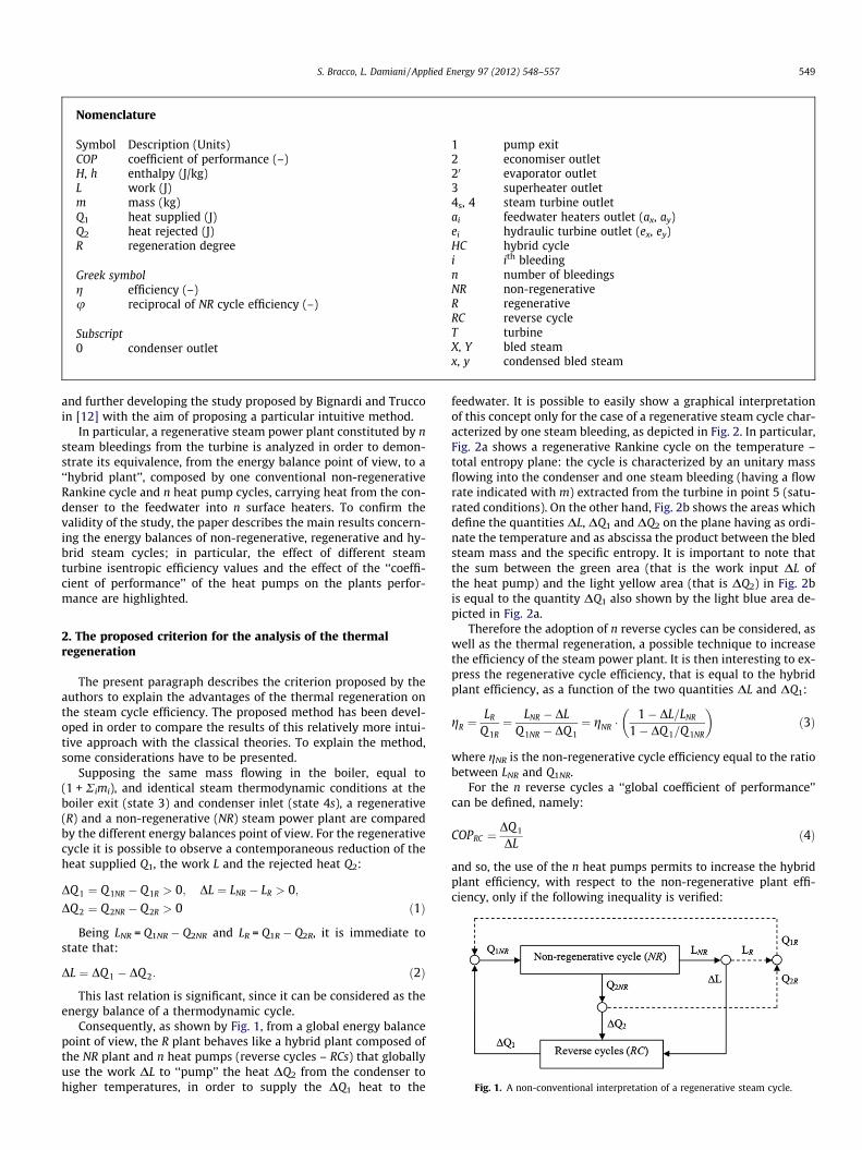
Fig. 1. A non-conventional interpretation of a regenerative steam cycle.
2. The proposed criterion for the analysis of the thermalregeneration
The present paragraph describes the criterion proposed by theauthors to explain the advantages of the thermal regeneration onthe steam cycle efficiency. The proposed method has been devel-oped in order to compare the results of this relatively more intui-tive approach with the classical theories. To explain the method,some considerations have to be presented.
Supposing the same mass flowing in the boiler, equal to(1 + Rimi), and identical steam thermodynamic conditions at theboiler exit (state 3) and condenser inlet (state 4s), a regenerative(R) and a non-regenerative (NR) steam power plant are comparedby the different energy balances point of view. For the regenerativecycle it is possible to observe a contemporaneous reduction of theheat supplied Q1, the work L and the rejected heat Q2:
DQ 1 ¼ Q 1NR � Q1R > 0; DL ¼ LNR � LR > 0;DQ 2 ¼ Q 2NR � Q2R > 0 ð1Þ
Being LNR = Q1NR � Q2NR and LR = Q1R � Q2R, it is immediate tostate that:
DL ¼ DQ 1 � DQ 2: ð2Þ
This last relation is significant, since it can be considered as theenergy balance of a thermodynamic cycle.
Consequently, as shown by Fig. 1, from a global energy balancepoint of view, the R plant behaves like a hybrid plant composed ofthe NR plant and n heat pumps (reverse cycles – RCs) that globallyuse the work DL to ‘‘pump’’ the heat DQ2 from the condenser tohigher temperatures, in order to supply the DQ1 heat to the
feedwater. It is possible to easily show a graphical interpretationof this concept only for the case of a regenerative steam cycle char-acterized by one steam bleeding, as depicted in Fig. 2. In particular,Fig. 2a shows a regenerative Rankine cycle on the temperature –total entropy plane: the cycle is characterized by an unitary massflowing into the condenser and one steam bleeding (having a flowrate indicated with m) extracted from the turbine in point 5 (satu-rated conditions). On the other hand, Fig. 2b shows the areas whichdefine the quantities DL, DQ1 and DQ2 on the plane having as ordi-nate the temperature and as abscissa the product between the bledsteam mass and the specific entropy. It is important to note thatthe sum between the green area (that is the work input DL ofthe heat pump) and the light yellow area (that is DQ2) in Fig. 2bis equal to the quantity DQ1 also shown by the light blue area de-picted in Fig. 2a.
Therefore the adoption of n reverse cycles can be considered, aswell as the thermal regeneration, a possible technique to increasethe efficiency of the steam power plant. It is then interesting to ex-press the regenerative cycle efficiency, that is equal to the hybridplant efficiency, as a function of the two quantities DL and DQ1:
gR ¼LR
Q 1R¼ LNR � DL
Q1NR � DQ 1¼ gNR �
1� DL=LNR
1� DQ 1=Q 1NR
� �ð3Þ
where gNR is the non-regenerative cycle efficiency equal to the ratiobetween LNR and Q1NR.
For the n reverse cycles a ‘‘global coefficient of performance’’can be defined, namely:
COPRC ¼DQ1
DLð4Þ
and so, the use of the n heat pumps permits to increase the hybridplant efficiency, with respect to the non-regenerative plant effi-ciency, only if the following inequality is verified:

Fig. 2. A graphical interpretation of a regenerative steam cycle characterized by one steam bleeding.
Fig. 3. Conceptual scheme of the regenerative steam power plant.
550 S. Bracco, L. Damiani / Applied Energy 97 (2012) 548–557
gR > gNR () COPRC ¼DQ 1
DL>
Q 1NR
LNR¼ 1
gNR¼ u ð5Þ
or, said in other words, only if DQ1 is higher than the heat quantityDL/gNR necessary to the non-regenerative plant to produce the workDL. It is also possible to write the quantity DQ1 as a function of thefractional enthalpy rise R (called ‘‘regeneration degree’’) and thequantity k:
DQ 1 ¼ 1þXn
i¼1
mi
!� R � k ð6Þ
where mi is the ith mass of bled steam in the R cycle and, as sug-gested in [1,2,7,12], R expresses the enthalpy range of feedwaterpre-heating non-dimensionally as a fraction of the greatest possiblepre-heating range k:
R ¼ han � h1
h2 � h1; k ¼ h2 � h1 ð7Þ
being h1 and h2 the water enthalpy values respectively at the feed-water pump exit and at the economiser outlet; moreover, han is thewater enthalpy at the boiler inlet in the R plant.
Taking into account Eq. (6) and the definition of COPRC, theregenerative cycle efficiency gR (expressed by Eq. (3)) becomes:
gR ¼1
COPRC� LNR � COPRC � ð1þ
Pni¼1miÞ � R � k
Q1NR � ð1þPn
i¼1miÞ � R � k
¼ gNR
COPRC� COPRC � ð1þ
Pni¼1miÞ � R � k � L�1
NR
1� ð1þPn
i¼1miÞ � R � k � Q�11NR
: ð8Þ
Thus, the plant efficiency dimensionless gain, due to feedwaterheating, can be calculated as:
Dgg¼ gR � gNR
gNR¼ DQ 1
Q 1R� 1� 1
gNR � COPRC
� �: ð9Þ
It derives that, a certain water mass flow entering the boiler beinggiven, the regenerative cycle efficiency gain is only a function of thecoefficient COPRC and of the ratio R, this last influencing DQ1 bymeans of Eq. (6). Moreover, for a given value of R, the plant efficiencymaximum increase is attained when the COPRC factor is maximized.
3. The regenerative steam power plant
To reinforce and apply the considerations and formulas previ-ously exposed (Section 2), these last have been applied to a regen-erative Rankine steam cycle with two feedwater heaters; thescheme of the power plant is reported in Fig. 3.
Some assumptions have been made in order to precisely controlthe energy balances. In most calculations regarding steam cyclesregeneration, the work exchanged with fluid in the liquid phaseis often neglected in energy balances, being very small with respectto that exchanged in the vapor phase. In the present calculations,instead, the work related to the liquid phase, exchanged respec-tively in the hydraulic turbines and the feedwater pump, has beenconsidered, leading to the demonstration of the energy balanceclosure also including the incompressible fluid work.
S. Bracco, L. Damiani / Applied Energy 97 (2012) 548–557 551
Going into details, the main hypotheses assumed for the pres-ent study are:
� Heat losses and pressure drops in the boiler are neglected.� All the machinery composing the power plant is considered
ideal (unitary isentropic efficiency) except the steam turbine.In fact the steam turbine efficiency gT has been varied to inves-tigate its relative influence on the monitored variables.� The feedwater heaters are assumed to have a null pinch point
temperature difference between the two fluids (infinite heatexchange area).� The steam bleedings are effected at expansion pressures suffi-
ciently low to have the point X and Y below the upper limitcurve, that is into the wet steam zone in the Mollier chart, sothat the bled streams can exchange heat with the feedwatermaintaining a constant temperature.� The feedwater heaters are dimensioned to cause bleedings com-
plete condensation without subcooling.
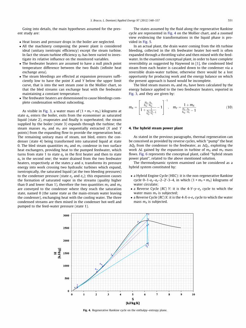
As visible in Fig. 3, a water mass of (1 + mY + mX) kilograms atstate ax enters the boiler, exits from the economiser as saturatedliquid (state 2), evaporates and finally is superheated; the steamsupplied by the boiler (state 3) expands through the turbine; thesteam masses mX and mY are sequentially extracted (X and Ypoints) from the expanding flow to provide the regeneration heat.The remaining unitary mass of steam, not bled, enters the con-denser (state 4) being transformed into saturated liquid at state0. The bled steam quantities mX and mY condense in two surfaceheat exchangers, providing heat to the pumped feedwater, whichturns from state 1 to state ay in the first heater and then to stateax in the second one; the water drained from the two feedwaterheaters, respectively at the states y and x, transforms its pressureenergy into work crossing two hydraulic turbines which expand,isentropically, the saturated liquid (at the two bleeding pressures)to the condenser pressure (state ey and ex); this expansion causesthe formation of saturated vapor in the streams (quality higherthan 0 and lower than 1), therefore the two quantities mY and mX
are conveyed to the condenser where they reach the saturationstate, named 0 (the same state as the main-stream water leavingthe condenser), exchanging heat with the cooling water. The threecondensed streams are then mixed in the condenser hot-well andpumped to the feed-water pressure (state 1).
Fig. 4. Regenerative Rankine cycle o
The states assumed by the fluid along the regenerative Rankinecycle are represented in Fig. 4 on the Mollier chart, and a zoomedview evidencing the transformations in the liquid phase is pro-vided in Fig. 5.
In an actual plant, the drain water coming from the ith turbinebleeding, collected in the ith feedwater heater hot-well is oftenexpanded through a throttling valve and then mixed with the feed-water. In the examined conceptual plant, in order to have completereversibility as suggested by Haywood in [1], the condensed bledsteam from each heater is cascaded down to the condenser via areversible drain-water turbine, otherwise there would be a lostopportunity for producing work and the energy balance on whichthe present approach is based would be incomplete.
The bled steam masses mY and mX have been calculated by theenergy balance applied to the two feedwater heaters, reported inFig. 3, and they are given by:
mX ¼HX�hx
hax�hay
1þ 1HY�hyhay�h1
�1
� 1
264
375�1
; mY ¼1þmX
HY�hy
hay�h1� 1
ð10Þ
4. The hybrid steam power plant
As stated in the previous paragraphs, thermal regeneration canbe conceived as provided by reverse cycles, which ‘‘pump’’ the heatDQ2 from the condenser to the feedwater, as DQ1, exploiting thework DL gained by the expansion in turbine of mX and mY massflows. Fig. 6 represents the conceptual plant, called ‘‘hybrid steampower plant’’, related to the above mentioned solution.
The thermodynamic system examined can be considered as ahybrid system constituted by:
� a Hybrid Engine Cycle (HEC): it is the non-regenerative Rankinecycle 0–1-ay–ax–2–20-3–4, in which (1 + mY + mX) kilograms ofwater circulate;� a Reverse Cycle (RC) Y: it is the 4-Y–y–ey cycle to which the
water mass mY is subjected;� a Reverse Cycle (RC) X: it is the 4-X-x-ex cycle to which the water
mass mX is subjected.
n the enthalpy–entropy plane.
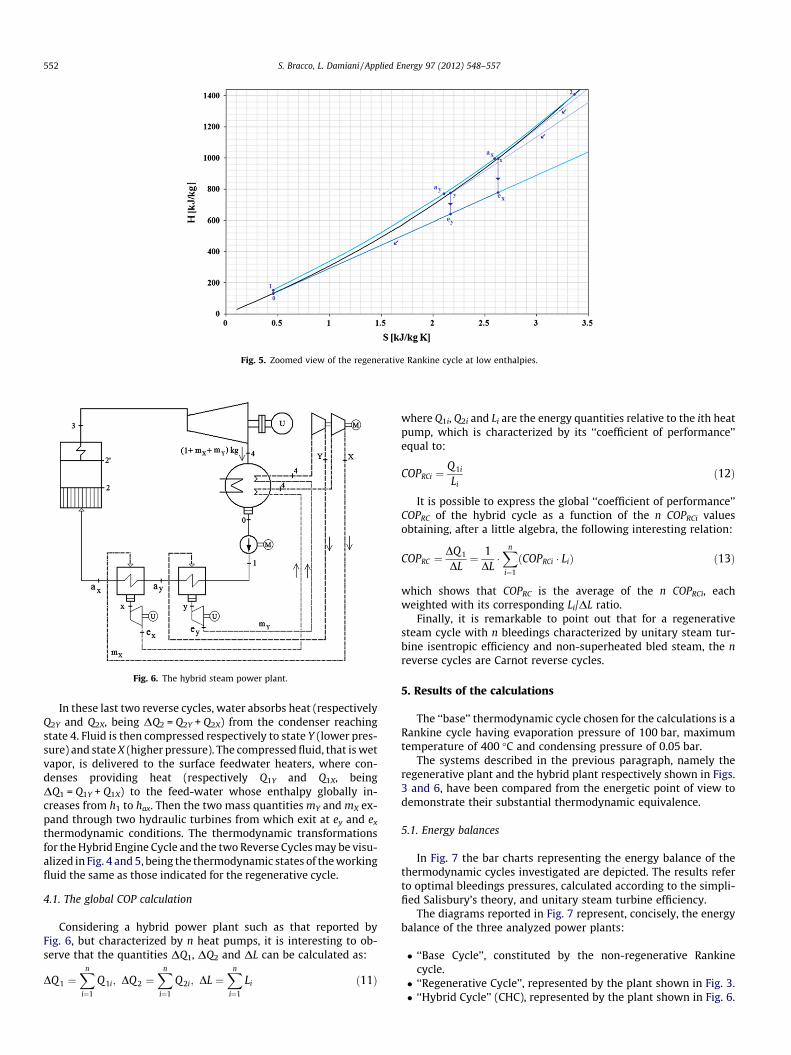
Fig. 6. The hybrid steam power plant.
Fig. 5. Zoomed view of the regenerative Rankine cycle at low enthalpies.
552 S. Bracco, L. Damiani / Applied Energy 97 (2012) 548–557
In these last two reverse cycles, water absorbs heat (respectivelyQ2Y and Q2X, being DQ2 = Q2Y + Q2X) from the condenser reachingstate 4. Fluid is then compressed respectively to state Y (lower pres-sure) and state X (higher pressure). The compressed fluid, that is wetvapor, is delivered to the surface feedwater heaters, where con-denses providing heat (respectively Q1Y and Q1X, beingDQ1 = Q1Y + Q1X) to the feed-water whose enthalpy globally in-creases from h1 to hax. Then the two mass quantities mY and mX ex-pand through two hydraulic turbines from which exit at ey and ex
thermodynamic conditions. The thermodynamic transformationsfor the Hybrid Engine Cycle and the two Reverse Cycles may be visu-alized in Fig. 4 and 5, being the thermodynamic states of the workingfluid the same as those indicated for the regenerative cycle.
4.1. The global COP calculation
Considering a hybrid power plant such as that reported byFig. 6, but characterized by n heat pumps, it is interesting to ob-serve that the quantities DQ1, DQ2 and DL can be calculated as:
DQ 1 ¼Xn
i¼1
Q 1i; DQ2 ¼Xn
i¼1
Q2i; DL ¼Xn
i¼1
Li ð11Þ
where Q1i, Q2i and Li are the energy quantities relative to the ith heatpump, which is characterized by its ‘‘coefficient of performance’’equal to:
COPRCi ¼Q1i
Lið12Þ
It is possible to express the global ‘‘coefficient of performance’’COPRC of the hybrid cycle as a function of the n COPRCi valuesobtaining, after a little algebra, the following interesting relation:
COPRC ¼DQ1
DL¼ 1
DL�Xn
i¼1
ðCOPRCi � LiÞ ð13Þ
which shows that COPRC is the average of the n COPRCi, eachweighted with its corresponding Li/DL ratio.
Finally, it is remarkable to point out that for a regenerativesteam cycle with n bleedings characterized by unitary steam tur-bine isentropic efficiency and non-superheated bled steam, the nreverse cycles are Carnot reverse cycles.
5. Results of the calculations
The ‘‘base’’ thermodynamic cycle chosen for the calculations is aRankine cycle having evaporation pressure of 100 bar, maximumtemperature of 400 �C and condensing pressure of 0.05 bar.
The systems described in the previous paragraph, namely theregenerative plant and the hybrid plant respectively shown in Figs.3 and 6, have been compared from the energetic point of view todemonstrate their substantial thermodynamic equivalence.
5.1. Energy balances
In Fig. 7 the bar charts representing the energy balance of thethermodynamic cycles investigated are depicted. The results referto optimal bleedings pressures, calculated according to the simpli-fied Salisbury’s theory, and unitary steam turbine efficiency.
The diagrams reported in Fig. 7 represent, concisely, the energybalance of the three analyzed power plants:
� ‘‘Base Cycle’’, constituted by the non-regenerative Rankinecycle.� ‘‘Regenerative Cycle’’, represented by the plant shown in Fig. 3.� ‘‘Hybrid Cycle’’ (CHC), represented by the plant shown in Fig. 6.

Fig. 7. Energy balances for the compared thermodynamic cycles: (a) Q1; (b) L; (c) Q2.
S. Bracco, L. Damiani / Applied Energy 97 (2012) 548–557 553
The Q1 diagram is presented in Fig. 7a. In accordance to Eq. (11),the heat difference DQ1 between the Q1 of the Base Cycle and theQ1 of the Regenerative Cycle is equal to the sum of the heat quan-tities (indicated in Fig. 7a as ‘‘Q1 Reverse Cycle Y’’ and ‘‘Q1 ReverseCycle X’’) provided to the feedwater by the two reverse cycles. Fur-thermore, the Q1 heat supplied to the regenerative cycle (equal to3860.9 kJ) is the same as that provided to the CHC hybrid cycle,both cycles having the same boiler inlet and outlet conditions(points ax and 3).
As previously stated in Section 4, the CHC hybrid cycle can beconsidered as the composition of three thermodynamic cycles;from this point of view, the Q1 amount supplied to the ‘‘Hybrid En-gine Cycle’’ (equal to 5446.7 kJ) can be considered as the heat pro-vided in the boiler (indicated in the figure as ‘‘Q1 Complete HybridCycle’’) plus the heat provided by the two heat pump cycles (‘‘Q1
Reverse Cycle Y’’ and ‘‘Q1 Reverse Cycle X’’). It is important to pointout that the Q1 amounts of the two reverse cycles are equal(792.9 kJ), as stated by the Salisbury’s theory according to whichthe enthalpy rise has to be the same in all feedwater heaters [1,7].
The calculated work L for each cycle is shown in Fig. 7b. Asproved for DQ1, the work difference DL between the L of the BaseCycle and the L of the Regenerative Cycle, is equal to the sum of thework inputs of the ‘‘Reverse Cycle Y’’ and the ‘‘Reverse Cycle X’’.
The net work of the Complete Hybrid Cycle (equal to 1682.1 kJ)can be calculated by subtracting the work inputs of the two heat-pumps (‘‘L Reverse Cycle Y’’ equal to 196.2 kJ and ‘‘L Reverse CycleX’’ equal to 309.8 kJ) from the work output of the Hybrid EngineCycle (equal to 2188.1 kJ). The ‘‘Reverse Cycle X’’ has a work inputhigher than that absorbed by the ‘‘Reverse Cycle Y’’ since it is char-acterized by a higher pressure at the compressor discharge and soby a lower COP.
The rejected heat Q2 has also been analyzed, and the results arecompatible with those of Q1 and L. A part of the heat rejected by
the ‘‘Hybrid Engine Cycle’’ constitutes the heat input of the two re-verse heat pump cycles, equal to DQ2.
5.2. Parametric analysis
Several tests have been carried out to determine the variation ofthe regenerative plant main parameters as a function of the bleed-ings pressure values. In particular, the tests have been conductedmaintaining constant the pressure of the first bleeding (pX), andvarying the pressure of the second bleeding (pY). The following dia-grams, representing the monitored variables, have in abscissa thepartial degree of regeneration RY = (hay – h1)/k.
Fig. 8 shows the steam masses (mY and mX) as a function of RY.Different curves have been sketched varying the turbine isentropicefficiency gT from 0.86 to 1. As visible, the two quantities mY andmX are almost the same when RY is equal to ca. 0.33 (Salisbury’soptimal condition) and, for a given RY, they increase with gT.
Figs. 9–11 represent the regenerative power plant energy flowsQ1, L and Q2 normalized with respect to their values Q1opt, Lopt andQ2opt, calculated considering the Salisbury optimal values for pY
and pX, diagrammed as a function of RY. Also in this case, differentturbine efficiencies gT in the range [0.86;1] have been considered.
As visible in Figs. 9–11, Q1/Q1_opt and L/Lopt curves show a cer-tain spread, for the different isentropic turbine efficiencies, farfrom the condition RY = 0.33, whereas Q2/Q2_opt curves display asmaller variation with gT.
Fig. 12 reports the regenerative cycle efficiency, equal to that ofthe complete hybrid cycle, as a function of RY for the various tur-bine efficiency values. Obviously, lower turbine efficiencies corre-spond to lower cycle efficiencies and, for all the curves, themaximum efficiency is set at about RY equal to 0.29, lower thanthe optimal Salisbury value (0.33). This is mainly imputable tothe fact that the simplified analytical Salisbury’s theory is formu-

Fig. 8. Bled steam quantities as a function of RY.
Fig. 9. The Q1/Q1opt ratio as a function of RY.
Fig. 10. The L/Lopt ratio as a function of RY.
554 S. Bracco, L. Damiani / Applied Energy 97 (2012) 548–557

Fig. 11. The Q2/Q2opt ratio as a function of RY.
Fig. 12. The regenerative and CHC cycles efficiencies as a function of RY.
S. Bracco, L. Damiani / Applied Energy 97 (2012) 548–557 555
lated in the hypothesis of considering contact feedwater heatersand, at any bleeding pressure, a constant enthalpy difference be-tween bled steam and saturated liquid; moreover, the work re-lated to machinery elaborating incompressible fluid is not takeninto account. Evidently, overtaking these simplifications leads todifferent results.
In Fig. 13 the COP values for the two Reverse Cycles X and Y con-stituting the hybrid plant are graphed as a function of RY and gT. Byhypothesis, the Reverse Cycle X operates at a constant pressure,therefore its COP value remains constant. Instead, the COP of theReverse Cycle Y changes with RY, and so with pY, assuming veryhigh values for pY approaching the condenser pressure; as pY tendsto pX, COPY tends to COPX. These observations are in accordancewith reverse cycles theories, for which a reverse cycle operatingbetween two very close temperature values is characterized by avery high COP.
The global COP, calculated as a function of COPX and COPY by Eq.(13), is shown in Fig. 14. The global COP has maximum values, forall the expansion efficiency curves, at RY almost equal to 0.29, asfound for the maximum efficiency of the regenerative Rankine cy-cle. Fig. 14 also displays the u values that, in accordance with Eq.(5), are the reciprocal values of the non-regenerative cycle effi-
ciency; as visible in Fig. 14, the inequality reported in Eq. (5) is al-ways satisfied.
5.3. A possible application
A possible application of the presented theory to the industrialreality could be feasible for the small electrical power productionplants. These ones are seldom regenerated, due to the increase incomplexity and costs that thermal regeneration would imply. Nev-ertheless, in some cases, a pressurized fluid reservoir at equilib-rium conditions is needed, above all for degassing purposes. Toavoid the solution of a steam bleeding from the turbine, whichwould require the customization (and therefore the increase incosts) of the turbomachinery, one solution could be a live steambleeding, as represented in Fig. 15a (on the left). Obviously, thissolution would not increase the plant efficiency.
The data reported in Fig. 15 are referred to a calculation made inthe hypothesis of utilizing a Fincantieri MS–VS turbine, withoutsteam bleedings, for power production.
As an alternative to the live steam bleeding, a solution consistingin a hybrid steam plant with a water heat pump reverse cycle,pumping heat from the condenser to the hot fluid reservoir, might

Fig. 13. The reverse cycles COP values as a function of RY.
Fig. 14. Global COP and as a function of RY.
Fig. 15. A possible application of the presented theoretical method to an existing small power plant: (a) conventional solution and (b) solution with heat pump from thecondenser.
556 S. Bracco, L. Damiani / Applied Energy 97 (2012) 548–557
be considered, as shown by Fig. 15b. In this case, an increase in theplant efficiency is expected, as shown in Table 1, in which the
overall performances of the conventional and of the hybrid plantsare presented.

Table 1Performances of the live steam bleeding and hybrid power plants.
Conventional solution(Fig. 15a)
Solution with heat pump(Fig. 15b)
Turbine power 4577.49 kW 5078.18 kWPumps power 35.07 kW 35.16 kWHeat pump
compressor power– 421.71 kW
Thermal power input 13463.78 kW 13463.78 kWEfficiency 0.337 0.343
S. Bracco, L. Damiani / Applied Energy 97 (2012) 548–557 557
The hybrid plant efficiency increase is not certainly large en-ough to justify the increase in capital costs (mainly due to thesteam compressor, characterized by a significant volumetric flowrate) determined by the heat pump installation. However, the pres-ent study is not aimed at estimating the feasibility of a possibleinstallation from the economic point of view; the investigation ofdifferent working fluids for the heat pump might be an interestingdevelopment of the present study, in order to find a technical solu-tion able to reduce the volumetric flow rate in the heat pumps and,consequently, the compressor capital cost.
6. Conclusion
In the presented paper, the authors have proposed a non-conventional approach to face the technique of thermal regenera-tion, a powerful mean to increase the efficiency of steam powerplants. This approach allows to analyze, from the thermodynamicpoint of view, a regenerative Rankine cycle as a hybrid power plantconstituted by one Rankine cycle without steam bleedings and nheat pumps that contribute to the feedwater enthalpy rise.
To validate the developed theoretical relations, the analysis of aregenerative steam cycle has been carried out, applying the pro-posed theory to a Rankine cycle with two steam bleedings. Theapplication includes the study of the plant energy balances takinginto account different values of the turbine isentropic efficiencyand not neglecting the work of incompressible fluid machinery.The presented approach has allowed the authors to draw several
interesting results and considerations on the COP of the global heatpump system and to propose some hints for a possible application.
References
[1] Haywood RW. Analysis of engineering cycle. Oxford, England: Pergamon Press;1991.
[2] Caputo C. Energy conversion systems. Milano, Italy: Casa Editrice Ambrosiana;2001.
[3] Cziesla F, Bewerunge J, Senzel A. Lünen – state of the art USC steam powerplant under construction. In: Proc of Power-Gen Europe 2009; Cologne,Germany.
[4] Torre A, Maretto L, Zannoni M. Advanced steam turbine design and materialsfor coal fired power plants applications. In: Proc of Power-Gen Europe 2005.
[5] Stamatelopoulos GN, Sadlon E. Advancement in coal-fired power plants:higher efficiency using advanced materials. In: Proc of Power-Gen Europe2005.
[6] Blum R, Bugge J, Kjær S. AD700 innovations pave the way for 53% efficiency.Modern Power Systems; November 2008.
[7] Salisbury JK. Steam turbines and their cycles. New York: John Wiley & Sons,Inc.; 1950.
[8] Zoeb H. Steam turbines – theory and design. New Delhi: Tata Mc-Graw-HillPublishing Company Limited; 1984.
[9] Moran MJ, Shapiro HN. Fundamentals of engineering inthermodynamics. England: John Wiley & Sons; 2006.
[10] Caputo C. A figure of merit for thermodynamic cycles. Il Calore, No. 7/1967.[11] Arrighetti C. On the thermal regeneration in steam power plants. La
Termotecnica; 1969.[12] Bignardi L, Trucco A. On the thermodynamic analysis of thermal regeneration
in steam power plants. Il Calore, No. 9/1973.[13] Bignardi L. About thermal regeneration of steam power plants. La Marina
Italiana; 1968.[14] Tchanche BF, Lambrinos G, Frangoudakis A, Papadakis G. Exergy analysis of
micro-organic Rankine power cycles for a small scale solar driven reverseosmosis desalination system. Appl Energy 2010;87(4):1295–306.
[15] Sterman LS, Tevlin SA, Sharkov AT. Thermal and nuclear power stations. MirPublishers; 1986.
[16] Habib MA, Said SAM, Al-Zaharma I. Thermodynamic optimization of reheatregenerative thermal power plants. Appl Energy 1999;63:17–34.
[17] Srinivas T, Gupta AVSSKS, Reddy BV. Generalized thermodynamic analysis ofsteam power cycles with n number of feedwater heaters. Int J Thermodynam2007;10(4):177–85.
[18] Dincer I, Al-Muslim H. Thermodynamic analysis of reheat cycle steam powerplants. Int J Energy Res 2001;25:727–39.
[19] Farhad S, Saffar-Avval M, Younessi-Sinaki M. Efficient design of feedwaterheaters network in steam power plants using pinch technology and exergyanalysis. Int J Energy Res 2008;32:1–11.