
A New Thermoplastic Composite - Subsea UK van onna subsea 2011 present… · A New Thermoplastic...
23
Transcript of A New Thermoplastic Composite - Subsea UK van onna subsea 2011 present… · A New Thermoplastic...
A New Thermoplastic Composite Riser for Deepwater Application
Martin van Onna, Managing Director Airborne Composite Tubulars
Patrick O’Brien, Group Director Strategic Business & Marketing, Wood Group Kenny
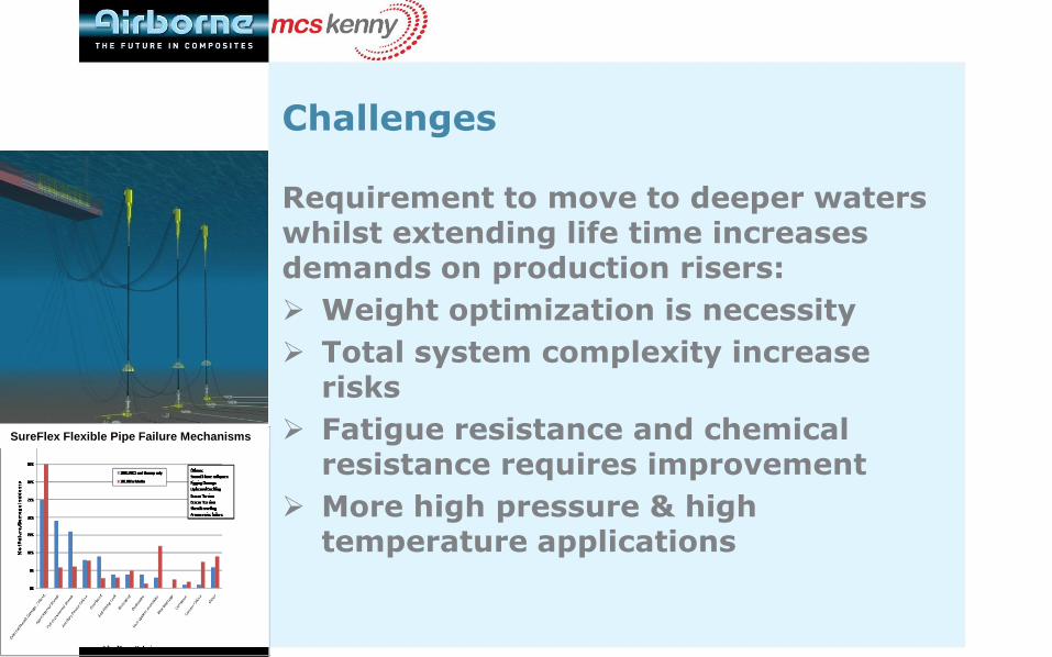
Challenges
Requirement to move to deeper waters whilst extending life time increases demands on production risers:
Weight optimization is necessity
Total system complexity increase risks
Fatigue resistance and chemical resistance requires improvement
More high pressure & high temperature applications
SureFlex Flexible Pipe Failure Mechanisms

Solution
1. Thermoplastic Composite PipeTechnology
2. Integrated Development Approachincluding pipe design and globalriser system analysis
3. Technology Acceptance Plan
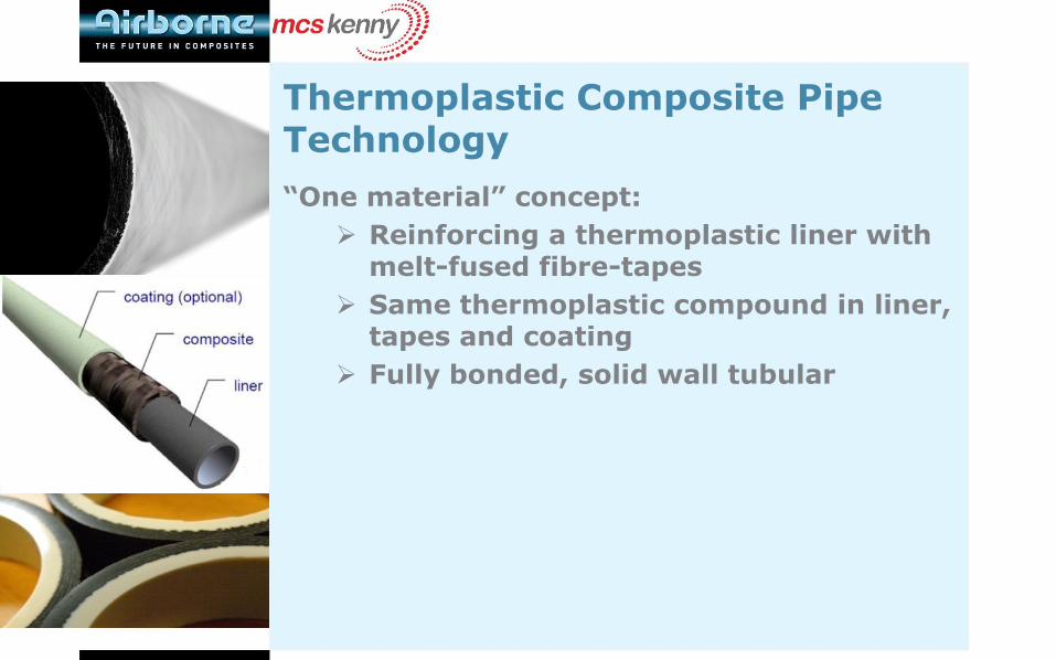
Thermoplastic Composite Pipe Technology
“One material” concept:
Reinforcing a thermoplastic liner with melt-fused fibre-tapes
Same thermoplastic compound in liner, tapes and coating
Fully bonded, solid wall tubular
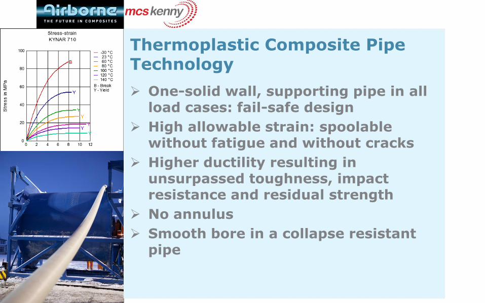
Thermoplastic Composite Pipe Technology
One-solid wall, supporting pipe in all load cases: fail-safe design
High allowable strain: spoolablewithout fatigue and without cracks
Higher ductility resulting in unsurpassed toughness, impact resistance and residual strength
No annulus
Smooth bore in a collapse resistantpipe
Global and Local Analysis
• Integrated approach of pipe design and dynamic riser response analysis
• TCR Design based on laminate theory:
– Visco-elastic behaviour of the material
– Failure modes for fibre, polymer and matrix
– Single and combined load cases
• Global riser design incorporating specific pipe weights and stiffnesses
• Materials selection based on proven track-records
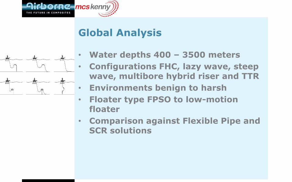
Global Analysis
• Water depths 400 – 3500 meters
• Configurations FHC, lazy wave, steep wave, multibore hybrid riser and TTR
• Environments benign to harsh
• Floater type FPSO to low-motion floater
• Comparison against Flexible Pipe and SCR solutions
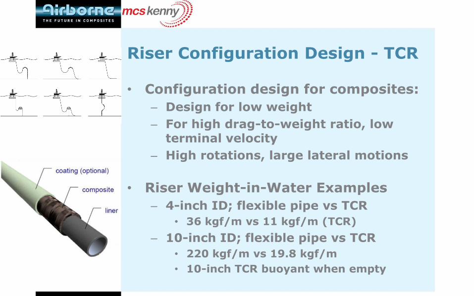
Riser Configuration Design - TCR
• Configuration design for composites:
– Design for low weight
– For high drag-to-weight ratio, low terminal velocity
– High rotations, large lateral motions
• Riser Weight-in-Water Examples
– 4-inch ID; flexible pipe vs TCR
• 36 kgf/m vs 11 kgf/m (TCR)
– 10-inch ID; flexible pipe vs TCR
• 220 kgf/m vs 19.8 kgf/m
• 10-inch TCR buoyant when empty
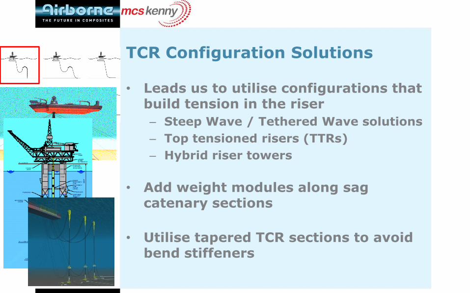
TCR Configuration Solutions
• Leads us to utilise configurations that build tension in the riser
– Steep Wave / Tethered Wave solutions
– Top tensioned risers (TTRs)
– Hybrid riser towers
• Add weight modules along sag catenary sections
• Utilise tapered TCR sections to avoid bend stiffeners

Steep Wave Riser Solution
• 2000 m WD
• GoM, WoA
and Brazil
• TCR vs
Flexible Pipe
Weight modules along
sag catenary
Results:
• 55% reduction in hang-off tension (even with weight modules added)
• 65%-75% reduction in buoyancy

Strong reduction in buoyancy
TCR: Results
Appare
nt
weig
ht
Curvilinear distance along riser
Flexible TCR-empty TCR-full
Reduced buoyancy length Weight modules
around sag bend
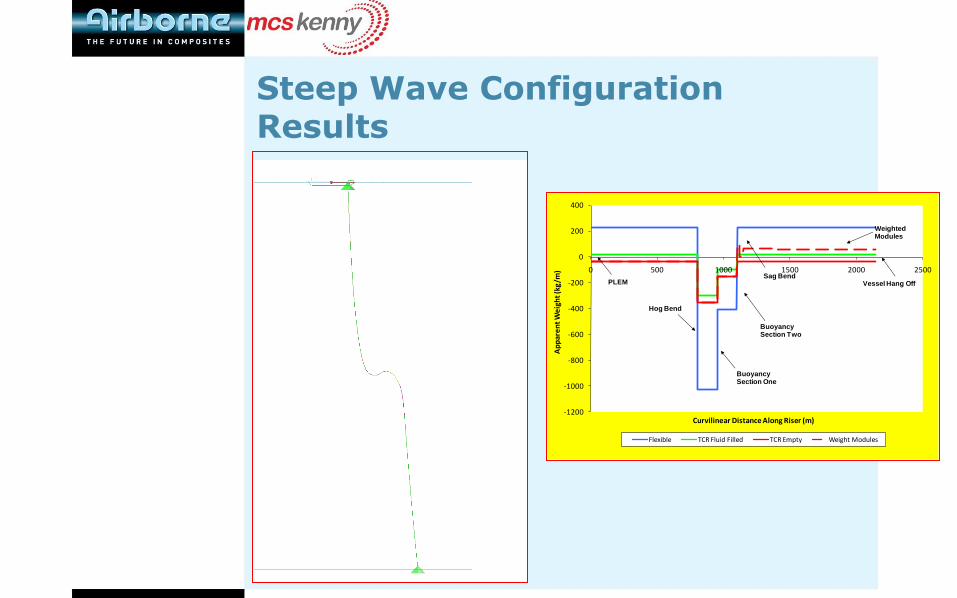
Steep Wave Configuration Results
-1200
-1000
-800
-600
-400
-200
0
200
400
0 500 1000 1500 2000 2500
Ap
par
en
t W
eig
ht
(kg
/m)
Curvilinear Distance Along Riser (m)
Flexible TCR Fluid Filled TCR Empty Weight Modules
Hog Bend
Buoyancy Section One
Weighted Modules
Buoyancy Section Two
Sag BendVessel Hang OffPLEM

Results – TTR & Hybrid Riser
• Top Tensioned Riser (2000m GoM)
– Pipe-in-pipe configuration with production tubing and outer casing
– 90% reduction in top tensions compared with steel case
– Implies much reduced top tensionerratings or smaller buoyancy cans
• Hybrid Riser in 2200m WD
– Multi-bore hybrid riser with composite production lines
– Expecting much reduced buoyancy can requirements
Global Analysis – Summary Conclusions
Solutions found to 3500+ meter water depth
Top tension reduction (>60%)
Dynamic stability critical: focus on tensioned solutions / reducing compression
Strong reduction in buoyancy requirements
Depending on size, environment and configuration limited additional weight required
Global Analysis – Summary Conclusions
Choice of PA/PVDF and Glass Fibrecreates optimal weight to strength ratio
Drag to apparent weight ratio ranges from 5-16, depending on size and materials used
Optimum found in bending stiffness, weight and Minimum Bending Radius
Global system design essential for optimal solution

Technology Acceptance (I)
• Create technology pull: JIP “Cost-Effective Thermoplastic Composite Riser”
• Sponsored by BP, Statoil, Chevron, Shell, Total, Petrobras, BG Group and SBM Offshore
• Consortium with MCS Kenny and OTM Consulting, initiated through ITF -Aberdeen
• Aim: to prove the feasibility of the TCR in dynamic riser applications

Technology Acceptance (II)
• Qualification strategy
– DNV RP A203 Qualification Procedures for New Technologies
– DNV OS C501 composite components
– DNV OS F201 dynamic riser
– DNV RP F202 recommended practice for composite riser
• Full qualification product approval
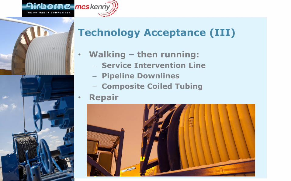
Technology Acceptance (III)
• Walking – then running:
– Service Intervention Line
– Pipeline Downlines
– Composite Coiled Tubing
• Repair
Conclusions
• 60% top tension reduction with dynamically stable system achievable with Thermoplastic Composite Riser system
• Reduced requirement for buoyancy
• Solutions found to 3500+ meters water depth
• Dynamic stability as critical issue addressed through integrated approach of local and global design

Repair
• Procedure for field repair
• Same strength as before damage

Connectors and End-fittings
• Proven clamping mechanism
• No termination of individual layers
• Bend strain relief
• MCI fits on ANSI, API, Grayloc etc
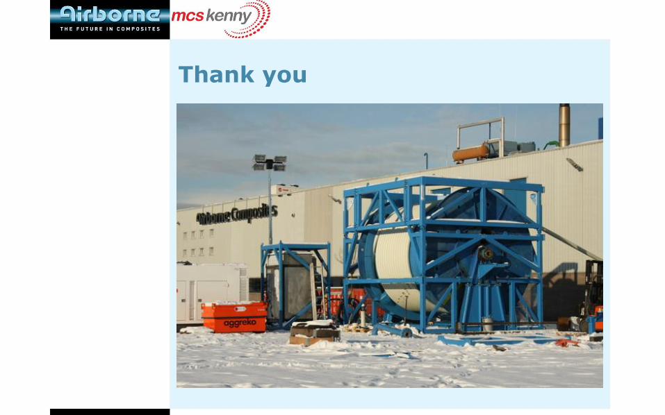
Thank you


![[SnTF] NEET Onna to Shougaku 2-Nensei 01](https://static.fdocuments.net/doc/165x107/577ccfa11a28ab9e7890364a/sntf-neet-onna-to-shougaku-2-nensei-01.jpg)


![[SnTF] NEET Onna to Shougaku 2-Nensei 02](https://static.fdocuments.net/doc/165x107/577ccfb21a28ab9e78905626/sntf-neet-onna-to-shougaku-2-nensei-02.jpg)