A new potentiometer for the measurement of electromotive ...
15
A NEW POTENTIOMETER FOR THE MEASUREMENT OF ELECTROMOTIVE FORCE AND CURRENT. By H. B. Brooks. 1. INTRODUCTION. Instruments for the measurement of electromotive force and cur- rent may be divided into two main classes. In those of the first class, which may be called deflection instruments, a movement of one element of the instrument is produced against an opposing force, an indication of the quantity to be measured being given by the extent of the motion, as shown by an index moving over a graduated scale. To this class belong many types of ammeters and voltmeters, such as the moving coil, the magnetic vane, electro- dynamometer, hot wire, and electrostatic instruments. Those of the second class may be called balance instruments. In these the electric quantity to be measured exerts a force which is opposed by another force, an adjustment of the instrument being made until no motion results, when the quantity to be measured is determined by the extent of the necessary adjustment. To this class belong Wheatstone bridges, potentiometers, and Kelvin balances. Each of these two classes of measuring instruments has its advan- tages and disadvantages. The deflection instrument can not be read, as a rule, with an accuracy greater than one part in a thousand; while on account of zero errors, inaccuracy of the scale, heating due to the current, changes of external temperature, stray magnetic fields, and other disturbing influences, the accuracy really obtained in the result is much lower than this. It is possible, of course, to determine and allow for some of these errors, but others, such as those due to stray field, are not easily allowed for. The balance instrument can usually be read with greater accuracy, and in the 225
Transcript of A new potentiometer for the measurement of electromotive ...
A NEW POTENTIOMETER FOR THE MEASUREMENT OFELECTROMOTIVE FORCE AND CURRENT.
By H. B. Brooks.
1. INTRODUCTION.
Instruments for the measurement of electromotive force and cur-
rent may be divided into two main classes. In those of the first
class, which may be called deflection instruments, a movement of
one element of the instrument is produced against an opposing
force, an indication of the quantity to be measured being given
by the extent of the motion, as shown by an index moving over a
graduated scale. To this class belong many types of ammeters and
voltmeters, such as the moving coil, the magnetic vane, electro-
dynamometer, hot wire, and electrostatic instruments. Those of
the second class may be called balance instruments. In these the
electric quantity to be measured exerts a force which is opposed by
another force, an adjustment of the instrument being made until
no motion results, when the quantity to be measured is determined
by the extent of the necessary adjustment. To this class belong
Wheatstone bridges, potentiometers, and Kelvin balances.
Each of these two classes of measuring instruments has its advan-
tages and disadvantages. The deflection instrument can not be read,
as a rule, with an accuracy greater than one part in a thousand;
while on account of zero errors, inaccuracy of the scale, heating due
to the current, changes of external temperature, stray magnetic
fields, and other disturbing influences, the accuracy really obtained
in the result is much lower than this. It is possible, of course, to
determine and allow for some of these errors, but others, such as
those due to stray field, are not easily allowed for. The balance
instrument can usually be read with greater accuracy, and in the
225

226 Bulletin ofthe Bureaii ofStandards. [Vol. 2, jvo. 2.
case of the potentiometer the accuracy of reading may be carried to
almost any desired extent by using a sufficiently sensitive galvano-
meter.
Instruments of the deflection type are, as a rule, more liable to
change their constants with time than those of the balance type.
This is especially true of the moving coil instrument, where mag-
net and spring are subject to changes which affect the readings.
Besides a gradual change in the strength of the magnet as time goes
on, and sudden changes due to blows, a temporary change in the
strength of the magnetic field in which the coil moves may be pro-
duced by heavy currents in conductors near which the instrument
may be used or by the stray field from other instruments. Balance
instruments, on the other hand, usually retain their calibration very
well, and are not affected, either temporarily or permanently, by
disturbing influences which seriously affect the other class.
Deflection instruments are especially useful in commercial work
where great accuracy is not required. They have the advantages
of requiring no special setting up, of being quickly read, and of
always indicating, approximately at least, the value of the quantity
to be measured. Balance instruments are particularly useful in
laboratory work where accuracy is essential, and where steady elec-
trical conditions can be maintained. Their use requires much time,
as every change in the quantity under measurement requires an
adjustment to be made for the condition of no deflection. In the
determination of unknown masses, first by a spring balance and
second by the equal arm balance, using standard masses, we have
conditions similar to those attending the use of the two classes of
electrical measuring instruments.
2. THE POTENTIOMETER METHOD.
For precision measurements of direct current and electromotive
force, in terms of standards of electromotive force and of resistance,
the potentiometer method excels in accuracy, flexibility, and range of
application, and it is to-day the standard method for such measure-
ments. The potentiometer is unaffected by external disturbances, if
we except the effect of leakage currents, which should be guarded
against. Its accuracy is dependent upon the accuracy of adjustment
of resistance coils, and its permanency of calibration depends upon the
Brooks.] A New Potentiometer. 227
constancy of the relative values of these coils, and the constancy of
the standard cell used. Resistances may be adjusted and compared
with an accuracy much greater than that obtained in other electrical
measurements, and the errors in the coils may be determined and
allowed for at any time in accurate work. Standard cells, while not
in a perfectly satisfactory condition at present, are readily compared
with each other with great accuracy, and when properly made are
very reliable.
On the other hand, the disadvantages of the potentiometer method
are the time required to make the measurements, the bulk and cost
of the apparatus, and the fact that the current or voltage must be
kept steady while being measured, it being practically impossible to
use a potentiometer on a circuit where the current or voltage is sub-
ject to fluctuations of any magnitude. Attempts have been made
from time to time to introduce potentiometers for use as standard
instruments in central station and similar work. An interesting
example is the Howell voltmeter, used in early Edison stations.
This was a portable potentiometer in compact form, comprising gal-
vanometer, standard cell and resistance coils, one of these coils hav-
ing a sliding contact, the position of which, when the galvanometer
showed no deflection, was an indication of the pressure at the instru-
ment terminals. One form of this instrument was small enough to
be carried in a coat pocket. Special Daniell cells were used at first,
and later a form of Clark cell, a thermometer being necessary with
the latter.
Attempts have been made from time to time to introduce in prac-
tice more elaborate forms of portable potentiometer as standard
instruments for use in checking deflection instruments ; but these
attempts have not met with entire success. The need unquestion-
ably exists for a type of instrument for current and voltage measure-
ments which will have properties intermediate between those of
the ordinary deflection instrument and the elaborate potentiometer.
For example, in reading ordinary portable ammeters and volt-
meters the limit of accuracy of reading, for, say, two-thirds of full
scale deflection, is about one part in a thousand. For checking
these a standard instrument which can be easily read to this degree
of accuracy and estimated five times further is amply sensitive.
To meet this need there has been offered a larger form of deflec-
228 Bulletin of the Bureau ofStandards. [Voi. 2,No.2.
tion instrument for current and voltage measurements, to which
the name "laboratory standard" has been applied. While the
larger dimensions allow the heat generated to be thrown off
with a smaller rise of temperature, and the longer pointer allows a
somewhat more accurate reading of the deflection to be made, these
instruments are not entirely satisfactory for the purpose for which
they were produced, and for careful work need to be checked by a
potentiometer at rather frequent intervals, under the conditions of
use. These instruments are affected by stray field and other dis-
turbing influences in the same way as the smaller instruments,
though not to as great an extent.
The standard instrument should however be practically free from
the sources of error which affect the deflection instrument, and
should be so constructed that its constants will not be liable to alter
with time. It should be possible to use it even on circuits that are
not steady, and it should require as little manipulation as possible.
It should be compact, simple, and not too expensive, and it should
be made so as to be readily checked. In other words, it should
combine as much as possible of the convenience of the deflection
instrument and the accuracy and constancy of the potentiometer.
Such an instrument would be useful in the central station, for the
checking of portable and of switchboard instruments, some forms of
which latter should be tested in position under the conditions of use.
It would be of service in the instrument factory, where a large num-
ber of instruments must be tested, and in the laboratory, for meas-
urements in which a greater degiee of accuracy is required than can
be had using deflection instruments. It would be of service in
photometry, where a degree of accuracy in voltage measurements is
needed which is obtained with deflection instruments only by great
care in reading and by constantly falling back upon the potentiom-
eter as a check on the relatively large changes, due to heating and
other causes, which occur in the best deflection instruments. Other
uses might be mentioned, but it is evident from the above that a
field exists for an intermediate type of instrument.
3 THE DEFLECTION POTENTIOMETER.
With the above requirements in mind, it occurred to me that a
satisfactory instrument for this work might be realized by using
the potentiometer method to measure the bulk of the electrical

Brooks.] A New Potentiometer. 229
quantity, in conjunction with a suitable deflection instrument to
measure the small remainder, which may be of the order of 1 per
cent of the total.1 For example, if an electromotive force is between
no and in volts, the potentiometer method may be used to
measure the no, the decimal part being read by deflection. Thepotentiometer is essentially a null instrument, and the function of
the galvanometer ordinarily is to show, by the absence of a deflec-
tion, when the unknown electromotive force is compensated by the
known. In some cases, however, as in measuring low electromotive
forces, we desire to read one more figure in addition to that given
by the lowest dial ; and in such a case, with some forms of poten-
tiometer, we may interpolate between adjacent settings on this dial,
just as we interpolate in Wheatstone bridge and other resistance
work. In doing this we assume that within this narrow range the
deflection is proportional simply to the unbalanced portion of the
electromotive force. In the present case the problem is to deter-
mine the conditions to be met, first, in order that the deflection
corresponding to a given unbalanced electromotive force may always
be the same, regardless of the setting of the potentiometer dials
;
and, secondly, in order that the deflection should be strictly pro-
portional to the unbalanced electromotive force for a relatively
large unbalancing, as it is ordinarily assumed to be for a small
unbalancing.
To reduce the necessary manipulation to a minimum, there should
be but one dial to be set, one step of which covers from 1 to perhaps 5
per cent of the total range. In the latter case, to secure an accuracy
of one-twentieth of 1 per cent, the deflection instrument must meas-
ure the unbalanced 5 per cent with an accuracy of 1 per cent. If the
steps on the main dial are not so large, the accuracy required in the
galvanometer is not so great.
x The idea of balancing the larger portion of an unknown emf. by the potentiom-
eter method, the remainder being indicated by the deflection of a galvanometer,
was suggested by Stansfield and used by him in the construction of a recording
pyrometer. (Phil. Mag. 5, 46, p. 59, 1898.) In his apparatus a Clark cell of large
size was used to furnish the working current through the potentiometer wire, and it
was necessary to have a second potentiometer to determine the value of this current.
More recently the same idea has been used for pyrometric work by Hoffmann andRothe. (Zs. fur Instrumentenkunde, Sept., 1905.) In their apparatus also the
indication of the galvanometer does not give at once the value of the unknown emf.,
auxiliary observations and calculations being required.
230 Bulletin ofthe Bureau ofStandards. \Voi.2,No.2.
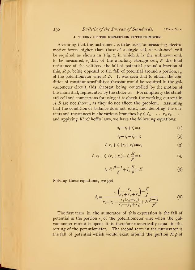
4. THEORY OF THE DEFLECTION POTENTIOMETER.
Assuming that the instrument is to be used for measuring electro-
motive forces higher than those of a single cell, a u volt-box" will
be required, as shown in Fig. 1, in which E is the unknown emf.
to be measured, exthat of the auxiliary storage cell, R the total
resistance of the volt-box, the fall of potential around a fraction of
this, Rip, being opposed to the fall of potential around a portion, r15
of the potentiometer wire A B. It was seen that to obtain the con-
dition of constant sensibility a rheostat would be required in the gal-
vanometer circuit, this rheostat being controlled by the motion of
the main dial, represented by the slider S. For simplicity the stand-
ard cell and connections for using it to check the working current in
A B are not shown, as they do not affect the problem. Assuming
that the condition of balance does not exist, and denoting the cur-
rents and resistances in the various branches by tL1t„ . . . rn r
2 ,. . .
and applying KirchhorPs laws, we have the following equations:
h-h-ig.= o (2)
h rx+ h (r.
z+ rz)= e
x (3)
h n~h (r
>+ re)- z\ -p=° (4)
i.R£=±+i£=E. (5)P P
Solving these equations, we get
A a )EP
(6)
The first term in the numerator of this expression is the fall of
potential in the portion rxof the potentiometer wire when the gal-
vanometer circuit is open ; it is therefore numerically equal to the
setting of the potentiometer. The second term in the numerator is
the fall of potential which would exist around the portion Rip of

Brooks.] A New Potentiometer. 231
the volt-box if the galvanometer circuit were open. The denomina-
tor is the total resistance in the galvanometer circuit, the third term
being the resultant resistance of the portion rxof the potentiometer
wire shunted by the remainder of the battery circuit, and the fourth
term is the resistance of the portion Rjp in parallel with the remain-
p-ider of the volt-box, R^
pEquation (6) therefore shows that the
current through the galvanometer is equal to the unbalanced portion
of the electromotive force divided by the total resistance of the gal-
vanometer circuit ; or
-VWVWV\M^^p-i
A/VVV\/VW\A^^
^AV/AAAAAA/WWVWWWVvWV\MM/WvVi-b
VVvVvWv\AAAAAAVvV\
Fig. 1.
—
First Plan of Circuits.
Referring to equation (6), we may denote the first term in the
numerator, which may be called the setting, by s. Since the volt-
box has a multiplying power of p, the equation may be written in
the form
>.-PJ m
which shows that if 2r can be kept constant the galvanometer cur-
rent will be directly proportional to (ps—E), the difference between
232 Bulletin ofthe Bureau ofStandards. \_v i.2,no.2.
the emf. corresponding to the setting and the emf. to be measured.
If 2r can be kept constant for all settings, it is only necessary to
calibrate the scale of the galvanometer properly to make it read
directly the unbalanced part of the emf. under measurement. Refer-
ring to Fig. 1 and equation (6), it will be seen that the resistance r4
must have such values for different positions of the slider S that the
r (r -\- r ^
sum of r. and—^—-^ will be a constant. The latter has a maxi-^i+OVr-^)
mum value at some point between A and B, and minimum values
at A and B ; so that r4must vary accordingly.
A difficulty in the way of using this particular arrangement of
circuits lies in the fact that the value of exdepends on the condition
of the storage cell, and as exvaries r
3must be varied to keep the
proper current through A B. This double variation of the setting
and of r3is difficult to compensate for accurately, since for settings
near A changes of r3make very little change in the resultant resist-
ance, while for settings near B the changes of r3enter almost undi-
minished into the resistance of the galvanometer circuit. We mayuse a number of cells in place of one, giving a larger current through
A B, and thus limiting the part of A B used to a relatively small
portion near A. This would give a sufficiently accurate compensa-
tion for most purposes; but another arrangement of circuits may be
used which does not have the objection of requiring a number of
cells, one being sufficient, while the compensation for changes in the
setting and in the battery rheostat may be made as perfect as desired.
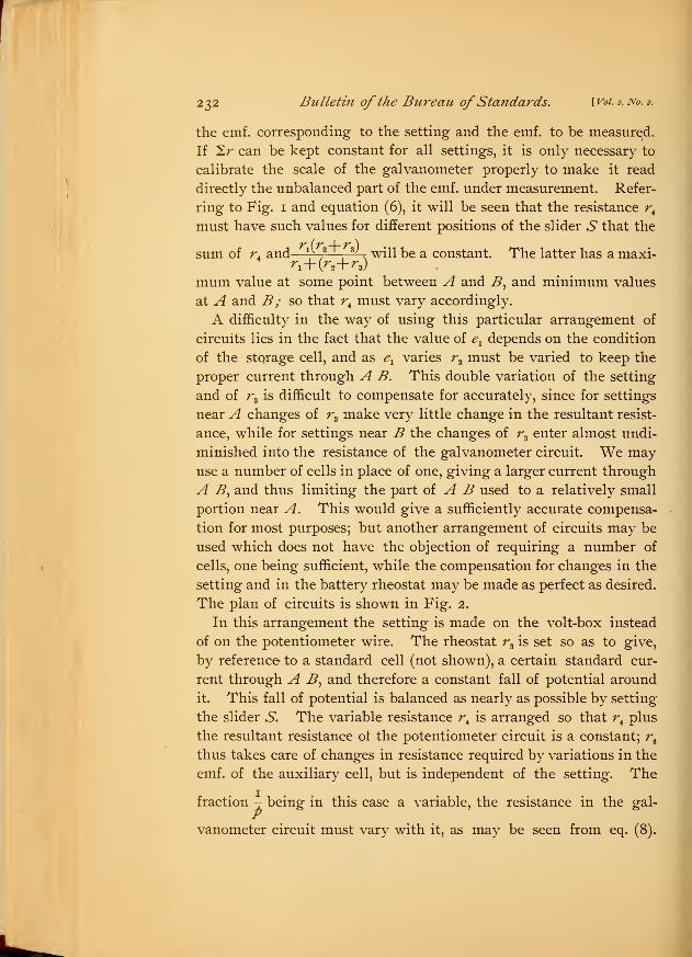
The plan of circuits is shown in Fig. 2.
In this arrangement the setting is made on the volt-box instead
of on the potentiometer wire. The rheostat r3is set so as to give,
by reference to a standard cell (not shown), a certain standard cur-
rent through A B, and therefore a constant fall of potential around
it. This fall of potential is balanced as nearly as possible by setting
the slider S. The variable resistance r4is arranged so that r
4plus
the resultant resistance ol the potentiometer circuit is a constant; r4
thus takes care of changes in resistance required by variations in the
emf. of the auxiliary cell, but is independent of the setting. The
fraction - being in this case a variable, the resistance in the gal-
vanometer circuit must vary with it, as may be seen from eq. (8).
Brooks.] A New Potentiometer. 233
Since in this second arrangement the emf. term e1
stant, we may denote it by e. We have then
1 pe—E
n+ ^3is a con-
(9)
For a difference of one volt between the setting^ and the emf. Eunder measurement the galvanometer is to give a deflection of m
II-- II
-T>
-AWvVvYvY^YAM^^
AVWVWVVVYMH
rV\AMWvVv\w\/
Fig. 2.—Second Plan of Circuits.
scale divisions. If / denote the current required to give a deflection
of one scale division, the current ml must always flow whenpe—E— 1. Substituting these values, we have
mI=\-Tr (10)
2r: pm I («)
Eq. (10) shows that the compensating resistance r5in the galvanom-
eter circuit, which is controlled by the movement of the slider S,
must vary so as to keep the product/ 2r a constant. Eq. (11) holds
234 Bulletin ofthe Bureau ofStandards. [voi.2,Ao. 2 .
for the first arrangement also, shown in Fig. :
a constant, Sr must be constant and equal to
for the first arrangement also, shown in Fig. i ; in this case, p being
i
pmlThe galvanometer to be used as a part of this instrument should
be of the needle type, preferably one that is pivoted and does not
require an arrestment. It should have a good zero, a short period,
and a calibrated scale. For laboratory use a reflecting galvanom-
eter of short period may be used, but in many applications, as in
checking switchboard instruments in position, the use of such a
galvanometer would be a serious drawback, and since the high
sensibility of the reflecting galvanometer is not required for the
middle class of measurements for which this type of potentiometer
is designed, it would seem better to use, in most cases, the more
compact and easily manipulated needle instrument, which makes
the apparatus portable and always ready for use. The galvanom-
eter should have, for use in voltage measurements, a sensibility of a
millimeter deflection for from two to four microamperes, unless a
very high resistance is required in the volt-box circuit. The cali-
bration of the scale should be carefully tested, as there are portable gal-
vanometers which have fair working qualities and high average sensi-
bility, but which have a sensibility at some parts of the scale nearly
double that at others. The satisfactory working of the apparatus
will depend considerably upon the working qualities of the galvanom-
eter, and hence care should be used in selecting this instrument.
A point to be considered is the value of the total resistance at which
the galvanometer is aperiodic. For good results the resistance in
the galvanometer circuit should be equal to or slightly greater than
this resistance. In the first arrangement of circuits (Fig. i) in
which the total resistance of the galvanometer circuit is a constant,
the damping may be external to any desired extent; but for the
second case, with a large variation in the resistance of the galvanom-
eter circuit, this resistance should be relatively high and the damp-
ing largely internal.
5. CONSTRUCTION OF THE INSTRUMENT.
A deflection potentiometer has recently been constructed in the
instrument shop of this Bureau from my designs in accordance with
the foregoing principles, and has been put into service for voltage
measurements in the photometric work of the Bureau.
Brooks.-] A New Potentiometer. 235
In this work a standard potentiometer has been used for the most
accurate measurements, and it will continue to be used. The less
accurate measurements had previously been made with regular port-
able instruments, but it was found impossible to secure the desired
accuracy in this way. Portable instruments must be frequently
calibrated, and must be connected to the circuit at the proper volt-
age for some time before use, in order to warm up and reach a steady
condition. The estimation of tenths of a division requires close
inspection and a relatively large amount of time, while the personal
equation enters into the result. The measurement of voltage as
previously carried out set a limit of accuracy to the photometric
measurements somewhat lower than was desired. A potentiometer
of standard form would give even greater accuracy than is required,
but its use would consume too much time. The deflection poten-
tiometer gives ample accuracy, the estimation of tenths of a division
being unnecessary, and in using it for a lot of lamps of approxi-
mately equal voltage accurate readings can be taken more rapidly
than with a voltmeter. If every lamp has a different voltage, the
necessary adjustment of the dial would reduce the speed, but even
in this case the consideration of accuracy in the work of the Bureau
is given greater weight than the speed of working.
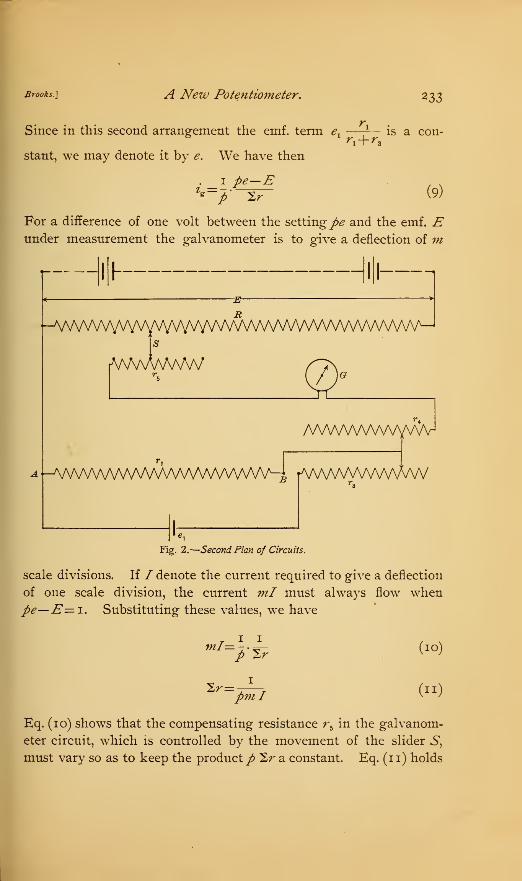
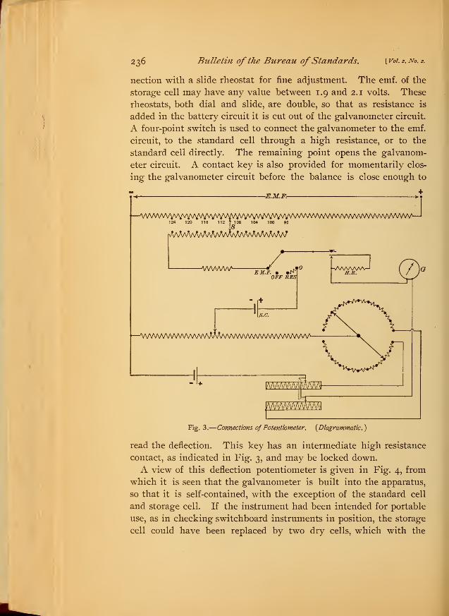
The range of this instrument is from 95 to 125 volts. Fig. 3 gives
a diagrammatic plan of the circuits in the instrument. The main
dial has 15 steps, each of 2 volts, the galvanometer normally cover-
ing a range of 2 volts, although it may be used over a range of 3
volts; that is, 1.5 volts on each side of the setting. To avoid
errors in the photometric work the resistance R was made high,
being 50,000 ohms. The resistance in the battery circuit is 2,000
ohms total when the emf. of the storage cell is 2 volts. On account
of these high resistances the galvanometer sensibility required is
greater than would ordinarily be necessary. The galvanometer was
supplied by the Weston Electrical Instrument Company and is their
regular model A, of higher sensibility than usual, giving 1 mmdeflection for 1.6 microamperes. The internal resistance is 270
ohms and the period on open circuit 1.3 seconds. When in use,
with its circuit closed through the potentiometer, the motion of the
needle is very nearly aperiodic and readings may be quickly made.
The battery current is regulated by a rheostat of 10 steps in con-
236 Bulletin of the Bureau ofStandards. [ Vol. 2, No. 2.
nection with a slide rheostat for fine adjustment. The emf. of the
storage cell may have any value between 1.9 and 2.1 volts. These
rheostats, both dial and slide, are double, so that as resistance is
added in the battery circuit it is cut out of the galvanometer circuit.
A four-point switch is used to connect the galvanometer to the emf.
circuit, to the standard cell through a high resistance, or to the
standard cell directly. The remaining point opens the galvanom-
eter circuit. A contact key is also provided for momentarily clos-
ing the galvanometer circuit before the balance is close enough to
—VVWWVVVYWWVVVVWN'W^—
1
124 120 116 112 t 108 104 100 96
rMA^VvV^AMMAA^MAAAAAAMAA7
~KM.Fr-
JWWWVLEM.F. • •J^T
OFF RES
s.c.
--^vwwwvwwvwMvVvv^^
Fig. 3.
—
Connections of Potentiometer. {Diagrammatic.)
read the deflection. This key has an intermediate high resistance
contact, as indicated in Fig. 3, and may be locked down.
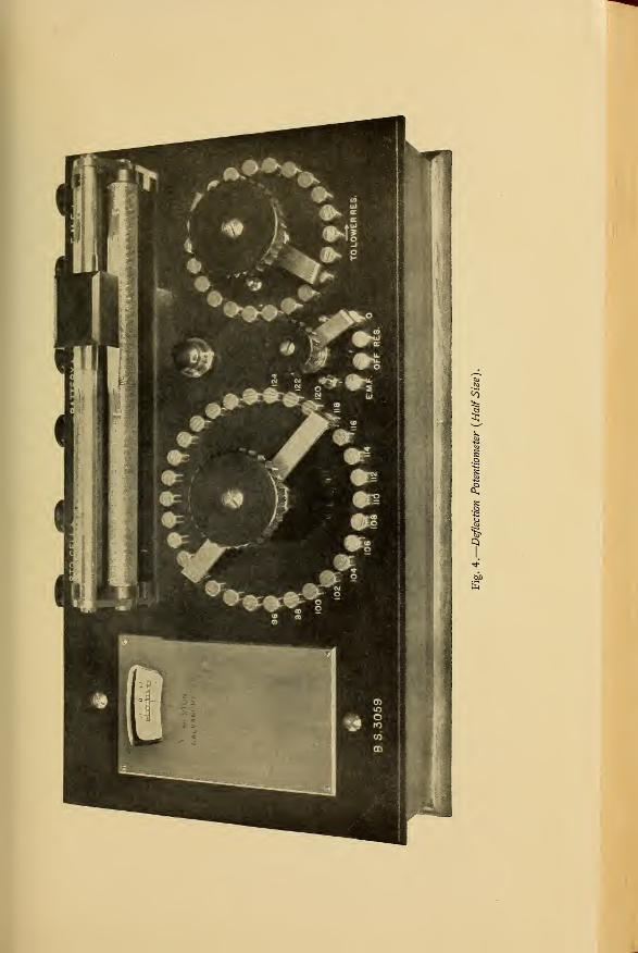
A view of this deflection potentiometer is given, in Fig. 4, from
which it is seen that the galvanometer is built into the apparatus,
so that it is self-contained, with the exception of the standard cell
and storage cell. If the instrument had been intended for portable
use, as in checking switchboard instruments in position, the storage
cell could have been replaced by two dry cells, which with the
to
Brooks.] A New Potentiometer. 237
standard cell could have been inclosed in the case, making the
entire apparatus se"!f-contained. Special precaution was taken to
guard against leakage from the volt-box coils to the low-voltage
circuits and the galvanometer, the guard-ring principle being used.
The dimensions of the instrument are as follows : Length, 33 cm
;
breadth, 19 cm;
height, 13.6 cm. The weight without cells is
4.75 kilograms.
A test showed that over the whole range the greatest error was
0.02 volt, the error when no deflection occurs, as at 96, 98, etc., not
exceeding 0.01 volt at any point.
The design of a larger instrument of this type is under considera-
tion. This will be used for checking voltmeters, and the dial will
consequently have a greater number of points than in the instru-
ment just described. By means of a switch the standard cell maybe balanced around different portions of the potentiometer wire,
giving working currents through the wire in proportion to the num-
bers 1, 2, 4, or whatever values may be desired. By making the
volt-box so that the highest voltage to be measured will not produce
undesirable heating, the same instrument may be used for various
ranges, as 150, 300, and 600 volts. The details of this second
instrument are not sufficiently developed at this time to give a
description of it.
6. APPLICATION TO CURRENT MEASUREMENT.
It is interesting to note that while the plan of circuits shown in
Fig. 1 is not convenient for use in measuring voltages higher than
those of a single cell, it is the most suitable one to use in a deflec-
^tion potentiometer for measuring currents. Here the fall of poten-
tial at the terminals of a current shunt is to be measured, and this
fall of potential being small, it is desirable to use all of it. Further,
if we were to use the plan shown in Fig. 2 for this work it would
be necessary to construct a special shunt for each range, with a
large number of potential points accurately located. With the plan
shown in Fig. 1 any standard current shunt may be used, and it need
not be an integral part of the potentiometer proper, which thus con-
stitutes a precision millivoltmeter.
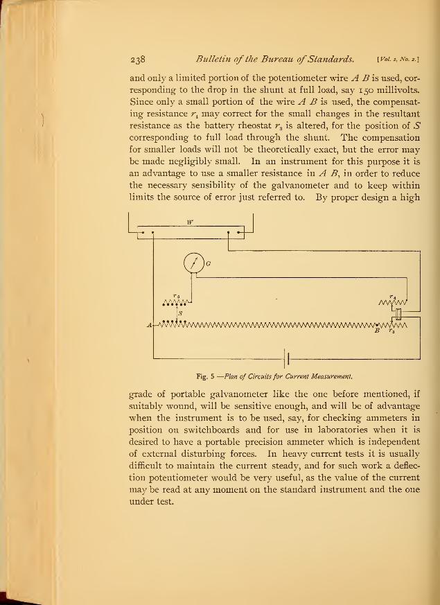
The circuits for an instrument of this kind are shown in Fig. 5.—
238 Bulletin of the Bureau ofStandards. [Vol. 2, No. 2.]
and only a limited portion of the potentiometer wire A B is used, cor-
responding to the drop in the shunt at full load, say 150 millivolts.
Since only a small portion of the wire A B is used, the compensat-
ing resistance rkmay correct for the small changes in the resultant
resistance as the battery rheostat r3is altered, for the position of .S
corresponding to full load through the shunt. The compensation
for smaller loads will not be theoretically exact, but the error maybe made negligibly small. In an instrument for this purpose it is
an advantage to use a smaller resistance in A B)in order to reduce
the necessary sensibility of the galvanometer and to keep within
limits the source of error just referred to. By proper design a high
w
MWaL^W
/VWVVV
Fig. 5 —Plan of Circuits for Current Measurement.
grade of portable galvanometer like the one before mentioned, if
suitably wound, will be sensitive enough, and will be of advantage
when the instrument is to be used, say, for checking ammeters in
position on switchboards and for use in laboratories when it is
desired to have a portable precision ammeter which is independent
of external disturbing forces. In heavy current tests it is usually
difficult to maintain the current steady, and for such work a deflec-
tion potentiometer would be very useful, as the value of the current
may be read at any moment on the standard instrument and the one
under test.


![Improvement of position measurement for 6R robot using ...jcarme.sru.ac.ir/article_517_d68c09935729e58ee4467bef70b1072e.pdf · speed [5]. Moreover, a potentiometer was used to measure](https://static.fdocuments.net/doc/165x107/5e7f445ff82c317aa07b2c38/improvement-of-position-measurement-for-6r-robot-using-speed-5-moreover.jpg)