A New Moving-magnet Type Linear Actuator utilizing … New Moving-magnet Type Linear Actuator ......
7
Journal of Electrical Engineering & Technology Vol. 7, No. 3, pp. 342~348, 2012 http://dx.doi.org/10.5370/JEET.2012.7.3.342 342 A New Moving-magnet Type Linear Actuator utilizing Flux Concentration Permanent Magnet Arrangement Akira Goto*, Takuya Okamoto*, Atsushi Ikariga** , ***, Takashi Todaka † and Masato Enokizono** Abstract – This paper presents a moving-magnet type linear actuator designed by using flux concentration type permanent magnet arrangement, which can generate higher magnetic flux density in air-gap. In this construction, detent force which is induced by both slot-effect and end-effect becomes larger due to strong attractive forces. To reduce cogging force we have employed a modular mover structure of two magnetic pole sections connected with a center yoke. The improved motor performance is demonstrated with the prototype machine. Keywords: Linear motor, Moving magnet type, Cogging, Thrust, Center yoke, End yoke 1. Introduction Linear drive actuators have many advantages in comparison with ball screws and have widely used in many applications [1, 2]. Also considerable attentions have been paid to development of high-speed and high-precision linear motion control system due to the increasing demand for higher productivity and better product quality in the advanced manufacturing industries such as industrial process machinery. In this paper, a new moving magnet type linear actuator utilizing flux concentration type permanent magnet arrangement is proposed [3, 4]. The flux concentration type means that the same magnetic poles are faced each other and then higher magnetic flux density over the remanence obtains. In this construction, detent force induced by both slot-effect and end-effect deteriorates the motor performance. Some effective methods to reduce detent force have been suggested so far [5-7]. We employed a modular mover structure connected with a center yoke. The mover consists of two sections and it is possible to change distance between one section and the other section for any electrical degree. The width of the center yoke and the end yoke were optimized to reduce cogging force and improve thrust force by using the finite element method. The designed performance is verified in comparison of measured results with the calculated ones. 2. Analyzed Model and Cogging Reduction 2.1 Analyzed model and conditions Fig. 1 shows the construction of the mover. As shown in this figure, the two mover sections are jointed with the center yoke whose width is T [mm]. The each magnetic pole consists of three permanent magnets faced to each other to generate higher magnetic field in air gap. The arrows indicate the direction of the magnetization. The upper permanent magnets near the back yoke give main flux and the lower permanent magnets magnetized horizontally adjust flux distribution desired in air gap. Fig. 1. Overview of the new linear actuator (a) Common (b) Concentrated Fig. 2. Magnetic flux distribution near the common SPM and the new mover surface † Corresponding Author: Department of Electrical and Electronic Engineering, Faculty of Engineering, Oita University, Japan (todaka @oita-u.ac.jp) * Ishii Tool & Engineering Corporation, Oita, Japan ([email protected]) ** Department of Electrical and Electronic Engineering, Faculty of Engineering, Oita University, Japan *** Oita Prefectural Organization for Industry Creation, Oita, Japan ([email protected]) Received: December 28, 2010; Accepted: December 3, 2011
Transcript of A New Moving-magnet Type Linear Actuator utilizing … New Moving-magnet Type Linear Actuator ......
Journal of Electrical Engineering & Technology Vol. 7, No. 3, pp. 342~348, 2012 http://dx.doi.org/10.5370/JEET.2012.7.3.342
342
A New Moving-magnet Type Linear Actuator utilizing Flux Concentration Permanent Magnet Arrangement
Akira Goto*, Takuya Okamoto*, Atsushi Ikariga**,***, Takashi Todaka† and Masato Enokizono**
Abstract – This paper presents a moving-magnet type linear actuator designed by using flux concentration type permanent magnet arrangement, which can generate higher magnetic flux density in air-gap. In this construction, detent force which is induced by both slot-effect and end-effect becomes larger due to strong attractive forces. To reduce cogging force we have employed a modular mover structure of two magnetic pole sections connected with a center yoke. The improved motor performance is demonstrated with the prototype machine.
Keywords: Linear motor, Moving magnet type, Cogging, Thrust, Center yoke, End yoke
1. Introduction
Linear drive actuators have many advantages in comparison with ball screws and have widely used in many applications [1, 2]. Also considerable attentions have been paid to development of high-speed and high-precision linear motion control system due to the increasing demand for higher productivity and better product quality in the advanced manufacturing industries such as industrial process machinery.
In this paper, a new moving magnet type linear actuator utilizing flux concentration type permanent magnet arrangement is proposed [3, 4]. The flux concentration type means that the same magnetic poles are faced each other and then higher magnetic flux density over the remanence obtains. In this construction, detent force induced by both slot-effect and end-effect deteriorates the motor performance. Some effective methods to reduce detent force have been suggested so far [5-7]. We employed a modular mover structure connected with a center yoke. The mover consists of two sections and it is possible to change distance between one section and the other section for any electrical degree. The width of the center yoke and the end yoke were optimized to reduce cogging force and improve thrust force by using the finite element method. The designed performance is verified in comparison of measured results with the calculated ones.
2. Analyzed Model and Cogging Reduction
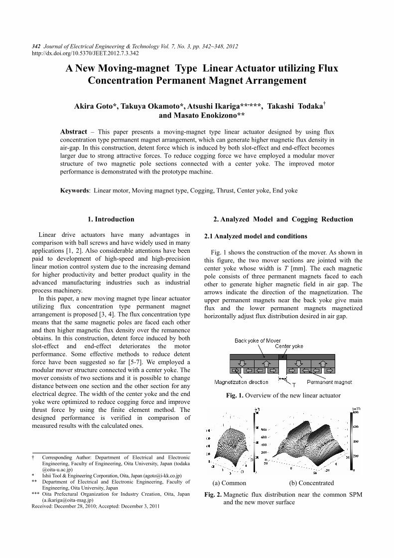
2.1 Analyzed model and conditions Fig. 1 shows the construction of the mover. As shown in
this figure, the two mover sections are jointed with the center yoke whose width is T [mm]. The each magnetic pole consists of three permanent magnets faced to each other to generate higher magnetic field in air gap. The arrows indicate the direction of the magnetization. The upper permanent magnets near the back yoke give main flux and the lower permanent magnets magnetized horizontally adjust flux distribution desired in air gap.
Fig. 1. Overview of the new linear actuator
(a) Common (b) Concentrated
Fig. 2. Magnetic flux distribution near the common SPM and the new mover surface
† Corresponding Author: Department of Electrical and Electronic Engineering, Faculty of Engineering, Oita University, Japan ([email protected])
* Ishii Tool & Engineering Corporation, Oita, Japan ([email protected]) ** Department of Electrical and Electronic Engineering, Faculty of
Engineering, Oita University, Japan *** Oita Prefectural Organization for Industry Creation, Oita, Japan
([email protected]) Received: December 28, 2010; Accepted: December 3, 2011
Akira Goto, Takuya Okamoto, Atsushi Ikariga, Takashi Todaka and Masato Enokizono
343
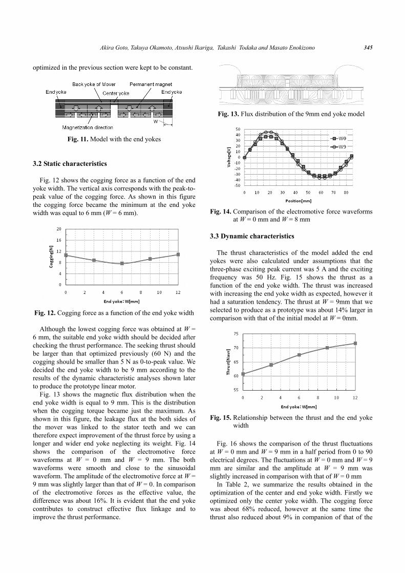
Fig. 3. Analyzed linear motor model (prototype)
Table 1. Specifications of the prototype model
Air gap length [mm] g 1.5 Number of poles p 4 Pole pitch [mm] τp 42 Slot pitch [mm] τs 28
Remanence of PM [T] Br 1.325 Number of turns [turns / slot] w 57
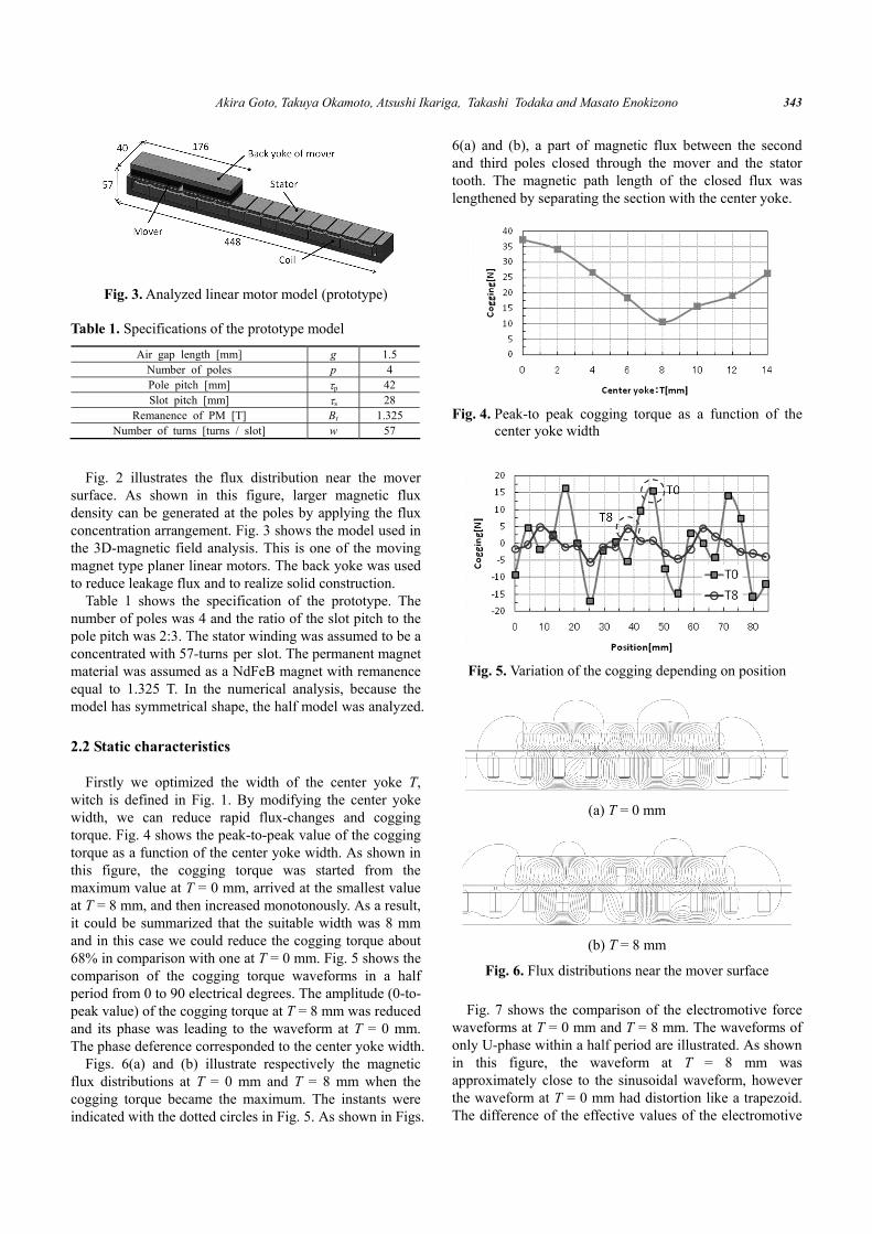
Fig. 2 illustrates the flux distribution near the mover
surface. As shown in this figure, larger magnetic flux density can be generated at the poles by applying the flux concentration arrangement. Fig. 3 shows the model used in the 3D-magnetic field analysis. This is one of the moving magnet type planer linear motors. The back yoke was used to reduce leakage flux and to realize solid construction.
Table 1 shows the specification of the prototype. The number of poles was 4 and the ratio of the slot pitch to the pole pitch was 2:3. The stator winding was assumed to be a concentrated with 57-turns per slot. The permanent magnet material was assumed as a NdFeB magnet with remanence equal to 1.325 T. In the numerical analysis, because the model has symmetrical shape, the half model was analyzed.
2.2 Static characteristics
Firstly we optimized the width of the center yoke T,
witch is defined in Fig. 1. By modifying the center yoke width, we can reduce rapid flux-changes and cogging torque. Fig. 4 shows the peak-to-peak value of the cogging torque as a function of the center yoke width. As shown in this figure, the cogging torque was started from the maximum value at T = 0 mm, arrived at the smallest value at T = 8 mm, and then increased monotonously. As a result, it could be summarized that the suitable width was 8 mm and in this case we could reduce the cogging torque about 68% in comparison with one at T = 0 mm. Fig. 5 shows the comparison of the cogging torque waveforms in a half period from 0 to 90 electrical degrees. The amplitude (0-to-peak value) of the cogging torque at T = 8 mm was reduced and its phase was leading to the waveform at T = 0 mm. The phase deference corresponded to the center yoke width.
Figs. 6(a) and (b) illustrate respectively the magnetic flux distributions at T = 0 mm and T = 8 mm when the cogging torque became the maximum. The instants were indicated with the dotted circles in Fig. 5. As shown in Figs.
6(a) and (b), a part of magnetic flux between the second and third poles closed through the mover and the stator tooth. The magnetic path length of the closed flux was lengthened by separating the section with the center yoke.
Fig. 4. Peak-to peak cogging torque as a function of the
center yoke width
Fig. 5. Variation of the cogging depending on position
(a) T = 0 mm
(b) T = 8 mm
Fig. 6. Flux distributions near the mover surface Fig. 7 shows the comparison of the electromotive force
waveforms at T = 0 mm and T = 8 mm. The waveforms of only U-phase within a half period are illustrated. As shown in this figure, the waveform at T = 8 mm was approximately close to the sinusoidal waveform, however the waveform at T = 0 mm had distortion like a trapezoid. The difference of the effective values of the electromotive

A New Moving-magnet Type Linear Actuator utilizing Flux Concentration Permanent Magnet Arrangement
344
forces at T = 0 mm and T = 8 mm was about 4% and their phase difference was similar to the cogging torque waveform mentioned in the above.
Fig. 7. Comparison of the electromotive force waveforms
at T = 0 mm and T = 8 mm Fig. 8 shows the harmonic components of the cogging
torque waveform: (a) T = 0 mm and (b) T = 8 mm. In the both cases, the 6th harmonic component became the maximum. This value agreed with the least common multiple of 2 and 3, which are ratio of the slot pitch to the pole pitch, 2:3 [8]. The 6th harmonic component at T = 8 mm became 1/3 in comparison with one at T = 0 mm.
(a) T = 0 mm
(b) T = 8 mm
Fig. 8. Harmonic components in the cogging waveforms
2.3 Dynamic characteristics The thrust characteristics were simulated under
assumptions that the three-phase exciting peak current was
5 A at 50 Hz. Fig. 9 shows the thrust as a function of the center yoke width. The thrust was the maximum at T = 0 mm and monotonously decreased with increasing the center yoke width. At T = 8 mm the thrust was about 60 N and it was decreased about 9% in comparison with the maximum at T = 0 mm. Fig. 10 shows the comparison of the thrusts at T = 0 mm and T = 8 mm, which are fluctuating depending on the electric angle. We could successively reduce the cogging torque by using the two-sectional mover structure connected with the center yoke, however a little reduction of the thrust was inevitable. Our objective of the thrust in the first stage designing was 50 N, therefore the thrust at T = 8 mm satisfied the object. As mentioned in the above, though the modular mover structure is simpler than that of skewing, it is effective to reduce cogging torque in keeping the thrust as large as possible.
Fig. 9. Thrust as a function of the center yoke width
Fig. 10. Thrust fluctuation depending on position
3. Thrust Improvement with the End Yoke
3.1 Analyzed model and conditions
In order to improve the thrust of the modular mover
structure, we investigated to add end yokes as shown in Fig. 11. The end yokes work to reduce leakage flux and also the end effect. The width of the end yokes, W in the both side was numerically optimized. During the investigation, the flux concentration arrangements of the permanent magnets and the back yoke size and the 8 mm center yoke
Akira Goto, Takuya Okamoto, Atsushi Ikariga, Takashi Todaka and Masato Enokizono
345
optimized in the previous section were kept to be constant.
WW
Fig. 11. Model with the end yokes
3.2 Static characteristics Fig. 12 shows the cogging force as a function of the end
yoke width. The vertical axis corresponds with the peak-to-peak value of the cogging force. As shown in this figure the cogging force became the minimum at the end yoke width was equal to 6 mm (W = 6 mm).
Fig. 12. Cogging force as a function of the end yoke width
Although the lowest cogging force was obtained at W =
6 mm, the suitable end yoke width should be decided after checking the thrust performance. The seeking thrust should be larger than that optimized previously (60 N) and the cogging should be smaller than 5 N as 0-to-peak value. We decided the end yoke width to be 9 mm according to the results of the dynamic characteristic analyses shown later to produce the prototype linear motor.
Fig. 13 shows the magnetic flux distribution when the end yoke width is equal to 9 mm. This is the distribution when the cogging torque became just the maximum. As shown in this figure, the leakage flux at the both sides of the mover was linked to the stator teeth and we can therefore expect improvement of the thrust force by using a longer and wider end yoke neglecting its weight. Fig. 14 shows the comparison of the electromotive force waveforms at W = 0 mm and W = 9 mm. The both waveforms were smooth and close to the sinusoidal waveform. The amplitude of the electromotive force at W = 9 mm was slightly larger than that of W = 0. In comparison of the electromotive forces as the effective value, the difference was about 16%. It is evident that the end yoke contributes to construct effective flux linkage and to improve the thrust performance.
Fig. 13. Flux distribution of the 9mm end yoke model
Fig. 14. Comparison of the electromotive force waveforms
at W = 0 mm and W = 8 mm 3.3 Dynamic characteristics
The thrust characteristics of the model added the end
yokes were also calculated under assumptions that the three-phase exciting peak current was 5 A and the exciting frequency was 50 Hz. Fig. 15 shows the thrust as a function of the end yoke width. The thrust was increased with increasing the end yoke width as expected, however it had a saturation tendency. The thrust at W = 9mm that we selected to produce as a prototype was about 14% larger in comparison with that of the initial model at W = 0mm.
Fig. 15. Relationship between the thrust and the end yoke
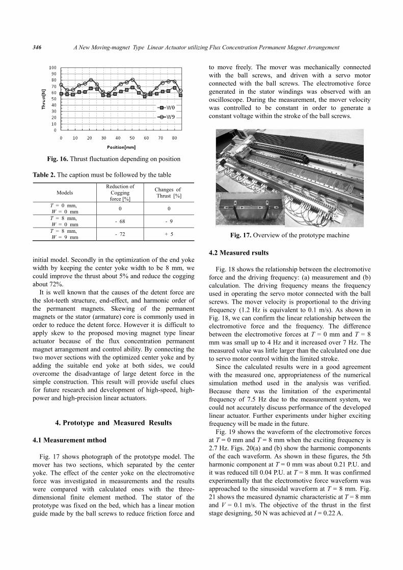
width Fig. 16 shows the comparison of the thrust fluctuations
at W = 0 mm and W = 9 mm in a half period from 0 to 90 electrical degrees. The fluctuations at W = 0 mm and W = 9 mm are similar and the amplitude at W = 9 mm was slightly increased in comparison with that of W = 0 mm
In Table 2, we summarize the results obtained in the optimization of the center and end yoke width. Firstly we optimized only the center yoke width. The cogging force was about 68% reduced, however at the same time the thrust also reduced about 9% in companion of that of the
A New Moving-magnet Type Linear Actuator utilizing Flux Concentration Permanent Magnet Arrangement
346
initial model. Secondly in the optimization of the end yoke width by keeping the center yoke width to be 8 mm, we could improve the thrust about 5% and reduce the cogging about 72%.
It is well known that the causes of the detent force are the slot-teeth structure, end-effect, and harmonic order of the permanent magnets. Skewing of the permanent magnets or the stator (armature) core is commonly used in order to reduce the detent force. However it is difficult to apply skew to the proposed moving magnet type linear actuator because of the flux concentration permanent magnet arrangement and control ability. By connecting the two mover sections with the optimized center yoke and by adding the suitable end yoke at both sides, we could overcome the disadvantage of large detent force in the simple construction. This result will provide useful clues for future research and development of high-speed, high-power and high-precision linear actuators.
4. Prototype and Measured Results
4.1 Measurement mthod Fig. 17 shows photograph of the prototype model. The
mover has two sections, which separated by the center yoke. The effect of the center yoke on the electromotive force was investigated in measurements and the results were compared with calculated ones with the three-dimensional finite element method. The stator of the prototype was fixed on the bed, which has a linear motion guide made by the ball screws to reduce friction force and
to move freely. The mover was mechanically connected with the ball screws, and driven with a servo motor connected with the ball screws. The electromotive force generated in the stator windings was observed with an oscilloscope. During the measurement, the mover velocity was controlled to be constant in order to generate a constant voltage within the stroke of the ball screws.
Fig. 17. Overview of the prototype machine
4.2 Measured rsults
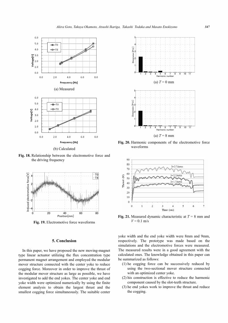
Fig. 18 shows the relationship between the electromotive
force and the driving frequency: (a) measurement and (b) calculation. The driving frequency means the frequency used in operating the servo motor connected with the ball screws. The mover velocity is proportional to the driving frequency (1.2 Hz is equivalent to 0.1 m/s). As shown in Fig. 18, we can confirm the linear relationship between the electromotive force and the frequency. The difference between the electromotive forces at T = 0 mm and T = 8 mm was small up to 4 Hz and it increased over 7 Hz. The measured value was little larger than the calculated one due to servo motor control within the limited stroke.
Since the calculated results were in a good agreement with the measured one, appropriateness of the numerical simulation method used in the analysis was verified. Because there was the limitation of the experimental frequency of 7.5 Hz due to the measurement system, we could not accurately discuss performance of the developed linear actuator. Further experiments under higher exciting frequency will be made in the future.
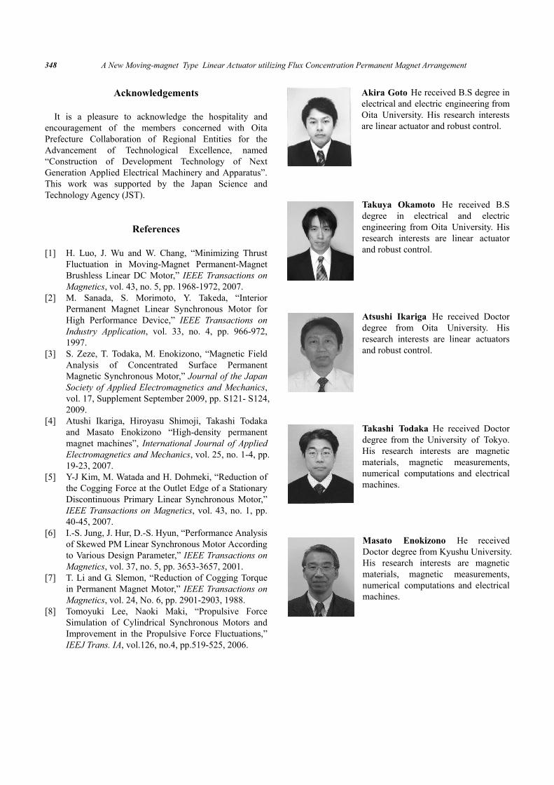
Fig. 19 shows the waveform of the electromotive forces at T = 0 mm and T = 8 mm when the exciting frequency is 2.7 Hz. Figs. 20(a) and (b) show the harmonic components of the each waveform. As shown in these figures, the 5th harmonic component at T = 0 mm was about 0.21 P.U. and it was reduced till 0.04 P.U. at T = 8 mm. It was confirmed experimentally that the electromotive force waveform was approached to the sinusoidal waveform at T = 8 mm. Fig. 21 shows the measured dynamic characteristic at T = 8 mm and V = 0.1 m/s. The objective of the thrust in the first stage designing, 50 N was achieved at I = 0.22 A.
Fig. 16. Thrust fluctuation depending on position
Table 2. The caption must be followed by the table
Models Reduction of
Cogging force [%]
Changes of Thrust [%]
T = 0 mm, W = 0 mm 0 0
T = 8 mm, W = 0 mm - 68 - 9
T = 8 mm, W = 9 mm - 72 + 5
Akira Goto, Takuya Okamoto, Atsushi Ikariga, Takashi Todaka and Masato Enokizono
347
(a) Measured
(b) Calculated
Fig. 18. Relationship between the electromotive force and the driving frequency
0 20 40 60 80
-4
-2
0
2
4
Position[mm]
Indu
ced
ele
ctr
om
otive
forc
e[V
]
T0T8
Fig. 19. Electromotive force waveforms
5. Conclusion In this paper, we have proposed the new moving-magnet
type linear actuator utilizing the flux concentration type permanent magnet arrangement and employed the modular mover structure connected with the center yoke to reduce cogging force. Moreover in order to improve the thrust of the modular mover structure as large as possible, we have investigated to add the end yokes. The center yoke and end yoke width were optimized numerically by using the finite element analysis to obtain the largest thrust and the smallest cogging force simultaneously. The suitable center
yoke width and the end yoke width were 8mm and 9mm, respectively. The prototype was made based on the simulations and the electromotive forces were measured. The measured results were in a good agreement with the calculated ones. The knowledge obtained in this paper can be summarized as follows:
(1) he cogging force can be successively reduced by using the two-sectional mover structure connected with an optimized center yoke.
(2) his construction is effective to reduce the harmonic component caused by the slot-teeth structure.
(3) he end yokes work to improve the thrust and reduce the cogging.
1 2 3 4 5 6 7 8 9 10 110
1
2
3
4
5
Harmonic number
Dim
ensi
on [
P.U
.]
(a) T = 0 mm
1 2 3 4 5 6 7 8 9 10 110
1
2
3
4
5
Harmonic number
Dim
ensi
on [
P.U
.]
(a) T = 8 mm
Fig. 20. Harmonic components of the electromotive force waveforms
Fig. 21. Measured dynamic characteristic at T = 8 mm and V = 0.1 m/s
A New Moving-magnet Type Linear Actuator utilizing Flux Concentration Permanent Magnet Arrangement
348
Acknowledgements It is a pleasure to acknowledge the hospitality and
encouragement of the members concerned with Oita Prefecture Collaboration of Regional Entities for the Advancement of Technological Excellence, named “Construction of Development Technology of Next Generation Applied Electrical Machinery and Apparatus”. This work was supported by the Japan Science and Technology Agency (JST).
References
[1] H. Luo, J. Wu and W. Chang, “Minimizing Thrust Fluctuation in Moving-Magnet Permanent-Magnet Brushless Linear DC Motor,” IEEE Transactions on Magnetics, vol. 43, no. 5, pp. 1968-1972, 2007.
[2] M. Sanada, S. Morimoto, Y. Takeda, “Interior Permanent Magnet Linear Synchronous Motor for High Performance Device,” IEEE Transactions on Industry Application, vol. 33, no. 4, pp. 966-972, 1997.
[3] S. Zeze, T. Todaka, M. Enokizono, “Magnetic Field Analysis of Concentrated Surface Permanent Magnetic Synchronous Motor,” Journal of the Japan Society of Applied Electromagnetics and Mechanics, vol. 17, Supplement September 2009, pp. S121- S124, 2009.
[4] Atushi Ikariga, Hiroyasu Shimoji, Takashi Todaka and Masato Enokizono “High-density permanent magnet machines”, International Journal of Applied Electromagnetics and Mechanics, vol. 25, no. 1-4, pp. 19-23, 2007.
[5] Y-J Kim, M. Watada and H. Dohmeki, “Reduction of the Cogging Force at the Outlet Edge of a Stationary Discontinuous Primary Linear Synchronous Motor,” IEEE Transactions on Magnetics, vol. 43, no. 1, pp. 40-45, 2007.
[6] I.-S. Jung, J. Hur, D.-S. Hyun, “Performance Analysis of Skewed PM Linear Synchronous Motor According to Various Design Parameter,” IEEE Transactions on Magnetics, vol. 37, no. 5, pp. 3653-3657, 2001.
[7] T. Li and G. Slemon, “Reduction of Cogging Torque in Permanent Magnet Motor,” IEEE Transactions on Magnetics, vol. 24, No. 6, pp. 2901-2903, 1988.
[8] Tomoyuki Lee, Naoki Maki, “Propulsive Force Simulation of Cylindrical Synchronous Motors and Improvement in the Propulsive Force Fluctuations,” IEEJ Trans. IA, vol.126, no.4, pp.519-525, 2006.
Akira Goto He received B.S degree in electrical and electric engineering from Oita University. His research interests are linear actuator and robust control.
Takuya Okamoto He received B.S degree in electrical and electric engineering from Oita University. His research interests are linear actuator and robust control.
Atsushi Ikariga He received Doctor degree from Oita University. His research interests are linear actuators and robust control.
Takashi Todaka He received Doctor degree from the University of Tokyo. His research interests are magnetic materials, magnetic measurements, numerical computations and electrical machines.
Masato Enokizono He received Doctor degree from Kyushu University. His research interests are magnetic materials, magnetic measurements, numerical computations and electrical machines.