
A new method for developing structural and material...
14
1 2012 Ohio State University Injury Biomechanics Symposium This paper has not been peer- reviewed. A new method for developing structural and material clavicle response corridors for axial compression and three point bending loading Qi Zhang 1 , Jason Kerrigan 1 , Matt Kindig 2 , Zuoping Li 3 , Jeff Crandall 1 1 University of Virginia, 2 Rehabilitation Institute of Chicago , 3 Humanetics Inc ABSTRACT A number of clavicle finite element (FE) models have been developed to study clavicle injuries in automotive side and frontal crashes. However, no loading response corridors exist in the literature for clavicle FE model validation. Therefore, the purpose of this study was to develop the clavicle response corridors for axial compression and three point bending, which were shown to represents the clavicle loading condition in side and frontal crashes respectively. Ten clavicles were loaded to failure in each of these two loading configurations at strain rates measured in sled tests. Both structural response (force VS deflection) and material response (force VS peak strain) corridors were developed for use in validating clavicle model loading response and injury prediction capacity. The method for creating both structural and material level corridors could be extended to develop corridors for other components of human body. INTRODUCTION Clavicle injuries are fairly common during automotive accidents. Over 9700 occupants restrained by a three-point-belt sustain clavicle fractures every year (Kemper, 2009). It was also reported that 66% of shoulder injuries during car lateral impacts are clavicle fractures (Frampton, 1997). The susceptibility of the clavicle to injury underscores its role as an important loading path during both frontal impact and side impact crashes (Melvin, 1998), since clavicle is loaded directly by shoulder belt in frontal impact and through shoulder in lateral impact crashes. A number of FE models have been developed by researchers to study clavicle and shoulder injuries (Dalmases, 2008; Duprey, 2008; Duprey, 2010; Li, 2012). Although the biomechanical response of the clavicle has been characterized separately under both axial compression loading (Dalmases, 2008; Duprey, 2008) and three point bending (Kemper, 2009; Bolte, 2000), no clavicle response corridor exists in the literature for FE model validation.
-
Upload
dinhkhuong -
Category
Documents
-
view
216 -
download
3
Transcript of A new method for developing structural and material...

1
2012 Ohio State University Injury Biomechanics Symposium
This paper has not been peer- reviewed.
A new method for developing structural and material clavicle
response corridors for axial compression and three point bending
loading
Qi Zhang1, Jason Kerrigan
1, Matt Kindig
2, Zuoping Li
3, Jeff Crandall
1
1 University of Virginia,
2 Rehabilitation Institute of Chicago ,
3 Humanetics Inc
ABSTRACT
A number of clavicle finite element (FE) models have been developed to study clavicle injuries in
automotive side and frontal crashes. However, no loading response corridors exist in the
literature for clavicle FE model validation. Therefore, the purpose of this study was to develop
the clavicle response corridors for axial compression and three point bending, which were
shown to represents the clavicle loading condition in side and frontal crashes respectively. Ten
clavicles were loaded to failure in each of these two loading configurations at strain rates
measured in sled tests. Both structural response (force VS deflection) and material response
(force VS peak strain) corridors were developed for use in validating clavicle model loading
response and injury prediction capacity. The method for creating both structural and material
level corridors could be extended to develop corridors for other components of human body.
INTRODUCTION
Clavicle injuries are fairly common during automotive accidents. Over 9700 occupants
restrained by a three-point-belt sustain clavicle fractures every year (Kemper, 2009). It was also
reported that 66% of shoulder injuries during car lateral impacts are clavicle fractures (Frampton,
1997). The susceptibility of the clavicle to injury underscores its role as an important loading
path during both frontal impact and side impact crashes (Melvin, 1998), since clavicle is loaded
directly by shoulder belt in frontal impact and through shoulder in lateral impact crashes.
A number of FE models have been developed by researchers to study clavicle and
shoulder injuries (Dalmases, 2008; Duprey, 2008; Duprey, 2010; Li, 2012). Although the
biomechanical response of the clavicle has been characterized separately under both axial
compression loading (Dalmases, 2008; Duprey, 2008) and three point bending (Kemper, 2009;
Bolte, 2000), no clavicle response corridor exists in the literature for FE model validation.

2
2012 Ohio State University Injury Biomechanics Symposium
This paper has not been peer- reviewed.
Most of the corridors that exist in the literature were reported in terms of structural
behavior, e.g., force-deflection (Lobdell, 1973; Kerrigan, 2003; Ivarsson, 2005). However, such
a structural description has been shown to be often insufficient for the development of models
which accurately predict fracture timing. Untaroiu et al. (2006) showed that, for example, it is
possible to tune a FE model of the femur to match an experimental force-deflection response
well with both an elastic-plastic and elastic-transversely isotropic material model; however,
neither of these models were capable of predicting experimental bone surface strains, and the
choice of material model can substantially affect the strain response prediction. Since strain
threshold are often used to predict fracture in FE models, structural response validation is
insufficient for fracture prediction. Thus, an FE model that can accurately predict structural
response and surface strain provide for a much useful tool in injury risk modeling.
In this study, structural and material response corridors for axial compression and three-
point bending of the clavicle to failure were developed to assist in FE model development and
response validation. Component tests were used for the clavicle to ensure boundary condition
represent clavicle response under belted shoulder loading in frontal and side impact sled. Ten
clavicles were tested in each configuration. And the force-deflection and force-peak strain
corridors were developed for each condition.
METHODS
1.1 Sled Test and clavicle loading condition identification
Side and frontal sled tests in this study were conducted to justify loading conditions for
clavicle component level tests, 1) loading rate (strain rate), 2) loading directions (the neutral axis
orientation). To characterize these loading conditions, a methodology based on bone surface
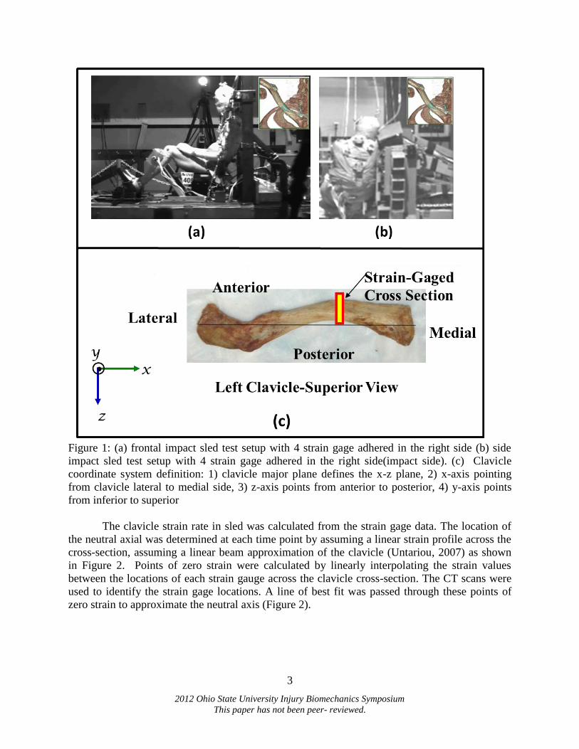
strain measurement (Untariou, 2007) was used. Four uni-axial strain gages were installed around
the perimeter of the clavicle cross-section at the location of maximum posterior concavity of the
clavicle (Figure 1). This location was chosen because it is easily identifiable on the clavicle and
failures most often occur in the middle third of the clavicle. The clavicle coordinate system (CS)
was defined in this study (both sled test and component test) for convenience of expressing the
neutral axis orientation (Figure 1c).
The side impact sled test was conducted at lateral impact speed of 4.3m/s using a rigid
wall mounted to a massive 1700 kg rail mounted sled with a mid-sized male cadaver. The strain
gages were installed on the clavicle of the impact side. The frontal impact sled test was
conducted at an impact speed of 40km/h with a mid-sized male cadaver. The strain gages were
installed on the clavicle which was loaded by three point seat belt. The general methodology for
the side and frontal impact tests closely followed the methods utilized in previous experiments
conducted at the University of Virginia (Lessley, 2010, Lopez-Valdes, 2010).
3
2012 Ohio State University Injury Biomechanics Symposium
This paper has not been peer- reviewed.
Figure 1: (a) frontal impact sled test setup with 4 strain gage adhered in the right side (b) side
impact sled test setup with 4 strain gage adhered in the right side(impact side). (c) Clavicle
coordinate system definition: 1) clavicle major plane defines the x-z plane, 2) x-axis pointing
from clavicle lateral to medial side, 3) z-axis points from anterior to posterior, 4) y-axis points
from inferior to superior
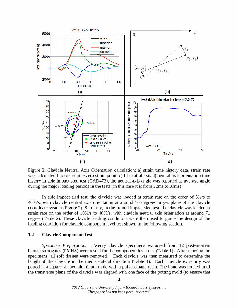
The clavicle strain rate in sled was calculated from the strain gage data. The location of
the neutral axial was determined at each time point by assuming a linear strain profile across the
cross-section, assuming a linear beam approximation of the clavicle (Untariou, 2007) as shown
in Figure 2. Points of zero strain were calculated by linearly interpolating the strain values
between the locations of each strain gauge across the clavicle cross-section. The CT scans were
used to identify the strain gage locations. A line of best fit was passed through these points of
zero strain to approximate the neutral axis (Figure 2).
4
2012 Ohio State University Injury Biomechanics Symposium
This paper has not been peer- reviewed.
Figure 2: Clavicle Neutral Axis Orientation calculation: a) strain time history data, strain rate
was calculated f; b) determine zero strain point; c) fit neutral axis d) neutral axis orientation time
history in side impact sled test (CAD473), the neutral axis angle was reported as average angle
during the major loading periods in the tests (in this case it is from 22ms to 30ms)
In side impact sled test, the clavicle was loaded at strain rate on the order of 5%/s to
40%/s, with clavicle neutral axis orientation at around 76 degrees in y-z plane of the clavicle
coordinate system (Figure 2). Similarly, in the frontal impact sled test, the clavicle was loaded at
strain rate on the order of 10%/s to 40%/s, with clavicle neutral axis orientation at around 71
degree (Table 2). These clavicle loading conditions were then used to guide the design of the
loading condition for clavicle component level test shown in the following section.
1.2 Clavicle Component Test
Specimen Preparation. Twenty clavicle specimens extracted from 12 post-mortem
human surrogates (PMHS) were tested for the component level test (Table 1). After thawing the
specimens, all soft tissues were removed. Each clavicle was then measured to determine the
length of the clavicle in the medial-lateral direction (Table 1). Each clavicle extremity was
potted in a square-shaped aluminum mold with a polyurethane resin. The bone was rotated until
the transverse plane of the clavicle was aligned with one face of the potting mold (to ensure that
5
2012 Ohio State University Injury Biomechanics Symposium
This paper has not been peer- reviewed.
the anterior, superior, posterior, and inferior aspects of the bone were aligned with the mold
edges), and the loading is applied within the clavicle major plane(x-z plane) (Figure 3a). This
will ensure the component level tests to be able to replicate similar loading conditions as the sled
test according to our component tests pilot design.
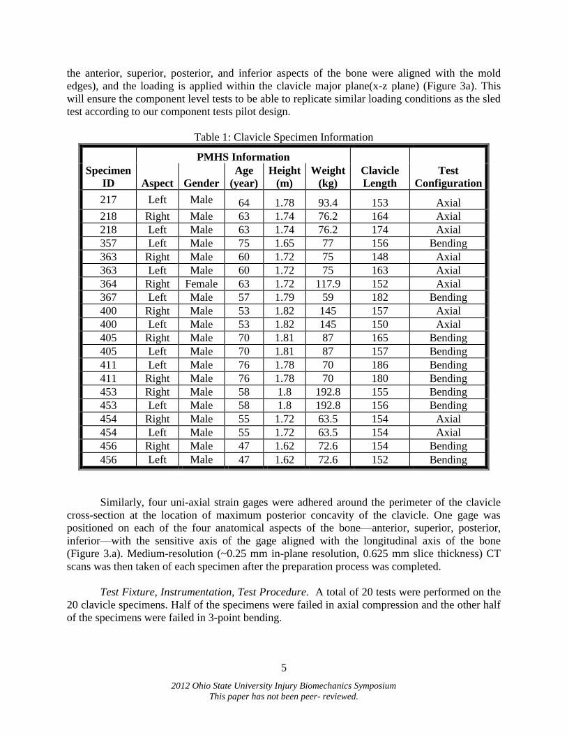
Table 1: Clavicle Specimen Information
Specimen
ID
PMHS Information
Clavicle
Length
Test
Configuration Aspect Gender
Age
(year)
Height
(m)
Weight
(kg)
217 Left Male 64 1.78 93.4 153 Axial
218 Right Male 63 1.74 76.2 164 Axial
218 Left Male 63 1.74 76.2 174 Axial
357 Left Male 75 1.65 77 156 Bending
363 Right Male 60 1.72 75 148 Axial
363 Left Male 60 1.72 75 163 Axial
364 Right Female 63 1.72 117.9 152 Axial
367 Left Male 57 1.79 59 182 Bending
400 Right Male 53 1.82 145 157 Axial
400 Left Male 53 1.82 145 150 Axial
405 Right Male 70 1.81 87 165 Bending
405 Left Male 70 1.81 87 157 Bending
411 Left Male 76 1.78 70 186 Bending
411 Right Male 76 1.78 70 180 Bending
453 Right Male 58 1.8 192.8 155 Bending
453 Left Male 58 1.8 192.8 156 Bending
454 Right Male 55 1.72 63.5 154 Axial
454 Left Male 55 1.72 63.5 154 Axial
456 Right Male 47 1.62 72.6 154 Bending
456 Left Male 47 1.62 72.6 152 Bending
Similarly, four uni-axial strain gages were adhered around the perimeter of the clavicle
cross-section at the location of maximum posterior concavity of the clavicle. One gage was
positioned on each of the four anatomical aspects of the bone—anterior, superior, posterior,
inferior—with the sensitive axis of the gage aligned with the longitudinal axis of the bone
(Figure 3.a). Medium-resolution (~0.25 mm in-plane resolution, 0.625 mm slice thickness) CT
scans was then taken of each specimen after the preparation process was completed.
Test Fixture, Instrumentation, Test Procedure. A total of 20 tests were performed on the
20 clavicle specimens. Half of the specimens were failed in axial compression and the other half
of the specimens were failed in 3-point bending.

6
2012 Ohio State University Injury Biomechanics Symposium
This paper has not been peer- reviewed.
Figure 3: (a) Clavicle Potting method in component level test and its loading schematics under
axial and three point bending condition (b) Axial test fixture schematic (c) Bending test fixture
schematic
The axial test fixture provided a pinned boundary condition at the medial end of the
specimen and a fixed (cantilever) boundary condition at the lateral end (Figure 3b). The medial
end was attached to a metal cup which was permitted to rotate about the superior-inferior axis
only. The lateral end was clamped to the piston of a servo-hydraulic testing machine to prevent
rotation. A 6-axis load cell and a rotational potentiometer were located on the medial end
assembly to measure reaction force and rotation of the end. A uni-axial load cell was installed
7
2012 Ohio State University Injury Biomechanics Symposium
This paper has not been peer- reviewed.
between the actuator and lateral potting block. The actuator was displaced at 100 mm/sec to a
maximum displacement of 30 mm to ensure gross failure of the specimen and to achieve similar
clavicle loading rate as in the side impact sled.
For the bending tests, each end of the clavicle was supported by a similar pinned
assembly which permitted rotation about the superior-inferior axis (Figure 3c). No other rotation
or translation of the ends was permitted; note that this boundary condition allows for three-point
bending where the compressive/tensile forces are not release. A 12.7mm-diameter cylindrical
section of aluminum loaded the clavicle midway along its length to failure; this loader was
attached to the Instron piston. 6-axis load cells measured the reaction force at each end, and
rotational potentiometers measured the rotation of each end. The loader was displaced at 100
mm/sec up to at least 60 mm to ensure gross failure of the specimen and to achieve similar
clavicle loading rate as in the frontal impact sled.
Data Analysis. For the axial loading tests, only the force in the direction of loading was
considered. For the bending tests, the applied bending moment was calculated by averaging the
products of proximal and distal moment arms with the vertical shear forces from loadcell1 and
loadcell2 (Figure 3), assuming the contribution from the force in horizontal direction is
insignificant , considering that the moment arm for the horizontal force is very small. An
effective stiffness K was calculated as the slope of the linear curve fitted in the displacement and
force response between the onset of loading and the time of fracture. In order to verify the
loading condition of the component test, the strain rate and neutral axis orientation was
calculated for each test from the 4 strain gage data with the same method and clavicle coordinate
system definition as the sled test (Figure 1, 2).
To develop force-strain based response corridors, the peak strain along the strain gauge
cross-section will be calculated, as the peak strain gives more useful information to verify the
injury prediction capability of a FE model. To calculate peak strain, the point that is farthest from
the neutral axis line was identified and the peak longitudinal strain on the strain gauge cross
section can be calculated (Untaroiu, 2007). It should be noted that the peak strain location in the
strain gauge cross-section varies with increasing displacement of the loader.
Data Scaling and Corridor Development. To minimize the variations in subject response
due to individual geometry and material properties, the mechanical response data (force,
deflection, strain) were first scaled to the response of a standard subject. Assuming the
specimens are geometrically similar, the mechanical responses were scaled to a reference size
subject responses using a scale factor
based on the length of clavicle specimen ( is
the clavicle length of a standard 50th male measured from the GHBMC model mm).
The scaling factor for strain is 1 because strain is dimensionless metric.
𝐹 𝐹
𝐷𝑖𝑠𝑝 𝐷𝑖𝑠𝑝
8
2012 Ohio State University Injury Biomechanics Symposium
This paper has not been peer- reviewed.
𝑆𝑡𝑟𝑎𝑖𝑛 𝑆𝑡𝑟𝑎𝑖𝑛
With these scaled response data, both elliptical-based (Ash, 2012) and rectangular-based
(Lessley, 2004) corridor development method were used in this study to build the corridors. In
this study, force-deflection and force-peak strain corridors were developed for both the axial
compression and three-point bending tests.
RESULTS
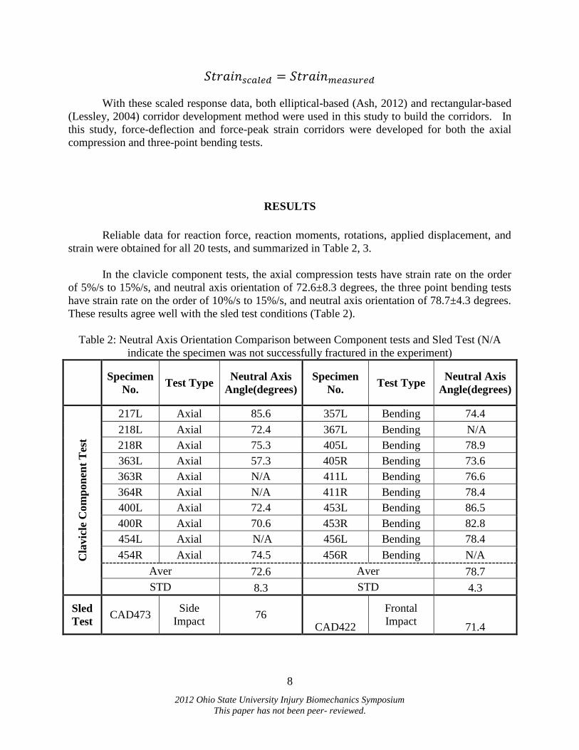
Reliable data for reaction force, reaction moments, rotations, applied displacement, and
strain were obtained for all 20 tests, and summarized in Table 2, 3.
In the clavicle component tests, the axial compression tests have strain rate on the order
of 5%/s to 15%/s, and neutral axis orientation of 72.6±8.3 degrees, the three point bending tests
have strain rate on the order of 10%/s to 15%/s, and neutral axis orientation of 78.7±4.3 degrees.
These results agree well with the sled test conditions (Table 2).
Table 2: Neutral Axis Orientation Comparison between Component tests and Sled Test (N/A
indicate the specimen was not successfully fractured in the experiment)
Specimen
No. Test Type
Neutral Axis
Angle(degrees)
Specimen
No. Test Type
Neutral Axis
Angle(degrees)
Cla
vic
le C
om
pon
ent
Test
217L Axial 85.6 357L Bending 74.4
218L Axial 72.4 367L Bending N/A
218R Axial 75.3 405L Bending 78.9
363L Axial 57.3 405R Bending 73.6
363R Axial N/A 411L Bending 76.6
364R Axial N/A 411R Bending 78.4
400L Axial 72.4 453L Bending 86.5
400R Axial 70.6 453R Bending 82.8
454L Axial N/A 456L Bending 78.4
454R Axial 74.5 456R Bending N/A
Aver 72.6 Aver 78.7
STD 8.3 STD 4.3
Sled
Test CAD473
Side
Impact 76
CAD422
Frontal
Impact 71.4

9
2012 Ohio State University Injury Biomechanics Symposium
This paper has not been peer- reviewed.
The average stiffness was 440±164 N/mm for the axial loading tests, and 199±38 N/mm
for the three point bending tests. The fracture force of the axial loading tests was 2966±800N,
while the fracture force of three point bending tests was 1053±231 N (Table 3).
Table 3: Summary for component clavicle failure tests (N/A indicate the specimen was not
successfully fractured in the experiment)
Axial Compression Loading Three Point Bending
Clavicle Stiffness
(N/mm) Dfrac
(mm) Ffrac
(N) Clavicle
Stiffness
(N/mm) Dfrac
(mm) Ffrac
(N)
217L 852.7 4.28 3138 357L 159.1 5.25 701
218L 500.5 5.09 2368 367L 168.3 4.9613 691
218R 641.9 5.234 2295 405L 218.6 5.836 1085
363L 444.5 6.56 2183 405R 197.2 6.804 1144
363R 449.3 5.924 2468 411L 161.8 7.9 1062
364R 384.7 13 4391 411R 172.8 6.89 917
400L 240 N/A N/A 453L 240.6 7.005 1346
400R 396.8 10.82 4104 453R 275.8 4.233 1043
454L 502.9 7.34 3238 456L 208.9 7.783 1361
454R 436.7 11 2781 456R 185 7.275 1180
AVERAGE 485.0 7.7 2966 AVERAGE 198.8 6.39 1053
STDEV 164.5 3.3 800 STDEV 37.9 1.25 231
The structural level and material level corridors for the axial and three point bending tests
were presented in Figure 4, 5, 6, 7. The red curve is the corridor by ellipse-based method, while
the green curve is by rectangular-based method.

10
2012 Ohio State University Injury Biomechanics Symposium
This paper has not been peer- reviewed.
Figure 4: Clavicle force vs deflection response corridor for axial compression test.
Figure 5: Clavicle moment vs deflection response corridor for three point bending test.

11
2012 Ohio State University Injury Biomechanics Symposium
This paper has not been peer- reviewed.
Figure 2: Clavicle peak strain vs force response corridor for axial compression test
Figure 3: Clavicle peak strain vs force response corridor for three point bending test
DISCUSSION
While the biomechanical response of the clavicle has been characterized separately under
axial compression (Dalmases, 2008, Duprey, 2008) and three point bending (Kemper, 2009,
Bolte, 2000), none of this studies have justified their choice of loading conditions. In the current

12
2012 Ohio State University Injury Biomechanics Symposium
This paper has not been peer- reviewed.
study, by carefully designing to replicate the clavicle loading condition that experienced in a
typical side or frontal impact, the clavicle component level tests give us a higher confidence on
its validity.
The average stiffness for axial loading tests (439.5±164N/mm) was lower than that in the
Dalmase`s study (786±258N/mm). The average bending stiffness for three point bending test
(199±38 N/mm) was higher than the stiffness measured in Kemper`s study (127±43N/mm). This
may be due to the age of the PMHS used in this study (61 ± 8.7years old) is lower than Kemper`s
study (72.7 ± 15 years old).
The fracture force (2966+800N) in the axial compression tests is much higher than the
results from Dalmases et al. (2008) and Duprey et. al (2008). However, the loading rate in
Dalmases`s study is significantly lower than this study (0.63 mm/s vs 100 mm/s). And Duprey et.
al.(2008) , use specimens which are much older than this study (Duprey used subjects aged
78±12 years), and a pronounced different boundary condition. The Duprey`s study used a ball-
and socket joint on the two clavicle ends, allowing for rotation about all three axes rather than
the single axis used in the present study. The fracture force (1053±231 N) in the three point
bending test is higher than the fracture force in Kemper`s three point bending tests (644±216 N),
which again maybe because of the age difference.
Although response corridors for FE model validation have been established for several
other parts of the human body, such as the thorax (Lobdell, 1973), the lower extremity (Kerrigan,
2003; Ivarsson, 2005), all of these corridors are structural response corridors (force vs.
deflection). The material-level (eg. strain) corridors developed in the current study can provide
higher confidence when validating a FE model, and therefore give a higher ability to predict
injury.
CONCLUSIONS
20 clavicle dynamic axial compression and three-point bending failure tests with
representative loading condition of side and frontal impact sled test were performed. The
mechanical response data (eg. force, displacement) were reported in the study. In addition, force
vs. deflection and force vs. peak strain corridors were developed for these two loading
configurations. The results of this study are useful for clavicle FE model loading response
validation. In addition, the force vs. peak strain corridor development method could also be
extended to develop corridors for other components of the human body.
REFERENCES
BOLTE, J.H., HINES, M.H., McFADDEN, J.D., SAUL, R.A. (2000). Shoulder Response
Characteristics and Injury Due to Lateral Glenohumeral Joint Impacts. Proc. 44th
Stapp
Car Crash Conference, Paper No. 00S-11, 261-280.

13
2012 Ohio State University Injury Biomechanics Symposium
This paper has not been peer- reviewed.
ASH.JH, LESSLEY.DJ, FORMAN. JL, ZHANG.Q, SHAW.CG, CRANDALL. JR(2012).
Whole-Body Kinematics: Response Corridors for Restrained PMHS in Frontal Impacts.
International Conference on the Biomechanics of Impact .
BOLTE, J., HINES, M., MCFADDEN, J., & SAUL, R. (2000). Shoulder response characteristics
and injury due to lateral glenohumeral joint impacts. Stapp Car Crash Journal, 44, 261–
280.
DUPREY S, BRUYERE K, VERIEST JP. (2008) Influence of Geometrical Personalization on
the Simulation of Clavicle Fractures. Journal of Biomechanics Vol.41
DUPREY S, BRUYERE K, VERRIEST, JP(2010) Clavicle Fracture Prediction: Simulation of
Shoulder Lateral Impacts With Geometrically Personalized Finite Elements Models. The
Journal of Trauma, Injury, Infection, and critical Care. Volume 68(1).
FRAMPTON, R.J., MORRIS, A.P., THOMAS, P.,BODIWALA, G.G. (1997). An overview of
upper extremity injuries to car occupants in UK vehicles crashes. Proc IRCOBI
Conference, 37--52.
B. Johan Ivarsson, Jason R. Kerrigan, David J. Lessley, D. Chris Drinkwater, Check Y. Kam,
Drew B. Murphy, Jeff R. Crandall, and Richard W. Kent(2005) Dynamic Response
Corridors of the Human Thigh and Leg in Non-Midpoint Three-Point Bending. Paper
2005-01-0305, Society of Automotive Engineers.
KEMPER A, STITZEL J, GABLER C, DUMA S. (2009) Biomechanical Response of the
Human Clavicle: The Effects of Loading Direction on Bending Properties. Journal of
Applied Biomechanics, 2009, 25, 165-174
KERRIGAN, J, BHALLA, J, MADELEY, N, CRANDALL, J, DENG, B. (2003) Response
Corridors for the Human Leg in 3-Point Lateral Bending. The 7th US National Congress
on Computational Mechanics.
LESSLEY D, CRANDALL J, SHAW G, KENT R, FUNK J (2004) Normalization Technique
for Developing Corridors from Individual Subject Responses. Paper 2004-01-0288,
Society of Automotive Engineers.
LESSLEY, DJ, SHAW, CG, PARENT, DP, ARREGUI-DALMASES, C, KINDIG, M, RILEY,
P, PURTSEZOV, S, SOCHOR, M, GOCHENOUR, T, BOLTON, JR, SUBIT, D,
CRANDALL, JR, TAKAYAMA, S, ONO, K, KAMIJI, K, YASUKI, T. (2010) Whole-
body response to pure lateral impact. Stapp Car Crash Journal, 53.
ZUOPING LI, MATTHEW W. KINDIG, JASON R. KERRIGAN, RICHARD W. KENT &
JEFF R. CRANDALL (2012): Development and validation of a subject-specific finite
element model of a human clavicle, Computer Methods in Biomechanics and Biomedical
Engineering, DOI:10.1080/10255842.2011.641122
14
2012 Ohio State University Injury Biomechanics Symposium
This paper has not been peer- reviewed.
LÓPEZ-VALDÉS, FJ, LAU, AG, LAMP, J, RILEY, PO, LESSLEY, DJ, DAMON, AM,
KINDIG, MW, KENT, RW, BALASUBRAMANIAN, S, SEACRIST, T, MALTESE,
MR, ARBOGAST, KB, HIGUCHI, K, TANJI, H. (2010) Analysis of Spinal Motion and
Loads During Frontal Impacts. Comparison between PMHS and ATD. Annals of
Advances in Automotive Medicine (AAAM), 54.
LOBDELL, T.E., KROELL, C.K. SCHNEIDER, D.C. AND HERING, W.E. (1973) Impact
Response of the Human Thorax. in Human Impact Response: Measurement and
Simulation; Proceedings, William F. King and Harold J. Mertz (eds.), pp. 201-245.
Plenum Press, New York, NY.
MELVIN, J., BARON, K., LITTLE, W., GIDEON, T.W.,PIERCE, J. (1998). Biomechanical
analysis of Indy race car crashes. Proceeding 42nd STAPP Car Crash Conference, p337.d
UNTAROIU DC, KERRIGAN.JR, CRANDALL.JR(2006) Material Identification using
Successive Response Surface Methodology, with Application to a Human Femur
subjected to Three-Point Bending Loading. Paper 2006-01-0063, Society of Automotive
Engineers.
UNTAROIU DC, KERRIGAN JR, KAM, C, CRANDALL JR, YAMAZAKI, K,
FUKUYAMA, K, KAMIJI, K, YASUKI, TSUYOSHI(2007) Correlation of Strain and
Loads Measured in the Long Bones with Observed Kinematics of the Lower Limb during
Vehicle-Pedestrian Impacts. Stapp Car Crash Journal, Vol. 51 (October 2007)