
A New Fuzzy Sliding Mode Controller for Induction … design of a near-optimal fuzzy sliding mode...
6
Abstract— The drawbacks of sliding mode control in terms of high control gains and chattering are overcome by merging of the FLC with the variable structure of the SMC to form a fuzzy sliding mode controller (FSMC). However, the major drawback of fuzzy control is the lack of design techniques. Hence this hybrid system increases the complexity in design and, at present, there exists no effective design tools due to the lack of analytical and numerical approaches. This paper develops an automated design approach to this design problem, using a genetic algorithm. The method is illustrated through the design of a near-optimal fuzzy sliding mode controller for induction motor speed control. The control strategy gives a relatively low overshoots with smooth control action and retains robustness of the sliding mode approach. I. INTRODUCTION Indirect field-oriented techniques are now widely used for the control of induction motor in high-performance applications. With this control strategy, the decoupled control of IM is guaranteed, and can be controlled and provide the same performance as achieved from a separately excited DC machine. However, the control performances of the resulted linear system are still influenced by the uncertainties, which usually are composed of unpredictable parameter variations, external load disturbances. Therefore, in order to solve some of the problems of field-oriented control, the motor drive must be techniques that are appropriate to discontinuous operation of the switching devices and allow the robustness of the algorithm, with regard to changing parameters and external disturbances. This common drawback can be overcome by using variable structure control (VSC). The variable structure strategy using the sliding mode (SMC) has been the focus of many studies and research for the control of the AC drive. The goal of the VSC is to constrain the system trajectory to the sliding surface via the use of the appropriate switching logic. The sliding mode control can offer good properties, such as insensitivity to parameter variations, external disturbance rejection, and fast dynamics response. However, in SMC, the high frequency chattering phenomenon that results from the discontinuous control action is a severe problem when the state of the system is close to the sliding surface. In various nonlinear system control issues, fuzzy controller is recently a popular method to combine with sliding mode control method that can improve some disadvantages in this issue. Comparing with the classical control theory, the fuzzy control theory does not pay much attention to the stability of system, and the stability of the controlled system cannot be so guaranteed. In fact, the stability is observed based on following two assumptions: First, the input/output data and system parameters must be crisply known. Second, the system has to be known precisely. The fuzzy controller is weaker in stability because it lacks a strict mathematics model to demonstrate, although many researches show that it can be stabilized anyway [3, 4]. Nevertheless, the concept of a sliding mode controller (SMC) can be employed to be a basis to ensure the stability of the controller. The feature of a smooth control action of FLC can be used to overcome the disadvantages of the SMC systems. This is achieved by merging of the FLC with the variable structure of the SMC to form a Fuzzy Sliding Mode Controller (FSMC) [2, 5]. In this hybrid control system, the strength of the sliding mode control lies in its ability to account for modeling imprecision and external disturbances while the FLC provides better damping and reduced chattering. However, the major drawback of fuzzy control is the lack of design techniques. Most of the fuzzy rules are human knowledge oriented and hence rules will deviate from person to person in spite of the same performance of the system. The selection of suitable fuzzy rules, membership functions and their definitions along the universe of discourse always involve a painstaking trial-and-error process. In this paper, the genetic algorithm (GA) is applied for the automatic design of a fuzzy-sliding mode control system. In this GA based approach, the genetic algorithm (GA) is applied to determine the parameter set, consisting of the width of boundary layer ( φ ) and control gain ( k ) of the fuzzy sliding mode controller. A near-optimal fuzzy sliding mode controller has been achieved, fulfilling the robustness criteria specified in the sliding mode control and yielding a high performance in implementation to induction motor speed control. II. INDIRECT FIELD-ORIENTED CONTROL OF THE IM The induction motor model expressed in terms of the state variables is given by equation (1): A New Fuzzy Sliding Mode Controller for Induction Motor Speed Control. A Hazzab (1) , I.K. Bousserhane (1) , M. Kamli (2) & M. Rahli (2) (1) University Center of Bechar B.P 417 BECHAR (08000) ALGERIA (2) University of Sciences and Technology of Oran, ORAN (31000) ALGERIA E-mails: [email protected], [email protected], [email protected] and [email protected] D
Transcript of A New Fuzzy Sliding Mode Controller for Induction … design of a near-optimal fuzzy sliding mode...
Abstract— The drawbacks of sliding mode control in terms of high control gains and chattering are overcome by merging of the FLC with the variable structure of the SMC to form a fuzzy sliding mode controller (FSMC). However, the major drawback of fuzzy control is the lack of design techniques. Hence this hybrid system increases the complexity in design and, at present, there exists no effective design tools due to the lack of analytical and numerical approaches. This paper develops an automated design approach to this design problem, using a genetic algorithm. The method is illustrated through the design of a near-optimal fuzzy sliding mode controller for induction motor speed control. The control strategy gives a relatively low overshoots with smooth control action and retains robustness of the sliding mode approach.
I. INTRODUCTION Indirect field-oriented techniques are now widely used for the control of induction motor in high-performance applications. With this control strategy, the decoupled
control of IM is guaranteed, and can be controlled and provide the same performance as achieved from a separately excited DC machine. However, the control performances of the resulted linear system are still influenced by the uncertainties, which usually are composed of unpredictable parameter variations, external load disturbances. Therefore, in order to solve some of the problems of field-oriented control, the motor drive must be techniques that are appropriate to discontinuous operation of the switching devices and allow the robustness of the algorithm, with regard to changing parameters and external disturbances. This common drawback can be overcome by using variable structure control (VSC). The variable structure strategy using the sliding mode (SMC) has been the focus of many studies and research for the control of the AC drive. The goal of the VSC is to constrain the system trajectory to the sliding surface via the use of the appropriate switching logic. The sliding mode control can offer good properties, such as insensitivity to parameter variations, external disturbance rejection, and fast dynamics response. However, in SMC, the high frequency chattering phenomenon that results from the discontinuous control action is a severe problem when the state of the system is close to the sliding surface. In various nonlinear system control issues, fuzzy controller is recently a popular method to combine with sliding mode
control method that can improve some disadvantages in this issue. Comparing with the classical control theory, the fuzzy control theory does not pay much attention to the stability of system, and the stability of the controlled system cannot be so guaranteed. In fact, the stability is observed based on following two assumptions: First, the input/output data and system parameters must be crisply known. Second, the system has to be known precisely. The fuzzy controller is weaker in stability because it lacks a strict mathematics model to demonstrate, although many researches show that it can be stabilized anyway [3, 4]. Nevertheless, the concept of a sliding mode controller (SMC) can be employed to be a basis to ensure the stability of the controller. The feature of a smooth control action of FLC can be used to overcome the disadvantages of the SMC systems. This is achieved by merging of the FLC with the variable structure of the SMC to form a Fuzzy Sliding Mode Controller (FSMC) [2, 5]. In this hybrid control system, the strength of the sliding mode control lies in its ability to account for modeling imprecision and external disturbances while the FLC provides better damping and reduced chattering. However, the major drawback of fuzzy control is the lack of design techniques. Most of the fuzzy rules are human knowledge oriented and hence rules will deviate from person to person in spite of the same performance of the system. The selection of suitable fuzzy rules, membership functions and their definitions along the universe of discourse always involve a painstaking trial-and-error process.
In this paper, the genetic algorithm (GA) is applied for the automatic design of a fuzzy-sliding mode control system. In this GA based approach, the genetic algorithm (GA) is applied to determine the parameter set, consisting of the width of boundary layer (φ ) and control gain ( k ) of the fuzzy sliding mode controller. A near-optimal fuzzy sliding mode controller has been achieved, fulfilling the robustness criteria specified in the sliding mode control and yielding a high performance in implementation to induction motor speed control.
II. INDIRECT FIELD-ORIENTED CONTROL OF THE IM The induction motor model expressed in terms of the state variables is given by equation (1):
A New Fuzzy Sliding Mode Controller for Induction Motor Speed Control.
A Hazzab (1), I.K. Bousserhane (1), M. Kamli (2) & M. Rahli (2) (1) University Center of Bechar B.P 417 BECHAR (08000) ALGERIA
(2) University of Sciences and Technology of Oran, ORAN (31000) ALGERIA E-mails: [email protected], [email protected], [email protected] and [email protected]
D
( )
( )
1- 1-
1- 1- - -
1- -
1- - -
sd s m m rsd e sq rd rq sd
s r s r r s r s
sq s m r me sd sq rd rq sq
s r s r s r r s
rd msd rd e r rq
r r
rq msq e r rd rq
r r
di R L Li i V
dt L L L L L L
di R L LI I V
dt L L L L L Ld L
idt
d Li
dt
d
ωσ ω ψ ψσ στ σ τ σ σ
ωσω ψ ψσ στ σ σ τ σ
ψψ ω ω ψ
τ τψ
ω ω ψ ψτ τ
ω
⎛ ⎞= + + + + +⎜ ⎟
⎝ ⎠⎛ ⎞
= + + +⎜ ⎟⎝ ⎠
= +
=
( )2
- - -m crsq rd sd rq r l
r
p L f pi i Tdt JL J J
ψ ψ ω
⎧⎪⎪⎪⎪⎪⎪⎪⎨⎪⎪⎪⎪⎪⎪ =⎪⎩
(1)
Where σ is the coefficient of dispersion and is given by (2):
2
1 m
s r
LL L
σ = − (2)
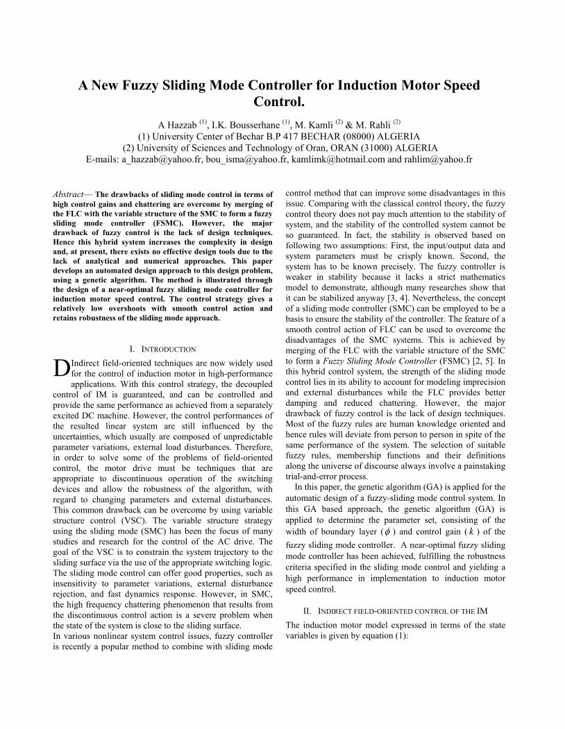
The main objective of the vector control of induction motors is, as in DC machines, to independently control the torque and the flux; this is done by using a d-q rotating reference frame synchronously with the rotor flux space vector [6, 7] as shown in fig. 1, the d axis is aligned with the rotor flux space vector. Under this condition we have: * 0rqψ = and
* *rd rψ ψ= .
For the ideal state decoupling the torque equation become analogous to the dc machine as follows:
32
m re
r
P LT
Lψ⋅ ⋅
= (3)
And the slip frequency can be given as follow: *
*
1 sqsl
r sd
ii
ωτ
= (4)
Consequently, the dynamic equations (1) yield:
2*
1- 1-
1- 1- - -
1-
32
sd s msd e sq rd sd
s r s r r s
sq s m re sd sq rd sq
s r s r s
mrsd rd
r r
m crsq rd r l
r
di R Li i V
dt L L L L
di R Li i V
dt L L L LLd
idt
p L fd pi Tdt JL J J
σ ω ψσ στ σ τ σ
ωσω ψσ στ σ σ
ψψ
τ τ
ωψ ω
⎧ ⎛ ⎞= + + + +⎪ ⎜ ⎟
⎪ ⎝ ⎠⎪ ⎛ ⎞⎪ = + +⎜ ⎟⎪⎪ ⎝ ⎠⎨⎪ =⎪⎪⎪
= − −⎪⎪⎩
(5)
The decoupling control method with compensation is to choose inverter output voltages such that:
( )* * *1sd p i sd sd e s sqV K K i i L i
sω σ⎛ ⎞= + − −⎜ ⎟
⎝ ⎠ (6)
( )* * *1 msq p i sq sq e s sd e rd
r
LV K K i i L i
s Lω σ ω ψ⎛ ⎞= + − + +⎜ ⎟
⎝ ⎠(7)
Fig. 2 shows the implemented diagram of an induction motor indirect field-oriented control (IFOC) [4,6].
III. SLIDING MODE CONTROL
A Sliding Mode Controller is a Variable Structure Controller (VSC). Basically, a VSC includes several different continuous functions that can map plant state to a control surface, and the switching among different functions is determined by plant state that is represented by a switching function [2]. Without lost of generality, consider the design of a sliding mode controller for the following second order system: Here we assume 0b > . ( )u t is the input to the system. The following is a possible choice of the structure of a sliding mode controller [1, 5, 9]:
sgn( ) equ k s u= − ⋅ + (8)
Where equ is called equivalent control which is used when
the system state is in the sliding mode [1]. k is a constant and it is the maximal value of the controller output. s is called switching function because the control action switches its sign on the two sides of the switching surface
0s = . s is defined as [1,9]: s e eλ= +& (9) Where *e x x= − and *x is the desired state. λ is a constant. sgn( )s is a sign function, which is defined as:
1 if 0sgn( )
1 if 0s
ss
− <⎧= ⎨ >⎩
(10)
The control strategy adopted here will guarantee the system trajectories move toward and stay on the sliding surface
0s = from any initial condition if the following condition meets: ss sη≤ −& (11) Where η is a positive constant that guarantees the system trajectories hit the sliding surface in finite time [1, 2, 5]. Using a sign function often causes chattering in practice. One solution is to introduce a boundary layer around the switch surface [5]:
s equ u u= + (12)
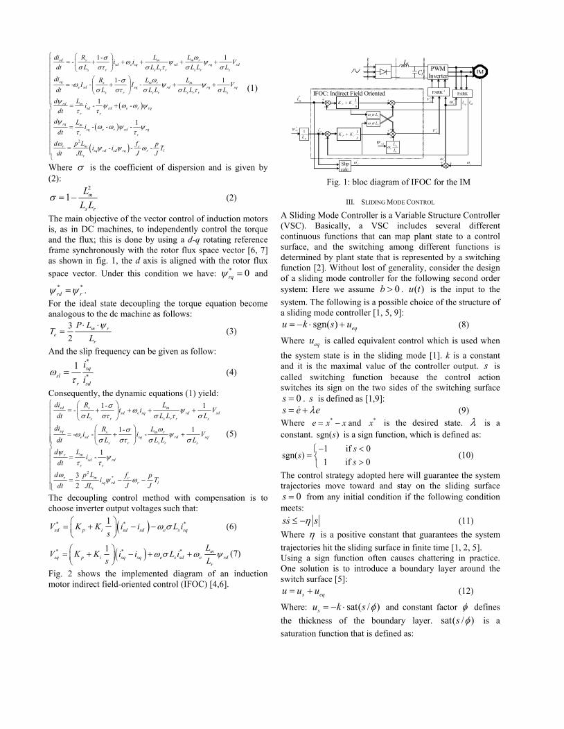
Where: sat( / )su k s φ= − ⋅ and constant factor φ defines the thickness of the boundary layer. sat( / )s φ is a saturation function that is defined as:
Fig. 1: bloc diagram of IFOC for the IM
IMPWM Inverter
PARK-1
Cf
Lf
PARKIFOC: Indirect Field Oriented
-
*sqi 1
P iK Ks
+
1P iK K
s+
sdisqi
*sdi
*rdψ
*eω
1
mL
e sLω σ
-
e sLω σ
me
r
LL
ωrdψ
*sdV
*sqV
Slip calc.
*eω
*slω rω
+
+ +
+ -
+
+ +
k
k/2
0
-k/2
-k 1.5φ− φ− 0.5φ− 1.5φφ0.5φ0
Fig. 3: The first part (us) of the SMC k
k/2
0
-k/2
-k 1.5φ− φ− 0.5φ− 1.5φφ0.5φ0
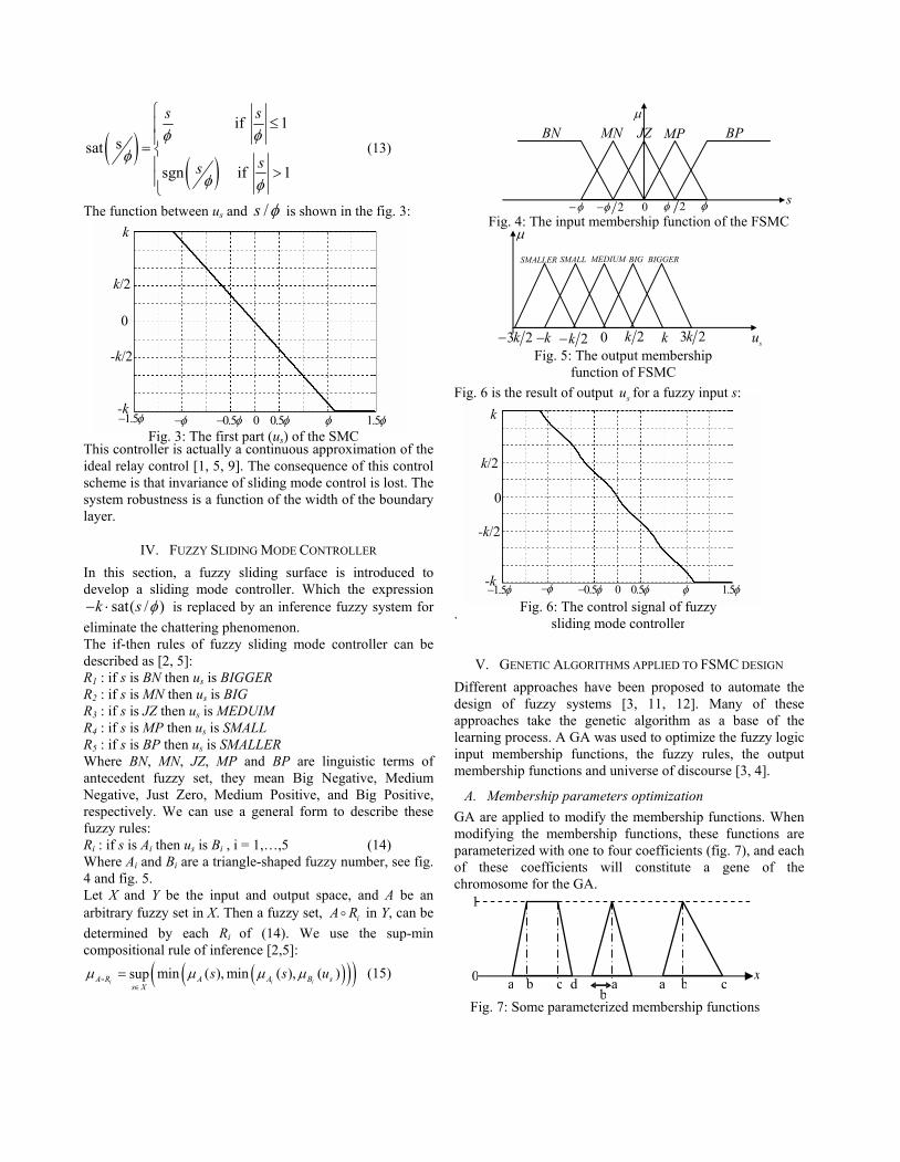
Fig. 6: The control signal of fuzzy sliding mode controller
( )( )
if 1ssat
sgn if 1
s s
ss
φ φφ
φ φ
⎧≤⎪
⎪= ⎨⎪ >⎪⎩
(13)
The function between us and /φs is shown in the fig. 3:
This controller is actually a continuous approximation of the ideal relay control [1, 5, 9]. The consequence of this control scheme is that invariance of sliding mode control is lost. The system robustness is a function of the width of the boundary layer.
IV. FUZZY SLIDING MODE CONTROLLER In this section, a fuzzy sliding surface is introduced to develop a sliding mode controller. Which the expression
sat( / )k s φ− ⋅ is replaced by an inference fuzzy system for eliminate the chattering phenomenon. The if-then rules of fuzzy sliding mode controller can be described as [2, 5]: R1 : if s is BN then us is BIGGER R2 : if s is MN then us is BIG R3 : if s is JZ then us is MEDUIM R4 : if s is MP then us is SMALL R5 : if s is BP then us is SMALLER Where BN, MN, JZ, MP and BP are linguistic terms of antecedent fuzzy set, they mean Big Negative, Medium Negative, Just Zero, Medium Positive, and Big Positive, respectively. We can use a general form to describe these fuzzy rules: Ri : if s is Ai then us is Bi , i = 1,…,5 (14) Where Ai and Bi are a triangle-shaped fuzzy number, see fig. 4 and fig. 5. Let X and Y be the input and output space, and A be an arbitrary fuzzy set in X. Then a fuzzy set, iA Ro in Y, can be determined by each Ri of (14). We use the sup-min compositional rule of inference [2,5]:
( )( )( )min ( ), min ( ), ( )supi i iA R A A B s
s Xs s uµ µ µ µ
∈=o (15)
Fig. 6 is the result of output su for a fuzzy input s: .
V. GENETIC ALGORITHMS APPLIED TO FSMC DESIGN Different approaches have been proposed to automate the design of fuzzy systems [3, 11, 12]. Many of these approaches take the genetic algorithm as a base of the learning process. A GA was used to optimize the fuzzy logic input membership functions, the fuzzy rules, the output membership functions and universe of discourse [3, 4].
A. Membership parameters optimization GA are applied to modify the membership functions. When modifying the membership functions, these functions are parameterized with one to four coefficients (fig. 7), and each of these coefficients will constitute a gene of the chromosome for the GA.
µ JZ MP BPMN BN
φ− 2φ− 0 2φ φ s
Fig. 4: The input membership function of the FSMC
Fig. 5: The output membership function of FSMC
µ
SMALLER
k− su
SMALL MEDIUM BIG BIGGER
2k− 0 2k k3 2k− 3 2k
Fig. 7: Some parameterized membership functions a b c d a a b c
x0
1
b
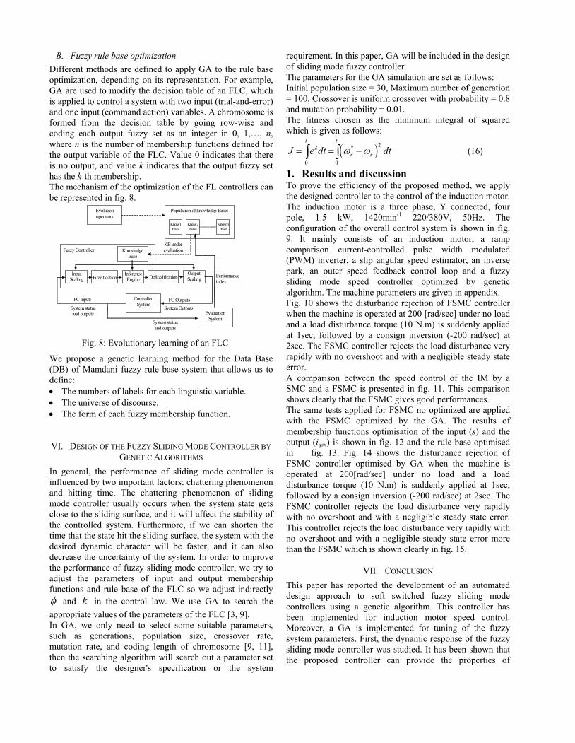
Fig. 8: Evolutionary learning of an FLC
Evolution operators
Population of knowledge Bases
Know1 Base
Know2Base
KnownBase
Knowledge Base
Fuzzification Inference Engine Defuzzification
Output Scaling
Controlled System
Evaluation System
Input Scaling
Fuzzy Controller KB under evaluation
Performance index
FC Outputs System Outputs
FC inputs
System status and outputs
System status and outputs
B. Fuzzy rule base optimization Different methods are defined to apply GA to the rule base optimization, depending on its representation. For example, GA are used to modify the decision table of an FLC, which is applied to control a system with two input (trial-and-error) and one input (command action) variables. A chromosome is formed from the decision table by going row-wise and coding each output fuzzy set as an integer in 0, 1,…, n, where n is the number of membership functions defined for the output variable of the FLC. Value 0 indicates that there is no output, and value k indicates that the output fuzzy set has the k-th membership. The mechanism of the optimization of the FL controllers can be represented in fig. 8.
We propose a genetic learning method for the Data Base (DB) of Mamdani fuzzy rule base system that allows us to define: • The numbers of labels for each linguistic variable. • The universe of discourse. • The form of each fuzzy membership function.
VI. DESIGN OF THE FUZZY SLIDING MODE CONTROLLER BY GENETIC ALGORITHMS
In general, the performance of sliding mode controller is influenced by two important factors: chattering phenomenon and hitting time. The chattering phenomenon of sliding mode controller usually occurs when the system state gets close to the sliding surface, and it will affect the stability of the controlled system. Furthermore, if we can shorten the time that the state hit the sliding surface, the system with the desired dynamic character will be faster, and it can also decrease the uncertainty of the system. In order to improve the performance of fuzzy sliding mode controller, we try to adjust the parameters of input and output membership functions and rule base of the FLC so we adjust indirectly φ and k in the control law. We use GA to search the appropriate values of the parameters of the FLC [3, 9]. In GA, we only need to select some suitable parameters, such as generations, population size, crossover rate, mutation rate, and coding length of chromosome [9, 11], then the searching algorithm will search out a parameter set to satisfy the designer's specification or the system
requirement. In this paper, GA will be included in the design of sliding mode fuzzy controller. The parameters for the GA simulation are set as follows: Initial population size = 30, Maximum number of generation = 100, Crossover is uniform crossover with probability = 0.8 and mutation probability = 0.01. The fitness chosen as the minimum integral of squared which is given as follows:
( )22 *
0 0
t t
r rJ e dt dtω ω= = −∫ ∫ (16)
1. Results and discussion To prove the efficiency of the proposed method, we apply the designed controller to the control of the induction motor. The induction motor is a three phase, Y connected, four pole, 1.5 kW, 1420min-1 220/380V, 50Hz. The configuration of the overall control system is shown in fig. 9. It mainly consists of an induction motor, a ramp comparison current-controlled pulse width modulated (PWM) inverter, a slip angular speed estimator, an inverse park, an outer speed feedback control loop and a fuzzy sliding mode speed controller optimized by genetic algorithm. The machine parameters are given in appendix. Fig. 10 shows the disturbance rejection of FSMC controller when the machine is operated at 200 [rad/sec] under no load and a load disturbance torque (10 N.m) is suddenly applied at 1sec, followed by a consign inversion (-200 rad/sec) at 2sec. The FSMC controller rejects the load disturbance very rapidly with no overshoot and with a negligible steady state error. A comparison between the speed control of the IM by a SMC and a FSMC is presented in fig. 11. This comparison shows clearly that the FSMC gives good performances. The same tests applied for FSMC no optimized are applied with the FSMC optimized by the GA. The results of membership functions optimisation of the input (s) and the output (iqsn) is shown in fig. 12 and the rule base optimised in fig. 13. Fig. 14 shows the disturbance rejection of FSMC controller optimised by GA when the machine is operated at 200[rad/sec] under no load and a load disturbance torque (10 N.m) is suddenly applied at 1sec, followed by a consign inversion (-200 rad/sec) at 2sec. The FSMC controller rejects the load disturbance very rapidly with no overshoot and with a negligible steady state error. This controller rejects the load disturbance very rapidly with no overshoot and with a negligible steady state error more than the FSMC which is shown clearly in fig. 15.
VII. CONCLUSION This paper has reported the development of an automated design approach to soft switched fuzzy sliding mode controllers using a genetic algorithm. This controller has been implemented for induction motor speed control. Moreover, a GA is implemented for tuning of the fuzzy system parameters. First, the dynamic response of the fuzzy sliding mode controller was studied. It has been shown that the proposed controller can provide the properties of
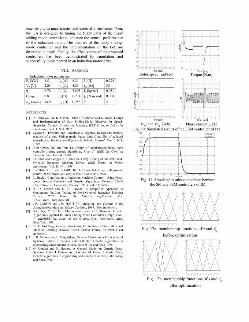
Fig. 11: Simulated results comparison between the SM and FSM controllers of IM.
Fig. 12b: membership functions of s and ssqi
after optimization
Fig. 12a: membership functions of s and ssqi
before optimization
insensitivity to uncertainties and external disturbance. Then, the GA is designed to tuning the fuzzy parts of the fuzzy sliding mode controller to enhance the control performance of the induction motor. The theories of the fuzzy sliding-mode controller and the implementation of the GA are described in detail. Finally, the effectiveness of the proposed controllers has been demonstrated by simulation and successfully implemented in an induction motor drive.
VIII. APPENDIX Induction motor parameters:
Pn [kW] 1.5 Ian [A] 6.31 Ls [H] 0.274Vn [V] 220 Rs [Ω] 4.85 ƒn [Hz] 50 η 0.78 Rr [Ω] 3.805 Jn [kg/m2] 0.031 Cosϕn 0.8 Lr [H] 0.274 ƒc [N.m.s/rd] 0.008
ωn[tr/min] 1428 Lm [H] 0.258 P 2
REFERENCES [1] A. Derdiyok, M. K. Guven, Habib-Ur Rahman and N. Inane, Design
and Implementation of New Sliding-Mode Observer for Speed-Sensorless Control of Induction Machine, IEEE Trans. on Industrial Electronics, Vol. 1. N°3, 2002.
[2] Spyros G. Tzafestas and Gerosimos G. Rigatos, Design and stability analysis of a new Sliding mode Fuzzy logic Controller of reduced Complexity, Machine Intelligence & Robotic Control, Vol. 1 N°1, 1999.
[3] Kim Chwee NG and Yun LI, Design of sophisticated fuzzy logic controllers using genetic algorithms, Proc. 3rd IEEE Int. Conf. on Fuzzy Systems, Orlando, 1994.
[4] LI Zhen and Longya XU, On-Line Fuzzy Tuning of Indirect Field-Oriented Induction Machine Drives, IEEE Trans. on Power Electronics, Vol. 13 N°1, 1998.
[5] JI-CHANG LE and YA-HU KUO, Decoupled fuzzy sliding-mode control, IEEE Trans. on Fuzzy Systems, Vol. 6 N°3, 1998.
[6] L. Baghli, Contribution to Induction Machine Control: Using Fuzzy Logic, Neural Networks and Genetic Algorithms, Doctoral Thesis Henri Poincaré University, January 1999. (Text in French.).
[7] R. D. Lorenz and D. B. Lawson, A Simplified Approach to Continuous On-Line Tuning of Field-Oriented Induction Machine Drives, IEEE Trans. On Industry application, Vol. N°26, Issue/3, May-June 90.
[8] J.P. CARON and J.P. HAUTIER, Modeling and Control of the Asynchronous Machine, Edition Technip., 1995. (Text in French).
[9] K.C. Ng, Y. Li, D.J. Murray-Smith and K.C. Sharman, Genetic Algorithms Applied to Fuzzy Sliding Mode Controller Design, Proc. 1st IEE/IEEE Int. Conf. on GA in Eng. Syst., Innovation, Appl. Scheffield 1995.
[10] D. E. Goldberg, Genetic algorithms, Exploration, Optimization and Machine Learning, Addison-Wesley Edition, France, SA 1994. (Text in French).
[11] J. R. Velasco and L. Magedalena, Genetic Algorithm in Fuzzy Control Systems, Editor J. Periaux and G.Winter, Genetic algorithms in engineering and computer science, John Wiley and Sons, 1995.
[12] O. Cordon and F. Herrera, A General Study on Genetic Fuzzy Systems, Editor J. Periaux and G.Winter, M. Galan, P. Custa (Eds.), Genetic algorithms in engineering and computer science, John Wiley and Sons, 1995.
Fig. 10: Simulated results of the FSM controller of IM
Time [sec]
ψrd
and
ψrq
[Wb]
rdψ and rqψ [Wb]Time [sec]
I a [A
]
Phase current ia [A]
Time [sec]
ωr
Rotor speed [rad/sec]Time [sec]
T e [N
.m]
Torque [N.m]
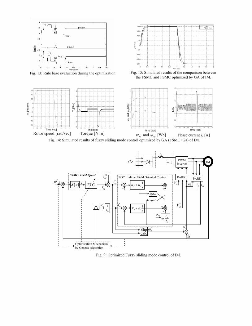
Fig. 15: Simulated results of the comparison between the FSMC and FSMC optimized by GA of IM.
Rule5
Rule4
Rule3
Rule2
Rule1
Rul
es
Fig. 13: Rule base evaluation during the optimization
Fig. 14: Simulated results of fuzzy sliding mode control optimized by GA (FSMC+Ga) of IM.
Time [sec]ψ
rd a
nd ψ
rq [W
b]
Time [sec]
I a [A
]
Phase current ia [A] Time [sec]
ωr [
rad/
sec]
Rotor speed [rad/sec] Time [sec]
T e [N
.m]
Torque [N.m] rdψ and rqψ [Wb]
Fig. 9: Optimized Fuzzy sliding mode control of IM.
ssqi
IMPWM Inverter
PARK-1
Cf
Lf
PARK IFOC: Indirect Field Oriented Control
-
*sqi 1
P iK Ks
+
1P iK K
s+
sdisqi
*sdi*
rdψ
*eω
1
mL
e sLω σ
-
e sLω σ
me
r
LL
ωrdψ
*sdV
*sqV
Slipcalc
*eω*
slω
rω
++
++
FLC ( )S e
eqsqi
*rω
FSMC: FSM Speed
+++
-
Optimization Mechanism by Genetic Algorithm
s
++


![Robust Fuzzy-Second Order Sliding Mode based …thesai.org/...Robust_Fuzzy_Second_Order_Sliding_Mode_based...Con… · Robust Fuzzy-Second Order Sliding Mode based ... [3]. Sliding-mode](https://static.fdocuments.net/doc/165x107/5b7a16407f8b9a483c8b5dce/robust-fuzzy-second-order-sliding-mode-based-robust-fuzzy-second-order-sliding.jpg)


![Fuzzy-Identification-Based Adaptive Sliding-Mode …...sliding-mode control. Several model-free approaches based on adaptive control [2, 3], fuzzy control [4, 5] and neural network](https://static.fdocuments.net/doc/165x107/5f2a38e8df8d5f40631ca5af/fuzzy-identification-based-adaptive-sliding-mode-sliding-mode-control-several.jpg)