A New Electric Brush Cutter - wseas.org New Electric Brush Cutter ... electronic control board...
12
A New Electric Brush Cutter CHIEH-TSUNG CHI Department of Electrical Engineering, Chienkuo Technology University No. 1, Chieh Shou N. Rd., Changhua City, Taiwan, R.O.C. E-mail: [email protected] Abstract: - To integrate power electronic control technology into the most mechanical mechanism of conventional internal combustion engine type has made it possible to design and implement a new electric brush cutter with blade rotation speed control and electronic circuit protection functions. The mechanical power source of tradition mechanical grass cutter is based on a two or four strokes petrol engine. To obtain some very attracting advantages such as low vibration and acoustic noise, free of air pollution and low using cost, a DC motor is used as the mechanical power source of new electric type brush cutter. In addition, a Li-ion battery and electronic control board designed for DC motor speed control and circuit protection purposes were included as well. Designing ideas and the working principle of respective circuit in electronic control board will be explained. The performances of the proposed electric brush cutter were validated through extensive experiments and a laboratory scale implementation. Key-Words: - Internal combustion engine, Electric brush cutter, DC motor, Li-ion battery 1 Introduction Traditionally, the internal combustion engine type has been used to drive the mower requiring the human operation. It, however, may suffer from the drawback such as both time and energy consumption. Based on the modern concept, the development of modern system should consider manpower saving and avoid excessive energy consumption. Unfortunately, many systems such as traditional lawn mowers consume more power and result in greenhouse effect. This problem should be resolved by the academia and industry [1],[7-12]. In the past decade years, almost the main mechanical power source of blade of the conventional brush cutter was driven by two or four strokes internal combustion engine. Has larger instantaneous output mechanical power of engine makes that each type of engine is suit for many types of customer tools. Especially, many applications needs larger mechanical power output. The fuel of general internal combustion engine is gasoline and engine oil. As we known, the economic is increasingly development in the world, the total necessary quantity of fuel such as gasoline is certainly increased and the using days of fuel is shortened as well [2-6]. More fuel is used, more air pollution is made. Warm effect become a critical problem in the world, the average temperature in earth is increasing year by year. More and more people realize this series problem [6]. Some real actions should be done right away. To overcome the expensive using cost and the carbon dioxide released problems, there have been concerned by many countries in the recent years. In the manufacturing fields of the brush cutter, several types of new brush cutter were made based on electric power. According to the different application fields, the supplying electric power of brush cutter may be alternating current or direct current source and stand alone or not etc. [4]. This paper aims at developing a new electric brush cutter associated with high performances such as low noise and vibration, easy move and start, less malfunction and compact. The mechanical power of the internal combustion engine in conventional brush cutter is replaced by a DC brush motor (abbreviated as DC motor) here. To use electric power as the supply source of the brush cutter, therefore, it is almost free of carbon released and low electric energy is dissipated in normal operation process. No air and environmental pollution problem like internal combustion engine used will be happened again. The needed electric energy of this new electric brush cutter is mainly supplied with a rechargeable lion battery. Through the measuring estimation, the charging cost of battery per using time is generally lower than that needed by the internal combustion engine type. Several superior functions are included in the new electric brush cutter which never be found in conventional engine type, for example, high-speed and power- saving mode selection, status display, clockwise and WSEAS TRANSACTIONS on SYSTEMS and CONTROL Chieh-Tsung Chi E-ISSN: 2224-2856 75 Issue 3, Volume 7, July 2012
Transcript of A New Electric Brush Cutter - wseas.org New Electric Brush Cutter ... electronic control board...
A New Electric Brush Cutter
CHIEH-TSUNG CHIDepartment of Electrical Engineering, Chienkuo Technology University
No. 1, Chieh Shou N. Rd., Changhua City, Taiwan, R.O.C.E-mail: [email protected]
Abstract: - To integrate power electronic control technology into the most mechanical mechanism ofconventional internal combustion engine type has made it possible to design and implement a new electricbrush cutter with blade rotation speed control and electronic circuit protection functions. The mechanical powersource of tradition mechanical grass cutter is based on a two or four strokes petrol engine. To obtain some veryattracting advantages such as low vibration and acoustic noise, free of air pollution and low using cost, a DCmotor is used as the mechanical power source of new electric type brush cutter. In addition, a Li-ion battery andelectronic control board designed for DC motor speed control and circuit protection purposes were included aswell. Designing ideas and the working principle of respective circuit in electronic control board will beexplained. The performances of the proposed electric brush cutter were validated through extensiveexperiments and a laboratory scale implementation.
Key-Words: - Internal combustion engine, Electric brush cutter, DC motor, Li-ion battery
1 IntroductionTraditionally, the internal combustion engine typehas been used to drive the mower requiring thehuman operation. It, however, may suffer from thedrawback such as both time and energyconsumption. Based on the modern concept, thedevelopment of modern system should considermanpower saving and avoid excessive energyconsumption. Unfortunately, many systems such astraditional lawn mowers consume more power andresult in greenhouse effect. This problem should beresolved by the academia and industry [1],[7-12].
In the past decade years, almost the mainmechanical power source of blade of theconventional brush cutter was driven by two or fourstrokes internal combustion engine. Has largerinstantaneous output mechanical power of enginemakes that each type of engine is suit for manytypes of customer tools. Especially, manyapplications needs larger mechanical power output.The fuel of general internal combustion engine isgasoline and engine oil. As we known, the economicis increasingly development in the world, the totalnecessary quantity of fuel such as gasoline iscertainly increased and the using days of fuel isshortened as well [2-6]. More fuel is used, more airpollution is made. Warm effect become a criticalproblem in the world, the average temperature inearth is increasing year by year. More and morepeople realize this series problem [6]. Some realactions should be done right away. To overcome the
expensive using cost and the carbon dioxidereleased problems, there have been concerned bymany countries in the recent years. In themanufacturing fields of the brush cutter, severaltypes of new brush cutter were made based onelectric power. According to the differentapplication fields, the supplying electric power ofbrush cutter may be alternating current or directcurrent source and stand alone or not etc. [4].
This paper aims at developing a new electricbrush cutter associated with high performances suchas low noise and vibration, easy move and start, lessmalfunction and compact. The mechanical power ofthe internal combustion engine in conventionalbrush cutter is replaced by a DC brush motor(abbreviated as DC motor) here. To use electricpower as the supply source of the brush cutter,therefore, it is almost free of carbon released andlow electric energy is dissipated in normal operationprocess. No air and environmental pollutionproblem like internal combustion engine used willbe happened again. The needed electric energy ofthis new electric brush cutter is mainly suppliedwith a rechargeable lion battery. Through themeasuring estimation, the charging cost of batteryper using time is generally lower than that neededby the internal combustion engine type. Severalsuperior functions are included in the new electricbrush cutter which never be found in conventionalengine type, for example, high-speed and power-saving mode selection, status display, clockwise and
WSEAS TRANSACTIONS on SYSTEMS and CONTROL Chieh-Tsung Chi
E-ISSN: 2224-2856 75 Issue 3, Volume 7, July 2012
counter-clockwise control, continuous speed settingcontrol, the over-current and over-temperaturedetection of motor and proper protection abilities.Most of above-mentioned function should be notfound or implemented in the conventional internalcombustion engine brush cutter. For convenientcarrying out experiments, a prototype of the electricbrush cutter has been completed in our laboratory.The feasibility and overall performances of thedeveloped electric brush cutter are validated throughexperiments.
The basic arrangement of this paper was dividedinto six sections. Section 2 develops themathematical model of the proposed electric brushcutter, including the control modules,microcontroller, voltage regulator, sensory circuitsand status display. Section 3 compares themechanical structure features between internalcombustion engine and electric type brush cutter.More descriptions concerning proposed electricbrush cutter will be explored. In the section 4, thedesigning functional structure of electronic controlboard, detailed circuit design and its workingprinciple of each sub-circuit in electronic controlboard will be examined. Section 5 presents theexperimental results and their discussions. Theconclusions are given in section 6.
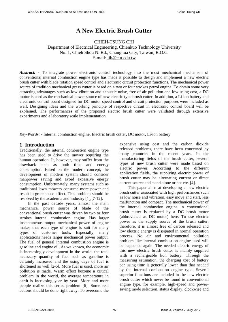
2 Mathematical ModelFor a permanent-magnet brush DC motor, the fluxintensity generated in stator is a constant value. Theblade or motor speed of the proposed electric brushcutter can only be controlled by changing the valueof its applied average armature voltage. If the safeoperation of electric brush cutter is always required;the blade speed must be often controlled under therated motor speed in itself. The larger appliedaverage armature voltage there is, the quicker theblade rotation speed will be. As depicted in Fig. 1,the electric magnetic torque is generated by motorshould be kept constant value through controllingthe current value flowing into the armature of motorat a constant value. The transient response of theelectric brush cutter can be described by electricaland mechanical parts, respectively [7],[8-15]. Fig. 2is a typical equivalent electrical circuit of a motorand included mechanical load. The mathematicalmodel of the electric brush board can be establishedby using this figure.
2.1 Electrical modelIn order to dynamically change the motor speed, themotor will be triggered by PWM signals by
switching the power switch on or off. The dynamicelectrical response of the electric brush cutter can bedescribed by using the Kirchihoff’s voltage law(KVL) and written as follows:
Fig. 1. Armature-voltage and field-flux controlunder rated torque and power.
mM
aaa Kdt
diLiRU (1)
where the meaning of those symbols shown in Equ.(1) are explained in the following:U : the applied armature voltage of motor;
aR : the armature’s resistance of motor;
aL : the armature’s inductance of motor;
Mi : the motor current;K : the emf constant of motor;
m : the speed of the blade.
2.2 Mechanical modelIn theory, the mechanical transient responsedescribed by employing the Newton’s second law isgiven as follows:
mMm BTT
dtd
J
(2)
where the torque MT is torque applied to the load,which depends upon the blade type and lawn status.The generated electrical torque T is related with thecurrent flowing into motor and can be given as:
aKiT (3)
Equation (3) can be substituted into Equ. (2) andthen the result is given as follows:
mMam BTKi
dtd
J (4)
WSEAS TRANSACTIONS on SYSTEMS and CONTROL Chieh-Tsung Chi
E-ISSN: 2224-2856 76 Issue 3, Volume 7, July 2012
The parameters B and J are called as the equivalentviscous coefficient and inertia moment of the brushcutter. The mechanical time constant of the DCmotor can be written by the following formula:
BJ
m (5)
Generally speaking, the mechanical timeconstant is much larger than the electrical timeconstant. This is the reason why the speed or theapplied voltage of the motor can be changed by ahigh frequency switching signal (PWM) throughpower switch.
Fig. 2. Separately excited DC motor or permanent-magnet type DC motor (if the value of flux
intensity is constant).
2.3 Power distribution of input powerIn case of the input power of electric brush cutteris inP , part of this power will be dissipated in each ofelectric circuit and mechanical mechanism bydifferent loss forms. The remaining power is thenused to output or drive the blade to work. Forbrevity, the relation of the input electric power andother loss powers can be expressed as follows (referto Fig. 4):
outoin PPPPPP 321 (6)
where,oP : the power loss occurred in permanent-magnet
DC motor (between point A and B);1P : the power loss occurred in between DC motor
and coupling mechanism (between point B andC);
2P : the equivalent power loss occurred in themechanical transmission shaft tube(betweenpoint C and D);
3P : the equivalent power loss occurred between twosides of gear box(between point D and E);
outP : the power used as for working the brush-cutterblade (after point E);According to equation (6), if the operating
efficiency is hope to be improved, the power loss
occurred in transmission process should be reducedas possible as.
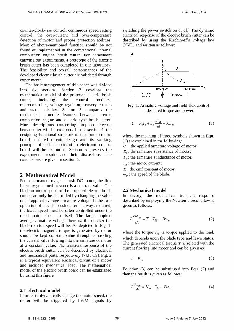
3 Description of Electric Brush CutterFig. 3 shows a typical structure of an internal twostrokes engine brush cutter. The blade of the brushcutter is driven by a two strokes engine. The outputmechanical power of engine is transmitted to thefinal terminal or blade through a couplingmechanism, shaft tube and gear box. In order todynamic change the operating speed of engine,some mechanical control switches such as throttletrigger lockout engine stopping device, accelerationand deceleration operations and so on are arrangedon a bike handle. In general, there is a suspendercarried by operator shoulder will be combined withthe brush cutter by using a hook. The blade (nylonrope or multi-tooth metal plate) is driven by thepetrol engine through some mechanical devices suchas coupling mechanism, shaft tube and gear box.
Fig. 3. Typical appearance of two stokes engine typebrush cutter.
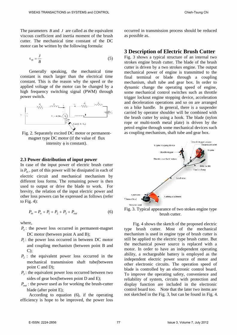
Fig. 4 shows the sketch of the proposed electrictype brush cutter. Most of the mechanicalmechanism is used in engine type of brush cutter isstill be applied to the electric type brush cutter. Butthe mechanical power source is replaced with amotor. In order to have an independent operatingability, a rechargeable battery is employed as theindependent electric power source of motor andother electronic circuits. The operation speed ofblade is controlled by an electronic control board.To improve the operating safety, convenience andreliability of system, circuits with protection anddisplay function are included in the electroniccontrol board too. Note that the later two items arenot sketched in the Fig. 3, but can be found in Fig. 4.
WSEAS TRANSACTIONS on SYSTEMS and CONTROL Chieh-Tsung Chi
E-ISSN: 2224-2856 77 Issue 3, Volume 7, July 2012
Every module cooperates each other and executes agrass cutting task [12],[16-20].
Fig. 4. Sketches the appearance of the proposedelectric brush cutter.
3.1 DC motorAs mentioned earlier, the blade of the petrol enginetype brush cutter is generally driven by an internalcombustion two or four strokes engine. It is replacedby a permanent-magnet DC motor in electric brushcutter. Taken the manufacturing cost and compactsize into consideration, a permanent-magnet andbrush type DC motor is adopted. The magneticintensity of the permanent-magnet DC motor isconstant. So that, the rotation speed of the drivenDC motor or the blade of the brush cutter should becontrolled by the generated magnetic field intensityin the rotor or armature of the DC motor. Generallyspeaking, the complexity of the speed controller forthe permanent-magnet DC motor is generally easierthan the other types of motor and it is cheap. So thatit is adopted as the driven motor of the electric typebrush cutter.
3.2 Rechargeable batteryBecause the proposed electric brush cutter is to haveindependent operation ability, Li-ion rechargeablebattery has some superior features such as highvolume energy rate, allowable cyclic charging timesand energy density; it is very suit for electric typebrush cutter used as its power source. Themechanical size is compact and the total weight islight as well. Especially, the repeat charging times isover one thousands times in theory, therefore, theusing cost is cheaper than other types ofrechargeable battery. The discharging rate isallowed to be over its rated current. Here, a Li-Ion
rechargeable battery with capacity, 4.3 Ah, is usedas the power source of the proposed electric brushcutter under the default using total time andoperating rated current.
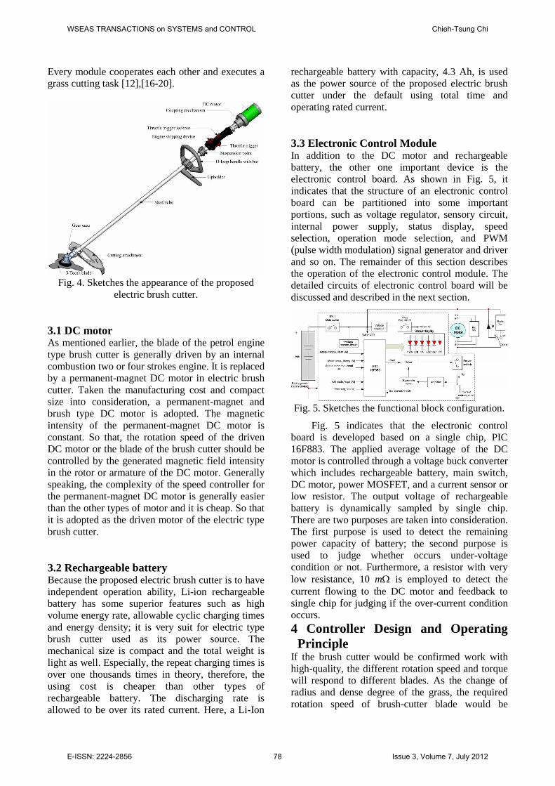
3.3 Electronic Control ModuleIn addition to the DC motor and rechargeablebattery, the other one important device is theelectronic control board. As shown in Fig. 5, itindicates that the structure of an electronic controlboard can be partitioned into some importantportions, such as voltage regulator, sensory circuit,internal power supply, status display, speedselection, operation mode selection, and PWM(pulse width modulation) signal generator and driverand so on. The remainder of this section describesthe operation of the electronic control module. Thedetailed circuits of electronic control board will bediscussed and described in the next section.
Fig. 5. Sketches the functional block configuration.
Fig. 5 indicates that the electronic controlboard is developed based on a single chip, PIC16F883. The applied average voltage of the DCmotor is controlled through a voltage buck converterwhich includes rechargeable battery, main switch,DC motor, power MOSFET, and a current sensor orlow resistor. The output voltage of rechargeablebattery is dynamically sampled by single chip.There are two purposes are taken into consideration.The first purpose is used to detect the remainingpower capacity of battery; the second purpose isused to judge whether occurs under-voltagecondition or not. Furthermore, a resistor with verylow resistance, 10 m is employed to detect thecurrent flowing to the DC motor and feedback tosingle chip for judging if the over-current conditionoccurs.4 Controller Design and OperatingPrinciple
If the brush cutter would be confirmed work withhigh-quality, the different rotation speed and torquewill respond to different blades. As the change ofradius and dense degree of the grass, the requiredrotation speed of brush-cutter blade would be
WSEAS TRANSACTIONS on SYSTEMS and CONTROL Chieh-Tsung Chi
E-ISSN: 2224-2856 78 Issue 3, Volume 7, July 2012
different too. The final output speed of blade isdecided by operator’s experience. In addition to thespeed of blade should be changed dynamically, theprotection of circuits or components and operating
status display are also included in the electroniccontrol board. Take the manufacturing cost intoconsideration, more complicate control approachesare not adopted here [13-16].
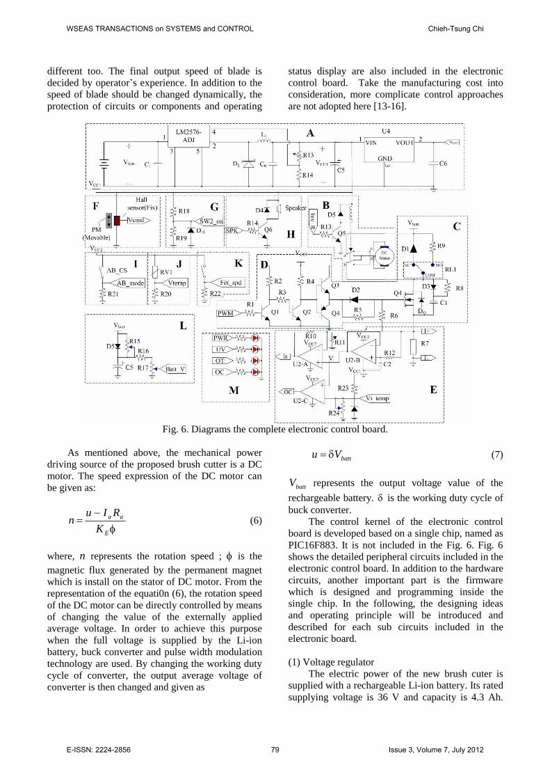
Fig. 6. Diagrams the complete electronic control board.
As mentioned above, the mechanical powerdriving source of the proposed brush cutter is a DCmotor. The speed expression of the DC motor canbe given as:
E
aa
KRIu
n (6)
where, n represents the rotation speed ; is themagnetic flux generated by the permanent magnetwhich is install on the stator of DC motor. From therepresentation of the equati0n (6), the rotation speedof the DC motor can be directly controlled by meansof changing the value of the externally appliedaverage voltage. In order to achieve this purposewhen the full voltage is supplied by the Li-ionbattery, buck converter and pulse width modulationtechnology are used. By changing the working dutycycle of converter, the output average voltage ofconverter is then changed and given as
battVu (7)
battV represents the output voltage value of therechargeable battery. is the working duty cycle ofbuck converter.
The control kernel of the electronic controlboard is developed based on a single chip, named asPIC16F883. It is not included in the Fig. 6. Fig. 6shows the detailed peripheral circuits included in theelectronic control board. In addition to the hardwarecircuits, another important part is the firmwarewhich is designed and programming inside thesingle chip. In the following, the designing ideasand operating principle will be introduced anddescribed for each sub circuits included in theelectronic board.
(1) Voltage regulatorThe electric power of the new brush cuter is
supplied with a rechargeable Li-ion battery. Its ratedsupplying voltage is 36 V and capacity is 4.3 Ah.
WSEAS TRANSACTIONS on SYSTEMS and CONTROL Chieh-Tsung Chi
E-ISSN: 2224-2856 79 Issue 3, Volume 7, July 2012
Although the rated voltage of Li-ion battery is 36 V,the voltage value after even charged is often overthan the rated voltage value of itself. It is often evenover 40 V. To copy with the necessities ofdynamically changing the supplying voltage valueof battery, the real applied average voltage or therotation speed of DC motor is obtained bycontrolling the duty cycle of buck converterdesigned in electronic control board. In addition,two DC power source such as +12 V and +5 V aredesigned to supply with the control and protectioncircuits on the electronic control board.
As shown in part A of Fig. 6, the outputvoltage of battery is connected to the input of avoltage regulator IC, LM2576. The output voltagevalue of the LM2576 can be regulated by user.There is a noticeable requirement is the inputvoltage must be controlled within allowable voltagevalue. Due to peripheral circuits is very simple andinexpensive. Furthermore, another low DC voltagesource +5 V is regulated directly from the +12 V byusing a linear regulation integrated circuit LM7805.Because the DC power source +12 V is obtainedfrom the output voltage of battery by means ofswitching approach, the power loss is much lowerthan that of a linear method used, although thelarger voltage difference between output and inputof regulator exists.
(2) Rotation direction controlAt present, the used type of DC motor belongs
to a separately DC motor. If the rotor rotationdirection of DC motor is required to change, it isonly necessary to change the armature appliedvoltage polarity of the DC motor. As can be seen inpart B of Fig. 6, two electromagnetic DC relays areused to achieve this purpose. It is worthy of payingmore attention to change the contacts of relay forchanging the rotor rotation direction should becompleted before applying voltage to the DC motor.Otherwise, those contacts of relay would be possiblydestroyed due to the high temperature arc. At least,the using life of relay contacts is then shortened.
(3) Braking circuitIn order to improve or strengthen the operating
safety, it is necessary to design a braking circuitwhich is embedded in electronic control board forquickly stopping the rotor rotation of DC motor.Basically, the DC motor itself is a typical feedbacksystem. The polarity of induced voltage across thearmature of DC motor is same as that of externallyapplied voltage (that is battery voltage). If therotation speed of DC motor reduces gradually, theinduced voltage ( EnK ) would be down as well.
Finally, DC motor stops due to no any rotationkinetic energy. As diagrammed in part C of Fig. 6,the armature of DC motor is switched from a wheeldiode to a resistor with low resistance by using anelectromagnetic DC relay RL1 when the appliedbattery voltage source is broken. The remainingrotation kinetic energy of DC motor would bedissipated or transmitted into heat form at the low-resistance resistor. The needed braking time forstopping the DC-motor rotor is effectively shortened.
(4) Driving circuitIn the buck converter, the power MOSFET is
belong to a voltage-controlled device. TheMOSFET will be turned on or off is decided by theapplied gate driving voltage value is +12 V or 0 V.The working power voltage source of most ofcircuits designed on electronic control board is +5 V.There is a less power loss will be dissipated on thepower MOSFET if their gate trigger voltage is highas possible as in theory. Only the applied voltagemust be lower than allowable rated voltage value ofthe used power MOSFET. As shown in part D ofFig. 6, not only the gate turn-on voltage is +12 V,but also is the push-pull driving circuit of powerMOSFET used to promote the driving ability.
(5) Current sensor and amplifier circuitPart E of Fig. 6 shows a resistor with low
resistance R7 (10 m ) in series of the armature ofDC motor is set as a current sensor for dynamicallysensing the motor current. To avoid effecting on theaction of DC motor, the resistance of current sensorshould be designed very low. The default ratedworking current of DC motor only has 10 A.Normally, the voltage-drop value across the currentsensor is very small as well. Before this voltage isread by single chip, it should first be amplified bycircuit. In order to reduce the load effect, the voltagedrop across the current sensor or resistor R7 isamplified by a voltage follower. And the currentsignal is further amplified by a voltage amplifierwhich is composed of a U2-B and some otherpassive components. Here, U2-C and neighbouringsome passive devices are formed as a voltagecomparator. The output of U2-C, OC, will bechanged from low voltage level to high voltage levelwhen the sensed motor’s current is over the defaultcurrent value. The OC signal is used to break thepower MOSFET by hardware. In addition, thisamplified current signal is an analogy signal. Thissignal is read by single chip dynamically. Accordingto this dynamic current value, the working dutycycle of buck converter or the applied average
WSEAS TRANSACTIONS on SYSTEMS and CONTROL Chieh-Tsung Chi
E-ISSN: 2224-2856 80 Issue 3, Volume 7, July 2012
voltage of DC motor will be real-time commandedto adjust by single chip.
(6) Speed commandTo copy with the users’custom, the operating
methods of electric type brush cutter will bedesigned the same as those of applied in internalcombustion engine type brush cutter. Although theappearance and operating method is designed assimilar as, the driving feature is much different fromthe engine type brush cutter. Part F of Fig. 6diagrams acceleration and deceleration mechanismis composed of a hall sensor and a permanent-magnet. The hall sensor is fixed inside theacceleration and deceleration mechanism. Thepermanent-magnet can be moved by following alinear line. The induced voltage value across the hallsensor is proportion to the displacement of thepermanent-magnet. The output induced voltagevalue across the hall sensor will be real-time read bysingle chip. When the single chip reads the inducedvoltage of hall sensor and realizes the equivalentmeaning, it commands to change the rotation speedof DC motor later.
(7) Secondary power switchIn addition to the main or primary power
switch, there is a secondary power is set. Thedesigning purpose is the user of electric brush cutterwho sometimes hopes to stop temporally. As can beseen in part G of Fig. 6, the resistors R18 and R19are formed as a voltage divider. The output voltageof resistor R19 is copy with the digital level. Singlechip only needs to read the voltage level across theresistor R19. The dynamic status of electric brushcutter is obtained by single chip.
(8) SpeakerA speaker shown in Fig. 6 will alarm when
malfunction condition occurred. In order for theoperator or equipment is avoided to be harmed ordestroyed. For example, any malfunctions likeunder-voltage, over-current or waiting time too longand so on occurs, the speaker will be commanded bysingle chip begins to alarm for warning the operator.Generally, the operator should be required to stopworking right away and check the reasons whymalfunction occurs.
(9) A/B mode selectionTo satisfy with different user’s operating
custom and the different grass condition whenworks with electric brush cutter, the differentrotation speed of blade is required. In addition,power-saving purpose is another important
controlling purpose generally for using electricbrush cutter to execute the grass cutting work. Part Iof Fig. 6 indicates a toggle switch AB_CS isdesigned for setting the working mode of electricbrush cutter. By means of reading the setting ofAB_CS switch, the anticipated operating mode isobtained by single chip.
(10) Temperature detection of DC motorMost of generated heat of rotor or armature of
DC motor will be dissipated through the air gapbetween the rotor and stator. The heat dissipatedefficiency is worse than that of the armaturedesigned in the stator such as blushless DC motor.In order to protect the DC motor from destroyeddue to over-heating occurred, there is atemperature sensor, RV1, is installed on the motorsurface to detect the temperature of DC motorwhether the over-heating condition occurs or not.In case of the overheating condition of DC motoroccurred, however, the system would becommanded to be stopped right now for protectingthe circuit and device from being destroyed. Part Jof Fig. 6 shows a temperature sensing devicewhich the equivalent resistance value across twoterminals of device is dependent upon the surfacetemperature of DC motor. In general, the sensedresistance is inverse proportional of the detectingsurface temperature of DC motor. It is ananalogous signal of detected equivalenttemperature. More detected signal voltage Vtemp,less the surface temperature of DC motor is. Thesingle chip reads the temperature voltage by usingan analogous input pin.
(11) Fix-speed setting functionTaken the user can easily custom the operation
and power saving into consideration, there is a fix-speed setting switch is designed on the accelerationand deceleration mechanical mechanism. When theradius of grass is thinner, low rotation speed ofblade is necessary. Of course, the supplying powerof battery can be effectively reduced due to lowpower is necessary for complete the grass cuttingwork. As shown in part K of Fig. 6, a fix-speed isset according to the grass condition. Later, theoperator continues the grass cutting work byemploying a fixed rotation speed of blade.
(12) Sensory circuit of battery voltagePart L of Fig. 6 includes a voltage sampling
circuit of rechargeable battery. Rechargeable batteryis in series with DC motor and power MOSFET.These devices are formed as a close loop circuit ornamed as buck converter. When the power
WSEAS TRANSACTIONS on SYSTEMS and CONTROL Chieh-Tsung Chi
E-ISSN: 2224-2856 81 Issue 3, Volume 7, July 2012
MOSFET is turned on, the DC motor is applied DCvoltage. Because of the inrush current of DC motor,the terminal voltage value will down momentarily.This larger voltage drop phenomenon across thebattery is temporal. In case of the DC motor entersinto a stable operation, the current value flowinginto the armature of DC motor almost becomes aconstant value. In general, the stable current of DCmotor during normal operation process is alwayslower than that of inrush current during startingprocess. In order to avoid reading an error statusrelated to the battery, the single chip embedded onthe electronic control board of controller, as shownin Fig. 6, will not read the voltage value across thebattery during the starting process until to stableoperation process. Fig. 6 indicates that battery willcharge the capacitor C5 in case of its voltage acrossthe battery is larger than the voltage drop valueacross C5. On the contrarily, the voltage across C5will discharge by way of a resistor R15 with biggerresistance. Due to a discharging time constant, thedischarging speed of the voltage across C5 is veryslow. Therefore, the effect of voltage momentarilydown upon the reading and judging results of singlechip within DC motor starting process is controlledas possible as.
(13) Status displaying circuitWhen the operator is operating electric brush
cutter, the controller should provide the similarfunctions like conventional internal combustionengine brush cutter. For example, on the point ofview of the operator, he or she can change therotation speed of blade of electric brush cutterdynamically. However, the basic characteristic ofthe electric brush cutter is still different from thepetrol engine type one. In order to provide enoughoperating information concerning the dynamicaloperation of electric brush cutter with operator, thecontroller or the electronic control board will informany operating message of operator by using LEDindicators and speaker, as shown in part M of Fig. 6.
5 Experimental Results and DiscussionsIn order to validate the feasibility and reliability ofproposed electric brush cutter, a prototype ofelectric brush cutter has been done in our laboratory.A rechargeable battery Li-ion with rated voltage 36V, rated current 15 A is used as the power source ofelectric brush cutter. One permanent-magnet DCmotor with 350 W is used as the mechanical powersource takes place of the original two or four strokesinternal combustion engine. Because of light weight,high discharging coefficient, more cyclic using
times, better temperature characteristic and highenergy density, Li-ion battery is used as anindependent DC electric power source of circuithere. 。
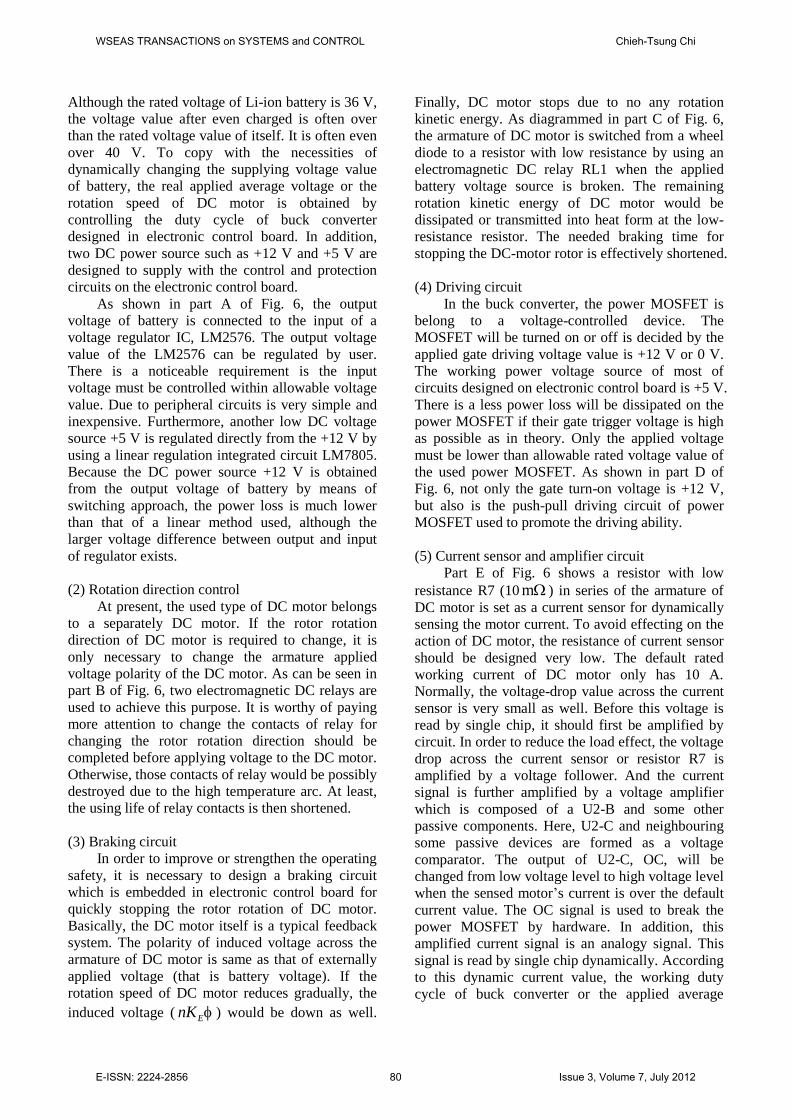
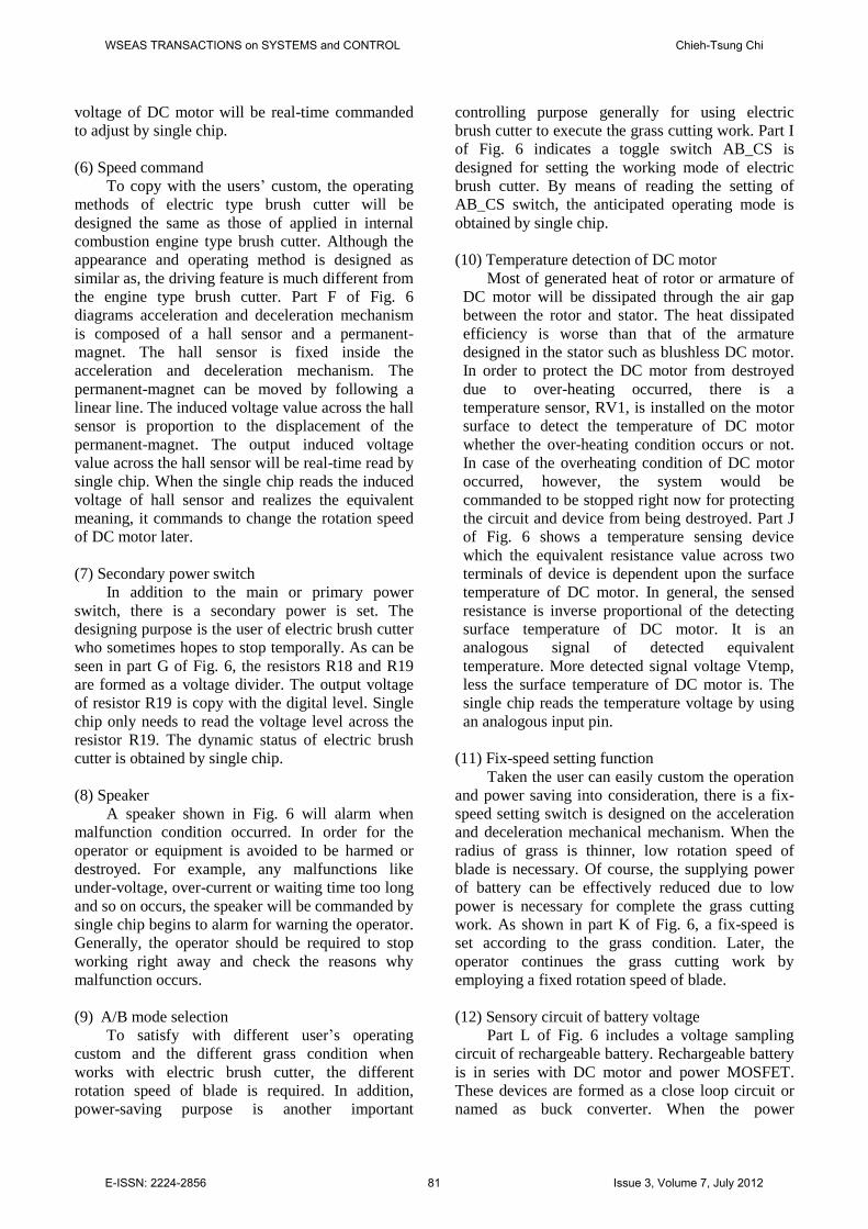
5.1 Implementation of prototypeGenerally speaking, the price of Li-ion is moreexpensive than the other types of rechargeablebattery. The total manufacturing cost of the electricbrush cutter is then increased. However, the cycliccharging and discharging times of Li-ion is superiorto other types of rechargeable battery within itsallowable using life. Therefore, the using cost whenthe Li-ion used is much lower than that ofconventional two or four strokes engine type brushcutter. In other words, the original increasing costfor buying the expensive electric brush cutter canfeedback very soon. Fig. 7(a) and (b) show theprototype pictures of electric brush cutter and theelectronic control board, respectively.
(a)
(b)Fig. 7. Completed prototype pictures (a) electric
brush cutter (b) electronic control board.
5.2 Operation process of single-chip softwareFig. 8 shows the operation process of the single chipdesigned in the electronic control board. The leftside of Fig. 8 is the initial self function testingprocess of the electric brush cutter. In case of theoutput voltage of the rechargeable battery is appliedto the electronic control board, the speaker first isalarmed three times, and then “PWR” indicatorlighted. The program will continue to detect thesecondary switch whether is turn off or not within
WSEAS TRANSACTIONS on SYSTEMS and CONTROL Chieh-Tsung Chi
E-ISSN: 2224-2856 82 Issue 3, Volume 7, July 2012
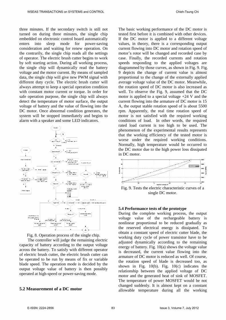
three minutes. If the secondary switch is still notturned on during three minutes, the single chipembedded on electronic control board automaticallyenters into sleep mode for power-savingconsideration and waiting for renew operation. Onthe contrarily, the single chip reads all the settingsof operator. The electric brush cutter begins to workby soft starting action. During all working process,the single chip will dynamically read the batteryvoltage and the motor current. By means of sampleddata, the single chip will give new PWM signal withdifferent duty cycle. The electric brush cutter willalways attempt to keep a special operation conditionwith constant motor current or torque. In order forsafe operation purpose, the single chip will alwaysdetect the temperature of motor surface, the outputvoltage of battery and the value of flowing into theDC motor. Once abnormal condition generates, thesystem will be stopped immediately and begins toalarm with a speaker and some LED indicators.
Fig. 8. Operation process of the single chip.The controller will judge the remaining electric
capacity of battery according to the output voltageacross the battery. To satisfy with different operatorof electric brush cutter, the electric brush cutter canbe operated to be run by means of fix or variableblade speed. The operation mode is decided by theoutput voltage value of battery is then possiblyoperated at high-speed or power-saving mode.
5.2 Measurement of a DC motor
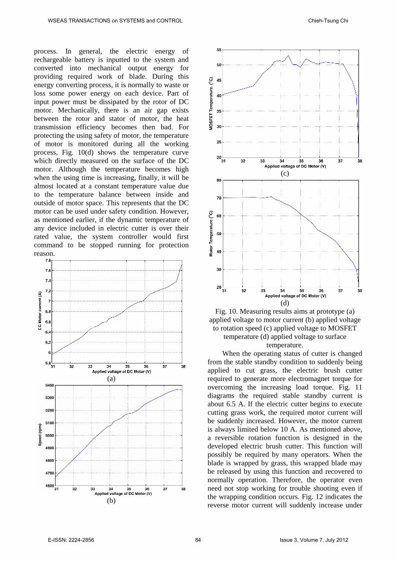
The basic working performance of the DC motor istested first before it is combined with other devices.If the DC motor is applied to a different voltagevalues, in theory, there is a corresponding outputcurrent flowing into DC motor and rotation speed ofmotor’s rotor will be changed and recorded case bycase. Finally, the recorded currents and rotationspeeds responding to the applied voltages arediagrammed by those curves, as shown in Fig. 9. Fig.9 depicts the change of current value is almostproportional to the change of the externally appliedaverage voltage value of the DC motor. Meanwhile,the rotation speed of DC motor is also increased aswell. To observe the Fig. 9, assumed that the DCmotor is applied to a special voltage +24 V and thecurrent flowing into the armature of DC motor is 15A, the output stable rotation speed of is about 5500rpm. Apparently, the real time rotation speed ofmotor is not satisfied with the required workingconditions of load. In other words, the requiredrated load current is too high to be used. Thephenomenon of the experimental results representsthat the working efficiency of the tested motor isworse under the required working conditions.Normally, high temperature would be occurred tothe DC motor due to the high power loss dissipatedin DC motor.
Fig. 9. Tests the electric characteristic curves of asingle DC motor.
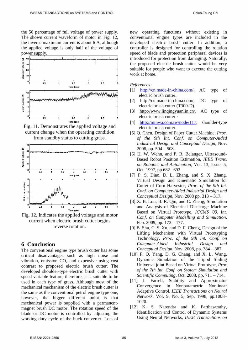
5.4 Performance tests of the prototypeDuring the complete working process, the outputvoltage value of the rechargeable battery isnonlinear proportional to be reduced gradually asthe reserved electrical energy is dissipated. Toobtain a constant speed of electric cutter blade, theworking duty cycle of power transistor have to beadjusted dynamically according to the remainingenergy of battery. Fig. 10(a) shows the voltage valueis decreased, the current value flowing into thearmature of DC motor is reduced as well. Of course,the rotation speed of blade is decreased too, asshown in Fig. 10(b). Fig. 10(c) indicates therelationship between the applied voltage of DCmotor and the generated heat of sink of MOSFET.The temperature of power MOSFET would be notchanged suddenly. It is almost kept on a constantallowable temperature during all the working
WSEAS TRANSACTIONS on SYSTEMS and CONTROL Chieh-Tsung Chi
E-ISSN: 2224-2856 83 Issue 3, Volume 7, July 2012
process. In general, the electric energy ofrechargeable battery is inputted to the system andconverted into mechanical output energy forproviding required work of blade. During thisenergy converting process, it is normally to waste orloss some power energy on each device. Part ofinput power must be dissipated by the rotor of DCmotor. Mechanically, there is an air gap existsbetween the rotor and stator of motor, the heattransmission efficiency becomes then bad. Forprotecting the using safety of motor, the temperatureof motor is monitored during all the workingprocess, Fig. 10(d) shows the temperature curvewhich directly measured on the surface of the DCmotor. Although the temperature becomes highwhen the using time is increasing, finally, it will bealmost located at a constant temperature value dueto the temperature balance between inside andoutside of motor space. This represents that the DCmotor can be used under safety condition. However,as mentioned earlier, if the dynamic temperature ofany device included in electric cutter is over theirrated value, the system controller would firstcommand to be stopped running for protectionreason.
(a)
(b)
(c)
(d)Fig. 10. Measuring results aims at prototype (a)
applied voltage to motor current (b) applied voltageto rotation speed (c) applied voltage to MOSFET
temperature (d) applied voltage to surfacetemperature.
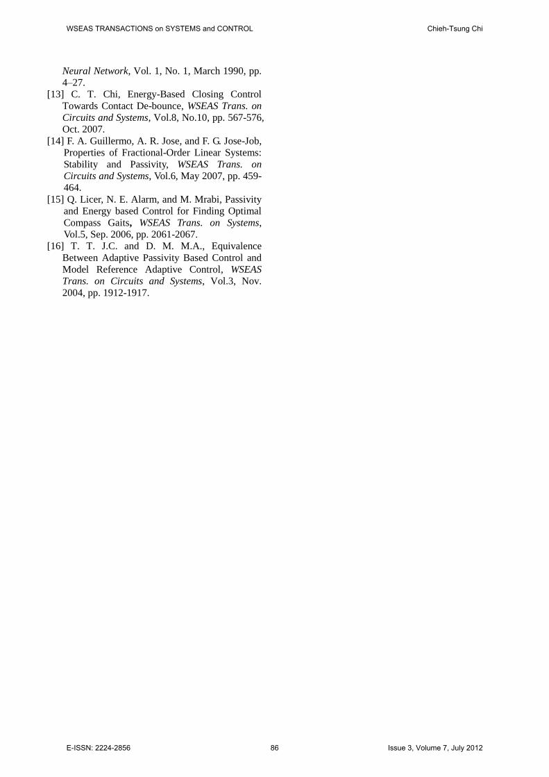
When the operating status of cutter is changedfrom the stable standby condition to suddenly beingapplied to cut grass, the electric brush cutterrequired to generate more electromagnet torque forovercoming the increasing load torque. Fig. 11diagrams the required stable standby current isabout 6.5 A. If the electric cutter begins to executecutting grass work, the required motor current willbe suddenly increased. However, the motor currentis always limited below 10 A. As mentioned above,a reversible rotation function is designed in thedeveloped electric brush cutter. This function willpossibly be required by many operators. When theblade is wrapped by grass, this wrapped blade maybe released by using this function and recovered tonormally operation. Therefore, the operator evenneed not stop working for trouble shooting even ifthe wrapping condition occurs. Fig. 12 indicates thereverse motor current will suddenly increase under
WSEAS TRANSACTIONS on SYSTEMS and CONTROL Chieh-Tsung Chi
E-ISSN: 2224-2856 84 Issue 3, Volume 7, July 2012
the 50 percentage of full voltage of power supply.The shown current waveform of motor in Fig. 12,the inverse maximum current is about 6 A, althoughthe applied voltage is only half of the voltage ofpower supply.
Fig. 11. Demonstrates the applied voltage andcurrent change when the operating condition
from standby status to cutting grass.
Fig. 12. Indicates the applied voltage and motorcurrent when electric brush cutter begins
reverse rotation.
6 ConclusionThe conventional engine type brush cutter has somecritical disadvantages such as high noise andvibration, emission CO2 and expensive using costcontrast to proposed electric brush cutter. Thedeveloped shoulder-type electric brush cutter withspeed variable feature, therefore, it is suitable to beused in each type of grass. Although most of themechanical mechanism of the electric brush cutter isthe same as the conventional petrol engine type one,however, the bigger different point is thatmechanical power is supplied with a permanent-magnet brush DC motor. The rotation speed of theblade or DC motor is controlled by adjusting theworking duty cycle of the buck converter. Lots of
new operating functions without existing inconventional engine types are included in thedeveloped electric brush cutter. In addition, acontroller is designed for controlling the rotationspeed of blade and protection peripheral devices isintroduced for protection from damaging. Naturally,the proposed electric brush cutter would be verysuitable for people who want to execute the cuttingwork at home.
References:[1] http://cn.made-in-china.com/, AC type of
electric brush cutter.[2] http://cn.made-in-china.com/, DC type of
electric brush cutter (T300-D).[3] http://www.linqingyuanlin.cn/, AC type of
electric brush cutter。[4] http://minwa.com.tw/node/117, shoulder-type
electric brush cutter.[5] Q. Chen, Design of Paper Cutter Machine, Proc.
of the 9th Int. Conf. on Computer-AidedIndustrial Design and Conceptual Design, Nov.2008, pp. 504 –508.
[6] H. W. Wehn, and P. R. Belanger, Ultrasound-Based Robot Position Estimation, IEEE Trans.on Robotics and Automation, Vol. 13, Issue: 5,Oct. 1997, pp.682 –692.
[7] P. S. Diao, D. L. Zhang, and S. X. Zhang,Virtual Design and Kinematic Simulation forCutter of Corn Harvester, Proc. of the 9th Int.Conf. on Computer-Aided Industrial Design andConceptual Design, Nov. 2008 pp. 313 –317.
[8] X. B. Lou, B. R. Qin, and C. Zheng, Simulationand Analysis of Electrical Discharge MachineBased on Virtual Prototype, ICCMS '09. Int.Conf. on Computer Modelling and Simulation,Feb. 2009, pp. 173 –177.
[9] B. Shu, C. S. Xu, and D. F. Cheng, Design of theLifting Mechanism with Virtual PrototypingTechnology, Proc. of the 9th Int. Conf. onComputer-Aided Industrial Design andConceptual Design, Nov. 2008, pp. 384 –387.
[10] F. Q. Yang, D. G. Chang, and X. L. Wang,Dynamic Simulation of the Tripod SlidingUniversal joint Based on Virtual Prototype, Proc.of the 7th Int. Conf. on System Simulation andScientific Computing, Oct. 2008, pp. 711 –714.
[11] J. Farrell, Stability and ApproximatorConvergence in Nonparametric NonlinearAdaptive Control, IEEE Transactions on NeuralNetwork, Vol. 9, No. 5, Sep. 1998, pp.1008–1020.
[12] K. S. Narendra and K. Parthasarathy,Identification and Control of Dynamic SystemsUsing Neural Networks, IEEE Transactions on
WSEAS TRANSACTIONS on SYSTEMS and CONTROL Chieh-Tsung Chi
E-ISSN: 2224-2856 85 Issue 3, Volume 7, July 2012
Neural Network, Vol. 1, No. 1, March 1990, pp.4–27.
[13] C. T. Chi, Energy-Based Closing ControlTowards Contact De-bounce, WSEAS Trans. onCircuits and Systems, Vol.8, No.10, pp. 567-576,Oct. 2007.
[14] F. A. Guillermo, A. R. Jose, and F. G. Jose-Job,Properties of Fractional-Order Linear Systems:Stability and Passivity, WSEAS Trans. onCircuits and Systems, Vol.6, May 2007, pp. 459-464.
[15] Q. Licer, N. E. Alarm, and M. Mrabi, Passivityand Energy based Control for Finding OptimalCompass Gaits, WSEAS Trans. on Systems,Vol.5, Sep. 2006, pp. 2061-2067.
[16] T. T. J.C. and D. M. M.A., EquivalenceBetween Adaptive Passivity Based Control andModel Reference Adaptive Control, WSEASTrans. on Circuits and Systems, Vol.3, Nov.2004, pp. 1912-1917.
WSEAS TRANSACTIONS on SYSTEMS and CONTROL Chieh-Tsung Chi
E-ISSN: 2224-2856 86 Issue 3, Volume 7, July 2012