
A New Design of Dual-Port Active Integrated Antenna for 2...
12
Progress In Electromagnetics Research B, Vol. 58, 83–94, 2014 A New Design of Dual-Port Active Integrated Antenna for 2.4/5.2 GHz WLAN Applications Arash Valizade * , Pejman Rezaei, and Ali A. Orouji Abstract—A new design of dual-port monopole-slot-like microstrip active integrated antenna (AIA) is presented and discussed in this paper. The primary designed passive antenna is capable of supporting two different WLAN bands at 2.4–2.84 GHz and 5.15–5.35 GHz due to its dual-port structure. In order to reduce the transmission coefficient between the two ports of antenna a coupling sleeve-arm and an inverted T-shaped slot are utilized on the ground plane of antenna each beneath one of the corresponding feed-lines which act as filtering structures at desirable frequencies. The proposed passive dual-port antenna is integrated with a power amplifier (PA) and a low noise amplifier forming a dual- port microstrip AIA which can be used as a full-duplex transceiver at its operating WLAN frequency bands. The measured results for both passive and active antennas show that the designed antennas have proper radiation characteristics at their desired operation frequencies. The fabricated passive antenna exhibits dual-band performance at 2–3.42 GHz and 4.5–5.6 GHz while the fabricated AIA covers 2.31– 2.82 GHz (at PA port) and 4.45–5.5 GHz (at LNA Port) with 13 dB and 9 dB gain level improvement respectively. 1. INTRODUCTION In recent years, the active integrated antenna (AIA) aspect has become a growing and developing research area which has absorbed a lot of attention toward itself. In one definition the AIA can be considered as an active microwave circuit which its input or output is terminated in free space rather than the conventional 50 Ω terminations. The active device in an AIA can be of any kind such as transistors (three-terminal device) or Gunn diodes (two-terminal device), and any planar antennas such as microstrip patch or microstrip slot antennas can be used as the radiating element [1–3]. The microstrip antennas are a good candidate for integration with active components and forming AIAs because of their small size, light weight, low price, and ease of fabrication and integration [4,5]. Apart from its basic role which is radiation, the antenna component in an AIA circuit can offer additional performances such as filtering, resonating, duplexing and etc.. Various active integrated antennas based on different configuration of the antenna or different combination of the radiator element with amplifiers, mixers, and oscillators have been presented in the literature [6–16]. Moreover, some of them have been proposed as transmitter-receiver (transceiver) units [17]. The key issue in the design of the active integrated transceivers is that the isolation between the transmitter and receiver ports must be maintained. The Isolation can be achieved by an auxiliary circuit, or instead of using an external additional component the isolation between ports can be produced by using the inherent properties of microstrip antennas [18, 19]. In [14] an AIA with two separate radiating elements for full duplex operation is presented. Each radiating element of the proposed antenna in [18] has its individual amplifier stage and so it can transmit and receive the signal simultaneously. In [19] an integrated active circulator antenna is proposed in which Gunn diodes are used as amplifiers and isolating elements Received 24 October 2013, Accepted 9 January 2014, Scheduled 20 January 2014 * Corresponding author: Arash Valizade ([email protected]). The authors are with the Department of Electrical Engineering, Semnan University, Semnan, Iran.
Transcript of A New Design of Dual-Port Active Integrated Antenna for 2...

Progress In Electromagnetics Research B, Vol. 58, 83–94, 2014
A New Design of Dual-Port Active Integrated Antenna for2.4/5.2GHz WLAN Applications
Arash Valizade*, Pejman Rezaei, and Ali A. Orouji
Abstract—A new design of dual-port monopole-slot-like microstrip active integrated antenna (AIA) ispresented and discussed in this paper. The primary designed passive antenna is capable of supportingtwo different WLAN bands at 2.4–2.84 GHz and 5.15–5.35 GHz due to its dual-port structure. Inorder to reduce the transmission coefficient between the two ports of antenna a coupling sleeve-armand an inverted T-shaped slot are utilized on the ground plane of antenna each beneath one of thecorresponding feed-lines which act as filtering structures at desirable frequencies. The proposed passivedual-port antenna is integrated with a power amplifier (PA) and a low noise amplifier forming a dual-port microstrip AIA which can be used as a full-duplex transceiver at its operating WLAN frequencybands. The measured results for both passive and active antennas show that the designed antennas haveproper radiation characteristics at their desired operation frequencies. The fabricated passive antennaexhibits dual-band performance at 2–3.42GHz and 4.5–5.6 GHz while the fabricated AIA covers 2.31–2.82GHz (at PA port) and 4.45–5.5GHz (at LNA Port) with 13 dB and 9 dB gain level improvementrespectively.
1. INTRODUCTION
In recent years, the active integrated antenna (AIA) aspect has become a growing and developingresearch area which has absorbed a lot of attention toward itself. In one definition the AIA can beconsidered as an active microwave circuit which its input or output is terminated in free space ratherthan the conventional 50 Ω terminations. The active device in an AIA can be of any kind such astransistors (three-terminal device) or Gunn diodes (two-terminal device), and any planar antennassuch as microstrip patch or microstrip slot antennas can be used as the radiating element [1–3]. Themicrostrip antennas are a good candidate for integration with active components and forming AIAsbecause of their small size, light weight, low price, and ease of fabrication and integration [4, 5]. Apartfrom its basic role which is radiation, the antenna component in an AIA circuit can offer additionalperformances such as filtering, resonating, duplexing and etc.. Various active integrated antennasbased on different configuration of the antenna or different combination of the radiator element withamplifiers, mixers, and oscillators have been presented in the literature [6–16]. Moreover, some of themhave been proposed as transmitter-receiver (transceiver) units [17]. The key issue in the design of theactive integrated transceivers is that the isolation between the transmitter and receiver ports mustbe maintained. The Isolation can be achieved by an auxiliary circuit, or instead of using an externaladditional component the isolation between ports can be produced by using the inherent propertiesof microstrip antennas [18, 19]. In [14] an AIA with two separate radiating elements for full duplexoperation is presented. Each radiating element of the proposed antenna in [18] has its individualamplifier stage and so it can transmit and receive the signal simultaneously. In [19] an integrated activecirculator antenna is proposed in which Gunn diodes are used as amplifiers and isolating elements
Received 24 October 2013, Accepted 9 January 2014, Scheduled 20 January 2014* Corresponding author: Arash Valizade ([email protected]).The authors are with the Department of Electrical Engineering, Semnan University, Semnan, Iran.

84 Valizade, Rezaei, and Orouji
concurrently. The proposed structure is mentioned as an active circulator and is able to work as atransceiver with proper isolation between its transmitter and receiver ports.
In this paper, an AIA with a dual-port monopole-slot-like microstrip antenna is presented and itsdifferent characteristics are discussed. The proposed dual-port antenna is capable of supporting twoseparate frequency bands and each of its ports corresponds to one of these frequency bands. Unlike theantenna presented in [19] that has two radiating elements (a square ring radiator and an inset-fed patchradiator) which are combined to form a single radiating element, the presented antenna in this paperutilizes just a single rectangular patch section to be used as the radiating element. Due to the fact thatboth ports of the proposed antenna are connected directly to the radiating patch, the isolation betweenthese ports is too poor. So in order to improve the isolation between ports, the antenna structure ismodified and by using a coupling sleeve-arm under one of the feed-lines and also by cutting an invertedT-shaped slot on the ground plane beneath the other feed-line, proper isolation between antenna portsis obtained. In a short comparison with the AIAs presented in [18, 19], the AIA presented in this paperhas a single radiating element and it produces the isolation between its ports passively rather thanutilizing an active circulator antenna. The antenna section in the proposed AIA structure does work asthe radiating element and isolating component concurrently and it filters unwanted frequency bands atits ports without any increase in size or cost. The following sections deal with the antenna geometry,design theory, simulation and experimental results.
2. PASSIVE DUAL-PORT ANTENNA DESIGN AND CONFIGURATION
The proposed dual-port monopole-slot-like microstrip passive antenna configuration with its designparameters is shown in Figure 1 and its final modified design parameters values are presented inTable 1. The simulated results are obtained using Ansoft Simulation Software High Frequency Structure
(a)
(b) (c)
Figure 1. The Geometry of the proposed passive dual-port antenna: (a) side view, (b) bottom view,(c) top view.

Progress In Electromagnetics Research B, Vol. 58, 2014 85
Table 1. Design parameters of the proposed passive dual-port antenna.
Param. mm Param. mm Param. mm Param. mm Param. mmWSub 48.5 WP 12.5 LF1 12.5 LP1 11.45 W1 1.5LSub 33 LP 26 LF2 10.5 WP1 14.69 W2 2.5W3 14 W4 3 LG1 9.5 LG2 6 L1 6L2 3 L3 1 L4 10 L5 4.125 L6 1
Simulator (HFSS) [20]. The presented antenna is printed on a FR4 substrate with thickness of 1.6 mm,permittivity of 4.4, and loss tangent of 0.018. As it can be observed in Figure 1, the basic antennastructure consists of a simple rectangular radiating patch, two microstrip feed-lines which are connectedorthogonally to the radiating patch, and a L-shaped defected ground plane.
The radiating patch is designed and its dimensions are modified so to be able to cover two frequencybands at 2.4–2.84 GHz (WLAN) and 5.15–5.35 (WLAN) GHz. In order to be capable of being used as atransceiver element, each of the microstrip feed-lines which are connected to the radiating patch shouldtransfer just one of these frequency bands but since they are connected directly to the radiating patch,the isolation between the corresponding termination ports is poor. Consequently at the next step ofthe design procedure the attention was focused on the isolation between the ports. Instead of using anyactive or passive additional circuits or components at each port of the antenna, the inherent properties ofthe microstrip antennas were used to improve the isolation [18, 19, 21]. By adding a modified sleeve-armto the ground plane under one of the feed-lines (see Figure 1(b)) and by controlling the coupling betweenthis sleeve-arm and the feed-line which is placed above the arm, the unwanted frequency band at thecorresponding port (Port 1 in Figure 1(a)) can be filtered [22]. Also by cutting an inverted T-shapedslot in which an inverted T-shaped stub is protruded, on the ground plane, an additional current pathon the ground plane right beneath the other feed-line is created (Port 2 in Figure 1(a)). Through fineadjustment of the coupling between the protruded inverted T-shaped stub and the feed-line which isplaced above it, the unwanted frequency band at the corresponding port (Port 2 in Figure 1(a)) canbe suppressed [5, 21, 22]. The simulated frequency response for the proposed antenna in Figure 1 isshown in Figure 2. As it is observed in this figure, port 1 supports the frequency band of 4.65–5.7GHzwhile port 2 covers the frequency band of 2–3GHz. Also, as it is depicted in Figure 2, the transmissionbetween the two ports of the antenna is satisfactorily low, especially at the operating frequency bands.
Figure 2. The simulated frequency response of the proposed passive dual-port antenna.
Various dual-port antenna structures which were investigated in simulation studies are depicted inFigure 3, and their frequency responses are compared in Figure 4, Figure 5, and Figure 6. The returnloss characteristics of these various antennas at Port 1 are compared in Figure 4. As it is observed inthis figure, for all the four configurations, the antenna can support the frequency band at frequenciesapproximately between 4.6–5.7 GHz through Port 1. Moreover, the return loss characteristics of thesevarious antennas at Port 2 are compared in Figure 5. As it is observed in this figure, again for all the fourconfigurations, the antenna can support the frequency band at frequencies approximately between 2–
86 Valizade, Rezaei, and Orouji
(a) (b)
(c) (d)
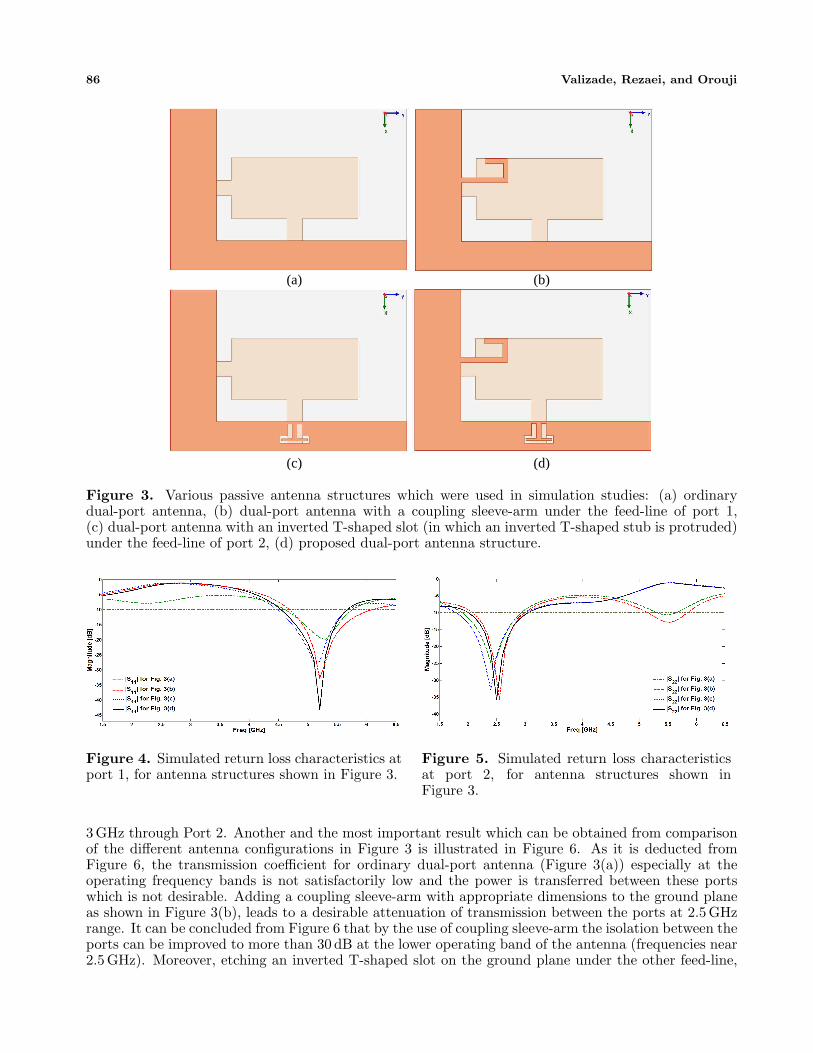
Figure 3. Various passive antenna structures which were used in simulation studies: (a) ordinarydual-port antenna, (b) dual-port antenna with a coupling sleeve-arm under the feed-line of port 1,(c) dual-port antenna with an inverted T-shaped slot (in which an inverted T-shaped stub is protruded)under the feed-line of port 2, (d) proposed dual-port antenna structure.
Figure 4. Simulated return loss characteristics atport 1, for antenna structures shown in Figure 3.
Figure 5. Simulated return loss characteristicsat port 2, for antenna structures shown inFigure 3.
3GHz through Port 2. Another and the most important result which can be obtained from comparisonof the different antenna configurations in Figure 3 is illustrated in Figure 6. As it is deducted fromFigure 6, the transmission coefficient for ordinary dual-port antenna (Figure 3(a)) especially at theoperating frequency bands is not satisfactorily low and the power is transferred between these portswhich is not desirable. Adding a coupling sleeve-arm with appropriate dimensions to the ground planeas shown in Figure 3(b), leads to a desirable attenuation of transmission between the ports at 2.5 GHzrange. It can be concluded from Figure 6 that by the use of coupling sleeve-arm the isolation between theports can be improved to more than 30 dB at the lower operating band of the antenna (frequencies near2.5GHz). Moreover, etching an inverted T-shaped slot on the ground plane under the other feed-line,

Progress In Electromagnetics Research B, Vol. 58, 2014 87
Figure 6. Simulated transmission characteristics between port 1 and port 2, for antenna structuresshown in Figure 3.
as shown in Figure 3(c), results in a desirable attenuation of transmission between two ports at 5.2 GHz.As it is depicted in Figure 6, by cutting an inverted T-shaped slot in which an inverted T-shaped stub isprotruded, on the ground plane, the isolation between dual-ports can be improved to more than 20 dB atthe higher operating band of the antenna (frequencies near 5.2 GHz). Finally, for the presented antennastructure in this paper which is shown in Figure 3(d), the corresponding frequency response in Figure 6implies that in the proposed antenna structure proper isolation between two ports at both operatingfrequency bands is achieved.
In order to give a more clear insight about the phenomenon of the isolation improvement whichoccurs at the operating frequency bands for the proposed passive antenna structure, the surface currentdistribution on the ground plane is depicted in Figure 7. As it is shown in Figure 7(a), at the loweroperating frequency band (2.4 GHz) the current flows on the ground plane are more dominant andconcentrated along the coupling sleeve-arm. In other words, embedding a sleeve-arm which is connectedto the ground plane creates an additional current path that is coupled to the feed-line which is placedabove it. Based on electromagnetic coupling theory (ECT) by properly adjusting the dimensions ofthe sleeve-arm for a certain desired frequency it can be coupled to the feed-line above it with oppositecurrent and field direction which cancels the total field distribution on the feed-line for that specificfrequency band. Since the port 2 (see Figure 1) is assigned to operate at 2.5 GHz range, the dimensionsof the coupling sleeve-arm at port 1 is modified to filter this frequency range and suppress the signaltransmission from port 2 to port 1 [18]. The current distribution on ground plane at the higher operatingfrequency band (5.2 GHz) is shown in Figure 7(b). As it is shown in this figure at higher operatingfrequency band the current distribution is more dominant and concentrated around the inverted T-shaped slot and its inner inverted T-shaped stub. The slot on the ground plane creates an additionalcurrent path and by adjusting the dimensions of the slot and its inner stub, the coupling between the
(a) (b)
Figure 7. Simulated surface current distribution on the ground plane at: (a) 2.5 GHz, (b) 5.2 GHz.

88 Valizade, Rezaei, and Orouji
mentioned structure and the microstrip feed-line above it can be tuned and controlled. In fact theinverted T-shaped stub works as a half wavelength resonator at 5.2 GHz and creates an additional fieldwhich cancels the field distribution on the feed-line above it at this frequency range. The couplingbetween the microstrip feed-line and slotted resonator on the ground plane is mainly decided by theshape and critical dimensions of the slot and its inner stub [5, 21]. The relationship between dimensionsand the resonance frequency is investigated by EM simulation. Since the port 1 (see Figure 1) is assignedto operate at 5.2 GHz range, the dimensions of the slot and the inverted T-shaped stub at port 2 ismodified to filter this frequency range and suppress the signal transmission from port 1 to port 2.
3. DUAL-PORT AIA DESIGN AND CONFIGURATION
The proposed passive dual-port antenna in previous section is combined with a low noise amplifier anda power amplifier at its ports and forms an active integrated dual-port antenna which can be used as afull-duplex transceiver for WLAN applications. In this section the configuration and operation of theproposed active antenna is presented and discussed. A schematic diagram of the proposed dual-portactive integrated antenna is shown in Figure 8. As it is observed in this figure, port 1 of the antennastructure in Figure 1 is connected to a low noise amplifier (LNA) as its feeding point and the port 2 of theantenna structure in Figure 1 is connected to a power amplifier (PA) as its output load. The LNA andPA are designed and their input and outputs are matched to work at 5.2GHz and 2.5 GHz respectively.The dual-port antenna structure which is integrated with the mentioned LNA and PA, works as bothradiating element and isolating element concurrently and omits the need for any additional filteringcomponents.
Figure 8. Schematic diagram of the proposed dual-port AIA.
The structure of the designed LNA and PA is illustrated in Figure 9. Both designed amplifiersobey from this structure but their design parameters values differ according to their specific operatingfrequency bands. The amplifiers are designed and modified with Agilent ADS software [23]. The utilizedactive device in both designed amplifiers is ATF36077 and the resistor (R) in the amplifiers structureis used for stability considerations. The final modified values of the design parameters for the LNA andPA are listed in Table 2.
Figure 10 and Figure 11 show the frequency responses of the designed LNA and PA respectively.As it is deducted from Figure 10, the design parameters of the LNA are modified to have matchingconditions for its input and output ports at 5.2 GHz, while the design parameters of the PA are modifiedfor matching conditions at 2.5 GHz, as can be concluded from Figure 11. The simulation results indicatethat both LNA and PA are properly designed for their specific operation frequency bands.
Table 2. Design parameters of the proposed amplifiers.
Amplifier L1 L2 L3 L4 L5 L6 L7 R ()Low Noise Amp. 1 mm 2.5mm 5 mm 2mm 1 mm 6.3 mm 14.2 mm 27 Ω
Power Amp. 1mm 5.4 mm 3.12mm 2 mm 1 mm 12.7 mm 6.7 mm 33Ω

Progress In Electromagnetics Research B, Vol. 58, 2014 89
Figure 9. Structure of the designed LNA and PA.
Figure 10. Simulated frequency response of thedesigned LNA.
Figure 11. Simulated frequency response of thedesigned PA.
4. RESULTS AND DISCUSSIONS
A prototype of the proposed passive dual-port monopole-slot-like microstrip antenna and a prototype ofthe corresponding proposed active integrated antenna with their final modified parameters is designed,fabricated and tested and in this section the experimental results of their bandwidth and radiationcharacteristics are presented and discussed. The picture of the fabricated passive antenna is shownin Figure 12 and its measured frequency response is presented in Figure 13. As it is depicted inFigure 13, the realized passive antenna can cover two distinct frequency bands with respect to its dual-port configuration. According to ports nomination in Figure 12 the measured results reveal that thepassive antenna covers the upper operation frequency band (4.5–5.6GHz) through port 1, and alsoit covers the lower operation frequency band (2–3.42 GHz) through port 2. Both operating frequencybands are a portion of the WLAN spectrum and so the fabricated passive antenna can be used in WLANapplications. Another important result which can be concluded from Figure 13 is that as it was predictedin simulation studies there exists a suitable isolation between ports especially at the operating frequencybands which means that the power transmission between ports (|S21| level) is low. The performance ofthe proposed antenna is enhanced without any increase of size or expenses but just through using theinherent properties of the microstrip antenna and in fact the antenna in addition to its main role whichis radiation has an additional desired performance as a filter which omits the need of using filtering

90 Valizade, Rezaei, and Orouji
(a) (b)
Figure 12. Photograph of the fabricated passive dual-port antenna.
Figure 13. Measured frequency response of the fabricated passive dual-port antenna.
components between ports. Implementation of a coupling sleeve-arm under the feed-line of port 1 leadsto transmission suppression at 2–4 GHz while etching an inverted T-shaped slot in which an InvertedT-shaped stub is protruded, on the ground plane under the feed-line of port 2, causes transmissionsuppression at 4.7–5.5 GHz, as predicted in simulation studies. The measured experimental results forrealized passive antenna are in fine agreement with simulation data.
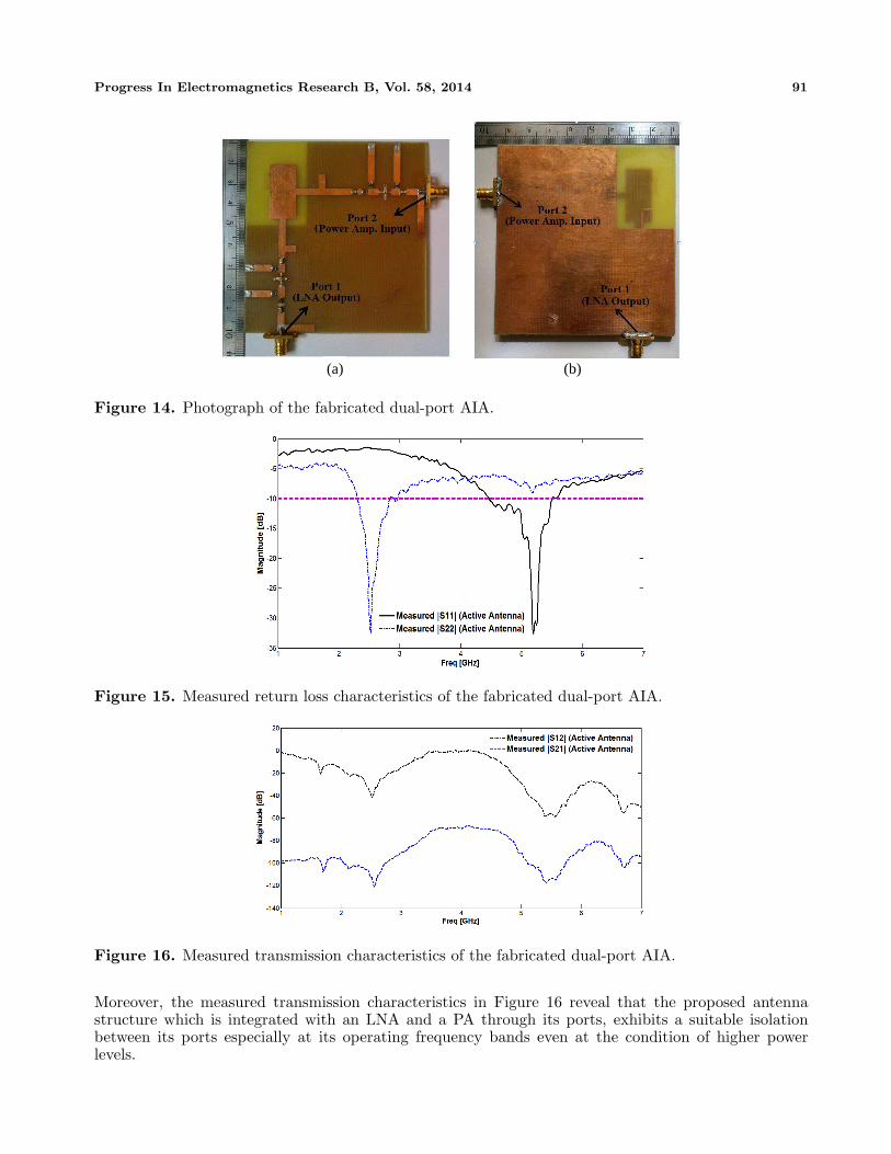
In order to test the performance of the proposed active integrated antenna which is designed basedon the structure of the proposed enhanced passive dual-port antenna, under real conditions, a prototypeof the designed AIA is fabricated and its operation is investigated. The picture of the fabricated activeintegrated dual-port antenna is shown in Figure 14. According to the ports nomination in Figure 14 thePort 1 is the output of a 5.2 GHz LNA which its input is excited through port 1 of the proposed passiveantenna (see Figure 12), while port 2 in Figure 14 is the input of a 2.5 GHz PA which its output isloaded with the proposed passive antenna thorough its port 2 (see Figure 12). Measured return loss andtransmission characteristics of the realized AIA are depicted in Figure 15 and Figure 16 respectively.The fabricated AIA covers two distinct frequency bands at 2.31–2.82 GHz and 4.45–5.5GHz which bothare portions of the WLAN spectrum and reveal that the presented dual-port AIA can be used as afull-duplex transceiver for WLAN applications. The covered frequency bands for the AIA in Figure 15are narrower in contrast with the covered bands of the passive antenna which is due to the fact thatthe designed LNA and PA are narrowband amplifiers and reduce the total bandwidth of the system,nevertheless the AIA bandwidths satisfactorily supports the mentioned WLAN bands and even more.
Progress In Electromagnetics Research B, Vol. 58, 2014 91
(a) (b)
Figure 14. Photograph of the fabricated dual-port AIA.
Figure 15. Measured return loss characteristics of the fabricated dual-port AIA.
Figure 16. Measured transmission characteristics of the fabricated dual-port AIA.
Moreover, the measured transmission characteristics in Figure 16 reveal that the proposed antennastructure which is integrated with an LNA and a PA through its ports, exhibits a suitable isolationbetween its ports especially at its operating frequency bands even at the condition of higher powerlevels.
92 Valizade, Rezaei, and Orouji
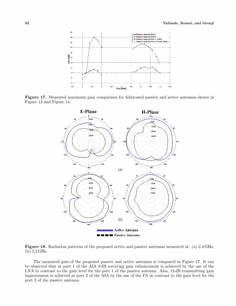
Figure 17. Measured maximum gain comparison for fabricated passive and active antennas shown inFigure 12 and Figure 14.
(a)
(b)
Figure 18. Radiation patterns of the proposed active and passive antennas measured at: (a) 2.4 GHz,(b) 5.2 GHz.
The measured gain of the proposed passive and active antennas is compared in Figure 17. It canbe observed that at port 1 of the AIA 9 dB receiving gain enhancement is achieved by the use of theLNA in contrast to the gain level for the port 1 of the passive antenna. Also, 13 dB transmitting gainimprovement is achieved at port 2 of the AIA by the use of the PA in contrast to the gain level for theport 2 of the passive antenna.

Progress In Electromagnetics Research B, Vol. 58, 2014 93
The measured E-plane and H-plane radiation patterns of the fabricated active and passive antennasare depicted in Figure 18. The patterns are normalized to the gain in the maximum radiating directionof the passive antenna at each operation frequencies, and as it can be observed in Figure 18 the radiationpatterns of the active antenna are distorted which is attributed to radiation from the amplifier circuits.The pattern distortion can be decreased by providing shielding or other provisions.
5. CONCLUSION
In this paper, a new design of dual-port monopole-slot-like microstrip active integrated antenna isproposed for WLAN applications. The fabricated passive antenna has two distinct operating frequencybands at 2–3.42GHz and 4.5–5.6GHz due to its dual-port configuration, and improved gain levels isobtained by utilizing amplifiers at its ports. A low noise amplifier and a power amplifier are designedand integrated with the proposed antenna structure forming a full-duplex transceiver. The experimentalresults for the proposed AIA reveal that it covers frequency bands of 2.31–2.82 GHz and 4.45–5.5 GHzwith 13 dB and 9 dB gain enhancement respectively in contrast to the fabricated passive antenna.The antenna element in addition to its basic duty which is working as the radiating element hasbeen enhanced to create suitable isolation between its ports and works as the filtering componentsconcurrently. The measured and simulated results for both proposed passive and active antennas arein appropriate correlation and agreement, and the presented antenna can be used as a full-duplextransceiver for WLAN applications.
ACKNOWLEDGMENT
The authors are thankful to Microwave Technology (MWT) Company staff for their beneficial andprofessional help (www.microwave-technology.com).
REFERENCES
1. Ibrahim, S. H., “Design and analysis considerations of 4 GHz integrated antenna with negativeresistance oscillator,” Progress In Electromagnetics Research B, Vol. 13, 111–131, 2009.
2. Chang, K., R. A. York, P. S. Hall, and T. Itoh, “Active integrated antennas,” IEEE Transactionson Antennas and Wireless Propagation, Vol. 50, No. 3, 937–944, 2002.
3. Bilotti, F., F. Urbani, and L. Vegni, “Design of active integrated antenna for a PCMCIA card,”Progress In Electromagnetics Research, Vol. 61, 253–270, 2006.
4. Kumar, G. and K. P. Ray, Broadband Microstrip Antennas, Artech House, Antennas andPropagations Library, 2003.
5. Valizade, A., C. Ghobadi, J. Nourinia, N. Ojaroudi, and M. Ojaroudi, “Band-notch slot antennawith enhanced bandwidth by using Ω-shaped strips protruded inside rectangular slots for UWBapplications,” Applied Computational Electromagnetics Society (ACES) Journal, Vol. 27, No. 10,816–822, 2012.
6. Kaya, A., “High gain rectangular broad band microstrip antenna with embedded negative capacitorand chip resistors,” Progress In Electromagnetics Research, Vol. 78, 421–436, 2008.
7. Yun, G. H., “Compact oscillator-type active antenna for UHF RFID reader,” Electronics Letters,Vol. 43, No. 6, 314–315, 2007.
8. Lin, Y. Y. and T. G. Ma, “Frequency-reconfigurable self-oscillating active antenna with gap-loadedring radiator,” IEEE Antennas and Propagation Letters, Vol. 12, 337–340, 2013.
9. Bonefacic, D., J. Baartolic, and Z. Mustic, “Circular active integrated antenna with push-pulloscillator,” Electronics Letters, Vol. 38, No. 21, 1238–1240, Oct. 2002.
10. Kurup, D. G., A. Rydberg, and M. Himdi, “Compact microstrip T-coupled patch antenna for dualpolarisation and active antenna applications,” Electronics Letters, Vol. 38, No. 21, 1240–1241, 2002.
11. Lee, J., C. T. M. Wu, and T. Itoh, “A power efficient active integrated antenna,” Microwave andOpt. Technol. Letters, Vol. 55, No. 6, 1240–1243, 2013.

94 Valizade, Rezaei, and Orouji
12. Lin, Y. Y., C. H. Wu, and T. G. Ma, “Minituarized self-oscillating annular ring active integratedantennas,” IEEE Transactions on Antennas and Wireless Propagation, Vol. 59, No. 10, 3597–3606,2011.
13. Giuppi, F., A. Georgiadis, A. Collado, M. Bozzi, and L. Perregrini, “Tunable SIW cavity backedactive antenna oscillator,” Electronics Letters, Vol. 46, No. 15, 1053–1055, 2010.
14. Wu, C.-H. and T.-G. Ma, “Self-oscillating dual-ring active integrated antenna,” IEEE Int. Symp.Antennas and Propagation Symp. Digest, 2457–2460, Spokane, WA, 2011.
15. Choi, D. H. and S. O. Park, “Active integrated antenna using a T-shaped microstrip coupled patchantenna,” Microwave and Opt. Technol. Letters, Vol. 44, No. 5, 434436, 2004
16. Choi, D. H. and S. O. Park, “A frequency agile active microstrip antenna for CP Operation,”Microwave and Opt. Technol. Letters, Vol. 54, No. 9, 2205–2209, 2012.
17. Flynt, R., L. Fan, J. Navarro, and K. Chang, “Low cost and compact active integrated antennatransceiver for system applications,” IEEE Transactions on Microwave Theory and Techniques,Vol. 44, No. 10, 1642–1649, 1996.
18. Cryan, M. J., P. S. Hall, S. H. Tsang, and J. Sha, “Integrated active antenna with full duplexoperation,” IEEE Transactions on Antennas and Wireless Propagation, Vol. 45, No. 10, 1742–1748, 1997.
19. Kalialakis, C., M. J. Cryan, P. S. Hall, and P. Gardner, “Analysis and design of integrated activecirculator antennas,” IEEE Transactions on Antennas and Wireless Propagation, Vol. 48, No. 6,1017–1023, 2000.
20. Ansoft High Frequency Structure Simulator (HFSS), Ver. 13, Ansoft Corporation, 2010.21. Valizade, A., C. Ghobadi, J. Nourinia, and M. Ojaroudi, “A novel design of reconfigurable slot
antenna with switchable band notch and multi-resonance functions for UWB applications,” IEEEAntenna and Wireless Propagation Letters, Vol. 11, 1166–1169, 2012.
22. Ojaroudi, M., N. Ojaroudi, and N. Ghadimi, “A novel design of dual band-notched slotantenna using a pair of Γ-shaped protruded strips for UWB applications,” Applied ComputationalElectromagnetics Society (ACES) Journal, Vol. 28, No. 4, 816–822, 2013.
23. Advanced Design System (ADS), Agilent Corporation, 2009.


