A neuro-fuzzy controller for grid-connected heavy-duty gas...
13
Turk J Elec Eng & Comp Sci (2017) 25: 2375 – 2387 c ⃝ T ¨ UB ˙ ITAK doi:10.3906/elk-1511-242 Turkish Journal of Electrical Engineering & Computer Sciences http://journals.tubitak.gov.tr/elektrik/ Research Article A neuro-fuzzy controller for grid-connected heavy-duty gas turbine power plants Mohamed Mustafa MOHAMED IQBAL 1, * , Rayappan JOSEPH XAVIER 1 , Jagannathan KANAKARAJ 2 1 Department of Electrical & Electronics Engineering, Sri Ramakrishna Institute of Technology, Coimbatore, Tamil Nadu, India 2 Department of Electrical & Electronics Engineering, PSG College of Technology, Coimbatore, Tamil Nadu, India Received: 26.11.2015 • Accepted/Published Online: 20.09.2016 • Final Version: 29.05.2017 Abstract: Frequent load fluctuation and set-point variation may affect the stability of grid-connected heavy-duty gas turbine power plants. To overcome such problems, a novel neuro-fuzzy controller is proposed in this paper for single- shaft heavy-duty gas turbines ranging from 18.2 MW to 106.7 MW. A neuro-fuzzy controller was developed using a hybrid learning algorithm and the effectiveness of the controller for all heavy-duty gas turbine plants (5, 6, 7, and 9 series) is demonstrated against load disturbance and set-point variation in a grid-connected environment. Various time domain specifications and performance index criteria of the neuro-fuzzy controller are compared with that of a fuzzy logic controller and an artificial neural network controller. The simulation results indicate that the neuro-fuzzy controller yields optimal transient and steady-state responses and tracks set-point variation faster than a fuzzy logic or artificial neural network controller. Hence, the neuro-fuzzy controller is identified as an optimal controller for heavy-duty gas turbine plants. The neuro-fuzzy controller proposed in this paper is also applicable to the latest derivative Speedtronic controller. Key words: Artificial neural network controller, fuzzy logic controller, heavy duty gas turbine, neuro-fuzzy controller, simplified model, Speedtronic governor 1. Introduction Electrical power generation from biomass-based gas turbine power plants has become attractive because of gasi- fier technology availability and developments [1]. A heavy-duty gas turbine (HDGT) has numerous advantages, such as shorter commissioning time, fast startup time, efficient energy conversion, and flexibility for variety of fuels [2]. Gas turbines are broadly classified as single-shaft and twin-shaft, based on their construction and the governor used [3]. Since renewable energy sources have also increased system fluctuation, an effective control is required for systems based on renewable energy [4–8]. Attempts were made to analyze the performance of combined cycle gas turbine plants using a model predictive controller, robust controller, etc. [9,10]. Further literature also reveals that the performance of grid-connected gas turbine plants in simple cycle operations needs to be analyzed [11–14]. The authors have developed a fixed gain and self-tuning proportional integral derivative (PID) controller for HDGT plants. On analyzing the results, the fuzzy self-tuning PID controller was found to be more adaptive for grid-connected operation [15]. The latest derivative of the Mark V Speedtronic governor control system uses * Correspondence: mohdiq [email protected] 2375
Transcript of A neuro-fuzzy controller for grid-connected heavy-duty gas...
Turk J Elec Eng & Comp Sci
(2017) 25: 2375 – 2387
c⃝ TUBITAK
doi:10.3906/elk-1511-242
Turkish Journal of Electrical Engineering & Computer Sciences
http :// journa l s . tub i tak .gov . t r/e lektr ik/
Research Article
A neuro-fuzzy controller for grid-connected heavy-duty gas turbine power plants
Mohamed Mustafa MOHAMED IQBAL1,∗, Rayappan JOSEPH XAVIER1,Jagannathan KANAKARAJ2
1Department of Electrical & Electronics Engineering, Sri Ramakrishna Institute of Technology, Coimbatore,Tamil Nadu, India
2Department of Electrical & Electronics Engineering, PSG College of Technology, Coimbatore, Tamil Nadu, India
Received: 26.11.2015 • Accepted/Published Online: 20.09.2016 • Final Version: 29.05.2017
Abstract: Frequent load fluctuation and set-point variation may affect the stability of grid-connected heavy-duty gas
turbine power plants. To overcome such problems, a novel neuro-fuzzy controller is proposed in this paper for single-
shaft heavy-duty gas turbines ranging from 18.2 MW to 106.7 MW. A neuro-fuzzy controller was developed using a
hybrid learning algorithm and the effectiveness of the controller for all heavy-duty gas turbine plants (5, 6, 7, and 9
series) is demonstrated against load disturbance and set-point variation in a grid-connected environment. Various time
domain specifications and performance index criteria of the neuro-fuzzy controller are compared with that of a fuzzy
logic controller and an artificial neural network controller. The simulation results indicate that the neuro-fuzzy controller
yields optimal transient and steady-state responses and tracks set-point variation faster than a fuzzy logic or artificial
neural network controller. Hence, the neuro-fuzzy controller is identified as an optimal controller for heavy-duty gas
turbine plants. The neuro-fuzzy controller proposed in this paper is also applicable to the latest derivative Speedtronic
controller.
Key words: Artificial neural network controller, fuzzy logic controller, heavy duty gas turbine, neuro-fuzzy controller,
simplified model, Speedtronic governor
1. Introduction
Electrical power generation from biomass-based gas turbine power plants has become attractive because of gasi-
fier technology availability and developments [1]. A heavy-duty gas turbine (HDGT) has numerous advantages,
such as shorter commissioning time, fast startup time, efficient energy conversion, and flexibility for variety of
fuels [2]. Gas turbines are broadly classified as single-shaft and twin-shaft, based on their construction and the
governor used [3]. Since renewable energy sources have also increased system fluctuation, an effective control
is required for systems based on renewable energy [4–8]. Attempts were made to analyze the performance of
combined cycle gas turbine plants using a model predictive controller, robust controller, etc. [9,10]. Further
literature also reveals that the performance of grid-connected gas turbine plants in simple cycle operations needs
to be analyzed [11–14].
The authors have developed a fixed gain and self-tuning proportional integral derivative (PID) controller
for HDGT plants. On analyzing the results, the fuzzy self-tuning PID controller was found to be more adaptive
for grid-connected operation [15]. The latest derivative of the Mark V Speedtronic governor control system uses
∗Correspondence: mohdiq [email protected]
2375

MOHAMED IQBAL et al./Turk J Elec Eng & Comp Sci
microprocessors for protection and control [16]. Since controllers based on soft computing techniques can be
easily embedded in a microprocessor, it becomes a viable option for HDGT plants controlled by a Speedtronic
governor. Balamurugan et al. developed an artificial neural network (ANN) controller and a fuzzy logic controller
(FLC) for the 7001Ea model of HDGT [17]. However, these controllers cannot be optimal until the responses
of all HDGT plants are analyzed. Furthermore, the input and output scaling gains of the FLC have not been
adjusted by any optimization algorithm. Hence, this FLC cannot be an adaptive controller. Therefore, the
authors have developed an ANN controller and an FLC for all HDGT plants in this paper, overcoming these
drawbacks. The literature survey on soft computing techniques reveals that the excellent learning of ANNs and
the rule base of FLCs can be combined to develop an adaptive controller [18,19]. As frequent load fluctuation
and set-point variation may affect the stability, a novel neuro-fuzzy controller (NFC) is also proposed in this
paper for grid-connected HDGT plants. Since the turbine speed of HDGT models developed by General Electric
are limited at between 95% and 107% of their rated speed [3], the effectiveness of the NFC, FLC, and ANN
controllers was demonstrated and an optimal controller was identified for the HDGT.
2. Simplified gas turbine model
Figure 1 shows the standard configuration of a simple cycle gas turbine plant in a grid-connected operation.
The output power generated by the synchronous generator can be controlled by the fuel input to the combustor.
Rowen proposed a transfer function model for analyzing a simple cycle operation of HDGT plants based on
Speedtronic governors [3]. It includes three limiters (speed, acceleration, and temperature) along with the fuel
system and turbine dynamics. The acceleration limiter is useful only during startup time and the temperature
limiter takes control action only when the exhaust temperature exceeds the limit. Because of the reduced
influence of these limiters during normal operation, they have been eliminated. A speed control loop with
speed governor and fuel system dynamics has been identified as the predominant control loop [17]. The speed
governor, as expressed in Eq. (1), is a lag–lead compensator for deciding the fuel demand signal, Wd, based
on speed error, e .
Compressor Gas Turbine
Combustor Fuel
Inlet Air Exhaust gas
3φ Mains
Synchronous
Generator
Gear Box
Figure 1. Gas turbine power plant in grid-connected mode.
Wd (s)=W (Xs + 1)
Y s + Z× e (s) (1)
Droop governor mode was identified as a suitable mode for grid-connected operation [20]. Further, the authors
optimized the Speedtronic governor droop setting using a genetic algorithm and it was found to be around 4%
for all HDGT plants [21]. To maintain a self-sustaining gas turbine under no-load operations, a fraction of rated
fuel of approximately 23% is required [3]. Fuel system control includes the valve positioner and fuel system
2376

MOHAMED IQBAL et al./Turk J Elec Eng & Comp Sci
actuator blocks, whose transfer function models are shown in Eqs. (2) and (3), respectively.
V p(s) =a
bs + c×Wd(s) (2)
Wf2(s) =1
1 + s T× V p(s) (3)
Based on fuel supply (Wf2) and the actual turbine speed (N), the turbine torque is computed using a function,
F2. The rotor time constant, T1, of HDGT models varies from 12.2 to 25.2. A simplified model of the HDGT
for simple cycle operation is shown in Figure 2. Model parameters of various blocks in the simplified model
are described in [15,17]. Because of the drooping nature of the speed governor, the steady-state responses of
HDGT models are poor [17]. In order to improve the dynamic as well as steady-state responses, the controller
has to be developed for maintaining stable operation by controlling the fuel flow. Moreover, the controller needs
to be fast enough to take control actions during disturbances. The main purpose of this work is to identify
an optimal controller that can satisfy the controller requirement of HDGT plants. Therefore, ANN controllers,
FLC, and NFC were developed for the HDGT, as presented in Sections 3, 4, and 5, respectively. The responses
are compared in Section 6.
1
1
+
Wf2
N F2
N Td
0.23
+ _
Reference
Speed
Actual
Speed
e
( + 1)
( + )
( + )
1
(1 + )
+
+
_
Speed Governor Valve Positioner
0.77
r Fuel System
Rotor
Dynamics Turbine torque
Wf2
Wd
Load torque
) Vp
Speed
Controller
Figure 2. Simplified model of the HDGT plant for simple cycle operation.
3. Artificial neural network
McCulloch and Pitts introduced the simplified neuron in 1943. Since then, interest in neural networks has
emerged and the ANN controller has been developed for many applications [22–24]. The ANN controller
developed in this paper is a feedforward network consisting of an input layer, a hidden layer, and an output
layer, as shown in Figure 3. A backpropagation algorithm was used for learning while developing the ANN
controller for HDGT plants. Two hidden layers, hidden layer 1 and hidden layer 2, have 28 and 15 neurons,
respectively, with bias values B1 and B2 of 1.0.
A total of 166 input–output patterns were collected based on prior knowledge of the plant with the
conventional controller. Out of the total data patterns, 116 data patterns were selected randomly for training
the neural network and the remaining 50 data patterns were used for testing the neural network. The activation
functions considered for the hidden and output layers are Tansig and Purelin, respectively. The network was
trained for 100 epochs with a learning rate of 0.5, for the goal of 0.005, through the gradient descent method.
Then the ANN controller was implemented in the MATLAB/Simulink of the HDGT plants and the input and
output signals of the ANN controller were normalized by scaling gains using a simplex search algorithm in order
2377

MOHAMED IQBAL et al./Turk J Elec Eng & Comp Sci
1
Speed
error, e
Output
Layer
Input
Layer
Hidden
Layer-1
p
2
1
q
2
Control
output
Hidden
Layer-2 B1 B2
W1,i
Wi,j
Wj,1
Figure 3. Architecture of the ANN controller for HDGT plants.
to maintain stable operation [25]. Then the step responses of HDGT models were analyzed, as presented in
Section 6.
4. Fuzzy logic controller
Fuzzy logic is based on fuzzy set theory, which was first introduced by Zadeh in 1965. It gained widespread
acceptance in various applications, such as modeling, design, and analysis of control and power system problems
[26–28]. Two inputs and one output Sugeno fuzzy inference system have been used in this work to develop the
FLC for all the HDGT models [29]. Speed error, e and change in speed error, ce were chosen as the input
signals and control signal, C was considered an output signal of the FLC as given in Figure 4. The scaling
gains Ge , Gce and Go were used to normalize the input and output signals by a simplex search algorithm
[25].
C Fuzzy
Logic
Controller Go
e
ce
Ge
Gce +
_
e Reference
Speed
Actual
Speed
To Speed
Governor
Figure 4. Simulink model of the FLC for HDGT plants.
A triangular membership function and a constant membership function were chosen for the input signals
and the output control signal, respectively. Seven fuzzy sets, namely, negative big (NB), negative medium (NM),
negative small (NS), zero (Z), positive small (PS), positive medium (PM), and positive big (PB), are used for
both the input and output membership functions [17]. From expert knowledge about HDGT performance, the
range of membership functions for e , ce, and C were selected as [0, 1], [–1, 0], and [–1, 1] respectively. Table 1
shows 49 fuzzy rules for developing the FLC. Fuzzy IF–THEN rules are characterized by an appropriate fuzzy
set and membership function in the following form: IF e is NB AND ce is NB, THEN C is NB.
The output signal was obtained by fuzzification, rule evaluation, and defuzzification procedures [29].
Initially, e and ce signals were fuzzified and the antecedent of each fuzzy rule was evaluated using a fuzzy
2378

MOHAMED IQBAL et al./Turk J Elec Eng & Comp Sci
Table 1. Fuzzy rule base of FLC for HDGT plants.
Error (e)NB NM NS Z PS PM PB
Change in error (ce)
NB NB NB NB NM NM NS ZNM NB NB NM NM NS Z PSNS NB NM NS NS Z PS PMZ NM NM NS Z PS PM PMPS NM NS Z PS PS PM PBPM NS Z PS PM PM PB PBPB Z PS PM PM PB PB PB
operator (PROD). Then the consequent part of each fuzzy rule was derived by using the implication operator
(MIN). Afterwards, all the output fuzzy sets were combined using an aggregation operator (MAX). The output
control signal of FLC was obtained by defuzzifying the aggregated output fuzzy set using the weighted average
(WTAVER) method. By the same procedure, FLCs for all the HDGT were developed and the step responses
were compared, as presented in Section 6.
5. Neuro-fuzzy controller
Control logic based on neuro-fuzzy systems has gained an advantage by combining the rule base feature of fuzzy
logic and the efficient learning ability of neural networks [30]. Since the NFC is developed from the input–
output data patterns and rule base of the HDGT plants, a predetermined model structure is not required. The
application of learning algorithms in a neuro-fuzzy system through a neural network also helps to visualize the
changes in error signal, which are useful in updating the parameters [31]. The Takagi, Sugeno, and Kang (TSK)
network has performed better than the Mamdani network in terms of network size and learning accuracy. The
gradient method-based learning rule tends to get trapped in local minima. Therefore, a TSK-based NFC was
developed for HDGT plants using a hybrid learning algorithm.
5.1. Architecture of neuro-fuzzy systems
The NFC can be designed by properly selecting the input and output signals to represent the dynamic behavior
of the system [30]. In this work, e and ce were used as the input signals and C as the output signal for NFC.
The basic architecture of type-3 neuro-fuzzy for the following two TSK IF–THEN rules are shown in Figure 5
[19].
Rule 1: IF (e is X1) and (ce is Y1) THEN (f1=a1e+b1ce+r1)
Rule 2: IF (e is X2) and (ce is Y2) THEN (f2=a2e+b2ce+r2)
The neuro-fuzzy architecture has five layers, out of which the square nodes (layers 1 and 4) are the
adaptive nodes and the circle nodes (layers 2, 3, and 5) are the fixed nodes. The nodes of layer 1 have
modifiable parameters (premise parameters) pertaining to the input membership functions and calculate the
degree of membership functions for the inputs, e and ce . Here, X i and Y i are the linguistic variables of e and
ce , respectively, and the output control signal of the ith node of j th layer in the neuro-fuzzy model is denoted
by OLj.i . The ith node outputs of layer 1 are the membership functions µXi (e) and µYi (ce), as represented
in Eqs. (4) and (5) [19].
OL1,i=µXi(e); i = 1 and 2 (4)
2379

MOHAMED IQBAL et al./Turk J Elec Eng & Comp Sci
X1
X2
Y1
Y2
1
2
Speed
error, e
Change in
Speed
error, ce
P
P N
N
∑
W1
W2
e ce
ce cee
2
1
1
1
2
2
C
Layer-1 Layer-5 Layer-4 Layer-3 Layer-2
To Speed
Governor
Figure 5. Architecture of a neuro-fuzzy model.
OL1,i=µYi(ce); i = 3 and 4 (5)
The nodes in layer 2 denoted as P multiply their input in order to compute the firing strength of the rule, Wi ,
as expressed in Eq. (6) [19].
OL2,i=Wi= µXi(e) ×µYi (ce) ; i = 1 and 2 (6)
The layer 3 node denoted as N normalizes the firing strength calculated by layer 2 nodes. The normalized firing
strength, W i is the ratio between the ith rule firing strength (Wi) and the sum of W1 and W2, as given in
Eq. (7) [19].
OL3,i=W i=Wi
W1+W2; i = 1 and 2 (7)
The normalized firing strength and first-order polynomial (fi) of the consequent parameters (ai , bi , and ri)
are multiplied as in Eq. (8) to obtain the output of layer 4 nodes [19].
OL4,i= W i f i=W i (aie+ bice+ri) ; i = 1 and 2 (8)
At layer 5, the layer 4 outputs are summed up and the overall output (C) of the NFC is obtained as shown in
Eq. (9). The overall output of the NFC can be represented in expanded form and generalized form as in Eqs.
(10) and (11), respectively [19].
OL5= C =∑i
W ifi= (w1f1+ w2f2) (9)
C =
[W1
W1+W2
](a1e+ b1ce+r1)+
[W2
W1+W2
](a2e+ b2ce+r2) (10)
C =
∑i
Wifi∑i
Wi; i = 1 and 2 (11)
2380

MOHAMED IQBAL et al./Turk J Elec Eng & Comp Sci
5.2. Design procedure
The ANFIS editor in MATLAB was used to develop the NFC in three stages, namely ‘load data’, ‘generate
fuzzy inference system (FIS)’, and ‘train FIS’ [31,32]. Initially, out of the input–output data patterns, 145
in total were identified based on prior knowledge of the HDGT models. From the data patterns, 70% (102
data pairs) were chosen randomly for training and loaded in the editor window. The remaining 30% (43 data
pairs) were used for testing the network. Then a grid partitioning scheme was selected for generating FIS and a
constant membership function was chosen for the output signal. Seven fuzzy sets (NB, NM, NS, Z, PS, PM, and
PB), as shown in Figures 6 and 7, were chosen for the input and output signals, respectively. The membership
function ranges for the e , ce, and C signals were [0, 1], [–1, 0], and [–1, 1], respectively. Then the hybrid
learning algorithm was selected as the optimization method and the FIS was trained for 100 epochs with an
error tolerance of zero.
0
1
0.5
1
NB NM Z PM PB NS PS
0
1
0.5
1
Deg
rees
of
Mem
ber
ship
funct
ion
Universe of Discourse
Figure 6. Input membership functions of the NFC.
0
1
0.5
NB NM Z PS PB NS
Deg
rees
of
Mem
ber
shp
funct
ion
Universe of Discourse
Figure 7. Output membership functions of the NFC.
Because of its simple approach, computational efficiency, and easy implementation, a triangular mem-
bership function was preferred for the motor control application [33]. In this paper, both the triangular and
trapezoidal membership functions were considered for the input signals. The training and testing error values
for the 5001M, 7001Ea, and 9001Ea models are compared in Table 2. Both the training and testing error values
were less for the triangular input membership function than the trapezoidal membership function. Therefore,
the FIS was created for the HDGT models using the triangular membership function for the input signals. Then
the trained FIS was used in MATLAB/Simulink and the step response of the HDGT models with NFC was
compared with those of the FLC and ANN controllers, as illustrated in Section 6.
6. Simulation results and discussion
ANN controllers, FLC, and NFC, as described in Sections 3–5, respectively, were developed for the HDGT
models. The step response, with an optimal droop setting of 4%, was obtained against the load disturbance
2381

MOHAMED IQBAL et al./Turk J Elec Eng & Comp Sci
Table 2. Training and testing error of NFC using triangular and trapezoidal memberships.
Model codeTraining error Testing errorTriangular MF Trapezoidal MF Triangular MF Trapezoidal MF
5001M 0.00048264 0.013713 0.03249 0.733417001Ea 0.00038364 0.011343 0.028938 0.571259001Ea 0.00041512 0.014281 0.032519 0.76533
and set-point variation. Since the performances of all the HDGT models are nearly the same with 5001M,
7001Ea , and 9001Ea model controllers, HDGT alone was considered for the analysis. The simulation results
are compared based on maximum peak overshoot (Mp), rise time (Tr), settling time (Ts), and steady-state
error (Ess). The integral of the squared error (ISE) and integral of time multiplied by squared error (ITSE),
as shown in Eqs. (12) and (13), were also used as performance evaluation indices to analyze the response of the
HDGT models.
QISE=
∫e2dt (12)
QITSE=
∫(e
2) t dt (13)
Initially the MATLAB/Simulink models of the 5001M, 7001Ea , and 9001Ea models were simulated for 10 s for
a unit step load disturbance applied at t = 1.0 s. The step responses are shown in Figures 8–10, respectively.
The respective time domain specifications and performance indices are shown in Table 3. The steady-state offset
was almost zero by using all these controllers. The ANN controller requires more time to reach the steady-
state value. However, the FLC improves both the dynamic and steady-state response compared to the ANN
controller. The settling times of the models using FLC were less than 1 s. The simulation results also indicate
that the NFC proposed in this paper improves the dynamic and steady-state response. It is also found that
the NFC reduces the offset and overshoot (Mp). Tr and Ts decreased noticeably when the NFC was used;
hence, the steady-state response was reached faster than with FLC and ANN controllers. The performance
evaluation indices of the HDGT models using the NFC were also less than that of FLC and ANN controllers.
This confirms that the proposed NFC yielded an optimal transient and steady-state response.
0 1 2 3 4 5 6 7 8 9 100
0.2
0.4
0.6
0.8
1
1.2
1.4
Time in Seconds
.u.
p ni
de
ep
S
NFC
FLC
ANN
Figure 8. Step response of the 5001M model with NFC, FLC, and ANN.
2382

MOHAMED IQBAL et al./Turk J Elec Eng & Comp Sci
0 1 2 3 4 5 6 7 8 9 100
0.2
0.4
0.6
0.8
1
1.2
1.4
Time in Seconds
.u.
p ni
de
ep
S
NFC
FLC
ANN
Figure 9. Step response of the 7001Ea model with NFC, FLC, and ANN.
0 1 2 3 4 5 6 7 8 9 100
0.2
0.4
0.6
0.8
1
1.2
1.4
Time in Seconds
.u.
p ni
de
ep
S
NFC
FLC
ANN
Figure 10. Step response of 9001Ea model with NFC, FLC, and ANN.
Table 3. Time domain specifications and performance indices of the HDGT models.
Model code ControllerTime domain specifications Performance indicesMp (pu) Tr (s) Ts (s) Ess (pu) QISE QITSE
5001M
NFC 0.0003 0.3829 0.6856 0.005 0.2566 0.0397FLC 0.0007 0.4001 0.7359 0.0052 0.2743 0.0455ANN 0.016 1.361 2.281 0.0002 0.7444 0.3429
7001Ea
NFC 0.0018 0.4055 0.7366 0.0064 0.2867 0.05FLC 0.0067 0.4317 0.8099 0.0062 0.2939 0.0526ANN 0.0191 1.4083 2.3605 0.0007 0.7467 0.3480
9001Ea
NFC 0.002 0.4322 0.7349 0.0019 0.2741 0.0442FLC 0.0016 0.4321 0.7828 0.0026 0.2942 0.0512ANN 0.0174 1.3783 2.2545 0.0005 0.7524 0.3508
The responses of NFC, FLC, and ANN controllers were obtained against the set-point variation and the
effectiveness was demonstrated. Four set-points with the magnitudes of 1.0 pu, 1.05 pu, 1.0 pu, and 0.95 pu were
set at 0, 10, 20, and 30 s, respectively, and the MATLAB/Simulink models of the HDGT plants were simulated
for 40 s. Figures 11–13 show the peak step response of the 5001M, 7001Ea , and 9001Ea models, respectively,
against these set-point variations. The NFC tracks set-point variation and reaches a steady-state response faster
than the FLC and ANN controllers. The performance indices of the 5001M, 7001Ea , and 9001Ea models at
2383

MOHAMED IQBAL et al./Turk J Elec Eng & Comp Sci
these set-points are shown in Table 4. It indicates that the NFC performs better than the FLC and ANN
controllers for all set-point variations. Even though the latest derivative Mark-VI and Mark-VIe systems each
have an additional features (backup protection and Ethernet-based I/O communication, respectively), all these
0 5 10 15 20 25 30 35 400.8
0.85
0.9
0.95
1
1.05
1.1
1.15
Time in Seconds
.u.
p ni
de
ep
S
NFC
FLC
ANN
Figure 11. Response of the 5001M model with controllers for various set-points.
0 5 10 15 20 25 30 35 400.8
0.85
0.9
0.95
1
1.05
1.1
1.15
Time in Seconds
.u.
p ni
de
ep
S
NFC
FLC
ANN
Figure 12. Response of the 7001Ea model with controllers for various set-points.
0 5 10 15 20 25 30 35 400.8
0.85
0.9
0.95
1
1.05
1.1
1.15
Time in Seconds
.u.
p ni
de
ep
S
NFC
FLC
ANN
Figure 13. Response of the 9001Ea model with controllers for various set-points.
2384
MOHAMED IQBAL et al./Turk J Elec Eng & Comp Sci
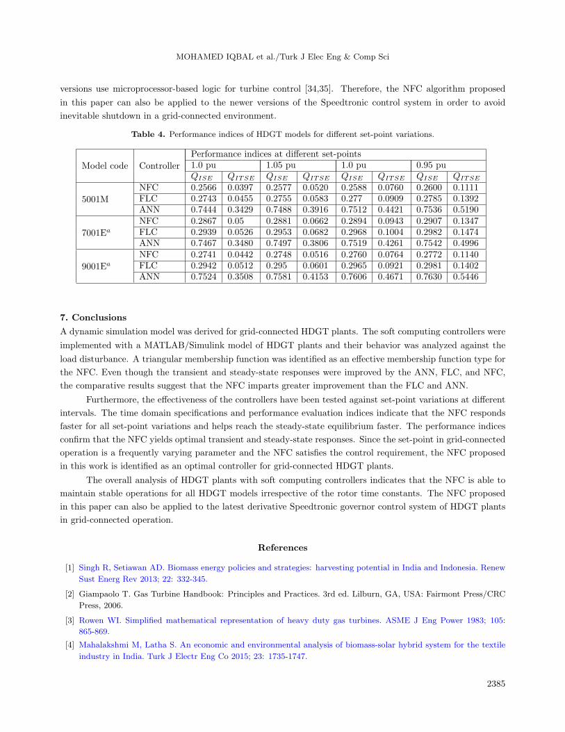
versions use microprocessor-based logic for turbine control [34,35]. Therefore, the NFC algorithm proposed
in this paper can also be applied to the newer versions of the Speedtronic control system in order to avoid
inevitable shutdown in a grid-connected environment.
Table 4. Performance indices of HDGT models for different set-point variations.
Model code Controller
Performance indices at different set-points1.0 pu 1.05 pu 1.0 pu 0.95 puQISE QITSE QISE QITSE QISE QITSE QISE QITSE
5001M
NFC 0.2566 0.0397 0.2577 0.0520 0.2588 0.0760 0.2600 0.1111FLC 0.2743 0.0455 0.2755 0.0583 0.277 0.0909 0.2785 0.1392ANN 0.7444 0.3429 0.7488 0.3916 0.7512 0.4421 0.7536 0.5190
7001Ea
NFC 0.2867 0.05 0.2881 0.0662 0.2894 0.0943 0.2907 0.1347FLC 0.2939 0.0526 0.2953 0.0682 0.2968 0.1004 0.2982 0.1474ANN 0.7467 0.3480 0.7497 0.3806 0.7519 0.4261 0.7542 0.4996
9001Ea
NFC 0.2741 0.0442 0.2748 0.0516 0.2760 0.0764 0.2772 0.1140FLC 0.2942 0.0512 0.295 0.0601 0.2965 0.0921 0.2981 0.1402ANN 0.7524 0.3508 0.7581 0.4153 0.7606 0.4671 0.7630 0.5446
7. Conclusions
A dynamic simulation model was derived for grid-connected HDGT plants. The soft computing controllers were
implemented with a MATLAB/Simulink model of HDGT plants and their behavior was analyzed against the
load disturbance. A triangular membership function was identified as an effective membership function type for
the NFC. Even though the transient and steady-state responses were improved by the ANN, FLC, and NFC,
the comparative results suggest that the NFC imparts greater improvement than the FLC and ANN.
Furthermore, the effectiveness of the controllers have been tested against set-point variations at different
intervals. The time domain specifications and performance evaluation indices indicate that the NFC responds
faster for all set-point variations and helps reach the steady-state equilibrium faster. The performance indices
confirm that the NFC yields optimal transient and steady-state responses. Since the set-point in grid-connected
operation is a frequently varying parameter and the NFC satisfies the control requirement, the NFC proposed
in this work is identified as an optimal controller for grid-connected HDGT plants.
The overall analysis of HDGT plants with soft computing controllers indicates that the NFC is able to
maintain stable operations for all HDGT models irrespective of the rotor time constants. The NFC proposed
in this paper can also be applied to the latest derivative Speedtronic governor control system of HDGT plants
in grid-connected operation.
References
[1] Singh R, Setiawan AD. Biomass energy policies and strategies: harvesting potential in India and Indonesia. Renew
Sust Energ Rev 2013; 22: 332-345.
[2] Giampaolo T. Gas Turbine Handbook: Principles and Practices. 3rd ed. Lilburn, GA, USA: Fairmont Press/CRC
Press, 2006.
[3] Rowen WI. Simplified mathematical representation of heavy duty gas turbines. ASME J Eng Power 1983; 105:
865-869.
[4] Mahalakshmi M, Latha S. An economic and environmental analysis of biomass-solar hybrid system for the textile
industry in India. Turk J Electr Eng Co 2015; 23: 1735-1747.
2385

MOHAMED IQBAL et al./Turk J Elec Eng & Comp Sci
[5] Mustafa MIM, Joseph XR, Arunkumar D, Rajkumar G, Selvakumar P, Tamilarasan C. A sample survey on biomass
gasifier power plants. In: International Conference on Emerging Technologies in Renewable Energy; 18–21 August,
2010; Chennai, India. Ref. no. P-87.
[6] Koochakian Jazi M, Tafreshi SMM, Jafari M. Design of a frequency control system in a microgrid containing HVAC.
Turk J Electr Eng Co 2016; 24: 2042-2052.
[7] Hafiz F, Abdennour A. An adaptive neuro-fuzzy inertia controller for variable-speed wind turbines. Renew Energ
2016; 92: 136-146.
[8] Kant Pandey S, Mohanty SR, Kishor N. A literature survey on load–frequency control for conventional and
distribution generation power systems. Renew Sust Energ Rev 2013; 25: 318-334.
[9] Ghorbani H, Ghaffari A, Rahnama M. Constrained model predictive control implementation for a heavy-duty gas
turbine power plant. WSEAS Trans Syst Control 2008; 3: 507-516.
[10] Najimi E, Ramezani MH. Robust control of speed and temperature in a power plant gas turbine. ISA T 2012; 51:
304-308.
[11] Nakamoto M, Kokubo T, Kamito A, Shimizu K. Cascade control using GPC and LQR for a NOx reduction process
of a thermal power plant. Transactions of the Society of Instrument and Control Engineers 2002; 2: 98-107.
[12] Kiat Yee S, Milanovic JV, Hughes FM. Overview and comparative analysis of gas turbine models for system stability
studies. IEEE T Power Syst 2008; 23: 108-118.
[13] Mustafa MIM, Joseph XR. A review of controllers for isolated and grid connected operation of biomass power
plants. In: International Conference on Renewable Energy Technologies; 16–17 December, 2011; Coimbatore, India.
pp. 366-371.
[14] Jurado F, Ortega M, Cano A, Carpio J. Neuro-fuzzy controller for gas turbine in biomass-based electric power
plant. Electr Pow Syst Res 2002; 60: 123-135.
[15] Mustafa MIM, Joseph XR. Fuzzy self-tuning PID controller for Speedtronic governor controlled heavy duty gas
turbine power plants. Electr Pow Compo Sys 2014; 42: 1485-1494.
[16] Johnson D, Miller RW, Ashley T. Speedtronic Mark V Gas Turbine Control System. GER-3658D. Boston, MA,
USA: General Electric Company, 1996.
[17] Balamurugan S, Xavier RJ, Jeyakumar AE. Control of heavy duty gas turbine plants for parallel operation using
soft computing techniques. Electr Power Compo Sys 2009; 37: 1275-1287.
[18] Sivanandam SN, Deepa SN. Principles of Soft Computing. New Delhi, India: John Wiley & Sons, 2007.
[19] Jang JSR. ANFIS: Adaptive-network-based fuzzy inference system. IEEE T Syst Man Cyb 1993; 23: 665-685.
[20] Balamurugan S, Xavier RJ, Jeyakumar AE. Selection of governor and optimization of its droop setting and rotor
time constant for heavy-duty gas turbine plants. Indian J Power River Val Dev 2007; 57: 35-37.
[21] Mustafa MIM, Joseph Xavier R, Kanakaraj J. Optimization of droop setting using genetic algorithm for Speedtronic
governor controlled heavy duty gas turbine power plants. WSEAS Trans Power Syst 2016; 11: 117-124.
[22] Fausett L. Fundamentals of Neural Networks Architectures, Algorithms and Applications. Upper Saddle River, NJ,
USA: Prentice Hall, 1994.
[23] Kocyigit N. Fault and sensor error diagnostic strategies for a vapor compression refrigeration system by using fuzzy
inference systems and artificial neural network. Int J Refrig 2015; 50: 69-79.
[24] Sisworaharjo NS, El-Sharkh MY, Alam MS. Neural network controller for micro turbine power plants. Elect Power
Sys Res 2008; 78: 1378-1384.
[25] Martins FG. Tuning PID controllers using the ITAE criterion. Int J Eng Educ 2005; 21: 867-873.
[26] Rajesh R. Fuzzy logic control - A quick review. International Journal of Wisdom Based Computing 2011; 1: 11-22.
2386

MOHAMED IQBAL et al./Turk J Elec Eng & Comp Sci
[27] Sahin ME, Okumus HI. A fuzzy-logic controlled PV powered buck-boost DC-DC converter for battery-load system.
In: International Symposium on Innovations in Intelligent Systems and Applications; 2–4 July 2012; Trabzon,
Turkey. New York, NY, USA: IEEE. pp. 1-5.
[28] Altas IH, Sharaf AM. A novel maximum power fuzzy logic controller for photovoltaic solar energy systems. Renew
Energ 2008; 33: 388-399.
[29] Altas IH, Sharaf AM. A generalized direct approach for designing fuzzy logic controllers in Matlab/Simulink GUI
environment. International Journal of Information Technology and Intelligent Computing 2007; 1: 1-27.
[30] Khuntia SR, Panda S. Simulation study for automatic generation control of a multi-area power system by ANFIS
approach. Appl Soft Comp 2012; 12: 333-341.
[31] Siddique N. Neuro-fuzzy control. In: Widrow B, editor. Intelligent Control. Basel, Switzerland: Springer Interna-
tional Publishing, 2014. pp. 179-216.
[32] Vieira J, Dias FM, Mota A. Neuro-fuzzy systems: a survey. In: 5th WSEAS NNA International Conference on
Neural Networks and Applications; 25–27 March 2004; Udine, Italy.
[33] Zhao J, Bose BK. Evaluation of membership functions for fuzzy logic controlled induction motor drive. In: IEEE
28th Annual Conference of the IECON; 5–8 November 2002; Seville, Spain. New York, NY, USA: IEEE. pp. 229-234.
[34] Barker W, Cronin M. SPEEDTRONIC Mark VI Turbine Control System. GE Power Systems GER-4193A. Boston,
MA, USA: General Electric, 2000.
[35] Dey N. Managing an effective centralized control room for brown field projects in gas plant. In: International
Petroleum Technology Conference; 6–9 December 2015; Doha, Qatar.
2387