A multitube differential pressure manometer for measuring the ...
38
ILL INO S UNIVERSITY OF ILLINOIS AT URBANA-CHAMPAIGN PRODUCTION NOTE University of Illinois at Urbana-Champaign Library Large-scale Digitization Project, 2007.
Transcript of A multitube differential pressure manometer for measuring the ...

ILL INO SUNIVERSITY OF ILLINOIS AT URBANA-CHAMPAIGN
PRODUCTION NOTE
University of Illinois atUrbana-Champaign Library
Large-scale Digitization Project, 2007.


UNIVERSITY OF ILLINOIS ENGINEERING EXPERIMENT STATION
Bulletin Series No. 410
A MULTITUBE DIFFERENTIAL PRESSURE MANOMETER
FOR MEASURING THE AVERAGE FLOW OF FLUIDS
IN CLOSED DUCTS
GEORGE B. CLARK
Associate Professorof Mining Engineering
Published by the University of Illinois, Urbana

3050-3-53-51703 OF ILLNO.S:: PRESS ::

CONTENTS
I. INTRODUCTION 5
II. METHODS OF MEASURING AIR FLOW 6
1. Orifice Metering 6
2. Vane-Type Anemometers 6
3. Hot-Wire Anemometers 6
4. Pitot Tube 7
III. THEORY OF AVERAGE-VELOCITY MANOMETERS 9
5. Volume of Revolution 10
6. Right Circular Cylinder with Core 10
7. Curved Small Bore Cylindrical Tubing 11
IV. CONSTRUCTION AND TESTING OF THE MANOMETER 13
V. ERROR OF SIMPLE DIFFERENTIAL PRESSURE MANOMETERS 17
8. Free Vibration 18
9. Forced Vibration 19
10. Forced-Damped Vibration 20
VI. ERROR OF THE CURVED-TUBE MANOMETER 24
FIGURES
1. Vertical Section of First Type Manometric Tube 11
2. Three Curves of the Family of Eq. 15 12
3. Essentials of the Average-Velocity Gage 13
4. Average-Velocity Gage Showing Component Parts 14
5. Beats Created When the Frequency of the Imposed Periodic Force Is Slightly
Different from That of the Oscillating Liquid 20
6. Oscillation, with Increasing Amplitude, Created by a Condition of Resonance 21
7. Amplitudes of Forced Oscillations as the Function of the Frequency for Various
Values of the Damping Factor 3 22
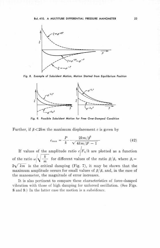
8. Example of Subsident Motion, Motion Started from Equilibrium Position 23
9. Possible Subsident Motion for Free Over-Damped Condition 23
10. Scheme for Oscillation of the Liquid Level about the Origin in a Manometric Tube 24
11. Time-Displacement Curve for Oscillation about the Origin Compared with
Circular Cosine Curve of the Same Period 26
12. Condition for Oscillation about a Point Other than the Origin 27

I. INTRODUCTION
Various methods have been devised to measure the flow of fluids inclosed ducts - especially the flow of water, air, and other gases. Measur-ing the quantity of air flowing through mine openings or the flow of airin standardized fan tests involves the type of fluid flow with which thisBulletin is primarily concerned. Many standard methods of measuringair flow are inaccurate, time-consuming, or both. Particularly time-consuming are the methods used in fan testing; for example, such testingis often difficult to incorporate in a three-hour laboratory period such asis customary in undergraduate teaching.
There are few satisfactory means of measuring the average flow orthe quantity of flow past a given cross-section in a duct; most measuringmethods are not compatible with all test conditions. Thus the use ofcalibrated orifices cannot be readily adapted to fan testing and to someother operations that require accurate flow metering, because the orificeconstricts the flow of fluid. Again, calibration of the duct and the use ofa center factor may cause a large error if the pattern of flow changes.
A manometer developed in the University of Illinois mine ventilationlaboratory uses twenty fixed pitot tubes, measures the velocity pressuressimultaneously at twenty points at a given cross-section of the duct,extracts the square root of each velocity pressure, averages the twentysquare roots, and multiplies the result by a constant which is adjustedfor the specific weight of air in the duct during the test. This proceduregives the average velocity or quantity in one reading. In addition themanometer does not seriously obstruct the duct, and automaticallyadjusts for any changes in flow pattern at the position of the pitot tubes.
The present Bulletin describes the theory and construction of thisaverage-velocity gage and analyzes possible sources of error in readingswhich are made with it.
II. METHODS OF MEASURING AIR FLOW1. Orifice Metering
In this type of flow measurement, the pressure drop caused by theconstricting effect of an orifice in the duct is known to be a function ofthe quantity of fluid flowing through the orifice. The measurement of thepressure drop across a calibrated orifice will give the quantity flowingor the average velocity of the fluid.
2. Vane-Type Anemometers
These instruments consist of either propeller or radial-blade designs,the blades being attached to a rotating axis which in turn is geared toa mechanism that will count the revolutions of the axis. When thisanemometer is placed in an air stream the rotation of the blade assemblywill measure the amount of air passing the blades, which in turn gives thevelocity. The instrument measures the approximate amount of air passingthrough its whole cross-sectional area, and consequently does not measurethe velocity at a point. It is not adaptable to the measurement of aver-age flow in relatively small ducts. However, it is accurate enough forflow measurements in mine drifts, where great precision is not required.
3. Hot-Wire Anemometer
In this instrument the cooling power of moving air is used to measurethe velocity. A small length of platinum wire is included in a bridgecircuit in order to measure its resistance accurately. The heated platinumwire is placed in the air stream and the amount of electric current nec-essary to maintain its temperature at a fixed value is measured. Thecurrent necessary to maintain this temperature is a function of thevelocity of the air passing the wire. An ammeter properly connected andcalibrated may be used to measure the velocity of the air which ispassing the heated wire.
The hot-wire anemometer measures the velocity of air flowing past avery small area; this velocity so determined can be considered to be thevelocity at a given point. If the velocity of air is measured at enoughproperly spaced points across the cross-section of a closed duct, the aver-age of these readings will be close to the average velocity of the air.(See NAFM code on page 7.)

Bul.410. A MULTITUBE DIFFERENTIAL PRESSURE MANOMETER
4. Pitot TubeThe pitot tube and the pressure-indicating instruments employed with
it are widely used to measure air flow. Since the pitot tube is a basic partof the particular anemometer with whose development this paper isconcerned, it is described in some detail in this section.
The two openings of a pitot tube connected to the legs of a U-tubemanometer give the difference between the total pressure and the staticpressure which is the velocity pressure. The relation between the velocitypressure so measured and the velocity of the air flowing past the endof the pitot tube is
V = 1097.4 (1)
whereV is velocity in ft/minhi is velocity pressure in inches water gagew is the specific weight of air in lb/cu ft
The lengths of tubing and the U-tube constitute a closed system. Thatis, the static plus the velocity pressure on one leg of the tube are opposedby the static pressure only on the other leg; a reading on the scale of theU-tube thus measures velocity pressure. The same principle is employedin the average velocity manometer. It should be noted, however, that thestatic pressure is assumed to be the same at all points across the cross-section of the duct as it is at the end of the pitot tubes. Consequently,the static pressure is measured at the skin of the duct instead of at theposition of the pitot tube within the duct.
The operation of making the pitot tube traverse of a closed duct inorder to determine the average velocity as well as the quantity of the airflow is tedious under the most ideal working conditions. Enough pointsmust be taken as velocity measuring stations so that the average of thesereadings will approximate closely the average velocity of the air flowingthrough the duct, provided that each velocity thus determined can betaken as representative of equal portions of the cross-sectional area of theduct. The number of points prescribed by the National Association ofFan Manufacturers is twenty.
The individual velocities are ordinarly calculated in feet per minuteby the use of Eq. 1.
The average velocity is then determined as follows:
V -I- V. - V. -I- VVa
x 2 s . . . .
v =
V.• = ". , .• . ..... . ..

8 ILLINOIS ENGINEERING EXPERIMENT STATION
or
1097.4 1,
Vav = 1 h (3)
The problem suggested by this mathematical statement is to designan instrument which will do mechancially the operation indicated by
N/ -hii , the quantity in front of the summation sign being a constant
for a given psychrometric condition of the air at the time of the test.Adjustment for the variation in the weight of air is only a matter ofproper calibration, as is shown in Chap. IV.
III. THEORY OF AVERAGE-VELOCITY MANOMETERS
In an ordinary manometer the volume of liquid displaced by thevelocity pressure of the air is directly proportional to the velocity pres-sure. However, if by appropriate design of the manometer tube thequantity of liquid is made proportional to the square root of a givenvelocity pressure and if all the required velocity pressures in a duct aremeasured simultaneously with the same number of manometers, the totalquantity of liquid displaced represents the quantity on the right of thesummation sign. If an appropriate variable scale is provided so that thequantity of liquid thus displaced is measured for the appropriate weightof air on this scale, which also takes the values 1097.4 and n into account,the average velocity may be read directly.
These operations are easily performed. First the static pressure istaken from points on the surface of the duct; this means that the staticpressure is assumed to be constant over the cross-section. The totalpressure (static plus velocity) is measured by placing at the proper pointsin the duct, fixed facing total-pressure tubes of small diameter. Each isconnected to the top openings of a system of an equal number of manom-eter tubes of appropriate design. The lower ends of these are connectedto a common reservoir and are opposed in a closed system by the staticpressure through a tube which is connected to the top of the volume-measuring tube. For reading the average velocity the liquid in themeasuring tube must always be brought back to its zero reference level,which is also the zero coordinate of the curved tubes, so that the staticpressure will cancel properly (reach null balance), and so that the oildisplaced in each tube will be proportional to the square root of its ap-plied velocity pressure.
Each manometric tube is so designed that the volume of the oil dis-placed from it is proportional to the square root of the height of the oildisplaced (velocity pressure).
That is,
Q = K (4)where
Q is the quantity of oil displacedK is a constant of proportionalityh is the height of oil displaced (velocity pressure)
Three types of manometric tubes fulfill this requirement.
9
ILLINOIS ENGINEERING EXPERIMENT STATION
5. Volume of RevolutionDifferentiating Eq. 4,
dQ = Kh-mdh (5)
Also, for any infinitesimal height the volume is
dQ = irr2dh (6)
Equating Eqs. 5 and 6 and solving for r, the variable radius of therequired volume of revolution is
r . h-= (7)
This is the equation of the required curve.The fact that this hyperbola is asymptotic to both the h and r axes
introduces a difficulty in designing a manometer which will cover therange of velocities desired - from zero to some appropriate fixed value.It is seen that the integral
Q f= wr2dh (8)
does not exist. However, an integral from a very small lower limit doesexist:
Q = fh rrdh (9)
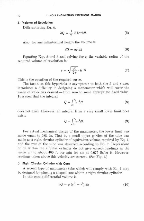
For actual mechanical design of the manometer, the lower limit wasmade equal to 0.01 in. That is, a small upper portion of the tube wasmade as a right circular cylinder of equivalent volume required by Eq. 4,and the rest of the tube was designed according to Eq. 7. Depressionsof oil within the circular cylinder do not give correct readings in therange up to about 400 ft per min for air at 0.075 lb/cu ft. However,readings taken above this velocity are correct. (See Fig. 1.)
6. Right Circular Cylinder with Core
A second type of manometer tube which will comply with Eq. 4 maybe designed by placing a shaped core within a right circular cylinder.
In this case a differential volume is
dQ = ir (r 2- r2) dh
Bul. 410. A MULTITUBE DIFFERENTIAL PRESSURE MANOMETER
Equating with Eq. 5 and solving for r,
2 Kr = r 2 rh-
27rhyi (11)
As in the first type, the integral Eq. 8 does not exist, and similarprovisions - choice of a very small lower limit for h - must be made inthe design of the core.
0'1/I I
0-
--
2--
3 -
Fig. 1. Vertical Section of First Type Manometric Tube
7. Curved Small Bore Cylindrical TubingA third design of tube which satisfies Eq. 4 is a curved small bore
tube in which the surface of the liquid is assumed to remain perpendicularto the axis of the tube. The volume of liquid displaced is then propor-tional to the length of the tube.
Here
dQ = K1 - (dx) 2 + (dh) 2 (12)
Equating with Eq. 5
S(dh) = (dx) 2 + (dh)2
4h
dx = _ 1 dh4h
ILLINOIS ENGINEERING EXPERIMENT STATION
or, by integration
K 2 K 2 . 2N/x =- Vh - h + - sin-1 K + C (15)
If it is assumed that the curve goes through the origin, the constantC is zero.
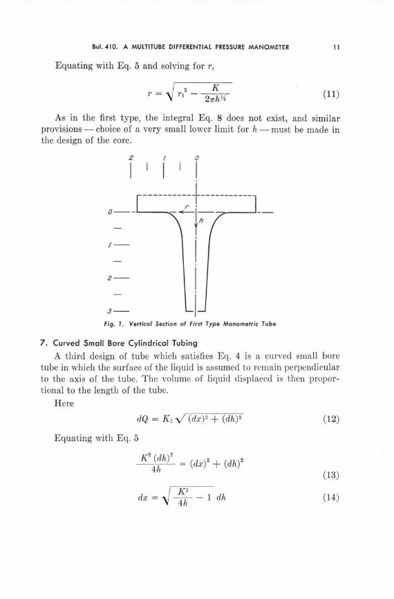
Equation 15 yields a whole family of curves. A given curve is ob-tained by assigning a value to K. It is noted that the curve does notexist for negative values of h or values of h larger than K /4. The upperlimiting value of the family of curves is found by setting K 2/4 = h.Equation 15 becomes
x = h sin 1 (1) = h- (16)
Equation 16 is a straight line whose slope is 2/7r. (See Fig. 2.)
Horizont/al Distance x
di
Fig. 2. Three Curves of the Family of Eq. 15
IV. CONSTRUCTION AND TESTING OF THE MANOMETER
In the early development of the gage only the first type (volume ofrevolution) of manometer tube had been conceived. A test model usingsix containers of this type, machined from plastic, proved successful.The scale factor was K = 1, so that the tubes were too large for a work-ing model with twenty tubes. Reducing the scale factor to K - % intro-duced problems in machining which made it very difficult to producecontainers with the exact hyperbolic shape to a required accuracyof -+0.001 in. on the radius.
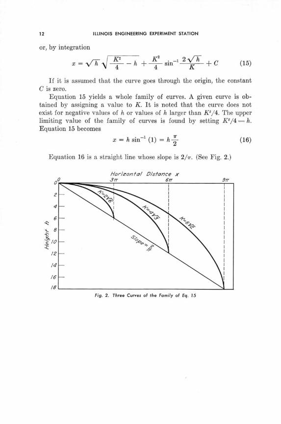
Fig. 3. Essentials of the Average-Velocity Gage
The second type of container with core does not appear practicalfor gage construction, although its possibilities have not been fullyinvestigated.
The curved small bore tube was subsequently conceived, and with anappropriate design of frame for mounting, the whole was designed andassembled. (Figs. 3 and 4) The glass tubing had to be small enough sothat the meniscus of the fluid would remain normal to the axis of the tube
ILLINOIS ENGINEERING EXPERIMENT STATION
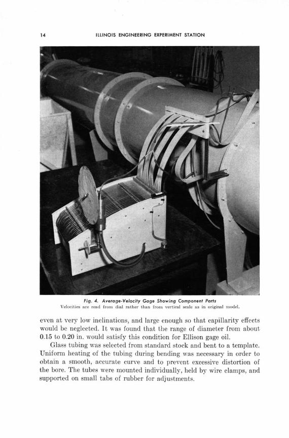
Fig. 4. Average-Velocity Gage Showing Component PartsVelocities are read from dial rather than from vertical scale as in original model.
even at very low inclinations, and large enough so that capillarity effectswould be neglected. It was found that the range of diameter from about0.15 to 0.20 in. would satisfy this condition for Ellison gage oil.
Glass tubing was selected from standard stock and bent to a template.Uniform heating of the tubing during bending was necessary in order toobtain a smooth, accurate curve and to prevent excessive distortion ofthe bore. The tubes were mounted individually, held by wire clamps, andsupported on small tabs of rubber for adjustments.
Bul.410. A MULTITUBE DIFFERENTIAL PRESSURE MANOMETER
The movable measuring tube was mounted on a vertical screw in turnmounted parallel to a fixed plastic rod 1 in. in diameter, on which wassecured a reading scale. The scale was drawn on vellum. Its basis ofconstruction is as follows:
Whend is the diameter of manometer tubesD is the diameter of measuring tubeH is the height of oil displaced into measuring tubeL is the length of oil column displaced in small tubes
Then
L, = K \r hi (17)
Q, = r- Li (18)
1097.4Vav = _ (19)
20 V- wor
1097.4 DVav = --. H (20)
20K / w d2
In Eq. 20 appropriate values may be chosen for D, d and K and ascale constructed for values of w, the weight of air, for the range ofweights that may be found in a given laboratory. That is, the weight ofair must be determined, and the scale on the vertical plastic rod must berotated to the proper position for a given weight of air. If the weightof air changes during a fan test, for example, the scale may be imme-diately adjusted to the proper weight of air. The present test modelemploys small tubes with an inside diameter of about 0.175 in. and ameasuring tube of approximately 1 in. inside diameter.
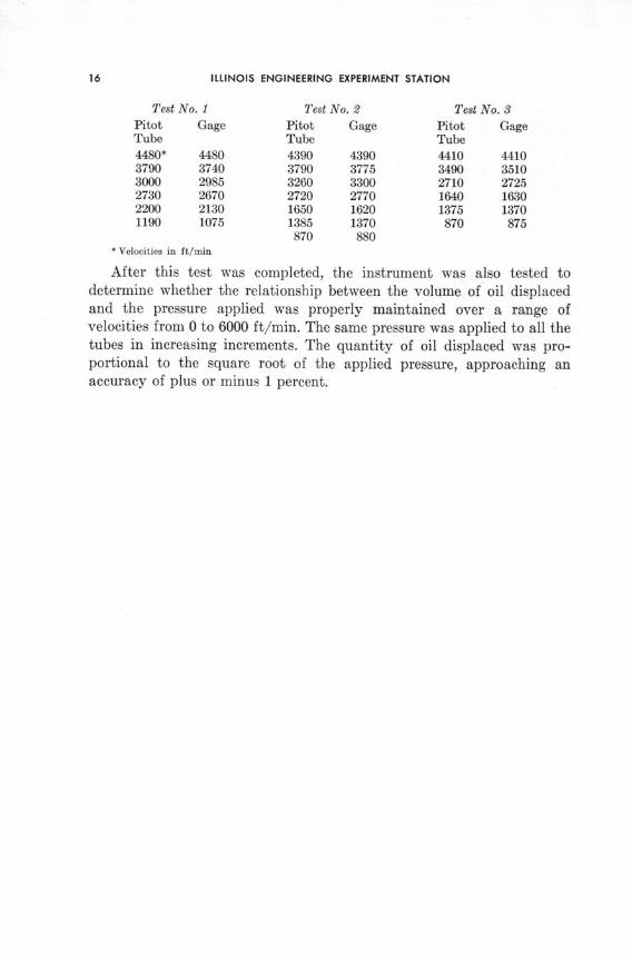
The best method available for testing the average velocity gage isby comparison with a standard pitot tube traverse. The gage was firstleveled in the plane normal to the plane of the tubes and then as closelyas possible in the plane of the tubes. When the gage was leveled properly,the readings compared very favorably with the results of the pitot tubetraverse. The results of three final tests are given in the following table.The last test reported shows the difference in velocities to be consistentlyless than 1 percent, a remarkable agreement in view of the fact that thegage was constructed with standard rather than precision tubing.
ILLINOIS ENGINEERING EXPERIMENT STATION
Test No. 1Pitot GageTube4480* 44803790 37403000 29852730 26702200 21301190 1075
Test No. 2
Pitot GageTube
4390 43903790 37753260 33002720 27701650 16201385 1370870 880
Test No. 3Pitot GageTube4410 44103490 35102710 27251640 16301375 1370870 875
* Velocities in ft/min
After this test was completed, the instrument was also tested todetermine whether the relationship between the volume of oil displacedand the pressure applied was properly maintained over a range ofvelocities from 0 to 6000 ft/min. The same pressure was applied to all thetubes in increasing increments. The quantity of oil displaced was pro-portional to the square root of the applied pressure, approaching anaccuracy of plus or minus 1 percent.
V. ERROR OF SIMPLE DIFFERENTIAL PRESSURE MANOMETERS
Certain investigators have found that under given conditions of flowthe errors in the measurement of air and other fluids by differentialpressure manometers may be of the order of 100 percent or even greater.Judd and Pheley (1 * in their study of the flow of air with Venturi meters,orifices, nozzles and pitot tubes concluded that:
1. Pulsations in fluid flow are made up of sudden changes in velocityand pressure.
2. Largest pulsations are caused by pressure changes.3. Pressure changes are in the form of wave fronts which travel with
the velocity of sound.4. Velocity of pulsations is independent of the velocity of the fluid.5. The effect of pulsations is to increase the manometer reading. The
magnitude of the error so caused is a function of frequency, static pres-sure, type of meter and component devices.
6. Pulsation must be reduced or eliminated to insure correct readings.Lindahl( 2) showed that if the pressure varies as a sine wave, the
instantaneous pressure is given by
whereP = h + p sin 0 (21)
h is the average velocity pressure readingp is the maximum variation in pressureP is the instantaneous velocity pressureK is a constant
The value of the instantaneous velocity is given by
V = K (h + p sin 0) 2 (21a)
From these expressions the relation between the mean and averagevelocities is found to be
Vm Kh 2 (VaV-- Kh [1- P ) 10245 (h•)] (22)
*Parenthesized superscripts refer to correspondingly numbered entries in the References.
ILLINOIS ENGINEERING EXPERIMENT STATION
Therefore, the average of the velocity pressures is higher than thatof the velocities. The amount of this error is a function of the ratioof the amplitude of oscillations to the average pressure. For a ratio ofp/h = 1/4 the error introduced is only of the order of 0.4 percent - verysmall in comparison with errors actually present. Thus, uniform pulsa-tion does not appear to account for all the errors encountered in meteringthe flow of fluids. Pulsation accounts for large errors only when theamplitude of the pulsating meter is great; this may happen when thefrequency of the pulsation is very close to the characteristic frequencyof pulsation of the meter itself.
This development assumes that the meter is oscillating with the sameamplitude as the velocity pressure. For a non-damped meter this con-dition will obtain only if the restoring force is equal to maximum ampli-tude of the applied pressure (see below) and the frequency of thepressure oscillations is much greater than the natural frequency of themeter. When the meter is of the damped type (as most are), the maxi-mum amplitude depends on the relationship of a number of factors inthe equation of motion. The assumption in both cases is also that the typeof oscillation of the meter is simple harmonic in character, that is, thedifferential equation of motion is linear.
These points on oscillating characteristics as the causes of basic errorcan be best demonstrated by analyzing the behavior of a simple type ofmanometer. The simple U-tube may be treated mathematically withessentially the same equations as an elastically-restrained body. Itscharacteristics are also important for comparison with the more difficultcase of the manometer tubes employed in the average-velocity gage. Thethree important types of behavior to be analyzed are (1) free vibra-tion, (2) forced vibration, and (3) forced-damped vibration.
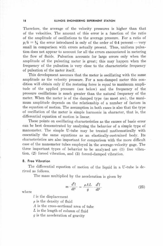
8. Free Vibration
The differential equation of motion of the liquid in a U-tube is de-rived as follows.
The mass multiplied by the acceleration is given by
d21 _ pAL d1 (23)m d - g (23)
where g dt2
I is the displacementp is the density of fluidA is the cross-sectional area of tubeL is the length of column of fluidg is the acceleration of gravity

Bul.410. A MULTITUBE DIFFERENTIAL PRESSURE MANOMETER
The restoring force is-2pAl (24)
Hence, the equation of motion is
pAL d2lg dt2 + 2pAl = 0 (25)
or
dt+ 1 = 0 (26)
The solution is of the form
= B cos wot + C sin wot (27)
where the frequency is
S= 2g (28)Land the period
T = 21r L (29)
If the following boundary conditions are assumed, the behavior maybe more completely demonstrated:
= 0
dldt-= vo = 0
1 = 10
and, from theseI = 10 cos Wo (30)
Hence, the oscillation is simple harmonic in character. If the tube isinclined at an angle a the frequency becomes
J/2g sin ao0 = L (31)
9. Forced VibrationIf a periodic force or pressure, P sin wt, acts on the liquid on one side
of the tube, the appropriate equation of motion is
d42m d + kl = P sin wt (32)
ILLINOIS ENGINEERING EXPERIMENT STATION
pALwhere m = pAL
gk = 2pA
One complete solution of Eq. 32 is
1 = B cos wot + C sin wot + Psinwtt (33)m (wo2 - w2)
The last term may be rewritten
P sin wt 1 (34)
W02
If W2/Wo2 is small compared to unity then the displacement is thatdue to the instantaneous value of the force. If the ratio is greater thanunity the force and deflection are opposite in sign. Finally, if the ratio isequal to unity, the displacement becomes infinite - that is, a condition ofresonance exists. Then a new solution is required:
P1 = B cos wat + C sin wot 2m- - t cos awt (35)
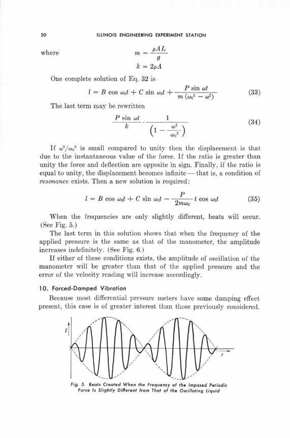
When the frequencies are only slightly different, beats will occur.(See Fig. 5.)
The last term in this solution shows that when the frequency of theapplied pressure is the same as that of the manometer, the amplitudeincreases indefinitely. (See Fig. 6.)
If either of these conditions exists, the amplitude of oscillation of themanometer will be greater than that of the applied pressure and theerror of the velocity reading will increase accordingly.
10. Forced-Damped Vibration
Because most differential pressure meters have some damping effectpresent, this case is of greater interest than those previously considered.
2
Fig. 5. Beats Created When the Frequency of the Imposed PeriodicForce Is Slightly Different from That of the Oscillating Liquid
Bul.410. A MULTITUBE DIFFERENTIAL PRESSURE MANOMETER
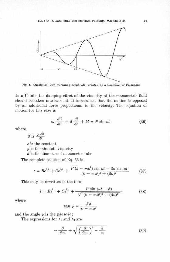
Fig. 6. Oscillation, with Increasing Amplitude, Created by a Condition of Resonance
In a U-tube the damping effect of the viscosity of the manometric fluidshould be taken into account. It is assumed that the motion is opposedby an additional force proportional to the velocity. The equation ofmotion for this case is
d2l dl
m d -3 d + kl = P sin wt (36)
where
SA ch
c is the constantj is the absolute viscosityd is the diameter of manometer tube
The complete solution of Eq. 36 is
= eX' , Ce' P (k - mW2) sin wt - Ow cos wt (t = B e + Ce + - - ( 3 7 )
(k - mW) 2 + (O)2
This may be rewritten in the form
l = Bet + Cet + P sin (o-t (38)V (k - mw) 2 + (3,) 2
wheretan = - m,- -
k - mw2
and the angle 4 is the phase lag.The expressions for X, and X2 are
-- 0 + ( ) (39)2_m_ 2#m m
ILLINOIS ENGINEERING EXPERIMENT STATION
and
k (40)2m 2m m
For values of 6 2 >4km the motion is not oscillatory but is a sub-sidence. For #2 <4km the quantities become complex and the motionbecomes oscillatory. The point at which 132 = 4km is that at which thechange from subsident to oscillatory motion occurs, and the quantity3 = 2/ km is known as the critical damping factor. For this condition(of critical damping) it is found that
X = X2 = - (41)
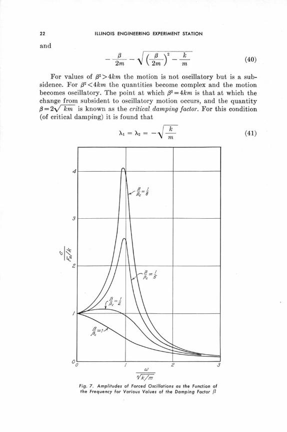
Fig. 7. Amplitudes of Forced Oscillations as the Function ofthe Frequency for Various Values of the Damping Factor 13
Bul. 410. A MULTITUBE DIFFERENTIAL PRESSURE MANOMETER
I2 'S
'S.5
2'*
2=e "-e -'~
Fig. 8. Example of Subsident Motion, Motion Started from Equilibrium Position
Fig. 9. Possible Subsident Motion for Free Over-Damped Condition
Further, if 0 < 2km the maximum displacement c is given by
P 2km/1cmax = 4km/ -2 (42)
k `/ 4km/l 2 - 1
If values of the amplitude ratio c/Fo/k are plotted as a function
of the ratio w0 -- for different values of the ratio i3/c, where 0,=
2--/ km is the critical damping (Fig. 7), it may be shown that themaximum amplitude occurs for small values of 3/13c and, in the case ofthe manometer, the magnitude of error increases.
It is also pertinent to compare these characteristics of force-dampedvibration with those of high damping for unforced oscillation. (See Figs.8 and 9.) In the latter case the motion is a subsidence.

VI. ERROR OF THE CURVED-TUBE MANOMETER
To evaluate the accuracy of the average-velocity gage its oscillatingcharacteristics must be considered. The simplest case is that in whichdamping is neglected and there is no imposed force acting on the mano-metric fluid. That is, the surface of the liquid is considered to be makingsmall oscillations about the origin as shown in Fig. 10.
Fig. 10. Scheme for Oscillation of the Liquid Level about the Origin in a Manometric Tube
The differential equation of motion for this system is
(L - 1) Ad9 - pA- d + pAh = 0 (43)
The restoring force is identical with that for a vertical tube of the samediameter and height. As a first approximation the displacement is con-sidered to be small as compared to L; that is, the mass of moving fluid isassumed to be constant. This supposition permits the equation of motionto be placed in an analytically solvable form. The tube is assumed to beconnected, as shown, to a very large reservoir of fluid, which will providethe physical condition necessary to make the equation applicable. Thiscondition effectively exists in the average-velocity gage. The loss invelocity head at the entrance to the reservoir is neglected, as is theeffect of centrifugal force along the curved tube.
If the value of h is substituted with Eq. 43 and the above approxima-tion is made, the equation of motion becomes
d2 1 gdt2 LK 1 = 0 (44)

Bul.410. A MULTITUBE DIFFERENTIAL PRESSURE MANOMETER
dlThe order of the equation is reduced by letting v=-- and solving
the resulting equation:dv 9 g 12 (45)
vdv = - g f dl (46)
0 LK 2
For the conditions
t =0 1oV = 0
the following results:
\ / 3LK l - (47)or
3LK 2 r dldt = J 2 f I dl (48)S2g Jex / y -1 -
This may be placed in a recognizable form (' ) by substituting
1x = - (49)
Equation 48 becomes
t 3LK 2 r dx (50)= 2gli A V 1 - x3
This is an elliptic integral, the member under the radical having onereal and two complex roots, which may be placed in the standard Le-Gendre form by making the substitution
cos 0- = (51)-\/3V-+ 1 - x
This converts Eq. 50 to
t= LK2 0 do (= 2gli o -/ 1 - sin 2 750 . sin 2 (>
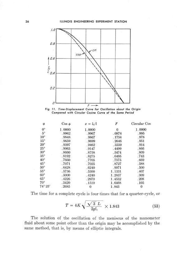
If the value of the integral is denoted by F, the following table indi-cates the time displacement values for one-quarter cycle. This is plottedin Fig. 11 for comparison with a circular cosine curve of the samefrequency.
ILLINOIS ENGINEERING EXPERIMENT STATION
Fig. 11. Time-Displacement Curve for Oscillation about the OriginCompared with Circular Cosine Curve of the Same Period
0 Cos 4 x = 11/l F Circular Cos
0° 1.0000 1.0000 0 1.000050 .9962 .9967 .0874 .995
100 .9848 .9867 .1754 .978150 .9659 .9699 .2646 .951200 .9397 .9462 .3559 .914250 .9063 .9147 .4499 .866300 .8660 .8758 .5474 .809350 .8192 .8275 .6495 .743400 .7660 .7705 .7575 .669450 .7071 .7025 .8727 .588500 .6428 .6240 .9971 .500550 .5736 .5300 1.1331 .407600 .5000 .4240 1.2837 .309650 .4226 .2970 1.4532 .208700 .3420 .1510 1.6468 .10574025' .2685 0 1.843 0
The time for a complete cycle is four times that for a quarter-cycle, or
T = 4K L X 1.843 (53)2gli
The solution of the oscillation of the meniscus of the manometerfluid about some point other than the origin may be accomplished by thesame method, that is, by means of elliptic integrals.
Bul. 410. A MULTITUBE DIFFERENTIAL PRESSURE MANOMETER
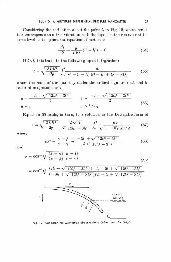
Considering the oscillation about the point lo in Fig. 12, which condi-tion corresponds to a free vibration with the liquid in the reservoir at thesame level as the point, the equation of motion is
dt2l (1 - lo2) = 0 (54)
If l<lo this leads to the following upon integration:
S3LK2 r dl (55)S 2g V - (1 - li) (12 + 11 + ll 2 - 3152)
where the roots of the quantity under the radical sign are real, and inorder of magnitude are:
-11 +\/ 12102 - 3l1 -l -- 121o2 - 3112
(56)
Equation 55 leads, in turn, to a solution in the LeGendre form of
3LK 2 2 V"2 __ o do (57)
N 2g 121o2 - 3/12 o V 1 - Ki 2 sin 2 (where
a - --311 +- 12/02 -312K 1
2 a - 3 - V 12 - 32 (58)a - Y 2 v/ 12102 -3 12
and
_ ( - 1)(a)-
(a - f) ( - 7) (59)
= cos-i (31 + V/ 12o2 - 3112 )(-l, - 21+ V 12/02 - 3/12
(-31, + V 12102 - 31i2 )(21 + 4i + V 121o2 - 3l12)
"I
Fig. 12. Condition for Oscillation about a Point Other than the Origin
ILLINOIS ENGINEERING EXPERIMENT STATION
When 1 >10 the solution of Eq. 54 leads to
S3LK 2 f1 4 dl (60)t = 2g v - ( -/ (1 2 2v+ l + l" - 302)
The quantity under the radical sign has three real roots for valuesof 10> l22. They are, in order of magnitude:
- l1 - -/ 12102 - 3122a = l1 2 = 2
2 "(61)
12 + / 12102 - 3122
This development leads to the LeGendre form of
S3LK 2 2V2 _ do (62)2g 312 + V 1212 - 3122 V 1 - Ks2 sin2 4
where
K 22 a - 32 - 12102 - 3122 (63)a- 312 + V 121o2 - 312
and
- 1 co os j 2-1 + 12 - 12o - 3 2 (64)a - I 312 - V 1210o2 - 3122
These waves are also elliptic cosines, and their periods are four timesthe expression in front of the integral sign. The frequencies of the upwarddisplacement and the downward are different, the latter being greater. Acomparison shows that the time of oscillation increases as the centralpoint of oscillation is moved downward along the curve because 1o in-creases and L decreases.
A condition of resonance therefore could not occur for the oscillationof the manometer fluid unless a very complex pressure wave with similarfrequency characteristics were imposed upon it. This is very unlikely tooccur in practice. Even in the case of free forced vibration (withoutviscous damping), then, the curved manometer tubes are self-damping.
A simple test was performed with the test model of the gage to observeits oscillating characteristics. The liquid in one of the tubes was displacedand its movement observed when it was released. The movement wasclearly a subsidence for the gage as constructed, probably because ofviscous damping of the manometric fluid.
From the observed fluctuations of the velocity pressures in the curvedtubes it appears, superficially at least, that the largest variations in

Bul. 410. A MULTITUBE DIFFERENTIAL PRESSURE MANOMETER
velocity are not necessarily periodic but consist of intermittent surges.While such occurrences could cause a considerable error in a standardpitot tube traverse, they seem to cause no appreciable error in the aver-age-velocity gage. That is, the total flow of air through a duct may beassumed to be reasonably constant for given fan speed and delivery con-ditions. Therefore, an increase in velocity in one portion of the ductcross-section will be accompanied by a corresponding decrease in velocityelsewhere. Such a supposition is borne out by the fact that for a givenfan delivery the liquid in the volume-measuring tube remains constanteven though the velocity in individual tubes is fluctuating considerably.This fluctuation is logically due to constant total flow conditions whichin turn result in a displacement of fluid in one tube being compensatedby a rise in one or more of the others. Actually, the behavior of the fluidis very complex and could be evaluated rigorously only by the solutionof twenty simultaneous equations. The information obtained for one tube,however, makes a more detailed examination appear unnecessary.
Working models of the average-velocity gage have been constructedand these are now in use in the mine ventilation laboratory at theUniversity of Illinois.

REFERENCES
1. Judd, Horace, and D. B. Pheley, "Effects of Pulsation on Flow of Gases." OhioState University Eng. Exp. Sta. Bulletin No. 24, March 14, 1923.
2. Lindahl, E. J., "Pulsation and Its Effect on Flow Meters." Trans, A.S.M.E., Vol.68, p. 883, 1946.
3. Hancock, H., Elliptic Integrals.


![DIGITAL DIFFERENTIAL COMPACT PRESSURE TRANSMITTER Digital Pressure Gauge … · 2019. 12. 3. · PRESSURE GAUGE Digital Pressure Gauge & Digital Manometer [Input setting 2 ] SETTING](https://static.fdocuments.net/doc/165x107/60b001340dff284ff85b02be/digital-differential-compact-pressure-transmitter-digital-pressure-gauge-2019-12.jpg)