A Multi-Robot Platform for Mobile Robots with Multi-Agent ... · A Multi-Robot Platform for Mobile...
98
A Thesis submitted to the Department of Informatics in partial fulfillment of the requirements for the degree of Master of Science A Multi-Robot Platform for Mobile Robots with Multi-Agent Technology Technical Aspects of Multimodal Systems Distributed Systems and Information Systems University of Hamburg submitted by Sebastian Rockel July 2011 supervised by Prof. Dr. Jianwei Zhang Dr. Lars Braubach
Transcript of A Multi-Robot Platform for Mobile Robots with Multi-Agent ... · A Multi-Robot Platform for Mobile...
A Thesis submitted to the Department of Informatics in partialfulfillment of the requirements for the degree of Master of Science
A Multi-Robot Platform for MobileRobots with Multi-Agent Technology
Technical Aspects of Multimodal SystemsDistributed Systems and Information Systems
University of Hamburg
submitted bySebastian Rockel
July 2011
supervised byProf. Dr. Jianwei Zhang
Dr. Lars Braubach

One, a robot may not injure a human being, or through inaction, allowa human being to come to harm;Two, a robot must obey the orders given it by human beings exceptwhere such orders would conflict with the First Law;Three, a robot must protect its own existence as long as such protectiondoes not conflict with the First or Second Laws.
Isaac Asimov, Laws of Robotics from I. Robot, 1950

Abstract
In the field of robotics, typical, single-robot systems encounter limits when executingcomplex tasks. Todays systems often lack flexibility and inter-operability, especiallywhen interaction between participants is necessary. Nevertheless, well developedsystems for the robotics domain and for the cognitive and distributive domain areavailable. What is missing is the common link between these two domains.This work deals with the foundations and methods of a middle layer that joins amulti-agent system with a multi-robot system in a generic way. A prototype systemconsisting of a multi-agent system, a multi-robot system and a middle layer willbe presented and evaluated. Its purpose is to combine high-level cognitive modelsand information distribution with robot-focused abilities, such as navigation andreactive behavior based artificial intelligence. This enables the assignment of variousscenarios to a team of mobile robots.
Zusammenfassung
In der Robotik stoßen heute konventionelle Systeme, auf der Basis einzelner odermehrerer Roboter, bei komplizierten Aufgaben schnell an ihre Grenzen. Speziellwenn Interaktionen zwischen den Teilnehmern notwendig sind, haben heutige Syste-me Nachteile hinsichtlich Flexibilität und Interoperabilität. Ungeachtet dessen exis-tieren bereits weit entwickelte Systeme im Bereich der Robotik sowie der Kognitionund der verteilten Systeme. Was fehlt ist eine generische Verbindung dieser Bereiche.Die vorliegende Arbeit beschäftiget sich mit den Grundlagen und Methoden einesMiddle-Layers, der genau das tut. Des Weiteren soll anhand einer prototyphaftenIntegration in ein Gesamtsystem, bestehend aus einem Multi-Agentensystem, einemMulti-Robotersystem und des Middle-Layers, die Anwendbarkeit demonstriert unddas Ergebnis evaluiert werden. Der Zweck dieses Systems ist die Verbindung vonabstrakten, kognitiven Modellen und verteilten Systemen mit Roboterfähigkeiten,wie Navigation und Verhalten. Das ermöglicht, im Rahmen der Arbeit, den Einsatzverschiedener Szenarios mit einem Team mobiler Roboter.

Table of Contents
1 Introduction 11.1 Motivation . . . . . . . . . . . . . . . . . . . . . . . . . . . . . . . . . 11.2 Goals . . . . . . . . . . . . . . . . . . . . . . . . . . . . . . . . . . . . 11.3 Outline . . . . . . . . . . . . . . . . . . . . . . . . . . . . . . . . . . . 2
2 State of the Art 52.1 Introduction . . . . . . . . . . . . . . . . . . . . . . . . . . . . . . . . 52.2 Multi-Robot System . . . . . . . . . . . . . . . . . . . . . . . . . . . 5
2.2.1 Player/Stage . . . . . . . . . . . . . . . . . . . . . . . . . . . 62.2.2 ROS . . . . . . . . . . . . . . . . . . . . . . . . . . . . . . . . 72.2.3 Discussion . . . . . . . . . . . . . . . . . . . . . . . . . . . . . 8
2.3 Multi-Agent System . . . . . . . . . . . . . . . . . . . . . . . . . . . 92.3.1 Jadex . . . . . . . . . . . . . . . . . . . . . . . . . . . . . . . 10
2.4 Preliminary Work . . . . . . . . . . . . . . . . . . . . . . . . . . . . . 112.5 Related Work . . . . . . . . . . . . . . . . . . . . . . . . . . . . . . . 112.6 A Combined MAS and MRS Platform . . . . . . . . . . . . . . . . . 122.7 Summary . . . . . . . . . . . . . . . . . . . . . . . . . . . . . . . . . 13
3 Approach 153.1 Introduction . . . . . . . . . . . . . . . . . . . . . . . . . . . . . . . . 153.2 Goals . . . . . . . . . . . . . . . . . . . . . . . . . . . . . . . . . . . . 153.3 Constraints . . . . . . . . . . . . . . . . . . . . . . . . . . . . . . . . 15
3.3.1 Robot Hardware . . . . . . . . . . . . . . . . . . . . . . . . . 173.3.2 MRS Driver . . . . . . . . . . . . . . . . . . . . . . . . . . . . 18
3.4 Requirements . . . . . . . . . . . . . . . . . . . . . . . . . . . . . . . 183.4.1 Functional Requirements . . . . . . . . . . . . . . . . . . . . . 193.4.2 Non-Functional Requirements . . . . . . . . . . . . . . . . . . 223.4.3 Performance Requirements . . . . . . . . . . . . . . . . . . . . 22
3.5 System Architecture . . . . . . . . . . . . . . . . . . . . . . . . . . . 233.6 Detailed Design . . . . . . . . . . . . . . . . . . . . . . . . . . . . . . 26
3.6.1 Agents, Services and Scenarios . . . . . . . . . . . . . . . . . . 273.6.2 RSAL Middle Layer . . . . . . . . . . . . . . . . . . . . . . . 30
3.6.2.1 Data . . . . . . . . . . . . . . . . . . . . . . . . . . . 303.6.2.2 Robot . . . . . . . . . . . . . . . . . . . . . . . . . . 343.6.2.3 Device . . . . . . . . . . . . . . . . . . . . . . . . . . 353.6.2.4 Behavior . . . . . . . . . . . . . . . . . . . . . . . . . 42
vii
3.7 Integration . . . . . . . . . . . . . . . . . . . . . . . . . . . . . . . . . 433.8 Summary . . . . . . . . . . . . . . . . . . . . . . . . . . . . . . . . . 43
4 Scenarios 454.1 Introduction . . . . . . . . . . . . . . . . . . . . . . . . . . . . . . . . 454.2 Example Scenarios . . . . . . . . . . . . . . . . . . . . . . . . . . . . 45
4.2.1 Hunt and Prey Scenario . . . . . . . . . . . . . . . . . . . . . 464.2.2 Find and Collect Scenario . . . . . . . . . . . . . . . . . . . . 504.2.3 Swarm Scenario . . . . . . . . . . . . . . . . . . . . . . . . . . 524.2.4 Distribution Scenario . . . . . . . . . . . . . . . . . . . . . . . 55
4.3 Mixed Reality . . . . . . . . . . . . . . . . . . . . . . . . . . . . . . . 574.4 Adoption of another MAS . . . . . . . . . . . . . . . . . . . . . . . . 584.5 Adoption of another MRS . . . . . . . . . . . . . . . . . . . . . . . . 584.6 Summary . . . . . . . . . . . . . . . . . . . . . . . . . . . . . . . . . 59
5 Conclusion 615.1 Introduction . . . . . . . . . . . . . . . . . . . . . . . . . . . . . . . . 615.2 Evaluation . . . . . . . . . . . . . . . . . . . . . . . . . . . . . . . . . 61
5.2.1 Technology . . . . . . . . . . . . . . . . . . . . . . . . . . . . 615.2.2 Scenarios . . . . . . . . . . . . . . . . . . . . . . . . . . . . . 625.2.3 User Interface . . . . . . . . . . . . . . . . . . . . . . . . . . . 635.2.4 Performance . . . . . . . . . . . . . . . . . . . . . . . . . . . . 64
5.3 General Remarks . . . . . . . . . . . . . . . . . . . . . . . . . . . . . 645.4 Practical Usage . . . . . . . . . . . . . . . . . . . . . . . . . . . . . . 665.5 Summary . . . . . . . . . . . . . . . . . . . . . . . . . . . . . . . . . 675.6 Outlook . . . . . . . . . . . . . . . . . . . . . . . . . . . . . . . . . . 68
A Appendix I
viii
List of Figures
2.1 Stage simulator . . . . . . . . . . . . . . . . . . . . . . . . . . . . . . 72.2 Socket Communication . . . . . . . . . . . . . . . . . . . . . . . . . . 8
3.1 Three Layer Architecture . . . . . . . . . . . . . . . . . . . . . . . . . 163.2 Pioneer-2DX Robot . . . . . . . . . . . . . . . . . . . . . . . . . . . . 173.3 Three Mobile Robots . . . . . . . . . . . . . . . . . . . . . . . . . . . 183.4 Architecture: Layers and Modules . . . . . . . . . . . . . . . . . . . . 253.5 Architecture: Jadex and Player/Stage . . . . . . . . . . . . . . . . . . 263.6 Agent Services . . . . . . . . . . . . . . . . . . . . . . . . . . . . . . . 273.7 Static Component Overview . . . . . . . . . . . . . . . . . . . . . . . 283.8 Agent Inheritance Diagram . . . . . . . . . . . . . . . . . . . . . . . . 293.9 Agents Class Diagram . . . . . . . . . . . . . . . . . . . . . . . . . . 293.10 Agent Services Inheritance Diagram . . . . . . . . . . . . . . . . . . 303.11 Hunt and Prey Scenario Definition . . . . . . . . . . . . . . . . . . . 313.12 Position and Frame Transformation . . . . . . . . . . . . . . . . . . . 333.13 Goal Class Diagram . . . . . . . . . . . . . . . . . . . . . . . . . . . . 333.14 Blackboard Design Pattern . . . . . . . . . . . . . . . . . . . . . . . . 343.15 BlobfinderBlob Class Diagram . . . . . . . . . . . . . . . . . . . . . . 353.16 Robot Inheritance Diagram . . . . . . . . . . . . . . . . . . . . . . . 363.17 Robot Base Classes . . . . . . . . . . . . . . . . . . . . . . . . . . . . 363.18 Device Class Diagram . . . . . . . . . . . . . . . . . . . . . . . . . . 393.19 Device Sequence Diagram . . . . . . . . . . . . . . . . . . . . . . . . 393.20 Device Class Diagram . . . . . . . . . . . . . . . . . . . . . . . . . . 403.21 Navigation Classes Diagram . . . . . . . . . . . . . . . . . . . . . . . 413.22 Device Inheritance Diagram . . . . . . . . . . . . . . . . . . . . . . . 423.23 Behavior Subsumption Model . . . . . . . . . . . . . . . . . . . . . . 433.24 Map Creation Stages . . . . . . . . . . . . . . . . . . . . . . . . . . . 44
4.1 Cleaner World Simulation Scenario . . . . . . . . . . . . . . . . . . . 464.2 Hunt and Prey Sequence . . . . . . . . . . . . . . . . . . . . . . . . . 494.3 Hunt and Prey Planner View . . . . . . . . . . . . . . . . . . . . . . 504.4 Hunt and Prey Real-World Scenario . . . . . . . . . . . . . . . . . . . 514.5 Find and Collect Mixed Reality Scenario . . . . . . . . . . . . . . . . 534.6 Find and Collect Mixed Reality Scenario (2) . . . . . . . . . . . . . . 544.7 Swarm Scenario . . . . . . . . . . . . . . . . . . . . . . . . . . . . . . 544.8 Robot Distribution . . . . . . . . . . . . . . . . . . . . . . . . . . . . 564.9 Distribution Real-World Scenario . . . . . . . . . . . . . . . . . . . . 57
ix
A.1 Package Dependency Graph . . . . . . . . . . . . . . . . . . . . . . . VIII
x
Nomenclature
ACL . . . . . . . . . . . Agent Communication LanguageAI . . . . . . . . . . . . . Artificial IntelligenceAMCL . . . . . . . . Adaptive Monte Carlo Localization algorithmAPI . . . . . . . . . . . Application Programmer’s InterfaceBBAI . . . . . . . . . . Behavior Based Artificial IntelligenceBDI . . . . . . . . . . . Belief-Desire-Intention modelBlob . . . . . . . . . . . A colored object that can be detected by a blobfinder deviceBlobfinder . . . . . A model for a visual blob-detection device, such as a blob-
detecting camera, that is capable of detecting specific colors inimages
Device . . . . . . . . . A sensor or effector of a robot, or the robot itselfDNS . . . . . . . . . . . Domain Name ServiceFIPA . . . . . . . . . . The Foundation for Intelligent Physical AgentsGPS . . . . . . . . . . . Global Positioning SystemGripper . . . . . . . A robot device that is capable of grasping and carrying an objectHAL . . . . . . . . . . Hardware Abstraction LayerICP . . . . . . . . . . . Iterative Closest Point algorithmIP . . . . . . . . . . . . . Internet ProtocolJADE . . . . . . . . . Java Agent DEvelopment frameworkJadex . . . . . . . . . JADE Extension multi-agent systemJCC . . . . . . . . . . . Jadex Control CenterJNA . . . . . . . . . . . Java Native AccessJNI . . . . . . . . . . . . Java Native InterfaceJVM . . . . . . . . . . Java Virtual MachineMAS . . . . . . . . . . Multi-Agent SystemMDA . . . . . . . . . . Model Driven ArchitectureMeta-Platform . A combination of an MAS and MRS connected using a multi-robot
middle layerMRS . . . . . . . . . . Multi-Robot SystemND . . . . . . . . . . . . Nearness Diagram path planning algorithmROS . . . . . . . . . . . Robot Operating SystemRSAL . . . . . . . . . Robot System Abstraction LayerSLAM . . . . . . . . . Simultaneous Localization And MappingSND . . . . . . . . . . . Smoothed Nearness Diagram path planning algorithmSOAP . . . . . . . . . Simple Object Access Protocol
xi
VFH . . . . . . . . . . Vector Field Histogram path planning algorithmXML . . . . . . . . . . Extensible Markup Language
xii
Introduction
1This work was written at the Group of Technical Aspects of Multimodal Systems(TAMS) at Hamburg University, where the research and education focus is on mul-timodal sensing and representation, knowledge-based robot control and learning aswell as mobile service-robots. The work was done in close cooperation with theGroup of Distributed Systems and Information Systems (VSIS), which focusses ondistributed systems, service-oriented software architectures and content manage-ment.
1.1 Motivation
In modern robotics, simple tasks still demand complex solutions. An importantdevelopment has been the use of multi-robot systems (MRS) to provide high-levelaccess to robot hardware. Although such platforms provide transparent access tosensors and actuators, difficulties still remain. Typical tasks for a mobile robot re-quire at least some sensors such as a stereo-vision camera, a robot arm or even ahand. To interconnect these sensors in software in a meaningful way is not trivial, al-though device access itself might be simple. The execution of even simple commandssuch as “grip that trash”, “open that door” or “find the pink ball” can be assumedto be complex tasks. They can be solved either by one or more sophisticated andspecially adapted robots, or by multiple, relatively simple, robots that coordinatetheir activities. There are important advantages in the latter approach, such as taskflexibility, scalability, cost and platform autonomy, which will be expanded upon asrequirements to this project in the next section.Extensive research and implementation effort has also gone into the area of multi-agent systems (MAS) in order to assist the development of distributed systems andof cognitive autonomous agents with learning intelligence.
1.2 Goals
This work describes a platform combining an MRS and a distributed and intelligentMAS. A stable robot platform will serve as the basis for high-level services. The
1
1 Introduction
platform should provide a framework for modeling the objects needed for varioustasks. In addition, the following requirements should be fulfilled.
In order to provide task flexibility the platform should be able to execute tasks ofarbitrary complexity by managing a dynamic and heterogeneous group of robots.Flexibility in the number of robots taking part in a task is termed scalability. Theplatform should perform with an arbitrary number of robots, selected according torobot availability and task requirements. Preparatory work should be done to facili-tate future dynamic addition of extra robots and the replacement of malfunctioningrobots. In addition, regarding the cost, this work assumes that a group of small,heterogeneous robots is cheaper to maintain in the mid- to long-term than a few,highly specialized ones. Last but not least, the platform should be ready for futureenhancements in the scientific research fields involved. This means that preparationsshould be made with regard to the possible exchange of the MRS and MAS withother potentially better suited systems. This is called platform autonomy.
The main goal of this work is to develop a layer of software between the MAS andMRS and to integrate a prototype platform that involves these three layers. Theaim is to have real robots cooperating in the TAMS indoor environment.
1.3 Outline
This document is structured as follows.
The chapter 1, Introduction, establishes the topic of the work. Multi-robot systemsare mentioned as advantageous systems in modern robotics. Their use serves as themotivation for the advanced system presented in this work. The fundamental goalsof the approach are described.
In chapter 2, State of the Art, the basics of multi-robot and multi-agent systemsare described and widely-used systems are discussed. A choice of assorted tools ismade and presented. Preliminary work in the scientific field of mobile robotics ismentioned and an overview of related work in the field of cooperative robotics isgiven. A discussion of the advantages of a combined multi-agent and multi-robotplatform concludes the chapter.
An approach to the development of such a combination is presented in chapter 3,Approach. The constraints on the approach are elaborated, the robot hardware isintroduced and the requirements are developed. The basic architecture of a newmeta-platform is presented, as is the detailed design of the middle layer betweenmulti-agent and multi-robot systems.
The use of the meta-platform presented here is described in chapter 4, Scenarios.Selected scenarios representing use-cases with multiple cooperating robots are im-plemented and the practical use of the platform is demonstrated. Finally a preview
2
1.3 Outline
of possible future enhancements is given and instructions for migration to othermulti-agent and multi-robot systems complete the chapter.In chapter 5, Conclusion, the technology, scenarios, user interface and performanceof the system are evaluated. The development of multi-robot scenarios is discussed,as are areas of scientific research that could benefit from the system presented.Finally the work is summarized and several possible enhancements are discussed.
3

1 Introduction
4
State of the Art
22.1 Introduction
This chapter summarizes current robot and agent-systems technologies. Dedicatedopen-source software for these areas will be introduced and preliminary work andrelated research will be mentioned. Finally the advantages of a combined robot andagent system will be discussed.
2.2 Multi-Robot System
A multi-robot system is described in [GVH03] as a software system providing toolsthat simplify controller development, particularly for multiple-robot, distributed-robot, and sensor network systems. Typically, and especially in this work, variousheterogeneous mobile robots are controlled by a dedicated MRS.
An MRS provides hardware abstraction and driver encapsulation, where a driver isa control algorithm that supports the underlying hardware. For example, a drivermight control differential drives, ranging sensors or localization.
The two MRS introduced in section 2.2.1 and 2.2.2 also support a level of networkabstraction. These MRS were chosen because they are well established and main-tained, are widely used and have a large user community. Any robot, sensor oreffector (for example a motor) hereafter referred to as Devices, can be accessed fromanywhere within the network regardless of the client’s1 point of access.
An MRS typically provides tools, drivers and software frameworks for accessinga range of different robots. Generally, concurrent robot activity and inter-robotcommunication are supported. Nevertheless there is currently no framework forintelligent, networked Device behavior.
The two MRS mentioned provide a basic set of functionality for a lone robot: per-ception, manipulation and representation of the environment in the form of a map.In particular any client based on these MRS can rely upon motion control, object
1Client here means some user program
5
2 State of the Art
manipulation, such as controlling a robot arm, perception of the environment viasensors and motion planning towards a specified target. Motion planning includesthe mapping of sensory data to map coordinates (localization) and navigation. Thefollowing systems are open-source tools that are widely used in robotics research.
2.2.1 Player/Stage
In this work, the Player/Stage MRS is used. Player/Stage was developed in 1999at the USC Robotics Research Lab to address interfacing and simulation for MRS.Since then it has been modified and extended by researchers and now has an activesupport community. It is free and open-source.
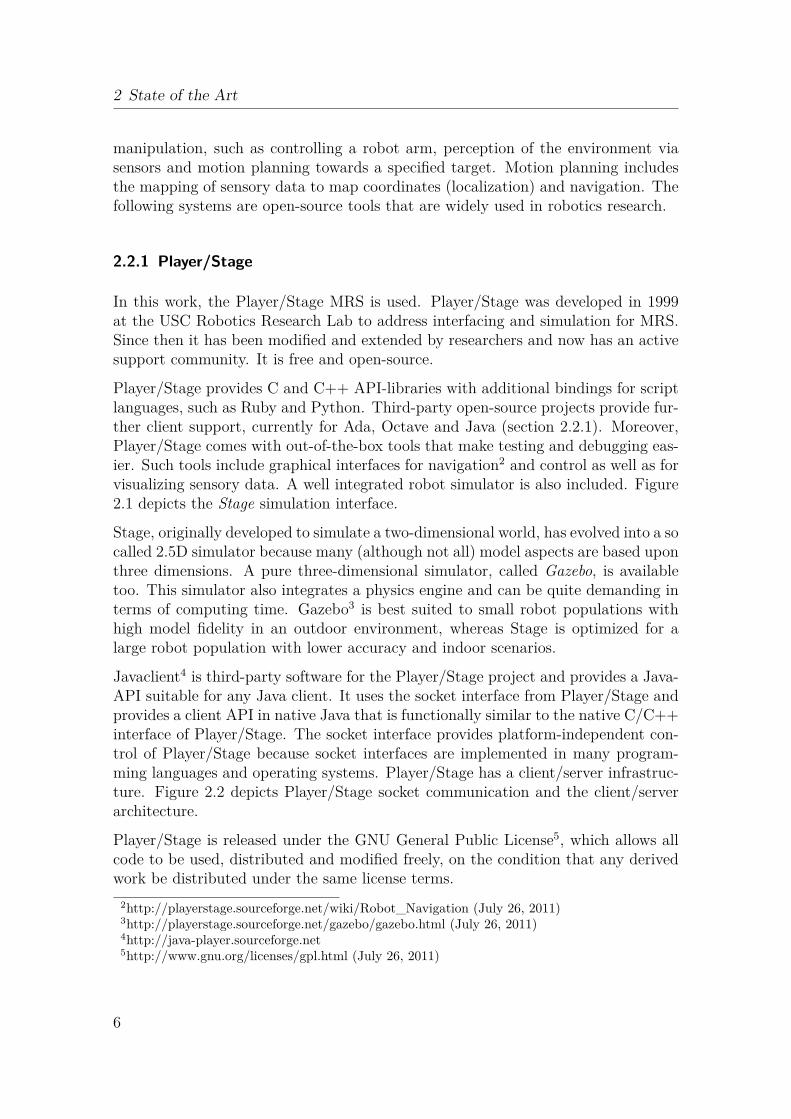
Player/Stage provides C and C++ API-libraries with additional bindings for scriptlanguages, such as Ruby and Python. Third-party open-source projects provide fur-ther client support, currently for Ada, Octave and Java (section 2.2.1). Moreover,Player/Stage comes with out-of-the-box tools that make testing and debugging eas-ier. Such tools include graphical interfaces for navigation2 and control as well as forvisualizing sensory data. A well integrated robot simulator is also included. Figure2.1 depicts the Stage simulation interface.
Stage, originally developed to simulate a two-dimensional world, has evolved into a socalled 2.5D simulator because many (although not all) model aspects are based uponthree dimensions. A pure three-dimensional simulator, called Gazebo, is availabletoo. This simulator also integrates a physics engine and can be quite demanding interms of computing time. Gazebo3 is best suited to small robot populations withhigh model fidelity in an outdoor environment, whereas Stage is optimized for alarge robot population with lower accuracy and indoor scenarios.
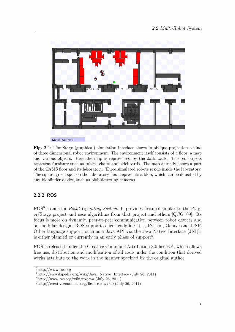
Javaclient4 is third-party software for the Player/Stage project and provides a Java-API suitable for any Java client. It uses the socket interface from Player/Stage andprovides a client API in native Java that is functionally similar to the native C/C++interface of Player/Stage. The socket interface provides platform-independent con-trol of Player/Stage because socket interfaces are implemented in many program-ming languages and operating systems. Player/Stage has a client/server infrastruc-ture. Figure 2.2 depicts Player/Stage socket communication and the client/serverarchitecture.
Player/Stage is released under the GNU General Public License5, which allows allcode to be used, distributed and modified freely, on the condition that any derivedwork be distributed under the same license terms.
2http://playerstage.sourceforge.net/wiki/Robot_Navigation (July 26, 2011)3http://playerstage.sourceforge.net/gazebo/gazebo.html (July 26, 2011)4http://java-player.sourceforge.net5http://www.gnu.org/licenses/gpl.html (July 26, 2011)
6
2.2 Multi-Robot System
Fig. 2.1: The Stage (graphical) simulation interface shows in oblique projection a kindof three dimensional robot environment. The environment itself consists of a floor, a mapand various objects. Here the map is represented by the dark walls. The red objectsrepresent furniture such as tables, chairs and sideboards. The map actually shows a partof the TAMS floor and its laboratory. Three simulated robots reside inside the laboratory.The square green spot on the laboratory floor represents a blob, which can be detected byany blobfinder device, such as blob-detecting cameras.
2.2.2 ROS
ROS6 stands for Robot Operating System. It provides features similar to the Play-er/Stage project and uses algorithms from that project and others [QCG+09]. Itsfocus is more on dynamic, peer-to-peer communication between robot devices andon modular design. ROS supports client code in C++, Python, Octave and LISP.Other language support, such as a Java-API via the Java Native Interface (JNI)7,is either planned or currently in an early phase of support8.
ROS is released under the Creative Commons Attribution 3.0 license9, which allowsfree use, distribution and modification of all code under the condition that derivedworks attribute to the work in the manner specified by the original author.
6http://www.ros.org7http://en.wikipedia.org/wiki/Java_Native_Interface (July 26, 2011)8http://www.ros.org/wiki/rosjava (July 26, 2011)9http://creativecommons.org/licenses/by/3.0 (July 26, 2011)
7
2 State of the Art
C++
Socket
Hardware
Robot
Network
Application
MRS
C++
...
...
Player
Server
Java
Java
ClientConfiguration
Drivers
Socket
Project Scope
Layer
Module
Control Flow
Fig. 2.2: Here a native Java application calls the MRS. Commands are sent through thesocket interface via a network (LAN or WLAN) to the Player server, which could be run-ning either locally or remotely. Finally the commands are sent to the locally connectedrobot hardware, e.g. the robot wheel motors. Arrows show the call direction. Instead ofusing Java, the application could be coded in C++ (or another MRS-supported program-ming language) and would use the appropriate bindings in the MRS client libraries.
2.2.3 Discussion
Player/Stage provides driver support for the hardware available at the TAMS lab-oratory. The reliable Pioneer series mobile robot hardware, from the MobileRobotsInc., is especially well supported. New or unsupported hardware can be integratedthrough Player/Stage’s modular plugin-driver architecture and experience and codecan be re-used from earlier research (section 2.4). Probably the most importantcurrent advantage of this MRS is its well supported and functional Java-API. ThisAPI can easily be integrated with multi-agent systems (section 2.3), such as theJava Agent Development Framework10 (JADE) or Jadex11.Other programming languages (such as C/C++ or Python, which are used by theROS project) can be integrated with Java code via JNI or Java Native Access12
(JNA). Although this augments the variety of usable programming languages, itstill has the disadvantage of being a non-native interface from the client languageperspective. This could introduce constraints on programming flexibility and main-tainability and could potentially introduce errors.Both Player/Stage and ROS support distributed Devices interacting within a net-work, serve as a kind of robot operating system and provide a Hardware AbstractionLayer (HAL).10http://jade.tilab.com11http://sourceforge.net/projects/jadex12http://en.wikipedia.org/wiki/Java_Native_Access (July 26, 2011)
8
2.3 Multi-Agent System
In this work the MRS Player/Stage has been chosen as a result of experience gainedwith it during preliminary work and because of its well supported Java-API.
2.3 Multi-Agent System
A multi-agent system is a software system providing a platform to implement, inte-grate and run agents.
An agent is anything that can be viewed as perceiving its environmentthrough sensors and acting upon that environment through effectors. Ahuman agent has eyes, ears, and other organs for sensors, and hands, legs,mouth, and other body parts for effectors. A robotic agent substitutescameras and infrared range finders for the sensors and various motorsfor the effectors. A software agent has encoded bit strings as its perceptsand actions. [RN03]
Of note is the frequent definition of a robot as a physical agent. Thus in relatedwork a physical robot is often called an agent when it acts autonomously to a certaindegree. That does not necessarily mean that in such scenarios a dedicated MAS hasbeen integrated.When it comes to software design, the question of why we use agents and not objectsarises (in the sense of object-oriented programming). Agents can be viewed as anevolution of programming methodology. Many properties of agents are also associ-ated with objects such as modularity and code reusability or message passing forinformation exchange. Nevertheless agents have some more advanced abilities. Forexample they are typically autonomous. Consequently, the mapping from percep-tions to actions relies not only on pre-defined knowledge but also upon experience.What is more, agents are normally dynamic: they do not just wait for messages ormethod invocations to perform an action but can invoke methods by themselves. Inother words, they have their own thread of execution.Agents are encapsulated within a software system, here called a platform, that starts,runs, and stops them and provides network services for distributing work acrossmultiple computers. A computer, here, can be plain, without special equipment, ordedicated, having particular attached hardware, such as the embedded computersintegrated within robots. Moreover the development of agents provides an adaptivesystem that handles high software complexity, scalability and modularity. Service-and goal-oriented modeling and flexible deployment are some of its advantages.Model Driven Architectures (MDA) and declarative programming are commonlyused for MAS applications.So an MAS consists of a platform and the agent code that together provide out-of-the-box capabilities for distributed systems. With the ideal agent-system thedeveloper would just pick the agents needed for a task and the agents would organize
9
2 State of the Art
themselves to achieve the goal. Another ideal approach would be an agent-systemthat could be given a task and the necessary agents would be selected automatically.There are lot of MAS platforms available today13. They can be classified broadlyas either middleware- or reasoning-oriented systems [BPL04]. Beside the functionalfocus, other aspects are also important in choosing the right software for a project.License conditions might enable the use or modification of the software without fees.Standards compliance, especially for communication protocols or interoperability,might be important depending upon the project goals. That the software has alarge supporting community or has been integrated in third-party projects gives anindication of its maturity. Last but not least, project oriented tools already includedmight change the selection in favor of other software.The MAS used in this work combines middleware and a reasoning-oriented layer.It is open-source and has a large user community. The preference for this softwarearises from its standards compliance and its design as an operating system indepen-dent application. In addition, basic tools for agent-debugging are included and theavailable local knowledge of the software provides for fast support.
2.3.1 Jadex
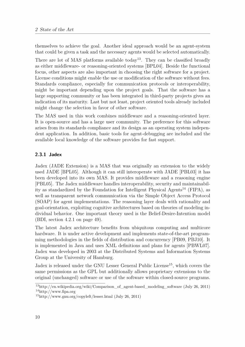
Jadex (JADE Extension) is a MAS that was originally an extension to the widelyused JADE [BPL05]. Although it can still interoperate with JADE [PBL03] it hasbeen developed into its own MAS. It provides middleware and a reasoning engine[PBL05]. The Jadex middleware handles interoperability, security and maintainabil-ity as standardized by the Foundation for Intelligent Physical Agents14 (FIPA), aswell as transparent network communication via the Simple Object Access Protocol(SOAP) for agent implementations. The reasoning layer deals with rationality andgoal-orientation, exploiting cognitive architectures based on theories of modeling in-dividual behavior. One important theory used is the Belief-Desire-Intention model(BDI, section 4.2.1 on page 49).The latest Jadex architecture benefits from ubiquitous computing and multicorehardware. It is under active development and implements state-of-the-art program-ming methodologies in the fields of distribution and concurrency [PB09, PBJ10]. Itis implemented in Java and uses XML definitions and plans for agents [PBWL07].Jadex was developed in 2003 at the Distributed Systems and Information SystemsGroup at the University of Hamburg.Jadex is released under the GNU Lesser General Public License15, which covers thesame permissions as the GPL but additionally allows proprietary extensions to theoriginal (unchanged) software or use of the software within closed-source programs.13http://en.wikipedia.org/wiki/Comparison_of_agent-based_modeling_software (July 26, 2011)14http://www.fipa.org15http://www.gnu.org/copyleft/lesser.html (July 26, 2011)
10
2.4 Preliminary Work
2.4 Preliminary Work
In an earlier project [RG10] we used Player/Stage to implement a ball-trackingmobile robot. A Pioneer-2DX robot with on-board sonar, laser and omni-directionalcamera served as the hardware (the mobile robot hardware platform can be seen infigure 3.2 on page 17). With a wall-following exploration algorithm and the sonar,laser and camera data, its goal was to look for a small pink ball in its environment.Once detected the robot headed towards the ball while continuously tracking it. Theproject provided practical experience with a robot platform and with mobile robothardware that will be relied upon by this work.
2.5 Related Work
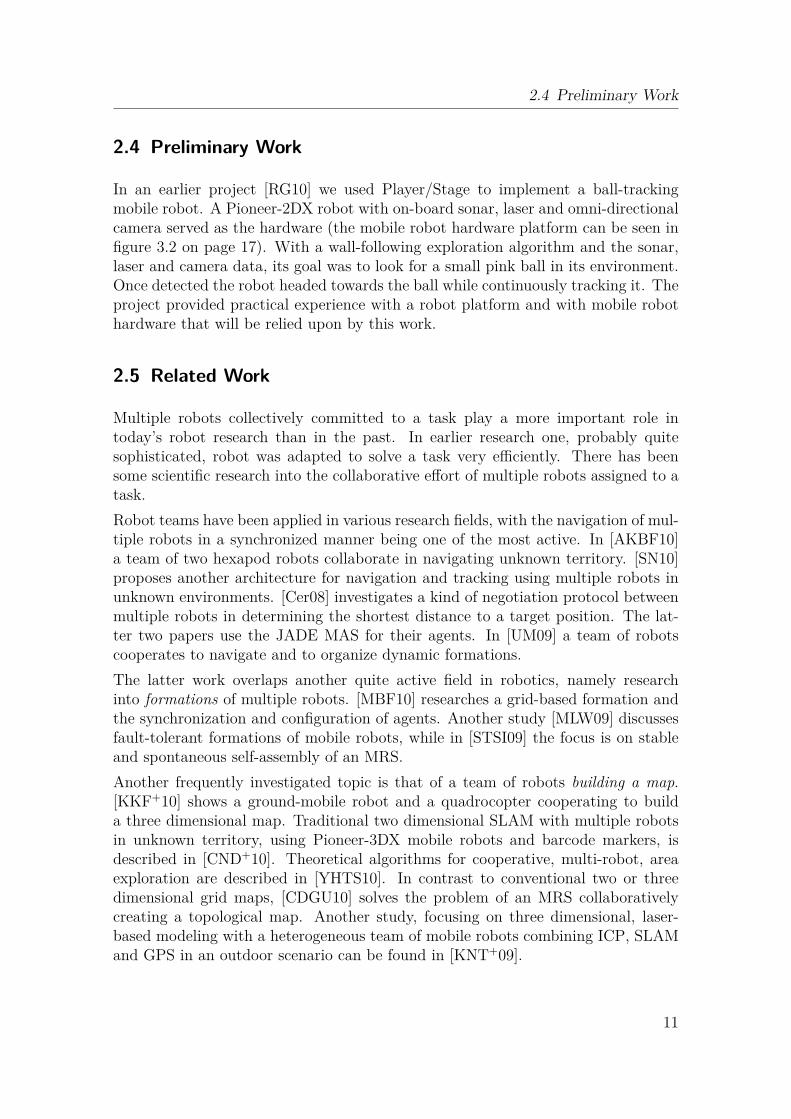
Multiple robots collectively committed to a task play a more important role intoday’s robot research than in the past. In earlier research one, probably quitesophisticated, robot was adapted to solve a task very efficiently. There has beensome scientific research into the collaborative effort of multiple robots assigned to atask.Robot teams have been applied in various research fields, with the navigation of mul-tiple robots in a synchronized manner being one of the most active. In [AKBF10]a team of two hexapod robots collaborate in navigating unknown territory. [SN10]proposes another architecture for navigation and tracking using multiple robots inunknown environments. [Cer08] investigates a kind of negotiation protocol betweenmultiple robots in determining the shortest distance to a target position. The lat-ter two papers use the JADE MAS for their agents. In [UM09] a team of robotscooperates to navigate and to organize dynamic formations.The latter work overlaps another quite active field in robotics, namely researchinto formations of multiple robots. [MBF10] researches a grid-based formation andthe synchronization and configuration of agents. Another study [MLW09] discussesfault-tolerant formations of mobile robots, while in [STSI09] the focus is on stableand spontaneous self-assembly of an MRS.Another frequently investigated topic is that of a team of robots building a map.[KKF+10] shows a ground-mobile robot and a quadrocopter cooperating to builda three dimensional map. Traditional two dimensional SLAM with multiple robotsin unknown territory, using Pioneer-3DX mobile robots and barcode markers, isdescribed in [CND+10]. Theoretical algorithms for cooperative, multi-robot, areaexploration are described in [YHTS10]. In contrast to conventional two or threedimensional grid maps, [CDGU10] solves the problem of an MRS collaborativelycreating a topological map. Another study, focusing on three dimensional, laser-based modeling with a heterogeneous team of mobile robots combining ICP, SLAMand GPS in an outdoor scenario can be found in [KNT+09].
11
2 State of the Art
Other areas of research concentrate on the problems of task allocation and sub-division, which arise when a task is to be split into sub-tasks for each robot. [RAB09]uses a box pushing scenario in a heterogeneous MRS, while a framework for multi-robot coordination and task allocation is proposed in [SC09]. Other research sug-gests another scenario: a number of mobile robots are combined to find, collect anddrop trash into dustbins to clean the floor [MAC97, BBC+95].
An important aspect of concurrent and autonomous software systems (with agentsand robots) is the design of software such that it remains efficient, easy to maintainand re-usable. [BRA94] investigates how efficient communication in a multi-agentrobotic system can increase overall performance, whereas [TvS10] focuses on modularand re-usable software in autonomous robot systems. A system with intelligentpower management for teams of robots is introduced in [KDP09].
A traditional Artificial Intelligence (AI) topic, reinforcement learning in cooperativeMRS, is described in [SMKR09]. Finally, an increasing area of motivation and effort,the field of mixed reality simulation, was studied for mobile robots in [CMW09].
2.6 Advantages of a Combined MAS and MRS Platform
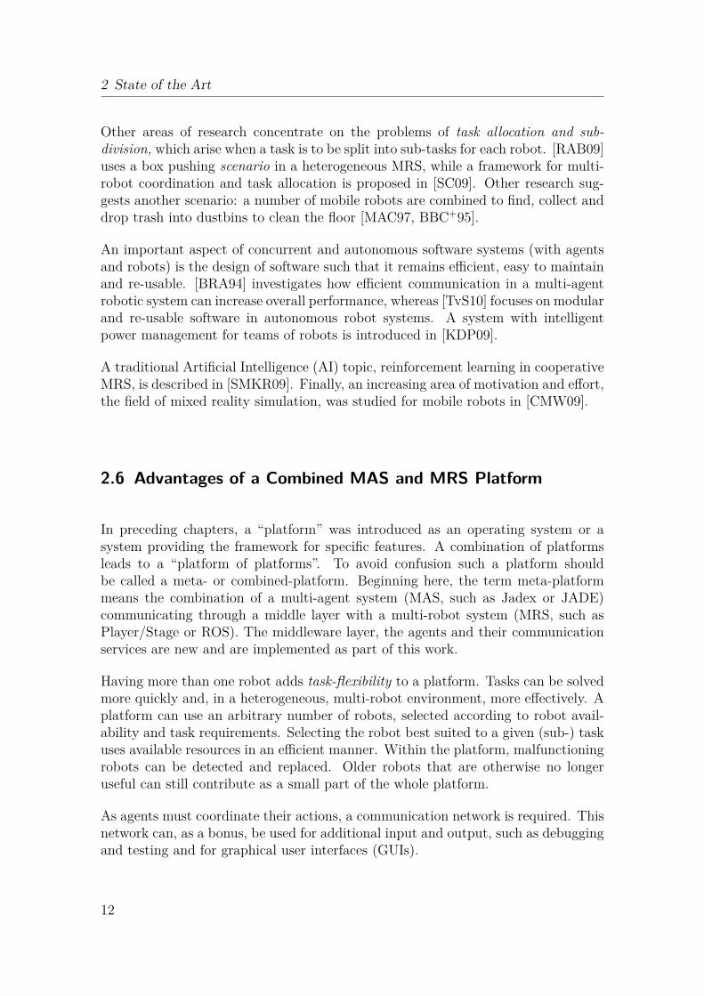
In preceding chapters, a “platform” was introduced as an operating system or asystem providing the framework for specific features. A combination of platformsleads to a “platform of platforms”. To avoid confusion such a platform shouldbe called a meta- or combined-platform. Beginning here, the term meta-platformmeans the combination of a multi-agent system (MAS, such as Jadex or JADE)communicating through a middle layer with a multi-robot system (MRS, such asPlayer/Stage or ROS). The middleware layer, the agents and their communicationservices are new and are implemented as part of this work.
Having more than one robot adds task-flexibility to a platform. Tasks can be solvedmore quickly and, in a heterogeneous, multi-robot environment, more effectively. Aplatform can use an arbitrary number of robots, selected according to robot avail-ability and task requirements. Selecting the robot best suited to a given (sub-) taskuses available resources in an efficient manner. Within the platform, malfunctioningrobots can be detected and replaced. Older robots that are otherwise no longeruseful can still contribute as a small part of the whole platform.
As agents must coordinate their actions, a communication network is required. Thisnetwork can, as a bonus, be used for additional input and output, such as debuggingand testing and for graphical user interfaces (GUIs).
12
2.7 Summary
2.7 Summary
In this chapter we have defined multi-robot and multi-agent systems and have de-scribed the features they typically provide. We have discussed commonly used,open-source software projects providing these features, summarized preliminary andrelated work and introduced recent, related, research into this topic. Finally theadvantages of a combined MAS and MRS platform have been presented.
13

2 State of the Art
14
Approach
33.1 Introduction
This chapter describes the core work of this thesis. The platform developed will beintroduced and described in detail. Explanations of the concept, the architecture,the detailed design and the implementation will shed light on the ideas behind thiswork.
3.2 Goals
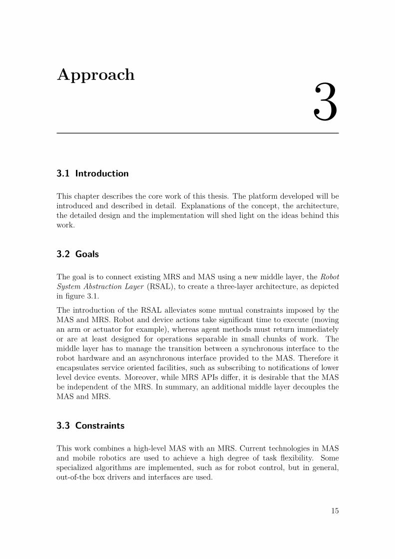
The goal is to connect existing MRS and MAS using a new middle layer, the RobotSystem Abstraction Layer (RSAL), to create a three-layer architecture, as depictedin figure 3.1.
The introduction of the RSAL alleviates some mutual constraints imposed by theMAS and MRS. Robot and device actions take significant time to execute (movingan arm or actuator for example), whereas agent methods must return immediatelyor are at least designed for operations separable in small chunks of work. Themiddle layer has to manage the transition between a synchronous interface to therobot hardware and an asynchronous interface provided to the MAS. Therefore itencapsulates service oriented facilities, such as subscribing to notifications of lowerlevel device events. Moreover, while MRS APIs differ, it is desirable that the MASbe independent of the MRS. In summary, an additional middle layer decouples theMAS and MRS.
3.3 Constraints
This work combines a high-level MAS with an MRS. Current technologies in MASand mobile robotics are used to achieve a high degree of task flexibility. Somespecialized algorithms are implemented, such as for robot control, but in general,out-of-the box drivers and interfaces are used.
15
3 Approach
UI
Control Flow
Driver
Project Scope
Layer
Module
Multi−Agent System
Robot System Abstraction Layer
Multi−Robot System
Fig. 3.1: The overall meta-platform architecture shows three layers. An existing MASencapsulates agents and related services. The user has access to the platform using theMAS user interface through which agents can be started and stopped. Multiple agentscontributing to a task are managed through scenario selection. The MRS layer containsthe robot hardware related code and drivers. The new middle layer, RSAL, negotiatesbetween these layers, manages functional hardware related code, provides object-orientedaccess to robots, their devices and behaviors and thus decouples the MAS and MRS.
An MAS is assumed to provide certain features:• that a sample task can be described by the MAS tools and that the requireddefinitions (such as of agents) can be created conveniently within the frame-work;• that complex tasks can be divided into sub-tasks and distributed to multiple
agents;• and that distributed agents can use the MAS network communication layer to
exchange data.The MRS also has to fulfill some minimal requirements. The most important featureis path planning, although there might be use-cases where this is not needed. Theliteral meaning of this is that the robot is able to move from its current position to agiven target position. Path planning therefore involves several sub-tasks, especiallythe ability to localize on a map using sensors, such as laser or sonar rangers. Knowingits position, the robot should be able to plan a valid trajectory through unoccupiedspace (floors and rooms) and not hit anything, including both static objects (those onthe map) and dynamic obstacles (those not on the map, such as people, furnitureor other robots). Last but not least, the MRS has to provide the drivers for allhardware, such as the robot, sensors and effectors.Some other constraints also exist, especially to the practical demonstration: thetypes and numbers of robot hardware available at the TAMS laboratory are limited,and as the algorithms used for robot control are part of the MRS, they rely uponthe current driver implementations.
16
3.3 Constraints
3.3.1 Robot Hardware
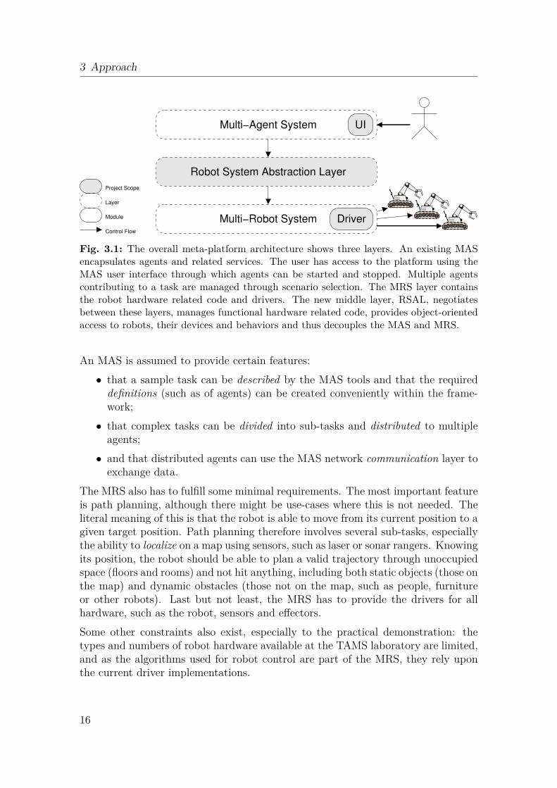
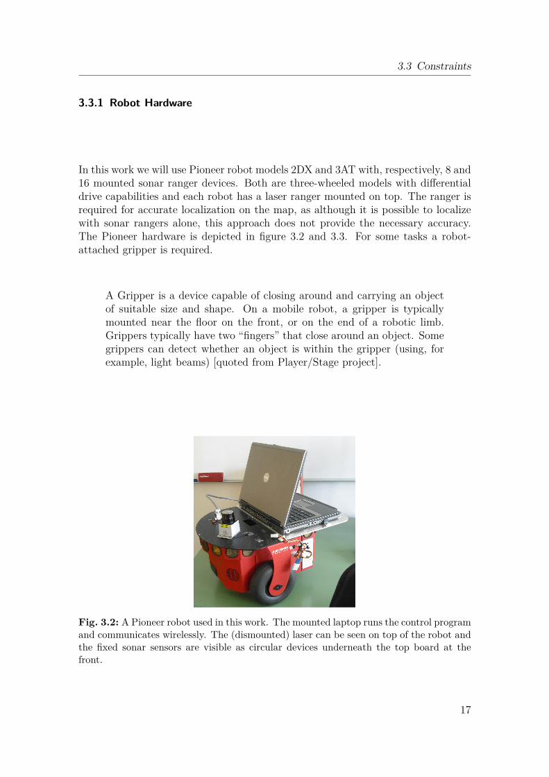
In this work we will use Pioneer robot models 2DX and 3AT with, respectively, 8 and16 mounted sonar ranger devices. Both are three-wheeled models with differentialdrive capabilities and each robot has a laser ranger mounted on top. The ranger isrequired for accurate localization on the map, as although it is possible to localizewith sonar rangers alone, this approach does not provide the necessary accuracy.The Pioneer hardware is depicted in figure 3.2 and 3.3. For some tasks a robot-attached gripper is required.
A Gripper is a device capable of closing around and carrying an objectof suitable size and shape. On a mobile robot, a gripper is typicallymounted near the floor on the front, or on the end of a robotic limb.Grippers typically have two “fingers” that close around an object. Somegrippers can detect whether an object is within the gripper (using, forexample, light beams) [quoted from Player/Stage project].
Fig. 3.2: A Pioneer robot used in this work. The mounted laptop runs the control programand communicates wirelessly. The (dismounted) laser can be seen on top of the robot andthe fixed sonar sensors are visible as circular devices underneath the top board at thefront.
17
3 Approach
� �1 d r i v e r2 (3 name "p2os"4 prov ides [ "odometry:::position2d:0" "sonar:0" "power:0"
"gripper:::gripper:0" "lift:::actarray:0" "dio:0" "audio:0" ]5 port "/dev/ttyS0"6 )� �
List. 3.1: This driver configuration for the Player/Stage MRS invokes the built-in p2osdriver. Its purpose is to provide access to the interfaces of the Pioneer robot hardware.Here for instance, several features of the Pioneer-2DX are provided: the odometer andmotor (both via the position2d interface), sonars, battery power, gripper (if equipped),the lift to which the optional gripper is attached, digital input and output for opticalgripper sensors and an audio interface.
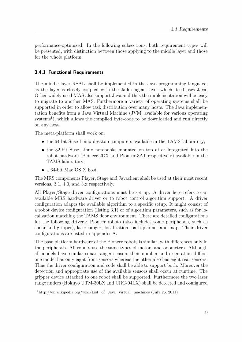
Fig. 3.3: Three robots used for the real-world demonstration: from left to right, a Pioneer-2DX, another 2DX with a front-gripper attached and a Pioneer-3AT with an embeddedcomputer.
3.3.2 MRS Driver
In order to use robot hardware, a device-specific driver must be available to theMRS. The Pioneer robots are supported by the Player/Stage p2os driver, whichsupports the Pioneer robot capabilities, including those of peripheral devices suchas an odometer, gripper or sonar ranger. In listing 3.1 the driver configuration usedfor a Pioneer-2DX is shown.
3.4 Requirements
Requirements can be functional or non-functional. Function requirements indicateessential demands that are specified in detail, such as that the robot shall have amaximum weight of fifteen kilograms. Non-functional requirements specify prop-erties that cannot be given accurately, for example that robot control has to be
18
3.4 Requirements
performance-optimized. In the following subsections, both requirement types willbe presented, with distinction between those applying to the middle layer and thosefor the whole platform.
3.4.1 Functional Requirements
The middle layer RSAL shall be implemented in the Java programming language,as the layer is closely coupled with the Jadex agent layer which itself uses Java.Other widely used MAS also support Java and thus the implementation will be easyto migrate to another MAS. Furthermore a variety of operating systems shall besupported in order to allow task distribution over many hosts. The Java implemen-tation benefits from a Java Virtual Machine (JVM, available for various operatingsystems1), which allows the compiled byte-code to be downloaded and run directlyon any host.The meta-platform shall work on:• the 64-bit Suse Linux desktop computers available in the TAMS laboratory;• the 32-bit Suse Linux notebooks mounted on top of or integrated into the
robot hardware (Pioneer-2DX and Pioneer-3AT respectively) available in theTAMS laboratory;• a 64-bit Mac OS X host.
The MRS components Player, Stage and Javaclient shall be used at their most recentversions, 3.1, 4.0, and 3.x respectively.All Player/Stage driver configurations must be set up. A driver here refers to anavailable MRS hardware driver or to robot control algorithm support. A driverconfiguration adapts the available algorithm to a specific setup. It might consist ofa robot device configuration (listing 3.1) or of algorithm parameters, such as for lo-calization matching the TAMS floor environment. There are detailed configurationsfor the following drivers: Pioneer robots (also includes some peripherals, such assonar and gripper), laser ranger, localization, path planner and map. Their driverconfigurations are listed in appendix A.The base platform hardware of the Pioneer robots is similar, with differences only inthe peripherals. All robots use the same types of motors and odometers. Althoughall models have similar sonar ranger sensors their number and orientation differs:one model has only eight front sensors whereas the other also has eight rear sensors.Thus the driver configuration and code shall be able to support both. Moreover thedetection and appropriate use of the available sensors shall occur at runtime. Thegripper device attached to one robot shall be supported. Furthermore the two laserrange finders (Hokuyo UTM-30LX and URG-04LX) shall be detected and configured
1http://en.wikipedia.org/wiki/List_of_Java_virtual_machines (July 26, 2011)
19
3 Approach
at runtime. In order to provide accurate localization, a map of the TAMS floor mustbe created with a fidelity of at least 0.05 meters per pixel. Robot navigation requiresthat a set of appropriate Player/Stage drivers be set up for localization and for bothlocal and global navigation. It also requires a map driver that must manage theTAMS floor grid map.The task of robot navigation is typically divided into local and global path planning,as described in the following paragraphs2.
Path planning, sometimes called “Motion Planning”, is the act of findinga path to go from location A to B. [...] There are many approaches tosolving path planning, but usually it involves a local and global pathplanner.A global path planner usually generates a low-resolution high-level pathfrom A to B, avoiding large obstacles and dealing with navigation aroundthe arena. This is analogous to the path Google Maps might give youfrom home to a park. Local path planning usually gives a high-resolutionlow-level path only over a segment from global path A to B, avoidingsmall obstacles and dealing with motion planning: angles of turn, ap-propriate velocities, etc. This is analogous to choosing how fast to turnyour car when moving around traffic while on your Google Maps path.Path planning is a major topic in Computer Science, Electrical Engi-neering, and Mechanical Engineers. Many topics that serve as the basisfor path planning include graph theory, geometric algorithms, potentialfields, etc. Path planning is known to be an algorithmically intensiveproblem to solve.
In robotics, the coordinate systems in which positions are defined are called coordi-nate frames. Frames can relate to each other and coordinate transformations enablea position defined in one frame to be expressed as coordinates in a different frame.When referring to a position it is always related to some frame of reference. Anabsolute and fixed coordinate system is called the global or world frame.To elaborate on the requirements for the path planning component, there follows ashort description of how path planning is typically implemented.A path planner typically accepts a target position specified in global coordinates.As the robot’s frame of reference typically differ from the global one, the targetcoordinates must be transformed to the local frame. Planning is focused on a directtrajectory from the current position to the target, which is assumed to be in the lineof sight. To avoid dynamic obstacles, an avoidance component is integrated.In contrast to a local path planner, a global one parses the static map for permanentobstacles, such as walls and divides the planar space into occupied and free grid cells.
2quoted from http://psurobotics.org/wiki (July 11, 2011)
20
3.4 Requirements
Cells that are close to an obstacle are assigned a higher cost than cells in open space.According to this grid and to additional algorithm parameters, such as the minimalallowed distance to an obstacle, the final path will be planned.
A successful trajectory consists of a start, a goal, intermediate goals and intermediatepaths. Intermediate goals lie in the line of sight of adjacent ones and are given tothe local path planner. Upon completion of an intermediate goal, the local planneris assigned the next one and so on. Local and global path planners must be tuned(by parameter tuning) in order to achieve robust overall performance. For examplethis affects (intermediate) goal position deviation. The permitted planar deviation(from the real position) must always be more restrictive for the local planner thanfor the global planner. This avoids a blocking situation where the local planner issatisfied with the robot position whereas the global planner is waiting endlessly fora more accurate position to be reached.
A variety of local path planning algorithms is available and each has its advantages.Their comparison is not in the scope of this work. An overview of planning algo-rithms can be found in [LaV06, SN04]. Algorithms implemented as Player/Stagedrivers are the Vector Field Histogram (VFH), the Nearness Diagram (ND) andthe Smoothed Nearness Diagram (SND). The VFH algorithm has been chosen forthis work due to its proven practical robustness with the Pioneer robots and itsefficient path planning. A global path planning algorithm has been implementedwith the Wavefront driver, which is delivered with the Player/Stage software andmust be configured to suit the project. The meta-platform shall support all fourpath planning drivers.
To efficiently localize the robot within the map the Adaptive Monte Carlo Local-ization (AMCL) algorithm has to be supported. A maximum deviation of 30 cen-timeters from the real position compared to the localization hypothesis shall beachieved. The Monte Carlo algorithm is based on a probabilistic particle filter. Itis capable of using multiple sonar rangers or one laser ranger in combination withodometer values to calculate the robot’s most probable position. While this positionhas the highest probability, other hypotheses are possible and are tracked in par-allel. After initialization, all particles are randomly distributed with equal weight.When processing new sensory data, each particle position is matched against theretrieved sensor data and assigned a new weight according to its probability. Theadvantage of the algorithm is its dynamic assignment of particle counts. The moreparticles that point to the same hypothesis, the more probable the hypothesis andthe fewer particles are needed. In contrast, if all current hypotheses are improbable,more particles will be generated and tracked. Once a suitable position estimate hasbeen found, further position updates take the position history into account. Thusthe algorithm requires very few resources when iteratively updating the positionestimate.
21
3 Approach
3.4.2 Non-Functional Requirements
Robot services, such as localization, have to be available early in the start up pro-cess, so that higher layers can access relevant data. For example, the initial posehypothesis is the first estimated position from the localization component. It iseither obtained automatically, by mapping sensor values in a particle-based local-ization algorithm, or, if that fails, it is set by the user placing an icon on a map-likeinterface. This is important, as higher layers might broadcast their initial state toother participants and rely on early receipt of correct data.Due to high innovation rates for robot hardware and drivers, the platform shallallow for the easy configuration of different devices. It must be possible to supporthardware other than that described in this work without major architectural changesto the concept of a meta-platform.The platform ensures that operations are started but does not guarantee their com-pletion (as they might be dependent upon the hardware state). Nevertheless op-eration failure and success shall be notified to the calling application, typically anagent.The user is likely to choose a different MAS and MRS from those described in thiswork. Therefore it shall be easy for the user to adapt the meta-platform for theirMAS and MRS of choice.The platform shall be operating system independent and compatible with today’sstandard PC environments.Software components shall be designed for re-use in different use-cases.The platform shall provide a graphical user interface to start, stop and modifyscenarios.A robot simulator shall be provided to allow the platform to be exercised withoutreal robot hardware.The hardware might enter an erroneous state and the software shall therefore provideerror prevention and recovery facilities.The software shall be adaptable to new robots, devices and behaviors.As another software layer necessarily introduces more code, it shall introduce thesmallest possible delays and shall be performance optimized. The latter requirementalso applies to all driver configurations.
3.4.3 Performance Requirements
The system shall be optimized for typical use-cases. Furthermore the requirementsfor each layer vary. The execution overhead introduced by the MAS layer cannot
22
3.5 System Architecture
normally be changed. Such overheads include delays introduced by non-user code,such as agent creation and destruction, task management and distributed commu-nication. However the performance of agent code implemented by the user variesaccording to the task and must be optimized. Agent designs shall follow the designguidelines given by the multi-agent system (Jadex in this case).
An agent must typically remain responsive to the system at all times and musttherefore split its actual task into small steps of work. In Jadex terminology, anagent performs tasks in steps called IComponentSteps that are efficiently plannedand executed by the Jadex scheduler. In order to promote responsiveness, tasksshall be asynchronous wherever possible. Hence an execution step shall either bevery short or it shall be capable of subdivision into smaller steps. Failing that, atask shall provide a callback or future interface so that an agent can set the taskrunning asynchronously and receive notification when it finishes. This releases theagent’s resources for other activities. As the agent will typically use robot servicesfrom the RSAL, these services have to be designed in such a manner.
The RSAL consists mainly of robots, behaviors and devices. Devices are hardwaredependent and thus have to fulfill real-time requirements. A laser ranger may deliverrange values periodically (for example at 10 Hertz) and the appropriate softwaredevice must respond at this rate. Other hardware might require servicing at differentrates. As a robot can have many devices their servicing must be very fast.
As described, requirements differ from top to bottom of the architectural model.Each layer has to fulfill its own (performance) requirements. Moreover each layerhas to contribute to the overall scalability requirement of the meta-platform, asdefined in section 3.5.
3.5 System Architecture
The meta-platform consists of three layers. The user interacts with the top-mostlayer, the MAS. More specifically the GUI is provided by Jadex3, the MAS in thecurrent implementation. Jadex provides a clear and efficient interface for startingscenarios and individual agents and for passing the necessary arguments. The argu-ments differ according to whether an agent or a scenario is started. When startingan agent, the actual type of agent is also significant. The following arguments aretypically passed when creating an agent via the Jadex GUI:
• Host: The host field is a string specifying the networked computer on which thePlayer server is running. It can take a name resolved via the Domain NameService (DNS) or an Internet Protocol (IP) address. This field defaults tolocalhost and need only be changed when the agent and the robot controlling
3Screenshot at http://jadex-agents.informatik.uni-hamburg.de/xwiki (July 11, 2011)
23
3 Approach
computer are at different addresses. For example, this is the case when allagents run on a central computer rather than on the robot local computer.• Port: The port field contains the computer port (of integer type) on which
the Player server is listening. It defaults to the Player standard port 6665.Again, this is only needed when the agent is not running locally on the robotcomputer.• (Robot) Identifier: robId is the network-unique numerical identifier of the
robot. This field is used to distinguish between robots taking part in a scenarioand to map them into a virtual environment.• (Device) Index: It is possible to have multiple sonar, laser or other devices
on the same host/port combination. In this case the devIndex can be used todefine the appropriate device tuple, where the tuple is a combination of certaindevices provided to the agent. The order of tuple fields must be consistent,such as sonar first and laser second. This numerical field is only needed whenrunning multiple agents on a central computer and corresponds to the Device(class) index field (figure 3.18).• Initial Position: This x, y and angle tuple, consisting of double-precision val-
ues, optionally specifies the robot’s initial position. The angle field definesthe robot initial (front) orientation. The tuple defaults to (0,0,0) and anydifferent values (if set) modify the robot localization device accordingly. Theunits are: meter (x), meter (y) and degree (angle). When the default value iskept (the tuple is not set) the robot position will be estimated using the laserranger and odometer readings. This tuple typically remains unset and thelocalization device automatically estimates the initial position. Nevertheless,if position estimation repeatedly fails, setting the tuple helps to correct therobot’s initial position. Moreover setting this field affects the robot proxy ina virtual environment, if any is available, as it sets the proxy robot directly tothat position.• Laser: This boolean flag can be used to disable the laser, which is normally
enabled. This affects robot wall-following and obstacle avoidance but does notaffect robot localization.• Simulation: Another boolean flag that is used to disable automatic searching
for a simulation environment on the network (see section 3.6.2.2 on page 35).Scenario arguments differ from those of agents. Typically a scenario does not needto be given an argument as fixed arguments are configured internally for each agent.Nevertheless a scenario typically has several configurations that can differ in thenumber of robots taking part or in the choice of virtual, real or mixed reality envi-ronments.Note that although the Player/Stage MRS has a built-in robot navigation GUI thatcan observe current plans and waypoints, the typical user interface is the MAS.
24
3.5 System Architecture
The MAS includes agents that will be started according to the scenario. Additionalagent-related components, such as services, are also included in the MAS layer.Agents call robot facilities from the RSAL. A robot can be controlled using itsexternal interface or using interfaces to attached devices, such as a planner devicefor navigation.
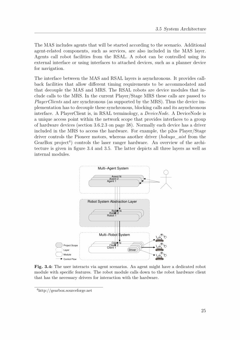
The interface between the MAS and RSAL layers is asynchronous. It provides call-back facilities that allow different timing requirements to be accommodated andthat decouple the MAS and MRS. The RSAL robots are device modules that in-clude calls to the MRS. In the current Player/Stage MRS these calls are passed toPlayerClients and are synchronous (as supported by the MRS). Thus the device im-plementation has to decouple these synchronous, blocking calls and its asynchronousinterface. A PlayerClient is, in RSAL terminology, a DeviceNode. A DeviceNode isa unique access point within the network scope that provides interfaces to a groupof hardware devices (section 3.6.2.3 on page 38). Normally each device has a driverincluded in the MRS to access the hardware. For example, the p2os Player/Stagedriver controls the Pioneer motors, whereas another driver (hokuyo_aist from theGearBox project4) controls the laser ranger hardware. An overview of the archi-tecture is given in figure 3.4 and 3.5. The latter depicts all three layers as well asinternal modules.
Robot N
Client N
Agent N
DriverClient 2
Robot 2
Agent 2
DriverProject Scope
Layer
Module
Control Flow
Agent 1
Multi−Agent System
Multi−Robot System
Client 1
Robot 1
Robot System Abstraction Layer
Driver
Fig. 3.4: The user interacts via agent scenarios. An agent might have a dedicated robotmodule with specific features. The robot module calls down to the robot hardware clientthat has the necessary drivers for interaction with the hardware.
4http://gearbox.sourceforge.net
25
3 Approach
Control Flow
Client
Server
Project Scope
Layer
Module
Robot 1
Device BDevice A
Agent 1
Driver
Robot System Abstraction Layer
Multi−Robot System
Service A
Service B
Multi−Agent System
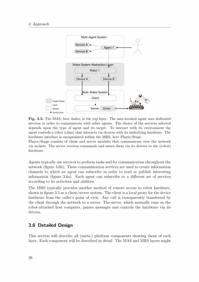
Fig. 3.5: The MAS, here Jadex, is the top layer. The user-invoked agent uses dedicatedservices in order to communicate with other agents. The choice of the services selecteddepends upon the type of agent and its target. To interact with its environment theagent controls a robot (class) that interacts via devices with its underlying hardware. Thehardware interface is encapsulated within the MRS, here Player/Stage.Player/Stage consists of client and server modules that communicate over the networkvia sockets. The server receives commands and issues them via its drivers to the (robot)hardware.
Agents typically use services to perform tasks and for communication throughout thenetwork (figure 3.6b). These communication services are used to create informationchannels to which an agent can subscribe in order to read or publish interestinginformation (figure 3.6a). Each agent can subscribe to a different set of servicesaccording to its activities and abilities.The MRS typically provides another method of remote access to robot hardware,shown in figure 3.5 as a client/server system. The client is a local proxy for the devicehardware from the caller’s point of view. Any call is transparently transferred bythe client through the network to a server. The server, which normally runs on therobot-attached host computer, parses messages and controls the hardware via itsdrivers.
3.6 Detailed Design
This section will describe all (meta-) platform components showing those of eachlayer. Each component will be described in detail. The MAS and MRS layers might
26
3.6 Detailed Design
Agent N
Service N
Agent 2
Service 2
Services
Publish/Subscribe
Agent 1
Service 1
(a)
Services
Service 1
Agent 1 Agent 2
(b)
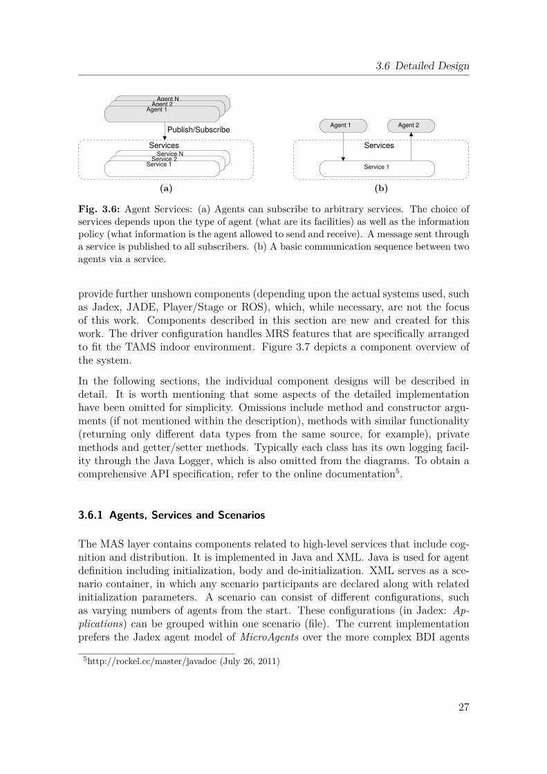
Fig. 3.6: Agent Services: (a) Agents can subscribe to arbitrary services. The choice ofservices depends upon the type of agent (what are its facilities) as well as the informationpolicy (what information is the agent allowed to send and receive). A message sent througha service is published to all subscribers. (b) A basic communication sequence between twoagents via a service.
provide further unshown components (depending upon the actual systems used, suchas Jadex, JADE, Player/Stage or ROS), which, while necessary, are not the focusof this work. Components described in this section are new and created for thiswork. The driver configuration handles MRS features that are specifically arrangedto fit the TAMS indoor environment. Figure 3.7 depicts a component overview ofthe system.
In the following sections, the individual component designs will be described indetail. It is worth mentioning that some aspects of the detailed implementationhave been omitted for simplicity. Omissions include method and constructor argu-ments (if not mentioned within the description), methods with similar functionality(returning only different data types from the same source, for example), privatemethods and getter/setter methods. Typically each class has its own logging facil-ity through the Java Logger, which is also omitted from the diagrams. To obtain acomprehensive API specification, refer to the online documentation5.
3.6.1 Agents, Services and Scenarios
The MAS layer contains components related to high-level services that include cog-nition and distribution. It is implemented in Java and XML. Java is used for agentdefinition including initialization, body and de-initialization. XML serves as a sce-nario container, in which any scenario participants are declared along with relatedinitialization parameters. A scenario can consist of different configurations, suchas varying numbers of agents from the start. These configurations (in Jadex: Ap-plications) can be grouped within one scenario (file). The current implementationprefers the Jadex agent model of MicroAgents over the more complex BDI agents
5http://rockel.cc/master/javadoc (July 26, 2011)
27
3 Approach
Test
Java
XML
Java
MRS specific
MRS
RSAL
MAS
Map
Data
Behavior
Agent
Service
Scenario
Robot
Driver Configuration
Simulation
Device
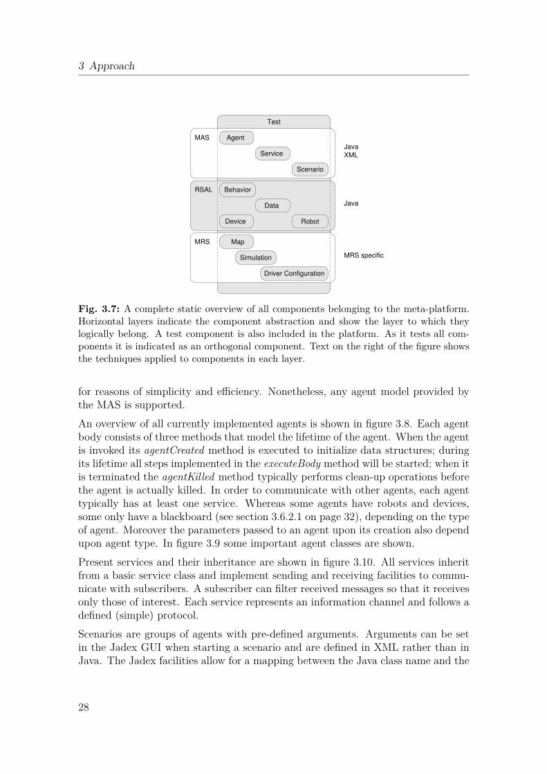
Fig. 3.7: A complete static overview of all components belonging to the meta-platform.Horizontal layers indicate the component abstraction and show the layer to which theylogically belong. A test component is also included in the platform. As it tests all com-ponents it is indicated as an orthogonal component. Text on the right of the figure showsthe techniques applied to components in each layer.
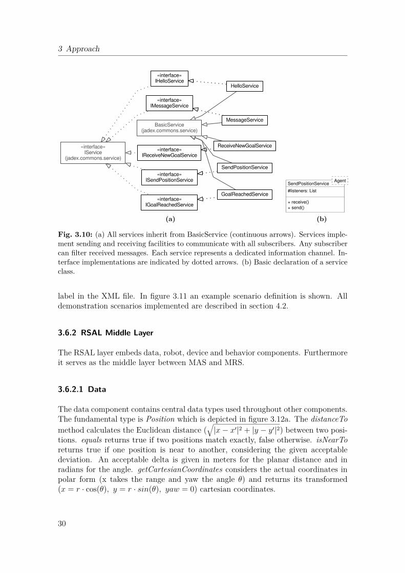
for reasons of simplicity and efficiency. Nonetheless, any agent model provided bythe MAS is supported.An overview of all currently implemented agents is shown in figure 3.8. Each agentbody consists of three methods that model the lifetime of the agent. When the agentis invoked its agentCreated method is executed to initialize data structures; duringits lifetime all steps implemented in the executeBody method will be started; when itis terminated the agentKilled method typically performs clean-up operations beforethe agent is actually killed. In order to communicate with other agents, each agenttypically has at least one service. Whereas some agents have robots and devices,some only have a blackboard (see section 3.6.2.1 on page 32), depending on the typeof agent. Moreover the parameters passed to an agent upon its creation also dependupon agent type. In figure 3.9 some important agent classes are shown.Present services and their inheritance are shown in figure 3.10. All services inheritfrom a basic service class and implement sending and receiving facilities to commu-nicate with subscribers. A subscriber can filter received messages so that it receivesonly those of interest. Each service represents an information channel and follows adefined (simple) protocol.Scenarios are groups of agents with pre-defined arguments. Arguments can be setin the Jadex GUI when starting a scenario and are defined in XML rather than inJava. The Jadex facilities allow for a mapping between the Java class name and the
28
3.6 Detailed Design
BlobAgent
CollectAgent
ConsoleAgent DispersionAgent
EscapeAgent
ExploreAgent
FollowAgent
MasterAgent
NavAgent
SwarmAgentViewAgent
WallfollowAgent
MicroAgent(jadex.micro)
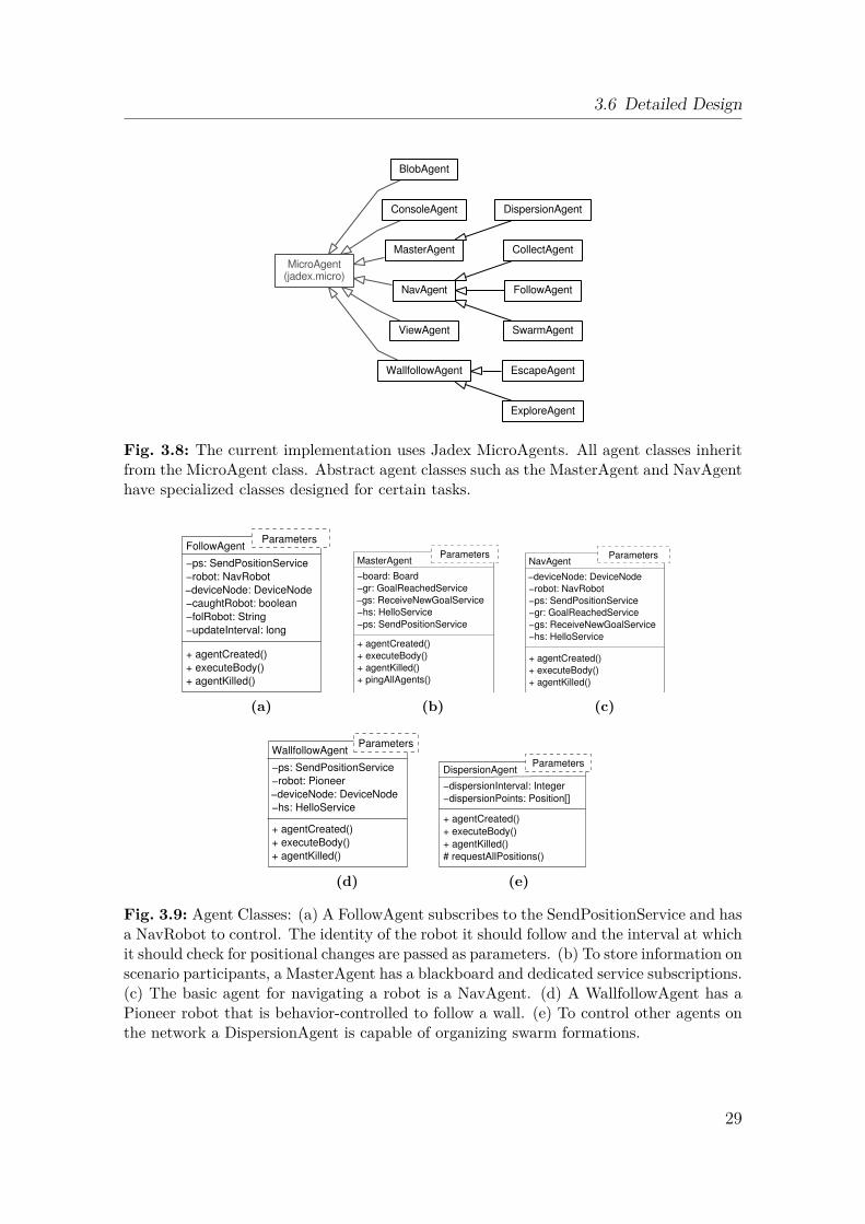
Fig. 3.8: The current implementation uses Jadex MicroAgents. All agent classes inheritfrom the MicroAgent class. Abstract agent classes such as the MasterAgent and NavAgenthave specialized classes designed for certain tasks.
−deviceNode: DeviceNode
+ agentKilled()
−ps: SendPositionService
−robot: NavRobot
−caughtRobot: boolean
−updateInterval: long
−folRobot: String
FollowAgent
+ agentCreated()
+ executeBody()
Parameters
(a)
−gs: ReceiveNewGoalService
−board: Board
+ agentKilled()
+ pingAllAgents()
−gr: GoalReachedService
−ps: SendPositionService
−hs: HelloService
MasterAgent
+ agentCreated()
+ executeBody()
Parameters
(b)
−gr: GoalReachedService
−hs: HelloService
−gs: ReceiveNewGoalService
−ps: SendPositionService
−deviceNode: DeviceNode
−robot: NavRobot
+ agentKilled()
NavAgent
+ agentCreated()
+ executeBody()
Parameters
(c)
+ agentKilled()
−ps: SendPositionService
−robot: Pioneer
−hs: HelloService
−deviceNode: DeviceNode
+ executeBody()
+ agentCreated()
WallfollowAgentParameters
(d)
+ agentKilled()
−dispersionInterval: Integer
−dispersionPoints: Position[]
# requestAllPositions()
DispersionAgent
+ agentCreated()
+ executeBody()
Parameters
(e)
Fig. 3.9: Agent Classes: (a) A FollowAgent subscribes to the SendPositionService and hasa NavRobot to control. The identity of the robot it should follow and the interval at whichit should check for positional changes are passed as parameters. (b) To store information onscenario participants, a MasterAgent has a blackboard and dedicated service subscriptions.(c) The basic agent for navigating a robot is a NavAgent. (d) A WallfollowAgent has aPioneer robot that is behavior-controlled to follow a wall. (e) To control other agents onthe network a DispersionAgent is capable of organizing swarm formations.
29
3 Approach
BasicService(jadex.commons.service)
GoalReachedService
HelloService
MessageService
ReceiveNewGoalService
SendPositionService
«interface»IGoalReachedService
«interface»IHelloService
«interface»IMessageService
«interface»IReceiveNewGoalService
«interface»ISendPositionService
«interface»IService
(jadex.commons.service)
(a)
#listeners: List
SendPositionService
+ receive()
Agent
+ send()
(b)
Fig. 3.10: (a) All services inherit from BasicService (continuous arrows). Services imple-ment sending and receiving facilities to communicate with all subscribers. Any subscribercan filter received messages. Each service represents a dedicated information channel. In-terface implementations are indicated by dotted arrows. (b) Basic declaration of a serviceclass.
label in the XML file. In figure 3.11 an example scenario definition is shown. Alldemonstration scenarios implemented are described in section 4.2.
3.6.2 RSAL Middle Layer
The RSAL layer embeds data, robot, device and behavior components. Furthermoreit serves as the middle layer between MAS and MRS.
3.6.2.1 Data
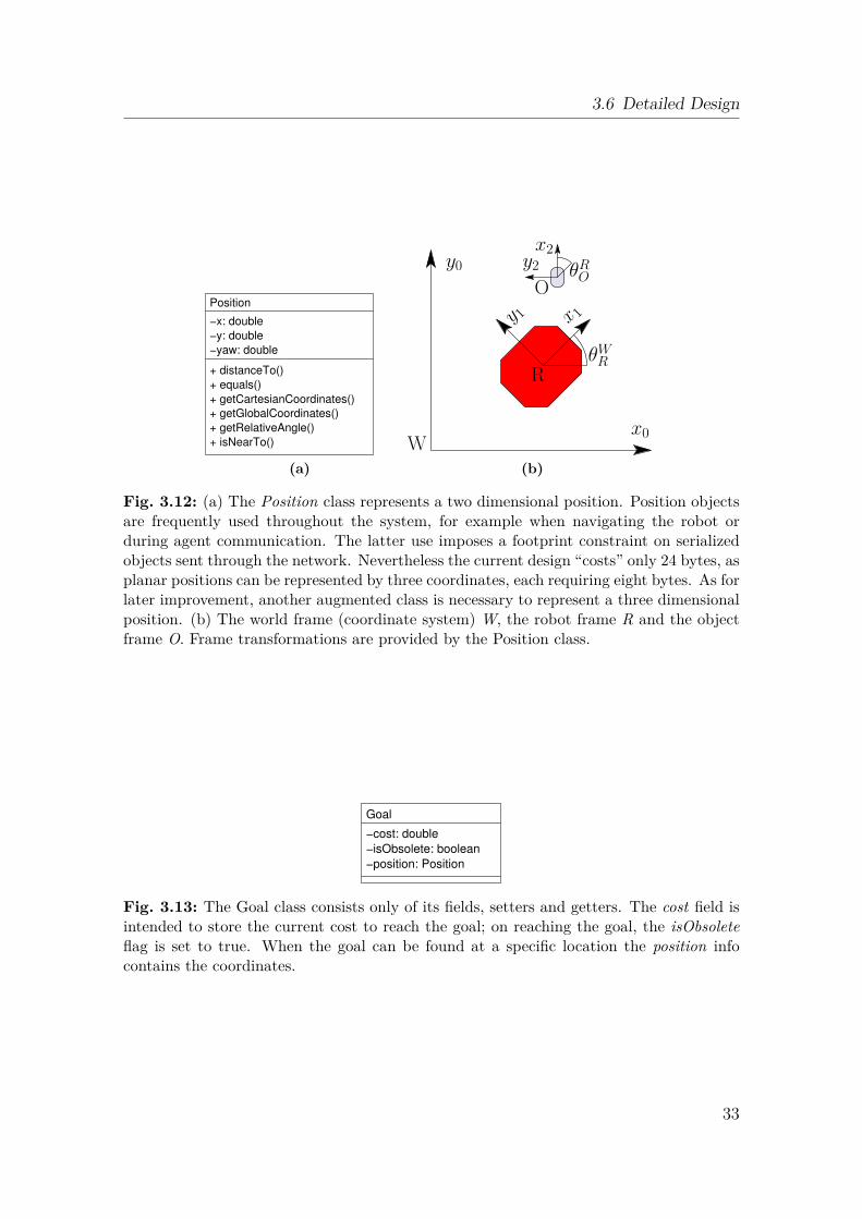
The data component contains central data types used throughout other components.The fundamental type is Position which is depicted in figure 3.12a. The distanceTomethod calculates the Euclidean distance (
√|x− x′|2 + |y − y′|2) between two posi-
tions. equals returns true if two positions match exactly, false otherwise. isNearToreturns true if one position is near to another, considering the given acceptabledeviation. An acceptable delta is given in meters for the planar distance and inradians for the angle. getCartesianCoordinates considers the actual coordinates inpolar form (x takes the range and yaw the angle θ) and returns its transformed(x = r · cos(θ), y = r · sin(θ), yaw = 0) cartesian coordinates.
30
3.6 Detailed Design
Hunt and Prey Scenario (XML)
Agent
Follow FollowAgent
Agent
Escape
follow
follow
� �[ . . . ]
<arguments>[ . . . ]
4 </ arguments>
<componenttypes><componenttype name=" Escape0 " [ . . . ]<componenttype name=" Follow0 " [ . . . ]
9 </componenttypes>
<a p p l i c a t i o n s><a p p l i c a t i o n name="1 Robot , Tams floor , real ">
<components>14 <component t ype=" Escape0 " name=" Escape0 ">
<arguments>[ . . . ]
</ arguments></component>
19 </ components></ a p p l i c a t i o n>
<a p p l i c a t i o n name="3 Robots , Tams floor , real "><components>
24 <component t ype=" Escape0 " name=" Escape0 ">[ . . . ]
<component t ype=" Follow0 " name=" Follow0 ">[ . . . ]
</ components>29 </ a p p l i c a t i o n>
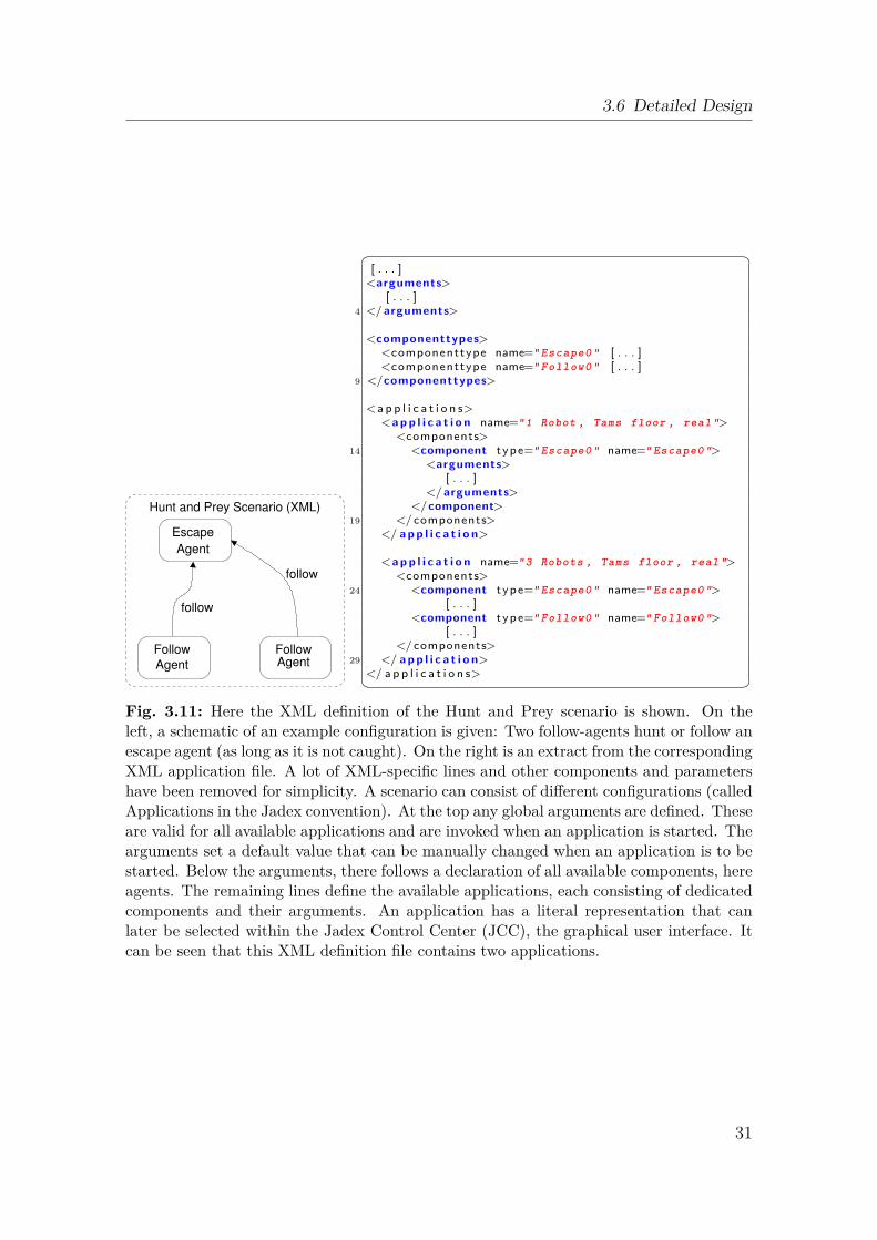
</ a p p l i c a t i o n s>� �Fig. 3.11: Here the XML definition of the Hunt and Prey scenario is shown. On theleft, a schematic of an example configuration is given: Two follow-agents hunt or follow anescape agent (as long as it is not caught). On the right is an extract from the correspondingXML application file. A lot of XML-specific lines and other components and parametershave been removed for simplicity. A scenario can consist of different configurations (calledApplications in the Jadex convention). At the top any global arguments are defined. Theseare valid for all available applications and are invoked when an application is started. Thearguments set a default value that can be manually changed when an application is to bestarted. Below the arguments, there follows a declaration of all available components, hereagents. The remaining lines define the available applications, each consisting of dedicatedcomponents and their arguments. An application has a literal representation that canlater be selected within the Jadex Control Center (JCC), the graphical user interface. Itcan be seen that this XML definition file contains two applications.
31
3 Approach
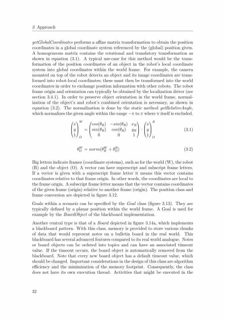
getGlobalCoordinates performs a affine matrix transformation to obtain the positioncoordinates in a global coordinate system referenced by the (global) position given.A homogeneous matrix contains the rotational and translatory transformation asshown in equation (3.1). A typical use-case for this method would be the trans-formation of the position coordinates of an object in the robot’s local coordinatesystem into global coordinates within the world frame. For example, the cameramounted on top of the robot detects an object and its image coordinates are trans-formed into robot-local coordinates; these must then be transformed into the worldcoordinates in order to exchange position information with other robots. The robotframe origin and orientation can typically be obtained by the localization driver (seesection 3.4.1). In order to preserve object orientation in the world frame, normal-ization of the object’s and robot’s combined orientation is necessary, as shown inequation (3.2). The normalization is done by the static method getRelativeAngle,which normalizes the given angle within the range −π to π where π itself is excluded.
xy1
W
O
=
cos(θR) −sin(θR) xR
sin(θR) cos(θR) yR
0 0 1
·xy
1
R
O
(3.1)
θWO = norm(θW
R + θRO) (3.2)
Big letters indicate frames (coordinate systems), such as for the world (W), the robot(R) and the object (O). A vector can have superscript and subscript frame letters.If a vector is given with a superscript frame letter it means this vector containscoordinates relative to that frame origin. In other words, the coordinates are local tothe frame origin. A subscript frame letter means that the vector contains coordinatesof the given frame (origin) relative to another frame (origin). The position class andframe conversion are depicted in figure 3.12.
Goals within a scenario can be specified by the Goal class (figure 3.13). They aretypically defined by a planar position within the world frame. A Goal is used forexample by the BoardObject of the blackboard implementation.
Another central type is that of a Board depicted in figure 3.14a, which implementsa blackboard pattern. With this class, memory is provided to store various chunksof data that would represent notes on a bulletin board in the real world. Thisblackboard has several advanced features compared to its real world analogue. Notesor board objects can be ordered into topics and can have an associated timeoutvalue. If the timeout occurs, the board object is automatically removed from theblackboard. Note that every new board object has a default timeout value, whichshould be changed. Important considerations in the design of this class are algorithmefficiency and the minimization of the memory footprint. Consequently, the classdoes not have its own execution thread. Activities that might be executed in the
32
3.6 Detailed Design
+ isNearTo()
−y: double
−yaw: double
+ getCartesianCoordinates()
+ getGlobalCoordinates()
+ getRelativeAngle()
−x: double
+ distanceTo()
+ equals()
Position
(a)
y0
x0
θROy2x2
Oy 1 x 1
W
RθWR
(b)
Fig. 3.12: (a) The Position class represents a two dimensional position. Position objectsare frequently used throughout the system, for example when navigating the robot orduring agent communication. The latter use imposes a footprint constraint on serializedobjects sent through the network. Nevertheless the current design “costs” only 24 bytes, asplanar positions can be represented by three coordinates, each requiring eight bytes. As forlater improvement, another augmented class is necessary to represent a three dimensionalposition. (b) The world frame (coordinate system) W, the robot frame R and the objectframe O. Frame transformations are provided by the Position class.
−isObsolete: boolean
Goal
−position: Position
−cost: double
Fig. 3.13: The Goal class consists only of its fields, setters and getters. The cost field isintended to store the current cost to reach the goal; on reaching the goal, the isObsoleteflag is set to true. When the goal can be found at a specific location the position infocontains the coordinates.
33

3 Approach
+ getTopicList()
+ removeObject()
+ setTimeout()
+ getArrayList()
−objectHm: ConcurrentHashMap
+ getObject()
−timeout: long
+ addObject()
Board
+ clear()
(a)
−timestamp: long
−position: Position
BoardObject
+ getDistanceGoal()
−distanceGoal: double
−isDone: boolean
−timeout: long
−topic: String
−goal: Goal
+ setDone()
+ setTimeout()
+ setPosition()
+ setGoal()
+ setTopic()
in milliseconds
Note:
+ isDone()
+ setDistanceGoal()
+ getTopic()
+ getTimestamp()
+ getPosition()
+ getGoal()
(b)
Fig. 3.14: Flexible information storage is achieved using the blackboard design pattern.(a) A Board object can store and manage many BoardObjects within an associative mem-ory type. Objects can be accessed by a topic-sensitive filter. An advanced feature is agarbage cleaner that efficiently clears expired (too old) board objects. (b) A board objectshould be flexible in terms of the information it can contain. The fields are optional andshould be used according to the information being stored by the caller. Unless the callerspecifies its lifespan, a default timeout is set when creating a new object.
background by a class thread, such as removing expired board objects, must beperformed when board methods are externally called, slightly increasing methodlatency. Information is provided within a BoardObject.
The type BlobfinderBlob (figure 3.15) is used to store information about coloredareas of an image retrieved by the Blobfinder device.
3.6.2.2 Robot
The Robot component contains a generic Robot class from which currently imple-mented specialized robots inherit, as depicted in figure 3.16. The Robot base classrepresents a mobile robot moving on the ground. The specialized Pioneer robotadds a behavioral model and states that can be monitored. It can be controlledeither with the setCommand method to give it manual motor commands, or usingthe setWallfollow method to activate autonomous wall-following. Both behaviorsapply obstacle avoidance (figure 3.23).
34
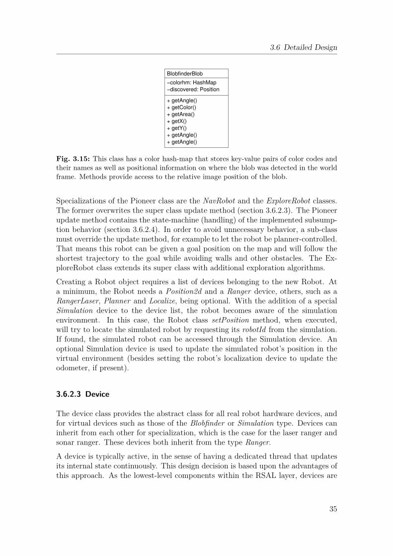
3.6 Detailed Design
−discovered: Position
BlobfinderBlob
+ getX()
+ getY()
+ getAngle()
+ getAngle()
−colorhm: HashMap
+ getAngle()
+ getColor()
+ getArea()
Fig. 3.15: This class has a color hash-map that stores key-value pairs of color codes andtheir names as well as positional information on where the blob was detected in the worldframe. Methods provide access to the relative image position of the blob.
Specializations of the Pioneer class are the NavRobot and the ExploreRobot classes.The former overwrites the super class update method (section 3.6.2.3). The Pioneerupdate method contains the state-machine (handling) of the implemented subsump-tion behavior (section 3.6.2.4). In order to avoid unnecessary behavior, a sub-classmust override the update method, for example to let the robot be planner-controlled.That means this robot can be given a goal position on the map and will follow theshortest trajectory to the goal while avoiding walls and other obstacles. The Ex-ploreRobot class extends its super class with additional exploration algorithms.
Creating a Robot object requires a list of devices belonging to the new Robot. Ata minimum, the Robot needs a Position2d and a Ranger device, others, such as aRangerLaser, Planner and Localize, being optional. With the addition of a specialSimulation device to the device list, the robot becomes aware of the simulationenvironment. In this case, the Robot class setPosition method, when executed,will try to locate the simulated robot by requesting its robotId from the simulation.If found, the simulated robot can be accessed through the Simulation device. Anoptional Simulation device is used to update the simulated robot’s position in thevirtual environment (besides setting the robot’s localization device to update theodometer, if present).
3.6.2.3 Device
The device class provides the abstract class for all real robot hardware devices, andfor virtual devices such as those of the Blobfinder or Simulation type. Devices caninherit from each other for specialization, which is the case for the laser ranger andsonar ranger. These devices both inherit from the type Ranger.
A device is typically active, in the sense of having a dedicated thread that updatesits internal state continuously. This design decision is based upon the advantages ofthis approach. As the lowest-level components within the RSAL layer, devices are
35
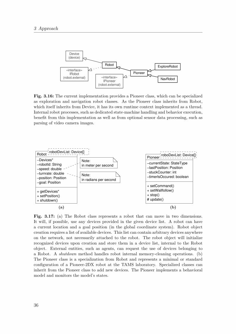
3 Approach
Device(device)
ExploreRobot
NavRobot
Pioneer
Robot
«interface»IPioneer
(robot.external)
«interface»IRobot
(robot.external)
Fig. 3.16: The current implementation provides a Pioneer class, which can be specializedas exploration and navigation robot classes. As the Pioneer class inherits from Robot,which itself inherits from Device, it has its own runtime context implemented as a thread.Internal robot processes, such as dedicated state-machine handling and behavior execution,benefit from this implementation as well as from optional sensor data processing, such asparsing of video camera images.
−position: Position
−robotId: String
−turnrate: double
−goal: Position
Robot
+ shutdown()
Note:
in radians per second
−speed: double
robotDevList: Device[]
−Devices*
in meter per second
Note:
+ setPosition()
+ getDevices*
(a)
−timerIsOccured: boolean
−currentState: StateType
−lastPosition: Position
−stuckCounter: int
+ setCommand()
+ setWallfollow()
+ stop()
# update()
PioneerroboDevList: Device[]
(b)
Fig. 3.17: (a) The Robot class represents a robot that can move in two dimensions.It will, if possible, use any devices provided in the given device list. A robot can havea current location and a goal position (in the global coordinate system). Robot objectcreation requires a list of available devices. This list can contain arbitrary devices anywhereon the network, not necessarily attached to the robot. The robot object will initializerecognized devices upon creation and store them in a device list, internal to the Robotobject. External entities, such as agents, can request the use of devices belonging toa Robot. A shutdown method handles robot internal memory-cleaning operations. (b)The Pioneer class is a specialization from Robot and represents a minimal or standardconfiguration of a Pioneer-2DX robot at the TAMS laboratory. Specialized classes caninherit from the Pioneer class to add new devices. The Pioneer implements a behavioralmodel and monitors the model’s states.
36
3.6 Detailed Design
normally heavily dependent on sensory input, such as range values or localizationhypotheses from the underlying drivers and hardware. This imposes strong real-timeconstraints on the design (and hardware dependencies).In the high-level interface provided to a Robot class (or to even more abstract“users”, such as agents) the requirements are high availability, concurrency andasynchronism. These can be achieved by using the thread to poll the hardware andfill internal data structures. Requests for device data can then be provided with thelatest readings without the delays associated with access to the hardware. This isindicated in figure 3.19. Certain operations can take a long time, such as arriving ata goal position. Therefore the callback pattern provides the caller with informationonly if relevant data is ready, which lets the caller conserve its resources for as longas possible.As some devices have other devices attached (logically or physically), objects can belinked within an ordered hierarchy of devices. For example a robot is representedas a device and typically has other devices, such as ranger sensors, mounted. Thisintroduces recursion into the class model. To cope with this requirement, an objectof the Device class has an internal data structure listing other devices.In order to be able to search for or compare devices at runtime, several relatedmethods are provided. To check for identical devices the equals method is available.A similar method matches also compares the given devices but can accept a devicethat does not have all information defined. Such a partially defined device can beviewed as a device template or search mask. The list counterparts of these twomethods, implemented as isInList and matchesList, search the internal device listwith the information provided.The abstract method update must be implemented by sub-classes. It contains theperiodic task that a device must maintain to remain in sync with its underlyinghardware. This method is called periodically within the Device (thread) context.Typical update method tasks are reading the most recent values and updating in-ternal data structures and states. For a gripper device, the periodic task would beto read the current optical sensor states via the Dio device (page 41), to update theinternal state machine and, if requested, to set a new state. The periodic task isprocessed in the run-loop of the device.After each update cycle, the Device class suspends the device (thread) for the timeset in the class sleeptime field. Upon resuming, the update is repeated. The durationof the update processing is typically very much smaller than the sleeptime. Unlessthe device is shut down, this cycle will repeat forever. There is a trade-off between ahighly responsive device (which has less sleeptime) and a resource efficient one (whichhas a higher sleeptime). Whereas some devices, such as grippers or localizationdevices, take rather long times to update their internal states, often more than halfa second, there are devices that require small sleep times: for example, less than atenth of a second, for a laser ranger device. Typical robot devices work well with a
37
3 Approach
sleep time of 100 milliseconds. This is a good trade-off between responsiveness andresource saving and is the default value if not changed.
A Device object has to be explicitly started by the runThreaded method. Thisinvokes internal threading and takes care of the startup of internal devices. Tostop a device, the shutdown method must be invoked, which also handles sub-deviceshutdown. Both startup and shutdown, where there is a list of internal devices, canbe seen as a recursive cascade that calls all devices in the list. If a new device hasan embedded, dynamic, data structure, it should overwrite the shutdown method.
A special Device class is the DeviceNode. Its purpose is to encapsulate all deviceaccess from the underlying MRS. Different MRS might have similar but neverthelessslightly different methods to access their devices. A DeviceNode must be createdwith a list of hosts and devices, where a host is identified with its name or addressand the port on which a client listens. The device list contains templates of anycombination of id, host, port and index, some of which may be omitted to providea device mask matching multiple combinations. Here the id field identifies the typeof device; host and port fields are as described in section 3.5. It is possible tohave multiple devices of the same type (id) on the same host/port combination.In this case the index can be used to define the exact device. Upon creation ofthe DeviceNode object, the given hosts will be searched for devices matching anytemplates. When a matching device is found it is added to an internal device list;when the device is bound to a new PlayerClient (a Player/Stage specific device node,see section 4.5), the PlayerClient is added to a DeviceNode internal list (which is adedicated field of the DeviceNode class). Note that the PlayerClient class is providedby Player/Stage and, as it introduces a dependency on the MRS, must always beencapsulated within a DeviceNode.
After initialization, a DeviceNode has a flat list of all sub-devices and DeviceNodes(this is the list/field inherited from the Device class, figure 3.18a). During runtime,DeviceNode provides a dynamic interface for managed devices and moreover allowsmasked searches for specific devices.
The Localize Device class implements features that locate the robot within a worldframe. It uses the underlying MRS localization driver, currently AMCL, encapsu-lates any dependencies and provides a consistent interface. Furthermore it decouplesperformance constraints from the driver by providing an asynchronous interface. Theuser of the class can rely upon the immediate return of the latest position data. Theinterface provides a callback notification feature. Any listeners interested in periodicposition updates can subscribe with the addListener method. Clients interested incurrent location information use the getPosition method. In the run-loop methodupdate, the localization device is periodically updated. To allow the position beliefto be explicitly set, the method setPosition is provided. As most localization algo-rithms keep track of the current position hypotheses with a covariance matrix, thematrix is contained as a field. This field sets the probability distribution at the start.
38
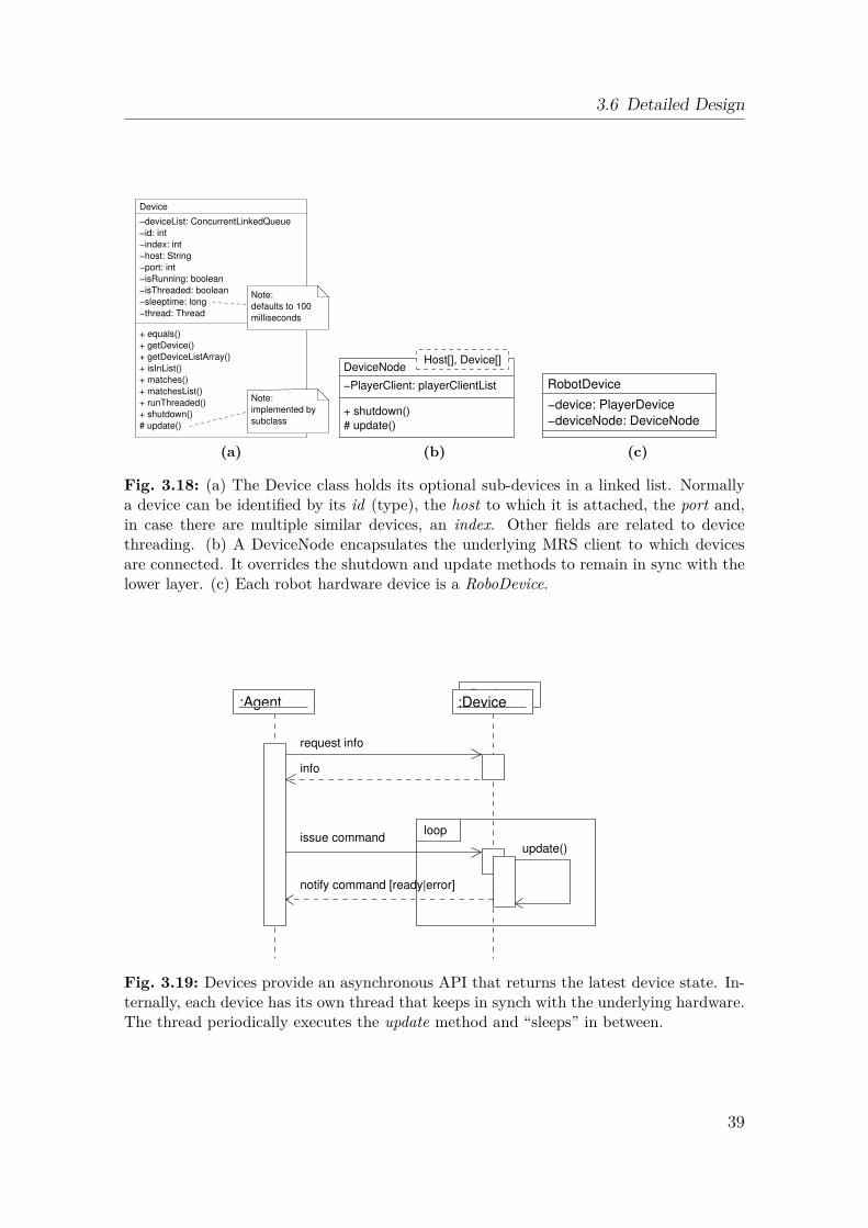
3.6 Detailed Design
−id: int
−index: int
−host: String
−port: int
−isThreaded: boolean
−isRunning: boolean
−sleeptime: long
−thread: Thread
Device
+ isInList()
+ runThreaded()
+ shutdown()
# update()
−deviceList: ConcurrentLinkedQueue
+ getDevice()
+ getDeviceListArray()
+ matches()
+ matchesList()
+ equals()
subclass
implemented by
Note:
milliseconds
defaults to 100
Note:
(a)
DeviceNodeHost[], Device[]
+ shutdown()
# update()
−PlayerClient: playerClientList
(b)
−deviceNode: DeviceNode
RobotDevice
−device: PlayerDevice
(c)
Fig. 3.18: (a) The Device class holds its optional sub-devices in a linked list. Normallya device can be identified by its id (type), the host to which it is attached, the port and,in case there are multiple similar devices, an index. Other fields are related to devicethreading. (b) A DeviceNode encapsulates the underlying MRS client to which devicesare connected. It overrides the shutdown and update methods to remain in sync with thelower layer. (c) Each robot hardware device is a RoboDevice.
:Agent:Device
loopissue command
info
notify command [ready|error]
:Device
request info
update()
Fig. 3.19: Devices provide an asynchronous API that returns the latest device state. In-ternally, each device has its own thread that keeps in synch with the underlying hardware.The thread periodically executes the update method and “sleeps” in between.
39
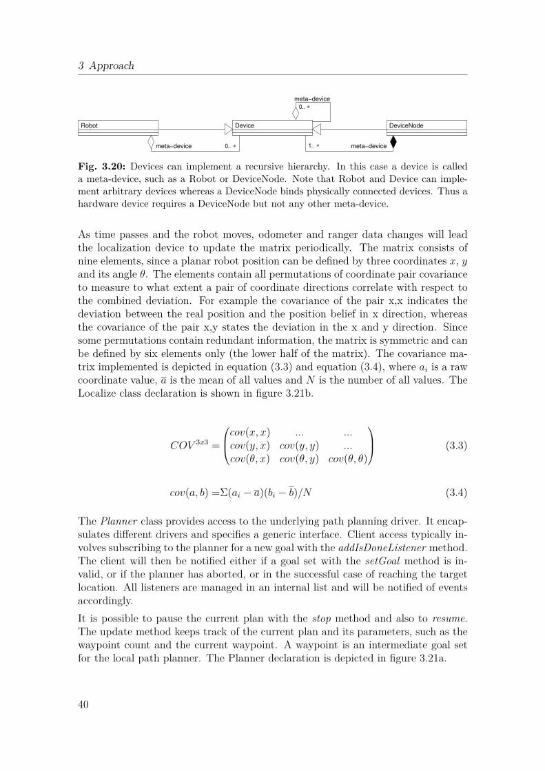
3 Approach
DeviceNode
0.. ∗ 1.. ∗
Device
meta−device
meta−device
Robot
0..
meta−device
∗
Fig. 3.20: Devices can implement a recursive hierarchy. In this case a device is calleda meta-device, such as a Robot or DeviceNode. Note that Robot and Device can imple-ment arbitrary devices whereas a DeviceNode binds physically connected devices. Thus ahardware device requires a DeviceNode but not any other meta-device.
As time passes and the robot moves, odometer and ranger data changes will leadthe localization device to update the matrix periodically. The matrix consists ofnine elements, since a planar robot position can be defined by three coordinates x, yand its angle θ. The elements contain all permutations of coordinate pair covarianceto measure to what extent a pair of coordinate directions correlate with respect tothe combined deviation. For example the covariance of the pair x,x indicates thedeviation between the real position and the position belief in x direction, whereasthe covariance of the pair x,y states the deviation in the x and y direction. Sincesome permutations contain redundant information, the matrix is symmetric and canbe defined by six elements only (the lower half of the matrix). The covariance ma-trix implemented is depicted in equation (3.3) and equation (3.4), where ai is a rawcoordinate value, a is the mean of all values and N is the number of all values. TheLocalize class declaration is shown in figure 3.21b.
COV 3x3 =
cov(x, x) ... ...cov(y, x) cov(y, y) ...cov(θ, x) cov(θ, y) cov(θ, θ)
(3.3)
cov(a, b) =Σ(ai − a)(bi − b)/N (3.4)
The Planner class provides access to the underlying path planning driver. It encap-sulates different drivers and specifies a generic interface. Client access typically in-volves subscribing to the planner for a new goal with the addIsDoneListener method.The client will then be notified either if a goal set with the setGoal method is in-valid, or if the planner has aborted, or in the successful case of reaching the targetlocation. All listeners are managed in an internal list and will be notified of eventsaccordingly.It is possible to pause the current plan with the stop method and also to resume.The update method keeps track of the current plan and its parameters, such as thewaypoint count and the current waypoint. A waypoint is an intermediate goal setfor the local path planner. The Planner declaration is depicted in figure 3.21a.
40
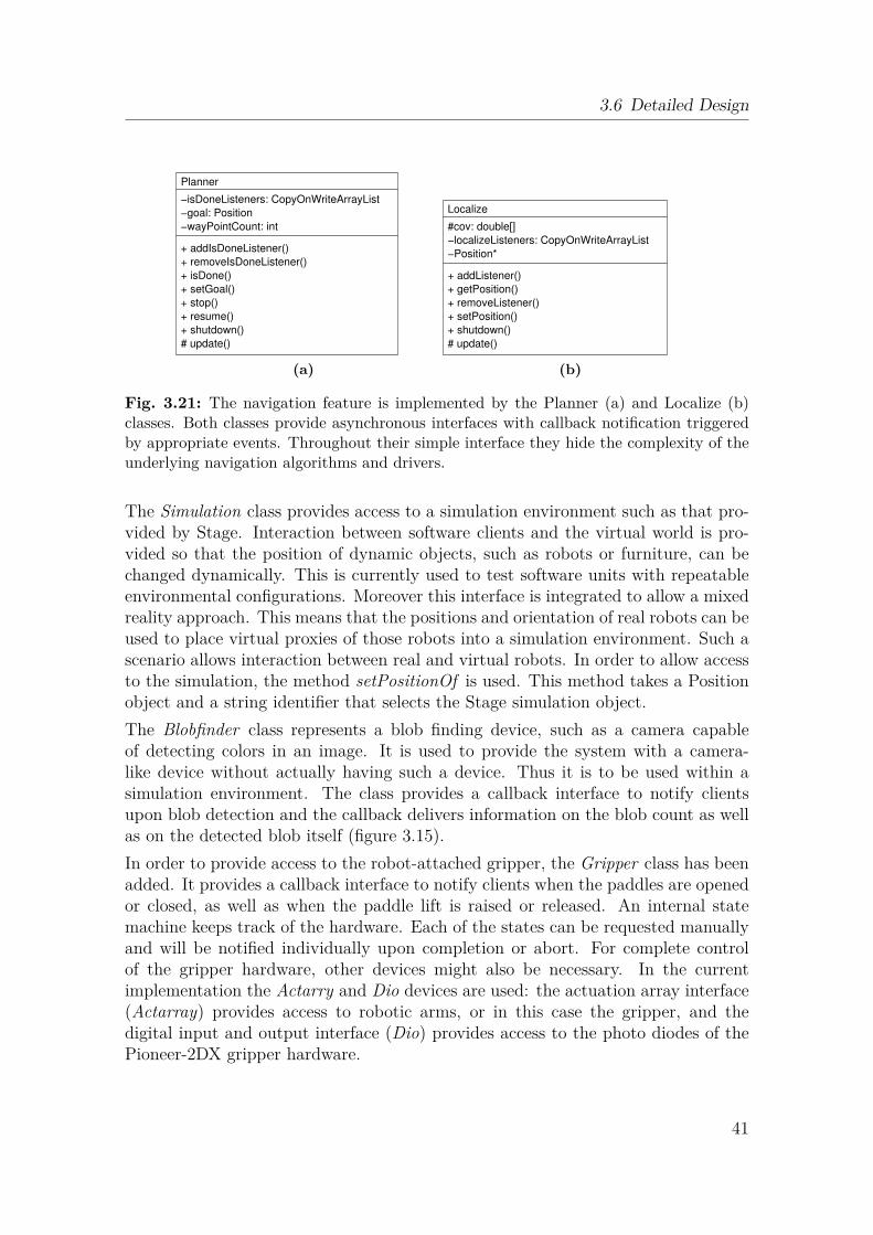
3.6 Detailed Design
Planner
+ addIsDoneListener()
+ setGoal()
+ resume()
+ shutdown()
# update()
+ stop()
+ removeIsDoneListener()
+ isDone()
−isDoneListeners: CopyOnWriteArrayList
−goal: Position
−wayPointCount: int
(a)
Localize
+ shutdown()
+ removeListener()
#cov: double[]
+ getPosition()
+ setPosition()
# update()
−localizeListeners: CopyOnWriteArrayList
−Position*
+ addListener()
(b)
Fig. 3.21: The navigation feature is implemented by the Planner (a) and Localize (b)classes. Both classes provide asynchronous interfaces with callback notification triggeredby appropriate events. Throughout their simple interface they hide the complexity of theunderlying navigation algorithms and drivers.
The Simulation class provides access to a simulation environment such as that pro-vided by Stage. Interaction between software clients and the virtual world is pro-vided so that the position of dynamic objects, such as robots or furniture, can bechanged dynamically. This is currently used to test software units with repeatableenvironmental configurations. Moreover this interface is integrated to allow a mixedreality approach. This means that the positions and orientation of real robots can beused to place virtual proxies of those robots into a simulation environment. Such ascenario allows interaction between real and virtual robots. In order to allow accessto the simulation, the method setPositionOf is used. This method takes a Positionobject and a string identifier that selects the Stage simulation object.The Blobfinder class represents a blob finding device, such as a camera capableof detecting colors in an image. It is used to provide the system with a camera-like device without actually having such a device. Thus it is to be used within asimulation environment. The class provides a callback interface to notify clientsupon blob detection and the callback delivers information on the blob count as wellas on the detected blob itself (figure 3.15).In order to provide access to the robot-attached gripper, the Gripper class has beenadded. It provides a callback interface to notify clients when the paddles are openedor closed, as well as when the paddle lift is raised or released. An internal statemachine keeps track of the hardware. Each of the states can be requested manuallyand will be notified individually upon completion or abort. For complete controlof the gripper hardware, other devices might also be necessary. In the currentimplementation the Actarry and Dio devices are used: the actuation array interface(Actarray) provides access to robotic arms, or in this case the gripper, and thedigital input and output interface (Dio) provides access to the photo diodes of thePioneer-2DX gripper hardware.
41
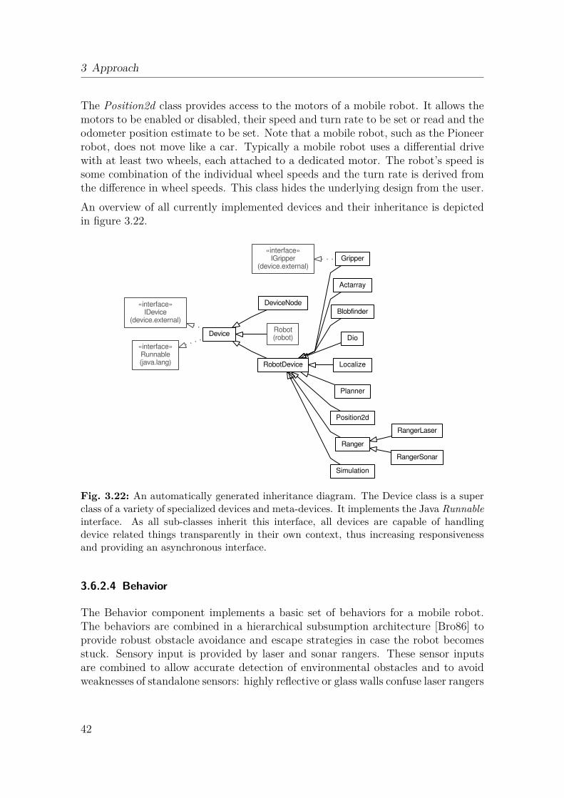
3 Approach
The Position2d class provides access to the motors of a mobile robot. It allows themotors to be enabled or disabled, their speed and turn rate to be set or read and theodometer position estimate to be set. Note that a mobile robot, such as the Pioneerrobot, does not move like a car. Typically a mobile robot uses a differential drivewith at least two wheels, each attached to a dedicated motor. The robot’s speed issome combination of the individual wheel speeds and the turn rate is derived fromthe difference in wheel speeds. This class hides the underlying design from the user.An overview of all currently implemented devices and their inheritance is depictedin figure 3.22.
Actarray
Blobfinder
Device
DeviceNode
Dio
Gripper
Localize
Planner
Position2d
Ranger
RangerLaser
RangerSonar
Robot(robot)
RobotDevice
Simulation
«interface»IDevice
(device.external)
«interface»IGripper
(device.external)
«interface»Runnable(java.lang)
Fig. 3.22: An automatically generated inheritance diagram. The Device class is a superclass of a variety of specialized devices and meta-devices. It implements the Java Runnableinterface. As all sub-classes inherit this interface, all devices are capable of handlingdevice related things transparently in their own context, thus increasing responsivenessand providing an asynchronous interface.
3.6.2.4 Behavior
The Behavior component implements a basic set of behaviors for a mobile robot.The behaviors are combined in a hierarchical subsumption architecture [Bro86] toprovide robust obstacle avoidance and escape strategies in case the robot becomesstuck. Sensory input is provided by laser and sonar rangers. These sensor inputsare combined to allow accurate detection of environmental obstacles and to avoidweaknesses of standalone sensors: highly reflective or glass walls confuse laser rangers
42
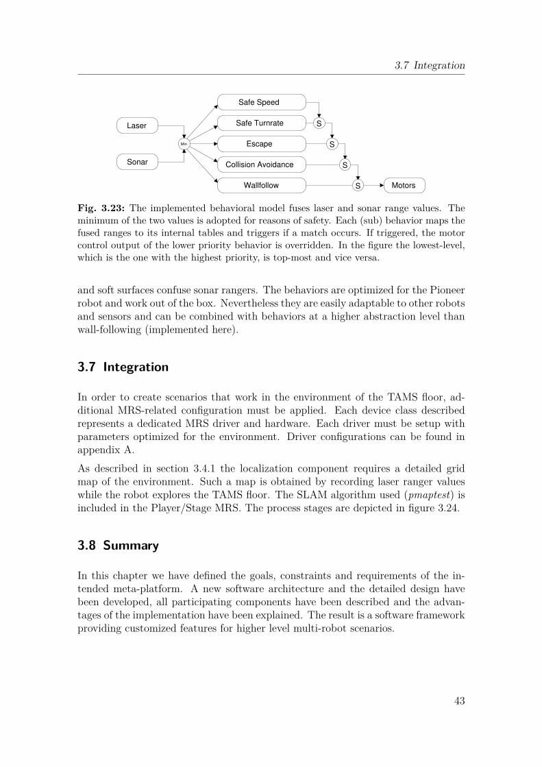
3.7 Integration
Min
Wallfollow Motors
Safe Turnrate
Safe Speed
Escape
Collision Avoidance
Laser
S
S
S
SSonar
Fig. 3.23: The implemented behavioral model fuses laser and sonar range values. Theminimum of the two values is adopted for reasons of safety. Each (sub) behavior maps thefused ranges to its internal tables and triggers if a match occurs. If triggered, the motorcontrol output of the lower priority behavior is overridden. In the figure the lowest-level,which is the one with the highest priority, is top-most and vice versa.
and soft surfaces confuse sonar rangers. The behaviors are optimized for the Pioneerrobot and work out of the box. Nevertheless they are easily adaptable to other robotsand sensors and can be combined with behaviors at a higher abstraction level thanwall-following (implemented here).
3.7 Integration
In order to create scenarios that work in the environment of the TAMS floor, ad-ditional MRS-related configuration must be applied. Each device class describedrepresents a dedicated MRS driver and hardware. Each driver must be setup withparameters optimized for the environment. Driver configurations can be found inappendix A.As described in section 3.4.1 the localization component requires a detailed gridmap of the environment. Such a map is obtained by recording laser ranger valueswhile the robot explores the TAMS floor. The SLAM algorithm used (pmaptest) isincluded in the Player/Stage MRS. The process stages are depicted in figure 3.24.
3.8 Summary
In this chapter we have defined the goals, constraints and requirements of the in-tended meta-platform. A new software architecture and the detailed design havebeen developed, all participating components have been described and the advan-tages of the implementation have been explained. The result is a software frameworkproviding customized features for higher level multi-robot scenarios.
43
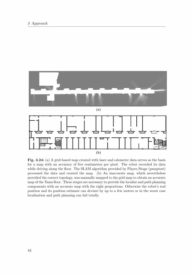
3 Approach
(a)
(b)
Fig. 3.24: (a) A grid-based map created with laser and odometer data serves as the basisfor a map with an accuracy of five centimeters per pixel. The robot recorded its datawhile driving along the floor. The SLAM algorithm provided by Player/Stage (pmaptest)processed the data and created the map. (b) An inaccurate map, which neverthelessprovided the correct topology, was manually mapped to the grid map to obtain an accuratemap of the Tams floor. These stages are necessary to provide the localize and path planningcomponents with an accurate map with the right proportions. Otherwise the robot’s realposition and its position estimate can deviate by up to a few meters or in the worst caselocalization and path planning can fail totally.
44
Scenarios
4In chapter 3 we developed a middle layer to abstract from an MRS and to integratean MAS. The MAS provides high-level cognitive features that allow the planning ofcomplex scenarios in which multiple robots cooperate in order to reach a commongoal. A scenario plan depends strongly upon the specific use-case but should ideallybe suitable for re-use. In this work, sample scenarios were created to demonstratethe working concept of an integrated middle layer. These scenarios can be reusedin other scenarios.
4.1 Introduction
This chapter describes how the presented middle layer can be used within a meta-platform that also integrates MAS and MRS. A choice of scenarios serves as aframework to describe all necessary software modules, techniques and configurations.In the following section, each scenario is discussed briefly and possible improvementsare suggested. Subsequently, migration to another MAS and MRS is introducedbefore a summary closes the chapter.
4.2 Example Scenarios
This section introduces scenarios that demonstrate the basic features of the meta-platform. The ideas for the Hunt and Prey and Find and Collect scenarios are takenfrom the MAS Jadex code examples (comes with Jadex) whereas the 100 Robots andSwarm Distribution scenarios are new. Together, these scenarios demonstrate thebasic functionality of the platform and provide a code template for other tasks.In the Hunt and Prey (an extended Hide and Seek) scenario, two or more robotslook for and try to catch a hiding robot. The hunting robots coordinate their searchto increase efficiency.In the Cleaner World scenario, two or more robots collect trash or specially markedobjects, coordinating their search to cover the work area efficiently. As an extension,a constraint could be to conserve robot battery life. An example implementation is
45
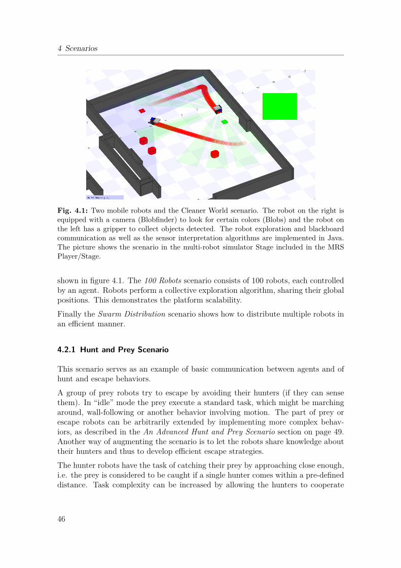
4 Scenarios
Fig. 4.1: Two mobile robots and the Cleaner World scenario. The robot on the right isequipped with a camera (Blobfinder) to look for certain colors (Blobs) and the robot onthe left has a gripper to collect objects detected. The robot exploration and blackboardcommunication as well as the sensor interpretation algorithms are implemented in Java.The picture shows the scenario in the multi-robot simulator Stage included in the MRSPlayer/Stage.
shown in figure 4.1. The 100 Robots scenario consists of 100 robots, each controlledby an agent. Robots perform a collective exploration algorithm, sharing their globalpositions. This demonstrates the platform scalability.Finally the Swarm Distribution scenario shows how to distribute multiple robots inan efficient manner.
4.2.1 Hunt and Prey Scenario
This scenario serves as an example of basic communication between agents and ofhunt and escape behaviors.A group of prey robots try to escape by avoiding their hunters (if they can sensethem). In “idle” mode the prey execute a standard task, which might be marchingaround, wall-following or another behavior involving motion. The part of prey orescape robots can be arbitrarily extended by implementing more complex behav-iors, as described in the An Advanced Hunt and Prey Scenario section on page 49.Another way of augmenting the scenario is to let the robots share knowledge abouttheir hunters and thus to develop efficient escape strategies.The hunter robots have the task of catching their prey by approaching close enough,i.e. the prey is considered to be caught if a single hunter comes within a pre-defineddistance. Task complexity can be increased by allowing the hunters to cooperate
46
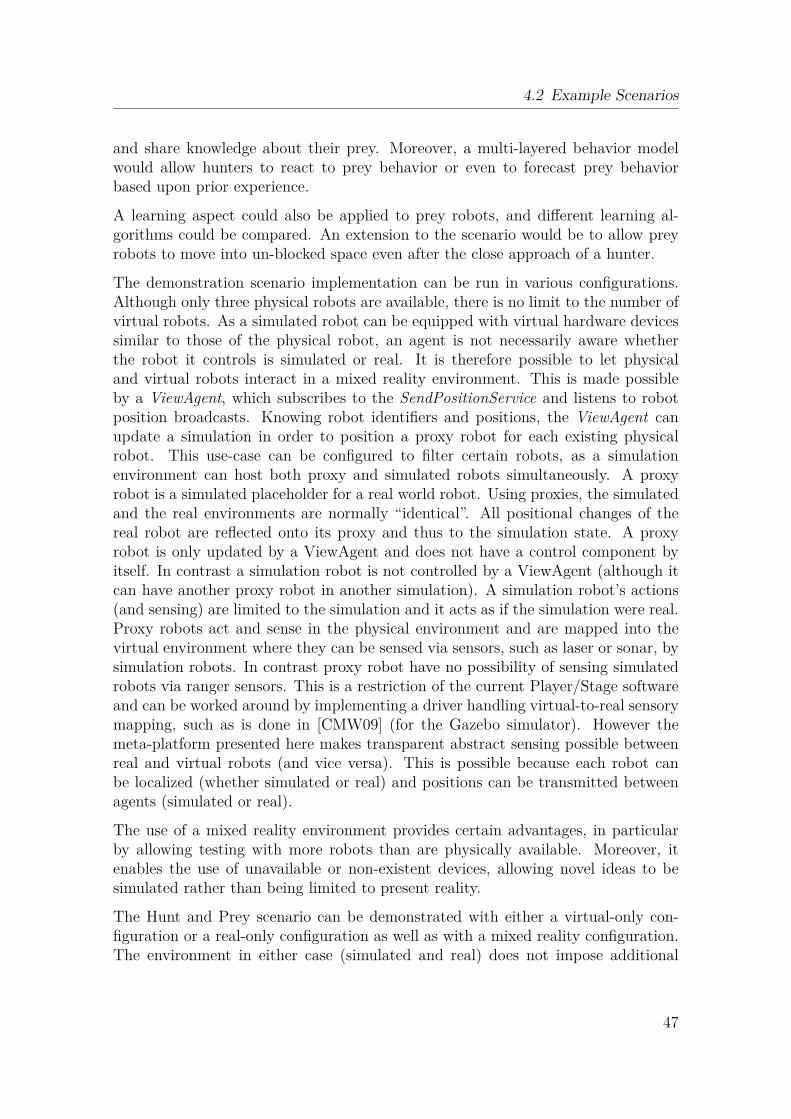
4.2 Example Scenarios
and share knowledge about their prey. Moreover, a multi-layered behavior modelwould allow hunters to react to prey behavior or even to forecast prey behaviorbased upon prior experience.
A learning aspect could also be applied to prey robots, and different learning al-gorithms could be compared. An extension to the scenario would be to allow preyrobots to move into un-blocked space even after the close approach of a hunter.
The demonstration scenario implementation can be run in various configurations.Although only three physical robots are available, there is no limit to the number ofvirtual robots. As a simulated robot can be equipped with virtual hardware devicessimilar to those of the physical robot, an agent is not necessarily aware whetherthe robot it controls is simulated or real. It is therefore possible to let physicaland virtual robots interact in a mixed reality environment. This is made possibleby a ViewAgent, which subscribes to the SendPositionService and listens to robotposition broadcasts. Knowing robot identifiers and positions, the ViewAgent canupdate a simulation in order to position a proxy robot for each existing physicalrobot. This use-case can be configured to filter certain robots, as a simulationenvironment can host both proxy and simulated robots simultaneously. A proxyrobot is a simulated placeholder for a real world robot. Using proxies, the simulatedand the real environments are normally “identical”. All positional changes of thereal robot are reflected onto its proxy and thus to the simulation state. A proxyrobot is only updated by a ViewAgent and does not have a control component byitself. In contrast a simulation robot is not controlled by a ViewAgent (although itcan have another proxy robot in another simulation). A simulation robot’s actions(and sensing) are limited to the simulation and it acts as if the simulation were real.Proxy robots act and sense in the physical environment and are mapped into thevirtual environment where they can be sensed via sensors, such as laser or sonar, bysimulation robots. In contrast proxy robot have no possibility of sensing simulatedrobots via ranger sensors. This is a restriction of the current Player/Stage softwareand can be worked around by implementing a driver handling virtual-to-real sensorymapping, such as is done in [CMW09] (for the Gazebo simulator). However themeta-platform presented here makes transparent abstract sensing possible betweenreal and virtual robots (and vice versa). This is possible because each robot canbe localized (whether simulated or real) and positions can be transmitted betweenagents (simulated or real).
The use of a mixed reality environment provides certain advantages, in particularby allowing testing with more robots than are physically available. Moreover, itenables the use of unavailable or non-existent devices, allowing novel ideas to besimulated rather than being limited to present reality.
The Hunt and Prey scenario can be demonstrated with either a virtual-only con-figuration or a real-only configuration as well as with a mixed reality configuration.The environment in either case (simulated and real) does not impose additional
47
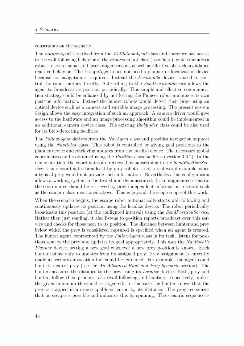
4 Scenarios
constraints on the scenario.The EscapeAgent is derived from the WallfollowAgent class and therefore has accessto the wall-following behavior of the Pioneer robot class (used here), which includes arobust fusion of sonar and laser ranger sensors, as well as effective obstacle-avoidancereactive behavior. The EscapeAgent does not need a planner or localization devicebecause no navigation is required. Instead the Position2d device is used to con-trol the robot motors directly. Subscribing to the SendPositionService allows theagent to broadcast its position periodically. This simple and effective communica-tion strategy could be enhanced by not letting the Pioneer robot announce its ownposition information. Instead the hunter robots would detect their prey using anoptical device such as a camera and suitable image processing. The present systemdesign allows the easy integration of such an approach. A camera driver would giveaccess to the hardware and an image processing algorithm could be implemented inan additional camera device class. The existing Blobfinder class could be also usedfor its blob-detecting facilities.The FollowAgent derives from the NavAgent class and provides navigation supportusing the NavRobot class. This robot is controlled by giving goal positions to theplanner device and retrieving updates from the localize device. The necessary globalcoordinates can be obtained using the Position class facilities (section 3.6.2). In thedemonstration, the coordinates are retrieved by subscribing to the SendPositionSer-vice. Using coordinates broadcast by prey robots is not a real world example, sincea typical prey would not provide such information. Nevertheless this configurationallows a working system to be tested and demonstrated. In an augmented scenariothe coordinates should be retrieved by prey-independent information retrieval suchas the camera class mentioned above. This is beyond the scope scope of this work.When the scenario begins, the escape robot automatically starts wall-following andcontinuously updates its position using the localize device. The robot periodicallybroadcasts this position (at the configured interval) using the SendPositionService.Rather than just sending, it also listens to position reports broadcast over this ser-vice and checks for those near to its position. The distance between hunter and preybelow which the prey is considered captured is specified when an agent is created.The hunter agent, represented by the FollowAgent class in its task, listens for posi-tions sent by the prey and updates its goal appropriately. This uses the NavRobot’sPlanner device, setting a new goal whenever a new prey position is known. Eachhunter listens only to updates from its assigned prey. Prey assignment is currentlymade at scenario invocation but could be extended. For example, the agent couldhunt its nearest prey (see the An Advanced Hunt and Prey Scenario section). Thehunter measures the distance to the prey using its Localize device. Both, prey andhunter, follow their primary task (wall-following and hunting, respectively) unlessthe given minimum threshold is triggered. In this case the hunter knows that theprey is trapped in an unescapable situation by its distance. The prey recognizesthat no escape is possible and indicates this by spinning. The scenario sequence is
48
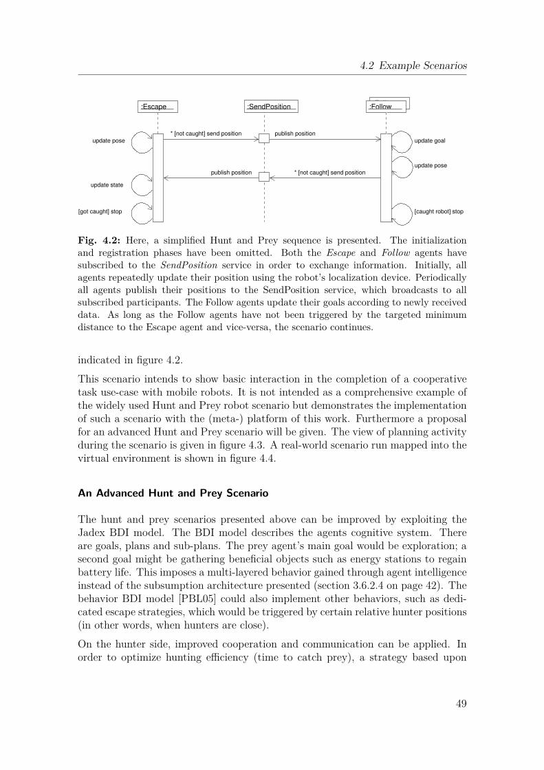
4.2 Example Scenarios
:Escape:Follow
:SendPosition
update pose
update state
[got caught] stop
* [not caught] send position
:Follow
publish position
[caught robot] stop
publish position
update pose
update goal
* [not caught] send position
Fig. 4.2: Here, a simplified Hunt and Prey sequence is presented. The initializationand registration phases have been omitted. Both the Escape and Follow agents havesubscribed to the SendPosition service in order to exchange information. Initially, allagents repeatedly update their position using the robot’s localization device. Periodicallyall agents publish their positions to the SendPosition service, which broadcasts to allsubscribed participants. The Follow agents update their goals according to newly receiveddata. As long as the Follow agents have not been triggered by the targeted minimumdistance to the Escape agent and vice-versa, the scenario continues.
indicated in figure 4.2.This scenario intends to show basic interaction in the completion of a cooperativetask use-case with mobile robots. It is not intended as a comprehensive example ofthe widely used Hunt and Prey robot scenario but demonstrates the implementationof such a scenario with the (meta-) platform of this work. Furthermore a proposalfor an advanced Hunt and Prey scenario will be given. The view of planning activityduring the scenario is given in figure 4.3. A real-world scenario run mapped into thevirtual environment is shown in figure 4.4.
An Advanced Hunt and Prey Scenario
The hunt and prey scenarios presented above can be improved by exploiting theJadex BDI model. The BDI model describes the agents cognitive system. Thereare goals, plans and sub-plans. The prey agent’s main goal would be exploration; asecond goal might be gathering beneficial objects such as energy stations to regainbattery life. This imposes a multi-layered behavior gained through agent intelligenceinstead of the subsumption architecture presented (section 3.6.2.4 on page 42). Thebehavior BDI model [PBL05] could also implement other behaviors, such as dedi-cated escape strategies, which would be triggered by certain relative hunter positions(in other words, when hunters are close).On the hunter side, improved cooperation and communication can be applied. Inorder to optimize hunting efficiency (time to catch prey), a strategy based upon
49
4 Scenarios
Fig. 4.3: Two robots (the blue and red circles) are collectively hunting one prey robot(yellow). Each robot follows its optimal path to the goal. The colored lines indicate theplanned trajectory. The small triangles on the trajectory mark temporary waypoints forthe local path planner. The global trajectory goal will be updated according to the preyrobot’s varying position. The robot’s current heading is indicated by the small trianglewithin the circle.
prey position relative to the hunter group formation can be applied. The hunterscan decide which team members chase which prey. This approach can increase thenumber of prey that can be hunted in parallel. It can also save resources by directinghunters to the nearest prey. This could be achieved by implementing the FIPA-Contract-Net protocol [Cer08], in which agents agree prey attribution dependingupon relative distances.
4.2.2 Find and Collect Scenario
The Find and Collect scenario was inspired by the Jadex Cleaner World exampleand the trash collecting robots in [MAC97]. The Cleaner World example can beconsidered a similar scenario. Two groups of robots participate: collecting robotsand exploration robots.The collecting robots fetch objects with their attached gripper and bring them backto their home position. A home position is defined for simplicity as the initial startposition of the robot and can be defined anywhere within the map upon agent cre-ation. An object can be any movable, physical item in the robot’s environment thatthe robot can move (for example, with its gripper). In the scenario implemented,an object is represented by a little square blob on the floor, a little smaller than thefootprint of the robot itself.The exploration robots explore unknown territory and can detect interesting ob-
50
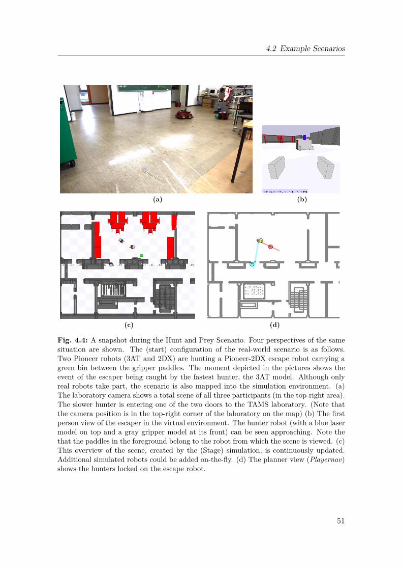
4.2 Example Scenarios
(a) (b)
(c) (d)
Fig. 4.4: A snapshot during the Hunt and Prey Scenario. Four perspectives of the samesituation are shown. The (start) configuration of the real-world scenario is as follows.Two Pioneer robots (3AT and 2DX) are hunting a Pioneer-2DX escape robot carrying agreen bin between the gripper paddles. The moment depicted in the pictures shows theevent of the escaper being caught by the fastest hunter, the 3AT model. Although onlyreal robots take part, the scenario is also mapped into the simulation environment. (a)The laboratory camera shows a total scene of all three participants (in the top-right area).The slower hunter is entering one of the two doors to the TAMS laboratory. (Note thatthe camera position is in the top-right corner of the laboratory on the map) (b) The firstperson view of the escaper in the virtual environment. The hunter robot (with a blue lasermodel on top and a gray gripper model at its front) can be seen approaching. Note thethat the paddles in the foreground belong to the robot from which the scene is viewed. (c)This overview of the scene, created by the (Stage) simulation, is continuously updated.Additional simulated robots could be added on-the-fly. (d) The planner view (Playernav)shows the hunters locked on the escape robot.
51
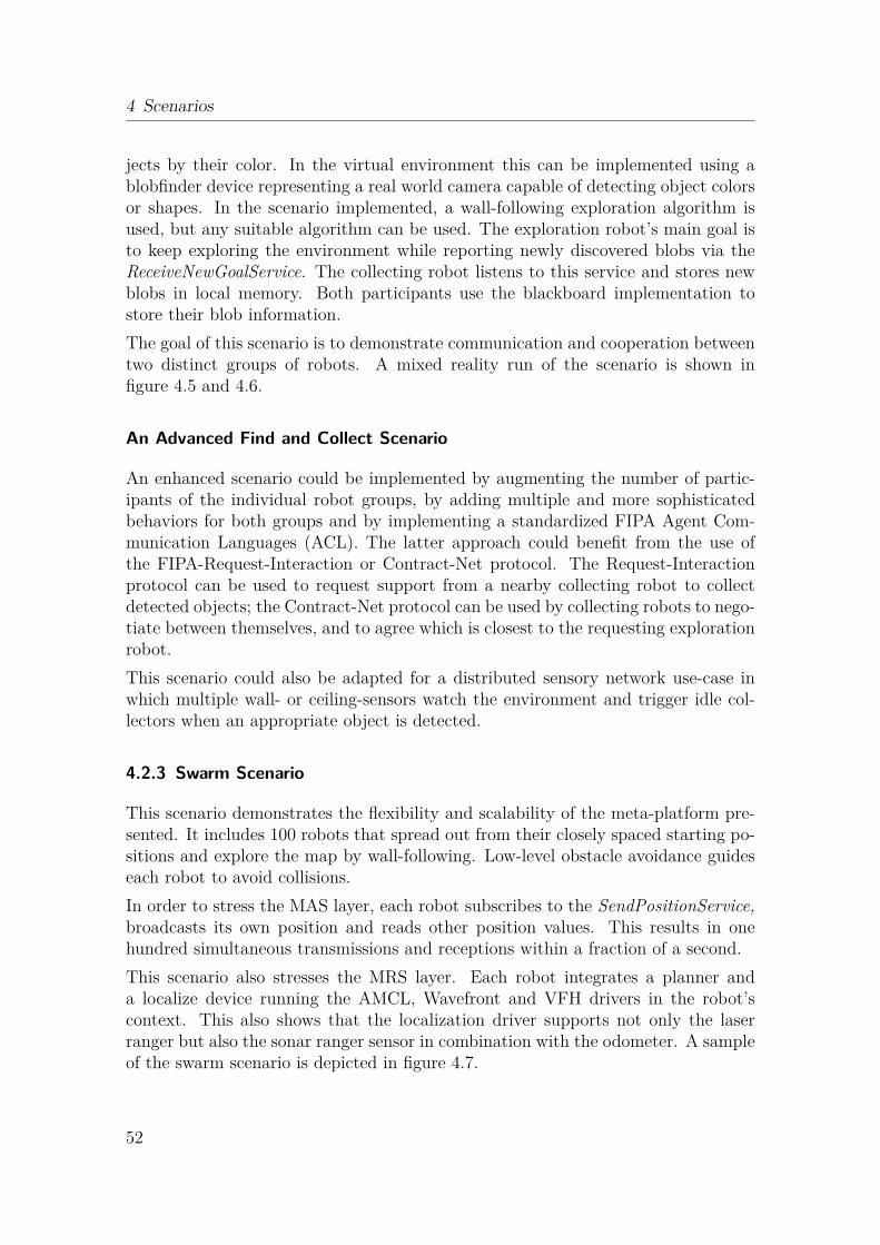
4 Scenarios
jects by their color. In the virtual environment this can be implemented using ablobfinder device representing a real world camera capable of detecting object colorsor shapes. In the scenario implemented, a wall-following exploration algorithm isused, but any suitable algorithm can be used. The exploration robot’s main goal isto keep exploring the environment while reporting newly discovered blobs via theReceiveNewGoalService. The collecting robot listens to this service and stores newblobs in local memory. Both participants use the blackboard implementation tostore their blob information.The goal of this scenario is to demonstrate communication and cooperation betweentwo distinct groups of robots. A mixed reality run of the scenario is shown infigure 4.5 and 4.6.
An Advanced Find and Collect Scenario
An enhanced scenario could be implemented by augmenting the number of partic-ipants of the individual robot groups, by adding multiple and more sophisticatedbehaviors for both groups and by implementing a standardized FIPA Agent Com-munication Languages (ACL). The latter approach could benefit from the use ofthe FIPA-Request-Interaction or Contract-Net protocol. The Request-Interactionprotocol can be used to request support from a nearby collecting robot to collectdetected objects; the Contract-Net protocol can be used by collecting robots to nego-tiate between themselves, and to agree which is closest to the requesting explorationrobot.This scenario could also be adapted for a distributed sensory network use-case inwhich multiple wall- or ceiling-sensors watch the environment and trigger idle col-lectors when an appropriate object is detected.
4.2.3 Swarm Scenario
This scenario demonstrates the flexibility and scalability of the meta-platform pre-sented. It includes 100 robots that spread out from their closely spaced starting po-sitions and explore the map by wall-following. Low-level obstacle avoidance guideseach robot to avoid collisions.In order to stress the MAS layer, each robot subscribes to the SendPositionService,broadcasts its own position and reads other position values. This results in onehundred simultaneous transmissions and receptions within a fraction of a second.This scenario also stresses the MRS layer. Each robot integrates a planner anda localize device running the AMCL, Wavefront and VFH drivers in the robot’scontext. This also shows that the localization driver supports not only the laserranger but also the sonar ranger sensor in combination with the odometer. A sampleof the swarm scenario is depicted in figure 4.7.
52
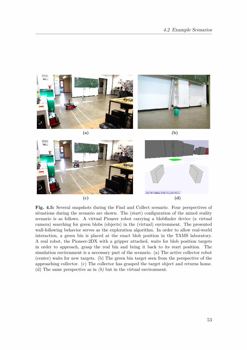
4.2 Example Scenarios
(a) (b)
(c) (d)
Fig. 4.5: Several snapshots during the Find and Collect scenario. Four perspectives ofsituations during the scenario are shown. The (start) configuration of the mixed realityscenario is as follows. A virtual Pioneer robot carrying a blobfinder device (a virtualcamera) searching for green blobs (objects) in the (virtual) environment. The presentedwall-following behavior serves as the exploration algorithm. In order to allow real-worldinteraction, a green bin is placed at the exact blob position in the TAMS laboratory.A real robot, the Pioneer-2DX with a gripper attached, waits for blob position targetsin order to approach, grasp the real bin and bring it back to its start position. Thesimulation environment is a necessary part of the scenario. (a) The active collector robot(center) waits for new targets. (b) The green bin target seen from the perspective of theapproaching collector. (c) The collector has grasped the target object and returns home.(d) The same perspective as in (b) but in the virtual environment.
53
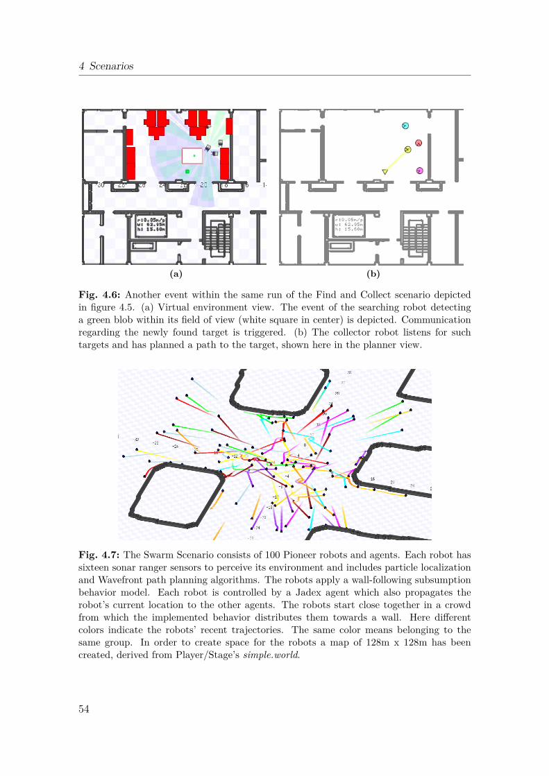
4 Scenarios
(a) (b)
Fig. 4.6: Another event within the same run of the Find and Collect scenario depictedin figure 4.5. (a) Virtual environment view. The event of the searching robot detectinga green blob within its field of view (white square in center) is depicted. Communicationregarding the newly found target is triggered. (b) The collector robot listens for suchtargets and has planned a path to the target, shown here in the planner view.
Fig. 4.7: The Swarm Scenario consists of 100 Pioneer robots and agents. Each robot hassixteen sonar ranger sensors to perceive its environment and includes particle localizationand Wavefront path planning algorithms. The robots apply a wall-following subsumptionbehavior model. Each robot is controlled by a Jadex agent which also propagates therobot’s current location to the other agents. The robots start close together in a crowdfrom which the implemented behavior distributes them towards a wall. Here differentcolors indicate the robots’ recent trajectories. The same color means belonging to thesame group. In order to create space for the robots a map of 128m x 128m has beencreated, derived from Player/Stage’s simple.world.
54
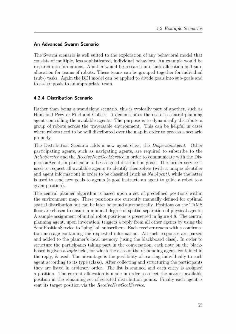
4.2 Example Scenarios
An Advanced Swarm Scenario
The Swarm scenario is well suited to the exploration of any behavioral model thatconsists of multiple, less sophisticated, individual behaviors. An example would beresearch into formations. Another would be research into task allocation and sub-allocation for teams of robots. These teams can be grouped together for individual(sub-) tasks. Again the BDI model can be applied to divide goals into sub-goals andto assign goals to an appropriate team.
4.2.4 Distribution Scenario
Rather than being a standalone scenario, this is typically part of another, such asHunt and Prey or Find and Collect. It demonstrates the use of a central planningagent controlling the available agents. The purpose is to dynamically distribute agroup of robots across the traversable environment. This can be helpful in caseswhere robots need to be well distributed over the map in order to process a scenarioproperly.The Distribution Scenario adds a new agent class, the DispersionAgent. Otherparticipating agents, such as navigating agents, are required to subscribe to theHelloService and the ReceiveNewGoalService in order to communicate with the Dis-persionAgent, in particular to be assigned distribution goals. The former service isused to request all available agents to identify themselves (with a unique identifierand agent information) in order to be classified (such as NavAgent), while the latteris used to send new goals to agents (a goal instructs an agent to guide a robot to agiven position).The central planner algorithm is based upon a set of predefined positions withinthe environment map. These positions are currently manually defined for optimalspatial distribution but can be later be found automatically. Positions on the TAMSfloor are chosen to ensure a minimal degree of spatial separation of physical agents.A sample assignment of initial robot positions is presented in figure 4.8. The centralplanning agent, upon invocation, triggers a reply from all other agents by using theSendPositionService to “ping” all subscribers. Each receiver reacts with a confirma-tion message containing the requested information. All such responses are parsedand added to the planner’s local memory (using the blackboard class). In order tostructure the participants taking part in the conversation, each note on the black-board is given a topic field, for which the class of the responding agent, contained inthe reply, is used. The advantage is the possibility of reacting individually to eachagent according to its type (class). After collecting and structuring the participantsthey are listed in arbitrary order. The list is scanned and each entry is assigneda position. The current allocation is made in order to select the nearest availableposition in the remaining set of selected distribution points. Finally each agent issent its target position via the ReceiveNewGoalService.
55
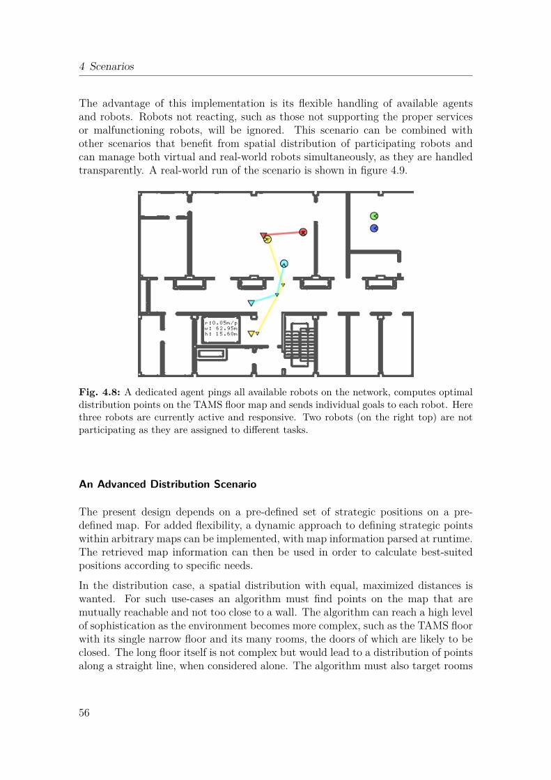
4 Scenarios
The advantage of this implementation is its flexible handling of available agentsand robots. Robots not reacting, such as those not supporting the proper servicesor malfunctioning robots, will be ignored. This scenario can be combined withother scenarios that benefit from spatial distribution of participating robots andcan manage both virtual and real-world robots simultaneously, as they are handledtransparently. A real-world run of the scenario is shown in figure 4.9.
Fig. 4.8: A dedicated agent pings all available robots on the network, computes optimaldistribution points on the TAMS floor map and sends individual goals to each robot. Herethree robots are currently active and responsive. Two robots (on the right top) are notparticipating as they are assigned to different tasks.
An Advanced Distribution Scenario
The present design depends on a pre-defined set of strategic positions on a pre-defined map. For added flexibility, a dynamic approach to defining strategic pointswithin arbitrary maps can be implemented, with map information parsed at runtime.The retrieved map information can then be used in order to calculate best-suitedpositions according to specific needs.
In the distribution case, a spatial distribution with equal, maximized distances iswanted. For such use-cases an algorithm must find points on the map that aremutually reachable and not too close to a wall. The algorithm can reach a high levelof sophistication as the environment becomes more complex, such as the TAMS floorwith its single narrow floor and its many rooms, the doors of which are likely to beclosed. The long floor itself is not complex but would lead to a distribution of pointsalong a straight line, when considered alone. The algorithm must also target rooms
56
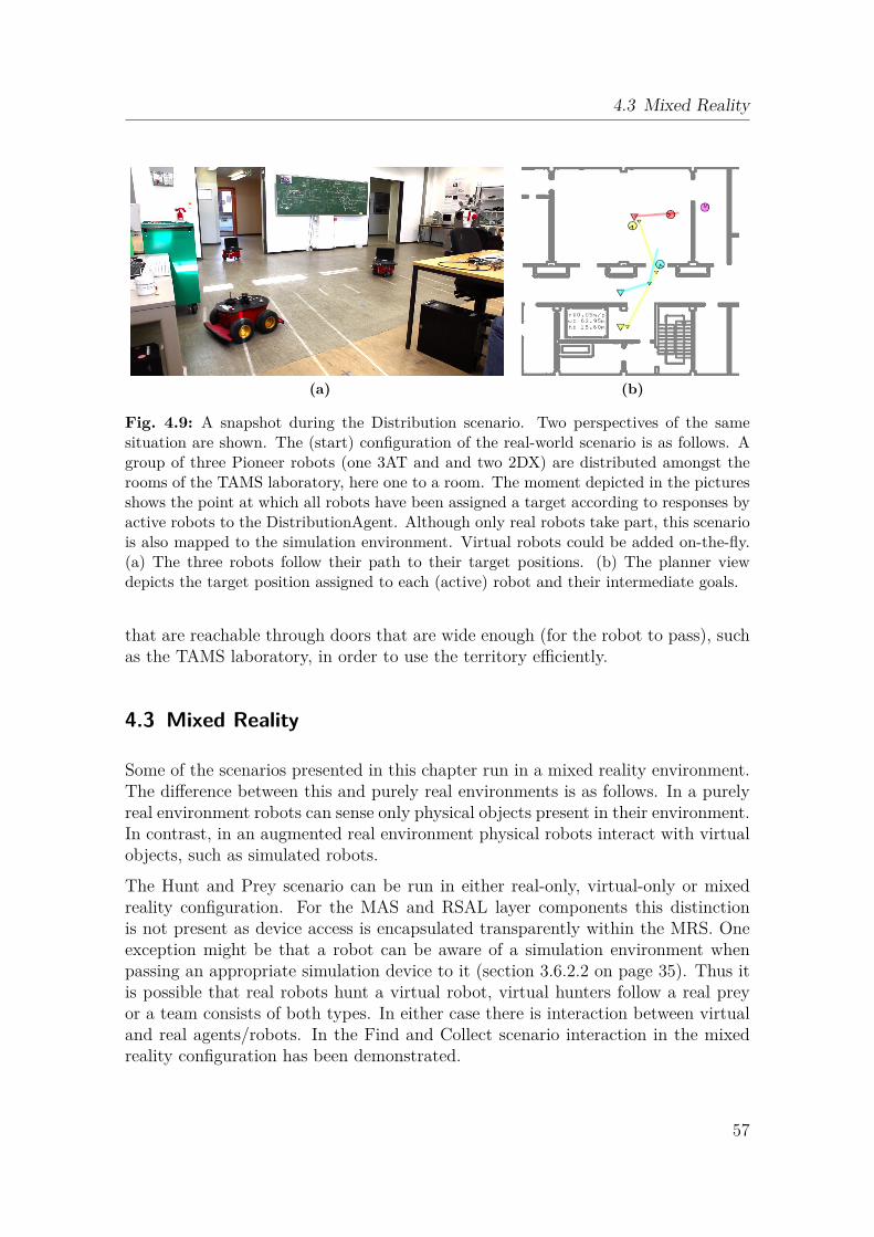
4.3 Mixed Reality
(a) (b)
Fig. 4.9: A snapshot during the Distribution scenario. Two perspectives of the samesituation are shown. The (start) configuration of the real-world scenario is as follows. Agroup of three Pioneer robots (one 3AT and and two 2DX) are distributed amongst therooms of the TAMS laboratory, here one to a room. The moment depicted in the picturesshows the point at which all robots have been assigned a target according to responses byactive robots to the DistributionAgent. Although only real robots take part, this scenariois also mapped to the simulation environment. Virtual robots could be added on-the-fly.(a) The three robots follow their path to their target positions. (b) The planner viewdepicts the target position assigned to each (active) robot and their intermediate goals.
that are reachable through doors that are wide enough (for the robot to pass), suchas the TAMS laboratory, in order to use the territory efficiently.
4.3 Mixed Reality
Some of the scenarios presented in this chapter run in a mixed reality environment.The difference between this and purely real environments is as follows. In a purelyreal environment robots can sense only physical objects present in their environment.In contrast, in an augmented real environment physical robots interact with virtualobjects, such as simulated robots.
The Hunt and Prey scenario can be run in either real-only, virtual-only or mixedreality configuration. For the MAS and RSAL layer components this distinctionis not present as device access is encapsulated transparently within the MRS. Oneexception might be that a robot can be aware of a simulation environment whenpassing an appropriate simulation device to it (section 3.6.2.2 on page 35). Thus itis possible that real robots hunt a virtual robot, virtual hunters follow a real preyor a team consists of both types. In either case there is interaction between virtualand real agents/robots. In the Find and Collect scenario interaction in the mixedreality configuration has been demonstrated.
57
4 Scenarios
A big advantage in such a configuration is the possibility of simulating (robot) hard-ware that is not present in reality, for example where the required number of robots(section 4.2.3) or the required device type (section 4.2.2) is not available. Anotheradvantage is the abstraction from hardware problems. Often an algorithm has beendesigned and needs to be tested. Typically a simulation environment is chosen forinitial testing. Later on, the algorithm is tested on the real hardware. In the lat-ter step, unexpected difficulties often arise as hardware introduces other possibleerrors. In preliminary work (section 2.4) a wall-following algorithm performed wellin the simulation and performed poor in reality (in early development state). Inorder to focus the research effort on the main goal such problems can be avoided byrunning a stable mixed reality environment having only components in reality thatare mature enough. A step-wise approach to migrating each component to reality istransparently possible. Research can focus on the global problem instead of dealingwith low-level (hardware) issues.
4.4 Adoption of another MAS
In order to replace the current MAS with another, the system design allows forseamless migration. Only the top MAS layer within the three layer approach mustbe changed, with changes to the agent implementation and the agent services. As itis unlikely that another MAS supports currently implemented agents, agent bodiesmust be adapted in order to conform to the new system. Furthermore the interactionbetween the agents is crucial to the whole platform and has to be adapted as well.If the new MAS supports the Java language, migration should be straightforward.For a different language the JNI must be used to provide a native language interfaceto the Java middle layer. This JNI wrapper must be provided by the user.
4.5 Adoption of another MRS
The replacement of the MRS affects the bottom layer of the three layer system.Special attention must be focussed on the driver components. The use of ROSas the new MRS would lead to minor changes in this area. Since most driversfrom Player/Stage are also supported and integrated in ROS, no major changes arenecessary. To use the same driver configurations as before, the configurations mustbe converted between Player/Stage and ROS (XML) formats.As components of the middle layer rely upon the MRS interface, these componentshave to be adapted. The RSAL classes affected are those derived from Device, ex-cept for the Robot class. Within these classes the MRS calls are encapsulated andmust be replaced by the appropriate ones from the new system. The concept ofa DeviceNode is abstract and typically does not need adaption, although it might
58
4.6 Summary
have less significance; in Player/Stage, devices are bound to a specific node (a Play-erClient), but this need not be so in other MRS. In systems that are completelypeer-to-peer based, such as ROS, the grouping of devices might be optional andarbitrary.
4.6 Summary
In this chapter, selected cooperative scenarios are described. The chapter is basedon common scenarios in robotic research. Here they are integrated into the meta-platform and demonstrate its maturity. Finally a discussion about the applied mixedreality mode is followed by a description of the process of migration to another MASor MRS.
59

4 Scenarios
60
Conclusion
5The meta-platform developed here provides multi-agent facilities to a group of mo-bile robots. These robots can interoperate within a mixed reality environment andthe platform allows efficient integration of new robots and behaviors. How does thisapproach perform in an objective evaluation?
5.1 Introduction
This chapter evaluates the meta-platform and key aspects of the platform will behighlighted and discussed. General enhancements that can, in the future, improvethe implementation are mentioned. Finally an outlook to possible use-cases of thepresented work is given.
5.2 Evaluation
In this section the demonstration example is evaluated according to various criteria,namely the technology used, the scenarios demonstrated, the user interface and theperformance. Both initial requirements and new features are discussed.
5.2.1 Technology
The technologies used include recent developments in the areas of multi-agent sys-tems (Jadex) and multi-robot systems (Player/Stage). Jadex is a proven, reliableand efficient system for research and industrial purposes1. The Player/Stage projecthas been used by many problem-solving activities in robotics world-wide2. Basedupon these major systems, the implemented abstraction layer (RSAL) benefits fromstability and flexibility. RSAL is implemented in Java, which supports state-of-the-art object-oriented software development. In particular, the RSAL implementation
1http://jadex-agents.informatik.uni-hamburg.de/xwiki/bin/view/Usages/Projects2http://playerstage.sourceforge.net/wiki/PlayerUsers (July 11, 2011)
61
5 Conclusion
is heavily threaded: each robot and device runs in its own thread, handles syn-chronization and provides an asynchronous interface. This approach dynamicallyde-couples platform components and also benefits from current and future multi-core computers.In addition to the major components described above, other implementation aspectsare noteworthy:• Current classes for real-world robots, devices and agents facilitate software
re-use within extended or alternative scenarios;• The callback mechanism in use provides for easy, event-driven, access to RSAL
services by any client;• The blackboard pattern allows easy object storage and retrieval and provides
basic features for a robot-learning architecture. The lightweight implementa-tion does not degrade performance, allowing components, such as agents, tohave their own “memory” in addition to memory distributed across a networkof participants. This could be achieved by a dedicated central agent, withoutphysical representation, concentrating on message exchange between agents,such as the MasterAgent and DispersionAgent (section 3.6.1).
The use of different robot types, or even of similar robots with different deviceconfigurations, often introduces a high platform configuration effort. The presentedimplementation allows for automatic robot device detection. This feature focusseson a tree-node approach where devices are connected to a root node, the DeviceNode.Dynamic retrieval of currently active devices is provided and includes the recognitionof devices that malfunction and can no longer be used. This approach adds a layer ofabstraction above the robot hardware and allows agent design to focus on cognitivefeatures.The mixed reality configuration presented has been implemented using pre-existingcomponents of the platform. These include a device handling a simulation interfaceand an agent that listens on active services to retrieve the information needed toupdate the simulation. This feature benefits from software reuse and provides acompletely new facility. The mixed reality approach is currently an active fieldof robot research. It provides facilities for a graphical user interface, enabling itto display virtual and real robots simultaneously within a simulation environment.The approach can be extended.
5.2.2 Scenarios
The scenarios presented in chapter 4 provide an overview of basic platform features.All scenarios runnable with real robots such as Hunt and Prey, or Find and Collect,demonstrate successful integration of the robot hardware in use. Navigation, as im-plemented, allowed accurate localization within the TAMS laboratory and the whole
62
5.2 Evaluation
floor. The planner worked well with the configuration and hardware. Additionaldevices such as a gripper and robot-mounted laser ranger finder were integratedsuccessfully.
The integration of the MAS demonstrated the seamless coexistence of MAS andMRS platforms. All features of the agent system worked successfully.
The Hunt and Prey scenario shows inter-agent communication as well as basic co-operation. Interaction happens in a dynamic environment applying multiple, state-of-the-art, robotic features such as wall-following, sensor fusion and a subsumptionbehavior architecture. This software performs well, is robust in the case of hard-ware errors (such as erroneous laser readings and hardware defects), and successfullyhandles different hardware configurations.
Whereas the Hunt and Prey scenario focuses on a simple behavioral model of partici-pating agents, in which the behavior of each agent/robot does not change during thescenario, the Find and Collect scenario implements a two-step interaction. The col-lector agents are triggered only upon receipt, via the agent services, of informationdescribing an “interesting” object. Both finders and collectors use local memory thatimplements the blackboard model, thus allowing them to represent an autonomousmodel of the real or simulated world.
The Swarm scenario demonstrates the scalability and stability of the platform ona single host. Each robot consists of an agent component that communicates viaservices, a robot model that uses its own devices and finally the localization andnavigation component of the MRS. This single-robot model is replicated 100 times.In addition, this scenario provides a starting point from which to explore and im-plement dedicated robot swarm behaviors.
5.2.3 User Interface
The user interface provides a multi-window and component focused surface. TheJadex Control Center provides a well arranged user interface to start/stop agentsand scenarios. Runtime parameters can be changed and passed to agents and sophis-ticated agent debugging features can be applied. An optional Java console supportsinformation display and error localization. This is the main interface, as the usertypically interacts at agent/scenario level. Each MAS typically provides its own,optimized interface.
For a more robot-centric view of a scenario, an MRS typically provides a varietyof tools. For watching current robot localizations and planned trajectories, Play-er/Stage provides the Playernav utility. This provides an easy overview of all par-ticipating robots and their goals. Other MRS, such as ROS, provide their own toolsfor visualization, such as the RVIZ utility.
63
5 Conclusion
When working with simulated environments instead of real ones or when applyinga mixed world scenario, the Stage simulator provides a convenient, almost three-dimensional, interface and allows robot data to be visualized. ROS also integratesthe Stage simulation.
5.2.4 Performance
Overall performance depends upon the applied scenario. In general, total process-ing delays are the sum of delays in the MAS, RSAL and MRS layers. The threadeddesign of the RSAL and the flat, optimized, call hierarchy are apparent in the lowoverall impact of the RSAL on total delays. MAS and MRS delays vary accordingto the current state of a scenario. The MAS can produce significant startup delays.However, by creating many services when starting, it can reduce its impact on theoverall delays within a running scenario. The major impact comes from localizationcomponents: calculation of initial pose estimates at startup takes a long time, asno previous positions are known (unless positions are exactly predefined) and manyparticles have to be processed by the localization component. With the currentlyimplemented and optimized configuration, this delay is minimized. Moreover the de-lay is not recognizable during the main scenario processing. The AMCL algorithmused needs very few resources once it has a position estimate, as further updatestake the previous position into account. Nevertheless, the localization and navi-gation components limit overall system responsiveness when many robots operatesimultaneously, such as in the swarm scenario.
5.3 General Remarks
When multiple agents cooperate to solve a task, several key issues have to be consid-ered. The meta-platform provides the basic infrastructure for nearly any task-solvingstrategy and there are usually many possible configurations, each with advantagesand disadvantages. A suitable system configuration is the key to the effective solu-tion of a given problem. The key issues to be considered are highlighted in [Bek05]and are discussed below.When approaching a task, one must consider the jobs each robot has to handle.Can all sub-tasks be managed by the same robot type or are robots with differingcapabilities required? The answers to this question constrain the scenario configu-ration. If all robots are the same, they can be seen transparently, as the physicalrepresentation of an agent that can manage any task. In this case, the selectionof a robot for a task depends only upon robot location. In contrast, where robotsof differing capabilities are used, the selection of a robot for a task depends uponboth robot type and location. Heterogeneous robot teams require additional inter-action and communication effort, which has to be considered in the scenario design.
64
5.3 General Remarks
Homogeneous robot teams require coordination, but are more flexible in terms ofthe specific robot assigned a task. In the scenarios presented, this differentiationcan be understood. The Hunt and Prey and the Swarm scenario are based uponhomogenous robots, whereas the Find and Collect scenario directs a heterogeneousgroup consisting of explorer and collector robots with differing hardware that no-tably changes their use and behavior. Whereas in the homogenous cases the role ofeach participant can be chosen arbitrarily, this is not true in the heterogeneous case.Here the role of each robot type is distinct in terms of its basic usage. The explorerhas a blob-detecting device and no effector to collect anything. Therefore it has tointeract with a supporting collector robot that does not have an optical detectiondevice but instead has a gripper, allowing it to grip, move and release objects. Thetwo groups need each other to complete the task of searching and collecting ob-jects in their environment. The implemented scenario handles this by interactivelytriggering events on the appropriate agent communication channels (services).Another key aspect of cooperative task solving is the control of distributedrobots. Whereas centralized control over multiple participants allows efficient andredundancy-free management, distributed or autonomous control of each robot in-troduces another level of robustness. The central control approach implements adedicated planner that communicates with scenario participants in a peer-to-peermanner. Information retrieval in this case is simple for the planner, as it processesall data anyway. It can collect data and make decisions from experience in orderto control other robots. This design can be exploited for complex scenarios wherea lot of information from different sources must be processed in order to make rea-sonable and time-critical decisions. In contrast, a decentralized design introducesmore responsibilities to individual robots. Each robot has its own goal, resourcesand plans. Coordination is achieved by each robot solving its individual task. Thisapproach requires less complexity from each individual participant than a centralplanner, which reduces the risk of design or implementation failures. Neverthelessthis comes at the cost of adjusting each component in order to integrate a team forcooperative task solving. The implementation introduces a central planner, such asthe distribution agent, which triggers and receives robot data and controls their for-mation according to the number of robots and their positions. A practical scenariowould most likely benefit from a mixed control design.When formations are required for a task, the design has to focus on the question ofloosely or tight-coupled robot teams. Although in the presented scenarios almostno relative robot positions were important, in other scenarios, robots might operateas a group and therefore have to dynamically coordinate relative positions.Environmental and task requirements can introduce constraints on communicationlinks. Whereas in some scenarios it is possible to share all robot information, for ex-ample by broadcasting, in other scenarios such sharing is not allowed or is impossiblebecause of the environment. Good communication should prefer information-hidingto polluting the network with unwanted or unimportant data. Nevertheless infor-
65
5 Conclusion
mation should be available to all receivers that need it.Another key aspect of such a meta-platform is the human-robot interface, or in otherwords, task assignment. How is a task assigned to a group of robots? This topic isrelated to control design: where a central planner is available, it can accept a task,process it and delegate sub-tasks to participating robots. If no such central processis available, the task has to be subdivided in advance in order to delegate sub-tasksdirectly.Finally certain environmental constraints, such as indoor or outdoor territories,introduce special system designs. Furthermore, learning requires its own cognitivecomponents and must be handled at a more abstract level of interaction, as for singlerobots.
5.4 Practical Usage
The meta-platform presented here provides all services to support scenario devel-opment in the field of robotics. The following paragraphs introduce some suitableapplication areas.In the research field of search and rescue robots, interaction becomes mandatory astypical scenarios are too complex to be accomplished by a single robot. A searchoperation benefits from the number of search participants. The deployment areacan be covered in less time with an increased number of robots. In order to effi-ciently cover the environment without re-discovering the same area it is importantto coordinate the robots’ targets dynamically.Swarm formation, a recent research topic, benefits from this work by applying ded-icated formation algorithms to the system.The scenarios presented are based on a pre-defined static map that is availableto planner components. Another scenario would be to explore unknown territoryusing a team of autonomous robots. Present state-of-the-art SLAM algorithms canrobustly map a territory using a single robot system. For a distributed SLAM,new algorithms can be designed and implemented in the meta-platform in order toexploit its communication and data memory facilities and to benefit from a multi-robot team.Communication between a group of agents or robots is another field of currentresearch, one in which efficiency, scalability and flexibility are important topics. Thecurrently implemented service infrastructure can be enhanced in order to explorethese issues.The important service-robot use-case for a foraging population can also take advan-tage of such a highly interactive platform. Different kinds of household robot mightshare information on activities to be performed and on environmental changes, or
66
5.5 Summary
could pass operator requests to the best suited robot. Nevertheless, such complexscenarios can be combined with distributed sensor networks to support data re-trieval by small, fixed sensors (both dedicated or robot-attached) in the domesticenvironment, such as refrigerators and washing machines.
A practical environment for the Find and Collect scenario would be that of a pro-duction line. Unused or rejected parts, as well as trash, are created during manu-facturing. Such parts could be spotted by mobile or fixed sensors, such as cameras.Mobile collectors would be given the spot positions and would autonomously findtheir way to the target, grasp it and bring it to a disposal position before returningto their idle task.
Often certain facilities have to be under permanent surveillance, such as museums,company buildings and military territories. Such a task can be solved by multiplecameras watching the important area. The field of view can be augmented byvarious mobile robots that periodically observe covered territory. In the case of anemergency event, appropriate actions can be triggered, such as sending mobile robotsto the location of the problem. Robots following surveillance routes through indooror outdoor environments could maintain their battery charge state and servicingautonomously, for example by heading to a recharging point when necessary.
5.5 Summary
This work deals with a generic software platform integrating multi-agent technologyand a multi-robot system. It describes the use of the platform for typical cooperativerobotic scenarios. One Pioneer-3AT and two Pioneer-2DX from MobileRobots Inc.serve as the hardware base for real-world applications. The robots have sonar andlaser ranger sensors attached and some have grippers. With the ranger devices, therobots are able to locate their position on a static map in an indoor environment.The gripper is used for object manipulation. The multi-agent system, Jadex, isintegrated for cognitive and task-distribution services. Furthermore, the multi-robotsystem Player/Stage is used to interact with the robot hardware and to provide asimulation environment.
The development of the software is described in figure 3.5. The robot navigationstacks were configured to reach high localization and path planning accuracy withinan indoor environment. For this purpose, a proportional and accurate grid-map ofthe territory was created by a particle-filter-based SLAM algorithm. The require-ments for a generic system integrating MAS and MRS lead to the design of a genericmiddle layer. Implementation and testing use current software design patterns andfocus on run-time efficiency. The middle layer consists of a flexible concept forrobots, behaviors and devices independent of the specific MAS and MRS in use.Moreover agents, communication services and scenarios have been implemented and
67
5 Conclusion
tested. A mixed reality graphical user interface allows simulated and augmented-reality scenarios. The efficiency of the overall system is scalable, allowing for controlof a large number of robots simultaneously.A multi-robot platform with multi-agent technology based on Player/Stage andJadex has been introduced. Core components can be used with other systems ofthe same kind, such as other MAS and MRS. Two real-world scenarios and onevirtual scenario served as the basis for the realization of interactive collaboration.A concluding discussion of current and future research into various topics related tothe meta-platform has been presented.
5.6 Outlook
This section discusses possible improvements to the presented work.In order to augment the currently supported scenarios, additional robot behaviorcan be added. In particular, this might involve higher-level behaviors such as wall-following or exploration. The low-level behaviors, such as obstacle avoidance, pro-vide a generic module that can be used with other behaviors. A completely object-oriented behavioral model that allows new behavioral components to be added orremoved would improve the flexibility and maintainability of the system. Further-more, advanced swarm scenarios would give the system the ability to perform largearea exploration and communication.In the present implementation, the robot system consisting of the MRS and thecentral MAS are invoked manually. For a more dynamic approach, central andlocal systems can be started automatically upon start-up of the robot hardware.Exploiting the Jadex Awareness feature, which allows automatic detection of agentspresent in the network, would enable autonomous agent invocation. When invoked,a default behavior such as wall-following or system monitoring, could enable morerapid reaction to environmental changes. It could also trigger appropriate tasks onthe discovery of interesting objects.The use of standardized, mature and reliable communication protocols, such as theFIPA-Contract-Net, could make maintainability and debugging more transparent.Task assignment is currently encapsulated within pre-defined scenarios. Accordingly,a specific task-solving activity is defined by the choice of dedicated agents that areknown to be able to contribute to the task solution. Another approach to taskassignment is not to define how the task is to be solved but rather to let the (meta-)platform decide. The task description can then be parsed, automatically dividedinto sub-tasks and then assigned to individual robots. The assignment processis influenced by the agents currently available. Considering the Find and Collectscenario, it could be specified that certain objects have to be collected and broughtto a specific position, but not which robot or how many robots take part in solving
68
5.6 Outlook
the task. Another example in the Hunt and Prey scenario would be to define thetask of hunting a certain group of prey robots instead of assigning each robot a task.A straightforward enhancement of the current system would be the exploitationof the BDI cognitive model using Jadex BDI agents instead of the micro agentimplementation. This approach comes with an external definition of agent goals,with plans and sub-plans to solve. It gives a abstract view of the agent goal definitionand allows complex and long term targets to be defined.
69
5 Conclusion
70
Acknowledgements
This thesis would not have been possible without all the people who supported andhelped me.I especially want to thank all employees of the TAMS group who supported me byanswering all my questions and supplied the needed equipment. Particular I amgrateful to Dipl.-Inf. Denis Klimentjew for providing me with uncountable ideas,hints and the support of my master study. Furthermore I like to thank the VSISgroup for assisting me, namely Dr. Alexander Pokahr and Dipl.-Inf. Dirk Bade fortheir time and help.I would like to show my gratitude to my supervisor Prof. Dr. Jianwei Zhang forthe assignment of this work and his confidence in me and the permit to use thelaboratory equipment.Beside my supervisor, I would like to thank my secondary reviewer Dr. LarsBraubach for the takeover of the second opinion and the given guidance.My sincere thanks also goes to Dr. Andreas Mäder for the installation and assistanceof hardware and software equipment and to Tatjana Tetsis for handling all theorganizational things as well as her always happy mood.The following private people I like to thank in particular.For his endless efforts to review this thesis and giving me his professional advices, Iowe my deepest gratitude to my friend William Morris, B.Eng. Hons.I would like to thank my partner Nicole, who was a steady guide, for her inspirationand patience not only during the time of this work but also during the past years.Last but not the least, it is a pleasure to thank my family: my mother Roswithaand Frank as well as my sister Julia for supporting me in numerous ways during mylife.

Bibliography
[AKBF10] M. Ahmed, M.R. Khan, M.M. Billah, and S. Farhana. A collaborativenavigation algorithm for multi-agent robots in autonomous reconnais-sance mission. In Computer and Communication Engineering (ICCCE),2010 International Conference on, pages 1 –6, May 2010.
[BBC+95] Tucker Balch, Gary Boone, Tom Collins, Harold Forbes, Doug MacKen-zie, and Juan Carlos Santamaria. Io, ganymede and callisto – a multia-gent robot trash-collecting team. AI MAGAZINE, 16:16–2, 1995.
[Bek05] George A. Bekey. Systems of robots: from cooperation to swarm behav-ior. IEEE SMC 2005, Hawaii – Computer Science Department, Univer-sity of Southern California, December 2005.
[BPL04] Lars Braubach, Alexander Pokahr, and Winfried Lamersdorf. Jadex: Ashort overview. In Main Conference Net.ObjectDays 2004, pages 195–207, 9 2004.
[BPL05] Lars Braubach, Alexander Pokahr, and Winfried Lamersdorf. Jadex: Abdi agent system combining middleware and reasoning. In M. KluschR. Unland, M. Calisti, editor, Software Agent-Based Applications, Plat-forms and Development Kits, pages 143–168. Birkhäuser-Verlag, 9 2005.Book chapter.
[BRA94] Tucker Balch, Ronald, and C. Arkin. Communication in reactive multi-agent robotic systems. Autonomous Robots, 1:27–52, 1994.
[Bro86] Rodney A. Brooks. A robust layered control system for a mobile robot.IEEE Journal of Robotics and Automation, 2(1):14–23, 1986.
[CDGU10] Cristina Carletti, Maurizio Di;Rocco, Andrea Gasparri, and GiovanniUlivi. A distributed transferable belief model for collaborative topolog-ical map-building in multi-robot systems. In IEEE/RSJ InternationalConference on Intelligent Robots and Systems, IROS 2010, 2010.
[Cer08] E. Cervera. Practical multi-robot applications with player and jade. InControl, Automation, Robotics and Vision, 2008. ICARCV 2008. 10thInternational Conference on, pages 2004 –2009, 2008.
[CMW09] I.Y.-H. Chen, B. MacDonald, and B. Wunsche. Mixed reality simulationfor mobile robots. In Robotics and Automation, 2009. ICRA ’09. IEEEInternational Conference on, pages 232 –237, May 2009.
73
Bibliography
[CND+10] L. Carlone, M.K. Ng, Jingjing Du, B. Bona, and M. Indri. Rao-blackwellized particle filters multi robot slam with unknown initial cor-respondences and limited communication. In Robotics and Automation(ICRA), 2010 IEEE International Conference on, pages 243 –249, May2010.
[GVH03] Brian P. Gerkey, Richard T. Vaughan, and Andrew Howard. The play-er/stage project: Tools for multi-robot and distributed sensor systems. InProceedings of the 11th International Conference on Advanced Robotics(ICAR), Coimbra, Portugal, June 2003.
[KDP09] A. Kottas, A. Drenner, and N. Papanikolopoulos. Intelligent power man-agement: Promoting power-consciousness in teams of mobile robots. InRobotics and Automation, 2009. ICRA ’09. IEEE International Confer-ence on, pages 1140 –1145, May 2009.
[KKF+10] Been Kim, M. Kaess, L. Fletcher, J. Leonard, A. Bachrach, N. Roy, andS. Teller. Multiple relative pose graphs for robust cooperative mapping.In Robotics and Automation (ICRA), 2010 IEEE International Confer-ence on, pages 3185 –3192, may 2010.
[KNT+09] Ryo Kurazume, Yusuke Noda, Yukihiro Tobata, Kai Lingemann, YumiIwashita, and Tsutomu Hasegawa. Laser-based geometric modeling usingcooperative multiple mobile robots. In Robotics and Automation, 2009.ICRA ’09. IEEE International Conference on, pages 3200 –3205, May2009.
[LaV06] S. M. LaValle. Planning Algorithms. Cambridge University Press, Cam-bridge, U.K., 2006. Also available at http://planning.cs.uiuc.edu.
[MAC97] Douglas C. Mackenzie, Ronald C. Arkin, and Jonathan M. Cameron.Multiagent mission specification and execution, 1997.
[MBF10] D. Miklic, S. Bogdan, and R. Fierro. Decentralized grid-based algo-rithms for formation reconfiguration and synchronization. In Roboticsand Automation (ICRA), 2010 IEEE International Conference on, pages4463–4468, may 2010.
[MLW09] R. Mead, R. Long, and J.B. Weinberg. Fault-tolerant formations ofmobile robots. In Intelligent Robots and Systems, 2009. IROS 2009.IEEE/RSJ International Conference on, pages 4805 –4810, 2009.
[PB09] Alexander Pokahr and Lars Braubach. From a research to anindustrial-strength agent platform: Jadex v2. In Hans-Georg FillHans Robert Hansen, Dimitris Karagiannis, editor, Business Ser-vices: Konzepte, Technologien, Anwendungen - 9. Internationale TagungWirtschaftsinformatik (WI 2009), pages 769–778. Österreichische Com-puter Gesellschaft, 2 2009.
74
Bibliography
[PBJ10] Alexander Pokahr, Lars Braubach, and Kai Jander. Unifying agent andcomponent concepts - jadex active components. In In Proceedings of Sev-enth German conference on Multi-Agent System TEchnologieS (MATES-2010), 2010.
[PBL03] Alexander Pokahr, Lars Braubach, and Winfried Lamersdorf. Jadex:Implementing a bdi-infrastructure for jade agents. EXP - in search ofinnovation (Special Issue on JADE), 3(3):76–85, 9 2003.
[PBL05] Alexander Pokahr, Lars Braubach, and Winfried Lamersdorf. Jadex: Abdi reasoning engine. In J. Dix R. Bordini, M. Dastani and A. El FallahSeghrouchni, editors,Multi-Agent Programming, pages 149–174. SpringerScience+Business Media Inc., USA, 9 2005. Book chapter.
[PBWL07] Alexander Pokahr, Lars Braubach, Andrzej Walczak, and WinfriedLamersdorf. Jadex - engineering goal-oriented agents. In F. Bellifemine,G. Caire, and D. Greenwood, editors, Developing Multi-Agent Systemswith JADE, pages 254–258. Wiley & Sons, 1 2007.
[QCG+09] Morgan Quigley, Ken Conley, Brian Gerkey, Josh Faust, Tully B. Foote,Jeremy Leibs, Rob Wheeler, and Andrew Y. Ng. ROS: an open-sourcerobot operating system. In ICRA Workshop on Open Source Software,2009.
[RAB09] C. Rossi, L. Aldama, and A. Barrientos. Simultaneous task subdivi-sion and allocation for teams of heterogeneous robots. In Robotics andAutomation, 2009. ICRA ’09. IEEE International Conference on, pages946 –951, may 2009.
[RG10] Sebastian Rockel and Chen Gang. Mobile robotics project at hamburguniversity, http://www.sebastianrockel.de/irp09/html (checked July 11,2011), 2010.
[RN03] S J Russell and Peter Norvig. Artificial Intelligence, A Modern Approach- 2nd Edition.pdf, volume 82. Prentice Hall, 2003.
[SC09] P.M. Shiroma and M.F.M. Campos. Comutar: A framework for multi-robot coordination and task allocation. In Intelligent Robots and Sys-tems, 2009. IROS 2009. IEEE/RSJ International Conference on, pages4817 –4824, 2009.
[SMKR09] Xueqing Sun, Tao Mao, J.D. Kralik, and L.E. Ray. Cooperative multi-robot reinforcement learning: A framework in hybrid state space. InIntelligent Robots and Systems, 2009. IROS 2009. IEEE/RSJ Interna-tional Conference on, pages 1190 –1196, oct. 2009.
[SN04] Roland Siegwart and Illah R. Nourbakhsh. Introduction to AutonomousMobile Robots. Bradford Book, 2004.
75
Bibliography
[SN10] S. Srivastava and G.C. Nandi. Localization of mobile robots in a net-work using mobile agents. In Computer and Communication Technology(ICCCT), 2010 International Conference on, pages 415 –420, 2010.
[STSI09] Kazuya Suzuki, Tsunamichi Tsukidate, Masahiro Shimizu, and AkioIshiguro. Stable and spontaneous self-assembly of a multi-robotic sys-tem by exploiting physical interaction between agents. In Proceedings ofthe 2009 IEEE/RSJ international conference on Intelligent robots andsystems, IROS’09, pages 4343–4348, Piscataway, NJ, USA, 2009. IEEEPress.
[TvS10] D. Thomas and O. von Stryk. Efficient communication in autonomousrobot software. In Proc. IEEE/RSJ International Conference on Intel-ligent Robots and Systems (IROS), Taipei, Taiwan, Oct. 18 - 22 2010.
[UM09] P. Urcola and L. Montano. Cooperative robot team navigation strategiesbased on an environment model. In Intelligent Robots and Systems, 2009.IROS 2009. IEEE/RSJ International Conference on, pages 4577–4583,Oct. 2009.
[YHTS10] Jing Yuan, Yalou Huang, Tong Tao, and Fengchi Sun. A cooperativeapproach for multi-robot area exploration. In Intelligent Robots andSystems (IROS), 2010 IEEE/RSJ International Conference on, pages1390 –1395, 2010.
76
Appendix
AThis chapter lists additional material related to this work.
I
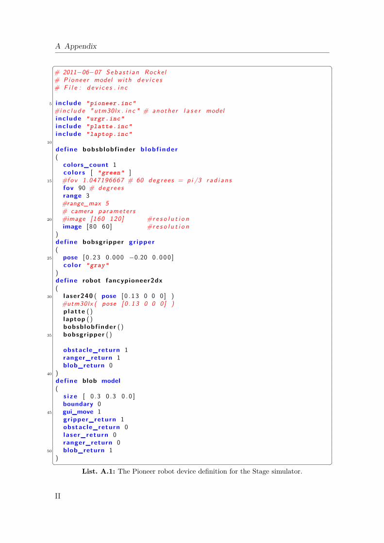
A Appendix
� �# 2011−06−07 S e b a s t i a n Rocke l# P ionee r model w i th d e v i c e s# F i l e : d e v i c e s . i n c
5 i nc lude "pioneer.inc"#i n c l u d e " utm30lx . i n c " # anothe r l a s e r modeli nc lude "urgr.inc"i nc lude "platte.inc"i nc lude "laptop.inc"
10
def ine bobsb lobf inder b lob f inde r(
colors_count 1co lo r s [ "green" ]
15 #fov 1.047196667 # 60 d eg r e e s = p i /3 r a d i a n sfov 90 # d eg r e e srange 3#range_max 5# camera pa ramete r s
20 #image [160 120 ] #r e s o l u t i o nimage [ 80 60 ] #r e s o l u t i o n
)def ine bobsgr ipper gr ipper(
25 pose [ 0 . 2 3 0 .000 −0.20 0 . 0 0 0 ]co lo r "gray"
)def ine robot fancypioneer2dx(
30 l aser240 ( pose [ 0 . 1 3 0 0 0 ] )#utm30lx ( pose [ 0 . 1 3 0 0 0 ] )p la t te ( )laptop ( )bobsb lobf inder ( )
35 bobsgr ipper ( )
obstacle_return 1ranger_return 1blob_return 0
40 )def ine blob model(
s i z e [ 0 . 3 0 .3 0 . 0 ]boundary 0
45 gui_move 1gr ipper_return 1obstacle_return 0l a ser_return 0ranger_return 0
50 blob_return 1)� �
List. A.1: The Pioneer robot device definition for the Stage simulator.
II
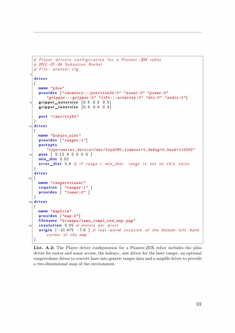
� �# P l a y e r d r i v e r s c o n f i g u r a t i o n f o r a P ionee r−2DX robo t# 2011−07−04 S e b a s t i a n Rocke l# F i l e : p i o n e e r . c f g
4
d r i v e r(
name "p2os"prov ides [ "odometry:::position2d:0" "sonar:0" "power:0"
"gripper:::gripper:0" "lift:::actarray:0" "dio:0" "audio:0" ]9 gr ipper_outers i ze [ 0 . 5 0 .5 0 . 5 ]
gr ipper_ inner s i ze [ 0 . 4 0 .4 0 . 4 ]
port "/dev/ttyS0")
14 d r i v e r(
name "hokuyo_aist"prov ides [ "ranger:1" ]portopts
"type=serial ,device=/dev/ttyACM0 ,timeout=1,debug=0,baud=115200"19 pose [ 0 .13 0 0 0 0 0 ]
min_dist 0 .02er ro r_d i s t 5 .6 # i f range < min_dist , range i s s e t to t h i s v a l u e
)d r i v e r
24 (name "rangertolaser"r equ i r e s [ "ranger:1" ]prov ides [ "laser:0" ]
)29 d r i v e r
(name "mapfile"prov ides [ "map:0" ]f i lename "bitmaps/tams_compl_red_map.png"
34 r e s o l u t i o n 0 .05 # meter s pe r p i x e lo r i g i n [−31.475 −7.8 ] # r e a l−wor ld l o c a t i o n o f the bottom− l e f t −hand
c o r n e r o f the map)� �List. A.2: The Player driver configuration for a Pioneer-2DX robot includes the p2osdriver for motor and sonar access, the hokuyo_aist driver for the laser ranger, an optionalrangertolaser driver to convert laser into generic ranger data and a mapfile driver to providea two-dimensional map of the environment.
III
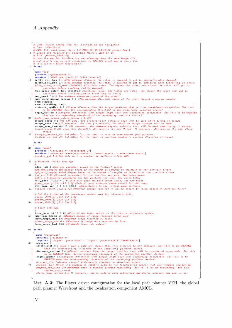
A Appendix
� �# Desc : P l a y e r c o n f i g f i l e f o r l o c a l i z a t i o n and n a v i g a t i o n# Date : 2009−11−16# CVS : $ Id : amcl−sona r . c fg , v 1 . 2 2005−08−05 2 3 : 1 8 : 4 1 ge rkey Exp $
4 # Copied and m o d i f i e d by : S e b a s t i a n Rockel , 2011−06−07# F i l e : p lanner_6666 . c f g# Load the map f o r l o c a l i z a t i o n and p l a n n i n g from the same image f i l e ,# and s p e c i f y the c o r r e c t r e s o l u t i o n ( a 500 x500 p i x e l map at 16m x 16m# i s 0 .032 m / p i x e l r e s o l u t i o n ) .
9 d r i v e r(name " vfh "p r o v i d e s [ " position2d :1" ]r e q u i r e s [ " 6665: position2d :0" " 6665: laser :0" ]
14 safety_dist_0ms 0 .1 #The minimum d i s t a n c e the robo t i s a l l o w e d to ge t to o b s t a c l e s when stopped .safety_dist_1ms 0 .4 #The minimum d i s t a n c e the robo t i s a l l o w e d to ge t to o b s t a c l e s when t r a v e l l i n g at 1 m/ s .#f ree_space_cuto f f_0ms 2000000.0 #U n i t l e s s v a l u e . The h i g h e r the va lue , the c l o s e r the robo t w i l l ge t to
o b s t a c l e s b e f o r e a v o i d i n g ( w h i l e s topped ) .f ree_space_cutoff_1ms 1000000.0 #U n i t l e s s v a l u e . The h i g h e r the va lue , the c l o s e r the robo t w i l l ge t to
o b s t a c l e s b e f o r e a v o i d i n g ( w h i l e t r a v e l l i n g at 1 m/ s ) .max_speed 0 .4 # The maximum a l l o w a b l e speed o f the robo t .
19 max_speed_narrow_opening 0 .1 #The maximum a l l o w a b l e speed o f the robo t through a narrow open ingwhen stopped .when t r a v e l l i n g 1 m/ s .d i s t a n c e _ e p s i l o n 0 .2 #Plana r d i s t a n c e from the t a r g e t p o s i t i o n t h a t w i l l be c o n s i d e r e d a c c e p t a b l e . Set t h i s
to be GREATER than the c o r r e s p o n d i n g t h r e s h o l d o f the u n d e r l y i n g p o s i t i o n d e v i c e !a n g l e _ e p s i l o n 3 #Angula r d i f f e r e n c e from t a r g e t a n g l e t h a t w i l l c o n s i d e r e d a c c e p t a b l e . Set t h i s to be GREATER
than the c o r r e s p o n d i n g t h r e s h o l d o f the u n d e r l y i n g p o s i t i o n d e v i c e !24 #m i n _ t u r n _ r a d i u s _ s a f e t y _ f a c t o r 1 . 0 #??
escape_speed 0 .1 #I f non−zero , the t r a n s l a t i o n a l v e l o c i t y t h a t w i l l be used w h i l e t r y i n g to e scape .escape_time 5 .0 #I f non−zero , the t ime ( i n seconds ) f o r which an escape attempt w i l l be made .escape_max_turnrate 10 #I f non−zero , the maximum a n g u l a r v e l o c i t y t h a t w i l l be used when t r y i n g to e scape .#synch ronous 0 #I f z e r o ( the d e f a u l t ) , VFH runs i n i t s own t h r e a d . I f non−zero , VFH runs i n the main P l a y e r
t h r e a d29 #w e i g h t _ d e s i r e d _ d i r 5 . 0 #Bias f o r the robo t to t u r n to move toward g o a l p o s i t i o n .
#w e i g h t _ c u r r e n t _ d i r 3 . 0 #Bias f o r the robo t to c o n t i n u e moving i n c u r r e n t d i r e c t i o n o f t r a v e l .)d r i v e r(
34 name " amcl "p r o v i d e s [ " localize :0" " position2d :2" ]r e q u i r e s [ " odometry ::6665: position2d :0" " 6665: laser :0" " laser ::6665: map :0" ]
#enab l e_gu i 1 # Set t h i s to 1 to e n a b l e the b u i l t −i n d r i v e r GUI
39 # P a r t i c l e f i l t e r s e t t i n g s#odom_init 0 #Use the odometry d e v i c e as the " a c t i o n " s e n s o r#pf_min_samples 100 #Lower bound on the number o f samples to ma in ta i n i n the p a r t i c l e f i l t e r#pf_max_samples 10000 #Upper bound on the number o f samples to ma in ta i n i n the p a r t i c l e f i l t e r
44 #p f _ e r r 0 .01 #C o n t r o l pa ramete r f o r the p a r t i c l e s e t s i z e . See n o t e s below#pf_z 3 .0 #C o n t r o l pa ramete r f o r the p a r t i c l e s e t s i z e . See no t e s belowi n i t _ p o s e [ −21.0 4 .0 0 ] #I n i t i a l pose e s t i m a t e ( mean v a l u e ) f o r the robo t#i n i t _ p o s e [ −6.0 −5.0 0 . 0 ] #I n i t i a l pose e s t i m a t e ( mean v a l u e ) f o r the robo ti n i t_pose_var [ 3 . 0 3 . 0 3 6 0 . 0 ] #U n c e r t a i n t y i n the i n i t i a l pose e s t i m a t e
49 #update_thre sh [ 0 . 2 0 . 5 2 ] #Minimum change r e q u i r e d i n a c t i o n s e n s o r to f o r c e update i n p a r t i c l e f i l t e r
# Set the 3 rows o f the c o v a r i a n c e mat r i x used f o r odomet r i c d r i f t#odom_dr i f t [ 0 ] [ 0 . 2 0 . 0 0 . 0 ]#odom_dr i f t [ 1 ] [ 0 . 0 0 . 2 0 . 0 ]
54 #odom_dr i f t [ 2 ] [ 0 . 2 0 . 0 0 . 2 ]
# L a s e r s e t t i n g s#l a se r_pose [ 0 . 1 3 0 0 ] #Pose o f the l a s e r s e n s o r i n the robot ’ s c o o r d i n a t e system
59 laser_max_beams 50 #Maximum number o f range r e a d i n g s be i ng usedlaser_range_max 5 .6 #Maximum range r e t u r n e d by l a s e r#l a s e r _ r a n g e _ v a r 0 .1 #Var i ance i n range data r e t u r n e d by l a s e rlaser_range_bad 0 .02 #Probab l e l a s e r min v a l u e s
)64 d r i v e r
(name " wavefront "p r o v i d e s [ " planner :0" ]r e q u i r e s [ " output ::: position2d :1" " input ::: position2d :2" " 6665: map :0" ]
69 alwayson 1s a f e t y _ d i s t 0 .3 #Don ’ t p l an a path any c l o s e r than t h i s d i s t a n c e to any o b s t a c l e . Set t h i s to be GREATER
than the c o r r e s p o n d i n g t h r e s h o l d o f the u n d e r l y i n g p o s i t i o n d e v i c e !d i s t a n c e _ e p s i l o n 0 .4 #Plana r d i s t a n c e from the t a r g e t p o s i t i o n t h a t w i l l be c o n s i d e r e d a c c e p t a b l e . Set t h i s
to be GREATER than the c o r r e s p o n d i n g t h r e s h o l d o f the u n d e r l y i n g p o s i t i o n d e v i c e !a n g l e _ e p s i l o n 10 #Angu la r d i f f e r e n c e from t a r g e t a n g l e t h a t w i l l c o n s i d e r e d a c c e p t a b l e . Set t h i s to be
GREATER than the c o r r e s p o n d i n g t h r e s h o l d o f the u n d e r l y i n g p o s i t i o n d e v i c e !#c s p a c e _ f i l e " p l a n n e r . c space " # C u r r e n t l y d i s a b l e d i n Wavefront d r i v e r
74 #r e p l a n _ d i s t _ t h r e s h 2 .0 #Change i n robot ’ s p o s i t i o n ( i n l o c a l i z a t i o n space ) t h a t w i l l t r i g g e r r e p l a n n i n g#replan_min_t ime 2 .0 #Minimum time i n seconds between r e p l a n n i n g . Set to −1 f o r no r e p l a n n i n g . See a l s o
r e p l a n _ d i s t _ t h r e s h#fo rce_map_re f r e sh 0 # I f non−zero , map i s updated from s u b s c r i b e d map d e v i c e whenever new g o a l i s s e t
)� �List. A.3: The Player driver configuration for the local path planner VFH, the globalpath planner Wavefront and the localization component AMCL.
IV
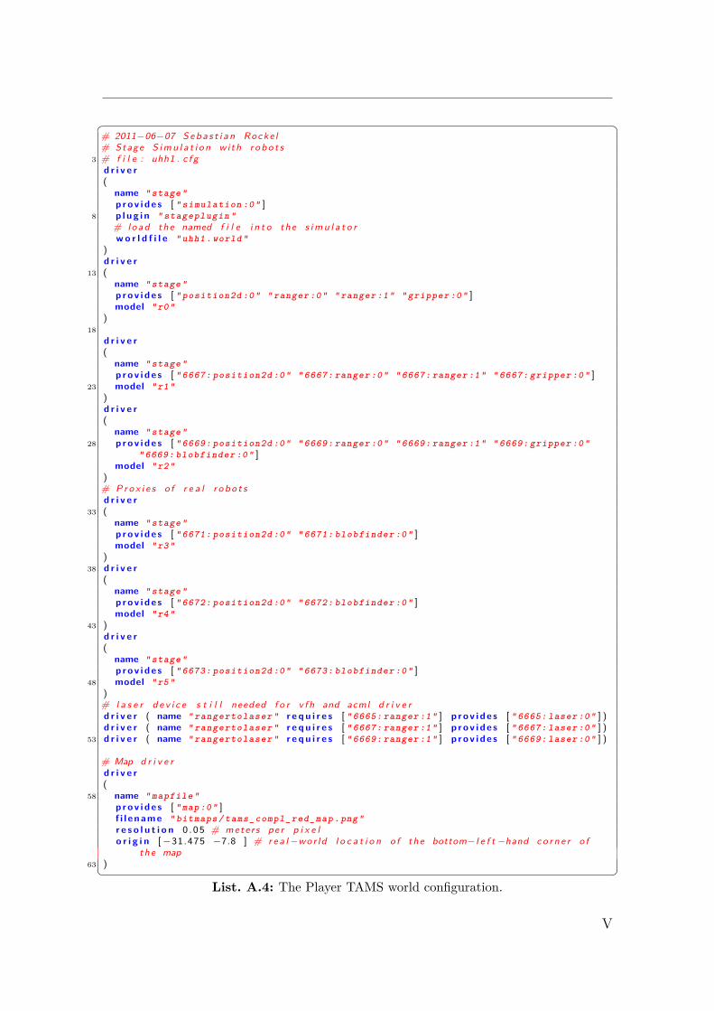
� �# 2011−06−07 S e b a s t i a n Rocke l# Stage S i m u l a t i o n wi th r o b o t s
3 # f i l e : uhh1 . c f gd r i v e r(
name " stage "p r o v i d e s [ " simulation :0" ]
8 p l u g i n " stageplugin "# l o a d the named f i l e i n t o the s i m u l a t o rw o r l d f i l e " uhh1 . world "
)d r i v e r
13 (name " stage "p r o v i d e s [ " position2d :0" " ranger :0" " ranger :1" " gripper :0" ]model "r0"
)18
d r i v e r(
name " stage "p r o v i d e s [ " 6667: position2d :0" " 6667: ranger :0" " 6667: ranger :1" " 6667: gripper :0" ]
23 model "r1")d r i v e r(
name " stage "28 p r o v i d e s [ " 6669: position2d :0" " 6669: ranger :0" " 6669: ranger :1" " 6669: gripper :0"
" 6669: blobfinder :0" ]model "r2"
)# P r o x i e s o f r e a l r o b o t sd r i v e r
33 (name " stage "p r o v i d e s [ " 6671: position2d :0" " 6671: blobfinder :0" ]model "r3"
)38 d r i v e r
(name " stage "p r o v i d e s [ " 6672: position2d :0" " 6672: blobfinder :0" ]model "r4"
43 )d r i v e r(
name " stage "p r o v i d e s [ " 6673: position2d :0" " 6673: blobfinder :0" ]
48 model "r5")# l a s e r d e v i c e s t i l l needed f o r v fh and acml d r i v e rd r i v e r ( name " rangertolaser " r e q u i r e s [ " 6665: ranger :1" ] p r o v i d e s [ " 6665: laser :0" ] )d r i v e r ( name " rangertolaser " r e q u i r e s [ " 6667: ranger :1" ] p r o v i d e s [ " 6667: laser :0" ] )
53 d r i v e r ( name " rangertolaser " r e q u i r e s [ " 6669: ranger :1" ] p r o v i d e s [ " 6669: laser :0" ] )
# Map d r i v e rd r i v e r(
58 name " mapfile "p r o v i d e s [ " map :0" ]f i l e n a m e " bitmaps / tams_compl_red_map .png "r e s o l u t i o n 0 .05 # meter s pe r p i x e lo r i g i n [−31.475 −7.8 ] # r e a l−wor ld l o c a t i o n o f the bottom− l e f t −hand c o r n e r o f
the map63 )� �
List. A.4: The Player TAMS world configuration.
V
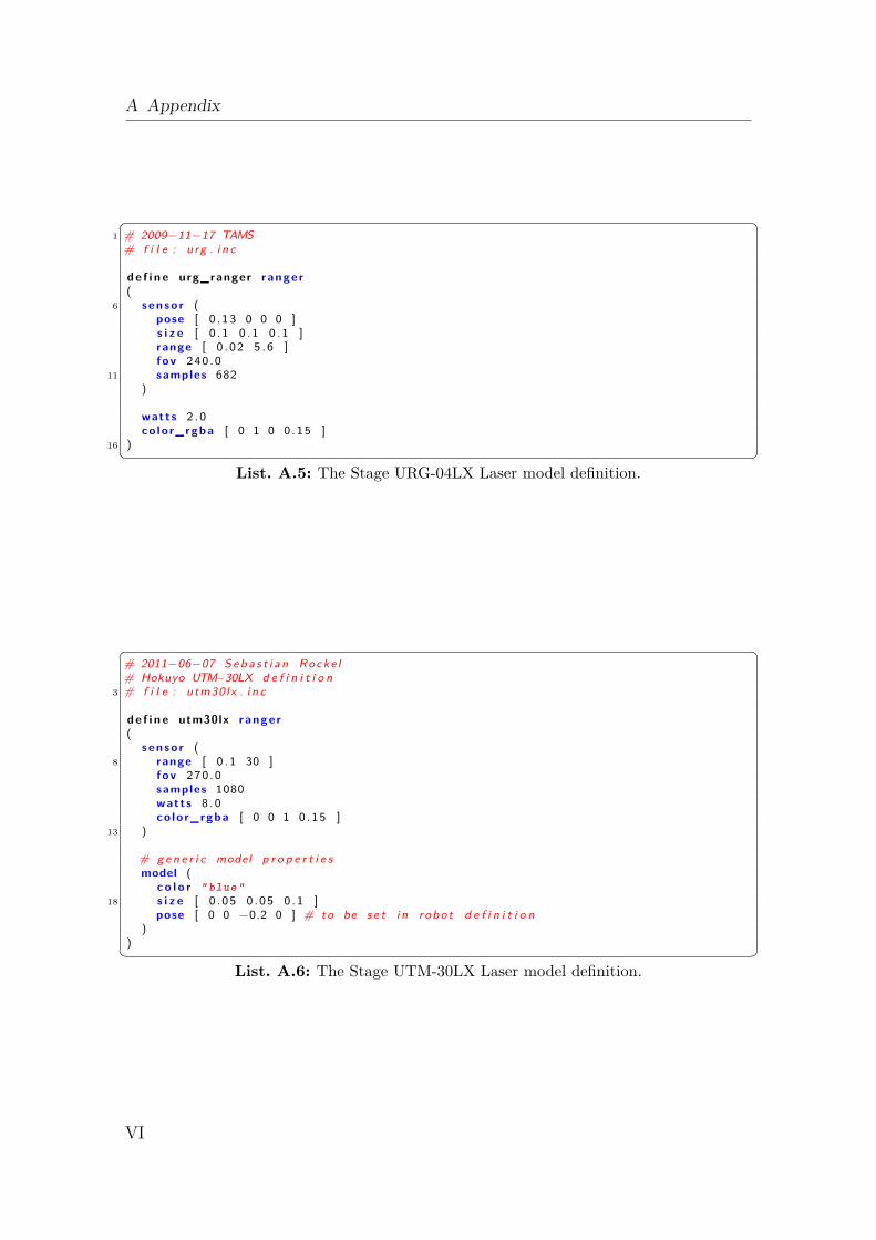
A Appendix
� �1 # 2009−11−17 TAMS
# f i l e : urg . i n c
d e f i n e urg_ranger ranger(
6 s e n s o r (pose [ 0 .13 0 0 0 ]s i z e [ 0 . 1 0 .1 0 .1 ]range [ 0 .02 5 .6 ]fov 240 .0
11 samples 682)
watts 2 .0co lo r_rgba [ 0 1 0 0 .15 ]
16 )� �List. A.5: The Stage URG-04LX Laser model definition.
� �# 2011−06−07 S e b a s t i a n Rocke l# Hokuyo UTM−30LX d e f i n i t i o n
3 # f i l e : utm30lx . i n c
d e f i n e utm30lx ranger(
s e n s o r (8 range [ 0 . 1 30 ]
fov 270 .0samples 1080watts 8 .0co lo r_rgba [ 0 0 1 0 .15 ]
13 )
# g e n e r i c model p r o p e r t i e smodel (
c o l o r " blue "18 s i z e [ 0 .05 0 .05 0 .1 ]
pose [ 0 0 −0.2 0 ] # to be s e t i n robo t d e f i n i t i o n)
)� �List. A.6: The Stage UTM-30LX Laser model definition.
VI
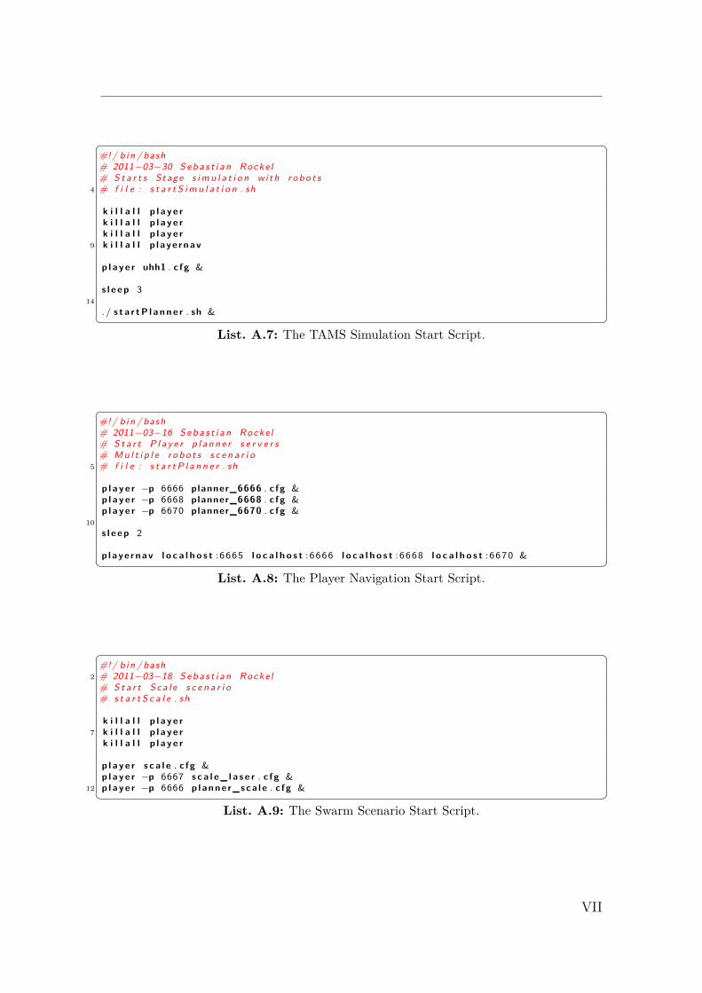
� �#!/ b in / bash# 2011−03−30 S e b a s t i a n Rocke l# S t a r t s Stage s i m u l a t i o n wi th r o b o t s
4 # f i l e : s t a r t S i m u l a t i o n . sh
k i l l a l l p l a y e rk i l l a l l p l a y e rk i l l a l l p l a y e r
9 k i l l a l l p l a y e r n a v
p l a y e r uhh1 . c fg &
s l e e p 314
. / s t a r t P l a n n e r . sh &� �List. A.7: The TAMS Simulation Start Script.
� �#!/ b in / bash# 2011−03−16 S e b a s t i a n Rocke l# S t a r t P l a y e r p l a n n e r s e r v e r s# M u l t i p l e r o b o t s s c e n a r i o
5 # f i l e : s t a r t P l a n n e r . sh
p l a y e r −p 6666 planner_6666 . c fg &p l a y e r −p 6668 planner_6668 . c fg &p l a y e r −p 6670 planner_6670 . c fg &
10s l e e p 2
p l a y e r n a v l o c a l h o s t : 6665 l o c a l h o s t : 6666 l o c a l h o s t : 6668 l o c a l h o s t : 6670 &� �List. A.8: The Player Navigation Start Script.
� �#!/ b in / bash
2 # 2011−03−18 S e b a s t i a n Rocke l# S t a r t S c a l e s c e n a r i o# s t a r t S c a l e . sh
k i l l a l l p l a y e r7 k i l l a l l p l a y e r
k i l l a l l p l a y e r
p l a y e r s c a l e . c fg &p l a y e r −p 6667 s c a l e _ l a s e r . c fg &
12 p l a y e r −p 6666 p l a n n e r _ s c a l e . c fg &� �List. A.9: The Swarm Scenario Start Script.
VII
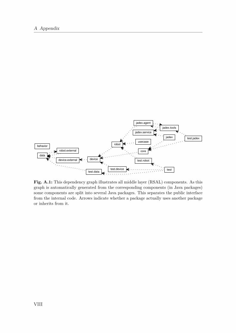
A Appendix
usecase
test.robot
test.jadex
test.devicetest.data
test
robot.external
robot
jadex.tools
jadex.service
jadex.agent
jadex
device.external device
data
core
behavior
Fig. A.1: This dependency graph illustrates all middle layer (RSAL) components. As thisgraph is automatically generated from the corresponding components (in Java packages)some components are split into several Java packages. This separates the public interfacefrom the internal code. Arrows indicate whether a package actually uses another packageor inherits from it.
VIII
Erklärung
Ich, Sebastian Rockel, Matr.-Nr.: 6095961, versichere, dass ich die vorstehende Ar-beit selbstständig und ohne fremde Hilfe angefertigt und mich anderer als der imbeigefügten Verzeichnis angegebenen Hilfsmittel nicht bedient habe. Alle Stellen, diewörtlich oder sinngemäß aus Veröffentlichungen entnommen wurden, sind als solchekenntlich gemacht.Ich bin mit einer Einstellung in den Bestand der Bibliothek des Fachbereichs ein-verstanden.
(Ort, Datum) (Unterschrift)