
A model for Self Pierce Rivet Process of a Boron Steel · For this model a 1454 elements were used,...
12
2016 Science in the Age of Experience 1 http://www.3ds.com/events/science-in-the-age-of-experience A model for Self-Pierce Rivet Process of a Boron Steel Martha P. Guerrero-Mata a , Stephen N. Van Hall b and Kip O. Findley b a Universidad Autónoma de Nuevo León, Facultad de Ingeniería Mecánica y Eléctrica; Av. Universidad s/n, Cd. Universitaria, C.P. 66451; San Nicolás de los Garza, Nuevo León, México b George S. Ansell Department of Metallurgical and Materials Engineering, Colorado School of Mines, Golden, CO 80401, USA Abstract: Self piercing riveting (SPR) is a cold joining technique used in the automotive industry replacing the resistance spot welding. SPR creates a strong mechanical attachment between two or more similar or dissimilar sheets using a semi tubular rivet forge with a die. The number of sheet material combinations is increasing as vehicle design becomes more complex. Improving the mechanical properties of the rivet will enable greater versatility of standard rivet and die combinations. A 3D model of a prototype rivet during forging was developed, different die velocities and material hardness were analyzed aiming to validate the performance of a Boron steel (10B37), focus was set on the rivet, different mesh densities were assessed, the material behavior was input via tensile testing data obtained with wire samples according to ASTM E8 standard, while the die was assumed in all cases analytical rigid, also the influence of friction was studied. The results were validated with data from laboratory trails. The ultimate goal of the model is to develop a method to evaluate material performance and to predict cracking at the tail of the rivet, buckling of the rivet legs and other responses of the rivet in order to achieve an optimal die and punch speed and to correlated the rivet performance with material properties. Keywords: Boron Steel, Self Piercing Riveting. 1. Introduction Two models have been developed using Abaqus/Standard to investigation the SPR process of a10B37 boron steel, a 3D model and an axysimmetric. These models are part of a bigger project being conducted to determine if new rivet alloy solutions could enable a single, standardized rivet geometry and die combination to be used to join multiple different sheet metal stacks in an effort to reduce complexity during manufacture. This commonization attempt is initially being assessed through joining experiments utilizing aluminum alloys and conventional rivet and die combinations. The applicability of SPR technology has become limited by the material properties of the rivet in two main cases: the joining of high strength boron steel to lightweight aluminum and the
Transcript of A model for Self Pierce Rivet Process of a Boron Steel · For this model a 1454 elements were used,...

2016 Science in the Age of Experience 1 http://www.3ds.com/events/science-in-the-age-of-experience
A model for Self-Pierce Rivet Process of a Boron Steel
Martha P. Guerrero-Mataa, Stephen N. Van Hall
b and Kip O. Findley
b
a Universidad Autónoma de Nuevo León, Facultad de Ingeniería Mecánica y Eléctrica; Av.
Universidad s/n, Cd. Universitaria, C.P. 66451; San Nicolás de los Garza, Nuevo León, México
b George S. Ansell Department of Metallurgical and Materials Engineering, Colorado School of
Mines, Golden, CO 80401, USA
Abstract: Self piercing riveting (SPR) is a cold joining technique used in the automotive industry
replacing the resistance spot welding. SPR creates a strong mechanical attachment between two
or more similar or dissimilar sheets using a semi tubular rivet forge with a die. The number of
sheet material combinations is increasing as vehicle design becomes more complex. Improving the
mechanical properties of the rivet will enable greater versatility of standard rivet and die
combinations. A 3D model of a prototype rivet during forging was developed, different die
velocities and material hardness were analyzed aiming to validate the performance of a Boron
steel (10B37), focus was set on the rivet, different mesh densities were assessed, the material
behavior was input via tensile testing data obtained with wire samples according to ASTM E8
standard, while the die was assumed in all cases analytical rigid, also the influence of friction was
studied. The results were validated with data from laboratory trails. The ultimate goal of the
model is to develop a method to evaluate material performance and to predict cracking at the tail
of the rivet, buckling of the rivet legs and other responses of the rivet in order to achieve an
optimal die and punch speed and to correlated the rivet performance with material properties.
Keywords: Boron Steel, Self Piercing Riveting.
1. Introduction
Two models have been developed using Abaqus/Standard to investigation the SPR process of
a10B37 boron steel, a 3D model and an axysimmetric. These models are part of a bigger project
being conducted to determine if new rivet alloy solutions could enable a single, standardized rivet
geometry and die combination to be used to join multiple different sheet metal stacks in an effort
to reduce complexity during manufacture. This commonization attempt is initially being assessed
through joining experiments utilizing aluminum alloys and conventional rivet and die
combinations.
The applicability of SPR technology has become limited by the material properties of the rivet in
two main cases: the joining of high strength boron steel to lightweight aluminum and the

2 2016 Science in the Age of Experience http://www.3ds.com/events/science-in-the-age-of-experience
commonizing of rivet geometries and die combinations across multiple different joint stacks.
Understanding the effect of rivet material properties and the stress states involved during riveting
will provide insight to allow successful joining in these demanding scenarios.
Results from both case studies indicate the formation of fractures along the rivet tail during flaring
into the bottom substrate when the rivet is flared past the available ductility of the current alloy,
10B37. A testing method to evaluate the flaring ability of rivets with the use of a conical die has
been devised and improved to more accurately replicate the rivet failures encountered during
joining attempts.
1.1 Material and Experimental Data
The chemical composition of the a 10B37 boron steel used in presented in Table 1, and Figure 1
shows the mechanical properties obtained by mechanical testing, these were used to feed the
plasticity behavior of the material into the model.
Table 1. Chemical Composition of 10B37 Boron Steel Used in Rivets
wt pct C Mn Si Ni Cr Mo Ti Nb V Al B S P Cu
10B37 0.37 0.76 0.08 0.02 0.28 0.01 0.03 0.01 0.01 0.04 0.004 0.008 0.015 0.01
Figure 1. Uniaxial quasistatic tensile curves for 10B37 wire heat-treated to varying hardness levels.

2016 Science in the Age of Experience 3 http://www.3ds.com/events/science-in-the-age-of-experience
2. Self-Pierce Rivet Finite Element Simulation
Currently in industry, rivet geometry for a specific sheet metal combination is selected based on
historical data and trial and error joining methods. As a result, significant efforts have been put
toward finite element simulations that are able to predict riveting behavior that may be able to
streamline development. Many studies have been performed to correlate rivet deformation profiles
between riveting trials and finite element simulations in an effort to reduce the use of trial and
error methods for determining the best rivet and die combination (Casalino, 2008). Riveting
parameters such as the interlock distance and sheet metal behavior can be accurately predicted by
finite element models in standardized SPR joints where the rivet has little potential for failure.
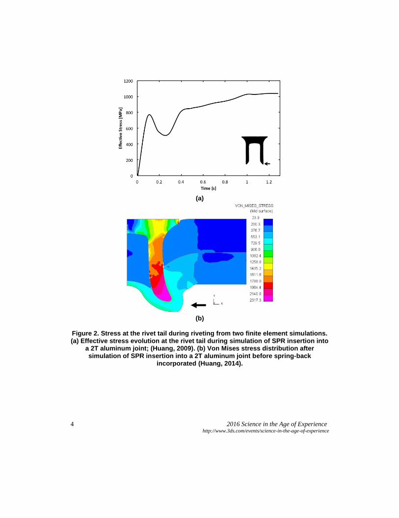
Simulations have shown the development of large stresses at the tail of the rivet that is subjected
to the largest strains during flaring (Huang, 2009, Huang 2014). The location of these large
stresses coincides with the location where fractures develop when rivets are flared beyond design
specifications. Figure 2(a) shows the evolution of effective stress at a point dictated by the arrow
on the rivet cross section as a function of time during a 2T riveting simulation, the stress drop is
indicative of piercing of the top sheet. Figure 2(b) shows the variation of Von Mises stress across
a rivet cross section when a 2T joining simulation is performed, indicating a peak at the point of
interest at the rivet tail, shown by the arrow.
Failure criteria is necessary in finite element simulations to accurately predict the piercing of the
top sheet but is not included for the rivet or lower sheet as the joints modeled are typically not
demanding SPR applications where substrate perforation or rivet failure are expected (Cacko,
2008, Casalino, 2008). Although a failure criteria for the rivet during flaring has not been defined,
there are analogous processes where material is flared, such as cold hole expansion, that provide
insight into the riveting process where ductile failure during flaring is possible and identification
of a failure criterion (Ko, 2007). Figure 3(a) shows the major and minor strains that evolve on two
faces of a plate during a hole expansion test where a 60° die is forced through the hub hole to
perform the expansion. The figure indicates a near uniaxial tensile stress state along the top edge
of the plate, while Figure 3(b) shows the distribution of failure criterion across the flared plate
cross section, indicating the failure criterion is reached at the top edge of the plate during flaring
when the selected criterion, based on Cockroft and Oyane, is reached.
4 2016 Science in the Age of Experience http://www.3ds.com/events/science-in-the-age-of-experience
(a)
(b)
Figure 2. Stress at the rivet tail during riveting from two finite element simulations. (a) Effective stress evolution at the rivet tail during simulation of SPR insertion into
a 2T aluminum joint; (Huang, 2009). (b) Von Mises stress distribution after simulation of SPR insertion into a 2T aluminum joint before spring-back
incorporated (Huang, 2014).

2016 Science in the Age of Experience 5 http://www.3ds.com/events/science-in-the-age-of-experience
(a)
(b)
Figure 3. Strains and failure criterion during cold hole expansion of a wheel hub. (a) Major and minor strain evolution showing the top edge of the plate is near uniaxial tension. (b) Distribution of a ductile failure criterion based on those defined by Cockroft and Oyane predicting failure at the outer rim of the wheel hub (Ko, 2007).
2.1 3D Model
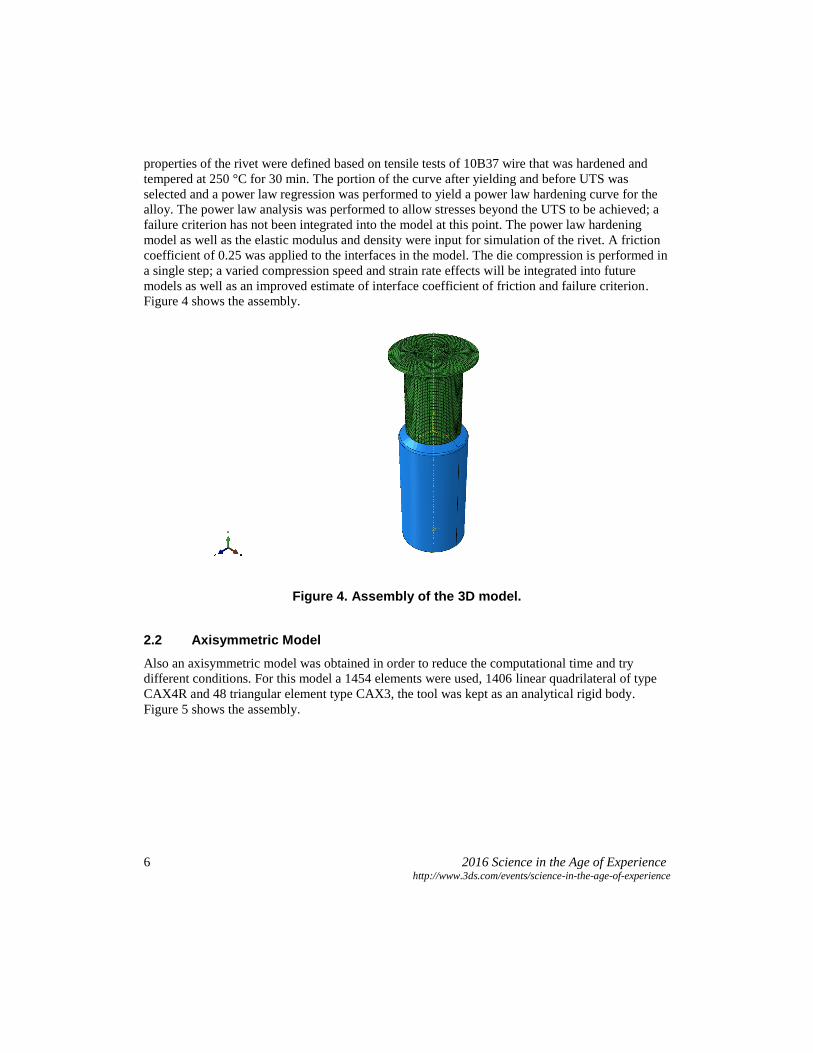
For the 10B37 boron steel finite element simulation of the rivet flaring process using the 120°
conical die was development using Abaqus/Standar. The simulation consists of two parts: the rivet
used in commonization studies and the conical die. Each part was modeled using Solidworks
based on measurements taken from a rivet cross-section using Image J and manual measurements
taken with a micrometer. This model was meshed using Hypermesh; a 51,952 element mesh was
applied to the rivet using C3D8R elements indicating a continuum based 3-dimensional element
with 8 nodes and reduced integration. The rivet head was constrained in 3 dimensions as well as
rotation while the die was moved up the bore of the rivet and treated as a rigid body. The material
6 2016 Science in the Age of Experience http://www.3ds.com/events/science-in-the-age-of-experience
properties of the rivet were defined based on tensile tests of 10B37 wire that was hardened and
tempered at 250 °C for 30 min. The portion of the curve after yielding and before UTS was
selected and a power law regression was performed to yield a power law hardening curve for the
alloy. The power law analysis was performed to allow stresses beyond the UTS to be achieved; a
failure criterion has not been integrated into the model at this point. The power law hardening
model as well as the elastic modulus and density were input for simulation of the rivet. A friction
coefficient of 0.25 was applied to the interfaces in the model. The die compression is performed in
a single step; a varied compression speed and strain rate effects will be integrated into future
models as well as an improved estimate of interface coefficient of friction and failure criterion.
Figure 4 shows the assembly.
Figure 4. Assembly of the 3D model.
2.2 Axisymmetric Model
Also an axisymmetric model was obtained in order to reduce the computational time and try
different conditions. For this model a 1454 elements were used, 1406 linear quadrilateral of type
CAX4R and 48 triangular element type CAX3, the tool was kept as an analytical rigid body.
Figure 5 shows the assembly.

2016 Science in the Age of Experience 7 http://www.3ds.com/events/science-in-the-age-of-experience
Figure 5. Assembly of the axissymetric model.
3. Results
Preliminary finite element simulations of the rivet flaring process have been constructed in order
to define the strain path encountered by the rivet during flaring and to compare that to the strains
evolved during the actual riveting process. A simulation of a 2T aluminum joint was prepared by
Li Huang for Ford Motor Company [2.7] and the strains at the location of interest at the rivet tail
were extracted and plotted as a function of simulation time (stroke distance). The strain curves for
the Ford simulation and the flaring simulation are shown in Figure 2.15(a) and (b), respectively.
Plotting strains against stroke distance indicated the evolution of a strong tensile component in the
Z axis during flaring, as defined by the rivet in Figure 2.15, with compressive strains along the X
and Y axis, as would be expected for a material subjected to a strong uniaxial strain. The X and Y
components differ as a result of the rivet die being filled and providing increasing compressive
stress to the rivet at the end of the stroke. The same procedure was performed with the flaring
simulations constructed in Abaqus® to crosshead displacement levels just beyond those where
failure occurs, 1.67 mm (0.0657 in), and the trends appear to be similar; there is an increasing
positive Z strain with X and Y strains becoming increasingly negative, although at the same rate
which may suggest the strain is purely resultant from the imposed Z (hoop) strain. The rapid
increase in each value after approximately 0.015 s in the Ford study is due to the rivet penetrating
the sheets and the die becoming filled. Also, the strain path in the Ford study is influenced by the

8 2016 Science in the Age of Experience http://www.3ds.com/events/science-in-the-age-of-experience
die shape, which features a contoured pip. A flaring die may be developed which can mimic the
strain path encountered by the rivet during riveting. In addition to comparing the strain path during
the flaring test to the SPR process, Abaqus® simulations show the stress evolution in the rivet
during the flaring process and permit the identification of locations of interest as well as
comparisons with tensile properties. Figure 2.16 shows the Von Mises stress distribution at 0.8
mm crosshead displacement; it can be seen that the Von Mises stress approaches the UTS of the
steel rapidly at the point of fracture initiation at the rivet tail, much earlier than fracture initiates.
(a) (b)
Figure 6. Rivet strains during (a) riveting into a 2T joint stack and (b) flaring over a 120° conical die. Z strains indicate a hoop strain at the rivet tail as a result of flaring. X and Y strains provided by friction and compression,
respectively

2016 Science in the Age of Experience 9 http://www.3ds.com/events/science-in-the-age-of-experience
Figure 7. Von Mises stress distribution from the 3D model for the rivet tail at 0.8 mm (0.0315 in) crosshead displacement. Stress values approach the UTS of the 10B37 steel under investigation
at the point where tail fractures initiate during flaring trials.
Figure 8. Isoparametric view of the Von Mises stress distribution from the 3D model in the rivet tail at 0.8 mm (0.0315 in) crosshead displacement.

10 2016 Science in the Age of Experience http://www.3ds.com/events/science-in-the-age-of-experience
Figure 9. Von Mises stress distribution in the rivet tail using the axisymmetric model.
Figure 10. Plastic equivalente deformation distribution in the rivet tail using the axisymmetric model.

2016 Science in the Age of Experience
11 http://www.3ds.com/events/science-in-the-age-of-experience
4. Conclusions
Abaqus simulations have begun of the rivet flaring process using the commonization rivet
geometry and a 120° conical die. Initial experiments do not include failure criterion but have
integrated the mechanical properties of the rivet through room temperature, quasistatic tensile
testing of the 10B37 wire. Examination of Von Mises stresses indicates a rapid increase past the
UTS of the 10B37 rivet material. The X, Y and Z strains were also defined and compared to those
determined in a SPR process simulation by L. Huang at Ford. Strain evolution appears to proceed
in a similar manner between the SPR and flaring simulations with an increasing Z strain as X and
Y become increasingly compressive where the Z strain is provided by the flaring of the rivet and
the X and Y strains may have a component of friction or compression provided as the die becomes
filled during riveting simulations. Also an axisymmetric model was develop and the results found
Abaqus® simulations will proceed with the goal of determining a robust failure criterion for SPR
flaring through multiple strain paths. Multiple die shapes that mimic SPR strain paths will be
produced and evaluated through simulations and laboratory testing. This will be used to correlate
the failures across multiple rivet geometries, die shapes, and hardness levels to predict a failure
criterion, further simulations to determine the applicability of failure criterion across multiple
microstructures. Digital Image Correlation (DIC) will be performed on the rivet flaring test to
allow further correlation between the Abaqus simulations and laboratory tests. DIC will allow the
measurement of surface strains and allow the modification of the model to better match the strain
evolution in the rivet during flaring. This, combined with the failure criterion previously
mentioned, will increase the validity of the simulation.
5. References
1. Abaqus Users Manual, Version 6.14, Dassault Systémes Simulia Corp., Providence, RI.
2. G. Casalino, A. Rotondo and A. Ludovico, "On the numerical modelling of the multiphysics
self piercing riveting process based on the finite element technique", Advances in Engineering
Software, vol. 39, no. 9, 2008. pp. 787-795.
3. Z. Huang, S. Kang, J. Lai, “Numerical Simulation and Experiment of Self-Piercing Riveting
with Flat-Bottom Die”, International Conference on Transportation Engineering 2009.
4. L. Huang, J. Lasecki, H. Guo and X. Su, "Finite Element Modeling of Dissimilar Metal Self-
piercing Riveting Process", SAE International Journal of Materials and Manufacturing, vol. 7,
no. 3, pp. 698-705, 2014.
5. R. Cacko, "Review of different material separation criteria in numerical modeling of the self-
piercing riveting process – SPR", Archives of Civil and Mechanical Engineering, vol. 8, no. 2,
pp. 21-30, 2008.
6. Y. Ko, J. Lee, H. Huh, H. Kim and S. Park, "Prediction of fracture in hub-hole expanding
process using a new ductile fracture criterion", Journal of Materials Processing Technology,
vol. 187-188, pp. 358-362, 2007.

12 2016 Science in the Age of Experience http://www.3ds.com/events/science-in-the-age-of-experience


![The Role of CAX1 and CAX3 in Elemental Distribution · The Role of CAX1 and CAX3 in Elemental Distribution and Abundance in Arabidopsis Seed1[W][OA] Tracy Punshon*, Kendal Hirschi,](https://static.fdocuments.net/doc/165x107/5d67536a88c993d0688bbc78/the-role-of-cax1-and-cax3-in-elemental-the-role-of-cax1-and-cax3-in-elemental.jpg)


