A model for magnetron sputter deposition using a...
8
1 www.DRAFT.ugent.be A model for magnetron sputter deposition using a rotating cylindrical magnetron K. Van Aeken 1 , S. Mahieu 1 , R. Persoons 2 , D. Depla 1 1 UGent, Gent, Belgium 2 VITO, Mol, Belgium 2 www.draft.ugent.be Magnetron sputter deposition simulations Requirements -On the deposited layers : Thickness and composition uniformity, desired film properties, … -On the magnetron : Target utilization, process stability, power consumption, … Optimization through : -Experiments -Simulation of the sputter deposition process (virtual magnetron) : 1) the magnetron discharge 2) the sputtering from the target 3) the transport of the sputtered particles through the gas phase Introduction Model Discharge Sputtering Transport Experiments Erosion Deposition
Transcript of A model for magnetron sputter deposition using a...
1
www.DRAFT.ugent.be
A model for magnetron sputter
deposition using a rotating cylindrical
magnetron
K. Van Aeken 1, S. Mahieu 1, R. Persoons2, D. Depla 1
1 UGent, Gent, Belgium
2 VITO, Mol, Belgium
2
www.draft.ugent.be
Magnetron sputter deposition simulations
Requirements
-On the deposited layers :
Thickness and composition uniformity, desired film
properties, …
-On the magnetron :
Target utilization, process stability, power consumption,
…
Optimization through :
-Experiments
-Simulation of the sputter deposition process (virtual
magnetron) :
1) the magnetron discharge
2) the sputtering from the target
3) the transport of the sputtered particles through
the gas phase
Introduction
Model
Discharge
Sputtering
Transport
Experiments
Erosion
Deposition

2
3
www.draft.ugent.be
Magnetron sputter deposition simulations
Goal : modeling deposition using a small scale rotating cylindrical
magnetron
Introduction
Model
Discharge
Sputtering
Transport
Experiments
Erosion
Deposition
Approach: Test particle Monte Carlo
- Why ?
- fast
- applicable to large geometries (upscalable)
- straightforward implementation
- But :
- no collective behavior
4
www.draft.ugent.be
Discharge : electron & ion transportIntroduction
Model
Discharge
Sputtering
Transport
Experiments
Erosion
Deposition
Predefined
-> Lorentz-force
High energy electron trajectories :
)()(
BvEqdt
vmd
×+=
BE
,
Anomalous transport (Bohm-diffusion)
--> additional randomizing collisions
Sputter gas
--> elastic, exciting and ionizing collisions
Ion trajectories : assumed collisionless
3
5
www.draft.ugent.be
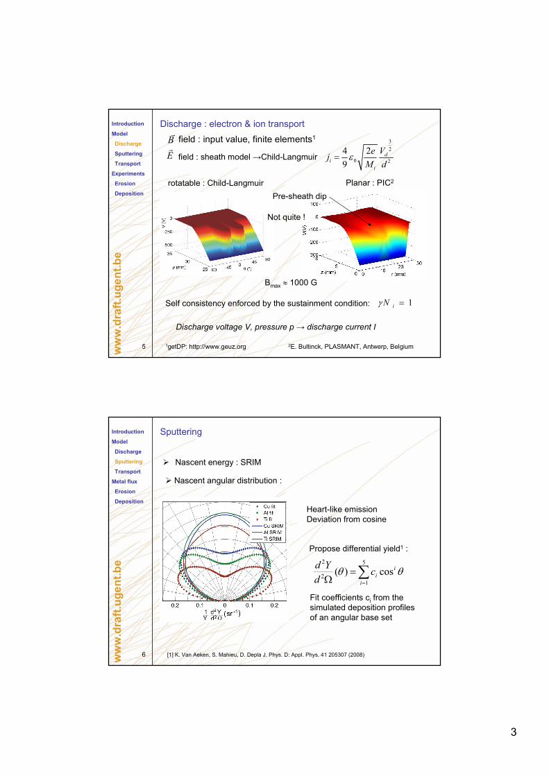
Discharge : electron & ion transport
1getDP: http://www.geuz.org
B
Introduction
Model
Discharge
Sputtering
Transport
Experiments
Erosion
Deposition
field : sheath model →Child-LangmuirE
Self consistency enforced by the sustainment condition: 1=iNγ
3
2
0 2
4 2
9
di
i
Vej
M dε=
Discharge voltage V, pressure p → discharge current I
rotatable : Child-Langmuir Planar : PIC2
2E. Bultinck, PLASMANT, Antwerp, Belgium
Bmax ≈ 1000 G
Pre-sheath dip
Not quite !
field : input value, finite elements1
6
www.draft.ugent.be
SputteringIntroduction
Model
Discharge
Sputtering
Transport
Metal flux
Erosion
Deposition
Heart-like emission
Deviation from cosine
Propose differential yield1 :
∑=
=Ω
5
12
2
cos)(i
i
icd
Ydθθ
Fit coefficients ci from the
simulated deposition profiles
of an angular base set
Nascent energy : SRIM
Nascent angular distribution :
[1] K. Van Aeken, S. Mahieu, D. Depla J. Phys. D: Appl. Phys. 41 205307 (2008)

4
7
www.draft.ugent.be
Gas phase transportIntroduction
Model
discharge
Sputtering
Transport
Experiments
Erosion
Deposition
Assumptions :
sputtered particles are neutral atoms
-> uninfluenced by
only elastic collisions with neutral gas atoms
- ionization degree « 1
- density of sputtered particles « density of gas atoms
Individual collisions :
Interaction potential V(r)
1) screened Coulomb potentials
2) quantum chemical potential for Cu-Ar and Al-Ar2
[1] SImulation of Metal TRAnsport, available at http://www.draft .ugent.be
[2] K.T. Kuwata et al 2003 Nucl. Instr. and Meth. in Phys. Res. B 201 566-70
Advantage : model low energy attractive interaction
+ gas motion → better description of
(near) thermal flux
Implemented in SIMTRA1
BE
,
8
www.draft.ugent.be
Target erosionIntroduction
Model
Discharge
Sputtering
Transport
Experiment
Erosion
Deposition
Measured using optical profilometry :
- cylindrical target mounted on a step motor
- depth profile scanned strip per strip
For accuracy the target depth profile was measured
before sputtering as well -> relative depth = erosion
The magnetic field was varied by changing the vertical (z)-
position of the magnet array with respect to the target
Sputter experiments were carried out under following
conditions :
5560.420.4-10P4
4380.440.4-12P3
3690.440.4-14P2
3690.440.4+14P1
Vd (V)Id (V)P (Pa)Sign(B)z(mm)Name
5
9
www.draft.ugent.be
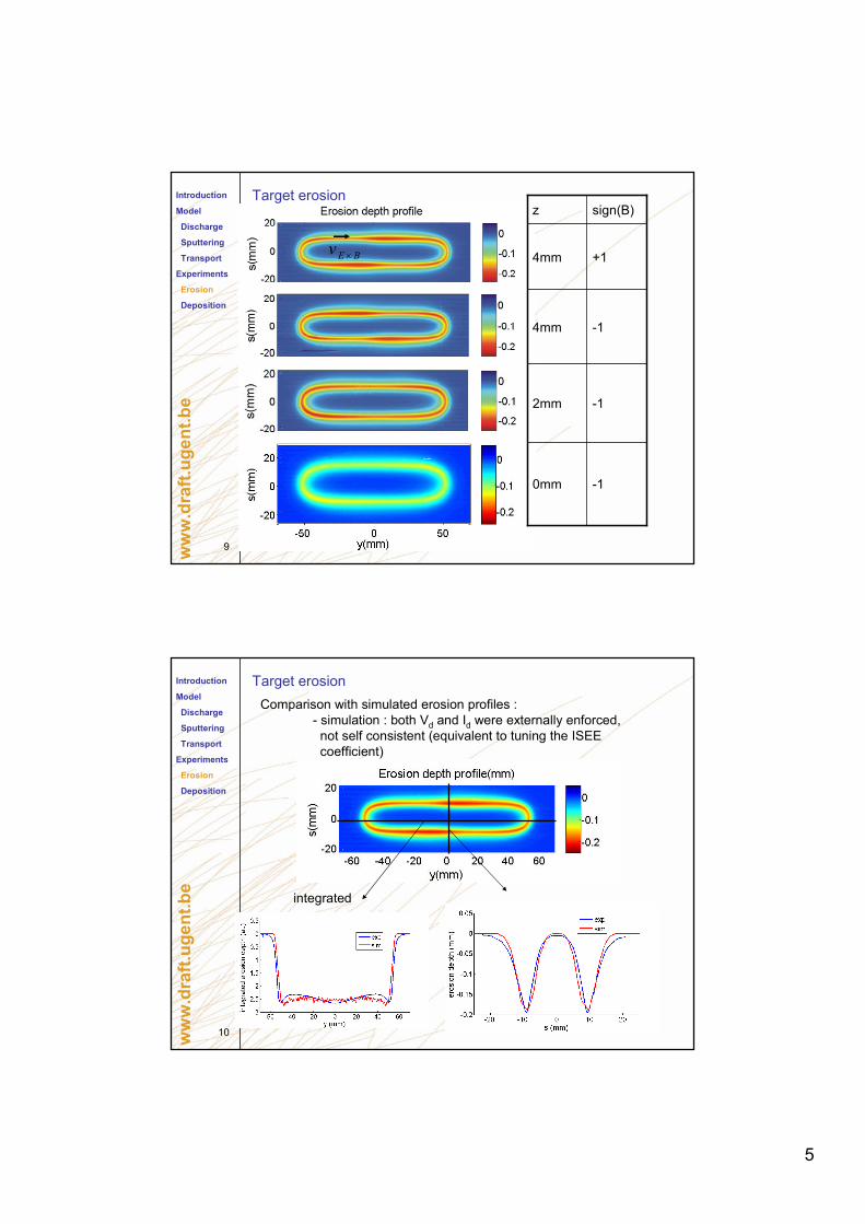
Target erosionIntroduction
Model
Discharge
Sputtering
Transport
Experiments
Erosion
Deposition
-10mm
-12mm
-14mm
+14mm
sign(B)z
E Bv ×
10
www.draft.ugent.be
Target erosion
Comparison with simulated erosion profiles :
- simulation : both Vd and Id were externally enforced,
not self consistent (equivalent to tuning the ISEE
coefficient)
integrated
Introduction
Model
Discharge
Sputtering
Transport
Experiments
Erosion
Deposition

6
11
www.draft.ugent.be
Anomalous transportIntroduction
Model
Discharge
Sputtering
Transport
Experiments
Erosion
Deposition
Bohm-collision
frequency:
B B Lν α ω=
Lω Larmor radius
z = 4mm -> strongest B-field
12
www.draft.ugent.be
Magnetic field dependenceIntroduction
Model
Discharge
Sputtering
Transport
Experiments
Erosion
Deposition
7
13
www.draft.ugent.be
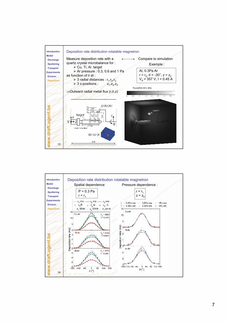
Deposition rate distribution rotatable magnetron
Measure deposition rate with a
quartz crystal microbalance for :
Cu, Ti, Al target
Ar pressure : 0.3, 0.6 and 1 Pa
as function of θ at :
3 radial distances : r1,r2,r3
3 z-positions : z1,z2,z3
⇒Outward radial metal flux (r,θ,z)
Compare to simulation
Al, 0.3Pa Ar
r = r2, θ = -30°, z = z2
Vd = 357 V, I = 0.45 A
Example :
Introduction
Model
Discharge
Sputtering
Transport
Experiments
Erosion
Deposition
14
www.draft.ugent.be
Deposition rate distribution rotatable magnetronIntroduction
Model
Discharge
Sputtering
Transport
Experiments
Erosion
Deposition
P = 0.3 Pa
r = r1
Spatial dependence Pressure dependence :
r = r1
z = z2

8
15
www.draft.ugent.be
Thanks for the attention
Simulation code :
www.draft.ugent.be