Sequestration and Enhanced Coal Bed Methane: Tanquary Farms ...

Adsorption (2011) 17:889–900DOI 10.1007/s10450-011-9357-z
A model for enhanced coal bed methane recovery aimed at carbondioxide storage
The role of sorption, swelling and composition of injected gas
Ronny Pini · Giuseppe Storti · Marco Mazzotti
Received: 9 October 2010 / Accepted: 8 March 2011 / Published online: 24 March 2011© Springer Science+Business Media, LLC 2011
Abstract Numerical simulations on the performance ofCO2 storage and enhanced coal bed methane (ECBM) re-covery in coal beds are presented. For the calculations,a one-dimensional mathematical model is used consistingof mass balances describing gas flow and sorption, anda geomechanical relationship to account for porosity andpermeability changes during injection. Important insightsare obtained regarding the gas flow dynamics during dis-placement and the effects of sorption and swelling on theECBM operation. In particular, initial faster CH4 recov-ery is obtained when N2 is added to the injected mixture,whereas pure CO2 allows for a more effective displace-ment in terms of total CH4 recovery. Moreover, it is shownthat coal swelling dramatically affects the gas injectivity, asthe closing of the fractures associated with it strongly re-duces coal’s permeability. As a matter of fact, injection offlue gas might represent a useful option to limit this prob-lem.
Keywords ECBM · Simulation · Permeability · Sorption ·Swelling
R. Pini (�) · M. MazzottiInstitute of Process Engineering, ETH Zurich, Sonneggstrasse 3,8092 Zurich, Switzerlande-mail: [email protected]
Present address:R. PiniDepartment of Energy Resources Engineering, StanfordUniversity, 367 Panama Street, Stanford, CA 94305, USAe-mail: [email protected]
G. StortiDipartimento di Chimica, Materiali e Ing. Chimica “GiulioNatta”, Sede Mancinelli, Politecnico di Milano, Via Mancinelli 7,20131 Milano, Italy
NotationA Cross sectional area [m2]b Langmuir equilibrium constant [1/Pa]bs Langmuir equilibrium constant (swelling)) [1/Pa]c Gas phase concentration [mol/m3]C1 Effective pressure coefficient [1/Pa]C2 Swelling coefficients [–]F Molar flow rate [mol/day]GIP Original Gas In Place [mol]i Component i
I Amount injected [mol]k Permeability [m2], 1 mD = 9.869233 × 10⁻¹⁶ m2
km Mass transfer coefficient [1/s]kij Interaction parameter (Peng Robinson) [–]L Coal bed length [m]n Adsorbed phase concentration [mol/m3]n∗ Equilibrium adsorbed phase concentration [mol/m3]n∞ Saturation capacity per unit mass adsorbent [mol/g]nc Number of components [–]P Gas phase pressure [Pa]Pc Confining pressure [Pa]Pu Purity [%]R Recovery factor [%]s Volumetric swelling [–]s∞ Saturation capacity (swelling) [–]S Amount stored [mol]t Time [s]T Temperature [°C]u Superficial fluid velocity [m/s]v Interstitial fluid velocity [m/s]w Acentric factor (Peng Robinson) [–]y Gas phase molar fraction [m3/mol]z Axial coordinate [m]
CORE Metadata, citation and similar papers at core.ac.uk
Provided by RERO DOC Digital Library

890 Adsorption (2011) 17:889–900
Greek Lettersα Swelling isotherm coefficient [m3/mol]β Swelling isotherm coefficient [–]ε Fractures (cleats) porosity [–]ε∗ Total porosity [–]εp Macropores porosity [–]μ Dynamic viscosity [Pa.s]ρs Coal bulk density [kg/m3]
1 Introduction
Over the next 20 years from now, natural gas will play akey role in the power sector, mainly because of its availabil-ity and its low carbon content with respect to oil and coal(IEA 2009). At the same time, there is the need to developtechnologies where the produced carbon dioxide (CO2) iscaptured and subsequently stored (Carbon dioxide Captureand Storage, CCS), thus allowing the continued use of fos-sil fuels, while reducing their impact on the increase of at-mospheric CO2 concentration (IPCC 2005). The increasingneed of natural gas has stimulated the exploration of the so-called unconventional gas resources, namely tight sands, gasshales and coal bed methane (CBM) (IEA 2009). Amongthese, the latter is very attractive as the coal seams that haveretained the methane (CH4) for million of years might be ex-ploited as geological storage repositories for CO2. In fact, itis well known from coal mining that significant amounts ofgas can be retained in these reservoirs both by adsorption onthe coal surface as well as by absorption into the coal’s solidmatrix (Rice 1993). Moreover, injection of CO2 into the coalseam would enhance the recovery of CH4, as the former hasa stronger affinity to coal compared to the latter (White et al.2005). This process is called Enhanced Coal Bed Methanerecovery, and, as for enhanced oil recovery, it allows in prin-ciple offsetting the costs associated to the CCS operation(Mazzotti et al. 2009). Moreover, the injection of flue gasinto a coal bed for ECBM recovery might be an attractivealternative to pure CO2 injection for several reasons. First,flue gas is the combustion exhaust gas produced by powerplants, and it could therefore be directly injected, thus avoid-ing the expensive capture step. Secondly, flue gas consistsof mostly nitrogen (87%) and carbon dioxide (13%); thepresence of the weakly adsorbing N2 would allow keepingthe coal permeability sufficiently high (Bustin et al. 2008;Durucan and Shi 2009). This option’s obvious drawbackwould be the need to compress not only CO2 but also ni-trogen before injection.
Observations from the performed field tests evidence thatthe interactions between the gas and the coal need to bebetter understood if ECBM technology has to be deployedat a commercial scale (Gunter et al. 2004; Reeves 2004;Shi et al. 2008; van Bergen et al. 2009). Among these,
gas sorption and swelling have complex effects on the dis-placement dynamics, whose accurate description is essen-tial for the development of reliable reservoir simulators usedto history match field test data obtained from ECBM fieldtests. Input for these models are the results of laboratorystudies that have focused on the different aspects relatedto CO2 storage in coal seams, namely gas sorption (Baeand Bhatia 2006; Day et al. 2008a; Pini et al. 2010), coalswelling (St. George and Barakat 2001; Day et al. 2008b;Ottiger et al. 2008) and permeability changes upon gasinjection (Wang et al. 2007; Mazumder and Wolf 2008;Pini et al. 2009).
One dimensional models have been shown to provide avery useful understanding of the key mechanisms that affectthe storage and recovery process (Gilman and Beckie 2000;Shi and Durucan 2003; Wang et al. 2007; Jessen et al. 2008;Seto et al. 2009). One can distinguish up to four types ofpores in coal, namely cleats where gas and water are present,macro- and mesopores where there is only free gas, andmicropores where adsorption takes place. The general as-sumption is that the displacement of CH4 by CO2 resultsfrom a multistep process. The gas injected in the coal beddiffuses from the fracture network through the matrix andmacropores and finally to the internal surface of the coal.Here, partial pressure with respect to the adsorbed gas is re-duced, causing desorption, and gas exchange takes place.Finally, the desorbed gas diffuses back through the matrixand micropores, out to the fracture network where it flowsto the production well (Gentzis 2000; Totsis et al. 2004).This mass transfer can be described through a linear driv-ing force model by lumping gas diffusion in the differ-ent types of pore using a single mass transfer coefficient,or the corresponding time constant (Bromhal et al. 2005;Sams et al. 2005).
In a previous work, a model was derived that includes thisrelatively simple description of mass transfer complementedby the description of porosity and permeability changes inthe coal during injection. This model was successfully ap-plied for describing pure gas injection experiments into coalcores confined under an external hydrostatic pressure andunder simulated reservoir temperature and pressure condi-tions (Pini et al. 2009).
In the present study, this model is extended to the multi-component single-phase (gas) displacement in a coal seamand numerical simulations estimating the performance ofCO2 storage and ECBM recovery in coal beds are presented.In particular, different ECBM scenarios involving the in-jection of gas mixtures with different composition (frompure N2 to pure CO2) into a coal bed previously saturatedwith methane are investigated. Moreover, emphasis will beplaced on the effects of the sorption-induced swelling on thecoal bed permeability and on its consequences on the CO2
storage operation itself.

Adsorption (2011) 17:889–900 891
2 Modeling
The following assumptions are introduced in the develop-ment of the model: (a) the system is isothermal; (b) allthe mechanical and physicochemical properties are con-stant and homogeneously distributed; (c) the coal behavesas an isotropic linear poroelastic medium; (d) single-phase(gas) flow is considered. The latter assumption is justi-fied by considering the situation where gas injection startsat the end of the so-called primary recovery operation. Infact, during primary recovery almost all the water originallypresent in the reservoir is removed and the remaining frac-tion can be safely considered immobile (Zhu et al. 2003;Durucan and Shi 2009). In the following the two main com-ponents that constitute the model are presented, namely themass balances accounting for gas flow and sorption, and thestress-strain relationship for the description of porosity andpermeability changes during injection.
2.1 Mass balances
Coal reservoirs are fractured systems consisting of a lowpermeability matrix and a high permeability fracture (cleat)network. In this study, the coal total porosity ε∗ is dividedinto cleat porosity ε and macroporosity εp, with the microp-orosity being accounted for as combined with the solid ma-terial, i.e.
ε∗ = ε + (1 − ε)εp (1)
Since the sorption process is assumed to be the rate limitingstep, the gas concentration and pressure in the macroporesand in the fractures are set to be the same. For a system ofnc components, material balances are written for each com-ponent i:
∂(ε∗ci)
∂t+ ∂[(1 − ε∗)ni]
∂t+ ∂(uci)
∂z= 0,
i = 1, . . . , nc (2)
where ci and ni are respectively the actual gas and adsorbedphase concentration of component i, u is the superficial ve-locity, and t and z are time and space coordinates. Note thatin (2) axial dispersion is neglected, as in this study the situa-tion is considered of continuous injection, where a pressuregradient of about 4 MPa across the coal seam exists for thewhole duration of the operation. Under such conditions, dif-fusive effects in the fractures are negligible and the flow isdominated by convection. An conservative analysis of thePeclet number, i.e. the ratio of the characteristic time forconvection to the characteristic time for diffusion, supportsthis conclusion; for the conditions applied in this study and adiffusion coefficient of 10−5 m2/s, the resulting Peclet num-ber takes a value of at least 600, i.e. much larger than one,a situation under which axial mixing can be safely neglected.
A linear driving force model is used to describe the sorp-tion rate of component i through the coal’s matrix, i.e.
∂[(1 − ε∗)ni]∂t
= (1 − ε∗)kmi (n∗i − ni), i = 1, . . . , nc (3)
where kmi is the mass transfer coefficient of component i.The driving force for gas sorption is given by the differ-ence between the equilibrium adsorbed phase concentrationof component i, n∗
i , and the actual concentration of compo-nent i in the adsorbed phase, ni , the former being describedby an equilibrium adsorption isotherm, i.e.
n∗i = ρs
n∞i biyiP
1 + P∑nc
j=1 bjyj
, i = 1, . . . , nc (4)
where n∗i is the adsorbed concentration of component i in
the solid material per unit volume coal, ρs is the adsorbentbulk density, yi is the gas molar fraction and P is the pres-sure; n∞
i and bi are the saturation capacity per unit massadsorbent and the Langmuir equilibrium constant of com-ponent i, respectively.
The superficial velocity u is given by Darcy’s law:
u = vε = − k
μ
(∂P
∂z
)
(5)
where v is the interstitial velocity, k the permeability and μ
the dynamic viscosity.
2.2 Stress-strain relationship
A stress-strain constitutive equation is required to describethe mechanical behavior of the coal bed during the injectionoperation. The fluid pressure in the coal bed plays a decisiverole in determining the stress situation of the reservoir, thusaffecting markedly the porosity and the permeability of theporous medium (Gray 1987; Cui et al. 2007).
First, fractures are closed or widened, depending onwhether the effective pressure on the rock (defined as thelithostatic overburden minus the fluid pressure) is increasedor reduced. Secondly, upon gas sorption the coal swells thusreducing the fracture openings. In the case of coal suchan equation has been shown to take the following generalform (Gilman and Beckie 2000; Shi and Durucan 2004;Bustin et al. 2008):
k
k0=
(ε
ε0
)3
= exp [−C1(Pc − P) − C2s] (6)
where P is the gas pressure, Pc is the confining pressure(lithostatic overburden), s is total swelling, and C1 and C2
are coefficients that depend on coal properties. The subscript0 refers to an arbitrarily chosen initial state. In this study,the reference values of porosity and permeability apply to

892 Adsorption (2011) 17:889–900
an unstressed coal in contact with a non-swelling gas at at-mospheric pressure. It is worth pointing out, that the exper-imental validation of (6) has been recently reported for highpressure gas injection experiments on coal cores confined byan external pressure (Pini et al. 2009).
Several studies have shown that coal swelling can beeffectively described by a Langmuir-like equation (Levine1996; Palmer and Mansoori 1998; Shi and Durucan 2004;Cui et al. 2007; Pini et al. 2009). In an analogous way as forsorption of gas mixtures, an extended Langmuir equation isapplied to coal’s swelling:
si = s∞i bs
i yiP
1 + P∑nc
j=1 bsj yj
, i = 1, . . . , nc (7)
with s∞i and bs
i being the corresponding isotherm parame-ters. To preserve the physical connection between sorptionand swelling, (7) and (4) are combined to obtain an equationexpressing the total swelling as a function of gas sorption,allowing therefore to account for the kinetic of the swellingprocess through the sorption rate given by (3):
s =nc∑
i=1
si =∑nc
i=1 αiβini
1 − ∑ncj=1 αini
(8)
where the parameters αi and βi are functions of the Lang-muir parameters of the sorption and swelling isotherms, i.e.
αi = bi − bsi
ρsn∞i bi
, i = 1, . . . , nc (9a)
βi = bsi s
∞i
bi − bsi
, i = 1, . . . , nc (9b)
Note that (8) is valid for 0 ≤ ni ≤ n∞i .
3 Solution procedure
The problem is defined by (1)–(6) and it is completed bythe following constitutive equations: (a) the Peng-RobinsonEOS, needed to relate gas density to pressure and tempera-ture (Peng and Robinson 1976) and (b) a relationship for thegas mixture viscosity following the method of Wilke (Reidet al. 1987). Initial and boundary conditions are defined asfollows:
Initial conditions: at t = 0, ci = c0i , 0 ≤ z ≤ L
ni = n0i , 0 ≤ z ≤ L
Boundary conditions: at z = 0, ci = cinji , t > 0
at z = L, P = Pout, t > 0
The orthogonal collocation method has been applied to dis-cretize in space the partial differential equations (Villadsen
and Michelsen 1978; Morbidelli et al. 1983). The result-ing system of ordinary differential equations has then beensolved numerically using a commercial ODEs solver (in For-tran).
3.1 Parameters estimation
An extensive set of experimental data for the sorption,swelling and permeability behavior of an Italian coal fromthe Sulcis Coal Province (Sardinia, Italy) has been pro-duced and published (Ottiger et al. 2006; Ottiger et al. 2008;Pini et al. 2009). With reference to the present work, themeasured sorption and swelling isotherms of CO2, CH4 andN2 have been fitted by the Langmuir model and they areshown in Fig. 1. Note that prior fitting the measured excesssorption isotherms have been converted to absolute sorption
Fig. 1 Langmuir sorption (a) and swelling (b) isotherms at 45°C asa function of pressure for CO2 (solid line), CH4 (dashed line) and N2(dotted line) for a coal from the Sulcis coal province
Adsorption (2011) 17:889–900 893
Table 1 Langmuir constants for the sorption and swelling isothermsfor the coal considered in this study
Sorption isotherm Swelling isotherm
n∞i [mol/g] bi [Pa−1] s∞
i [–] bsi [Pa−1]
CO2 2.49 × 10⁻³ 1.25 × 10⁻⁶ 4.90 × 10⁻² 3.80 × 10⁻⁷
CH4 1.56 × 10⁻³ 6.26 × 10⁻⁷ 2.33 × 10⁻² 3.47 × 10⁻⁷
N2 1.52 × 10⁻³ 1.40 × 10⁻⁷ 1.70 × 10⁻² 5.19 × 10⁻⁸
Table 2 Constants C1 (Pa−1) and C2 of (6) as obtained from differentpermeability models
Reference C1 C2
Gilman and Beckie (2000) 3νEf(1−ν)
3EY(1−ν)Ef
Shi and Durucan (2004) 3Cfν(1−ν)
CfEY(1−ν)
Bustin et al. (2008) 1+νKε0(1−ν)
2EY3(1−ν)Kε0
Pini et al. (2009) 3CeKε0
3CsEYKε0
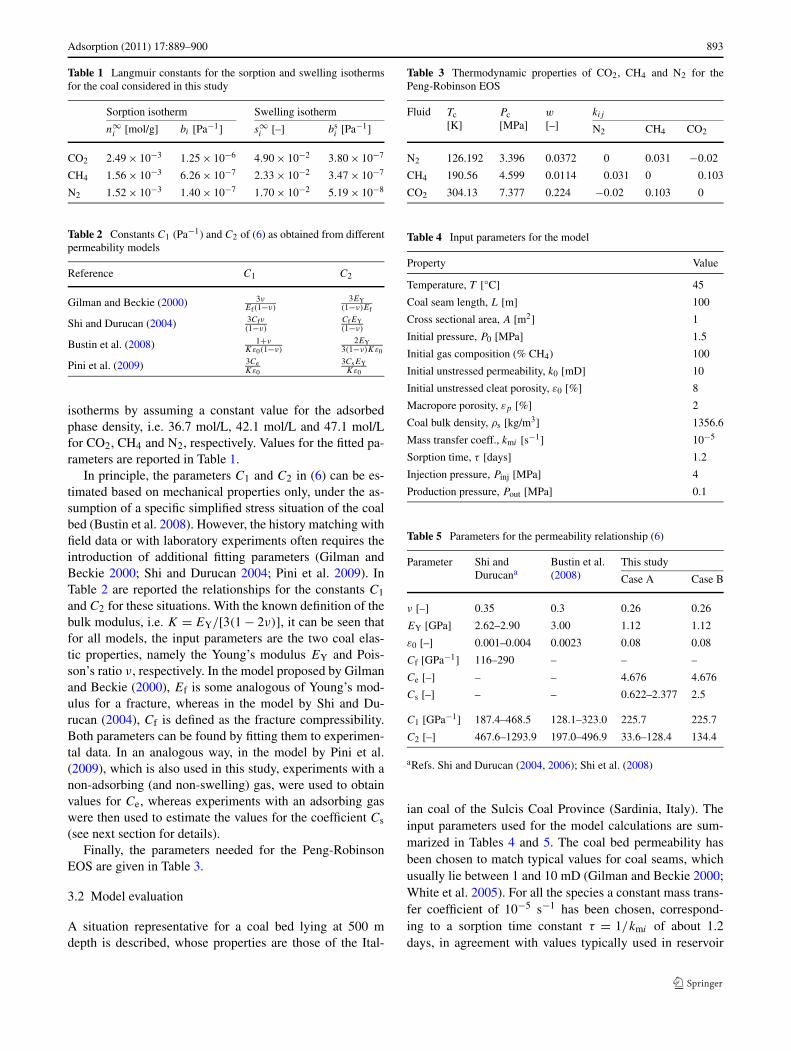
isotherms by assuming a constant value for the adsorbedphase density, i.e. 36.7 mol/L, 42.1 mol/L and 47.1 mol/Lfor CO2, CH4 and N2, respectively. Values for the fitted pa-rameters are reported in Table 1.
In principle, the parameters C1 and C2 in (6) can be es-timated based on mechanical properties only, under the as-sumption of a specific simplified stress situation of the coalbed (Bustin et al. 2008). However, the history matching withfield data or with laboratory experiments often requires theintroduction of additional fitting parameters (Gilman andBeckie 2000; Shi and Durucan 2004; Pini et al. 2009). InTable 2 are reported the relationships for the constants C1
and C2 for these situations. With the known definition of thebulk modulus, i.e. K = EY/[3(1 − 2ν)], it can be seen thatfor all models, the input parameters are the two coal elas-tic properties, namely the Young’s modulus EY and Pois-son’s ratio ν, respectively. In the model proposed by Gilmanand Beckie (2000), Ef is some analogous of Young’s mod-ulus for a fracture, whereas in the model by Shi and Du-rucan (2004), Cf is defined as the fracture compressibility.Both parameters can be found by fitting them to experimen-tal data. In an analogous way, in the model by Pini et al.(2009), which is also used in this study, experiments with anon-adsorbing (and non-swelling) gas, were used to obtainvalues for Ce, whereas experiments with an adsorbing gaswere then used to estimate the values for the coefficient Cs
(see next section for details).Finally, the parameters needed for the Peng-Robinson
EOS are given in Table 3.
3.2 Model evaluation
A situation representative for a coal bed lying at 500 mdepth is described, whose properties are those of the Ital-
Table 3 Thermodynamic properties of CO2, CH4 and N2 for thePeng-Robinson EOS
Fluid Tc[K]
Pc[MPa]
w
[–]kij
N2 CH4 CO2
N2 126.192 3.396 0.0372 0 0.031 −0.02
CH4 190.56 4.599 0.0114 0.031 0 0.103
CO2 304.13 7.377 0.224 −0.02 0.103 0
Table 4 Input parameters for the model
Property Value
Temperature, T [°C] 45
Coal seam length, L [m] 100
Cross sectional area, A [m2] 1
Initial pressure, P0 [MPa] 1.5
Initial gas composition (% CH4) 100
Initial unstressed permeability, k0 [mD] 10
Initial unstressed cleat porosity, ε0 [%] 8
Macropore porosity, εp [%] 2
Coal bulk density, ρs [kg/m3] 1356.6
Mass transfer coeff., kmi [s−1] 10−5
Sorption time, τ [days] 1.2
Injection pressure, Pinj [MPa] 4
Production pressure, Pout [MPa] 0.1
Table 5 Parameters for the permeability relationship (6)
Parameter Shi andDurucana
Bustin et al.(2008)
This study
Case A Case B
ν [–] 0.35 0.3 0.26 0.26
EY [GPa] 2.62–2.90 3.00 1.12 1.12
ε0 [–] 0.001–0.004 0.0023 0.08 0.08
Cf [GPa−1] 116–290 – – –
Ce [–] – – 4.676 4.676
Cs [–] – – 0.622–2.377 2.5
C1 [GPa−1] 187.4–468.5 128.1–323.0 225.7 225.7
C2 [–] 467.6–1293.9 197.0–496.9 33.6–128.4 134.4
aRefs. Shi and Durucan (2004, 2006); Shi et al. (2008)
ian coal of the Sulcis Coal Province (Sardinia, Italy). Theinput parameters used for the model calculations are sum-marized in Tables 4 and 5. The coal bed permeability hasbeen chosen to match typical values for coal seams, whichusually lie between 1 and 10 mD (Gilman and Beckie 2000;White et al. 2005). For all the species a constant mass trans-fer coefficient of 10−5 s−1 has been chosen, correspond-ing to a sorption time constant τ = 1/kmi of about 1.2days, in agreement with values typically used in reservoir

894 Adsorption (2011) 17:889–900
simulators (Bromhal et al. 2005; Shi and Durucan 2005;Shi et al. 2008) and obtained from experiments performedunder similar conditions (Pini et al. 2009). The injectionpressure (Pinj = 4 MPa) is chosen to be slightly lower thanthe hydrostatic pressure corresponding to the coal seamdepth (50 MPa) and the pressure at the production well iskept constant at a value of Pout = 0.1 MPa. Moreover, atthe beginning of the injection, the reservoir pressure (100%CH4) is lower than the hydrostatic pressure and takes a valueof P0 = 1.5 MPa, as might occur after the coal bed primaryproduction.
Two cases have been investigated, which differ in thevalue of the parameter C2 in (6), to highlight the effect ofthe permeability variation on the gas flow dynamics duringthe ECBM process. For “Case A”, the values for the parame-ter Cs,i obtained for each component i from the experimentsreported in Pini et al. (2009) have been used to calculate Cs
defined as the weighted average among the three component,i.e. Cs = ∑nc
i=1 Cs,ixi , with xi being the fractional swelling(si/s). Values of Cs,i used for CO2, CH4 and N2 are 0.623,1.480 and 2.337, respectively. For “Case B”, a four timeslarger value Cs,i has been set for CO2 and has been usedalso for all other components. For this reason, we will re-fer to this situation as the strong swelling case. The value ofthese parameters are summarized in Table 5. For the sake ofcomparison, they are reported together with values given inother studies using a similar stress-strain relationship for thepermeability. It is worth pointing out that the initial poros-ity values used in this work are much larger than those fromother studies. This is mainly due to the fact that the refer-ence condition (0) is different: in our study it refers to a un-stressed state (no confinement, no fluid pressure), whereasin the other studies it refers to the initial reservoir condition,thus taking into account also the overburden stress.
As quantitative indicators to compare the outcomes of thedifferent ECBM simulations, the following variables are de-fined (i =CH4):
GIP = AL[ε∗c0
i + (1 − ε∗)n0i
](10a)
Ri = A∫ t
0 uci |z=L dt
GIP(10b)
Pui = ci |z=L∑nc
j=1 cj |z=L
(10c)
where GIP is the initial gas in place, Ri is the current valueof the fraction of CH4 recovered and Pui is its current pu-rity. In the case of CO2, the following variables are intro-duced (i =CO2):
Ii = A
∫ t
0uci |z=0 dt (11a)
Si = A
∫ L
0
[ε∗ci + (1 − ε∗)ni
]dz (11b)
with Ii and Si being the current amount injected and storedin the coal bed, respectively.
4 Results
4.1 Permeability behavior
By assuming that methane is completely displaced by theinjected gas, the changes in permeability can be analyti-cally estimated with (6) only. Figure 2 shows the obtainedvariations in permeability under different injection schemes(from pure CO2 to pure N2) for Cases A and B. In bothcases the confining pressure (Pc) has been kept constant at avalue of 10 MPa. In the figure, the predicted injection curvesare compared to the primary recovery scenario (pure CH4,dashed line), for which the coal bed situation before start-ing gas injection is marked with a circle. The vertical dottedline at 4 MPa represents a theoretical abandonment scenario,where, at the end of the ECBM operation, the coal seam has
Fig. 2 Permeability ratio k/k0 as a function of pressure P underdifferent injection scenarios (solid lines, Pure CO2, 80:20/CO2:N2,50:50/CO2:N2, 20:80/CO2:N2, pure N2) for Case A (weak swell-ing) (a) and Case B (strong swelling) (b). The dashed line correspondsto the primary recovery scenario (pure CH4) and the empty circle to theinitial condition in the reservoir

Adsorption (2011) 17:889–900 895
been completely filled with the injected gas at a pressurecorresponding to the injection pressure. Qualitatively thereis no difference between Case A and B: pure CO2 injec-tion leads to the strongest reduction in permeability, whereasaddition of N2 to the mixture allows counteracting this ef-fect. At constant pressure, the difference in the permeabil-ity behavior among the different injection scenarios dependson the extent of swelling of the coal, which is fluid depen-dent. Because of the weak sorption and swelling of N2 com-pared to CH4 and CO2 (see Fig. 1), the injection of CO2/N2
mixtures induces less permeability reduction compared topure CO2. For gas mixtures rich in N2, permeability can beeven larger when compared to the initial situation. More-over, due to the larger swelling constant (C2), in Case B thechanges in permeability are more pronounced compared toCase A. In particular, in Case B permeability can either beenhanced or reduced of about one order of magnitude, de-pending on whether pure N2 or CO2 is injected. Finally,in agreement with observation reported in previous stud-ies, for Case A a characteristic minimum in permeabilitycan be clearly seen that is positioned at the so-called re-bound pressure (Palmer and Mansoori 1998; Shi et al. 2008;Pini et al. 2009). For Case B the rebound doesn’t appear inthe pressure range investigated due to the imposed strongerswelling.
In the following, ECBM simulations results are presentedfor which the permeability behavior just described has beenused as an input to the model. First, some important char-acteristic features of gas displacement and storage duringECBM recovery are shown for the case of pure CO2 in-jection (Sect. 4.2). Then, a number of ECBM schemes in-volving the injection of CO2/N2 gas mixtures with differentcomposition are investigated and compared in terms of per-formance of the ECBM/CO2 recovery operation (Sect. 4.3).For the sake of better clarity, Case A has been assumed forthe simulations presented in Sect. 4.2 and 4.3. Finally, theeffect of swelling is investigated and a comparison betweenCases A and B is shown in Sect. 4.4.
4.2 ECBM with pure CO2
The two main peculiarities of the ECBM recovery processare that the adsorption/desorption mechanism taking placecontrols the displacement dynamics and that gas sorption isresponsible for gas storage in coal seams. Figure 3a showsa snapshot of the composition profiles of CO2 (solid line)and CH4 (dashed line) in the coal bed at two different times(16 and 83 days), whereas Fig. 3b shows the correspondingpressure profiles. It can be seen that injection of pure CO2
displaces the CH4 through a relatively sharp front, due tothe higher adsorptivity of the former compared to the lat-ter. Therefore as the preferentially adsorbing CO2 propa-gates through the coal bed, no CH4 is left behind. Moreover,
Fig. 3 ECBM with pure CO2 injection (Case A): composition pro-files (a) and pressure profiles (b) along the coal seam axis calculated attwo different times during CH4 displacement by pure CO2 injection
Fig. 4 Amount of CO2 stored as a function of the amount of CO2 in-jected in the coal bed during CH4 displacement by pure CO2 injection(Case A). The amount of CO2 stored in the reservoir is further classi-fied as free gas (dotted line) and adsorbed gas (gray line)
the shape of the composition profiles remains constant intime, whereas the one of the pressure profiles varies slightlyand shows a characteristic bending at the position of the dis-placement front; the reason for this can be attributed to gasvolume changes associated with the adsorption/desorptionprocess.
Figure 4 shows the amount of CO2 stored in the coal bed(SCO2), as a function of the amount of CO2 injected (ICO2).

896 Adsorption (2011) 17:889–900
It can be seen that as long as breakthrough doesn’t occur theamount of gas stored in the coal bed equals the amount ofgas injected, as it should be just from the point of view ofmass conservation (dashed line). However, at breakthroughthe curve bends and reaches a constant value as adsorptionhas also reached equilibrium and the coal is saturated. Thetime (or amount of gas) needed from breakthrough to reachthis point depends on the value of the mass transfer coef-ficient in (3) and takes a value of zero when local equilib-rium between fluid and adsorbed phase is assumed (Zhu etal. 2003). Finally, it can be seen that indeed the amount ofCO2 adsorbed (gray line) accounts for the majority of thestorage (black line), whereas the contribution of gas storagein the fractures and in the macropores (dotted line) is minor.
4.3 Effects of injected gas composition
Figure 5 shows the composition profiles of CO2, CH4 andN2 along the coal bed axis after 42 days for three differ-ent injection scenarios: pure CO2 (a), 50:50/CO2:N2 (b) andpure N2 (c). It can be seen that, differently from the sharpfront described in the previous section, when pure N2 is in-jected the displacement front is much smoother, with theN2 moving faster than CH4 and overtaking it. Again, thiscan be attributed to the adsorption behavior of the gasesinvolved, as in this case the injected component (N2) ad-sorbs less than the displaced component (CH4). Injection
Fig. 5 Composition profiles of CO2, CH4 and N2 along the coalbed axis for three different injection scenarios: pure CO2 (a),50:50/CO2:N2 (b) and pure N2 (c)
of a CO2/N2 mixture results in the appearance of both theabove mentioned effects, as shown in the central figure.In particular, at the CO2/CH4 front the N2 is enriched inthe fluid phase, the latter being the least adsorbing compo-nent.
Figure 6 shows the flow rates of CO2, CH4 and N2 at theproduction well corresponding to the three different scenar-ios just described. It can be seen that when pure CO2 is in-jected, the CH4 recovery is completed as CO2 breakthroughtakes place, because of the characteristic displacement be-havior described above. On the contrary, gas mixtures con-taining N2 show an early breakthrough of N2. In the case of50:50/CO2:N2 injection, this results in a produced stream ofCH4 polluted with N2, until CO2 breakthrough occurs. It isworth noting that in all cases, the initial rapid decrease inthe rate of produced CH4 is due to the opening of the pro-duction well that leads to a decrease of the pressure fromthe initial value (1.5 MPa) to the imposed boundary con-dition (0.1 MPa). From a practical point of view, the endof the operation in the case of pure CO2 injection is deter-mined by the CO2 breakthrough, whereas in the case of pureN2 injection it will depend on the purity of the producedCH4.
These concepts can be better visualized with the helpof Figs. 7a and 7b, where the produced gas quality (interms of CH4 purity) (a) and the amount of CH4 recov-ered (b) are shown as a function of the cumulative amount
Fig. 6 Flow rates of CO2, CH4 and N2 at the production well as afunction of time for three different injection scenarios: pure CO2 (a),50:50/CO2:N2 (b) and pure N2

Adsorption (2011) 17:889–900 897
Fig. 7 Enhanced coal bed methane recovery: CH4 purity (a) and CH4recovery (b) as a function of the amount of injected gas for differ-ent ECBM schemes with different injection compositions (Pure CO2,80:20/CO2:N2, 50:50/CO2:N2, 20:80/CO2:N2 and pure N2)
of gas injected for different ECBM injection scenarios. Notethat since for these simulations a constant injection pres-sure (Pinj = 4 MPa) boundary condition was imposed, theuse of the cumulative gas injection as the x-coordinate in-stead of time is more appropriate. It can be clearly seenthat addition of N2 into the injected gas results in an in-creased pollution of the methane produced, due to overlap-ping between the N2 injection front and the CH4 desorp-tion front described previously. In the case of pure CO2,the produced gas is pure CH4 until completion of the re-covery process. Moreover, with respect to the amount ofCH4 recovered, injection of N2-rich gas mixtures allows fora faster initial CH4 recovery compared to the case wherepure CO2 is injected. However, the total CH4 recovery isachieved earlier with increasing CO2 content in the feed,as shown by the crossover appearing at large CH4 recov-ery values. This behavior can be explained by the very ef-fective CH4 displacement achieved with CO2 (due to itslarger adsorptivity compared to both CH4 and N2). Resultsthat show a similar crossover have been observed by as-suming constant porosity and permeability and by applyingthe method of characteristics to obtain analytical solutionsof gas transport during ECBM recovery (Zhu et al. 2003;Seto et al. 2009). Here, the slower initial recovery observedwhen CO2-rich mixtures are injected was attributed to a re-duction in the local flow velocity caused by the removal ofCO2 from the fluid (mobile) phase.
Fig. 8 Permeability ratio k/k0 at the injection well as a functionof time for Case B (strong swelling) for different ECBM schemeswith different injection compositions (Pure CO2, 80:20/CO2:N2,50:50/CO2:N2, 20:80/CO2:N2 and pure N2)
4.4 Effects of swelling and permeability
Field tests have shown that CO2 injection yields to in-jectivity problems caused by the reduction in permeability(Gunter et al. 2004; Reeves 2004; van Bergen et al. 2006).Moreover, it is expected that the main loss in permeability isconfined around the injection well, where the CO2 concen-tration is the highest. Figure 8 shows the permeability ratiok/k0 at the injection well (z = 0) as a function of time forCase B during the first 4 days of injection. For pure CO2,the initial permeability takes a value of about 4.4 mD andafter 4 days permeability has dropped down to 0.4 mD, cor-responding to a reduction of about one order of magnitude.For pure N2, the situation is reversed, with almost a doublingof the initial permeability value. The situations where a gasmixture is injected lie between these two limiting cases.
This reduction in permeability can have serious effectson the ECBM operation itself. Figure 9a and 9b show theamount of CO2 injected in the coal bed as a function of timefor the different ECBM schemes for the situations whereswelling is weak (Case A) and strong (Case B), respectively.For Case A, it can be seen that the obtained curves are fan-ning out; this result is not surprising as the use of a CO2-rich mixture clearly leads to an increased amount of CO2 in-jected. However, for Case B the difference between the fourinjection scenarios is much smaller compared to Case A. Inother words, the increase in the CO2 feed concentration isnot reflected into a corresponding larger amount of CO2 in-jected, and this is particularly evident for the pure CO2 casewhen compared to the 80:20/CO2:N2 case. An interestingscenario arises from these results: even if the goal is to max-imize the storage of CO2, it could be more effective to injecta mixture of CO2/N2 instead of pure CO2.

898 Adsorption (2011) 17:889–900
Fig. 9 Amount of CO2 injected as a function of time for Case A(weak swelling) (a) and Case B (strong swelling) (b) for differentECBM schemes with different injection compositions (Pure CO2,80:20/CO2:N2, 50:50/CO2:N2 and 20:80/CO2:N2)
5 Discussion
Gas is retained in coal seam primarily by the mechanismof gas sorption. The results presented in Sect. 4.2 show thatindeed gas sorption accounts for more than 95% of the to-tal amount of CO2 stored in the coal bed. Moreover, sincethe density of gas in the adsorbed state is higher (liquid-like) compared to its corresponding equilibrium density inthe gas phase, adsorption represents a more efficient wayof storage than gas compression. It is usually assumed thatat similar depth and pressure, coal beds may contain 2–4times the amount of gas contained in a conventional gasreservoir (McElhiney et al. 1993). From the point of view ofcoal bed gas production, this gives rise to typical productioncurves that are characterized by low production pressures inorder to allow for significant gas desorption to take place(Schraufnagel 1993). A similar concept can be applied toCO2 storage in coal seams: a significant reservoir pressureloss has to occur before gas desorption from the coal matrixcan actually start; this is particularly true for a Langmuir-likeisotherm, which has been shown to provide an effective de-scription of gas sorption in coal (Pini et al. 2010). Moreover,the gas release from the coal matrix is controlled by the des-orption rate, which for some deep coal beds is determined bysorption times as high as 70 days (McElhiney et al. 1993).In this context, gas sorption represents therefore an obstacle
to gas leakage from these geological formations. This con-clusion is supported by observing that coal bed methane canbe produced today, even if it has been generated during theseam formation, a process which might have taken millionsof years.
The recovery of the CH4 that is naturally present in thecoal bed is achieved through an in situ adsorption/desorptionprocess. In Sect. 4.3 different injection scenarios have beeninvestigated, including the injection of pure CO2, pure N2 ormixtures into a coal bed previously saturated with methane,the latter being attractive as it would allow injecting flue gasdirectly without the expensive CO2 capture step. With re-spect to the recovery of the original gas in place, interestingresults have been obtained in terms of purity and productionrate, which could be understood by looking at the specificadsorption behavior of each component on the coal. When acomponent is chosen that adsorbs more than methane, suchas CO2, the initial recovery is slower, but the displacement ismore effective, thus allowing for a faster total recovery. Onthe contrary, the less adsorbing N2 allows for a fast initialCH4 recovery, despite its earlier breakthrough that pollutesthe produced CH4. From a practical point of view therefore,if one is interested in the recovered methane as a fuel ora technical gas, there is a clear trade-off between the in-cremental methane recovery that can be achieved and thequality of the produced gas. However, if the goal is that ofstoring CO2 that has been captured, then the amount of CO2
that can be injected and stored in the reservoir is of primaryimportance.
The volume change of the coal associated with gas sorp-tion can change substantially the picture just described. Itwas shown in Sect. 4.4 that the strong permeability reductioncaused by the swelling of the coal when exposed to CO2 hasserious implications on the performance of an ECBM oper-ation. In particular, the simulation results for Case B showthat the use of a mixture with composition 80:20/CO2:N2
allows injecting (and therefore storing) a similar amount ofCO2 as when pure CO2 is used. The swelling and the re-sulting closing of the fractures will initially affect the regionclose to the injection well, where the CO2 is the highest,therefore impeding the exploitation of the whole coal bedvolume. In agreement with observations from previous sim-ulation studies (Durucan and Shi 2009), the results obtainedin this work disclose new routes towards several attractiveoptions aimed at tackling the injectivity problem just de-scribed and that need to be further investigated. These in-clude the use of flue gas as a way of keeping the permeabil-ity sufficiently high, as well as the development of designcriteria in terms of configuration of injection and produc-tion wells (multi-well pattern), as a way of maximizing CO2
storage and CH4 recovery.

Adsorption (2011) 17:889–900 899
6 Concluding remarks
In this study, the gas flow dynamics during ECBM re-covery operations have been studied with the help of aone-dimensional mathematical model, consisting of massbalances describing gas flow and sorption, and a geome-chanical relationship for the description of porosity andpermeability changes during injection. Simulation resultsshow that gas injection can indeed enhance methane recov-ery. Moreover, when N2 is injected, an initially much morerapid response in terms of methane recovery is observed,whereas the strong adsorbing CO2 yields for a more effec-tive displacement and therefore for a faster total recovery ofmethane. Coal swelling plays a major role in controlling theECBM recovery process: the closing of the fractures asso-ciated with it strongly reduces coal’s permeability. In thiscontext, flue gas injection might represent an attractive op-tion, as it would keep permeability sufficiently high, with theconstraint that the N2 injection front and the CH4 desorptionfront overlap so as the injected gas pollutes methane muchmore than in the case of pure CO2 injection. The results ofthe present study suggest therefore that there is room for op-timizing the ECBM process depending on whether the ob-jective of the project is to maximize the CO2 storage or themethane recovery.
The 1-D description presented above provides a very use-ful understanding of the key mechanisms that affect thestorage and recovery process. However, the 1-D model pre-sented in this study has to be extended to a 3-D domain, ifthe goal is to history-match field tests data. Moreover, effortsin this direction should account for the presence of water inthe coal bed (multiphase flow), for the complexity of thecoal’s pore structure that impacts also mass transfer mecha-nisms, and finally for the heterogeneity in the chemical andmechanical properties of the coal that is present at the reser-voir scale. When considering innovative injection policies,e.g. direct flue gas injection instead of injection of capturedCO2, a careful economic evaluation that includes the com-pression costs has to be carried out. We believe that in thiscontext the availability of the characterization tools and pro-tocols exploited here and of the 1-D model presented in thiswork will play an important role.
References
Bae, J.S., Bhatia, S.K.: High-pressure adsorption of methane and car-bon dioxide on coal. Energy Fuels 20(6), 2599–2607 (2006)
Bromhal, G.S., Neal Sams, W., Jikich, S., Ertekin, T., Smith, D.H.:Simulation of CO2sequestration in coal beds: The effects of sorp-tion isotherms. Chem. Geol. 217(3–4), 201–211 (2005)
Bustin, R.M., Cui, X.J., Chikatamarla, L.: Impacts of volumetric strainon CO2 sequestration in coals and enhanced CH4recovery. Am.Assoc. Pet. Geol. Bull. 92(1), 15–29 (2008)
Cui, X.J., Bustin, R.M., Chikatamarla, L.: Adsorption-induced coalswelling and stress: Implications for methane production and acidgas sequestration into coal seams. J. Geophys. Res. 112, B10202(2007)
Day, S., Duffy, G., Sakurovs, R., Weir, S.: Effect of coal propertieson CO2sorption capacity under supercritical conditions. Int. J.Greenh. Gas Control 2(3), 342–352 (2008a)
Day, S., Fry, R., Sakurovs, R.: Swelling of Australian coals in super-critical CO2. Int. J. Coal Geol. 74(1), 41–52 (2008b)
Durucan, S., Shi, J.Q.: Improving the CO2 well injectivity and en-hanced coalbed methane production performance in coal seams.Int. J. Coal Geol. 77(1–2), 214–221 (2009)
Gentzis, T.: Subsurface sequestration of carbon dioxide—an overviewfrom an Alberta (Canada) perspective. Int. J. Coal Geol. 43(1–4),287–305 (2000)
Gilman, A., Beckie, R.: Flow of coal-bed methane to a gallery. Transp.Porous Media 41(1), 1–16 (2000)
Gray, I.: Reservoir engineering in coal seams. Part 1. The physical pro-cess of gas storage and movement in coal seams. SPE ReservoirEngineering SPE Paper 12514, 28–34 (1987)
Gunter, W.D., Mavor, M.J., Robinson, J.R.: CO2storage and enhancedmethane production: field testing at the Fenn-Big Valley, Alberta,Canada, with application. In: Rubin, E., Keith, D., Gilboy, C.,Wilson, M., Morris, T., Gale, J., Thambimuthu, K. (eds.) Pro-ceedings of the 7th International Conference on Greenhouse GasControl Technologies, Vancouver, Canada, September 5–9, vol. 1,pp. 413–421 (2004)
IEA: World Energy Outlook—Executive Summary. Paris-Cedex,France (2009)
IPCC: IPCC Special Report on Carbon Dioxide Capture and Storage.Prepared by Working Group III of the Intergovernmental Panelon Climate Change [Metz, B., O. Davidson, H.C. de Coninck,M. Loos, and L.A. Meyer (eds.)]. Cambridge University Press,Cambridge (2005)
Jessen, K., Tang, G.Q., Kovscek, A.: Laboratory and simulation inves-tigation of enhanced coalbed methane recovery by gas injection.Transp. Porous Media 73(2), 141–159 (2008)
Levine, J.: Model study of the influence of matrix shrinkage on abso-lute permeability of coal bed reservoirs. In: Gayer, R., Harris, I.(eds.) Coalbed Methane and Coal Geology, vol. 109, pp. 197–212.Geological Society, London (1996), Special Publication
Mazumder, S., Wolf, K.H.: Differential swelling and permeabilitychange of coal in response to CO2 injection for ECBM. Int. J.Coal Geol. 74(2), 123–138 (2008)
Mazzotti, M., Pini, R., Storti, G.: Enhanced coal bed methane recovery.J. Supercrit. Fluids 47(3), 619–617 (2009)
McElhiney, J.E., Paul, G.W., Young, G.B.C., McCartney, J.A.: Reser-voir engineering aspects of coalbed methane. In: Law, B., Rice, D.(eds.) Hydrocarbons from Coal. AAPG Studies in Geology,vol. 38, pp. 361–372. American Association of Petroleum Geolo-gists, Tulsa (1993)
Morbidelli, M., Servida, A., Storti, G.: Application of the orthogonalcollocation method to some chemical engineering problems. Ing.Chi. Ital. 19(5–6), 46–60 (1983)
Ottiger, S., Pini, R., Storti, G., Mazzotti, M., Bencini, R., Quattroc-chi, F., Sardu, G., Deriu, G.: Adsorption of pure carbon dioxideand methane on dry coal from the Sulcis Coal Province (SW Sar-dinia, Italy). Environ. Prog. 25(4), 355–364 (2006)
Ottiger, S., Pini, R., Storti, G., Mazzotti, M.: Competitive adsorptionequilibria of CO2 and CH4 on a dry coal. Adsorption 14(4–5),539–556 (2008)
Palmer, I., Mansoori, J.: How permeability depends on stress and porepressure in coalbeds: A new model. SPE Reserv. Evalu. Eng. 1(6),539–544 (1998)
Peng, D.Y., Robinson, D.B.: A new two-constant equation of state. Ind.Eng. Chem. Fundam. 15(1), 59–64 (1976)

900 Adsorption (2011) 17:889–900
Pini, R., Ottiger, S., Burlini, L., Storti, G., Mazzotti, M.: Role of ad-sorption and swelling on the dynamics of gas injection in coal.J. Geophys. Res. 114, B04203 (2009)
Pini, R., Ottiger, S., Burlini, L., Storti, G., Mazzotti, M.: Sorption ofcarbon dioxide methane and nitrogen in dry coals at high pressureand moderate temperature. Int. J. Greenh. Gas Control 4(1), 90–101 (2010)
Reeves, S.R.: The Coal-Seq project: Key results from field, laboratory,and modeling studies. In: Rubin, E., Keith, D., Gilboy, C., Wil-son, M., Morris, T., Gale, J., Thambimuthu, K. (eds.) Proceed-ings of the 7th International Conference on Greenhouse Gas Con-trol Technologies, Vancouver, Canada, September 5–9, vol. II,pp. 1399–1403 (2004)
Reid, R.C., Prausnitz, J.M., Poling, B.E.: The Properties of Gases andLiquids, 4th edn. McGraw-Hill, New York (1987)
Rice, D.D.: Composition and origins of coalbed gas. In: Law, B.,Rice, D. (eds.) Hydrocarbons from Coal. AAPG Studies in Ge-ology, vol. 38, pp. 159–184. American Association of PetroleumGeologists, Tulsa (1993)
Sams, W.N., Bromhal, G., Jikich, S., Ertekin, T., Smith, D.H.: Field-project designs for carbon dioxide sequestration and enhancedcoalbed methane production. Energy Fuels 19(6), 2287–2297(2005)
Schraufnagel, R.A.: Coalbed methane production. In: Law, B., Rice, D.(eds.) Hydrocarbons from Coal. AAPG Studies in Geology,vol. 38, pp. 341–359. American Association of Petroleum Geolo-gists, Tulsa (1993)
Seto, C.J., Jessen, K., Orr, F.M., Jr.: A multicomponent two-phase-flowmodel for CO2 storage and enhanced coalbed-methane recovery.Soc. Pet. Eng. J. 14(1), 30–40 (2009)
Shi, J.Q., Durucan, S.: A bidisperse pore diffusion model for methanedisplacement desorption in coal by CO2 injection. Fuel 82(10),1219–1229 (2003)
Shi, J.Q., Durucan, S.: Drawdown induced changes in permeability ofcoalbeds: A new interpretation of the reservoir response to pri-mary recovery. Transp. Porous Media 56(1), 1–16 (2004)
Shi, J.Q., Durucan, S.: Gas storage and flow in coalbed reservoirs: Im-plementation of a bidisperse pore model for gas diffusion in a coalmatrix. SPE Reserv. Evalu. Eng. 8(2), 169–175 (2005)
Shi, J.Q., Durucan, S.: The assessment of horizontal well option forCO2 storage and ECBM recovery in unmineable thin seams: PureCO2 vs. CO2 enriched flue gas. In: Proceedings of the 8th Inter-national Conference on Greenhouse Gas Control Technologies,Trondheim, Norway, June 19–22 (2006)
Shi, J.Q., Durucan, S., Fujioka, M.: A reservoir simulation study ofCO2 injection and N2 flooding at the Ishikari coalfield CO2 stor-age pilot project. Jpn. Int. J. Greenh. Gas Control 2(1), 47–57(2008)
St. George, J.D., Barakat, M.A.: The change in effective stress associ-ated with shrinkage from gas desorption in coal. Int. J. Coal Geol.45(2–3), 105–113 (2001)
Totsis, T.T., Patel, H., Najafi, B.F., Racherla, D., Knackstedt, M.A.,Sahimi, M.: Overview of laboratory and modeling studies of car-bon dioxide sequestration in coal beds. Ind. Eng. Chem. Res. 43,2887–2901 (2004)
van Bergen, F., Pagnier, H., Krzystolik, P.: Field experiment of CO2-ECBM in the Upper Silesian Basin of Poland. In: Proceedingsof the 8th International Conference on Greenhouse Gas ControlTechnologies, Trondheim, Norway, June 19–22 (2006)
van Bergen, F., Krzystolik, P., van Wageningen, N., Pagnier, H.,Jura, B., Skiba, J., Winthaegen, P., Kobiela, Z.: Production of gasfrom coal seams in the Upper Silesian Coal Basin in Poland inthe post-injection period of an ECBM pilot site. Int. J. Coal Geol.77(1–2), 175–187 (2009)
Villadsen, J., Michelsen, M.L.: Solution of Differential Equation Mod-els by Polynomial Approximation. Prentice-Hall International Se-ries in the Physical and Chemical Engineering Science. Engle-wood Cliffs, Prentice-Hall (1978)
Wang, F.Y., Zhu, Z.H., Massarotto, P., Rudolph, V.: Mass transfer incoal seams for CO2 sequestration. AlChE J. 53(4), 1028–1049(2007)
White, C.M., Smith, D.H., Jones, K.L., Goodman, A.L., Jikich,S.A., LaCount, R.B., DuBose, S.B., Ozdemir, E., Morsi, B.I.,Schroeder, K.T.: Sequestration of carbon dioxide in coal with en-hanced coalbed methane recovery—a review. Energy Fuels 19(3),659–724 (2005)
Zhu, J., Jessen, K., Kovscek, A.R., Orr, F.M., Jr.: Analytical theory ofcoalbed methane recovery by gas injection. Soc. Pet. Eng. J. 8(4),371–379 (2003)