
A MINIATURIZED TRIPLE-BAND METAMATERIAL - … · ... microstrip antenna which owns additional ... A...
18
Progress In Electromagnetics Research, Vol. 137, 275–292, 2013 A MINIATURIZED TRIPLE-BAND METAMATERIAL ANTENNA WITH RADIATION PATTERN SELECTIV- ITY AND POLARIZATION DIVERSITY H.-X. Xu 1, * , G.-M. Wang 1 , and M.-Q. Qi 2 1 Missile institute, Air Force Engineering University, Xi’an 710051, China 2 State Key Laboratory of Millimeter Waves, Southeast University, Nanjing 210096, China Abstract—A novel triple-band single-fed compact microstrip antenna with varied polarization states and radiation patterns is proposed based on two-dimensional artificial metamaterial transmission line (TL). The TL element is composed of complementary split ring resonators (CSRRs) etched in the ground plane and a capacitive gap embedded in the stepped-impedance conductor line. By inserting a 2 × 2 array of the original element in conventional patch and feeding the resultant structure with an annular-ring slot along the diagonal, an antenna working in three resonant modes (n = -1, n = 0, and n = +2) is engineered at three specific well-separated frequencies f -1 =1.5, f 0 =2.4 and f +2 =3.5 GHz, respectively. As a result, both the numerical and experimental results illustrate that the antenna exhibits a patch-like radiation with pure linear polarization in the n = -1 mode, a monopolar radiation with circular polarization in the n =0 and also an asymmetric quasi monopolar radiation with a hybrid linear polarization in the n = +2 mode. The antenna features compact whose patch occupying only an area of 0.246λ 0 × 0.246λ 0 × 0.03λ 0 at f -1 and exhibits groups of advantages such as high radiation efficiency. Moreover, the proposed prescription, free of any metallic via, perturbation structure and complicated feeding network, is of practical value and opens an alternative avenue toward new types of antenna with agile polarization capability and versatile radiation patterns. Received 10 August 2012, Accepted 24 September 2012, Scheduled 21 February 2013 * Corresponding author: He-Xiu Xu ([email protected]).
Transcript of A MINIATURIZED TRIPLE-BAND METAMATERIAL - … · ... microstrip antenna which owns additional ... A...

Progress In Electromagnetics Research, Vol. 137, 275–292, 2013
A MINIATURIZED TRIPLE-BAND METAMATERIALANTENNA WITH RADIATION PATTERN SELECTIV-ITY AND POLARIZATION DIVERSITY
H.-X. Xu1, *, G.-M. Wang1, and M.-Q. Qi2
1Missile institute, Air Force Engineering University, Xi’an 710051,China2State Key Laboratory of Millimeter Waves, Southeast University,Nanjing 210096, China
Abstract—A novel triple-band single-fed compact microstrip antennawith varied polarization states and radiation patterns is proposed basedon two-dimensional artificial metamaterial transmission line (TL).The TL element is composed of complementary split ring resonators(CSRRs) etched in the ground plane and a capacitive gap embeddedin the stepped-impedance conductor line. By inserting a 2 × 2 arrayof the original element in conventional patch and feeding the resultantstructure with an annular-ring slot along the diagonal, an antennaworking in three resonant modes (n = −1, n = 0, and n = +2)is engineered at three specific well-separated frequencies f−1 = 1.5,f0 = 2.4 and f+2 = 3.5GHz, respectively. As a result, both thenumerical and experimental results illustrate that the antenna exhibitsa patch-like radiation with pure linear polarization in the n = −1mode, a monopolar radiation with circular polarization in the n = 0and also an asymmetric quasi monopolar radiation with a hybrid linearpolarization in the n = +2 mode. The antenna features compactwhose patch occupying only an area of 0.246λ0 × 0.246λ0 × 0.03λ0
at f−1 and exhibits groups of advantages such as high radiationefficiency. Moreover, the proposed prescription, free of any metallic via,perturbation structure and complicated feeding network, is of practicalvalue and opens an alternative avenue toward new types of antennawith agile polarization capability and versatile radiation patterns.
Received 10 August 2012, Accepted 24 September 2012, Scheduled 21 February 2013* Corresponding author: He-Xiu Xu ([email protected]).

276 Xu, Wang, and Qi
1. INTRODUCTION
Recent burgeoning developments toward electromagnetic (EM)metamaterials have intrigued a great impetus and a renewed interestin the antenna discipline [1–7]. Microstrip antenna is of particularinterest and preferable due to their features of low profile, light weight,easy fabrication, low cost and compatibility with the integrated circuittechnology in practice. This is especially true for the circularlypolarized (CP) microstrip antenna which owns additional advantagesof imposing less strict restrictions on orientation of the transmitterand receiver and mitigative multi path effects. A survey of recentliterature indicates that a considerable amount of efforts have beendevoted to the antennas with CP, for instance, CP antennas forbandwidth enhancement by using left handed (LH) metamaterialtransmission line (TL) [8] and reactive impedance substrates [9],respectively, CP antennas with gain and directivity enhancement [10–13], omnidirectional radiations [14–16] and even dual-band or multi-frequency operation with radiation pattern selectivity and polarizationdiversity [16–25].
Among them, the multiband antennas [16–25] with one or moreCP bands have generated much attention because the multifunctionalsystems exhibit the benefits of high stability, reliability and integrity.Although these antennas present a miniaturized layout at the lowestresonant mode and decent CP radiation performances with goodaxial ratios (ARs), some of them are confined to mushroom structurewhich provides the shorted LH stub inductor through drilling viaholes [16–19]. In this case, large currents concentrate around thevias which are lossy conductors, generating considerable losses in thestructure. Accordingly, the antenna’s gain and radiation efficiencymay be degraded by a few percentages. Recently, a metamaterialbranch-line coupler [20] and a power divider [21] were utilized fordual-band CP antennas with dual-fed technology. Although theexcitation of the two orthogonal modes with 90 phase differencefor CP is convenient and straightforward, the complicated feedingnetwork occupies a large area which conflicts with currently increasingdemand on compactness. One-dimensional (1D) complementary splitring resonators (CSRRs) [22, 23] and complementary spiral resonators(CSRs) [24] in terms of single negative metamaterial resonator havebeen explored for CP antennas due to the anistropic property of CSRRsand CSRs, however, the two-dimensional (2D) CSRRs in terms ofdouble-negative resonant-type artificial TL have never been reportedfor a CP antenna.
The goal of this paper is thus to provide a alternative and

Progress In Electromagnetics Research, Vol. 137, 2013 277
improved strategy not only to address the loss and gain issue but also toobtain good antenna performances such as radiation pattern selectivityand polarization diversity [26] over multibands. A miniaturized single-fed triple-band antenna operating in n = −1, n = 0, and n = +2 modeand exhibiting both CP and LP characteristics is proposed based on the2D CSRRs-loaded metamaterial TL which is also known as compositeright left handed (CRLH) TL. To provide a better understanding aboutthe functions of the CSRRs-loaded metamaterial, the TL approach isintroduced for the design and characterization.
2. THEORY, FUNDAMENTALS AND ANTENNADESIGN
2.1. Metamaterial Structure, Equivalent Circuit Model andTheory
Figure 1 depicts the geometry and corresponding equivalent circuitmodel of the proposed 2D CSRRs-loaded metamaterial transmissionline. As is shown, the 2D TL element comprises four 1D CSRRs-loadedTL elements in the two orthogonal principal directions with eachelement intersecting at the middle point, respectively. By arrangingperiodically the 2D element, the resulting infinite planar metamaterialTL can be engineered. The EM characteristic of the high-low stepped-impedance conductor line is employed from the point of view of easy
(a) (b) (c)
Figure 1. Geometry and corresponding equivalent circuit model ofthe 2D CSRRs-loaded metamaterial TL, (a) perspective view; (b) top-and-bottom view as well as the illustration of geometrical dimensions;(c) circuit model. The capacitive gaps are etched on the low-impedanceconductor strip (depicted in blue) beneath which, the CSRRs (depictedin dark) are etched on the ground plane (depicted in grey). Theelaborate geometrical parameters are: d1 = d2 = d3 = d4 = 0.2mm,a = b = 4.8mm, w = 2.6 mm, and c = 3.6mm.

278 Xu, Wang, and Qi
and broadband impedance match. The high-impedance signal lines inboth ends utilized to connect adjacent cells are px/8, where px is thetotal dimension (periodicity) of the cell in x-direction and is identicalwith that in y-direction. Therefore, the proposed metamaterial TLis isotropic due to the four-fold rotational symmetry, and the lumpedelements in the equivalent circuit model are two times that of the1D case. In like manner, the impinging of CSRRs etched in theground to the axial (z-directed) time-varying electric-field componentsis responsible for the parallel resonant tank formed by Lp and Cp inthe shunt branch, and in turn the negative electric response, whereasthe capacitive gap Cg and the inherent parasitic right handed (RH)inductance Ls are accounting for the negative magnetic permeability.Remark that capacitor C comprises not only the RH parasitic linecapacitance but also the electric coupling between signal lines andCSRRs.
To gain a better understanding of the principle, we immediatelydeduce the analytic dispersion diagram along the full Brillouin zoneby adopting the Bloch-Floquet periodic boundary condition to theisotropic unit-cell circuit.
kx =j
plog
(2 + L)−
√(2 + L)2 − 42
,
Γ-X : 0 < kxp < π; kyp = 0
(1)
ky = π +j
plog
(6 + L)−
√(6 + L)2 − 42
,
X-M : kxp = π; 0 < kyp < π
(2)
ki = 3π − j
plog
(4 + L)−
√(4 + L)2 − 164
M -Γ : 0 < kxp = kyp < π; i = x and y
(3)
Note that kx and ky are complex wave numbers in the x- and y-direction, respectively and Γ, X, M are the symmetry points (kxp =kyp = 0), (kxp = π, kyp = 0) and (kxp = kyp = π), respectively. Here,L is formulated as
L=4C
Cg
[1−
(ω
ωse
)2][
1−(
ω
ωp
)2]/
[1−
(ω
ωsh
)2]
(4)
where ωse, ωsh and ωp are the resonant frequencies of the series branch,shunt branch and parallel resonant tank, respectively.
ωse = ωΓ2 = 2πfse = 1/√
LsCg, (5a)

Progress In Electromagnetics Research, Vol. 137, 2013 279
ωsh = 2πfsh = 1/√
Lp(C + Cp), (5b)
ωp = ωΓ1 = 2πfp = 1/√
LpCp. (5c)
The balanced condition occurs when ωse = ωp, where a seamlesstransition is appreciated between the LH and RH band. Otherwisean inhibition interval is perturbed in the passband. For theoreticalcharacterization, the lumped elements shown in the caption ofFig. 2 are retrieved. Then these circuit elements are implantedinto Eqs. (1)–(3) by combining Eqs. (4) and (5) to theoreticallycalculate the dispersion diagram. The commonly available 1 mm-thick F4B substrate with dielectric constant εr = 2.65, and losstangent tan δ = 0.001 is adopted for the characterization. Fig. 2illustrates the theoretical and full-wave dispersion diagram througheigenmode analysis performed in the commercial finite-element-methodEM solver Ansoft HFSS. In the eigenmode analysis, one unit cellis enclosed in a 10 mm-height air box with the top and bottomboundary along z-axis assigned as perfectly matched layers and the fourboundaries along x- and y-direction assigned as master/slave boundary(periodical boundary). Follow the figure, an excellent agreementis clearly observed between both results. The slight deviation isattributable to the mutual coupling and edge effects introduced bythe densely arranged four-fold symmetrical CSRRs and also to thecomputing tolerances induced by the meshing variations. Nevertheless,the coupling effects are impossible to be sufficiently incorporated ina simple circuit. As is expected, the backward-wave propagation
Figure 2. Dispersion diagram of the proposed 2D metamterial TLelement obtained from eigenmode analysis and TL theory. The lumpedelements are retrieved as Ls = 2.57 nH, Cg = 0.32 pF, C = 2.9 pF,Cp = 3.34 pF and Lp = 0.39 nH at 6 GHz.

280 Xu, Wang, and Qi
(LH characteristic) with antiparallel phase (ω/β) and group (∂ω/∂β)velocities is clearly shown in the frequency region from 3.94 to 4.46GHz(zeroth-order resonance ωp) and a stopband interval is perturbed from4.46 to 5.5GHz.
2.2. Antenna Layout, Fundamentals and Design
Now that it has been well established that the proposed 2Dmetamaterial TL exhibits fundamental LH characteristics in the LHresonant mode, it is especially interesting to explore the radiationcharacteristics of the antenna made of these electrically small elementswhich are able to provide a degree of miniaturization on antenna size.Since it was demonstrated in previous work that additional antennaaperture in the transverse direction benefited considerably the antennagain and radiation efficiency [27], the 2D topology is still utilized forthe CP antenna in this particular design. However, the operatingmechanism is completely different which will be elucidated later. Fig. 3depicts the corresponding antenna layout. As can be seen, the antennais constructed by inserting a 2×2 array of the proposed 2D TL elementinto the conventional RH patch to inspire the microstrip antenna,enabling the newly fashioned open-ended RH + CRLH + RH structurea hybrid resonator. For the sake of CP radiation at some specificfrequency, the antenna is fed by a single coaxial probe (diameter of
Figure 3. Perspective view as well as top-and-bottom view of theproposed compact triple-band antenna based on the 2D resonant-typemetamaterial TL shown in Fig. 1. The geometrical parameters aredesigned as: L = M = 60 mm, Px = Py = 21 mm, Q = S = 49 mm,w = 2.6mm, h = 6 mm, r1 = 0.9mm, and r2 = 1.2mm.

Progress In Electromagnetics Research, Vol. 137, 2013 281
d = 1.2mm) located at the position (−Px, −Py) on the 45 diagonalto excite the two near-degenerated orthogonal modes with 90 phasedifference. No perturbation structure such as truncated patch isnecessary [18]. The antenna layout is built on the inexpensive F4Bsubstrate with εr = 2.65, h = 6 mm and loss tangent tan δ = 0.001.Owing to the thick substrate, a capacitive concentric-ring slot (annular-ring slot) [28] is employed to counteract the large imaginary part ofimpedance (namely the inductive effect of the probe feeding) for aneasy impedance match.
Since the antenna is fed along the 45 diagonal, the propagationconstant βLH
n calculated using Eq. (3) in the Γ-M section of theBrillouin zone contains both x and y-directed components. Thisfeature distinguishes the design of the CP antenna from that of LPantenna on the basis of the TL theory. This is because the antennaaperture in x and y directions both contributes the LH performancein this work, whereas only the longitudinal antenna aperture playsa dominant role in affecting the LH characteristic of LP antennawhich is excited by a probe along either x or y axis. To providefundamentals associated with multifrequency antenna and individualcontrol over the multi-resonant modes in practical design, analyticalexpressions are derived and quantitative analyses are also performed.For convenience, the length of each RH section and each 1D LH cellin CRLH section composed of N cells along the diagonal are definedas d/2 and ρ, respectively. The overall eigenfrequencies in the hybridresonator satisfy the resonant condition.
βnL = βRHn d/2 + βLH
n ρN + βRHn d/2 = nπ (6)
Note that βRHn is the phase constant of RH patch along the diagonal
and formulated as a function of LR and CR associated with the per-unit-length inductance and capacitance, respectively.
βRHn = ω
√LRCR (7)
L is the equivalent dimension of the total hybrid resonator along thediagonal, whereas n is the resonant mode (indices) and fulfills theconstraintn = −N + 1, −N + 2, . . . 0, 1, 2, . . . N − 2, N − 1. Theimpedance ZRH and electrical length (βRH
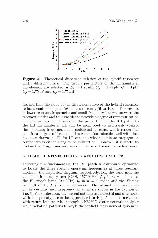
n d = βd) of the RH patchcan be assessed from the physical layout according to the classicalanalytic formulas. Fig. 4 depicts the theoretical dispersion diagramof the hybrid resonator under different electrical length of the RHpatch by combining Eqs. (3), (6) and (7). Notice that βd is evaluatedat 1.39 GHz and ZRH is preserved as 45 Ω in all cases. The circuitelements of the metamaterial TL element shown in the caption ofthe figure are arbitrarily selected without loss of generality. Followingthe figure where the resonant index is also identified, it can be easily
282 Xu, Wang, and Qi
Figure 4. Theoretical dispersion relation of the hybrid resonatorunder different cases. The circuit parameters of the metamaterialTL element are selected as Ls = 1.75 nH, Cg = 1.75 pF, C = 1 pF,Cp = 1.75 pF and Lp = 1.75 nH.
learned that the slope of the dispersion curve of the hybrid resonatorreduces continuously as βd increases from π/6 to 4π/3. This resultsin lower resonant frequencies and small frequency interval between theresonant modes and thus enables to provide a degree of miniaturizationon antenna layout. Therefore, the proportion of the RH patch tothe LH metamaterial TL can be monitored to arbitrarily controlthe operating frequencies of a multiband antenna, which renders anadditional degree of freedom. This conclusion coincides well with thathas been drawn in [27] for LP antenna whose dominant propagationcomponent is either along x- or y-direction. However, it is worth todeclare that ZRH poses very weak influence on the resonance frequency.
3. ILLUSTRATIVE RESULTS AND DISCUSSIONS
Following the fundamentals, the RH patch is cautiously optimizedto locate the three specific operating frequencies at three resonantmodes in the dispersion diagram, respectively, i.e., the band near theglobal positioning system (GPS, 1575 MHz) f−1 in n = −1 mode,the Bluetooth band (2.4 GHz) f0 in n = 0 mode and the Wimaxband (3.5 GHz) f+2 in n = +2 mode. The geometrical parametersof the designed multifrequency antenna are shown in the caption ofFig. 3. For verification, the present antenna is fabricated and assembledwith the prototype can be appreciated in Fig. 5, and is measuredwith return loss recorded through a N5230C vector network analyzerwhile radiation patterns through the far-field measurement system in

Progress In Electromagnetics Research, Vol. 137, 2013 283
(a) (b)
Figure 5. Photograph of the fabricated prototype. (a) Top andbottom view as well as (b) perspective view of the assembled antennabased on the metamaterial hybrid resonator.
(a) (b)
Figure 6. Simulated and measured return loss of the proposedantenna based on the metamaterial hybrid resonator. (a) Illustrationof the measurement; (b) comparison between simulation andmeasurement.
an anechoic chamber. Since the substrate of expected thickness isnot available in manufacture, two layers of 3 mm-thick substrate withidentical dielectric constant are bonded together to replace the thickone in the experiment. A hot press is performed to drive the airbetween the two substrates.
Figure 6 displays the simulated (characterized in HFSS) andmeasured return loss against frequency. As is appreciated, anexcellent agreement of results between simulation and measurementis unambiguously observed except for a slight frequency shift upward

284 Xu, Wang, and Qi
in the higher band in the measurement case. Moreover, both numericaland experimental results illustrate clearly three resonant modes whichcan be identified from the reflection dips. The measured return lossesare evaluated orderly as −24.6 dB, −22.4 dB and −16.58 dB at f−1 =1.52, f0 = 2.44 and f+2 = 3.57GHz, respectively, indicating perfectimpedance matching performances and an efficient design. Note thatthe n = +1 mode is not excited and the above resonant modes willbe justified and validated through both the electric field distributionanalysis and the far-filed radiation characteristics in the upcomingsection. The absolute 10 dB impedance bandwidth is measured as 40,80 and 230 MHz, corresponding to 2.63%, 3.28%, and 6.44% fractionalbandwidth, respectively. In addition to the aforementioned frequencyshift, the measured bandwidth is a little broader than that in thesimulation. These deviations can be associated with the tolerancesthat are inherent in the fabrication process. This is especially truein this particular design due to the introduced air layer between twosubstrate boards and the slight misalignment of the CSRRs and gapsin the experiment. The air layer reduces the dielectric constant, andthus degrades the quality factor and pushes up the operating frequencyaccordingly.
To further validate these resonant modes, Figs. 7 and 8 depict theHFSS-simulated electric field distribution and the three-dimensionalfar-field radiation patterns of the proposed antenna at three operatingfrequencies. It is worth pointing out the electric fields should beobserved along the 45 diagonal of the entire RH patch and CRLHsection since the antenna is diagonally excited. Following Fig. 7,very obvious uniform (in-phase) electric fields are obtained along the45 diagonal at f = 2.4GHz, implying that an infinite wavelengthis supported at this zeroth-order resonant (ZOR) mode, whereas the
(a) (b) (c)
Figure 7. Electric field distribution on the top layer of the proposedantenna based on the metamaterial hybrid resonator (a) in n = −1mode (f−1 = 1.51GHz); (b) n = 0 mode (f0 = 2.4GHz) and(c) n = +2 mode (f = 3.52GHz).

Progress In Electromagnetics Research, Vol. 137, 2013 285
(a) (b) (c)
Figure 8. Far-field radiation patterns of the proposed antenna basedon the metamaterial hybrid resonator (a) in n = −1 mode; (b) n = 0mode and (c) n = +2 mode.
electric fields at both sides of the 45 diagonal are 180 out-of-phase atthe fundamental frequency f−1 = 1.51GHz corresponding to a half-wavelength distribution. As a consequence, a patch-like radiationpattern and a monopolar radiation pattern (null radiation at thebroadside direction) are expected at 1.51 and 2.4 GHz, respectively inFig. 8. It should be noted that the field intensity in the metamaterialregion outside the microstrip patch are very weak and the phase offields still takes the half-wavelength distribution at 2.4GHz along twoprincipal axes, whereas in contrast it is uniform at the negative orderresonant mode 1.51GHz.
As to the last operating frequency around 3.5GHz, the direction ofthe fields plotted in Fig. 7(c) shifts twice along the diagonal and stilldistributes uniformly at both ends of the diagonal (one-wavelengthresonance), enabling a higher positive second order resonant moden = +2. On the other hand, the uniform field distribution alongfour patch edges implies that the n = +2 mode has been splitinto two modes with equal magnitude in two orthogonal polarization,resembling two identical antennas placed in orthogonal orientation.Since these divisive orthogonal modes do not radiate at broadside, seeFig. 8(c) due to the nonuniform aperture phase distribution, they areunable to provide a CP radiation pattern. Instead, the peak radiationpattern encounters an inclined angle around θ = −38 in xoz and yozplane, respectively and thus gives rises to the unsymmetrical quasimonopolar radiation pattern which can be further confirmed from themeasured results shown in Fig. 10. Therefore, the antenna performsspecific functions in the n = +2 mode to enable the radiating structureto be a hybrid LP antenna, which will be further illustrated later indetail.
Figure 9 depicts the HFSS simulated ARs and 2D radiationpatterns versus the elevation angle θ (Theta) at some selected specific

286 Xu, Wang, and Qi
(a) (b)
(c)
Figure 9. ARs and radiation patterns of the proposed antenna basedon the metamaterial hybrid resonator for (a) n = −1 mode; (b) n = 0mode; and n = +2 mode.
plane. Referring to the figure, one can easily find that the antennaemits a pure LP radiation pattern with AR on the order of 55 dBat f−1 = 1.51GHz, while a CP radiation with AR near 1.28 dB atf0 = 2.4GHz and a hybrid LP radiation at f+2 = 3.52GHz. The AR(evaluated at the peak radiation point) is obtained around 11.5 dB at3.52GHz, suggesting a LP radiation with imperfect polarization puritydue to the two divisive orthogonal LP modes. Remark that the antennais polarized along the ϕ = 45 diagonal in n = −1 mode, whereastwo near-degenerated orthogonal modes with 90 phase difference arealong the ϕ = 60 and ϕ = 150 plane, respectively in n = 0 mode. Incontrast, the peak radiation still occurs in the two principal plane ofϕ = 0 and ϕ = 90 in n = +2 mode. The altered LP orientation inn = −1 mode and CP orientation in n = 0 mode are attributable tothe capacitive gaps in two orthogonal directions. The currents excited

Progress In Electromagnetics Research, Vol. 137, 2013 287
(a) (b)
(c) (d)
Figure 10. Measured radiation patterns of the proposed antennabased on the metamaterial hybrid resonator for (a) n = −1 mode;(b) n = +2 mode; as well as (c), (d) n = 0 mode.
by the CSRRs flow along these gaps and make the structure functionas a monopole placed along the gap [29]. As a consequence, at leasttwo monopoles are orthogonally distributed. These aspects distinguishthe characteristics of present antenna from those of previous antennasinspired from mushroom-loaded LH TLs [18, 19].
For verification, the far-field radiation patterns are measured andplotted in two principal planes in Fig. 10. As can be evidentlyobserved, the experimental results are in excellent consistency withthe numerical ones shown in Fig. 8. A patch-like, a monopolar, and anunsymmetrical quasi monopolar radiation pattern are clearly obtainedin n = −1, n = 0 and n = +2 mode, respectively. The etchedCSRRs slots in the ground give rise to the bi-directional radiationin all resonant modes. The low cross polarization level which is morethan 30 dB lower than the co-polarization in the n = −1 mode should

288 Xu, Wang, and Qi
be highlighted, further confirming the pure LP radiation. In addition,the LH CP (LHCP, cross polarization) is also achieved almost 30 dBlower than the RH CP (RHCP, co-polarization) in n = 0 mode,indicating a fairly good CP purity, whereas a cross-polarization purityof near 13.5 dB is expected in the hybrid resonant mode n = +2.An intriguing property of the antenna should be the omindirectionalradiation (the measured power intensity fluctuates within 3 dB) in xoyplane in n = 0 mode, which would afford large service area in practice.For a comprehensive study, the effects of the ground on the antennaperformances are also numerically investigated. Plus the case of theinfinite ground, bigger and smaller ground than that in current case,total four cases are considered. For a fair comparison, the residualconditions are completely the same. Numerical results indicate that theantenna gain and cross-polarization purity are slightly improved whenthe ground extends in some specific range while are almost constantwhen the ground further increases to infinite. In either case, the otherperformances such as the fundamental working modes and the shapeof radiation patterns are almost fixed.
Figure 11 compares the simulated and measured ARs againstfrequency in the two vertical principal planes (ϕ = 60 and ϕ = 150)defined in the aforementioned section in n = 0 mode. To providea comprehensive study, the polarization states in the horizontal xoyplane are also incorporated in this figure. Following Fig. 11(a), agood agreement of results between simulation and measurement isevidenced, suggesting fairly good CP characteristics with a measured3 dB AR bandwidth (2.32–2.56 GHz) of 9.84%. From Fig. 11(b),
(a) (b)
Figure 11. Comparison of (a) the ARs between the simulation andmeasurement, and (b) the polarization states in xoy plane in n = 0mode.

Progress In Electromagnetics Research, Vol. 137, 2013 289
Table 1. Comprehensive measured behaviors of the proposed antennain different resonant modes.
Modes Center
freq.(GHz) Polarization
state S11(dB)
Rad. Effi. (%)
Antenna size ( 0)Principal
plane Bandwidth (S11/AR, %)
n=-1 LP −24.6 4.93 0.248×0.248=45o and
=135o
2.63/-
n=0 CP −22.4 2.85 0.398×0.398=60o and
=150o
3.28/9.84
n=+2 Hybrid LP −16.58 5.12 97.6 0.583×0.583=0o and
=90o 6.44/-
λ
ϕϕ
ϕϕ
ϕϕ
91.8
89.91.52
2.44
3.57
Gain (dB)
we learn that the polarization state with Gain phy and Gain thetaoccurring by turns changes every 45 of the azimuth angle. The reasonis the same due to the 2D CSRRs and gaps discussed previously. Thedetailed measured behavior of the proposed antenna is summarizedin Table 1. Note that the antenna size is characterized by theratio of the area encompassed by the top patch to the wavelengthin free space. To the authors’ best knowledge, the proposed antennaachieves one of the best performances such as the antenna gain andradiation efficiency while is with a compact prototype occupying oneof the best size reductions (75.4% smaller than conventional half-wavelength microstrip antenna evaluated at 1.52GHz) among theavailable metamaterial antennas based on mushroom structure [16–19].
4. CONCLUSION
A novel triple-band antenna based on CSRRs-loaded 2D metamaterialTL has been systematically studied in this paper. Theoretical analysisbased on Bloch theory and eigenmode analysis is also performedfor characterization and design. Both numerical and experimentalresults illustrate that the antenna operating in n = −1, n = 0,and n = +2 resonant modes exhibits a patch-like, a monopolarand an unsymmetrical quasi monopolar radiation pattern coveringthe GPS, Bluetooth, and Wimax band, respectively. Further resultsdemonstrate that the antenna provides orderly pure LP, fairly nice CPand hybrid LP radiation patterns in these three resonant modes. Theabnormal EM radiation behavior has been discussed in depth froma physical insight. The good performances of the antenna predictpromising applications in mobile and wireless local area network(WLANs) systems which require compact antennas with radiationpattern selectivity and polarization diversity.
290 Xu, Wang, and Qi
ACKNOWLEDGMENT
This work is supported by the National Natural Science Foundationof China under Grant No. 60971118, and is also supported by theInnovation Foundation for Postgraduate’s Dissertation of Air ForceEngineering University under Grant No. DY12101. The authors shoulddeliver their sincere gratitude to the anonymous reviewers for theirconstructive comments.
REFERENCES
1. Engheta, N. and R. W. Ziolkowski, Electromagnetic Metamateri-als: Physics and Engineering Explorations, Wiley, Hoboken, NJ,2006.
2. Eleftheriades, G. V. and K. G. Balmain, Negative RefractionMetamaterials: Fundamental Principles and Applications, Wiley,Hoboken, NJ, 2005.
3. Caloz, C. and T. Itoh, Electromagnetic Metamaterials: Transmis-sion Line Theory and Microwave Applications: The EngineeringApproach, Wiley, Hoboken, NJ, 2006.
4. Marques, R., F. Martin, and M. Sorolla, Metamaterialswith negative parameters: Theory, Design, and MicrowaveApplications, Wiley, Hoboken, NJ, 2008.
5. Alici, K. B., A. E. Serebryannikov, and E. Ozbay, “Radiationproperties and coupling analysis of a metamaterial based, dualpolarization, dual band, multiple split ring resonator antenna,”Journal of Electromagnetic Waves and Applications, Vol. 24,Nos. 8–9, 1183–1193, 2010.
6. Valagiannopoulos, C. A., “Electromagnetic scattering of the fieldof a metamaterial slab antenna by an arbitrarily positioned clusterof metallic cylinders,” Progress In Electromagnetics Research,Vol. 114, 51–66, 2011.
7. Du, G.-H., X. Tang, and F. Xiao, “Tri-band metamaterial-inspiredmonopole antenna with modified S-shaped resonator,” Progress InElectromagnetics Research Letters, Vol. 23, 39–48, 2011.
8. Zhao, G., Y. C. Jiao, X. Yang, C. Lin, and Y. Song, “Widebandcircularly polarized microstrip antenna using broadband quadra-ture power splitter based on metamaterial transmission line,” Mi-crow. Opt. Technol. Lett., Vol. 51, 1790–1793, 2009.
9. Bernard, L., G. Chertier, and R. Sauleau, “Wideband circularlypolarized patch antennas on reactive impedance substrates,”IEEE Antennas Wirel. Propag. Lett., Vol. 10, 1015–1018, 2011.

Progress In Electromagnetics Research, Vol. 137, 2013 291
10. Kossiavas, C., A. Zeitler, G. Clementi, C. Migliaccio, R. Staraj,and G. Kossiavas, “X-Band circularly polarized antenna gainenhancement with metamaterials,” Microw. Opt. Technol. Lett.,Vol. 53, 1911–1915, 2011.
11. Zarifi, D., H. Oraizi, and M. Soleimani, “Improved performance ofcircularly polarized antenna using semi-planar chiral metamaterialcovers,” Progress In Electromagnetics Research, Vol. 123, 337–354,2012.
12. Hosseininnejad, S. E., N. Komjani, D. Zarifi, and M. Rajabi,“Directivity enhancement of circularly polarized microstripantennas by chiral metamaterial covers,” IEICE ElectronicsExpress, Vol. 9, 117–121, 2012.
13. Zhao, G., Y. C. Jiao, F. Zhang, and X. Yang, “High gain circularlypolarized antenna using sub-wavelength resonant cavity,” Journalof Electromagnetic Waves and Applications, Vol. 24, No. 1, 33–40,2010.
14. An, J., G. M. Wang, C. X. Zhang, and H. Y. Zeng,“A compact, omni-directional, circularly polarized microstripantenna,” Microwave Journal, Vol. 53, 82-+, Jan. 2010.
15. Park, B. C. and J. H. Lee, “Omnidirectional circularly polarizedantenna utilizing zeroth-order resonance of epsilon negativetransmission line,” IEEE Trans. on Antennas and Propag.,Vol. 59, 2717–2720, 2011.
16. Park, B. C. and J. H. Lee, “Dual-band omnidirectional circularlypolarized antenna using zeroth- and first-order modes,” IEEEAntennas Wirel. Propag. Lett., Vol. 11, 407–410, 2012.
17. Herraiz-Martinez, F. J., E. Ugarte-Munoz, V. Gonzalez-Posadas,L. E. Garcia-Munoz, and D. Segovia-Vargas, “Self-diplexed patchantennas based on metamaterials for active RFID systems,” IEEETrans. on Microw. Theory and Tech., Vol. 57, 1330–1340, 2009.
18. Cao, W. Q., B. N. Zhang, T. B. Yu, A. J. Liu, S. J. Zhao,D. S. Guo, and Z. D. Song, “Single-Feed Dual-band dual-modeand dual-polarized microstrip antenna based on metamaterialstructure,” Journal of Electromagnetic Waves and Applications,Vol. 25, No. 13, 1909–1919, 2011.
19. Dong, Y. D., H. Toyao, and T. Itoh, “Compact circularly-polarized patch antenna loaded with metamaterial structures,”IEEE Trans. on Antennas and Propag., Vol. 59, 4329–4333, 2011.
20. Jung, Y. K. and B. Lee, “Dual-band circularly polarizedmicrostrip RFID reader antenna using metamaterial branch-linecoupler,” IEEE Trans. on Antennas and Propag., Vol. 60, 786–791, 2012.

292 Xu, Wang, and Qi
21. Yu, A., F. Yang, and A. Z. Elsherbeni, “A dual band circularlypolarized ring antenna based on composite right and left handedmetamaterials,” Progress In Electromagnetics Research, Vol. 78,73–81, 2008.
22. Zhang, H., Y. Q. Li, X. Chen, Y. Q. Fu, and N. C. Yuan, “Designof circular/dual-frequency linear polarization antennas based onthe anisotropic complementary split ring resonator,” IEEE Trans.on Antennas and Propag., Vol. 57, 3352–3355, 2009.
23. Dong, Y. D., H. Toyao, and T. Itoh, “Design and characterizationof miniaturized patch antennas loaded with complementary split-ring resonators,” IEEE Trans. on Antennas and Propag., Vol. 60,772–785, 2012.
24. Zhou, L., S. Liu, Y. Wei, Y. Chen, and N. Gao, “Dual-bandcircularly-polarised antenna based on complementary two turnsspiral resonator,” Electron. Lett., Vol. 46, 970–U26, 2010.
25. Jin, P. and R. W. Ziolkowski, “Multi-frequency, linear and circularpolarized, metamaterial-inspired, near-field resonant parasiticantennas,” IEEE Trans. on Antennas and Propag., Vol. 59, 1446–1459, 2011.
26. Cao, W. Q., B. N. Zhang, A. J. Liu, T. B. Yu, D. S. Guo, andK. G. Pan, “A reconfigurable microstrip antenna with radiationpattern selectivity and polarization diversity,” IEEE Antennasand Wireless Propagation Letters, Vol. 11, 453–456, 2012.
27. Herraiz-Martınez, F. J., V. Gonzalez-Posadas, L. E. Garcia-Munoz, and D. Segovia-Vargas, “Multifrequency and dual-modepatch antennas partially filled with left-handed structures,” IEEETrans. on Antennas and Propag., Vol. 56, No. 8, 2527–2539,Aug. 2008.
28. Wong, K.-L., Compact and Broadband Microstrip Antennas, JohnWiley & Sons, New York, 2002.
29. Xu, H.-X., G.-M. Wang, and J.-Q. Gong, “Compact Dual-BandZeroth-Order Resonance Antenna,” Chinese Physics Letters,Vol. 29, 014101, 2012.


![An Extremely Miniaturized Microstrip Balun Filterrepository.kmou.ac.kr/bitstream/2014.oak/8130/1/000002176475.pdf · 1957, Roberts [7] apparently reinvented the compensated balun](https://static.fdocuments.net/doc/165x107/5f7e350910136120d2269817/an-extremely-miniaturized-microstrip-balun-1957-roberts-7-apparently-reinvented.jpg)


![BRIEF PAPER Size Miniaturized Rat-Race Coupler Using Open ... · ral compact microstrip resonant cell (C-SCMRC) resonator is demonstrated in [3]. Recently, metamaterial based sub-wavelength](https://static.fdocuments.net/doc/165x107/5d038e5c88c99322638b5ff8/brief-paper-size-miniaturized-rat-race-coupler-using-open-ral-compact-microstrip.jpg)


