A miniature free piston engine/compressor - U of M ...wkdurfee/publications/engine... · A...
18
1 A miniature free-piston engine/compressor Authors: Lei Tian 1 , David B Kittelson 1 , William K Durfee 1 * Affiliations: 1 Department of Mechanical Engineering, University of Minnesota, USA. *Corresponding author. Email: [email protected] Abstract Portable powered devices such as construction tools and orthotics require a power supply that is light and compact. Hydrocarbon fuel has exceptionally high energy density compared to batteries but must be converted to mechanical power to be useful. We designed, constructed and evaluated a tiny internal combustion air compressor that uses a free-piston configuration combined with homogeneous charge compression ignition. The device compressed air in a small tank to 6.5 bar with an overall fuel to cold compressed air efficiency of 0.6%. The engine was self-regulating with the compression ratio automatically adjusting for variations in load and speed. Unlike a traditional crankshaft engine, the piston is not constrained and expansion is rapid so that combustion continues during expansion lowering efficiency. Switching from glow plug to true homogeneous charge compression ignition, which has fast kinetics will improve system efficiency as will better sealing to prevent blow-by leakage. Our mathematical model was able to predict the essential experimental results from the prototype engine. Keywords HCCI, Engine-compressor, Portable power supply, engine modeling, combustion modeling 1. Background Portable tools and wearable assistance machines require a compact, lightweight power supply. Competing technologies include batteries, fuel cells and compressed gas. However, few energy sources have the enormous energy density of hydrocarbon fuels. For example, the energy density of gasoline is about 47 MJ/kg compared to 1.8 MJ/kg for lithium polymer batteries. Thus there is motivation to develop compact power supplies that use hydrocarbon fuel as the source and produce an output that can be directly used to drive small machines. One particularly useful power output is compressed air as it is clean, has high energy density and can drive light weight air cylinders and air motors. While mains, battery and internal combustion engine powered air compressors are standard, they are either tethered or too large and too heavy for wearing. Our approach to this problem was to use homogeneous charge compression ignition (HCCI) driving a free-piston engine and combined with a compressor to produce what we believe to be the smallest internal combustion air compressor. Despite the advantages of micro-combustion for a power supply, significant technical obstacles present barriers to practical use including combustion control, quenching, exhaust gas
Transcript of A miniature free piston engine/compressor - U of M ...wkdurfee/publications/engine... · A...
1
A miniature free-piston engine/compressor
Authors: Lei Tian1, David B Kittelson
1, William K Durfee
1*
Affiliations:
1Department of Mechanical Engineering, University of Minnesota, USA.
*Corresponding author. Email: [email protected]
Abstract
Portable powered devices such as construction tools and orthotics require a power supply that is
light and compact. Hydrocarbon fuel has exceptionally high energy density compared to batteries
but must be converted to mechanical power to be useful. We designed, constructed and evaluated
a tiny internal combustion air compressor that uses a free-piston configuration combined with
homogeneous charge compression ignition. The device compressed air in a small tank to 6.5 bar
with an overall fuel to cold compressed air efficiency of 0.6%. The engine was self-regulating
with the compression ratio automatically adjusting for variations in load and speed. Unlike a
traditional crankshaft engine, the piston is not constrained and expansion is rapid so that
combustion continues during expansion lowering efficiency. Switching from glow plug to true
homogeneous charge compression ignition, which has fast kinetics will improve system
efficiency as will better sealing to prevent blow-by leakage. Our mathematical model was able to
predict the essential experimental results from the prototype engine.
Keywords
HCCI, Engine-compressor, Portable power supply, engine modeling, combustion modeling
1. Background
Portable tools and wearable assistance machines require a compact, lightweight power
supply. Competing technologies include batteries, fuel cells and compressed gas. However, few
energy sources have the enormous energy density of hydrocarbon fuels. For example, the energy
density of gasoline is about 47 MJ/kg compared to 1.8 MJ/kg for lithium polymer batteries. Thus
there is motivation to develop compact power supplies that use hydrocarbon fuel as the source
and produce an output that can be directly used to drive small machines. One particularly useful
power output is compressed air as it is clean, has high energy density and can drive light weight
air cylinders and air motors. While mains, battery and internal combustion engine powered air
compressors are standard, they are either tethered or too large and too heavy for wearing. Our
approach to this problem was to use homogeneous charge compression ignition (HCCI) driving a
free-piston engine and combined with a compressor to produce what we believe to be the
smallest internal combustion air compressor.
Despite the advantages of micro-combustion for a power supply, significant technical
obstacles present barriers to practical use including combustion control, quenching, exhaust gas
2
scavenging, thermal management, friction, sealing, starting and fabrication of small, precise parts
that operate at high temperatures. The significance of these barriers increases as the engine size
decreases because of area-to-volume and circumference-to-area scaling.
A free-piston internal combustion engine has no crankshaft. Without the kinematic
constraint of a crankshaft, the movement of the piston is driven down by pressure in the
combustion chamber and up by a rebound spring. Compared to a crankshaft engine, the free-
piston configuration is compact with fewer moving parts and no side thrust between piston and
cylinder wall. Unlike a crankshaft engine, the piston motion must be constrained for compression
ratio, ignition timing and scavenging 1. Large free-piston engine air compressors are well known
(e.g. Pescara 2, Junker
3 and Braun
4) and there has been some work at small scales (e.g. the 100
W engine by Riofrio 5 and the 500 W engine by Aerodyne Research
6.) In large free piston
engines, various control schemes are used to regulate piston motion, including controlling the
rebound energy for controlling engine compression ratio 7 and engine frequency modulation
8. In
a miniature engine design, implementing sensors and actuators is challenging, therefore our
engine was designed to run autonomously without any active control of engine speed, load,
ignition timing, fuel-air mixture or piston position.
HCCI combustion mode where the fuel-air mixture is compressed until it auto-ignites 9 is
appropriate for free-piston, micro-combustion engines. Combustion timing is a challenge in
conventional crankshaft HCCI engines but adjusts naturally in a free-piston engine as the piston
continues to compress the mixture until it auto-ignites. Ignition is nearly simultaneous within the
combustion chamber so there is no propagating flame to quench against the relatively large
surface area of a tiny engine. No spark plug or fuel injector is needed, which means tiny bore
cylinders can be realized. Finally, HCCI combustion rate is determined by chemical kinetics
rather than by flame propagation, which means a small engine can be run at exceptionally high
cycle speeds to produce reasonable power. Aichlmayr, who proposed the concept of a tiny free-
piston HCCI engine-compressor 10,11
, experimentally demonstrated that HCCI can occur in a 3
mm bore cylinder 12
, but did not create a working engine.
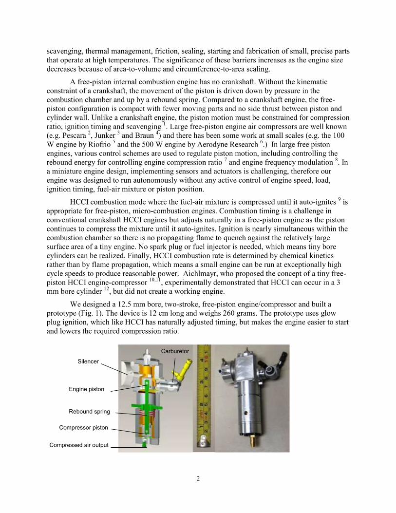
We designed a 12.5 mm bore, two-stroke, free-piston engine/compressor and built a
prototype (Fig. 1). The device is 12 cm long and weighs 260 grams. The prototype uses glow
plug ignition, which like HCCI has naturally adjusted timing, but makes the engine easier to start
and lowers the required compression ratio.
Compressor piston
Carburetor
Silencer
Rebound spring
Compressed air output
Engine piston
3
Fig. 1. Free-piston engine/compressor rendering and prototype. On the engine (upper) end, fuel air mixture induction results from the upward motion of the piston drawing the fresh mixture from the carburetor into the crankcase through a low mass reed intake check valve with Schnuerle type scavenging. Downward piston motion compresses the fresh mixture inside the crankcase, forcing it to flow around and up into the cylinder space above the piston ready for compression and combustion. On the compressor (lower) end, the reciprocating compressor piston draws in ambient air and outputs compressed air through inlet and outlet reed check valves. The downward motion of the piston is driven by the expanding combustion products inside the engine cylinder and the upward return motion is driven by the metal rebound spring and by residual compressed air below the compressor piston..
2. Engine model
2.1. Model overview
An overall mathematical model of the engine/compressor was developed based on a
previous model of a 1.5 cc glow-ignition two-stroke engine 13
with important model components
briefly described here. We experimentally tested components of the engine/compressor,
including check valve response, blow-by leakage, friction, scavenging process and combustion
process to provide parameters for the mathematical model. Because the prototype we built was
similar in size to and used several components (e.g. the piston and cylinder liner) from a 1.5 cc,
glow-ignition two stroke engine, some of the component parameter characterization was done by
testing a two stroke engine (Hornet 09 R/C Engine, AP Engines).
2.2. Piston leakage
An essential characteristic to model in miniature engines is the blow-by leakage through
the gap between engine piston and cylinder. This loss is unimportant in full scale engines but as
engine size goes down, the gap width between piston and cylinder stays approximately the same
as it is mostly determined by machining tolerances. Thus, blow-by leakage is more important in
miniature engines since the leaked mass can be a large fraction of in-cylinder charge. An orifice
flow model was used to calculate the flow rate through the piston-cylinder gap
√
where is the blow-by flow rate, is the reference intake channel area, is the flow
coefficient, subscripts 1 and 2 indicate upstream and downstream properties and subscript o
indicates stagnation parameters. The flow function for subsonic flow and sonic flow is
√
[(
)
(
)
]
(
)
√

4
where is the ratio of specific heats. The gap width was assumed to be 20 as recommended
by Sher 14
.
The leakage model was validated by motoring a 1.47 cc 2-stroke engine (Hornet 09, AP
Engines) without combustion. Figure 2 shows experimental results for peak pressure as a
function of engine speed, along with the theoretical prediction that combines heat transfer and
blow-by leakage. The data shows that both heat transfer and leakage decrease peak motoring
pressure as engine speed decreases because the engine has more time to lose heat through heat
transfer and more time to lose in-cylinder mass through leakage. The conclusion is that miniature
engines should be run at high speed to avoid excessive blow-by leakage and heat loss to improve
efficiency.
Fig. 2. Leakage model prediction of motoring peak pressure versus motoring speed, and comparison with experimental data from non-combustion engine motoring.
2.3. Piston friction
Friction has a bigger effect in miniature engines than in full scale engines because of the
larger surface to volume ratio. In addition, miniature two-stroke model engine fuel contains up to
20% lubricating oil and friction related to the resulting thick layer of lubrication oil can be
significant.
The friction level in an engine is typically described by the friction mean effective
pressure (FMEP)
For a two-stroke engine Heywood and Sher 15
recommend modeling friction as a function of
speed using a second-order polynomial
(
)
10
11
12
13
14
4000 6000 8000 10000
Mo
toring
peak
P (
bar)
Speed (rpm)
Experiments
Heat Transfer
HT+leakage
5
where FMEP is in kPa and engine speed is in rpm. In a free piston engine, however, friction
should be modeled as a function of piston speed, thus the appropriate equation is
where is friction in N, is piston speed in m/s and a, b, and c are coefficients related to
mechanical, hydrodynamic and aerodynamic friction respectively.
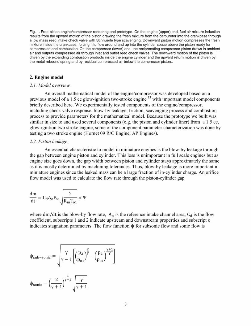
The experimental data from non-combustion motoring of the 1.5 cc 2-stroke engine were
used to parameterize the friction model. Friction was estimated from the difference between
indicated output power output and brake power and from this the mechanical efficiency was
determined. Using a least-squares fitting process, a, b and c were determined to be 1.6, 0.5 and
0.04. Modeling and experimental results are shown in Fig. 3. The mechanical efficiency of this
engine was around 70% at low speed and dropped rapidly at speeds higher than 10000 cycles per
minute.
Fig. 3. Friction mean effective pressure (FMEP) and friction power at different engine speeds.
2.4. Scavenging
The scavenging model for a two-stroke engine was used to establish the relation between
delivery ratio and charging efficiency. Delivery ratio, the ratio of charge that goes through
transfer port during scavenging to a reference mass, describes how much air-fuel mixture is used
to scavenge down the cylinder. Charging efficiency, the ratio of the retained fuel air mixture to a
reference mass, indicates how well the cylinder is refreshed with new charge after scavenging, In
a perfect-mixing scavenging model, the fresh charge mixes with exhaust completely when
scavenging. This is not desired because ideally the fresh charge should push the exhaust gases
out without mixing. In the perfect-mixing model, the relationship between delivery ratio and
charging efficiency is 16
6
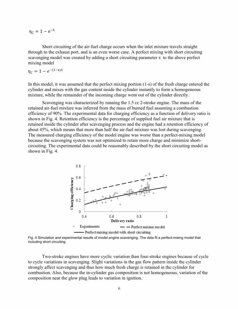
Short circuiting of the air-fuel charge occurs when the inlet mixture travels straight
through to the exhaust port, and is an even worse case. A perfect mixing with short circuiting
scavenging model was created by adding a short circuiting parameter to the above perfect
mixing model
In this model, it was assumed that the perfect mixing portion (1-s) of the fresh charge entered the
cylinder and mixes with the gas content inside the cylinder instantly to form a homogeneous
mixture, while the remainder of the incoming charge went out of the cylinder directly.
Scavenging was characterized by running the 1.5 cc 2-stroke engine. The mass of the
retained air-fuel mixture was inferred from the mass of burned fuel assuming a combustion
efficiency of 90%. The experimental data for charging efficiency as a function of delivery ratio is
shown in Fig. 4. Retention efficiency is the percentage of supplied fuel air mixture that is
retained inside the cylinder after scavenging process and the engine had a retention efficiency of
about 45%, which means that more than half the air-fuel mixture was lost during scavenging.
The measured charging efficiency of the model engine was worse than a perfect-mixing model
because the scavenging system was not optimized to retain more charge and minimize short-
circuiting. The experimental data could be reasonably described by the short circuiting model as
shown in Fig. 4.
Fig. 4 Simulation and experimental results of model engine scavenging. The data fit a perfect-mixing model that including short circuiting.
Two-stroke engines have more cyclic variation than four-stroke engines because of cycle
to cycle variations in scavenging. Slight variations in the gas flow pattern inside the cylinder
strongly affect scavenging and thus how much fresh charge is retained in the cylinder for
combustion. Also, because the in-cylinder gas composition is not homogeneous, variation of the
composition near the glow plug leads to variation in ignition.
7
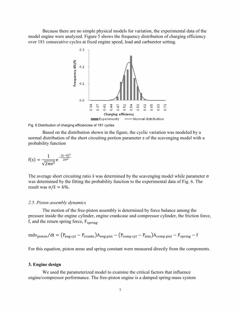
Because there are no simple physical models for variation, the experimental data of the
model engine were analyzed. Figure 5 shows the frequency distribution of charging efficiency
over 181 consecutive cycles at fixed engine speed, load and carburetor setting.
Fig. 6 Distribution of charging efficiencies of 181 cycles
Based on the distribution shown in the figure, the cyclic variation was modeled by a
normal distribution of the short circuiting portion parameter of the scavenging model with a
probability function
√
The average short circuiting ratio was determined by the scavenging model while parameter
was determined by the fitting the probability function to the experimental data of Fig. 6. The
result was .
2.5. Piston assembly dynamics
The motion of the free-piston assembly is determined by force balance among the
pressure inside the engine cylinder, engine crankcase and compressor cylinder, the friction force,
, and the return spring force, .
⁄ ( ) ( )
For this equation, piston areas and spring constant were measured directly from the components.
3. Engine design
We used the parameterized model to examine the critical factors that influence
engine/compressor performance. The free-piston engine is a damped spring-mass system
8
consisting of the rebound spring and the piston assembly. The combustion accelerates the mass
and converts expansion work to kinetic energy of the piston and potential energy of the
mechanical and compressed air springs. Friction and discharge of compressed air dissipates
energy.
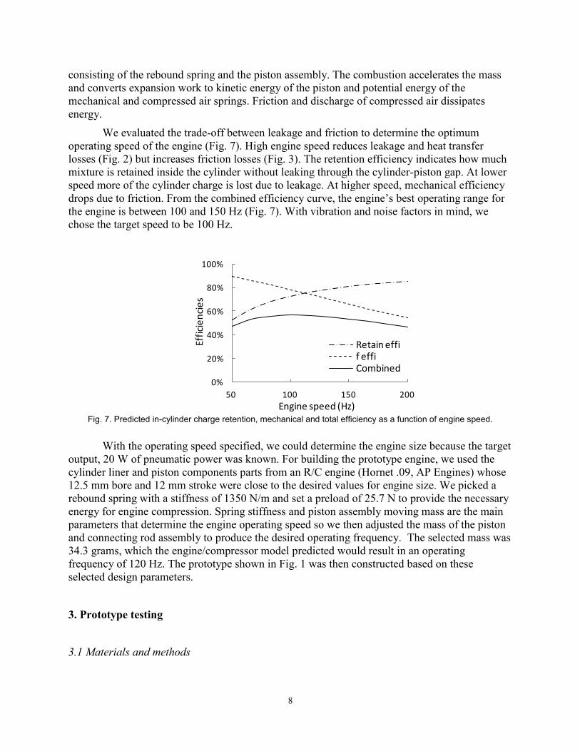
We evaluated the trade-off between leakage and friction to determine the optimum
operating speed of the engine (Fig. 7). High engine speed reduces leakage and heat transfer
losses (Fig. 2) but increases friction losses (Fig. 3). The retention efficiency indicates how much
mixture is retained inside the cylinder without leaking through the cylinder-piston gap. At lower
speed more of the cylinder charge is lost due to leakage. At higher speed, mechanical efficiency
drops due to friction. From the combined efficiency curve, the engine’s best operating range for
the engine is between 100 and 150 Hz (Fig. 7). With vibration and noise factors in mind, we
chose the target speed to be 100 Hz.
Fig. 7. Predicted in-cylinder charge retention, mechanical and total efficiency as a function of engine speed.
With the operating speed specified, we could determine the engine size because the target
output, 20 W of pneumatic power was known. For building the prototype engine, we used the
cylinder liner and piston components parts from an R/C engine (Hornet .09, AP Engines) whose
12.5 mm bore and 12 mm stroke were close to the desired values for engine size. We picked a
rebound spring with a stiffness of 1350 N/m and set a preload of 25.7 N to provide the necessary
energy for engine compression. Spring stiffness and piston assembly moving mass are the main
parameters that determine the engine operating speed so we then adjusted the mass of the piston
and connecting rod assembly to produce the desired operating frequency. The selected mass was
34.3 grams, which the engine/compressor model predicted would result in an operating
frequency of 120 Hz. The prototype shown in Fig. 1 was then constructed based on these
selected design parameters.
3. Prototype testing
3.1 Materials and methods
0%
20%
40%
60%
80%
100%
50 100 150 200
Effi
cie
nci
es
Engine speed (Hz)
Retain effif effiCombined
9
We built and tested a prototype to validate the system model and to determine overall
performance. The prototype used the cylinder liner and piston components from an AP Engines
.09 R/C engine. The remaining parts were fabricated from aluminum, steel and polymer stock.
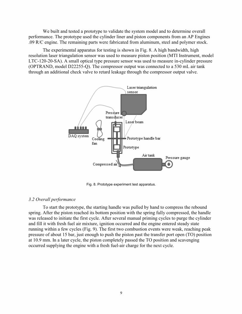
The experimental apparatus for testing is shown in Fig. 8. A high bandwidth, high
resolution laser triangulation sensor was used to measure piston position (MTI Instrument, model
LTC-120-20-SA). A small optical type pressure sensor was used to measure in-cylinder pressure
(OPTRAND, model D22255-Q). The compressor output was connected to a 530 mL air tank
through an additional check valve to retard leakage through the compressor output valve.
Fig. 8. Prototype experiment test apparatus.
3.2 Overall performance
To start the prototype, the starting handle was pulled by hand to compress the rebound
spring. After the piston reached its bottom position with the spring fully compressed, the handle
was released to initiate the first cycle. After several manual priming cycles to purge the cylinder
and fill it with fresh fuel air mixture, ignition occurred and the engine entered steady state
running within a few cycles (Fig. 9). The first two combustion events were weak, reaching peak
pressure of about 15 bar, just enough to push the piston past the transfer port open (TO) position
at 10.9 mm. In a later cycle, the piston completely passed the TO position and scavenging
occurred supplying the engine with a fresh fuel-air charge for the next cycle.
10
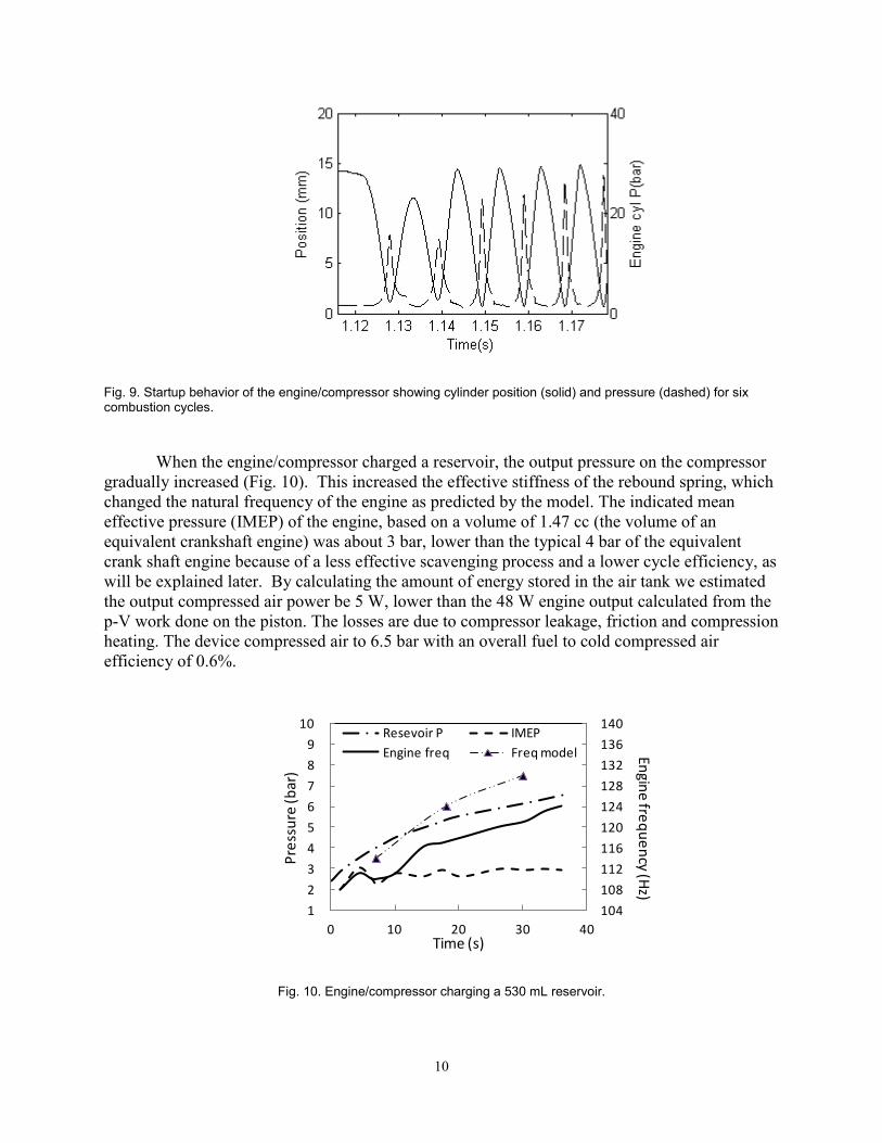
Fig. 9. Startup behavior of the engine/compressor showing cylinder position (solid) and pressure (dashed) for six combustion cycles.
When the engine/compressor charged a reservoir, the output pressure on the compressor
gradually increased (Fig. 10). This increased the effective stiffness of the rebound spring, which
changed the natural frequency of the engine as predicted by the model. The indicated mean
effective pressure (IMEP) of the engine, based on a volume of 1.47 cc (the volume of an
equivalent crankshaft engine) was about 3 bar, lower than the typical 4 bar of the equivalent
crank shaft engine because of a less effective scavenging process and a lower cycle efficiency, as
will be explained later. By calculating the amount of energy stored in the air tank we estimated
the output compressed air power be 5 W, lower than the 48 W engine output calculated from the
p-V work done on the piston. The losses are due to compressor leakage, friction and compression
heating. The device compressed air to 6.5 bar with an overall fuel to cold compressed air
efficiency of 0.6%.
Fig. 10. Engine/compressor charging a 530 mL reservoir.
104
108
112
116
120
124
128
132
136
140
1
2
3
4
5
6
7
8
9
10
0 10 20 30 40
Pre
ssu
re (b
ar)
Time (s)
Resevoir P IMEP
Engine freq Freq model Engin
e fre
qu
en
cy(H
z)

11
Unlike a crankshaft engine, the motion of the free-piston engine is dictated by the balance
of forces on each side of the piston. The model correctly predicts this motion and demonstrates
how it differs from the motion of a crankshaft engine (Fig. 11).
Fig. 11. Position-speed of the piston. Experimental data from a typical cycle of the engine/compressor running at steady state is shown along with the cycle predicted by the model. The third trace is the predicted cycle for an equivalent crankshaft engine. The vertical dashed line marks the position of a rubber limit stop bumper designed to control excessive motion during a strong combustion cycle. As the piston travels beyond (to the right of) the bumper, the kinetic energy of the moving mass is dissipated in the collision. The speed of piston at the collision point indicates how much energy is wasted in the bumper collision.
3.3 Combustion analysis
A combustion analysis was conducted using a heat release analysis method, calculating
an energy balance with the combustion chamber as the control volume. The energy balance in
the engine cylinder is
∑
where , , , , , and are mass, constant volume specific heat, temperature, heat, work,
enthalpy and internal energy, indicates the control volume, and the terms on the right side are
fuel combustion heat change, heat transfer, work output and internal energy loss due to leakage.
The temperature at each time step was calculated from measured in cylinder pressure and
Annand’s heat transfer model 17
was used to calculate heat transfer between the in cylinder
charge and the cylinder. The leakage model described above was fit to the experimental data and
used model leakage loss. The result of the combustion analysis yielded an estimate of mass
fraction burned (MFB) as a function of time during a cycle.
The heat release results for three cycles are shown in Figure 12. Ignition timing was
consistent while combustion speed varied. In most cycles combustion was slow, lasting until the
exhaust port opened, however some cycles, for example cycle 75 in the figure, had a desirable
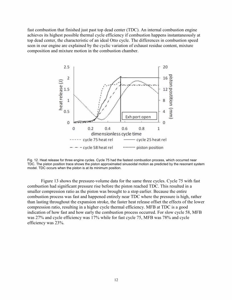
12
fast combustion that finished just past top dead center (TDC). An internal combustion engine
achieves its highest possible thermal cycle efficiency if combustion happens instantaneously at
top dead center, the characteristic of an ideal Otto cycle. The differences in combustion speed
seen in our engine are explained by the cyclic variation of exhaust residue content, mixture
composition and mixture motion in the combustion chamber.
Fig. 12. Heat release for three engine cycles. Cycle 75 had the fastest combustion process, which occurred near TDC. The piston position trace shows the piston approximated sinusoidal motion as predicted by the resonant system model. TDC occurs when the piston is at its minimum position.
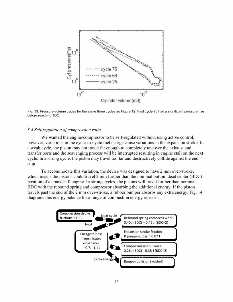
Figure 13 shows the pressure-volume data for the same three cycles. Cycle 75 with fast
combustion had significant pressure rise before the piston reached TDC. This resulted in a
smaller compression ratio as the piston was brought to a stop earlier. Because the entire
combustion process was fast and happened entirely near TDC where the pressure is high, rather
than lasting throughout the expansion stroke, the faster heat release offset the effects of the lower
compression ratio, resulting in a higher cycle thermal efficiency. MFB at TDC is a good
indication of how fast and how early the combustion process occurred. For slow cycle 58, MFB
was 27% and cycle efficiency was 17% while for fast cycle 75, MFB was 78% and cycle
efficiency was 23%.
13
Fig. 13. Pressure-volume traces for the same three cycles as Figure 12. Fast cycle 75 had a significant pressure rise before reaching TDC.
3.4 Self-regulation of compression ratio
We wanted the engine/compressor to be self-regulated without using active control,
however, variations in the cycle-to-cycle fuel charge cause variations in the expansion stroke. In
a weak cycle, the piston may not travel far enough to completely uncover the exhaust and
transfer ports and the scavenging process will be interrupted resulting in engine stall on the next
cycle. In a strong cycle, the piston may travel too far and destructively collide against the end
stop.
To accommodate this variation, the device was designed to have 2 mm over-stroke,
which means the pistons could travel 2 mm further than the nominal bottom dead center (BDC)
position of a crankshaft engine. In strong cycles, the pistons will travel further than nominal
BDC with the rebound spring and compressor absorbing the additional energy. If the piston
travels past the end of the 2 mm over-stroke, a rubber bumper absorbs any extra energy. Fig. 14
diagrams this energy balance for a range of combustion energy release..
Energy release from mixture
expansion: ~ 0.7J -1.1 J
Expansion stroke friction & pumping loss: ~0.07 J
Compressor useful work: 0.26 J (BDC) - 0.35 J (BDC+2)
Rebound spring compress work: 0.40 J (BDC) – 0.49 J (BDC+2)
Compression stroke friction: ~0.05 J
Bumper collision (wasted)Extra energy
Next cycle
Next cycle
14
Fig. 14. Energy balance for one engine/compressor cycle, running at an output pressure of 4.5 bar.
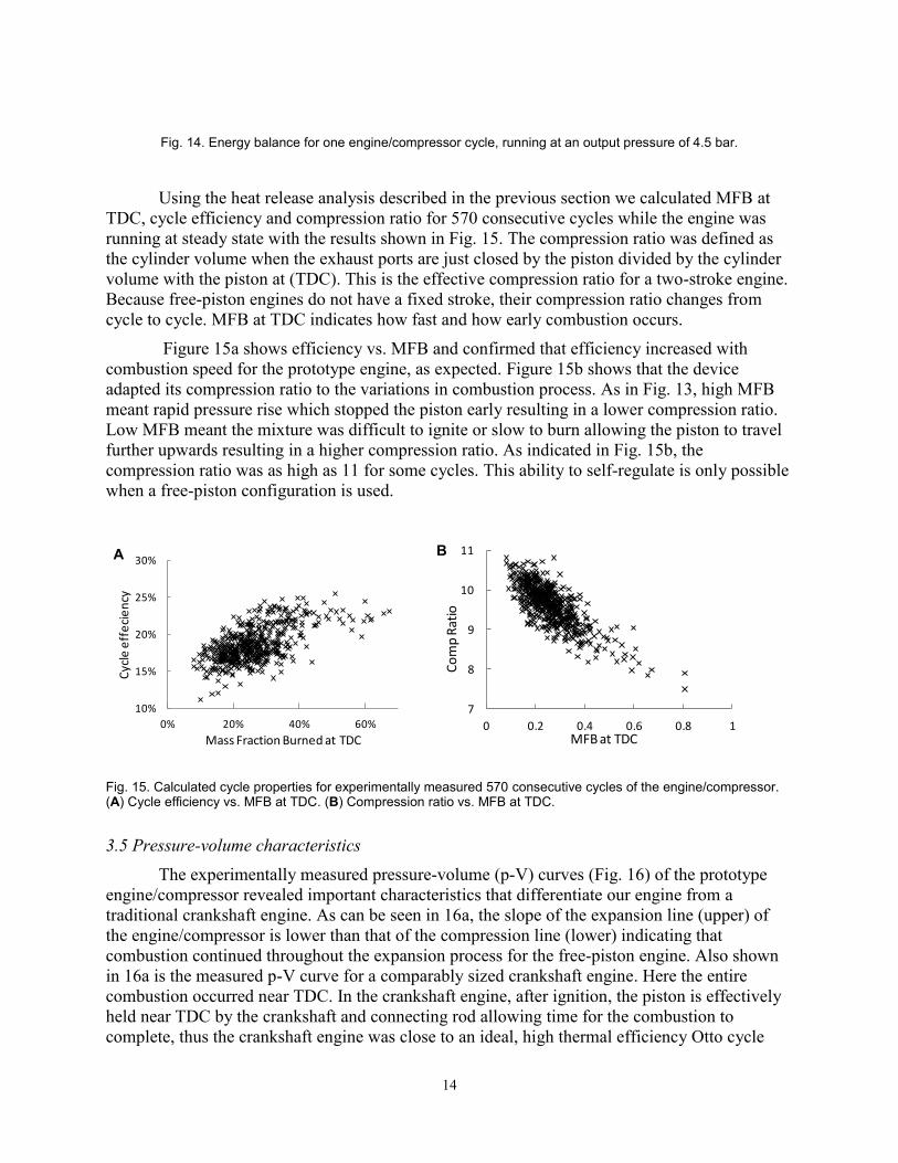
Using the heat release analysis described in the previous section we calculated MFB at
TDC, cycle efficiency and compression ratio for 570 consecutive cycles while the engine was
running at steady state with the results shown in Fig. 15. The compression ratio was defined as
the cylinder volume when the exhaust ports are just closed by the piston divided by the cylinder
volume with the piston at (TDC). This is the effective compression ratio for a two-stroke engine.
Because free-piston engines do not have a fixed stroke, their compression ratio changes from
cycle to cycle. MFB at TDC indicates how fast and how early combustion occurs.
Figure 15a shows efficiency vs. MFB and confirmed that efficiency increased with
combustion speed for the prototype engine, as expected. Figure 15b shows that the device
adapted its compression ratio to the variations in combustion process. As in Fig. 13, high MFB
meant rapid pressure rise which stopped the piston early resulting in a lower compression ratio.
Low MFB meant the mixture was difficult to ignite or slow to burn allowing the piston to travel
further upwards resulting in a higher compression ratio. As indicated in Fig. 15b, the
compression ratio was as high as 11 for some cycles. This ability to self-regulate is only possible
when a free-piston configuration is used.
Fig. 15. Calculated cycle properties for experimentally measured 570 consecutive cycles of the engine/compressor. (A) Cycle efficiency vs. MFB at TDC. (B) Compression ratio vs. MFB at TDC.
3.5 Pressure-volume characteristics
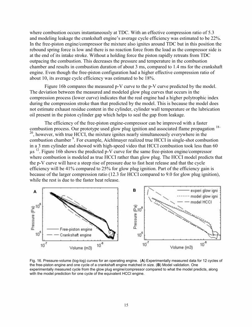
The experimentally measured pressure-volume (p-V) curves (Fig. 16) of the prototype
engine/compressor revealed important characteristics that differentiate our engine from a
traditional crankshaft engine. As can be seen in 16a, the slope of the expansion line (upper) of
the engine/compressor is lower than that of the compression line (lower) indicating that
combustion continued throughout the expansion process for the free-piston engine. Also shown
in 16a is the measured p-V curve for a comparably sized crankshaft engine. Here the entire
combustion occurred near TDC. In the crankshaft engine, after ignition, the piston is effectively
held near TDC by the crankshaft and connecting rod allowing time for the combustion to
complete, thus the crankshaft engine was close to an ideal, high thermal efficiency Otto cycle
10%
15%
20%
25%
30%
0% 20% 40% 60%
Cyc
le e
ffe
cie
ncy
Mass Fraction Burned at TDC
7
8
9
10
11
0 0.2 0.4 0.6 0.8 1
Co
mp
Rat
io
MFB at TDC
A B
15
where combustion occurs instantaneously at TDC. With an effective compression ratio of 5.3
and modeling leakage the crankshaft engine’s average cycle efficiency was estimated to be 22%.
In the free-piston engine/compressor the mixture also ignites around TDC but in this position the
rebound spring force is low and there is no reaction force from the load as the compressor side is
at the end of its intake stroke. Without a holding force the piston rapidly retreats from TDC
outpacing the combustion. This decreases the pressure and temperature in the combustion
chamber and results in combustion duration of about 3 ms, compared to 1.4 ms for the crankshaft
engine. Even though the free-piston configuration had a higher effective compression ratio of
about 10, its average cycle efficiency was estimated to be 18%.
Figure 16b compares the measured p-V curve to the p-V curve predicted by the model.
The deviation between the measured and modeled glow plug curves that occurs in the
compression process (lower curve) indicates that the real engine had a higher polytrophic index
during the compression stroke than that predicted by the model. This is because the model does
not estimate exhaust residue content in the cylinder, cylinder wall temperature or the lubrication
oil present in the piston cylinder gap which helps to seal the gap from leakage.
The efficiency of the free-piston engine-compressor can be improved with a faster
combustion process. Our prototype used glow plug ignition and associated flame propagation 18–
20, however, with true HCCI, the mixture ignites nearly simultaneously everywhere in the
combustion chamber 9. For example, Aichlmayer realized true HCCI in single-shot combustion
in a 3 mm cylinder and showed with high-speed video that HCCI combustion took less than 60
µs 12
. Figure 16b shows the predicted p-V curve for the same free-piston engine/compressor
where combustion is modeled as true HCCI rather than glow plug. The HCCI model predicts that
the p-V curve will have a steep rise of pressure due to fast heat release and that the cycle
efficiency will be 41% compared to 25% for glow plug ignition. Part of the efficiency gain is
because of the larger compression ratio (12.3 for HCCI compared to 9.0 for glow plug ignition),
while the rest is due to the faster heat release.
Fig. 16. Pressure-volume (log-log) curves for an operating engine. (A) Experimentally measured data for 12 cycles of the free-piston engine and one cycle of a crankshaft engine matched in size. (B) Model validation. One
experimentally measured cycle from the glow plug engine/compressor compared to what the model predicts, along with the model prediction for one cycle of the equivalent HCCI engine.
A B
16
4. Discussion
Our free-piston engine/compressor demonstrates that a small-scale internal combustion
air compressor is technically feasible and can attain reasonable efficiencies. Further, the
prototype engine validated the mathematical model, which means the model can be used to
optimize the device design. The prototype produced about 5 W of pneumatic output at up to 8.2
bar.
For this engine, in-cylinder mixture leakage was severe as the leakage model suggested
that at least one third of the in-cylinder charge escaped through the piston cylinder gap during
compression, combustion and expansion, resulting in significant enthalpy loss from the
combustion chamber. Thus, one of the best ways to improve the device efficiency is to design a
better lubrication and sealing system to contain the leakage.
A second important way to improve the efficiency is to switch from glow plug ignition to
true HCCI. While the model over-predicted the cycle efficiency measured in the actual engine,
the model does predict that cycle efficiency with HCCI will be significantly higher than with
glow plug ignition.
In addition to improving the overall efficiency, before the free-piston engine/compressor
can be used in a practical application, three important technical issues must be addressed. First,
a practical starting method must be devised. Second, a reliable fuel delivery system must be
designed. Third, noise and vibration must be reduced. We believe these issues are not
insurmountable and are optimistic that someday the engine/compressor can be used as a practical
portable power supply.
Acknowledgment
Supported by the Center for Compact and Efficient Fluid Power, a National Science
Foundation Engineering Research Center, funded under cooperative agreement number EEC-
0540834.
References
1. Mikalsen R, Roskilly AP. A review of free-piston engine history and applications. Applied
Thermal Engineering. 2007 Oct;27(14–15):2339–2352.
2. Pescaba EP. Motor-Compressor Apparatus. 1928 Jan 31;
3. Toutant WT. The Worthington-Junkers Free Piston Air Compressor. Journal of the
American Society for Naval Engineers. 1952;64(3):583–594.
4. Braun AT, Schweitzer PH. The Braun Linear Engine. SAE International; 1973.
5. Riofrio JA, Barth EJ. A Free Piston Compressor as a Pneumatic Mobile Robot Power
Supply: Design, Characterization and Experimental Operation. Int J Fluid Power.
2007;8(1):17–28.
17
6. Annen KD, Stickler DB, Woodroffe J. Miniature Internal Combustion Engine-Generator
for High Energy Density Portable Power. Defense Technical Information Center; 2008.
7. Huber R. Present State and Future Outlook of the Free-Piston Engine. Trans ASME.
1958;80(8):1779–1790.
8. Achten PAJ, Van Den Oever JPJ, Potma J, Vael GEM. Horsepower with Brains: The
Design of the CHIRON Free Piston Engine. SAE International; 2000.
9. Onishi S, Jo SH. Active Thermo-Atmosphere Combustion (ATAC) ---A New Combustion
Process for Internal Combustion Engines. SAE International; 1979.
10. Aichlmayr HT, Kittelson DB, Zachariah MR. Miniature free-piston homogeneous charge
compression ignition engine-compressor concept—Part I: performance estimation and
design considerations unique to small dimensions. Chem Eng Sci. 2002 Oct;57(19):4161–
4171.
11. Aichlmayr HT, Kittelson DB, Zachariah MR. Miniature free-piston homogeneous charge
compression ignition engine-compressor concept—Part II: modeling HCCI combustion in
small scales with detailed homogeneous gas phase chemical kinetics. Chem Eng Sci. 2002
Oct;57(19):4173–4186.
12. Aichlmayr HT, Kittelson DB, Zachariah MR. Micro-HCCI combustion: experimental
characterization and development of a detailed chemical kinetic model with coupled piston
motion. Combustion and Flame. 2003 Nov;135(3):227–248.
13. Tian L, Kittelson D, Durfee W. Experimental Tests and Simulations of A 1.5 cc Miniature
Glow-Ignition Two-Stroke Engine. SAE International; 2010.
14. Sher I, Levinzon-Sher D, Sher E. Miniaturization limitations of HCCI internal combustion
engines. Applied Thermal Engineering. 2009 Feb;29(2–3):400–411.
15. Heywood JB, Sher E, Engineers S of A. The Two-Stroke Cycle Engine: Its Development,
Operation, and Design. Taylor & Francis; 1999.
16. Blair GP. Design and Simulation of Two-Stroke Engines. Society of Automotive
Engineers; 1996.
17. Annand WJD. Heat Transfer in the Cylinders of Reciprocating Internal Combustion
Engines. Proc Inst Mech Eng. 1963 Jun 1;177(1):973–996.
18. Ogawa T, Kawaguchi Y. Performance Testing of 5cc Glow-Ignition Four-Stroke Engine
[Internet]. In: ASME/JSME 2007 Thermal Engineering Heat Transfer Summer Conference.
ASME; 2007 [cited 2012 Jul 5]. p. 807–814.Available from:
http://link.aip.org/link/ASMECP/v2007/i42762/p807/s1&Agg=doi
19. Raine RR, Thorwarth H. Performance and Combustion Characteristics of a Glow-Ignition
Two-Stroke Engine. SAE International; 2004.
18
20. Ma H, Kar K, Stone R, Raine R, Thorwarth H. Analysis of Combustion in a Small
Homogeneous Charge Compression Assisted Ignition Engine. Int J Engine Res. 2006 Jun
1;7(3):237–253.