A methodology for the geotechnical design of long … methodology for the geotechnical design of...
27
ITA-sponsored 2006 China International Symposium on High-Speed Railway Tunnels & Exhibition 20-21 November 2006, Beijing, China A methodology for the geotechnical design of long high-speed rail tunnels under the conditions of uncertainty Piergiorgio GRASSO, Shulin XU, Moreno PESCARA, Giordano RUSSO and Luca REPETTO Geodata S.p.A., Torino, Italy Abstract: The geotechnical design of long tunnels at great depth often has to be made under conditions of uncertainty, with stringent requirements for safety during construction and operation. Under these circumstances the geotechnical design should be developed using an innovative approach based on risk analysis and management, adopting also probabilistic techniques to perform the geotechnical characterization and the design analysis. Such an innovative approach has already been developed and applied in the recent years by the authors to many projects. In this paper the innovative approach will be described and key elements explained. The detailed procedures for applying this approach shall be illustrated using a practical example. Finally, it is also pointed out that the DESIGN of the logistics and worksites for the construction of long tunnels at great depth are as important as the geotechnical design of the tunnels themselves, and failure to recognize this point may lead to the unsuccess of the project 1. INTRODUCTION Before entering into the pure technical aspect of geotechnical design of, it is useful to examine the following general aspects: ¾ The demand for long tunnels at great depth; ¾ The main characteristics of long tunnels at great depth; and ¾ The major challenges facing the design and construction of long tunnels at great depth. 1.1 The demand for long tunnels at great depth Sustainable national and international economic developments including globalization drive for efficient mega-infrastructure projects which, in turn, demand for long tunnels at great depth. Specifically, such demands may come from various market sectors: rail and high-speed networks; motorway networks; strait crossing projects; regional, inter-region, and inter-state water/gas/oil transfer projects. High-speed railway systems represent a particular category of strategic, mega, infrastructure projects because these future life-line projects for many generations to come, often require long and deep tunnels to speed up connections by overcoming natural barriers and/or to reduce the environmental impacts by putting part of the system underground. These are particularly true for China. For example, an ambitious “Medium-long Term Railway Network Planning of China” was revealed in the ITA-China cooperation meeting held in the occasion of ITA WTC2006 in Korea (Zhao Yong, 2006). According to this plan, by 2020, the total mileage of railway lines in operation in China is expected to reach 100.000 km, with separation of passenger and goods transportation on the major, busy trunk lines, and the ratio of both the double-track and the electrification shall be increased to 50%. To reach these targets, the following will be done: ¾ Build more than 12.000 kilometres of passenger-dedicated new railway lines with target speed arriving at 200 km/h, such that a network of four vertical and four horizontal passages connecting provincial capitals and medium-large cities and three other intercity passenger-transport systems will be functional. GRASSO et al. – Paper No.2 - A methodology for the geotechnical design… 1
Transcript of A methodology for the geotechnical design of long … methodology for the geotechnical design of...

ITA-sponsored 2006 China International Symposium on High-Speed Railway Tunnels & Exhibition 20-21 November 2006, Beijing, China
A methodology for the geotechnical design of long high-speed rail tunnels under the conditions of uncertainty
Piergiorgio GRASSO, Shulin XU, Moreno PESCARA, Giordano RUSSO and Luca REPETTO
Geodata S.p.A., Torino, Italy Abstract: The geotechnical design of long tunnels at great depth often has to be made under conditions of uncertainty, with stringent requirements for safety during construction and operation. Under these circumstances the geotechnical design should be developed using an innovative approach based on risk analysis and management, adopting also probabilistic techniques to perform the geotechnical characterization and the design analysis. Such an innovative approach has already been developed and applied in the recent years by the authors to many projects. In this paper the innovative approach will be described and key elements explained. The detailed procedures for applying this approach shall be illustrated using a practical example. Finally, it is also pointed out that the DESIGN of the logistics and worksites for the construction of long tunnels at great depth are as important as the geotechnical design of the tunnels themselves, and failure to recognize this point may lead to the unsuccess of the project
1. INTRODUCTION Before entering into the pure technical aspect of geotechnical design of, it is useful to examine the following general aspects:
The demand for long tunnels at great depth;
The main characteristics of long tunnels at great depth; and
The major challenges facing the design and construction of long tunnels at great depth.
1.1 The demand for long tunnels at great depth Sustainable national and international economic developments including globalization drive for efficient mega-infrastructure projects which, in turn, demand for long tunnels at great depth. Specifically, such demands may come from various market sectors: rail and high-speed networks; motorway networks; strait crossing projects; regional, inter-region, and inter-state water/gas/oil transfer projects.
High-speed railway systems represent a particular category of strategic, mega, infrastructure projects because these future life-line projects for many generations to come, often require long and deep tunnels to speed up connections by overcoming natural barriers and/or to reduce the environmental impacts by putting part of the system underground.
These are particularly true for China. For example, an ambitious “Medium-long Term Railway Network Planning of China” was revealed in the ITA-China cooperation meeting held in the occasion of ITA WTC2006 in Korea (Zhao Yong, 2006). According to this plan, by 2020, the total mileage of railway lines in operation in China is expected to reach 100.000 km, with separation of passenger and goods transportation on the major, busy trunk lines, and the ratio of both the double-track and the electrification shall be increased to 50%. To reach these targets, the following will be done:
Build more than 12.000 kilometres of passenger-dedicated new railway lines with target speed arriving at 200 km/h, such that a network of four vertical and four horizontal passages connecting provincial capitals and medium-large cities and three other intercity passenger-transport systems will be functional.
GRASSO et al. – Paper No.2 - A methodology for the geotechnical design… 1

ITA-sponsored 2006 China International Symposium on High-Speed Railway Tunnels & Exhibition 20-21 November 2006, Beijing, China
Improve the railway network arrangement and develop new lines in the great western region of China by constructing about 16.000 kilometers of new lines.
Upgrade the existing lines and develop pivots in the railway network to augment capacity by building 13.000 kilometers of secondary lines and electrifying 16.000 kilometers existing lines.
According to the above planning, tunnels to be built in the high-speed passenger-dedicated lines will exceed 1,000 kilometres, and tunnels to be constructed in other railway lines shared by passengers and goods will be more than 2,500 kilometres. A significant number of the new tunnels on the passenger-dedicated high-speed rail lines will be long tunnels at great depth, totalling more than 400 km in length (see next sub-section for definition of long tunnels at great depth). 1.2 The main characteristics of long tunnels at great depths First of all, we refer in this paper to long tunnels at great depth as those high-speed railway tunnels whose length is usually greater 10 kilometres with the prevailing overburden thickness being more than 500 metres along the alignment.
Thus, in comparison to short tunnels at shallow depth, such long tunnels at great depth have the following main characteristics:
they take many years to plan: often 20 to 30 years, due to political, social and financial reasons and uncertainties; they need long time to construct: often 7 to 15, or even 20 years; they are complex civil engineering systems requiring not only very large-diameter tunnels
for aerodynamic reasons but also large-scale underground auxiliary structures for operational safety; the quantity of excavated materials to be disposed is huge, often millions to tens of million
cubic meters and similarly, the quantity of the required construction materials (like aggregates, cement and steel, etc.) is also great and often difficult or even impossible to be met by local sources of supply; they are commonly located in remote and high mountain areas with difficult access
conditions and very limited existing infrastructures; nevertheless, they are very often environmentally-demanding for the construction phase
(worksites, logistics of in and out, transportation and disposal of mucks); the ground conditions along the tunnel routes are complex (e.g., high variability and great
heterogeneity, active faults, presence of gases, etc.); the great overburden means and/or implies high in-situ stresses, squeezing conditions,
rock-burst conditions, presence of water under very high pressure, high ground temperatures at the tunnel elevation, etc.); finally, as for other underground construction projects, there are the time and cost
constraints which in the case of long tunnels at great depth are much more pronounced due to the scale of investment required.
Consequently, long tunnels at great depths are characterized by great uncertainties and high risks for their design and construction, because often very little is known about the geological, hydrogeological and geotechnical conditions particularly for the early stages of development. Generally speaking, the deeper the tunnel is, the larger the uncertainties involved, the higher the probability of encountering adverse or unforeseen conditions for tunnelling, and the greater the effort and the cost for doing site investigations to reduce the uncertainties.
In other words, the generally difficult natural environment (great overburden, complicated geology, harsh climate) is a source of many unforeseeable factors and thus of variations in the cost and the time required for construction, in spite of very serious studies. Typical adverse conditions or hazards (risk factors) are described by Grasso et al (2006) and Grasso & Xu (2005).
GRASSO et al. – Paper No.2 - A methodology for the geotechnical design… 2

ITA-sponsored 2006 China International Symposium on High-Speed Railway Tunnels & Exhibition 20-21 November 2006, Beijing, China It is evident that like for short tunnels at shallow depth, the first measure to reduce uncertainty and risk is to do site investigations; however, the length of the tunnel and the great depth as well as the poor access conditions all suggest that it is very difficult to do extensive site investigations.
Ideally, a preliminary risk analysis and a cost-benefit analysis should be made for designing the site investigation scheme in terms of reducing not only uncertainties in the geological, hydrogeological and geomechanical conditions, but also construction risks related to these conditions. In any case, according to the authors’ experience techniques like directional drilling of very long and deep borehole to the tunnel elevation are very much time-consuming, expensive and the conclusions are not always conclusive; furthermore, it is almost impossible to investigate the entire alignment. Alternatives can include a continuous exploratory tunnel prior to the construction of the main tunnels, or zero exploratory tunnel but systematic and continuous horizontal probing ahead (for over several hundred meters) of the excavation face. However, it should be pointed out that a continuous exploratory tunnel would face the same sort of uncertainties and risks that would otherwise be faced by the main tunnels.
On the other hand, no matter how much site investigation is carried out prior to the commencement of construction of a long-tunnel project, there will always be a degree of residual uncertainties regarding ground conditions. Even very extensive site investigations may not uncover all features of the ground to be crossed by long and deep tunnels, and unexpected conditions may always be encountered. Therefore, a certain remaining risk has to be considered, even after significant and relevant site investigations. Besides, continuity in planning and investigation should always ensure that interpretations from early phases are brought forward to the detailed design and construction phases.
1.3 The major challenges facing the design and construction First, as a conclusion of the analysis made in the sub-section 1.2 above, a common problem, also the primary challenge, is that the geotechnical design of long tunnels at great depth has to be made under conditions of uncertainty, with stringent requirements for safety during construction and operation. This geotechnical design challenge is almost always compounded by the category of political-social-financial challenges.
Indeed, in today’s rapidly changing world, the politicians and also the public are less tolerant and has no patience to wait for decades to see a strategic project implemented. Financial pressures also push for fast track solutions with quick and sure economic returns of the investment.
On the other hand, the politicians, the financiers of the project, and the public (the tax payers and also the end users) all demand for certainty of the project budget: cost and duration. For example, for the preparation of the so-called “Reference Design” for the international section of the Lyon-Turin high-speed rail project, involving two long tunnels at great depth (totalling nearly 65 kilometres), one of the major objectives set for the designers is “to estimate the costs and time for the realization of the Civil Works, giving the reliability of this estimation by specifying the associated uncertainties and degree of risk”.
However, according to Reilly (2001), chronic problems in cost estimates for underground and complex infrastructure projects have been endemic for a long time. Historically, Flyvbjerg surveyed 258 projects spanning 70 years and found that the problems with accurate cost forecasts has been chronic for that time period (NB. The findings were reported in an article by Flyvbjerg et al, 2002, with a very striking and eye-catching title – ‘Underestimating Costs in Public Works, Error or Lie?‘).
The above conflicting challenges are inter-related and clearly the link is in the uncertainty and risk involved. In fact, risk analysis and management has been a constant theme on the agenda of the ITA (International Tunnelling Associations) meetings, with guidelines, procedures and models being established for risk identification, analysis and mitigation as well as for the best practice of risk management (ITA, 2006; ITA, 2004; Grasso et al, 2002; Reilly et al, 1999).
Particularly, it should be mentioned that the Washington State Department of Transportation (WSDOT 2005), looking at a set of large, complex transportation projects, decided to develop a
GRASSO et al. – Paper No.2 - A methodology for the geotechnical design… 3

ITA-sponsored 2006 China International Symposium on High-Speed Railway Tunnels & Exhibition 20-21 November 2006, Beijing, China better cost estimation process, with John Reilly Associates International as consultant and facilitator. According to Reilly (2006), the WSDOT process has recognised that:
1) There has been a general failure to adequately recognise that an estimate of a future cost or schedule involves substantial uncertainty (risk).
2) The uncertainty must be included in the cost estimating process.
3) Costs, especially construction costs, must be validated by qualified professionals, including experienced construction personnel who understand ‘real-world’ bidding and construction.
4) Large projects often experience large-scope and schedule ‘changes’ which affect the final cost.
WSDOT developed and implemented its Cost Estimate Validation Process (CEVP). CEVP develops a probabilistic cost and schedule model to comprehensively estimate probable ranges of cost and schedule required to complete each project, like Geodata has been promoting for many years together with Prof. Einstein of MIT (Einstein et al, 1998a and 1998b; Kalamaras et al, 2000, Grasso et al, 2002, Chiriotti et al, 2003; Xu & Grasso, 2005).
2. THE KEY CONCEPT – “RANGE OF PROBABLE COST (and TIME)” In attempting to resolve the conflicting challenges discussed in the sub-section 1.3, a key concept of “Range of Probable Cost (and Time)” has been formally proposed by Reilly (2003 and 2006), see Fig. 1.
Fig. 1 Future costs are a ‘Range of Probable Costs’ (Reilly, 2006)
This key concept transmits the following messages and/or significance: In the beginning there is a large potential range for a project’s ultimate cost (and time for
realization) - depending on events that may occur; A single cost number represents only one possible result, depending on circumstances and
risk events that affect cost (and time); These circumstances and risk events are not directly controllable or absolutely quantifiable; The risk events, if they occur, produce impacts which add cost or time to the project; and Therefore, cost estimation must include both the expected (or foreseen) variation and risk
(i.e. account for uncertainty) using a logical, structured process.
To facilitate the estimation of the future costs (and time), it is necessary to analyse deeply the constituent costs (and time). For this purpose, we have made a detailed breakdown of the “probable range of costs” for the realization of the civil works, following similar analysis done by Isaksson (2002). This detailed breakdown is illustrated by the cost model shown in Fig.2.
GRASSO et al. – Paper No.2 - A methodology for the geotechnical design… 4

ITA-sponsored 2006 China International Symposium on High-Speed Railway Tunnels & Exhibition 20-21 November 2006, Beijing, China
Cost
Probability
1
Probability
2
60
0
Probability
3
0
0 50
Probability
410 20 5 15
R1 R2
2 10
R3
4 12
Rn...
5
Probability
0
= 1 + 2
Probability
0 75
6 = 3 + 5
Normal cost=f
Variance=f
Foreseen variations in theground and constructionparameters, withcorresponding designprescriptions
Base Cost=Normal Cost + Variance
Cost of each identified ResidualRisk events (1,...,n)
Summed Risk Cost=ΣRi = R1 + R2 + R3 + ... + Rn
Range of Probable Cost=Base Cost + Summed Risk Cost
100 200
Cost100 200
Cost100 200
Cost100 200
Cost200
-10 40
25
100
Normal cost
Cost
Cost Cost
Cost
DeterministicCharacterisationand Deterministic Design
Probability
ProbabilityProbability
2
50
31
6
Fig. 2 Cost Model showing the breakdown of the “Ranges of Probable Costs” of constructing a tunnels under conditions of uncertainty
GRASSO et al. – Paper No.2 - A methodology for the geotechnical design… 5

ITA-sponsored 2006 China International Symposium on High-Speed Railway Tunnels & Exhibition 20-21 November 2006, Beijing, China In producing this breakdown, it is assumed that an analysis of the Primary or Initial Risks has been made and the outcome is used to select the most appropriate construction method(s) for the tunnel in question and to devise a set of design solutions (in terms of typical sections of excavation and support), which are the two basic elements for calculating the Normal Cost.
Note that in principle, the above breakdown is also applicable to project time. However, it should be pointed out while the total project cost should be summed of all the costs corresponding to the that of the works comprising the project, the project time is determined by the longest path in the construction planning of the project.
Furthermore, it is possible to examine the Range of Probable Cost and the Range of Probable Time of a Project using a combined model as shown in Fig. 3, which is the result of simulating the combined effects of both the variability (in terms cost Variance and time Variance, see Fig.2) and the Residual Risk. Note that in the same figure it is also shown the Normal Cost and the Normal Time as a Point in the lower-left corner of the cloud or the scatter of the simulation results, to help understand better the relationship amongst the concepts introduced. Later on in the sub-section 4.4 we shall present a full combined model which reflects all the concepts of Fig. 2, in terms of both cost and time, where a summary about DAT (Decision Aids in Tunnelling) will be given.
Duration [years]5 6 7 8 9
0.40
0.45
0.50
0.55
Rela
tive
cost
0.60
Duration [years]5 6 7 8 9
0.40
Duration [years]5 6 7 8 9
0.40
0.45
0.50
0.55
Rela
tive
cost
0.60
0.45
0.50
0.55
Rela
tive
cost
0.60
+/- standard deviation
Mean of all simulations
Normal (Time, Cost)
* Result of one simulation
Probable Max Cost
Probable Min Cost
Probable Min Time
ProbableMax Time
VARIABILITY RESIDUAL RISK
Fig. 3 Example of a combined model of Cost and Time considering both Variability and Risk (a typical output of the program DAT)
With reference to the cost model shown in Fig. 2, it is clear that the key to determining a credible “range of probable costs” for a given long-tunnel-at-great-depth project lies in the correct estimation of the Variance (Item 2 in Fig. 2) and the Cost of each identified Residual Risk Event, and the solution, in turn, lies in the proper geotechnical design under conditions of uncertainty. Both experience and a correct approach are necessary to come up with the right solution.
GRASSO et al. – Paper No.2 - A methodology for the geotechnical design… 6
ITA-sponsored 2006 China International Symposium on High-Speed Railway Tunnels & Exhibition 20-21 November 2006, Beijing, China In the next sections we shall present the solution approach developed from the authors’ experience and explain the key elements of the approach, together with suggestions on the relevant operational techniques to be adopted for the resolution of each key element. 3. THE SOLUTION APPROACH The innovative approach developed by the authors to estimate a credible “range of probable cost” and a credible “range of probable time” is based on the principles of RMP (Risk Management Plan), adopting probabilistic techniques to perform the geotechnical characterization and to check the reliability of the design solutions. For the final calculation of the range of probable time and cost, the technique simulation of variations, uncertainties and risks is adopted using a specifically developed tool, code-named DAT – Decision Aids in Tunnelling.
The flowchart presented in Fig.4 shows the key elements and the logical steps of the suggested methodology.
The specific analysis techniques for some key steps shall be explained in detail later on in Section 4, while the practical procedure for applying this approach shall be illustrated in Section 5 with a example.
In the next two subsections, a quick review of the RMP principles will be done first and then some comments about each step will be given in terms of the required input data, the type of analysis involved, and any other particular aspect requiring special attention of the designer.
3.1 Review of the principles of a RMP (Risk Management Plan) As discussed in the sub-section 1.2 a long-tunnel-at-great-depth project can be associated with a series of risks and the principal risks generally derive from the uncertainties and hazards associated with the geological and construction conditions or parameters. Materialization of these risks can have a negative impacts on the project performance, with respect to time, cost, safety, and environmental aspects.
The objective of implementing a RMP for a project is to ensure that risks are reduced to acceptable levels and managed most efficiently, as illustrated in Fig. 5.
The specific type of Risk Management Plan developed by Geodata is based on the following principles:
1) Clear definitions of the basic terms to avoid misunderstanding (see also Fig. 4): Hazard is an event that may cause damage, and is associated with a probability of
occurrence, P, and impact, I, in terms of time, cost, quality, and safety. The risk, R, associated with an event is the product of the Probability of occurrence and the
Impact : R = P x I . The residual risk is defined as the risk that remains after implementation of the actions for
mitigation of the Initial (or Primary) risks. The residual risk should be evaluated for its acceptability. Analogue to the division of risks into Initial Risk and Residual Risk, hazards can also be
grouped into corresponding categories of Initial Hazard and Residual Hazard.
2) According to Grasso et al (2002), a RMP should have four essential elements: risk identification, risk quantification, risk response development, and risk response monitoring.
GRASSO et al. – Paper No.2 - A methodology for the geotechnical design… 7

ITA-sponsored 2006 China International Symposium on High-Speed Railway Tunnels & Exhibition 20-21 November 2006, Beijing, China
1. Breakdown a long tunnel into a limited number of Sections for construction
3. Analyze the Initial Risks (IRs) along the tunnel alignment
4b. Establish a set of system-wise Basic Design Solutions for the entire tunnel – Section Types
9. Assess the Residual Risks in the basic design-construction solution
R2 Probability
Impact
R3 Probability
Impact …
8. Estimate Variance (cost & time)
5. Estimate Normal Cost (and Time) - BoQ
10. Estimate the Range of Probable Cost and Time for constructing each Stretch and for constructing the whole tunnel using programs like DAT
11. Check the reasonableness of the Range of Probable Cost and Time against the corresponding Constraints imposed by the project
6b. Statistical analysis of geo- and construction-data
6a. Probabilistic characterizationof tunnel alignment
4a. Determine the system-wise best Construction Method aimed at eliminating/reducing IRs
START OF NEW PROJECT PHASE : definition of scope
END OF CURRENT PROJECT PHASE
7a. Specify range of variations in the Ground Parameters for each homogeneous zone
2. Establish the Normal (or Basic) Engineering Geological Profile and Define Reference (or Basic) Design Scenarios (deterministic characterization)
7c. Specify range of variations in the Construction Parameters
7b. Prescribe variations in the Design Elements for each Typical Section
R1 Probability
Impact
Rn Probability
Impact
Fig. 4 Flowchart showing the method for estimating a range of probable cost (and time)
GRASSO et al. – Paper No.2 - A methodology for the geotechnical design… 8

ITA-sponsored 2006 China International Symposium on High-Speed Railway Tunnels & Exhibition 20-21 November 2006, Beijing, China
Probability
Impa
ct
Initial Risk
Fig. 5 The objective of risk management
3) In apply a RMP one should keep in mind the following: No construction project is risk free. Risk can be managed, minimized, shared, transferred,
or simply accepted, but it cannot be ignored. (Managing Geotechnical Risk, C.R.I. Clayton, 2001). Realistically, not all risks associated with underground construction can be entirely avoided
or mitigated. In fact, risk management will not remove all risk from projects. For each risk, it is necessary to determine the level of acceptance. The RMP should be integrated in all phases of development of a project. The client and his project manager must recognise that certain risks will remain to be
carried by the client. This ‘residual risk’ must be allowed for in the client’s estimate of time and cost (Thompson & Perry, 1992).
3.2 Some comments for the execution of each step of the suggested methodology In this section, specific comments regarding each step of the methodology presented in Fig. 4 will be given to guide and facilitate its application.
For Step 1 (divide the tunnel into sections or stretches), the reasons for splitting a long tunnel at great depth into a reasonable of stretches for construction and the required input data and the basic analysis are given by Grasso et al. (2006, another article presented at the same symposium).
For Step 2 (establish long profile and design scenarios), the standard practice of establishing an Engineering Geological Profile for a tunnel is generally followed, and the resulting engineering geological zoning as well as the deterministic geomechanical characterization for each homogeneous zone along the tunnel shall constitute the basic input to Step 4. In addition, we have the following specific comments:
• It should be pointed out that this classic Engineering Geological Profile is only a kind of prediction of the so-called ‘Best Estimate’, which represents the conditions most likely to exist along the tunnel alignment according to the geologist who constructed this profile.
Residual Risk Impa
ct
Probability
Unacceptable
R = P × I Should be managed
Acceptable
GRASSO et al. – Paper No.2 - A methodology for the geotechnical design… 9

ITA-sponsored 2006 China International Symposium on High-Speed Railway Tunnels & Exhibition 20-21 November 2006, Beijing, China
• The degree of being a to some extent also depends on personal experience and for this reason it is normal that different geologists or geotechnical specialists may make different predictions, i.e. coming up with different profiles.
• The main disadvantage of this conventional ‘Best Estimate’ approach is that geological uncertainty is not considered explicitly. Nevertheless, it is still practised daily by many colleagues around the world.
• Another important implication of this conventional ‘Best Estimate’ approach is that also the Normal Cost calculated with reference to the profile is a prediction, representing only one of the numerous possibilities of the real world.
For Step 3 (analyse Initial Risks), it is necessary to make use of the following: • Desktop study to gather all relevant information about the tunnel corridor which could
influence the choice of the construction methods; • Collect and review critically the hard experiences gained from analogue conditions, especially
those risks actually manifested, consulting also the contractors and equipment suppliers involved;
• Site investigation data, noting that there is no good substitute for the valuable field work by experienced geologists and hydrogeologists which are also not expensive;
• Check list of risks, a very useful tool for the initial qualitative risk analysis, which can be prepared by integrating a similar list from an analogue project;
The results of the analysis of initial risks shall contribute to: the definition of the basic design scenarios, the choice of the tunnel-wise best construction method, the design of a plan of additional site investigations to reduce uncertainties, and guide the definition of the primary mitigation measures which shall be duly reflected
in the set of Basic Design Solutions to be established in Step 4b.
Risk analysis can be qualitative and quantitative, and in this relatively early step qualitative risk analysis is often used. The process of qualitative risk analysis has two aims: risk identification, and initial risk assessment. The objective is to compile a list of the main risk sources and a description of their likely consequences, perhaps including a first approximation of their potential effect on estimates of cost and time.
Three techniques can be used to make qualitative risk analysis: checklists of risk compiled from previous experience, interviews with key project participants, brain-storming with the project team.
Note that a comprehensive checklist specifically developed for long high-speed railway tunnels at great depth has been developed and it was presented recently in a workshop in China (see Xu & Grasso, 2005 for details).
For Step 4a (choose construction method): the process is an iterative one. It is necessary to first identify the feasible, alternative construction methods and then make a preliminary or conceptual design of the tunnel for each alternative method. The decision to choose the best method shall be based on:
• Knowledge of the pros and cons of the available technologies and considering also foreseeable developments in the future, through communications with the leading equipment suppliers;
• Constructability review of the Basic Design Solutions for the entire tunnel, which should be done soon after the feasible alternative construction methods have been defined for each tunnel stretch and should be done by people with great experience in similar construction works;
• Multi-criteria comprehensive comparison of feasible, alternative construction methods;
GRASSO et al. – Paper No.2 - A methodology for the geotechnical design… 10

ITA-sponsored 2006 China International Symposium on High-Speed Railway Tunnels & Exhibition 20-21 November 2006, Beijing, China
• Expert opinions and advice, whose importance can never be over-emphasized; • Make global optimization, bearing in mind that what is supposedly the best solution for a
relative small section of tunnel may need to give way to the second or even the third best solution when the small section is re-examined in the prospective of a whole tunnel stretch or the entire tunnel;
• Analysis of constraints between adjacent tunnel stretches as there may be serious interface problems which could impact significantly the production of the selected method.
For Step 4b (define Basic Design Solutions): proper design should be made for the selected construction method for the entire tunnel, ensuring that the set of Basic Design Solutions caters for all the Reference Design Scenarios.
• The solutions are usually devised based on the designer’s rich experience (or advice from experts if such experience is not available – a rare case for a client to assign the design responsibility of a long tunnel at great depth to a designer without the necessary experience).
• Then, the proposed solutions should be dimensioned through design analysis and calculations, including structural verifications.
For Step 5 (estimate the Normal Cost): a standard procedure for the preparation of bill of quantities (BoQ) can be adopted to calculate the expected Normal Cost (and Time).
• As noted before, this Normal Cost is also a prediction. • Furthermore, the Normal Cost is too high or the Normal Time is too long in comparison with
the corresponding constraints, it will be necessary return to Step 3 or even to Step1 for some particular cases to re-think about the basic design-construction solutions.
The input derived from Steps 1 to 4 for estimating the Normal Cost can be summarized using the format presented in Fig. 6.
For Step 6a (make Statistical Analyses), all available data regarding both the ground parameters and the construction variables should be treated statistically to identify the most appropriate probability distribution function of each parameter. The technique is to best-fit a probability density function to the frequency distribution of each parameter data.
For Step 6b (make Probabilistic Characterisation), the required input data can come from Step 3 and Step 6b. The analysis can be helped by using Monte Carlo simulation. This subject will be further explained in the subsection 4.1 and 4.2 later. In any case, the following should be done in this step:
• A deep re-characterization of the ground conditions along the tunnel route including re-assessment of the GEO-hazards;
• Review of the engineering geological zoning done in Step 2; • Evaluation of any extreme scenario (of crisis) and study of their impacts, in terms of
particularly the eventual need to change construction method during the phase of realization because the encountered conditions turn out to be outside the range of conditions originally foreseen for the selected construction method;
• Updating of Reference Design Scenarios; • Probabilistic prediction of the behaviour, and • Updating of risk register.
GRASSO et al. – Paper No.2 - A methodology for the geotechnical design… 11

ITA-sponsored 2006 China International Symposium on High-Speed Railway Tunnels & Exhibition 20-21 November 2006, Beijing, China
HZ-i1 HZ-i2 HZ-i3 HZ-i2 HZ-i4
Section for construction 3/n
Zone (HZ)I1 I2 I3 I2 I4RMR/GSI/Q Index
GG1@100% GG2@100% GG3@100% GG2@100% GG4@100%GG
RDS1Reference Design
A1 and A2 A2 A2 and B1 A1 and A2 C1Section type
L1 L2 L3 L4 L5
Construction Traditional (D&B) Mechanized (TBM)
Cost
Probability
C00
100%
I1GG1
I2GG2
I3GG3
I4
GSI/RMR/Q
GG4
γ1
γ2
γ3
γ4
γ
σ1
σ2
σ3
σ4
C0 ...
...
...
...
...x0
...... ... ... ...
Geomechanical parameters
Geo
mec
hani
cal
Gro
up
Deterministic value
100%
t1A1
t2A2
t3B1
t4
ReinforcedShotcrete
C1
s1
s2
s3
s4
Steel ribsspacing
Rock-boltspacing
...
...
...
...
...x0
...... ... ... ...
Primary support
Sec
tion
type
100%i1
i2
i3
i4
Note: RDS: Reference Design Scenarios (ex: squeezing, loosening, rockburst, ...) - GG: Geomechanical Group
Estimate Normal Cost (and Time) - BoQ
Section for construction 1Section for construction 2 Section for construction 3 Section for construction 4 Section for construction n
RDS2 RDS2 & RDS3 RDS2 RDS4Scenarios
Method
Homegenous
Note: γ: Unit weight - C0: Uniaxial compressive strength
Deterministic value
Tunnel
Axis Tunnel
Fig. 6 Estimate Normal Cost (and Time) For Step 7 (specify Variations in the ground, design & construction parameters), the required input data are derived from the Steps 6a and 6b as well as the specific experience of various disciplines of the design team, especially for the sub-step 7b. Note that it is implicitly assumed that in Step 7b, the set of Basic Design Solutions defined in Step 4 will be updated in the light of the updated characterization of the ground. Furthermore, the updated design solutions shall be checked again using both normal design analysis for dimensioning and structural analysis.
For Step 8 (estimate Variance), it should be noted that in practice it is not convenient to calculate directly the Variance. With reference to the Cost Model shown in Fig. 2 it is usual practice to estimate directly the Base Cost, using the same technique adopted in Step 10 for estimating the range of probable costs and time. Therefore, most of comments given under Step 10 are also
GRASSO et al. – Paper No.2 - A methodology for the geotechnical design… 12

ITA-sponsored 2006 China International Symposium on High-Speed Railway Tunnels & Exhibition 20-21 November 2006, Beijing, China applicable to Step 8. After obtaining the Base Cost, it is an easy operation to get the Variance: simply subtract the Normal Cost calculated in Step 5 from the Base Cost and the resulting distribution is the corresponding Variance.
It should be pointed out that if the Variance (of time or cost) turns out to be comparable or even higher than the Normal Cost obtained in Step 5, it shall be necessary to define and activate immediately some actions to reduce both the assumed variations in the design parameters and uncertainties. The typical action in this case is to do additional site investigations and/or to adopt design-construction solutions that are less sensitive to the variations of the ground and construction parameters.
For Step 9 (evaluate Residual Risks), the required input data can be derived from the following analyses:
• Updated design in accordance with the system-wise best solution; • Systematic identification and analysis of the residual risks remaining in the chosen design-
construction solution; • Pre-definition of counter measures and their activation mechanisms; • Expert advice.
Clearly, to systematically identify and evaluate all the risks involved in the project and to devise appropriate mitigation measures, a technical methodology or procedure should be adopted.
Thus, apart from applying again the qualitative risk analysis already adopted in Step 3, it is recommended to follow the method described by Xu & Grasso (2005) which was specifically developed for long tunnels at great depth, as mentioned previously.
Furthermore, in view of the effort made in the Steps 6 and 7, now not only it is possible but also it strongly recommended to analyse the residual risks using qualitative techniques. For example, the technique of “Reliability Analysis (ReA)” (Russo et al, 1999) can be applied to systematically check the risk of failure of the design solutions. More details on this method will be given in Section 4.3 later.
Additionally, it is important to choose the correct way of summing up the individual residual risks, i.e. the method to combine the cost of the identified residual risks (Item 4 in Fig. 2). There are two possible methods:
Method 1: to analyze any risk independently of others, with no attempt to estimate the probability of occurrence of that risk and the estimated effects of each risk is then accumulated to provide maximum and minimum project outcome values. Clearly, this is a simplified method which may exaggerate the total project risk. Method 2: although more complex, greater realism and confidence can be achieved by
applying probabilities to the risks and considering the inter-dependencies between the risks. To the authors’ knowledge, only in the program DAT (Decision Aids in Tunnelling) this method has been fully implemented with the help of probabilistic simulation, because if the number of risk events involved is large it would be very difficult and inefficient to correctly model the logic of Method 2 with a spreadsheet model as often attempted by many colleagues worldwide.
The input derived from Steps 1 to 4 for estimating the Normal Cost can be summarized using the format presented in Fig. 7.
For Step 10 (estimate the Range of Probable Costs), the required input data can be derived from the following sources: list of prices, with specific price analysis for any main items not in the list; reference prices from similar projects; longitudinal profile with engineering geological zoning and with application of the Typical
Sections (of excavation-support-lining). Note that the table below the profile should have the following distributions to allow for the estimation of the range of probable costs:
GRASSO et al. – Paper No.2 - A methodology for the geotechnical design… 13

ITA-sponsored 2006 China International Symposium on High-Speed Railway Tunnels & Exhibition 20-21 November 2006, Beijing, China
- the variation (if any) of the Geomechanical Groups in each zone and along the whole tunnel alignment;
- the variation (if any) of the Critical Scenarios in each zone and along the whole tunnel alignment.
- the distribution (discrete, in terms of type and frequency) of the identified hazards in each distinct tunnel interval along the alignment, and
- the variation (if any) of the designed solutions (Section Types) in each zone and along the whole tunnel alignment;
deterministic estimates of the quantities (i.e. traditional Bill of Quantities); for every residual hazard, the estimated impact and the probability of occurrence (NB. These
could be zone-dependent, or in other words a same hazard occurring in different zones may different probabilities and also quite different impacts.
Technically, the estimate can be done using the program DAT (see forward to the subsection 4.4 for a summary description of DAT), that is performing probabilistic simulation of the tunnel construction accounting explicitly for the foreseen possible variations in both the ground conditions and the design solutions as well as the impact of identified residual hazard, whenever possible.
Note that apart from the great advantage just mentioned under Step 9 (see above), DAT has another significant and superior characteristic: it is capable of combining the diverse opinions of different experts in the process of simulating the longitudinal engineering geological profile of a tunnel, thus overcoming one of the significant deficiencies of the conventional ‘Best Estimate’ pointed out earlier under Step 2.
For Step 11 (check reasonableness of the Range of Probable Costs and Time), first it is necessary to involve the client because the time and budget constraints or targets fixed initially by the client may need to be adjusted in the light of the final results obtained. The adjustments may be readily acceptable from the prospective of making informed and transparent decisions. On the other hand, if there is no room to adjust the targets, it is obligatory to return to Step 1 and repeat the process using alternative design and construction solutions.
GRASSO et al. – Paper No.2 - A methodology for the geotechnical design… 14

ITA-sponsored 2006 China International Symposium on High-Speed Railway Tunnels & Exhibition 20-21 November 2006, Beijing, China
Section for construction 3/n
80%GG1 & 20%GG2 80%GG2 & 20%GG1 60%GG3, 35%GG2 & 5%GG1 75%GG2 & 25%GG1 80%GG4 and 20%GG3
70%RDS1 & 30%RDS260%RDS2, 30%RDS1 &10%RDS3
50%RDS3, 40%RDS2 &10%RDS1
60%RDS2 &40%RDS1
70%RDS4, 20%RDS3 &10%RDS2
70%A1 & 30%A2 60%A2, 30%A1 & 10%B1 50%B1, 40%A2 & 10%A1 60%A2 & 40%A1 70%C1, 20%B1 & 10%A2
Δ
Δ
Δ
Δ
I1 ± ΔI1
I2 ± ΔI2
I3 ± ΔI3
I4 ± ΔI4
80%I1 & 20%I2 80%I2 & 20%I1 60%I3, 35%I2 and 5%I1 75%I2 & 25%I1 80%I4 and 20%I3
γ1 ± Δγ1
γ2 ± Δγ2
γ3 ± Δγ3
γ4 ± Δγ4
σ1 ± Δσ1
σ2 ± Δσ2
σ3 ± Δσ3
σ4 ± Δσ4
x0x0-Δx0 x0+Δx0
x0x0-Δx0 x0+Δx0
x0x0-Δx0 x0+Δx0Δx0~2⋅dev.st
L1±Δ L2±Δ L3±Δ L4±Δ L5±Δ
Triangolar
Uniform
Normal
Statistical distribution
t1 ± Δt1A1
t2 ± Δt2A2
t3 ± Δt3B1
t4 ± Δt4C1
s1 ± Δs1
s2 ± Δs2
s3 ± Δs3
s4 ± Δs4
...
...
...
...
...
...... ... ... ...
i1 ± Δi1
i2 ± Δi2
i3 ± Δi3
i4 ± Δi4
x0x0-Δx0 x0+Δx0
x0x0-Δx0 x0+Δx0
x0x0-Δx0 x0+Δx0Δx0~2⋅dev.st
Triangolar
Uniform
Normal
Probability
0Cost
-Vinf -Vsup
Traditional (D&B) Mechanized (TBM)
Note: RDS: Reference Design Scenarios (ex: squeezing, loosening, rockburst, ...) - GG: Geomechanical Group
Estimate Variance (cost & time)
Zone (HZ)RMR/GSI/Q Index
GGReference Design
Section type
ConstructionScenarios
Method
Homegenous
Δ
Δ
Δ
Δ
HZ-i1 HZ-i2 HZ-i3 HZ-i2 HZ-i4
Statistical distribution
GG1
GG2
GG3
GSI/RMR/Q
GG4
γ C0 ...
...
...
...
...
...... ... ... ...
Geomechanical parameters
Geo
mec
hani
cal
Gro
up
Note: γ: Unit weight - C0: Uniaxial compressive strength
ReinforcedShotcrete
Steel ribsspacing
Rock-boltspacing
Primary support
Sec
tion
type
Fig. 7 Estimate Variance (cost & time)
4. THE KEY ELEMENTS OF THE METHODOLOGY In this section, we shall give an overview of the specific techniques developed by Geodata to facilitate both the geotechnical design of a long tunnel at great depth and consequently the application of the methodology shown in Fig. 4 for estimating the range of probable cost and time, making reference to the example of the Lyon-Turin high-speed railway project (where relevant).
The main characteristics of the Lyon-Turin high-speed railway project are described in another article presented for the current symposium (see Grasso et al, 2006).
4.1 Probabilistic characterization of rock masses With the inherent variability in both the ground and the construction parameters and with the various uncertainties (risks) involved in an underground construction project, the classic deterministic design is becoming increasingly unacceptable. This is particularly true for long tunnels at great depth.
In view of this general situation, a probabilistic approach was developed by Geodata for the geomechanical characterization some years ago (Russo et al, 1998 and 1999), which has been updated recently (see Russo & Grasso, 2006). Aimed at fulfilling the requirements of the steps 6
GRASSO et al. – Paper No.2 - A methodology for the geotechnical design… 15

ITA-sponsored 2006 China International Symposium on High-Speed Railway Tunnels & Exhibition 20-21 November 2006, Beijing, China and 7 in Fig. 4 and establishing the necessary input data for making a probabilistic design, this approach consists in the following operations:
1) determine the most appropriate parameter to represent and quantify the rock mass structure and the most favoured choice is GSI (the Geological Strength Index defined by Hoek, 1995). This choice is based on two considerations:
the GSI is a "pure" geostructural index, and
there is a well defined set of correlations for deriving the rock mass strength and deformation properties from the value GSI;
2) do statistical analysis of the data about each elementary but key input parameter like the unconfined compressive strength of the intact rock, the RQD (rock quality designation), the spacing of the discontinuities and the conditions of the joints, and fit a probability density function to each frequency distribution of the data about elementary parameter;
3) use the Monte Carlo technique to simulate the distribution of GSI, and then
4) from the distribution of GSI derive the distributions of rock mass properties for input to probabilistic design.
The above process is depicted in Fig. 8 below.
INPUTS INPUTS DERIVED
...
...
Fig. 8 Input data for
GRASSO et al. – Paper No.2 - A methodology for the geotechnical design… 16

ITA-sponsored 2006 China International Symposium on High-Speed Railway Tunnels & Exhibition 20-21 November 2006, Beijing, China
probabilistic design
Initially, it wasn’t straightforward to simulate the distribution of GSI due to the limitations of the graphical relationship between GSI and the input parameters.
This problem has been overcome recently by adopting the alternative relationship established by Cai et al (2004). This relationship as sketched in Fig. 9 permits to calculate the value of GSI from the Block Volume (Vb) and the Joint Condition Factor (JC).
Prob
abili
ty
Forecast: GSI Frequency Chart
Frequency
Mean=50
500 Trials 500 Displayed
0.052
0.039
0.026
0.013
0.0005.97E+3 6.29E+4 1.19E+5 1.77E+5 2.34E+5
0.0
6.5
13.0
19.5
26.0
Prob
abili
ty Frequency
Forecast: Vb [cm3] Frequency Chart 500 Trials 500 Displayed
0.200
0.150
0.100
0.050
0.000
2.50E-1 1.13E+0 2.00E+0 2.88E+0 3.75E+0 0.0
25
50
75
100
Prob
abili
ty
Forecast: Jc Frequency Chart 500 Trials 500 Displayed
Frequency
31 41 51 61 70
.000
.010
.020
.030
.040
0
5
10
15
20
(*)
(**)
(*) Block Size: Massive (M); Blocky (B); Very Blocky (VB); Blocky/disturbed (B/D); Disintegrated (DS); Foliated/laminated/sheared (F/L/S).
(**) Joint or Block Wall Condition: Very Good (VG); Good (G); Fair (F); Poor (P); Very Poor (VP).
Fig. 9 Example application of the probabilistic calculation of the quantitative GSI
assessment (Russo & Grasso, 2006)
4.2 Probabilistic prediction of the ground behaviour for design For defining the typological solutions and later for dimensioning the stabilizing interventions required for the typical sections, it is important to evaluate the so-called “intrinsic behaviour” of the rock masses upon excavation, under the existing in-situ stress conditions at the design elevation of the tunnel and under the assumption of not applying any stabilization measures.
A realistic classification of the rock mass excavation-behaviour cannot be obtained without performing both the appropriate stress-deformation analysis and the geostructural analysis to identify potential failure mechanisms and modes, apart from experience.
Based on parametric analyses and observed behaviour of quite few hundred kilometres of tunnels, a behaviour classification was proposed by Geodata (see Russo et al, 1998) which recognised 6 distinct categories of behaviour (a, b, c, d, e, f) in function of the radial deformation of the excavated tunnel profile at the face and the extent of the plastic zone in the surrounding ground, with the Class “a” representing a elastic response and the Class “f” representing the condition of immediate collapse of the excavation face.
GRASSO et al. – Paper No.2 - A methodology for the geotechnical design… 17

ITA-sponsored 2006 China International Symposium on High-Speed Railway Tunnels & Exhibition 20-21 November 2006, Beijing, China On the other hand, the stress-deformation analysis by itself may not yield univocal indications about the expected deformation behaviour: for example, it is quite intuitive that a very high, unbalanced stress condition may determine either a ‘squeezing’ behaviour or a ’rock-bursting’ behaviour , depending on the structure of the rock mass. Incidentally, for the prediction of these two phenomena quite similar competence- or damage-indexes are used.
Thus, in the context of a preliminary classification of the rock mass behaviour upon excavation, it is useful to make reference also to suitable geostructural indexes especially those reflecting the self-supporting capacity of the rock mass (for example, the well know RMR system of Bieniawski and the Q-System of Barton).
In the light of the above new considerations, the basic scheme for enquiring the excavation behaviour, in terms of typical deformation phenomena has been proposed, see Fig. 10.
Stable
Caving
Squeezing
Rockburst
Instable wedges
Increasing of stress/strength ratio
Worsening of geostructural quality
Inc
reas
ing
of s
tres
s/st
reng
th ra
tio
Fig. 10. Proposed scheme for enquiring the excavation behaviour of the rock mass
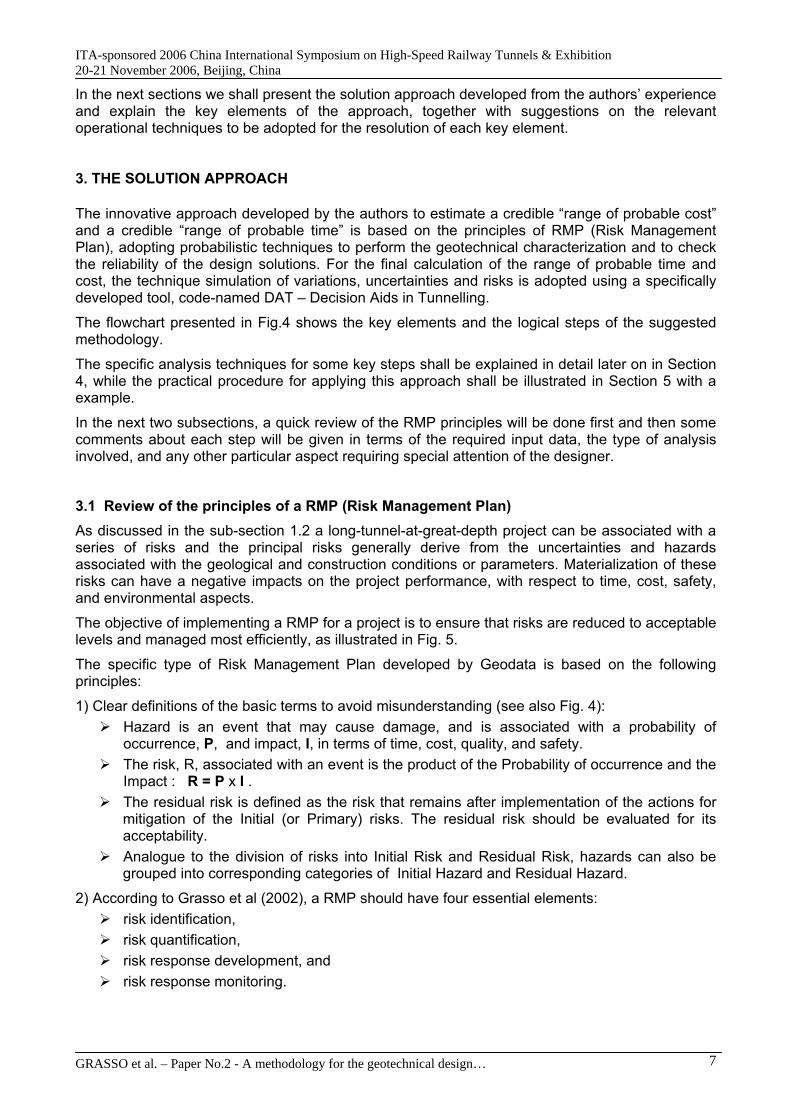
Consequently, the system of behaviour categories proposed in 1998 has been updated recently, incorporating the scheme of Fig. 10 using the RMR of Bieniawski as the bridge. This updated system, a matrix, for recognition of the behaviour of rock masses upon excavation is shown in Fig. 11.
The new matrix based on two classifications allow for the designer to focus his attention on identifying the Basic Design Scenarios, permitting a more rationalized choice of the typical stabilization measures in function of the most-probable, potential, deformation phenomenon which is otherwise associated with different combinations of stress conditions and rock mass structures.
It should be pointed out that the matrix shown in Fig. 11 is not panacea covering every possible critical situations of a project and some peculiar geological conditions. For example, the problem of swelling should be studied separately.
Nevertheless, the recent application of this matrix to the design of the long tunnels at great depths foreseen for the Lyon-Turin high speed-rail project has proven that this matrix is almost an indispensable aid to the design.
Similar to the prediction of the probabilistic distribution of GIS, the expected behaviour of the rock mass upon excavation can also be predicted in probabilistic terms, incorporating the variability and uncertainty in the geotechnical conditions of the surrounding rock mass, thanks to the new matrix
GRASSO et al. – Paper No.2 - A methodology for the geotechnical design… 18
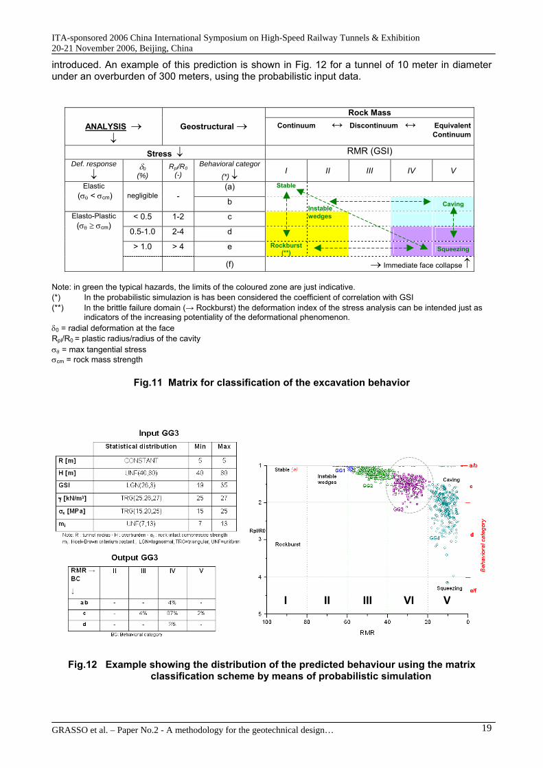
ITA-sponsored 2006 China International Symposium on High-Speed Railway Tunnels & Exhibition 20-21 November 2006, Beijing, China introduced. An example of this prediction is shown in Fig. 12 for a tunnel of 10 meter in diameter under an overburden of 300 meters, using the probabilistic input data.
Rock Mass ANALYSIS →
↓ Geostructural → Continuum ↔ Discontinuum ↔ Equivalent
Continuum
Stress ↓ RMR (GSI) Def. response
↓ δ0
(%) Rpl/R0
(-) Behavioral categor
(*) ↓ I II III IV V
(a) Stable Elastic (σθ < σcm)
negligible
-
b Caving
< 0.5 1-2 c 0.5-1.0 2-4 d > 1.0 > 4 e Rockburst
(**) Squeezing
Elasto-Plastic (σθ ≥ σcm)
(f) → Immediate face collapse ↑
Instable wedges
Note: in green the typical hazards, the limits of the coloured zone are just indicative. (*) In the probabilistic simulazion is has been considered the coefficient of correlation with GSI (**) In the brittle failure domain (→ Rockburst) the deformation index of the stress analysis can be intended just as
indicators of the increasing potentiality of the deformational phenomenon. δ0 = radial deformation at the face Rpl/R0 = plastic radius/radius of the cavity σθ = max tangential stress σcm = rock mass strength
Fig.11 Matrix for classification of the excavation behavior
I II III VI V
Fig.12 Example showing the distribution of the predicted behaviour using the matrix classification scheme by means of probabilistic simulation
GRASSO et al. – Paper No.2 - A methodology for the geotechnical design… 19

ITA-sponsored 2006 China International Symposium on High-Speed Railway Tunnels & Exhibition 20-21 November 2006, Beijing, China 4.3 Probabilistic Design and Design Verifications Already mentioned many times in this article the geotechnical design of long tunnels at great depth is dominated by the inherent variability and uncertainty (risk) in the ground conditions. As shown in the above subsections, it is possible to use probabilistic techniques to establish a more rational and comprehensive picture for the design.
The next design step (see also Step 7 of Fig. 4) is to prescribe the design solutions with appropriate variations in the support elements to cope with the variability and uncertainty and the total number of solutions and the corresponding prescribed variations have to be limited in order to be practically manageable during construction. However, this is not an easy task, because on the one hand, one cannot prescribe extremely conservative solutions so as to cover the extreme, worst possible scenarios, for example by using always the minimum geomechanical properties and on the other hand, there is also the risk of having a typical section with inadequate support to cover the low range of the geomechanical conditions in a given homogeneous zone. The former will, no doubt, produce uneconomic designs while the latter will lead to local failures of the tunnel as sometime happens. With the conventional deterministic design approach, this conflict is practically neglected.
Therefore, to arrive at a set of economical and reliable typical sections (or design and construction solutions), it requires not only experience of the designer but also a tool help the designer to check his prescribed solutions.
The above challenge prompted Geodata engineers to research for a method to advance the state of the art and to give added value to each project by producing balanced design solutions with manageable minimum residual risks. The solution has been found and it is the integration of the cited “ReA" method in the Risk Management Plan for a given project.
It is worth of pointing out that for long tunnels at great depth the shape of the tunnel is generally circular or quasi-circular even for those stretches excavated by conventional methods, and in-situ stress field tends to be homogeneous with Ko=1 or close to unity. These characteristics offer the possibility to use analytical, closed-form solutions for the tunnel design, with for example the convergence confinement method. This simplification, in turn, facilitates the implementation of efficient, parametric and probabilistic analysis, which is needed for systematic check of the reliability of the design solutions prescribed by the designer.
Here we shall give only a synthesis of the "ReA" approach and interested readers should refer to the original article for more details.
The essence of checking the reliability of the a typical section with prescribed variations in the quantities the various support elements is to quantify the probability of instability or failure of this support system in the context of the foreseen geomechnical conditions with probabilistically quantified variability in the parameters.
The reliability is expressed in terms of a so-called ‘Safety Margin (S)’, which is equal to the difference between the support system Capacity (C) and the support Demanded (D) by the foreseen ground conditions with variability. Mathematically, S = C – D, with both C and D being evaluated probabilistically to account explicitly for the foreseen variabilites.
The procedure for estimating the reliability of a support system for a given tunnel zone is illustrated in Fig. 13.
GRASSO et al. – Paper No.2 - A methodology for the geotechnical design… 20

ITA-sponsored 2006 China International Symposium on High-Speed Railway Tunnels & Exhibition 20-21 November 2006, Beijing, China
GRASSO et al. – Paper No.2 - A methodology for the geotechnical design… 21
Fig. 13 Flowchart showing procedure for estimating the reliability of a support system for a
given tunnel zone
DEFORMATION, u so, ATDISTANCE d FROM
THE FACE
GSIRES/GSI FACTOR
% OF PLASTIC ZONE WEIGHT
NUMBER OF SIMULATIONS
Plastic zone thicknessat equilibrium [r p.eq]
Behavioralcategories
c
d eCapacity [C] &
demand [D]
Safety margin, [S]
Distribution of behavioral categories Basic statistics, μ and σ , of capacity [C], demand [D], plastic zone thickness at equilibrium [rp.eq], safety margin [S, S=C-D] distributionsProbability of failure, Pf Reliability index, β
END
START
SUPPORTSYSTEM DATA
GEOMECHANICALDATA
Generation of randomnumbers for the inputdistributions using thelatin hypercube sampling scheme andrank correlation.
DEFINITION OF P ireq USING THE BISECTION METHOD
Pi [
MP
a]
Deformation [m]
Pireq, Demand [D]Capacity
[C]
Tolerance: E-5MPa Max.no iterations: 500
uso
according toRusso et al.1998, 2006
Convergence-Confinement Solution of Carranza T. (2003-2004)
Calculation of the stiffness and capacity of the support according to Hoek and Brown (1980) and Carranza T. (2003-2004)

ITA-sponsored 2006 China International Symposium on High-Speed Railway Tunnels & Exhibition 20-21 November 2006, Beijing, China The procedure to estimate the reliability of the primary support system is illustrated with an example application with reference to the Lyon-Turin high-speed rail project, for comparison and optimization among different design solutions in terms of the support type elements and the intensity of intervention. In particular, two typological sections, S2 and S4, are compared in Fig. 14. where it is also given indications about the principal characteristics and the geometry of the two sections under comparison. The reliability of the support system is estimated considering an overburden class of H=1000÷1500m and a rock mass with GSI=60-70, for both section types.
-0.10 -0.05 0.00 0.05 0.10 0.15 0.200
20
40
60
80
100
(S2) (S4)
Pf≅14%
(S2) SF=1.20 β=0.78
Prob
abili
ty [%
]
Pf≅1%β=2.70
(S4)SF=1.60
~14%
~1%
Safety Margin
a) Cumulative probability distribution of safety margin for two possible primary support systems
Shotcrete (s): ts=15±5cm Rockbolt (b): ib=2.0±0.5m
Shotcrete (s): ts=25±5cm Steel Ribs (r): ir=1.25±0.25m
(S2)
(S4)
b
s s+r
ib±Δib
ir±Δir
b) Geometry and support characteristics
Fig. 14 Example application of the procedure shown in Fig. 13 to compare the reliability of
two possible primary support systems for a given situation As it is shown in Figure 14, the analysis revealed that the solution (S2) is associated with an unacceptable probability of failure, Pf (14%), despite that the SF value is equal to approximately 1.2. The cumulative, safety margin distribution for the alternative solution (S4), consisting of steel ribs and shotcrete, has only a Pf of less than 1%. This solution S4 is to be preferred since, apart from its design superiority, it is also associated with favourable cost and advance rate indices.
GRASSO et al. – Paper No.2 - A methodology for the geotechnical design… 22

ITA-sponsored 2006 China International Symposium on High-Speed Railway Tunnels & Exhibition 20-21 November 2006, Beijing, China 4.4 Summary of DAT The system DAT (Decision Aids in Tunnelling) is a tool for making probabilistic estimates of the range of probable time and cost of constructing a tunnel, or a network of tunnels, taking into account the variability and uncertainty (risk) in the geologic and construction variables.
A DAT run is essentially a computer simulation of several random processes. The idea of using computer simulations comes with the fact it is not possible to find analytically resulting random functions when processes are too complicated like the construction of tunnels under uncertainty. So simulating a construction process is the only solution to obtain statistical information about the total time and cost. This information gives a good idea on the average, minimum and maximum expected values. By definition the simulation of a random process uses a random number generator.
DAT and the associated computer code SIMSUPER have been developed over a period of 20 years by MIT (Massachusetts Institute of Technology) and EPFL (École Polytéchnique Fédérale de Lausanne), with the participation of the US National Science Foundation, the Swiss Federal Office for Transportation, the Swiss Science Foundation, and Geodata S.p.A.
A unique feature of DAT is its capability for a comparative evaluation of the performance of project alternatives (different construction schemes, in terms of alignment and methods of construction), with respect to the potential of these alternatives in managing geotechnical and construction uncertainties within prescribed, or acceptable values of time and cost.
SIMSUPER has two interrelated simulation modules: Geology and Construction.
In the Geology module the geotechnical conditions are organized in the various input matrices following an approach similar to that of defining a geotechnical profile, i.e., defining, chainage by chainage, all the geological and geomechanical conditions that have an impact on the tunnel construction. The user’s (designer’s) task is to identify and define which are those parameters and what are their possible states. Uncertainty in this definition is either entered by indicating the variability in the assigned value of the parameter, and/or in its state probability. In addition, variability of conditions along a tunnel segment (or a so-called ‘homogeneous zone’) is modelled using a Markov process. In a manner similar to defining the geomechanics classification, different parameter states are combined to define homogeneous ground classes that are subsequently associated with the construction methods. For example, if problematic water inflows and squeezing conditions are identified as impacting parameters, their possible states have to be defined, as well as the influence of their possible state combinations on every excavation phase modelled in the subsequent construction module.
The Construction module consists of two principal components:
The first refers to the construction methods where the construction cycle can be simulated activity by activity. In this case, variability is introduced into the model by statistical distributions of basic construction indices, e.g., advance rate and unit cost, usually derived practical case histories and price analysis.
The second module, which is referred to as tunnel network, permits the definition of the sequence of realization of a tunnel section and a project, e.g., two opposite fronts for a tunnel, or excavation of a pilot bore by a TBM, followed by the enlargement by conventional methods.
In both the geology and the construction modules, variability of the parameters is described through a user-defined distribution function that can be chosen from among Uniform, Triangular, and Bounded Triangular distributions. In the Uniform distribution the variable always has the same probability of taking on any value. In the Triangular distribution a minimum value, a most likely value (the mode), and a maximum value have to be provided, recognizing that the total area under the triangle must equal one (as the total probability of occurrence of the parameter must be 100%). In the Bounded Triangular distribution, the probabilities on the minimum and maximum boundaries of the triangle are greater than zero.
GRASSO et al. – Paper No.2 - A methodology for the geotechnical design… 23

ITA-sponsored 2006 China International Symposium on High-Speed Railway Tunnels & Exhibition 20-21 November 2006, Beijing, China Some advantages of the DAT system have already been pointed out earlier in the subsection 3.2. More details about how DAT works and how DAT can be used to compare alternative design-construction solutions for a given project can be found in the publications of Einstein et al (1998a and 1998b).
In Fig. 15 it is presented the final results obtained from a complete DAT analysis made for the Lyon-Turin high-speed rail project involving two long tunnels. The simulation is based on the recently completed Reference Design (see Grasso et al, 2006, for the definition of this reference design). In Fig. 15, the results are presented in the easy-to-understand format shown previously in Fig. 3, with comparison of two scenarios: with –vs- without the identified residual risks.
Fig. 15 The combined model of Cost and Time for the Reference Design of the LTF project Finally, it should be pointed out that the realism of estimates increases as a project proceeds, but, of course, the most influential decisions are made early in the life of projects. So, despite the difficulties, a realistic estimate of the final cost and duration of the total project is required as early as possible. Such is the case for the LTF project as mentioned in Grasso et al (2006): DAT
GRASSO et al. – Paper No.2 - A methodology for the geotechnical design… 24

ITA-sponsored 2006 China International Symposium on High-Speed Railway Tunnels & Exhibition 20-21 November 2006, Beijing, China analyses have been made initially for the feasibility study in 2000, and then for the preliminary design in 2004 and now for the Reference Design in 2006.
There is a second, equally important, reason for the early identification of risk and uncertainty and apply DAT to simulate them in the construction process: it should focus the attention of project owner’s management on the need for strategies for the control and allocation of risk, for example through the choice of a contract strategy. It will also make obvious what further design, development work or other actions, such as clarifying objectives, is most needed.
4.5 Other critical aspects for the successful Apart from making a good geotechnical design using the advanced techniques presented in this article and applying the recommended methodology to establish a realistic combined Cost-Time model for the project with explicit modelling of variability and risks, it is also necessary to develop the following aspects as the integral part of the geotechnical design:
Definition of counter measures for managing the residual risks with clear mechanisms for the activation of these pre-designed counter measures, including a robust geotechnical monitoring program as well as a practical procedure for real-time analysis of all data collected.
Earlier involvement of the technology suppliers, especially TBM manufacturers if mechanized solutions are select for the long tunnel in question.
Prepare specific technical and construction specifications compatible with the identified variability and uncertainty, for example applying the well-know approach of “Geotechical Baseline Report” with due recognition of the foreseen and foreseeable variability and risks.
The design of the logistics and worksites for the construction of a long tunnel at great depth is as important as the geotechnical design of the tunnel itself.
Finally, the designer should also contribute to the definition and choice of a most suitable contract strategy for the project, with appropriate residual risk-sharing mechanisms based on the results of the simulations using the combined Cost-Time model that promotes cooperation of the parties involved, creating thus a fair and win-win situations.
5. CONCLUSIONS Long tunnels at great depths have to be designed and constructed under the conditions of
uncertainty and one of the keys to success is, according to the authors’s experience through implementation of a properly designed Risk Management Plan (RMP).
In this paper we have presented an innovative methodology, driven by the principles of RMP, for estimating the Range of Probable Cost (also Time) for a long tunnel at great depth project, catering explicitly for the variability and uncertainty (risk), with reference to the cost-breakdown model shown in Fig. 2. The methodology was developed from Geodata’s long experience and has been constantly refined through to application to challenging underground construction projects.
An overview of the series of innovative probabilistic techniques developed by Geodata to facilitate the application of the innovative methodology is given in Section 4. These techniques have become increasingly indispensable for making a sound and robust geotechnical design for any underground construction projects, especially those complex and or mega projects like long high speed railway tunnels.
Finally, it should be pointed out that the principles and the methodology presented in this paper is clearly also applicable to other long tunnels at great depth, for example, very long tunnels for motorways and for transferring great quantities of water.
GRASSO et al. – Paper No.2 - A methodology for the geotechnical design… 25

ITA-sponsored 2006 China International Symposium on High-Speed Railway Tunnels & Exhibition 20-21 November 2006, Beijing, China 6. REFERENCES Cai M., Kaiser P.K., Uno H., Tasaka Y. and Minami M. (2004). Estimation of Rock Mass Deformation Modulus and Strength of Jointed Hard Rock Masses using the GSI system. International Journal of Rock Mechanics and Mining Sciences n.41, pp.3-19.
Carranza-Torres C. (2003). Computation of stress and displacement distributions around circular opening subject to symmetrical loading in elasto-plastic Mohr-Coulomb and Hoek-Brown materials. Personal communication, submitted to E.Hoek and B.Corkum (Rocscience).
Carranza-Torres C. (2004). Elasto-plastic solution of tunnel problems using the generalized form of the Hoek–Brown failure criterion. Proceedings of the ISRM SINOROCK 2004 symposium China, May 2004. Edited by J.A. Hudson and F. Xia-Ting. Volume 41, Issue 3, Pages 480-481.
Chiriotti E., Grasso P. & Xu S. (2003). Analysis of tunnelling risks: state-of-the-art and examples. Gallerie e Grandi Opere Sotterranee, n.69 – aprile 2003 (in both Italian and English), pp.35-44. Clayton C.R.I. (2001). Managing Geotechnical Risk. Improving Productivity in UK Building and Construction. Institution of Civil Engineers, London. Thomas Telford Publishing, London.
Einstein H.H., Xu S., Grasso P. & Mahtab A.. (1998a). Decision aids in tunnelling. World Tunnelling, April 1998. pp. 157-159.
Flyvbjerg, B; Holm, MS, Buhl, S (2002). Underestimating Costs in Public Works, Error or Lie? American Planning Association Journal, Summer 2002.
Einstein H.H., Indermitte C.A., Descoeudres D., Grasso P., Mahtab M.A. & Xu S. (1998b). Creating the basis for risk assessment in tunnelling - The decision aids for tunnelling (DAT). Proceedings of the Conference on Reducing Risk in Tunnel Design and Construction, Basel, Switzerland, 7-8/12/1998.
Grasso, P, Mahtab, M, Kalamaras, G & Einstein, H H (2002), ‘On the Development of a Risk Management Plan for Tunnelling’, Proc. AITES-ITA Downunder 2002, World Tunnel Congress, Sydney, March.
Grasso P., Xu S., Carrieri G., Guglielmetti V. & Rizzo F. (2006). On the choice of optimal method for the excavation of long high-speed rail tunnels at great depth. Proceedings of China International Symposium on High-Speed Railway Tunnels & Exhibition, 20-21 November 2006, Beijing, China.
Hoek E. and Brown E. T. (1980). Underground Excavations in Rock. The Institute of Mining and Metallurgy, London.
Hoek E., Kaiser P.K. and Bawden W.F. (1995). Support of Underground Excavations in Hard Rock. Balkema, Rotterdam, 215pp.
Isaksson T., (2002). Model for estimation of time and cost, based on risk evaluation applied to tunnel projects. Doctoral Thesis, Division of Soil and Rock Mechanics, Royal Institute of Technology, Stockholm.
ITA 2004. Guidelines for Tunnelling Risk Management. International Tunnelling Association, Working Group 2, TUST Vol 19, No. 3, pp217-237.
ITA 2006. Open Session of WTC2006 on Risk Management of Tunnel Projects. http://www.ita-aites.org/cms/1576.html
Kalamaras G.S., Brino L., Carrieri G., Pline C. & Grasso P. (2000). Application of multicriteria analysis to select the best highway alignment. Tunnelling and Underground Space technology, Vol. 15, No. 4, pp. 415-420.
Reilly J.J. (1999), Isaksson T. & Anderson J. (1999). Tunnel Procurement-Management Issues and Risk Mitigation. Proc. 10 th Australian Tunneling Conference, Melbourne, March.
Reilly J.J. (2001). Managing the Costs of Complex, Underground and Infrastructure Projects. American Underground Construction Conference, Regional Conference, Seattle, March 2001.
Reilly J.J. (2003). Towards Reliable Cost Estimates. Tunnels & Tunneling, North American Edition, September, Viewpoint Article, p4.
Reilly J.J. (2006). Calculating the risks. Tunnelling and Trenchless Construction, April 2006, pp. 43-44.
Russo G., Kalamaras G.S. and Grasso P. (1998). A discussion on the concepts of geomechanical classes, behavior categories and technical classes for an underground project. Gallerie e grandi opere sotterranee, N.54, pp.40-51.
GRASSO et al. – Paper No.2 - A methodology for the geotechnical design… 26
ITA-sponsored 2006 China International Symposium on High-Speed Railway Tunnels & Exhibition 20-21 November 2006, Beijing, China Russo G., Kalamaras G., Xu S. and Grasso P. (1999). Reliability analysis of tunnel-support systems. Proceedings of the 9th International Congress of Rock Mechanics. Paris, 25-28/08/1999.
Russo G. and Grasso P. (2006). Un aggiornamento sul tema della classificazione geomeccanica e della previsione del comportamento allo scavo. Gallerie e grandi opere sotterranee, n.80.
Thompson & Perry, Engineering construction risks , 1992.
WSDOT 2005, Cost-Risk Assessment Website: ww.wsdot.wa.gov/projects/projectmgmt/riskassessment
Xu S. and Grasso P. (2005). Risk Analysis of Mega Tunnelling Projects (in Chinese). Proceedings of China National Symposium on Key Problems and TBM Application in the West Line of the Mega South to North Water Diversion Project, September 12-14 2005, Beijing, China.
Zhao Yong from Center for Project Design Appraisal, the Ministry of Railways, China. Introduction to Mid-long Term Railway Network Planning of China, presented at the ITA-China meeting held in the occasion of ITA WTC 2006, Soul, Korea.
GRASSO et al. – Paper No.2 - A methodology for the geotechnical design… 27