A mass constraint formulation for structural topology optimization with multiphase materials
23
INTERNATIONAL JOURNAL FOR NUMERICAL METHODS IN ENGINEERING Int. J. Numer. Meth. Engng 2011; 88:774–796 Published online 1 May 2011 in Wiley Online Library (wileyonlinelibrary.com). DOI: 10.1002/nme.3197 A mass constraint formulation for structural topology optimization with multiphase materials Tong Gao 1,2 and Weihong Zhang 1, ∗, † 1 Sino-Belgian Laboratory of Aerospace Computing, The Key Laboratory of Contemporary Design and Integrated Manufacturing Technology, Northwestern Polytechnical University, 710072 Xi’an, People’s Republic of China 2 LTAS—Ingénierie des Véhicules Terrestres, Université de Liège, 4000 Liège, Belgium SUMMARY This work is focused on the topology optimization of lightweight structures consisting of multiphase materials. Instead of adopting the common idea of using volume constraint, a new problem formulation with mass constraint is proposed. Meanwhile, recursive multiphase materials interpolation (RMMI) and uniform multiphase materials interpolation (UMMI) schemes are discussed and compared based on numerical tests and theoretical analysis. It is indicated that the nonlinearity of the mass constraint introduced by RMMI brings numerical difficulties to attain the global optimum of the optimization problem. On the contrary, the UMMI-2 scheme makes it possible to formulate the mass constraint in a linear form with separable design variables. One such formulation favors very much the problem resolution by means of mathematical programming approaches, especially the convex programming methods. Moreover, numerical analysis indicates that fully uniform initial weighting is beneficial to seek the global optimum when UMMI-2 scheme is used. Besides, the relationship between the volume constraint and mass constraint is theoretically revealed. The filtering technique is adapted to avoid the checkerboard pattern related to the problem with multiphase materials. Numerical examples show that the UMMI-2 scheme with fully uniform initial weighting is reliable and efficient to deal with the structural topology optimization with multiphase materials and mass constraint. Meanwhile, the mass constraint formulation is evidently more significant than the volume constraint formulation. Copyright 2011 John Wiley & Sons, Ltd. Received 10 August 2010; Revised 15 January 2011; Accepted 22 February 2011 KEY WORDS: structural topology optimization; multiphase materials; interpolation model; volume constraint; mass constraint 1. INTRODUCTION In recent years, structural topology optimization is a challenging research topic covering various complicated design problems such as the design-dependent load and multi-field problems. Because the goal of topology optimization is to achieve the material layout at the stage of conceptual design in engineering, some global structure responses are usually included such as structural compliance, natural frequency, etc., whereas detailed and local responses of the structure, such as fillet and local stresses, are included at the stage of refined shape and sizing optimization. Besides, due to the huge number of design variables involved in topology optimization, sensitivity-driven optimization algorithms, e.g. convex programming are preferably chosen in comparison with other optimization methods to improve the numerical efficiency. This is also the reason why complicated ∗ Correspondence to: Weihong Zhang, Sino-Belgian Laboratory of Aerospace Computing, The Key Laboratory of Contemporary Design and Integrated Manufacturing Technology, Northwestern Polytechnical University, 710072 Xi’an, People’s Republic of China. † E-mail: [email protected] Copyright 2011 John Wiley & Sons, Ltd.
Transcript of A mass constraint formulation for structural topology optimization with multiphase materials

INTERNATIONAL JOURNAL FOR NUMERICAL METHODS IN ENGINEERINGInt. J. Numer. Meth. Engng 2011; 88:774–796Published online 1 May 2011 in Wiley Online Library (wileyonlinelibrary.com). DOI: 10.1002/nme.3197
A mass constraint formulation for structural topology optimizationwith multiphase materials
Tong Gao1,2 and Weihong Zhang1,∗,†
1Sino-Belgian Laboratory of Aerospace Computing, The Key Laboratory of Contemporary Design and IntegratedManufacturing Technology, Northwestern Polytechnical University, 710072 Xi’an, People’s Republic of China
2LTAS—Ingénierie des Véhicules Terrestres, Université de Liège, 4000 Liège, Belgium
SUMMARY
This work is focused on the topology optimization of lightweight structures consisting of multiphasematerials. Instead of adopting the common idea of using volume constraint, a new problem formulation withmass constraint is proposed. Meanwhile, recursive multiphase materials interpolation (RMMI) and uniformmultiphase materials interpolation (UMMI) schemes are discussed and compared based on numericaltests and theoretical analysis. It is indicated that the nonlinearity of the mass constraint introduced byRMMI brings numerical difficulties to attain the global optimum of the optimization problem. On thecontrary, the UMMI-2 scheme makes it possible to formulate the mass constraint in a linear form withseparable design variables. One such formulation favors very much the problem resolution by means ofmathematical programming approaches, especially the convex programming methods. Moreover, numericalanalysis indicates that fully uniform initial weighting is beneficial to seek the global optimum whenUMMI-2 scheme is used. Besides, the relationship between the volume constraint and mass constraintis theoretically revealed. The filtering technique is adapted to avoid the checkerboard pattern related tothe problem with multiphase materials. Numerical examples show that the UMMI-2 scheme with fullyuniform initial weighting is reliable and efficient to deal with the structural topology optimization withmultiphase materials and mass constraint. Meanwhile, the mass constraint formulation is evidently moresignificant than the volume constraint formulation. Copyright � 2011 John Wiley & Sons, Ltd.
Received 10 August 2010; Revised 15 January 2011; Accepted 22 February 2011
KEY WORDS: structural topology optimization; multiphase materials; interpolation model; volumeconstraint; mass constraint
1. INTRODUCTION
In recent years, structural topology optimization is a challenging research topic covering variouscomplicated design problems such as the design-dependent load and multi-field problems. Becausethe goal of topology optimization is to achieve the material layout at the stage of conceptualdesign in engineering, some global structure responses are usually included such as structuralcompliance, natural frequency, etc., whereas detailed and local responses of the structure, such asfillet and local stresses, are included at the stage of refined shape and sizing optimization. Besides,due to the huge number of design variables involved in topology optimization, sensitivity-drivenoptimization algorithms, e.g. convex programming are preferably chosen in comparison with otheroptimization methods to improve the numerical efficiency. This is also the reason why complicated
∗Correspondence to: Weihong Zhang, Sino-Belgian Laboratory of Aerospace Computing, The Key Laboratory ofContemporary Design and Integrated Manufacturing Technology, Northwestern Polytechnical University, 710072Xi’an, People’s Republic of China.
†E-mail: [email protected]
Copyright � 2011 John Wiley & Sons, Ltd.

STRUCTURAL TOPOLOGY OPTIMIZATION WITH MULTIPHASE MATERIALS 775
Figure 1. Structural topology optimization with multiphase materials.
design requirements, such as robustness, safety, etc., whose sensitivities are extremely difficult oreven impossible to calculate, are usually not taken into account in topology optimization. Yet,structural topology optimization has shown its remarkable capacity to achieve innovative structureconfigurations with a considerable reduction of structure weight in practical engineering designs.
In structural topology optimization, the basic work is to develop suitable material interpolationschemes which transform the original 0-1 discrete design problem into a continuous one. In practice,although most popular schemes, e.g. the SIMP (Solid Isotropic Material with Penalization), RAMP(Rational Approximation of Material Properties) and homogenization method, are now available,previous studies have been mainly focused on the problems with one single solid material phaseand the void under the volume constraint. In that situation, it is expected that a clear void–solidpattern should be obtained in the final optimum configuration.
In fact, it is a common practice to use multiphase materials for the sake of lightweight andmultifunctional designs of engineering structures. As illustrated in Figure 1, a structure is madeof two solid materials and void. The aim is to find an optimal layout for each solid material phaseand the void over the domain subjected to the limitation of the amount of solid material phases.An optimal match of multiphase material properties, e.g. Young’s modulus, coefficient of thermalexpansion, material density, enables to provide a compromising solution under complicated loadingconditions. For the related finite element model, the underlying problem is to determine whichsolid material phase or the void should be used to fill each element.
A literature study points out that structural topology optimization with multiphase materials wasfirst addressed by Thomsen [1]. Thereafter, Sigmund and co-workers [2–4] expanded the SIMP tointerpolate material properties of two solid material phases and void. One such scheme was adoptedin the design of compliant mechanisms and the microstructure with extreme coefficient of thermalexpansion. Later, Sun and Zhang [5, 6] applied the same material interpolation in combination withthe improved perimeter control method to avoid the checkerboard pattern for the multi-objectiveoptimization design of the material microstructure. Similarly, both SIMP and RAMP were appliedby Gao and Zhang [7, 8] to deal with structural design problems with multiphase materials underdesign-dependent pressure and thermal stress loads. Comparatively, Yin and Ananthasuresh [9]used the so-called peak function to interpolate the properties of multiphase materials. The mainadvantage of that model lies in that only one design variable is used for each element no matterwhat the number of material phases is. However, because the peak function model becomeshighly nonlinear when more than two material phases are involved, it was suggested that thestandard deviation of the peak function should gradually decrease after each design iteration tocircumvent the difficulties of the numerical procedure. Wang and Zhou [10, 11] transformed thestructural topology optimization problem into a phase transition problem for which the generalizedCahn–Hilliard model was introduced. Mei and Wang [12] utilized the level set method and theinterfaces between two distinct material phases were implicitly described by the vector level setwhich evolved continuously in the structure. Jung and Gea [13] constructed a variable-inseparablemultiple material model to design energy-absorbing structures. Han and Lee [14] presented a
Copyright � 2011 John Wiley & Sons, Ltd. Int. J. Numer. Meth. Engng 2011; 88:774–796DOI: 10.1002/nme

776 T. GAO AND W. H. ZHANG
kind of material mixing method using evolutionary structural optimization. The idea is to replacethe element of large stiffness material with the material of lower stiffness if the element hasa lower strain energy. The element will be removed when it has a lower strain energy and isfilled at the same time with a lower stiffness material. Here, it is necessary to notice the work ofStegmann and Lund [15], who treated the laminate design of composite materials as a discretematerial optimization (DMO) problem for which discrete candidate fiber orientations are selectedby topology optimization.
In summary, the common point of the above work lies in that the volume constraint wasalways used as a unique means to control the material amount both in the structure design, e.g.minimization of structural compliance, and in the material microstructure design, e.g. minimizationof the coefficient of thermal expansion or maximization of the elastic modulus. Strictly speaking,the volume constraint is identical to the mass constraint only if one single solid material phase andthe void are present. Nevertheless, the situation is completely different in the case of multiphasematerials due to the difference in material densities. Especially, when a lightweight structure isdesigned, the mass constraint physically seems to be more significant than the volume constraint.Thus, the interpolation scheme is needed not only for Young’s modulus involved in the structuralcompliance but also for the material density involved in the structure mass constraint. As shownlater, both interpolations of Young’s modulus and material density have to be also matched toensure the consistence of problem formulation and the convergence of design iteration. This is thebasic motivation of current work.
In this paper, two types of material interpolation schemes are investigated. Correspondingformulations of structural topology optimization problems with volume and mass constraints arecompared. The underlying relationship between the volume constraint and mass constraint istheoretically revealed. The so-called UMMI-2 formulation with fully uniform initial weighting isdeveloped as an efficient approach. Meanwhile, the filtering technique is adapted to the case ofmultiphase materials. Numerical examples show the validity of the presented UMMI-2 schemeand the mass constraint formulation.
2. TOPOLOGY OPTIMIZATION OF STRUCTURES DESIGNED BY MULTIPHASEMATERIALS WITH VOLUME CONSTRAINT
Now, consider structural topology optimization with multiphase materials subjected to the volumeconstraint. As is known, proper interpolation functions have to be developed to express the materialYoung’s modulus as a function of design variables in the definition of structural compliance. Fora traditional minimum-compliance problem with volume constraint, following interpolations aremainly used.
2.1. Recursive multiphase materials interpolation (RMMI)
This type of interpolation scheme widely adopted in [2–8] can be treated as an extension of thetraditional SIMP/RAMP interpolation model reserved for the case of only one solid material phaseand the void to the case of multiphase materials. As this scheme is constructed through a recursiveprocess, it is thus named Recursive multiphase materials interpolation (RMMI) for the clarity ofpresentation. For a structure with m solid materials and n designable finite elements, the RMMIscheme interpolates Young’s modulus of element i in the following manner:
Ei = E(xi )=vim(xim)E (1,m)i (1)
with
E (m,m)i = E (m)
E (m−�,m)i = vi�(xi�)E (m−�+1,m)
i +(1−vi�(xi�))E (m−�) (�=1, . . . ,m−1)
xi = {xij} (i =1, . . . ,n; j =1, . . . ,m)
(2)
Copyright � 2011 John Wiley & Sons, Ltd. Int. J. Numer. Meth. Engng 2011; 88:774–796DOI: 10.1002/nme

STRUCTURAL TOPOLOGY OPTIMIZATION WITH MULTIPHASE MATERIALS 777
where E ( j) denotes Young’s modulus of material phase j . xi denotes the set of design variablesassociated with element i . Clearly, each element has m design variables that have different signi-fications. vij(xij) is the weighting function related to element i . If the SIMP model is used, thedefinition is
vij(xij)= x pij (3)
Based on the RMMI scheme, the traditional minimum-compliance problem is stated as
find: {xij}(i =1, . . . ,n; j =1, . . . ,m)
minimize: C =FTu
subject to: F=Ku (4)
0<xmin�xij�1
volume constraint:n∑
i=1Vi xij�
m∑�=m− j+1
v f � ·n∑
i=1Vi
where Vi denotes the volume of element i and only the interpolation of Young’s modulus is neededin the compliance computing. Besides, a lower bound, e.g. xmin=10−3 is introduced for the designvariables to avoid the singularity of the structural stiffness matrix in the finite element analysis.
For example, in the presence of only one solid material phase and the void, the recursive processis simplified into
Ei = x pi1 E (1) (5)
As illustrated in Figure 1, if two candidate solid material phases exist with m =2, Ei corresponds to
Ei = E(xi )= x pi2(x p
i1 E (2) +(1−x pi1)E (1))
xi = {xij} (i =1, . . . ,n; j =1,2)(6)
and each phase corresponds to
void: xi2 =0
solid phase 1: xi2 =1, xi1 =0
solid phase 2: xi2 =1, xi1 =1
Here, xi2 =1 represents the existence of the solid phase (either phase 1 or phase 2), whereasxi1 =0/1 determines that either solid phase 1 or 2 is used, respectively for the element. xi2 =0indicates that the element is void whatever the value of xi1 is. In other words, xi1 can be regardedas material selection variable and xi2 is topology variable. Similarly, the optimization problem canbe stated as:
find: {xi1, xi2} (i =1, . . . ,n)
minimize: C =FTu
subject to: F=Ku
0<xmin�xi1, xi2�1 (7)
volume constraint:n∑
i=1Vi xi2�(v f 1 +v f 2) ·
n∑i=1
Vi
n∑i=1
Vi xi1�v f 2 ·n∑
i=1Vi
Copyright � 2011 John Wiley & Sons, Ltd. Int. J. Numer. Meth. Engng 2011; 88:774–796DOI: 10.1002/nme

778 T. GAO AND W. H. ZHANG
Notice that the first volume constraint is to limit the total volume of solid phases 1 and 2, whereasthe second one is only used to control solid phase 2. Both constraints have a linear form thatis favorable to the problem resolution procedure. Instead, a separable constraint to the volumefraction of each single solid material would cause a variable-inseparable expression of the volumeconstraint.
Similarly, in the case of three solid material phases with m =3, the following expression isobtained:
Ei = x pi3(x p
i2(x pi1 E (3) +(1−x p
i1)E (2))+(1−x pi2)E (1)) (8)
From Equations (4) and (7), it concludes that the volume-based formulation aims at controllingthe solid volume of the structure rather than the structural mass. The corresponding optimizationproblem is formulated by the volume constraints of linear form and the objective function ofnonlinear form.
2.2. Uniform multiphase materials interpolation (UMMI)
This type of scheme originated from the so-called DMO developed by Stegmann and Lund [15]. Itmeans that the continuous laminate design of fiber orientations was treated as a DMO problem. Inthis paper, the concept of DMO is generalized for structural topology optimization with multiphasematerials. As the weighting function is uniform for each material phase, the interpolation scheme is,in fact, a uniform multiphase materials interpolation (UMMI). For a problem of m solid materialsand n designable elements, each element will have m design variables. The UMMI interpolationof Young’s modulus can be expressed as the weighted sum of all candidate material phases
Ei =m∑
j=1wij E
( j) (9)
where wij is the weighting function associated with the j th material phase and should satisfy both
0�wij�1 (10)
andm∑
j=1wij�1 (11)
As discussed below, a variety of expressions can be derived for the weighting functions in thistype of scheme.(a) UMMI-1
wij = x pij (12)
wij is defined as an exponential function like the SIMP and the design variable satisfies 0�xij�1.As indicated by Stegmann and Lund [15], this model ‘is not very efficient as it fails to push thedesign to its limit values’. Our tests show that one of the remedies is to introduce an additionalterm a
∑ni=1
∑mj=1 xij(1−xij) into the objective function and a suitable value of a can lead to a
clear black–white topology configuration. In fact, the phase field method presented by Wang andZhou [10, 11] is similar to UMMI-1 with the additional term.
Another disadvantage of UMMI-1 is that a set of constraints as given in Equation (11) have tobe included in the optimization problem to make sure the existence of a unique material phasein each designable element at the optimum design. Obviously, as the number of these constraintsincreases equally with the number of designable elements, the rapidly increasing constraint numberwill bring more difficulties for the mathematical programming approaches.(b) UMMI-2
wij = x pij
m∏�=1��= j
(1−x pi�) (13)
Copyright � 2011 John Wiley & Sons, Ltd. Int. J. Numer. Meth. Engng 2011; 88:774–796DOI: 10.1002/nme

STRUCTURAL TOPOLOGY OPTIMIZATION WITH MULTIPHASE MATERIALS 779
Figure 2. UMMI-2 interpolation model with two solid materials (m =2, p=3): (a) wi1; (b) wi1 +wi2; and(c) interpolation model of the Young’s Modulus (E (2) =210GPa, E (1) =70GPa).
Mathematically, following properties hold. wij =1 if xij =1 and xi� =0 (� �= j). Similarly, wij =0if xij =0 or xi� =1 (� �= j). Thus, wi� =0(� �= j) if and only if wij =1. This means that when elementi consists of only one single solid material phase j , other material phases will automaticallybecome inactive. Therefore, UMMI-2 overcomes the drawbacks of UMMI-1 and can yield a pure0-1 solution for each designable element consisting of only one solid material phase without theadditional constraints of Equation (11).
Another issue that should be mentioned is that we have wij =0 ( j =1, . . .,m) when all variablesequal zero (xij =0, j =1, . . .,m) in UMMI-1 or UMMI-2 scheme adopted for any designableelement. This indicates that the element is void. Therefore, both interpolation schemes can beapplied for the simultaneous optimization of structural topology and material selection withoutfurther need to introduce a special topology variable.
Figures 1 and 2 are given to help to understand deeply this scheme. With two solid materialsand the void, each phase shown in Figure 1 then corresponds to
void: xi1 =0, xi2 =0
solid phase 1: xi1 =1, xi2 =0
solid phase 2: xi1 =0, xi2 =1
wi1 is plotted in Figure 2(a). Obviously, wi1 =1 only when xi1 =1 and xi2 =0. As shown inFigure 2(b), the sum of weights is less than the unit value and it is equal to the unit value onlyat two extreme points. Besides, the interpolated Young’s modulus is a non-monotonous functionaccording to Figure 2(c). Note that there are two cases in which Young’s modulus equals zero.The case of xi1 = xi2 =0 presents the void element, whereas the other one of xi1 = xi2 =1 ismeaningless. However, our tests indicate that the meaningless case never happens in practical
Copyright � 2011 John Wiley & Sons, Ltd. Int. J. Numer. Meth. Engng 2011; 88:774–796DOI: 10.1002/nme

780 T. GAO AND W. H. ZHANG
applications provided that the penalization factor p is large enough and the material amountconstraint is introduced.(c) UMMI-3
wij =x p
ij
∏m�=1��= j
(1−x pi�)
∑m�=1 x p
i�∏m
�=1� �=�
(1−x pi�)
(14)
This is a normalized form of UMMI-2. Obviously, the sum of the weight equals the unit valueall the time, namely
∑mj=1 wij ≡1. However, it is found that the optimization process cannot
converge to the 0-1 solution and the intermediate density elements exist when Young’s modulusis interpolated.
Based on UMMI scheme, the structural topology optimization problem with volume constraintscan be generally stated as:
find: {xij} (i =1, . . . ,n; j =1, . . . ,m)
minimize: C =FTu (15)
subject to: F=Ku
0<xmin�xij�1
volume constraint:n∑
i=1Vi xij�v f j ·
n∑i=1
Vi
Obviously, the volume constraint is linear and variable-separable.
3. TOPOLOGY OPTIMIZATION OF STRUCTURES DESIGNED BY MULTIPHASEMATERIALS WITH MASS CONSTRAINT
For a discretized structure with n designable finite elements, the mass constraint is stated as
n∑i=1
�i Vi�M (16)
where �i denotes the material density related to element i , which has to be interpolated from theset of available material densities. M is the upper bound controlling the structural mass. With thisidea in mind, the topology optimization problem oriented to the lightweight structure design canbe thus written as:
find: {xij} (i =1, . . . ,n; j =1, . . . ,m)
minimize: C =FTu
subject to: F=Ku (17)
0<xmin�xij�1
mass constraint: M =n∑
i=1�i Vi�M
Notice that the volume constraint and the mass constraint are physically equivalent if onlyone solid material phase is available. Consider now the situation of m solid materials. As theinterpolation schemes of Young’s modulus are discussed in the above section, only the densityinterpolations will be addressed here.
Copyright � 2011 John Wiley & Sons, Ltd. Int. J. Numer. Meth. Engng 2011; 88:774–796DOI: 10.1002/nme

STRUCTURAL TOPOLOGY OPTIMIZATION WITH MULTIPHASE MATERIALS 781
3.1. Recursive multiphase materials interpolation (RMMI)
Likewise, if Young’s modulus is recursively formulated by means of the RMMI scheme as given inEquations (1) and (2), the density interpolation can be correspondingly derived in the case of m�1
�i =�(xi )=xim�(1,m)i (18)
with
�(m,m)i = �(m)
�(m−�,m)i = xi��
(m−�+1,m)i +(1−xi�)�(m−�) (�=1, . . . ,m−1)
xi = {xij} (i =1, . . . ,n; j =1, . . . ,m)
(19)
However, as shown later in the numerical tests, one such scheme brings numerical difficulties inthe search of the global optimum when popular convex approximations such as ConLin [16, 17],MMA [17], GCMMA [18] and MDQA [19] are applied. This is because the recursive densityexpression combining Equations (18) and (19) is variable-inseparable and highly nonlinear eventhe linear weighting function is used.
3.2. Uniform multiphase materials interpolation (UMMI)
Within this framework, �i can simply be formulated in a linear form when m solid material phasesexist
�i =m∑
j=1xij�
( j) (20)
The mass constraint then corresponds to
n∑i=1
m∑j=1
xij�( j)Vi�M (21)
This is a linear constraint and design variables become separable.
4. SENSITIVITY FILTERING TECHNIQUE FOR MULTIPHASE MATERIALS
Checkerboard patterns are quite common due to the numerical instability associated with the finiteelement method in topology optimization. In order to regularize the topology pattern in the finaldesign configuration, a checkerboard control must be carried out. Until now, a variety of techniqueshave been introduced, such as the perimeter control [20, 21] and its variant [5, 6], the density slopecontrol [22, 23] and the filtering technique [24, 25]. Besides, the design solution with the minimumlength scale control [26, 27] is checkerboard-free. However, most of these researches are focusedon the problem with one single solid phase and the void.
Among these schemes, the filtering technique is widely used because it is independent of theoptimization algorithm and easy to implement. As shown in Figure 3, suppose that rF is thefiltering radius of element i and di� is the distance between the centroids of elements i and �.Any element � satisfying di��rF will contribute to the modified sensitivity of elements i . Here, animproved filtering technique is presented to adapt the multiphase materials. Whatever the RMMIor UMMI scheme is, the modified sensitivity is only calculated in terms of the design variablerelative to the same material phase. Suppose Sij =�C/�xij, the filtered sensitivity SF
ij will then beevaluated by
SFij =
∑� Hi�x� j S� j
xij∑
� Hi�(22)
Copyright � 2011 John Wiley & Sons, Ltd. Int. J. Numer. Meth. Engng 2011; 88:774–796DOI: 10.1002/nme

782 T. GAO AND W. H. ZHANG
Figure 3. Illustration of the filtering technique.
θ
F
Figure 4. Three-bar truss.
where Hi� is the convolution operator defined by:
Hi� =rF −di� (23)
As shown below, numerical examples indicate that this technique is effective in producing reason-able topology designs without checkerboard in the case of multiphase materials.
5. COMPARISONS OF RMMI AND UMMI-2
In this section, an analytical problem of three-bar truss structure is considered to highlight thecharacteristics of both material interpolation schemes for the optimization of multiphase materialswith mass constraint.
As shown in Figure 4, three bars have the same length and cross-section area. They are dividedinto two groups for the definition of design variables: the vertical bar and two inclined bars withsymmetry. A vertical force is applied at the connecting point. Suppose that two solid materials areconsidered: �(1) =27, E (1) =70 and �(2) =54, E (2) =210. The upper bound of the mass constraintis M =54.
Therefore, four design variables exist with xij (i =1,2; j =1,2) and the optimization problemwith mass constraint is then formulated as:
find: {xij} (i =1,2; j =1,2)
minimize : C
subject to : F=Ku (24)
M�M
0�xij�1
Copyright � 2011 John Wiley & Sons, Ltd. Int. J. Numer. Meth. Engng 2011; 88:774–796DOI: 10.1002/nme

STRUCTURAL TOPOLOGY OPTIMIZATION WITH MULTIPHASE MATERIALS 783
With the analytical development, the structural compliance can be derived as:
C = FTK−1F= L
AFTK̃−1F
K̃−1 =
⎡⎢⎢⎣
1
2sin2 � · E20
01
E1 +2cos2 �· E2
⎤⎥⎥⎦
(25)
The sensitivity of the compliance can be thus obtained as:
�C
�xij= − F2L
AE2· �E
�xij
E = E1 +2cos2 �· E2
(26)
Likewise, the mass of the truss can be calculated by:
M = L A ·(�1 +2�2) (27)
Here, L , A and F are all set to be the unit value and �=60◦.
5.1. RMMI scheme
First, the RMMI scheme is studied. For bar group i , both Young’s modulus and material densityare interpolated by:
Ei = x pi2(x p
i1 E (2) +(1−x pi1)E (1)), �i = xq
i2(xqi1�
(2)+(1−xqi1)�(1)), i =1,2 (28)
Thus, derivatives can be obtained as:
�Ei
�xi1= px p
i2x p−1i1 (E (2) − E (1)),
�Ei
�xi2= px p−1
i2 (x pi1 E (2) +(1−x p
i1)E (1)),
��i
�xi1= qxq
i2xq−1i1 (�(2) −�(1)),
��i
�xi2=qxq−1
i2 (xqi1�
(2) +(1−xqi1)�(1)),
i =1,2 (29)
Because this design problem can be analytically solved by testing a limited number of combinationsof two material phases, two local solutions (LS) with active mass constraint are obtained as listedin Table I. For LS1, only the vertical bar with solid material 2 is retained. For LS2, the optimumtruss consists of bar group 2 with solid material 1. According to the relative compliances, LS1 isthe global optimum solution.
Considering the common existence of equalities x21 =0 and x11 = x12 for both local solutions,only two design variables of x11 and x22 are kept. Consider now p=3 and q =1. The designspace and the objective function with its iso-lines are plotted in Figure 5(a). Note that the solidline denotes the mass constraint that is linear and the gray area denotes the feasible design space.Two local solutions correspond to the two extreme points of the domain. Here, the GCMMA isadopted to solve this problem and two different starting points (x11 =0.1 and x22 =0.8; x11 =0.8and x22 =0.1) are used to seek the optimum. As a result, different local solutions are obtained.
Table I. Local optimum solutions using RMMI.
Bar group 1 Bar group 2
Local solution Material x11 x12 Material x21 x22 Compliance
LS1 (2) 1 1 Void 0 0 C =0.00476LS2 Void 0 0 (1) 0 1 C =0.02857
Copyright � 2011 John Wiley & Sons, Ltd. Int. J. Numer. Meth. Engng 2011; 88:774–796DOI: 10.1002/nme

784 T. GAO AND W. H. ZHANG
Figure 5. Feasible design space and objective function of three-bar problem using RMMI:(a) p=3, q =1 and (b) p=3, q =3.
The RMMI scheme is therefore not guaranteed to obtain the global optimum solution in thissituation. The same conclusion can be drawn out even other algorithms, e.g. ConLin and MDQA,are employed although some slight differences exist in the convergence rate.
Attempts are further made to enlarge the feasible design space by setting the penalty factorof the material density q =3. This can also be viewed as an effect study of parameter q .In this case, the iteration trajectories from both starting points lead to the common globaloptimum as shown in Figure 5(b). However, during the optimization process, the mass constraintis sometimes violated and the iteration convergence becomes extremely slow near the globaloptimum.
Copyright � 2011 John Wiley & Sons, Ltd. Int. J. Numer. Meth. Engng 2011; 88:774–796DOI: 10.1002/nme

STRUCTURAL TOPOLOGY OPTIMIZATION WITH MULTIPHASE MATERIALS 785
Table II. Local optimum solutions using UMMI-2.
Bar group 1 Bar group 2
Local solution Material x11 x12 Material x21 x22 Compliance
LS1 (2) 0 1 Void 0 0 C =0.00476LS2 Void 0 0 (1) 1 0 C =0.02857
5.2. UMMI-2 scheme
For bar group i , nonlinear and linear interpolation schemes are used for both Young’s modulusand material density, respectively.
Ei = x pi1(1−x p
i2)E (1) +x pi2(1−x p
i1)E (2), �i = xqi1�
(1) +xqi2�
(2), i =1,2 (30)
Similarly, we have
�Ei
�xi1= px p−1
i1 (−x pi2 E (2) +(1−x p
i2)E (1)),��i
�xi1=qxq−1
i1 �(1),
�Ei
�xi2= px p−1
i2 ((1−x pi1)E (2) −x p
i1 E (1)),��i
�xi2=qxq−1
i2 �(2),
i =1,2 (31)
Now, set p=3. Similarly, local optimum solutions can be analytically obtained with active massconstraint, as listed in Table II. Because x11 =0 and x22 =0 hold for both solutions, these equalitiesare still imposed so that only the other two design variables, i.e. x12 andx21, rest.
As shown in Figure 6(a), the mass constraint is linear for q =1. By means of the GCMMA, twolocal solutions are achieved when two different starting points x12 =0.8, x21 =0.1 and x12 =0.1,x21 =0.8 are used.
If the feasible design space is enlarged by setting the penalty factor of the material densityq =3, iteration histories are plotted in Figure 6(b). Similar to the RMMI scheme, the iterationtrajectories from both starting points lead to the common global optimum. However, the massconstraint might be violated and the iterations converge slowly near the global optimum. For thisoptimization problem, q=3 seems to be a better choice due to its ability to achieve the globaloptimum. However, the situation might be different for other optimization problems. For example,consider all four design variables and suppose p=q =3. The starting point with x11 = x21 =0.8and x12 = x22 =0.1 yields a solution of x11 =1, x21 =0.794 and x12 = x22 =0 after 50 iterations.For this solution, the penalized mass constraint is active but the structural compliance is 0.01143which indicates that the structure is less stiff than LS1 given in Table II. Moreover, x21 =0.794makes this solution physically meaningless. Thus, the penalization of density with q>1 cannotguarantee the global optimum and might bring numerical troubles into the optimization process.Therefore, the linear density interpolation with q =1 is used in our tests.
In Reference [15], the authors suggested that the uniform initial weighting should be usedexclusively because non-uniform values might force the optimization into a local optimum. In fact,initial design variables with uniform can ensure automatically uniform initial weights for UMMIschemes. As shown in Figure 6(a), the optimization iteration with starting point x12 = x21 =0.3 isplotted. Obviously, this starting point leads to the global optimum. Notice that the mass constraintis always satisfied during the optimization iteration for all three starting points.
5.3. Uniform initial weighting
As uniform initial weighting is very important for UMMI schemes, the influence is discussed indetails here by means of the three-bar problem with all four design variables to be considered.Assume �(1) =27, E (1) =70 (stiffness-to-mass ratio E (1)/�(1) =2.593) and p=3. The density ofthe other material phase is �(2) =54, whereas Young’s modulus varies. Three cases of materialproperties are tested to illustrate the validity of uniform initial variables.
Copyright � 2011 John Wiley & Sons, Ltd. Int. J. Numer. Meth. Engng 2011; 88:774–796DOI: 10.1002/nme
786 T. GAO AND W. H. ZHANG
Figure 6. Feasible design space and objective function of three-bar problem using UMMI-2:(a) p=3, q =1 and (b) p=3, q =3.
Case 1: E (2) =210 with the stiffness-to-mass ratio E (2)/�(2) =3.889.In this case, material 2 has both larger Young’s modulus and stiffness-to-mass ratio. As listed
in Table II, there are two local optimums at which the mass constraint is active. The starting pointwith uniform initial variables (x11 = x12 = x21 = x22 =0.1) leads to the LS1 which is the globaloptimum.
Case 2: E (2) =100 with the stiffness-to-mass ratio E (2)/�(2) =1.852.In this case, material 2 has a larger Young’s modulus but its stiffness-to-mass ratio is smaller
than that of material 1. Two local optimums are listed in Table III for which the mass constraintis active. The starting point with the uniform initial variables (x11 = x12 = x21 = x22 =0.1) yieldsthe global optimum LS1.
Copyright � 2011 John Wiley & Sons, Ltd. Int. J. Numer. Meth. Engng 2011; 88:774–796DOI: 10.1002/nme

STRUCTURAL TOPOLOGY OPTIMIZATION WITH MULTIPHASE MATERIALS 787
Table III. Local optimum solutions using UMMI-2 (Case 2).
Bar group 1 Bar group 2
Local solution Material x11 x12 Material x21 x22 Compliance
LS1 (2) 0 1 Void 0 0 C =0.01LS2 Void 0 0 (1) 1 0 C =0.002857
Table IV. Local optimum solutions using UMMI-2 (Case 3).
Bar group 1 Bar group 2
Local solution Material x11 x12 Material x21 x22 Compliance
LS1 (2) 0 1 Void 0 0 C =0.03333LS2 Void 0 0 (1) 1 0 C =0.02857
Table V. Local optimum solutions using UMMI-2 (Case A and B).
Initial values Solution
Case x11 x12 x21 x22 x11 x12 x21 x22 Compliance
A1 0.1 0.1 0.4 0.4 0 0 0 0.5 C =0.07619A2 0.4 0.4 0.1 0.1 0 1 0 0 C =0.00476B1 0.1 0.4 0.1 0.4 0 1 0 0 C =0.00476B2 0.4 0.1 0.4 0.1 1 0 0.5 0 C =0.01345
Case 3: E (2) =30 with the stiffness-to-mass ratio E (2)/�(2) =0.556.This is an extreme test. As listed in Table IV, LS2 is better than LS1. However, an unexpected
solution is obtained with x11 =1, x21 =0.5 and x12 = x22 =0 when uniform variables (x11 = x12 =x21 = x22 =0.1) are used as the starting point. This solution is meaningless because of x21 =0.5.However, from the viewpoint of mathematics, this is the global optimum because the value ofobjective function (C =0.01344) is the smallest compared with LS1 and LS2.
Until now, it seems that the global optimum can be attained with uniform initial values of designvariables when UMMI-2 scheme is used. In fact, two following cases can be further distinguished.
Case A: xi� = xi� for each designable element i .Case B: x� j = x� j for each material phase j .
For the clarity of presentation, both cases are named ‘partial’ uniform initial variables, whereas‘fully’ uniform initial variables refer to the same values for all xij. Four tests about partial uniforminitial variables are listed in Table V. Here, material properties and parameters are assigned by thesame values as used in Case 1 for Table II. As the global optimum in Table II is LS1, the resultsin Table V imply that partial uniform initial variables might force the optimization process into alocal solution.
Discussions can also be made to use uniform initial weighting in the RMMI scheme. It seemsthat two problems limit its application in the RMMI scheme. One is that the weight values aredetermined only by material number m to obtain ‘uniform’ initial weights. In other words, inthe presence of m material phases, only x p
ij = j/( j +1) can yield uniform wij in each element.Correspondingly, the starting point might be out of the feasible domain. Besides, uniform initialweighting can be achieved for both interpolations of Young’s modulus and material density at thesame time only if p=q .
In summary, all the above analytical tests confirm that the UMMI-2 scheme with ‘fully’ uniforminitial design variables seems to be a reasonable choice for topology optimization of structuresmade of multiphase materials with mass constraint.
Copyright � 2011 John Wiley & Sons, Ltd. Int. J. Numer. Meth. Engng 2011; 88:774–796DOI: 10.1002/nme

788 T. GAO AND W. H. ZHANG
Table VI. Basic properties of the virtual solid materials.
Virtual material Young’s modulus (GPa) Density (kg/m3) Stiffness-to-mass ratio
VM1 70 2700 0.0259VM2 210 5400 0.0389VM3 105 5400 0.0194VM4 140 8100 0.0173
8m
5m
F
Figure 7. Cantilever beam under a load on the right-bottom corner.
6. NUMERICAL EXAMPLES
In this section, numerical examples are further tested to illustrate both RMMI and UMMI-2schemes. To this end, four ‘virtual’ isotropic solid material phases are now considered, as listedin Table VI.
To clarify the presentations, the adoption of the RMMI scheme means that Young’s modulusand material density are interpolated by virtue of Equations (1) and (18), respectively; whereasUMMI-2 scheme refers to the adoption of Equations (13) and (20) for Young’s modulus andmass constraint, respectively. For both schemes, the optimization problem with mass constraint isformulated by Equation (17).
6.1. Cantilever beam
A cantilever beam of unit thickness is shown in Figure 7. The structure is discretized with auniform mesh of 80×50 quadrilateral elements. Suppose that two solid materials (VM1 and VM2)are available and F =1000kN. The mass constraint is set to be M =70×103 kg.
As shown in Figure 8(a) and (b), with the RMMI scheme and uniform xij or wij, the optimalstructures have configurations consisting of both VM1 and VM2. Comparatively, the result shownin Figure 8(c) with only one single solid material (VM2) is found to be stiffer. This implies thatthe RMMI scheme cannot yield the global optimum at least even uniform initial weighting areused.
Using the UMMI-2 scheme with fully uniform initial variables, the optimal structure only consistsof VM2, as shown in Figure 8(d), even VM1 andVM2 are available. Although configurations givenin Figure 8(c) and (d) are very similar, the structural compliances using UMMI-2 are smaller.Besides, partial uniform initial variables of Case B are adopted and the results are shown inFigure 8(e) and (f). Obviously, different initial variables lead to totally different configurations.Note that some elements at the right-bottom corner in Figure 8(f) consist of ‘mixed’ materials.Four other tests of partial uniform initial variables of Case A for each candidate material aremade and the initial variables are illustrated in Figure 9(a). Results of all tests are very similarto the configuration in Figure 8(d). However, a lot of iterations are needed. As an example, theconfiguration evolution of Test 2 is shown in Figure 9(b). These results indicate that a fully uniforminitial weighting is better than partial one.
Copyright � 2011 John Wiley & Sons, Ltd. Int. J. Numer. Meth. Engng 2011; 88:774–796DOI: 10.1002/nme

STRUCTURAL TOPOLOGY OPTIMIZATION WITH MULTIPHASE MATERIALS 789
Figure 8. Optimization results of a cantilever beam: (a) RMMI VM1-VM2, uniform xi j C =172.58;(b) RMMI VM1-VM2, uniform wi j C =179.17; (c) RMMI VM2 C =159.59; (d) UMMI-2 VM1-VM2,xi1 = xi2 =0.2 C =157.03; (e) UMMI-2 VM1-VM2, xi1 =0.1xi2 =0.4 C =156.60; and (f) UMMI-2
VM1-VM2, xi1 =0.4xi2 =0.1 C =286.65.
Test 1 Test 2
Test 3 (a)
(b)
Test 4
Figure 9. Optimization result of partial uniform initial variables in Case A (UMMI-2 VM1-VM2):(a) Initial variables over the domain and (b) Configuration evolution of Test 2.
In conclusion, RMMI and UMMI-2 result in different configurations, but the latter with fullyuniform initial weighting is more efficient when the mass constraint is involved. Its advantage mightbe attributed to the linearity and separability of the mass constraint in terms of design variablestogether with the uniform interpolation and initial design variables. For this reason, UMMI-2 withfully uniform initial weighting is adopted in the following examples.
Copyright � 2011 John Wiley & Sons, Ltd. Int. J. Numer. Meth. Engng 2011; 88:774–796DOI: 10.1002/nme
790 T. GAO AND W. H. ZHANG
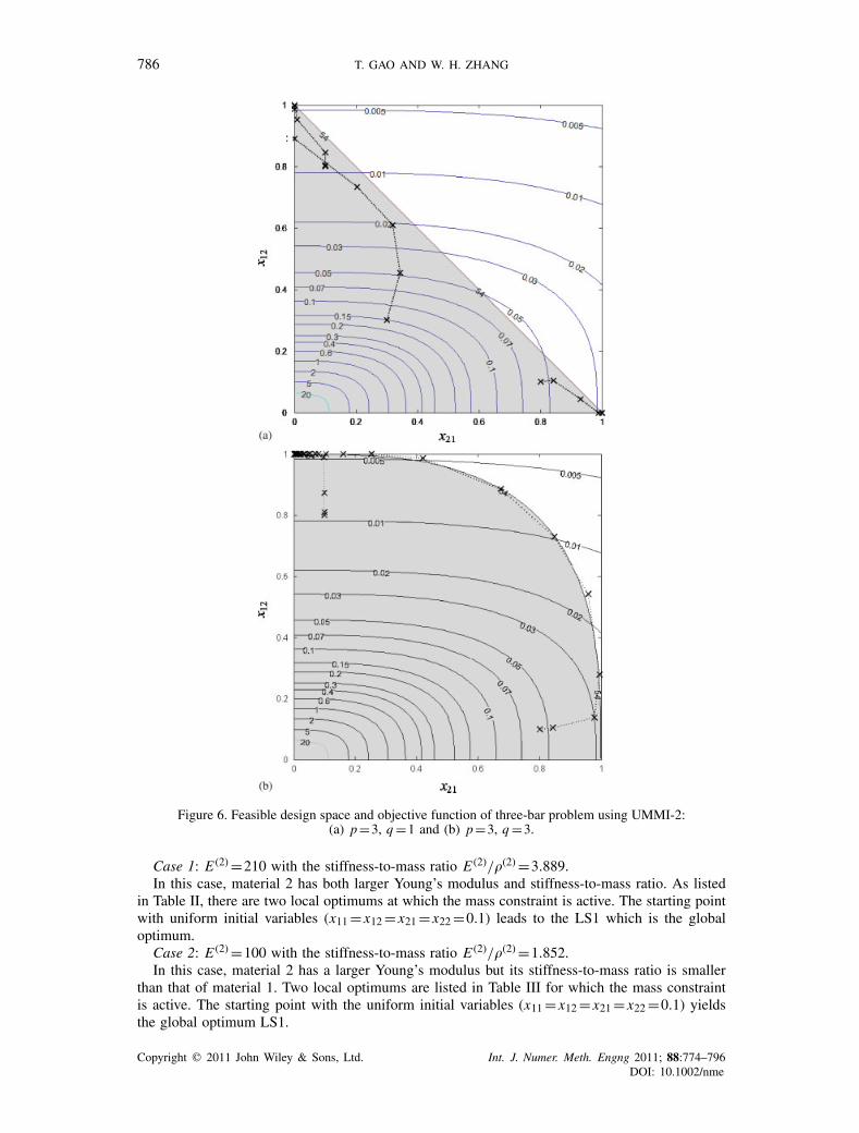
2m
3m
5m
5m
F
Figure 10. A loaded knee structure.
Figure 11. Optimization results of the loaded knee structure: (a) Material layout with VM1-VM3 C =9.02;(b) material layout with VM1 C =9.57; (c) material layout with VM3 C =10.77; and (d) VM1 Distribution
of the element Von Mises stress.
6.2. Knee structure
The considered knee structure is shown in Figure 10. It has a unit thickness and loaded undera vertical concentrated force (F =100kN). Suppose that M =30×103 kg and only the UMMI-2scheme is adopted. When VM1 and VM3 are available, both of them are present in the optimaldesign, as shown in Figure 11(a). Comparatively, the results with one prescribed single solidmaterial (VM1 or VM3) are shown in Figure 11(b) and (c), respectively. Correspondingly, thedistribution of the Von-Mises stress related to the solution given in Figure 11(b) is shown inFigure 11(d). Because the stress concentration occurs around the force action point, the inner cornerof the knee structure and the two vertical sticks, VM3 is locally placed in these areas as shown inFigure 11(a) due to its larger Young’s modulus. According to the compliance values of the opti-mization results, the design solution with both VM1 and VM3 is the best. This indicates that theproposed UMMI-2 scheme is efficient.
In all optimal configurations, it is found that some details exist. The reason is that the filteringcodes are terminated after tens of iterations to avoid the middle density or ‘mixed’ material in theobtained discrete optimization results.
Copyright � 2011 John Wiley & Sons, Ltd. Int. J. Numer. Meth. Engng 2011; 88:774–796DOI: 10.1002/nme

STRUCTURAL TOPOLOGY OPTIMIZATION WITH MULTIPHASE MATERIALS 791
Figure 12. Iteration histories of the loaded knee structure (VM1-VM3): (a) iteration histories of thecompliance and mass and (b) iteration histories of the volume fractions of the solid material phases.
Correspondingly, the iteration histories of the design problem with VM1-VM3 are plotted inFigure 12. Obviously, both the compliance and structure mass converge in a stable way, whereasthe volume fraction of each solid material phase changes in a non-monotonous way. In contrast,the iteration curve of the volume fraction is usually monotonous when a single solid material phaseis commonly used.
Now, studies are made about the influence of the upper bound of the mass constraint. As shownin Figure 13, with the successive relaxation of the upper bound of the mass constraint, the volumefraction of VM3 increases monotonously, whereas the volume fraction of VM1 first increases dueto its large stiffness-to-mass ratio and then decreases due to its small Young’s modulus. In otherwords, if more materials are allowable for a structure, stiff materials with high Young’s modulushave the priority to those with high stiffness-to-mass ratio. In the extreme case of M>60×103 kg,the optimal structure only consists of VM3. It can thus be said that the upper bound of the massconstraint influences not only the volume fraction of each material phase but also its existence.
Moreover, the influences of the upper bound on the optimal compliance are shown in Figure 14.Clearly, with the availability of two solid material phases, the design is always better than usinga single solid material phase because more candidate materials provide a large design space.
Another interesting thing is to compare the optimization results obtained with mass and volumeconstraints. To do this, suppose that the structure mass is less than 25.92×10³ kg. The upper bound
Copyright � 2011 John Wiley & Sons, Ltd. Int. J. Numer. Meth. Engng 2011; 88:774–796DOI: 10.1002/nme

792 T. GAO AND W. H. ZHANG
Figure 13. Influence of the upper bound of the mass constraint upon the volume fractions of the solidmaterials (VM1-VM3) in the optimal configuration.
Figure 14. Influence of the upper bound of the mass constraint upon thecompliance of the optimal configuration.
Figure 15. Comparisons of the optimization results under the mass andvolume constraints with the equal structure mass.
of the volume constraint can be correspondingly determined for VM3 if the upper bound of thevolume constraint of VM1 is fixed a priori. For different volume fractions of VM1, optimizationresults are plotted in Figure 15. The optimal solution with the mass constraint corresponds to thevolume fractions of VM1 and VM3 being 0.463 and 0.068, respectively. It can be seen that this
Copyright � 2011 John Wiley & Sons, Ltd. Int. J. Numer. Meth. Engng 2011; 88:774–796DOI: 10.1002/nme

STRUCTURAL TOPOLOGY OPTIMIZATION WITH MULTIPHASE MATERIALS 793
is the best solution among all possible ones using volume constraint in the sense of complianceminimization. In other words, the mass constraint always leads to a better solution than the volumeconstraint with the precondition of the same structure mass. Meanwhile, the percentage of eachsolid material phase will be automatically identified. In fact, the mass constraint has a moresignificant and important sense than the volume constraint in most engineering problems.
Here, theoretical demonstrations are made to reveal the relationship between the volumeconstraint and the mass constraint. Generally speaking, for a problem with the volume constraints,an arbitrary feasible solution {xij} satisfies
n∑i=1
Vi xij�V( j)
(32)
where V( j)
denotes the upper bound to the volume of solid material phase j . The multiplication ofboth sides by the density of solid material phase j , namely�( j), gives rise to(
n∑i=1
Vi xij
)�( j)�V
( j)�( j) (33)
Then, the summation of all solid materials can be stated as:m∑
j=1
n∑i=1
xij�( j)Vi�
m∑j=1
V( j)
�( j) (34)
Considering the prescribed structure mass, we have
m∑j=1
V( j)
�( j) = M (35)
The combination of Equations (34) and (35) yields
m∑j=1
n∑i=1
xij�( j)Vi�M (36)
This is just the mass constraint given in Equation (21). It means that any feasible solution ofthe optimization problem with volume constraint is also a feasible solution of the correspondingproblem with mass constraint. That is, the volume constraints defined by Equation (32) forma sub-design space of that defined by the mass constraint of Equation (36). This is why themass constraint has the advantage of reducing further the structural compliance over the volumeconstraints with the precondition of the same structure mass.
6.3. Problem with three solid material phases
Take again the knee structure shown in Figure 10 as an example. Assume that three solid materials(VM1, VM3 and VM4) are now available and UMMI-2 scheme is adopted. First, suppose thatonly the mass constraint is included with M =30×103 kg. As shown in Figure 16(a), the optimalstructure mainly consists of VM1 because its stiffness-to-mass ratio is the largest and the massconstraint is relatively severe. Compared with the results given in Figure 11(a), a stiffer structureis now obtained due to the availability of more candidate materials. If the volume fraction of VM1is further limited to 20% a priori and added as the volume constraint, the optimization result isshown in Figure 16 (b), where VM3 and VM4 play more important roles in the structure. Becausethe additional volume constraint of VM1 is a binding constraint that reduces the feasible designdomain of the optimization problem, the value of the objective function increases. Notice that thestructure mass always attains its upper bound in both cases.
6.4. Cyclic-symmetry structure
As shown in Figure 17, a cyclic-symmetry structure is partitioned into 12 identical cells along thecircumferential direction. The structure is clamped along the inner hole boundary and a concentrated
Copyright � 2011 John Wiley & Sons, Ltd. Int. J. Numer. Meth. Engng 2011; 88:774–796DOI: 10.1002/nme

794 T. GAO AND W. H. ZHANG
Figure 16. Optimization results with three-phase solid materials: (a) mass constraint C =8.845 VM1:55.5% VM3: 0.3% VM4: 4.5% and (b) mass constraint and volume constraint C =9.671 VM1: 20.0%
VM3: 15.3% VM4: 6.3%.
1m 3m
F
Figure 17. Cyclic-symmetry structure.
Figure 18. Optimization results of the cyclic-symmetry structure: (a) mass constraint C =6.74 (VM1:58.5%, VM3: 0%, VM4: 0%) and (b) mass constraint and volume constraint of VM1 C =8.43 (VM1:
30.0%, VM3: 14.3%, VM4: 0%).
tangential load (F =105 kN) is applied at the cross point between the outer boundary and thesymmetrical axis of one cell. Similar to the previous test, suppose that three solid materials (VM1,VM3 and VM4) are available and UMMI-2 scheme is adopted.
First, suppose M =40×103 kg. Only VM1 with the largest stiffness-to-mass ratio exists in theoptimal configuration as shown in Figure 18(a). Now, by adding the volume constraint of VM1with the upper bound of the volume fraction to be 0.3, the optimal configuration is shown inFigure 18(b). The gray and dark colors indicate VM1 and VM3, respectively. The structuralcompliance obviously increases due to the active volume constraint. In both cases, VM4 does notexist in the optimal structures although it is available.
Copyright � 2011 John Wiley & Sons, Ltd. Int. J. Numer. Meth. Engng 2011; 88:774–796DOI: 10.1002/nme

STRUCTURAL TOPOLOGY OPTIMIZATION WITH MULTIPHASE MATERIALS 795
7. CONCLUSIONS
In view of the lightweight design of advanced structures, a novel formulation of structural topologyoptimization with multiphase materials subjected to mass constraint is proposed. This formulationis studied in comparison with the common formulation with volume constraint. Basic propertiesof RMMI and UMMI material interpolation schemes are first discussed and both analytical andnumerical tests are carried out to show that UMMI-2 with fully uniform initial design variableshas the advantage of attaining a superior optimum solution. On the basis of UMMI-2, theoreticaldemonstrations point out that the volume constraint of linear form constitutes a subset of thefeasible design space defined by the mass constraint of linear form. Therefore, the latter is able toproduce the minimum compliance of all possible combinations of multiphase materials. Besides, itis found that at the optimized configuration, the volume fraction of each material phase is greatlyinfluenced by the mass constraint. When the upper bound of the mass constraint is relaxed for astructure, stiff materials with high Young’s modulus are dominant; when the upper bound of themass constraint is strictly tightened, materials with high stiffness-to-mass ratios become dominantfor an optimal structure layout.
From the development of this work, it is seen that the combination of UMMI-2 scheme togetherwith fully uniform initial variables and the convex programming methods provides an efficientapproach for the structural layout design of multiphase materials in static load case when the massis controlled. Meanwhile, due to its generality, this approach may be extended to the structuraldesign and microstructure design of multiphase materials in generalized load cases.
ACKNOWLEDGEMENTS
This work is supported by the National Natural Science Foundation of China (10925212, 90916027),Research Fund for the Doctoral Program of Higher Education of China (20106102110018) and 973Program (2011CB610304).
REFERENCES
1. Thomsen J. Topology optimization of structures composed of one or two materials. Structural and MultidisciplinaryOptimization 1992; 5(1):108–115.
2. Bendsøe MP, Sigmund O. Material interpolation schemes in topology optimization. Archive of Applied Mechanics1999; 69(9):635–654.
3. Sigmund O. Design of multiphysics actuators using topology optimization—part II: two-material structures.Computer Methods in Applied Mechanics and Engineering 2001; 190(49–50):6605–6627.
4. Sigmund O, Torquato S. Design of materials with extreme thermal expansion using a three-phase topologyoptimization method. Journal of the Mechanics and Physics of Solids 1997; 45(6):1037–1067.
5. Sun SP, Zhang WH. Multiple objective topology optimal design of multiphase microstructures. Acta MechanicaSinica 2006; 38(5):633–638.
6. Sun SP, Zhang WH. Investigation of perimeter control methods for structural topology optimization with multiphasematerials. Hangkong Xuebao/Acta Aeronautica et Astronautica Sinica 2006; 27:963–968.
7. Gao T, Zhang W-H. Topology optimization of multiphase material structures under design dependent pressureloads. International Journal for Simulation and Multidisciplinary Design Optimization 2009; 3(1):297–306.
8. Gao T, Zhang W. Topology optimization involving thermo-elastic stress loads. Structural and MultidisciplinaryOptimization 2010; 42(5):725–738.
9. Yin L, Ananthasuresh GK. Topology optimization of compliant mechanisms with multiple materials using a peakfunction material interpolation scheme. Structural and Multidisciplinary Optimization 2001; 23(1):49–62.
10. Wang MY, Zhou S. Synthesis of shape and topology of multi-material structures with a phase-field method.Journal of Computer-aided Materials Design 2004; 11(2):117–138.
11. Zhou S, Wang M. Multimaterial structural topology optimization with a generalized Cahn–Hilliard model ofmultiphase transition. Structural and Multidisciplinary Optimization 2007; 33(2):89–111.
12. Mei Y, Wang X. A level set method for structural topology optimization with multi-constraints and multi-materials.Acta Mechanica Sinica 2004; 20(5):507–518.
13. Jung D, Gea H. Design of an energy-absorbing structure using topology optimization with a multimaterial model.Structural and Multidisciplinary Optimization 2006; 32(3):251–257.
14. Han S-Y, Lee S-K. Development of a material mixing method based on evolutionary structural optimization.JSME International Journal Series A: Solid Mechanics and Material Engineering 2005; 48(3):132–135.
Copyright � 2011 John Wiley & Sons, Ltd. Int. J. Numer. Meth. Engng 2011; 88:774–796DOI: 10.1002/nme

796 T. GAO AND W. H. ZHANG
15. Stegmann J, Lund E. Discrete material optimization of general composite shell structures. International Journalfor Numerical Methods in Engineering 2005; 62:2009–2027.
16. Fleury C, Braibant V. Structural optimization: a new dual method using mixed variables. International Journalfor Numerical Methods in Engineering 1986; 23(3):409–428.
17. Svanberg K. The method of moving asymptotes—a new method for structural optimization. International Journalfor Numerical Methods in Engineering 1987; 24(2):359–373.
18. Svanberg K. A globally convergent version of mma without line search. First World Congress of Structural andMultidisciplinary Optimization, Goslar, Germany, 1995; 9–16.
19. Zhang W-H, Fleury C. A modification of convex approximation methods for structural optimization. Computersand Structures 1997; 64(1–4):89–95.
20. Haber RB, Jog CS, Bendsøe MP. A new approach to variable-topology shape design using a constraint onperimeter. Structural and Multidisciplinary Optimization 1996; 11(1):1–12.
21. Beckers M. Topology optimization using a dual method with discrete variables. Structural and MultidisciplinaryOptimization 1999; 17(1):14–24.
22. Petersson J, Sigmund O. Slope constrained topology optimization. International Journal for Numerical Methodsin Engineering 1998; 41(8):1417–1434.
23. Borrvall T. Topology optimization of elastic continua using restriction. Archives of Computational Methods inEngineering 2001; 8(4):351–385.
24. Sigmund O. A 99 line topology optimization code written in matlab. Structural and Multidisciplinary Optimization2001; 21(2):120–127.
25. Xu S, Cai Y, Cheng G. Volume preserving nonlinear density filter based on heaviside functions. Structural andMultidisciplinary Optimization 2010; 41(4):495–505.
26. Zhou M, Shyy YK, Thomas HL. Checkerboard and minimum member size control in topology optimization.Structural and Multidisciplinary Optimization 2001; 21:152–158.
27. Guest JK, Prévost JH, Belytschko T. Achieving minimum length scale in topology optimization using nodaldesign variables and projection functions. International Journal for Numerical Methods in Engineering 2004;61(2):238–254.
Copyright � 2011 John Wiley & Sons, Ltd. Int. J. Numer. Meth. Engng 2011; 88:774–796DOI: 10.1002/nme