A Low-Profile UHF SATCOM Antenna
5
IEEE TRANSACTIONS ON ANTENNAS AND PROPAGATION 1 A Low-Profile UHF SATCOM Antenna Gui Chao Huang, Student Member, IEEE and Magdy F. Iskander, Life Fellow, IEEE Abstract—A low-profile circularly polarized stacked patch antenna with U-slots was designed, fabricated and measured at 240 to 300 MHz for satellite and communications applications. U-slots on the driven patch is proposed and its design is optimized to improve the bandwidth of the antenna. In addition, the -10 dB return loss has been compromised in favor of a wider, stable and acceptable performance bandwidth. The proposed antenna has size of 0.36λc × 0.36λc × 0.035λc. A bandwidth of 22% and gain of 3.5 dBic with axial ratio below 2.5 dB are achieved in the 240 to 300 MHz band. Index Terms— Circularly polarized, patch antenna, UHF SATCOM I. INTRODUCTION For satellite communication, circularly polarized antennas are often used since they have the ability to mitigate the multipath effects and provide additional freedom to the orientation angle of the transmitting and receiving antennas. In modern communication system, circularly polarized antennas with compact size are desired for overall size reduction and mobility improvement of the communication systems, especially at lower frequencies. Circularly polarized antennas such as spiral antennas and cross-dipole antennas support wideband operations, however, they often require a ground plane to provide unidirectional radiation pattern, which increase the overall size of the antenna. On the other hand, patch antennas are desirable for miniature antenna design as they have the advantages of low profile and easy to fabricate. The challenge is that circularly polarized patch antennas tend to have narrow bandwidth, typically less than 8% [1–4]. Considerable research efforts have been conducted to improve the bandwidth of patch antennas, and many resulted in increasing heights of these antennas [5–9]. For examples, a bandwidth of 16.8% was achieved on a stacked patch antenna fed by a meandered probe with antenna size of 0.62λc × 0.62λc × 0.14λc [5], where λc is the free-space wavelength at the center frequency of the antenna’s operating frequency band. By utilizing parasitic strips and capacitive-coupled feed, a bandwidth of 24% was obtained in [6], with the antenna size of 0.98λc × 0.98λc × 0.13λc. Other miniaturized patch antenna designs were often reported in narrower bandwidth [10–14]. For examples, the miniaturized patch antenna design in [11] with size of 0.35λc × 0.35λc × 0.03λc was reported to have a bandwidth of 3.7%. In [12], a patch antenna design integrated with metamaterial structures was able to reduce the antenna size to 0.177λc × 0.181λc × 0.025λc with reported bandwidth of 1.46%. In this paper, a novel low profile circularly polarized stacked patch antenna with two small U-slots is proposed for satellite communications at 240–300 MHz (22% bandwidth). Beside the frequency band requirement, the additional main requirements for the proposed antenna was the maximum size of the antenna, as it needs to be limited to 400 × 400 × 39 mm 3 (0.36λc × 0.36λc × 0.035λc) and the antenna gain needs to be greater than -2 dBic in between the ±60° angle on the broadside direction. It is challenging to maintain such a wide bandwidth while complying with the given limited antenna size requirement. Miniaturized patch antenna designs are often reported to have bandwidth less than 4% [10–14]. To achieve the 22% bandwidth, This work is sponsored by National Science Foundation, Grand No. ECCS 1443875. C. Huang and M. F. Iskander are with the Hawaii Center for Advanced Communications, College of Engineering, University of Hawaii at Manoa, Honolulu, HI 96822, USA. [email protected] and [email protected]. two small U-slots on the driven patch together with a 90° hybrid coupler feed were proposed to improve the bandwidth of the antenna. The developed circularly polarized patch antenna design, therefore, achieved superior characteristics including 22% bandwidth and 3.5 dBic average gain, compared with other patch antenna designs of similar sizes. In section II of this paper, we describe the antenna design and results from simulation studies, and in section III results from experimental measurements are discussed. Section IV includes observations and concluding remarks. II. ANTENNA DESIGN In patch antenna design, air gap or substrate with low dielectric constant can help to improve the bandwidth of the antenna [7]. This, however, results in an increase in patch’s size, close to half- wavelength, which is too large for meeting miniaturization size requirements. To miniaturize the size of the antenna, substrate with high dielectric property was proposed for the antenna design. In addition, a stacked patch setup was used for wide S11 bandwidth. A dual fed configuration was also implemented in the proposed antenna design as dual fed or multiple fed techniques can provide wider axial ratio bandwidth [7, 8]. Figure 1 shows the initial design of the proposed dual-fed stacked patch antenna design. The driven patch and the parasitic patch were printed on the top of the substrates, where the driven patch was fed by two copper probes from the bottom. There was a small air gap in between the substrate layers. The air gap was for fabrication purpose, which provide space for the solder to bound the driven patch and the copper probes together. To determine which dielectric material is more suitable for the antenna design, different dielectric materials with high dielectric constant were examined, which include FR4, TC600 (Rogers), and TMM10i (Rogers). The dielectric materials have dielectric constant of 4.4, 6.15 and 9.8, respectively. Simulations of the patch antenna with different dielectric materials were performed in HFSS. In the simulation setup, the copper probes were excited 90° out of phase to achieve circularly polarization. The diameter of the probes was set to 3mm. The dimensions of the other design parameter are shown in Table I. The dimensions were adjusted accordingly so that the operating frequency of the antenna is close to the center frequency of the targeting frequency band. Figure 2 shows the simulation results of the patch antenna design on different substrate materials. Narrow S11 bandwidths (< 6%) were obtained in all cases. The difference in bandwidth between the substrate materials is around 1%. Nevertheless, antenna design with FR4 has the widest bandwidth. However, for a slight reduction in size and to avoid the variation of FR4, the TC600 substrate was chosen in the further development of the antenna design. Fig. 1. Initial stacked patch antenna design.
Transcript of A Low-Profile UHF SATCOM Antenna

IEEE TRANSACTIONS ON ANTENNAS AND PROPAGATION 1
A Low-Profile UHF SATCOM Antenna Gui Chao Huang, Student Member, IEEE and Magdy F. Iskander, Life Fellow, IEEE
Abstract—A low-profile circularly polarized stacked patch antenna with U-slots was designed, fabricated and measured at 240 to 300 MHz for satellite and communications applications. U-slots on the driven patch is proposed and its design is optimized to improve the bandwidth of the antenna. In addition, the -10 dB return loss has been compromised in favor of a wider, stable and acceptable performance bandwidth. The proposed antenna has size of 0.36λc × 0.36λc × 0.035λc. A bandwidth of 22% and gain of 3.5 dBic with axial ratio below 2.5 dB are achieved in the 240 to 300 MHz band.
Index Terms— Circularly polarized, patch antenna, UHF SATCOM
I. INTRODUCTION For satellite communication, circularly polarized antennas are
often used since they have the ability to mitigate the multipath effects and provide additional freedom to the orientation angle of the transmitting and receiving antennas. In modern communication system, circularly polarized antennas with compact size are desired for overall size reduction and mobility improvement of the communication systems, especially at lower frequencies. Circularly polarized antennas such as spiral antennas and cross-dipole antennas support wideband operations, however, they often require a ground plane to provide unidirectional radiation pattern, which increase the overall size of the antenna. On the other hand, patch antennas are desirable for miniature antenna design as they have the advantages of low profile and easy to fabricate. The challenge is that circularly polarized patch antennas tend to have narrow bandwidth, typically less than 8% [1–4]. Considerable research efforts have been conducted to improve the bandwidth of patch antennas, and many resulted in increasing heights of these antennas [5–9]. For examples, a bandwidth of 16.8% was achieved on a stacked patch antenna fed by a meandered probe with antenna size of 0.62λc × 0.62λc × 0.14λc
[5], where λc is the free-space wavelength at the center frequency of the antenna’s operating frequency band. By utilizing parasitic strips and capacitive-coupled feed, a bandwidth of 24% was obtained in [6], with the antenna size of 0.98λc × 0.98λc × 0.13λc. Other miniaturized patch antenna designs were often reported in narrower bandwidth [10–14]. For examples, the miniaturized patch antenna design in [11] with size of 0.35λc × 0.35λc × 0.03λc was reported to have a bandwidth of 3.7%. In [12], a patch antenna design integrated with metamaterial structures was able to reduce the antenna size to 0.177λc × 0.181λc × 0.025λc with reported bandwidth of 1.46%.
In this paper, a novel low profile circularly polarized stacked patch antenna with two small U-slots is proposed for satellite communications at 240–300 MHz (22% bandwidth). Beside the frequency band requirement, the additional main requirements for the proposed antenna was the maximum size of the antenna, as it needs to be limited to 400 × 400 × 39 mm3 (0.36λc × 0.36λc × 0.035λc) and the antenna gain needs to be greater than -2 dBic in between the ±60° angle on the broadside direction. It is challenging to maintain such a wide bandwidth while complying with the given limited antenna size requirement. Miniaturized patch antenna designs are often reported to have bandwidth less than 4% [10–14]. To achieve the 22% bandwidth,
This work is sponsored by National Science Foundation, Grand No. ECCS 1443875. C. Huang and M. F. Iskander are with the Hawaii Center for Advanced Communications, College of Engineering, University of Hawaii at Manoa, Honolulu, HI 96822, USA. [email protected] and [email protected].
two small U-slots on the driven patch together with a 90° hybrid coupler feed were proposed to improve the bandwidth of the antenna. The developed circularly polarized patch antenna design, therefore, achieved superior characteristics including 22% bandwidth and 3.5 dBic average gain, compared with other patch antenna designs of similar sizes. In section II of this paper, we describe the antenna design and results from simulation studies, and in section III results from experimental measurements are discussed. Section IV includes observations and concluding remarks.
II. ANTENNA DESIGN
In patch antenna design, air gap or substrate with low dielectric constant can help to improve the bandwidth of the antenna [7]. This, however, results in an increase in patch’s size, close to half-wavelength, which is too large for meeting miniaturization size requirements. To miniaturize the size of the antenna, substrate with high dielectric property was proposed for the antenna design. In addition, a stacked patch setup was used for wide S11 bandwidth. A dual fed configuration was also implemented in the proposed antenna design as dual fed or multiple fed techniques can provide wider axial ratio bandwidth [7, 8]. Figure 1 shows the initial design of the proposed dual-fed stacked patch antenna design. The driven patch and the parasitic patch were printed on the top of the substrates, where the driven patch was fed by two copper probes from the bottom. There was a small air gap in between the substrate layers. The air gap was for fabrication purpose, which provide space for the solder to bound the driven patch and the copper probes together. To determine which dielectric material is more suitable for the antenna design, different dielectric materials with high dielectric constant were examined, which include FR4, TC600 (Rogers), and TMM10i (Rogers). The dielectric materials have dielectric constant of 4.4, 6.15 and 9.8, respectively. Simulations of the patch antenna with different dielectric materials were performed in HFSS. In the simulation setup, the copper probes were excited 90° out of phase to achieve circularly polarization. The diameter of the probes was set to 3mm. The dimensions of the other design parameter are shown in Table I. The dimensions were adjusted accordingly so that the operating frequency of the antenna is close to the center frequency of the targeting frequency band. Figure 2 shows the simulation results of the patch antenna design on different substrate materials. Narrow S11 bandwidths (< 6%) were obtained in all cases. The difference in bandwidth between the substrate materials is around 1%. Nevertheless, antenna design with FR4 has the widest bandwidth. However, for a slight reduction in size and to avoid the variation of FR4, the TC600 substrate was chosen in the further development of the antenna design.
Fig. 1. Initial stacked patch antenna design.

IEEE TRANSACTIONS ON ANTENNAS AND PROPAGATION 1
To improve the bandwidth of the antenna, U-slots on the driven patch were proposed. Patch antennas with U-slot had been reported to have wider bandwidth than conventional patch antenna design, where the U-slot covers a large portion of the patch [10, 15]. For the proposed antenna, due to the dual-fed structure, new approach was proposed, which two small U-slots were created around the feeding probes as shown in Fig. 3. Beside the U-slots, a substrate layer (Rogers RO4350B) with dielectric constant of 3.66 and thickness of 0.762 mm was also added to the bottom of the antenna for matching and feeding networks implementation. The dimensions of the U-slots were optimized. Table II shows the dimensions of the proposed antenna design with the optimized U-slots. Parametric studies on the effect of the slot length, slot width and the position of the U-slots were also performed and the simulated S11 results on Smith chart are shown in Fig. 4. In Figure 4, the labeled dimensions in the legends are the varying dimensions, the rest of dimensions of the antenna are the same as the dimensions in Table II. Figures 4a and 4b show the effect of the U-slots in different length. In Fig. 4a, the length of the middle portion of the U-slots was changed by changing u1 and u2 (dimension labels in Fig. 3) together. In Fig. 4b, the length of left
and right sides of the U-slots were changed by changing u3 and u5 together. Changing lengths of both sections of the U-slot design affect the upper frequencies limit, and the input impedance drifts towards capacitive values at 310 MHz. At these upper frequencies the dimensions of the U-slots become appreciable fraction of a wavelength, and this results in more performance sensitivity to changes in dimensions. In Fig. 4c, the slot width of the U-slots was changed, where u1 and u3 were changed while u2 was 36mm and u5 was 32 mm. Similar to the slot length, with the increase of the slot width, the upper frequency portion of the curve continued to shift downward. In Fig. 4d, the position of the U-slots was changed by changing u4. It is shown that shifting the U-slots towards the edge of the driven patch, results in increasing the real part of the input impedance of the antenna. This is due to a decrease in the conductive area with decrease in u4 dimension. The effect of the thickness of the substrates supporting the driven and the parasitic patches was also studied. In this case, due to the limiting dimension, the total thickness of the two substrates was kept to be 37.2 mm. Figure 5
TABLE I DIMENSIONS OF THE INITIAL PATCH ANTENNA DESIGN ON DIFFERENT
SUBSTRATES (IN MILLIMETERS). w1 w2 d h1 h2 h3 g
FR4 215 254 96.5 22 0.8 15.2 400 TC600 190 217 109 18 0.8 19.2 400
TMM10i 148 172 130 18 0.8 19.2 400
Fig. 2. Similated S11 of the initial patch antenna design on three different substrates.
(a)
(b)
Fig. 3. Schematic of the proposed antenna design with U-slots: (a) Isometric view. (b) Top view of the driven patch.
TABLE II DIMENSIONS OF THE PROPOSED PATCH ANTENNA DESIGN (IN MILLIMETERS)
w1 w2 h0 h1 h2 h3 d 190 217 0.762 25 0.8 12.2 30 u1 u2 u3 u4 u5 g 42 36 41 15 32 400
(a)
(b)
(c)
(d)
Fig. 4. Simulated S11 of the antenna when the U-slots in different dimensions: (a) Different slot length, changing u1 and u2. (b) Different slot length, changing u3 and u5. (c) Different slot width, changing u1 and u3. (d) Different position, changing u4.
Fig. 5. Simulated S11 of the antenna with different substrate thickness.

IEEE TRANSACTIONS ON ANTENNAS AND PROPAGATION 5
shows the simulation result of the antenna substrates in different thickness. As it may be seen in Fig. 5, the radius of the S11 locus decreases and the center of the locus region shifts toward the upper left direction when the thickness of the substrate supporting the driven patch decreases. Fig. 5, also reveals that the upper frequency end of the curve shifts far away from the locus region, thus indicating decrease in the bandwidth.
Based on results from the parametric study, dimensions of the U-slots and height of the substrates were chosen so that the S11 curve forms a circle over the frequency band of interest and shifts the S11 curve over the matching circle region. The obtained optimized values are given in Table II. Figure 6 shows the simulated S11 of the proposed antenna design with and without the U-slots using the optimized values in Table II. It shows that the U-slots helped in concentrating the S11 curve and shifted it toward the matching circle region. Based on the figure, the S11 curve is on the upper side of the Smith chart, which indicates the input impedance of the antenna has high inductive reactance. The U-slots don’t have much effect on the lower frequencies, thus to compensate the inductive reactance, two 13 pF capacitors were added and connected in series with each feeding probe as indicated in Fig. 3a. As a result, the S11 curve was shifted downward and it surrounds the center of the Smith chart as shown in Fig. 6. Although the S11 curve is around the center of the Smith chart, the radius of the curve is relatively large. The narrow band -10 dB S11 is then compromised for a stable S11 value over the frequency band of interested. To this end, the other parameters of the antenna are examined to see if the current design has achieved the acceptable performance.
Figure 7 shows the simulated S11 of the antenna with U-slots in decibel scale, and where it may be seen that the S11 ranges from -7 to -5 dB over the 240–300 MHz frequency band. The realized RHCP gain and axial for the antenna design are also shown in Fig. 7, where the realized RHCP gain is around 4 dBic and the axial ratio is less than 3 dB over the entire band of interest. For comparison, the simulated results of the antenna design without U-slots are also shown in Fig. 7. It shows that the antenna design without U-Slots has
S11 below -10 dB and slightly higher gain (about 5.5 dBic). However, the bandwidth of the antenna is narrow and the gain decreases dramatically at frequencies outside the -10 dB S11 band. The radiation patterns of the antenna with U-slots in X-Z and Y-Z planes are shown in Fig. 8. As shown in Fig. 8, stable radiation patterns were obtained. The gain of the antenna is over -0.6 dBic at the ±60° angle in both planes, which is higher than the -2 dBic design requirement. The cross-polarization level is more than 15 dB in the broadside direction. Based on these simulation results, it is clear that beside the S11, other parameters of the antenna have met the design requirements over the specified frequency band, including the gain and axial ratio, as well as the dimension of the antenna. Once again, it is well known that the -10 dB S11 could be achieved at the expense of narrower bandwidth, hence, by compromising the -10 dB S11 for a wider bandwidth, acceptable stable radiation characteristics were obtained over a wider bandwidth. To improve the overall S11 of the antenna, a feed system was designed and will be described next.
A 90° hybrid coupler feeding network was designed on the Rogers RO4350B substrate layer of the antenna to feed the feeding probes with phase offset of 90°. Other feeding networks such as T-junction microstrip or Wilkinson power divider can also be used to feed the antenna. However, due to the high S11 value of this antenna, the unique feature of the 90° hybrid coupler, which reflected energy from the output ports is transmitted to the isolation port [16], is used
Fig. 6. Simulated S11 of the proposed antenna design on Smith chart.
Fig. 7. Simulated S11, realized RHCP gain and axial ratio of the proposed antenna design with and without U-slots.
Fig. 8. Simulated radiation patterns in X-Z plane and Y-Z plane at different frequencies.
Fig. 9. Schematic of the 90° hybrid coupler.
Fig. 10. Simulation results of the 90° hybrid coupler.

IEEE TRANSACTIONS ON ANTENNAS AND PROPAGATION 5
to improve the S11 of the antenna. Figure 9 shows the schematic and the dimensions of the hybrid coupler. The impedance on the input and output ports of the 90° hybrid coupler were designed to be 50 Ohm. The microstrip lines were meandered to reduce the size of the coupler. Figure 10 shows the simulated and measured results of the hybrid coupler. The measured results agree well with the simulated results, which the S11 is below -10 dB, the insertion loss is less than 1 dB and phase difference between S31 and S41 is stable at around -90° over the frequency band of interest.
Figs. 11 to 14 show the simulation results of the proposed antenna design integrated with the 90° hybrid coupler. The output ports (Ports 3 and 4) are used to feed the antenna and the isolation port (Port 2) is terminated with a 50 Ohm resistor. As expected, the S11 of the antenna is improved by the 90° hybrid coupler, which is now below -10 dB over the 240–300 MHz frequency band. The antenna gain in Fig. 11 is slightly decreased compare to the gain in Fig. 7, and now ranges from 3.2 to 4.3 dBic, due to the insertion loss from the 90° hybrid coupler. The axial ratio of the antenna is improved slightly; it is below 2.5 dB as shown in Fig. 11. Figure 12 shows the radiation pattern of the antenna. The minimum gain of the antenna at the ±60° angle is reduced to -1.5 dBic. The cross-polarization level is improved to more than 20 dB in the broadside direction. The improvements in the axial ratio and the cross-polarization level are due to the fact that hybrid couplers improve the impedance matching
(reduce mismatching effects, through use of isolation port) and also improve the feed balance between the two feeding ports for the two polarization components. Figure 13 shows the axial ratio of the antenna in the X-Z plane. The axial ratio is below 3 dB in the broadside within the ±68° angle which is suitable for satellite commination applications. Figure 14 shows the radiation efficiency of the antenna, which ranges from 57% to 78%.
III. MEASUREMENT RESULTS The antenna was fabricated and measured. The top and bottom
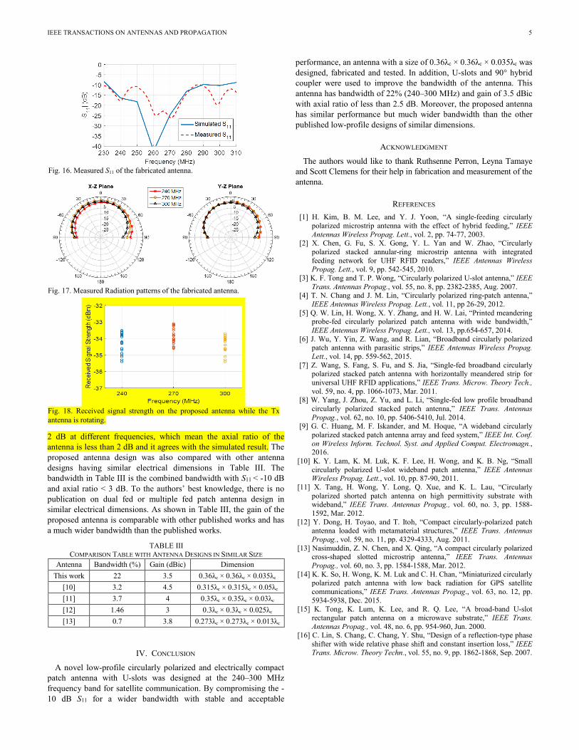
views of the fabricated antenna are shown in Fig. 15. Figure 16 shows the measured S11 result together with the simulated result. The measured S11 is less than -10 dB across the frequency band of interest and agreed with the simulated S11. There are some discrepancies in the region where good impedance matching was achieved and this could be due to the significantly small values of reflections (-20 dB), environmental effects in measurements and idealized environment in simulation. Radiation pattern measurement of the antenna was performed in an outdoor facility. In these measurements, a linearly polarized UHF antenna was used as a Tx antenna; the fabricated antenna was used as the Rx antenna. The distance between the Tx and Rx antenna was 46 feet. A portable Anritsu spectrum analyzer was used to measure the received power on the Rx antenna. A linearly polarized log-periodic antenna (model: SAS-512-2) from A.H. Systems, Inc. was also used as a Rx antenna for gain reference. The measured radiation pattern of the antenna based on the aforementioned setup is shown in Fig. 17. The antenna gain in the broadside direction is around 0.5 dB. The gain at the ±60° angle is above -5 dB. As the Tx antenna is a linearly polarized antenna, therefore there is a 3-dB loss in the polarization mismatch, and the circularly polarized gain of the fabricated antenna is expected to be about 3 dB higher. A brief measurement on the axial ratio of the antenna in the broadside direction was performed by rotating the linearly polarized Tx antenna 180° with step size of 10°. Figure 18 shows the received signal strength while the Tx antenna is rotated at different angles. The received signal strength varies within
Fig. 11. Simulated S11, realized RHCP gain and axial ratio of the proposed antenna fed by the 90° hybrid coupler.
Fig. 12. Simulated radiation patterns of the proposed antenna design fed by the 90° hybrid coupler.
Fig. 13. Simulated axial ratio of the proposed antenna design fed by the 90° hybrid coupler in the X-Z plane.
Fig. 14. Simulated radiation efficiency of the proposed antenna design fed by the 90° hybrid coupler.
(a)
(b)
Fig. 15. Fabricated antenna. (a) Top view. (b) Bottom view.
IEEE TRANSACTIONS ON ANTENNAS AND PROPAGATION 5
2 dB at different frequencies, which mean the axial ratio of the antenna is less than 2 dB and it agrees with the simulated result. The proposed antenna design was also compared with other antenna designs having similar electrical dimensions in Table III. The bandwidth in Table III is the combined bandwidth with S11 < -10 dB and axial ratio < 3 dB. To the authors’ best knowledge, there is no publication on dual fed or multiple fed patch antenna design in similar electrical dimensions. As shown in Table III, the gain of the proposed antenna is comparable with other published works and has a much wider bandwidth than the published works.
IV. CONCLUSION
A novel low-profile circularly polarized and electrically compact patch antenna with U-slots was designed at the 240–300 MHz frequency band for satellite communication. By compromising the -10 dB S11 for a wider bandwidth with stable and acceptable
performance, an antenna with a size of 0.36λc × 0.36λc × 0.035λc was designed, fabricated and tested. In addition, U-slots and 90° hybrid coupler were used to improve the bandwidth of the antenna. This antenna has bandwidth of 22% (240–300 MHz) and gain of 3.5 dBic with axial ratio of less than 2.5 dB. Moreover, the proposed antenna has similar performance but much wider bandwidth than the other published low-profile designs of similar dimensions.
ACKNOWLEDGMENT The authors would like to thank Ruthsenne Perron, Leyna Tamaye
and Scott Clemens for their help in fabrication and measurement of the antenna.
REFERENCES [1] H. Kim, B. M. Lee, and Y. J. Yoon, “A single-feeding circularly
polarized microstrip antenna with the effect of hybrid feeding,” IEEE Antennas Wireless Propag. Lett., vol. 2, pp. 74-77, 2003.
[2] X. Chen, G. Fu, S. X. Gong, Y. L. Yan and W. Zhao, “Circularly polarized stacked annular-ring microstrip antenna with integrated feeding network for UHF RFID readers,” IEEE Antennas Wireless Propag. Lett., vol. 9, pp. 542-545, 2010.
[3] K. F. Tong and T. P. Wong, “Circularly polarized U-slot antenna,” IEEE Trans. Antennas Propag., vol. 55, no. 8, pp. 2382-2385, Aug. 2007.
[4] T. N. Chang and J. M. Lin, “Circularly polarized ring-patch antenna,” IEEE Antennas Wireless Propag. Lett., vol. 11, pp 26-29, 2012.
[5] Q. W. Lin, H. Wong, X. Y. Zhang, and H. W. Lai, “Printed meandering probe-fed circularly polarized patch antenna with wide bandwidth,” IEEE Antennas Wireless Propag. Lett., vol. 13, pp.654-657, 2014.
[6] J. Wu, Y. Yin, Z. Wang, and R. Lian, “Broadband circularly polarized patch antenna with parasitic strips,” IEEE Antennas Wireless Propag. Lett., vol. 14, pp. 559-562, 2015.
[7] Z. Wang, S. Fang, S. Fu, and S. Jia, “Single-fed broadband circularly polarized stacked patch antenna with horizontally meandered strip for universal UHF RFID applications,” IEEE Trans. Microw. Theory Tech., vol. 59, no. 4, pp. 1066-1073, Mar. 2011.
[8] W. Yang, J. Zhou, Z. Yu, and L. Li, “Single-fed low profile broadband circularly polarized stacked patch antenna,” IEEE Trans. Antennas Propag., vol. 62, no. 10, pp. 5406-5410, Jul. 2014.
[9] G. C. Huang, M. F. Iskander, and M. Hoque, “A wideband circularly polarized stacked patch antenna array and feed system,” IEEE Int. Conf. on Wireless Inform. Technol. Syst. and Applied Comput. Electromagn., 2016.
[10] K. Y. Lam, K. M. Luk, K. F. Lee, H. Wong, and K. B. Ng, “Small circularly polarized U-slot wideband patch antenna,” IEEE Antennas Wireless Propag. Lett., vol. 10, pp. 87-90, 2011.
[11] X. Tang, H. Wong, Y. Long, Q. Xue, and K. L. Lau, “Circularly polarized shorted patch antenna on high permittivity substrate with wideband,” IEEE Trans. Antennas Propag., vol. 60, no. 3, pp. 1588-1592, Mar. 2012.
[12] Y. Dong, H. Toyao, and T. Itoh, “Compact circularly-polarized patch antenna loaded with metamaterial structures,” IEEE Trans. Antennas Propag., vol. 59, no. 11, pp. 4329-4333, Aug. 2011.
[13] Nasimuddin, Z. N. Chen, and X. Qing, “A compact circularly polarized cross-shaped slotted microstrip antenna,” IEEE Trans. Antennas Propag., vol. 60, no. 3, pp. 1584-1588, Mar. 2012.
[14] K. K. So, H. Wong, K. M. Luk and C. H. Chan, “Miniaturized circularly polarized patch antenna with low back radiation for GPS satellite communications,” IEEE Trans. Antennas Propag., vol. 63, no. 12, pp. 5934-5938, Dec. 2015.
[15] K. Tong, K. Lum, K. Lee, and R. Q. Lee, “A broad-band U-slot rectangular patch antenna on a microwave substrate,” IEEE Trans. Antennas Propag., vol. 48, no. 6, pp. 954-960, Jun. 2000.
[16] C. Lin, S. Chang, C. Chang, Y. Shu, “Design of a reflection-type phase shifter with wide relative phase shift and constant insertion loss,” IEEE Trans. Microw. Theory Techn., vol. 55, no. 9, pp. 1862-1868, Sep. 2007.
Fig. 16. Measured S11 of the fabricated antenna.
Fig. 17. Measured Radiation patterns of the fabricated antenna.
TABLE III COMPARISON TABLE WITH ANTENNA DESIGNS IN SIMILAR SIZE
Antenna Bandwidth (%) Gain (dBic) Dimension This work 22 3.5 0.36λc × 0.36λc × 0.035λc
[10] 3.2 4.5 0.315λc × 0.315λc × 0.05λc [11] 3.7 4 0.35λc × 0.35λc × 0.03λc [12] 1.46 3 0.3λc × 0.3λc × 0.025λc [13] 0.7 3.8 0.273λc × 0.273λc × 0.013λc
Fig. 18. Received signal strength on the proposed antenna while the Tx antenna is rotating.