MAX30101 Hig-Sensitivity Plse Oimeter an Heart-Rate Sensor ...
A Low Cost Optical Sensor Based Heart RateMonitoring System
∗Mohammad Nasim Imtiaz Khan, Dewan Fahim Noor, Md. Jubaer Hossain Pantho, Tahmid Syed Abtahi,Farhana Parveen and Mohammed Imamul Hassan Bhuiyan
Department of Electrical and Electronic EngineeringBangladesh University of Engineering and Technology, Dhaka–1000, Bangladesh
Email: ∗[email protected]
Abstract—Heart rate exhibiting direct proportional character-istics with change in blood volume during heart beats can be mea-sured by modeling an analog and digital manipulation scheme. Amodel of a single Microcontroller chip based heart beat counter,capable of data storage and suitable for remote communicationvia Bluetooth, would be designed and implemented and checkedfor contrast with a commercial heart beat per minute (BPM)counter.
Index Terms—Heart Rate, Optical Sensor, Microcontroller,Bluetooth.
I. INTRODUCTION
Heart Rate, determined by the number of times heart beatsin a minute, is substantial, as it gives information on the overallphysical condition of the body. In case of patients sufferingfrom diseases, continuous or routine measurement of heart rateis very important. Analysis of heart rate would help maintainhealth, diagnose and detect coronary diseases [1], [2].
Heart rate is commonly measured by doctors by feeling andcounting the pulse of the pulsating arterial blood in suitableparts of the body such as wrist and neck. Electrocardiograph(ECG) provides an accurate and reliable method of heartrate counting. Electrical pulses from the heart are sensed,plotted and heart rate can be measured with maximum pre-cision by studying the graph. For example Food and DrugAdministration (FDA) approved InstantCheck ECG from Winhealth [3], [4] simultaneously shows heart rate, ST Segment(ST), QRS Interval (QRS). Additionally the device facilitatesdata transmission over the internet. However, the device issophisticated and may require expert assistance to operate. Itscost is around 530 USD which is expensive for the generalmass.
Heart rate can also be measured by seismocardiogramwhere body vibration is analyzed [5]. But the device is bulkyin size. Commercially many heart beat measuring kits areavailable. For an example, widely used FDA approved DigitalAutomatic Blood Pressure Monitor from OMRON [6] providesmeasurement of blood pressure along with heart beat perminute. It senses pulses from pulsating arterial blood flow withthe help of pressure sensors. The drawback of this kit is thatit is bulky in size and restricts free movement of the bodyand does not provide any remote communication. Its cost isaround 120 USD which is expensive and not affordable by the
general mass in countries like Bangladesh. Another populardevice named Heart Rate Monitor Ring manufactured by WinHealth [7] provides a real-time heart rate monitoring. It isworn in the finger and is portable. However, the device hasno memory storage system and it is not equipped with remotecommunication scheme such as Bluetooth communication.
In [8], [9] models of heart rate counter have been designedand implemented based on analyzing infrared light reflectionfrom body parts. In [9] a LCD display shows a change ofheart rate over a time period. However, it does not facilitateremote communication such as Bluetooth communication. ABluetooth communication scheme would allow data transfer toa cellular phone and use the existing cellular network to trans-mit data. Therefore, it would allow remote communication inany place within cellular network.
This paper proposes a design and implementation of asingle Microcontroller based heart rate measuring device thatintegrates most of the key features of the aforementioneddevices and models. The device is compact in size, energyefficient, portable, capable of data storage and well suited forcommunicating with an external remote device via Bluetoothand cellular communication in case of a medical emergency orroutine. The designed device is based on analyzing the changein level of reflected light after manually projecting infraredlight into suitable body parts such as fingertip, wrist or templearea of the head. It also has automatic calibration system tomeasure the heart rate of both infants and adults. The deviceis easy to use, inexpensive and affordable by the general mass.
II. PROPOSED SYSTEM
The proposed system is based on a single Microcontrollerchip that utilizes change in amount of reflection of light sensedby a photo transistor. The basic block diagram of the proposedsystem is given in Fig. 1.
The whole system consists of two parts. Data acquisitionpart, comprising first three blocks of the block diagram anddata processing part.
In data acquisition unit, infrared ray (IR) is projected on thefingertip with an IR transmitter. The arrangement is shown inFig. 2.
A photo transistor is used to sense the reflected light. Signalreceived by the photo transistor is very weak and perturbed byhigh frequency noise. In order for this signal to be processed

Fig. 1. Block Diagram
Fig. 2. Arrangement of Transmitter-Receiver Pair
in Microcontroller, it is needed to eliminate undesired noise.Furthermore, the signal level is to be raised to a satisfactorylevel so that the spikes coming from the photo transistorduring each time the heart beats can be distinguished properlyby the Microcontroller. For noise reduction and amplificationpurpose, the circuit arrangement in Fig. 3 is used.
Here reflection method is used as it serves better perfor-mance. The received signal is passed through two consecutive
Fig. 3. Noise Reduction and Amplification
Fig. 4. Digitization
filters to block dc components. Then two stage amplification[10], [11] is done, where signal components below a definitecut-off frequency are amplified. For this amplification purposeOP-AMP LM324 with class A output stage [12] is used thataltogether amplifies the original signal almost ten thousandtimes. Thus high frequency components (ripple or noise) areautomatically attenuated throughout this amplification process.
In this system, gain of each stage is up to 101.The cut offfrequency of the low pass filter, determined by (1) is 2.34 Hz.Corresponding maximum measurable heart rate is calculatedas, 2.34 × 60 ∼= 140 BPM.
fc =1
2πR7C2(1)
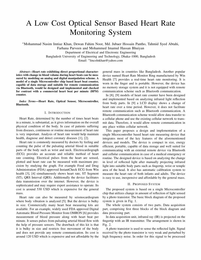
After noise being properly attenuated, the signal is fed tothe Microcontroller where the data processing is done byconverting the analog signal to digital one as shown in Fig. 4.These digital bits are now suitable for the Microcontroller tocount the number of heart beats. Flow chart concerning dataprocessing within the Microcontroller is illustrated in Fig. 5.
III. ALGORITHM
ATtiny45V [13] Microcontroller is used as the programmerfor measuring heart rate. A total of 20 seconds is usedeach time for the whole process. First five seconds are forcalibration and the rest 15 seconds are for measuring heartrate.
In the first five seconds, input of Analog to Digital converter(ADC) is measured with a view to finding the maximum valuefor counting heart rate. This value is labeled as the peakvoltage for the heart beat that varies from person to person.Then maximum value (in volt) is multiplied by a factor of 0.7which is termed as the voltage level for counting heart beat.Thus the calibration process is done. The later 15 seconds arefor counting heart beats. In this part, ADC value is read by theMicrocontroller repeatedly with proper delay. If this value (involt) is equal or greater than the above voltage level, a beatis counted. The whole process lasts for 15 seconds. The total
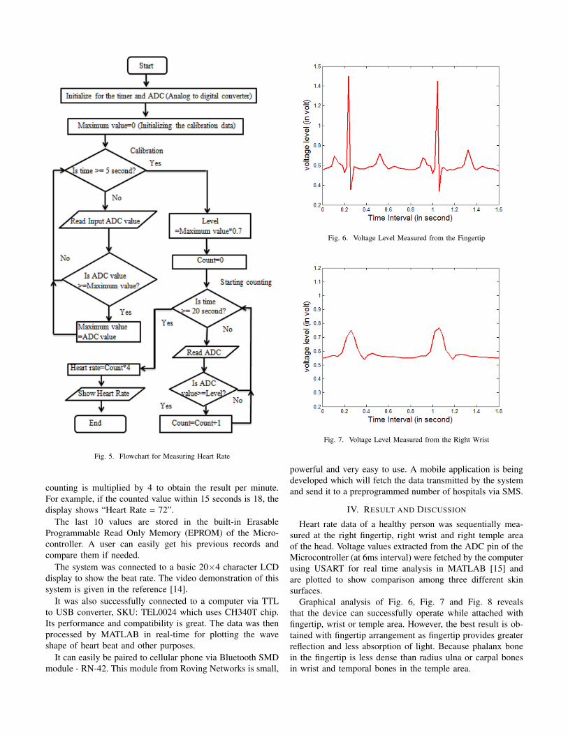
Fig. 5. Flowchart for Measuring Heart Rate
counting is multiplied by 4 to obtain the result per minute.For example, if the counted value within 15 seconds is 18, thedisplay shows “Heart Rate = 72”.
The last 10 values are stored in the built-in ErasableProgrammable Read Only Memory (EPROM) of the Micro-controller. A user can easily get his previous records andcompare them if needed.
The system was connected to a basic 20×4 character LCDdisplay to show the beat rate. The video demonstration of thissystem is given in the reference [14].
It was also successfully connected to a computer via TTLto USB converter, SKU: TEL0024 which uses CH340T chip.Its performance and compatibility is great. The data was thenprocessed by MATLAB in real-time for plotting the waveshape of heart beat and other purposes.
It can easily be paired to cellular phone via Bluetooth SMDmodule - RN-42. This module from Roving Networks is small,
Fig. 6. Voltage Level Measured from the Fingertip
Fig. 7. Voltage Level Measured from the Right Wrist
powerful and very easy to use. A mobile application is beingdeveloped which will fetch the data transmitted by the systemand send it to a preprogrammed number of hospitals via SMS.
IV. RESULT AND DISCUSSION
Heart rate data of a healthy person was sequentially mea-sured at the right fingertip, right wrist and right temple areaof the head. Voltage values extracted from the ADC pin of theMicrocontroller (at 6ms interval) were fetched by the computerusing USART for real time analysis in MATLAB [15] andare plotted to show comparison among three different skinsurfaces.
Graphical analysis of Fig. 6, Fig. 7 and Fig. 8 revealsthat the device can successfully operate while attached withfingertip, wrist or temple area. However, the best result is ob-tained with fingertip arrangement as fingertip provides greaterreflection and less absorption of light. Because phalanx bonein the fingertip is less dense than radius ulna or carpal bonesin wrist and temporal bones in the temple area.
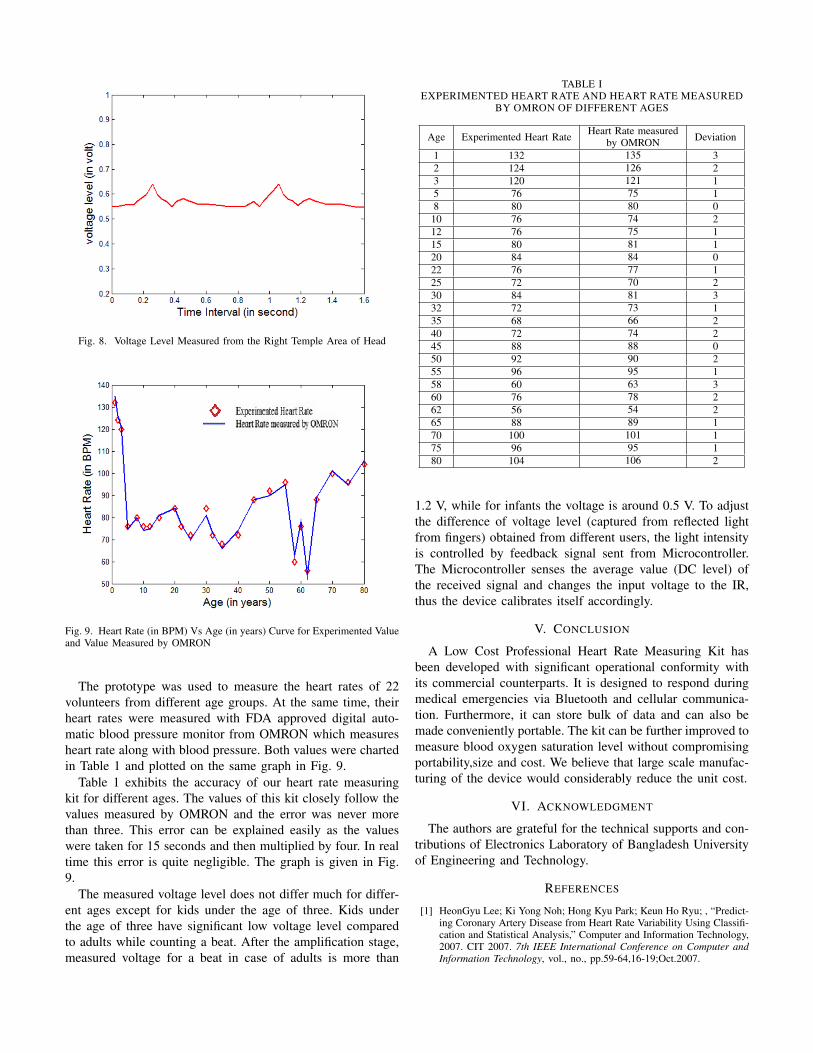
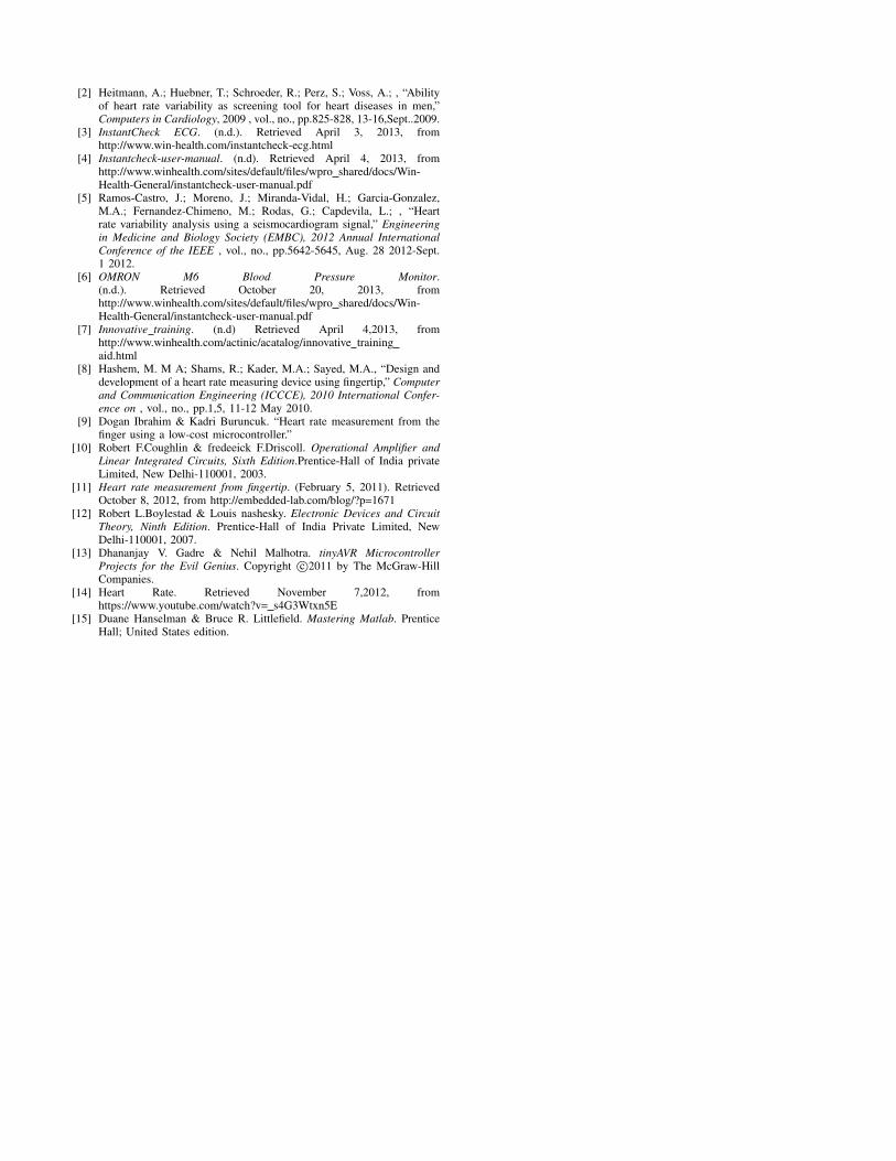
Fig. 8. Voltage Level Measured from the Right Temple Area of Head
Fig. 9. Heart Rate (in BPM) Vs Age (in years) Curve for Experimented Valueand Value Measured by OMRON
The prototype was used to measure the heart rates of 22volunteers from different age groups. At the same time, theirheart rates were measured with FDA approved digital auto-matic blood pressure monitor from OMRON which measuresheart rate along with blood pressure. Both values were chartedin Table 1 and plotted on the same graph in Fig. 9.
Table 1 exhibits the accuracy of our heart rate measuringkit for different ages. The values of this kit closely follow thevalues measured by OMRON and the error was never morethan three. This error can be explained easily as the valueswere taken for 15 seconds and then multiplied by four. In realtime this error is quite negligible. The graph is given in Fig.9.
The measured voltage level does not differ much for differ-ent ages except for kids under the age of three. Kids underthe age of three have significant low voltage level comparedto adults while counting a beat. After the amplification stage,measured voltage for a beat in case of adults is more than
TABLE IEXPERIMENTED HEART RATE AND HEART RATE MEASURED
BY OMRON OF DIFFERENT AGES
Age Experimented Heart Rate Heart Rate measuredby OMRON Deviation
1 132 135 32 124 126 23 120 121 15 76 75 18 80 80 0
10 76 74 212 76 75 115 80 81 120 84 84 022 76 77 125 72 70 230 84 81 332 72 73 135 68 66 240 72 74 245 88 88 050 92 90 255 96 95 158 60 63 360 76 78 262 56 54 265 88 89 170 100 101 175 96 95 180 104 106 2
1.2 V, while for infants the voltage is around 0.5 V. To adjustthe difference of voltage level (captured from reflected lightfrom fingers) obtained from different users, the light intensityis controlled by feedback signal sent from Microcontroller.The Microcontroller senses the average value (DC level) ofthe received signal and changes the input voltage to the IR,thus the device calibrates itself accordingly.
V. CONCLUSION
A Low Cost Professional Heart Rate Measuring Kit hasbeen developed with significant operational conformity withits commercial counterparts. It is designed to respond duringmedical emergencies via Bluetooth and cellular communica-tion. Furthermore, it can store bulk of data and can also bemade conveniently portable. The kit can be further improved tomeasure blood oxygen saturation level without compromisingportability,size and cost. We believe that large scale manufac-turing of the device would considerably reduce the unit cost.
VI. ACKNOWLEDGMENT
The authors are grateful for the technical supports and con-tributions of Electronics Laboratory of Bangladesh Universityof Engineering and Technology.
REFERENCES
[1] HeonGyu Lee; Ki Yong Noh; Hong Kyu Park; Keun Ho Ryu; , “Predict-ing Coronary Artery Disease from Heart Rate Variability Using Classifi-cation and Statistical Analysis,” Computer and Information Technology,2007. CIT 2007. 7th IEEE International Conference on Computer andInformation Technology, vol., no., pp.59-64,16-19;Oct.2007.
[2] Heitmann, A.; Huebner, T.; Schroeder, R.; Perz, S.; Voss, A.; , “Abilityof heart rate variability as screening tool for heart diseases in men,”Computers in Cardiology, 2009 , vol., no., pp.825-828, 13-16,Sept..2009.
[3] InstantCheck ECG. (n.d.). Retrieved April 3, 2013, fromhttp://www.win-health.com/instantcheck-ecg.html
[4] Instantcheck-user-manual. (n.d). Retrieved April 4, 2013, fromhttp://www.winhealth.com/sites/default/files/wpro shared/docs/Win-Health-General/instantcheck-user-manual.pdf
[5] Ramos-Castro, J.; Moreno, J.; Miranda-Vidal, H.; Garcia-Gonzalez,M.A.; Fernandez-Chimeno, M.; Rodas, G.; Capdevila, L.; , “Heartrate variability analysis using a seismocardiogram signal,” Engineeringin Medicine and Biology Society (EMBC), 2012 Annual InternationalConference of the IEEE , vol., no., pp.5642-5645, Aug. 28 2012-Sept.1 2012.
[6] OMRON M6 Blood Pressure Monitor.(n.d.). Retrieved October 20, 2013, fromhttp://www.winhealth.com/sites/default/files/wpro shared/docs/Win-Health-General/instantcheck-user-manual.pdf
[7] Innovative training. (n.d) Retrieved April 4,2013, fromhttp://www.winhealth.com/actinic/acatalog/innovative trainingaid.html
[8] Hashem, M. M A; Shams, R.; Kader, M.A.; Sayed, M.A., “Design anddevelopment of a heart rate measuring device using fingertip,” Computerand Communication Engineering (ICCCE), 2010 International Confer-ence on , vol., no., pp.1,5, 11-12 May 2010.
[9] Dogan Ibrahim & Kadri Buruncuk. “Heart rate measurement from thefinger using a low-cost microcontroller.”
[10] Robert F.Coughlin & fredeeick F.Driscoll. Operational Amplifier andLinear Integrated Circuits, Sixth Edition.Prentice-Hall of India privateLimited, New Delhi-110001, 2003.
[11] Heart rate measurement from fingertip. (February 5, 2011). RetrievedOctober 8, 2012, from http://embedded-lab.com/blog/?p=1671
[12] Robert L.Boylestad & Louis nashesky. Electronic Devices and CircuitTheory, Ninth Edition. Prentice-Hall of India Private Limited, NewDelhi-110001, 2007.
[13] Dhananjay V. Gadre & Nehil Malhotra. tinyAVR MicrocontrollerProjects for the Evil Genius. Copyright c©2011 by The McGraw-HillCompanies.
[14] Heart Rate. Retrieved November 7,2012, fromhttps://www.youtube.com/watch?v= s4G3Wtxn5E
[15] Duane Hanselman & Bruce R. Littlefield. Mastering Matlab. PrenticeHall; United States edition.