
A light-modulated scattering technique for diffraction … SCIENCE Journal of Research,...
8
RADIO SCIENCE Journal of Research, NBS j USNC- URSI Vol. 68D No.4, April 1964 A Light-Modulated Scattering Technique for Diffraction Field Measurements Ayhan M. Vural and David K. Cheng Contribution from the Elec trical Engine eri ng Department, Syr acu se Universi ty, Syracuse , N.Y. (Received October 28, 1963) . Tl :is paper des?ribes a scat te ring me thod for meas urin g mi crowave diff ractio n fi elds uSlllg light mod ul at IO n. A small photoe lectri c cell is sus pended in t he fi eld as a scat terer u pon whi ch l ight p ulses shine at an au di o r ate. Only the si O"nal scattered back by the terer is mo d ulated. A co herent d etecto r is used whi ch has ban outp ut vol tage proport ional to the square of t he ta ngent ial component of t h e fi eld un der measure ment. Since t his met hod dis penses "' i th all elect rical co.nnections to the s catt erer, circ ui t comp lications and s ourc es of error due to conn ectIOn dis turba nce and s catterer moveme nt arc eli minat ed. Hitherto unavai lable extensive data for t he ncar-zone diffraction fi elds of finite cones are prese nted. 1. Introduct ion In the st udy of the diffra ction or electromagnet ic waves from ob stacl es of complex shapes, an exact anal yt ical ap proach is usually not possible and ap- proxim ate m athem at ical solutions are generally re- mote from act ual physical co ndi t io ns. In these in stances, experimen tal r es ul ts ob tain ed wi th the aid of car ef ul ly d esigned ap parat us arc of gr eat imp ortance. The conventional probing ar ra ngem ent wiLh a trailing transmiss io n lin e fo r m easurin g diffr act ion fi elds tends to distort the fi elds under measurement and make experimen tal d ata less reli abl e. This is particul arly serious in ph ase meas ur emen ts becau e of the unavoidable fl exin g in the tra nsmission line as the pr ob e is moved around in the fi eld . To overcome the difficulties involved in t hi s arr angemen t, a scat- te ring techniq ue was in troduced for th e meas ur em en t of electric fi eld di stribu tion s [Ju stice and Rumsey, 1955]. Th e principle of this m et hod is to rel ate the d etected signal sca ttered back from a very short, thin, straight wire to th e squ are of the componen t of the electri c fi eld along th e wir e. Although t hi s system e liminat es th e transmi ssion line connections, requi rements of ex tr eme frequ en cy stability and high t uning acc ur acy limit the usefulness of the system from a pra ctical point of view. Th e modul ate d sca tt erin g t echniqu e [Richmond, 1955b] is an extension of the sca tt ering technique which is d esigned to relax th e tuning a nd stab ili ty re quirements and to increase the sensiti vity of the m eas ur emen ts by simply coding the scattered signal from a dipol e. The a mplitude modulation of the scattered fi eld, which is set up by th e indu ced cur- re n ts on the scattel' el' , m n,y be achi eved in several way s. The ori ginal and mo st common m et hod em- ploye d the non li n en,r ch aracteri st ic of a mini at ure semicon du ctor diod e fed by an audio modul n,t ing 355 signal. Th e cha nge in the imp edance of the scatter er und er the modul at in g curren t causes periodic changes in the C UITen t di stribu tion indu ced on the diode by the to tal field of interest. Th e amplit ud e of the scaLtered fi eld, which is set up by the e cur ren ts, is then modul ate d at the same rate. Thi s modul ated signal is refl ected back Lo Lhe so ur ce, separ ate d fr om the transmi tted signal by mea ns of a hybrid jun ct io n, and subjected to co herent d etection. I t m ay be shown [ Ju st ice and Rumsey, 1955] th at wh en the d iod e satis fi es cer ta in re quiremen ts, the magnit ud e of the d etecte d signal is proportional to the square of the magni tude of the ta ngential compon ent of the electric field alon g the diode and the phase is twice the ph ase of this component within an a ddi tive co n stan t. R ecell L ly Lhis sys tem was revised an d extended to the ind epen de nt measurem ent of magn et ic fi eld di s- tri bu tion [ St rait and Cheng, 1962 a and b]. Th e modul ated scat tering techniqu e employing diode scatterers t hus off ers unique f eat ur es of application . However, the electrical conn ections to the diodes carr ying modul at in g current s still requir e considera- tion. In an experiment where it is possible or re- q uired to use a condu cting ground plane, a major par t of th ese connections m ay b e lo cate d behind th e plan e. Th e di st urbances th at would be caused by th e exposed part s m ay be reduced considerabl y by using cotton thr eads coate d with a highly r es istive ma teri al such as aquad ag. In a mor e general experi- ment , th e exposed conn ections would introduce pr ac- tical difficulti es and imp air meas urem ent accur acy . Dri ed aquadag coating also has a tend en cy to crack when th e scat terer is mo ve d around . H ence a scat- terer which is electri cally isolated in the m eas ur em en t space with th e possibili ty of modul ation remains a d esirable device. Thi s paper describ es a scatterin g technique using light modul at ion, which with connectin g circuits to the sca tt erer entIrely.
Transcript of A light-modulated scattering technique for diffraction … SCIENCE Journal of Research,...
RADIO SCIENCE Journal of Research, NBSjUSNC- URSI Vol. 68D No.4, April 1964
A Light-Modulated Scattering Technique for Diffraction Field Measurements
Ayhan M. Vural and David K. Cheng
Contribution from the Electrical Engineering Department, Syracuse University, Syracuse, N.Y.
(Received October 28, 1963)
. Tl:is paper des?ribes a scat tering method for meas uring microwave diff ractio n fi elds uSlllg light modulatIO n. A small photoelectric cell is suspended in t he fi eld as a scatterer upon whi ch light p ulses shine at an audi o rate. Only t he siO"nal scattered back by t he scat~ terer is modulated. A co herent detecto r is used which has ban outp ut voltage proportional to t he square of t he tangential component of t he fi eld under meas urement. Since t his method dispenses "'ith a ll electrical co.nnections to t he scatterer, circui t complications and sources of error due to connectIOn dis turbance and scatterer movement arc eliminated. Hitherto unavailable extensive data for t he ncar-zone d iffraction fi elds of finite cones are presented.
1. Introduction
In th e study of the diffraction or electromagnetic waves from obstacles of complex shapes, an exact analytical approach is usually not possible and approxim ate mathematical solu tions are generally remo te from actual physical conditions. In these instances, experimen tal resul ts ob tained wi th th e aid of carefully designed apparatus arc of great importance.
The conven tion al probin g arrangement wi Lh a trailin g transmission line for measurin g diffraction fields tends to distor t the fields und er measuremen t and m ake experimen tal data less reli able. This is par ticularly serious in phase measuremen ts becau e of the un avoidable flexin g in the transmission line as t he probe is moved around in the field. To overcome the difficul ties involved in this arrangemen t, a scattering techniq ue was in troduced for the measuremen t of electric field distributions [Justice and Rumsey, 1955]. The principle of this method is to relate the detected signal scattered b ack from a very shor t, thin , straigh t wire to the square of the componen t of the electric field along the wire. Although this sys tem eliminates the transmission line connections, requirements of extreme frequency stability and high t uning accuracy limit the usefulness of the system from a practical point of view.
The modulated scatterin g t echnique [Richmond , 1955b] is an extension of the scattering technique which is designed to relax the tuning and stab ili ty requirements and to incr ease the sensitivity of the m easuremen ts by simply codin g the scat tered signal from a dipole. Th e amplitude modulation of the scattered field, which is se t up by the induced curren ts on the scattel'el', m n,y be achi eved in several ways. Th e original and most common method employed the nonlinen,r characteristic of a miniature semiconductor diod e fed by an audio modul n,ting
355
signal. The cha nge in the impedance of the scatterer under the modulatin g curren t causes p eriodic changes in the CUITen t distribu tion induced on the diode by the total field of in terest. The ampli tude of the scaLtered field, which is set up by the e curren ts, is t hen modulated at the same rate. This modulated signal is r eflected back Lo Lhe source, separ ated from the transmi tted signal by means of a hybr id junction, and subj ected to coheren t detection. I t m ay b e shown [Justice and Rumsey, 1955] that when the d iode satisfies cer tain requiremen ts, the m agni tude of t he detected signal is propor tional to t he squar e of the magnitude of the tangen tial component of the electri c field along the diode and the phase is twice the phase of this component within an addi tive constan t.
R ecell Lly Lhis sys tem was r evised an d extended to the independent measurem ent of magnetic field distr ibution [Strai t and Cheng, 1962 a and b]. The modulated scat terin g technique employing diode scatterers thus offers unique features of application . However, the electr ical connections to the diodes carrying modulating currents still require consideration. In an experiment where i t is possible or req uired to use a conducting ground plane, a m ajor par t of these connections may b e located b ehind the plane. The disturbances t hat would be caused by the exposed parts may be reduced considerably by using cotton threads coated with a highly resistive material such as aquadag. In a more general experiment , the exposed connections would introduce practical difficul ties and impair measurement accuracy. Dried aquadag coa ting also h as a tendency to crack when the scat ter er is moved around . H ence a scatt erer which is electrically isola ted in the m easuremen t space wi th the possibility of modulation rem ains a desirable device. This paper describ es a scattering technique using ligh t modulation , which disp~nses wi th conn ectin g circui ts to the scatterer en tIrely.

Extensive experimen tal data for near-zone electric diffraction fields around finite cones will also be presented.
2. Scattering by Light Modulation In the light-modulated scattering technique a small
photoelectric cell is used in place of the diode scatterer. Focused pulses of a light beam shine on the cell at an audio rate. The modulating mechanism relies on the periodic change in the conductivity of the photoconductive material. Since the scatterer is now completely isolated electrically, all complications and sources of error due to connection disturbance and scatterer movement are eliminated.
2.1. Principle of Operation
When an obstacle is placed in the radiation zone of a source, a total field which is the sum of the incident field and the scattered field results in the space containing the source and the obstacle. To determine the diffraction field near or at the surface of the obstacle, it is necessary to measure the phase, magnitude, and polarization of electric and magnetic fields at all desired points. When a conducting scatterer is placed at some point in the total field to be measured, a current distribution is induced on the scatterer such that the field set up by the current cancels the component of the original field tangent to its surface. If the disturbance on the original field caused by the presence of the scatterer is negligible, the current on the scatterer, and hence the backscattered signal, can be related to that component of the total field along the scatterer.
The formulation of the backscattered signal due to a small photoelectric cell is essentially the same as the diode scatterer case except for the fact that the resistance change is now a function of modulating light rather than current. With an analysis using the superposition of the backscattered signals from an open-circuited dipole and from a radiating dipole, the received signal may be expressed as [Hu , 1960)
V V K E;l~ = 0- Z + ZD' (1)
where Vo is the contribution of the open-circuited dipole, E N is the component of the electric field alon 0' the scatterer. 13 is the effective length of the scatterer , Z and ZD are the input and load impedances, respectively. K is a constant if the source excitation is kept constant. Only the second term in this equation is modulated and detected because the load impedan ce ZD is the only quan tity which is affected by the modulation. The magnitude of the detected sign al is then proportional to the square of the magnitude of E s, and the phase of the detected signal is equal to twice the phase of E s plus a constant phase shift.
2.2 . Choice of Photoconductive Material
Photoelectric transducers are devices for converting optical impulses into electrical signals.
There are tlu'ee major categories. The fiI'st class behaves primarily as variable resistors. A change in the intensity of the incident light results in a change in the conductivity of the device. These are called photoconductors. The second class produces an open-circuit voltage which is proportional to the light intensity. Finally, the response of a third class is in the form of a photocurrent proportional to the light in tensity.
The photoelectric device used in this experiment belongs to the first class, since the modulation mechanism is controlled by a variation in the resistance of the scatterer. Photoconductivity is the phenomenon of an increase in the conductivity of' a material when it is illuminated by light of sufficiently small wavelength. Although this effect is observed in almost all semiconductor materials and p-n junctions, the magnitude and the level of this variation change from material to materifll. This phenomenon is simply caused by the creation of extra free carriers upon irradiation. This can occlli' only if the absorbed photons have sufficient energy, i.e., hi/2.Eo where E o is the energy gap between the conduction and valence bands, h is the Planck's constan t, andf is the frequency.
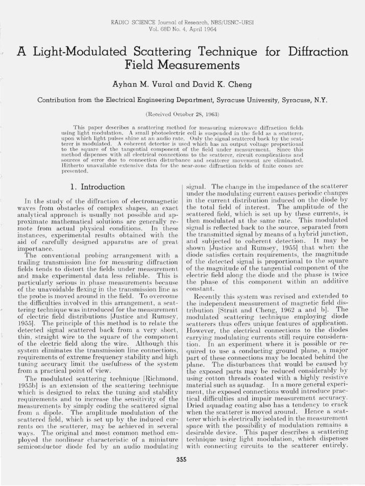
An extensive study of semiconductor crystals, films, and p-n junctions has been made to determine the characteristics appropriate for use as a modulated scatterer. Two considerations are of primary importance, namely, the operation of the devices as a dipole and the efficiency of modulation and detection. The first consideration relates primarily to the physical dimensions of the device: it must be sufficiently short, slender, and thin relative to the operating wavelength, and it is to be operated without the need of a bias. Efficiency of modulation and detection depends upon such fac tors as spectral response, frequency response, sensitivity, noise equivalent power and detectability, behavior at microwave frequencies, and tuning possibilities. The device should yield a maximum response at or near visible light frequencies, change it.s parameters with impinging light intensity when irradiated by microwaves, and offer wide resistance variations from "dark" to "light" conditions. Among the many different types of crystals, thin films, and p-n junctions examined, only CdSe and CdS possess suitable microwave properties. Resistance curves for commercially available photoconductive cells CL604L and CL605L are plotted in figure 1 versus light level. A scatterer made of tbin CdSe film was selected because of its low light resistance, high sensitivity, and relatively fast speed of response.
2 .3. Choice of Modulation Frequency
Frequency response is determined by the time constant of the photoconductive material, which in turn is a function of light level. It is essentially limited by the decay time that can be directly related to the recovery time of the semiconductor material. It takes a finite time for charge carriers to recombine after the excitation has been removed.
As a more practical experiment, the amplitude of
356
V>
E .c 0
c
~ c
~ ·in ., 0:
F IGURE 1.
6 10
105
4 10
I
3 edSe 10
2 10 ~ ____ ~ ____ ~ ______ ~ ____ -L~
. 01 .1 10 100 Light level in foo t candles
R esistance oj CdS and CdSe scatteTeTS as junction oj light level.
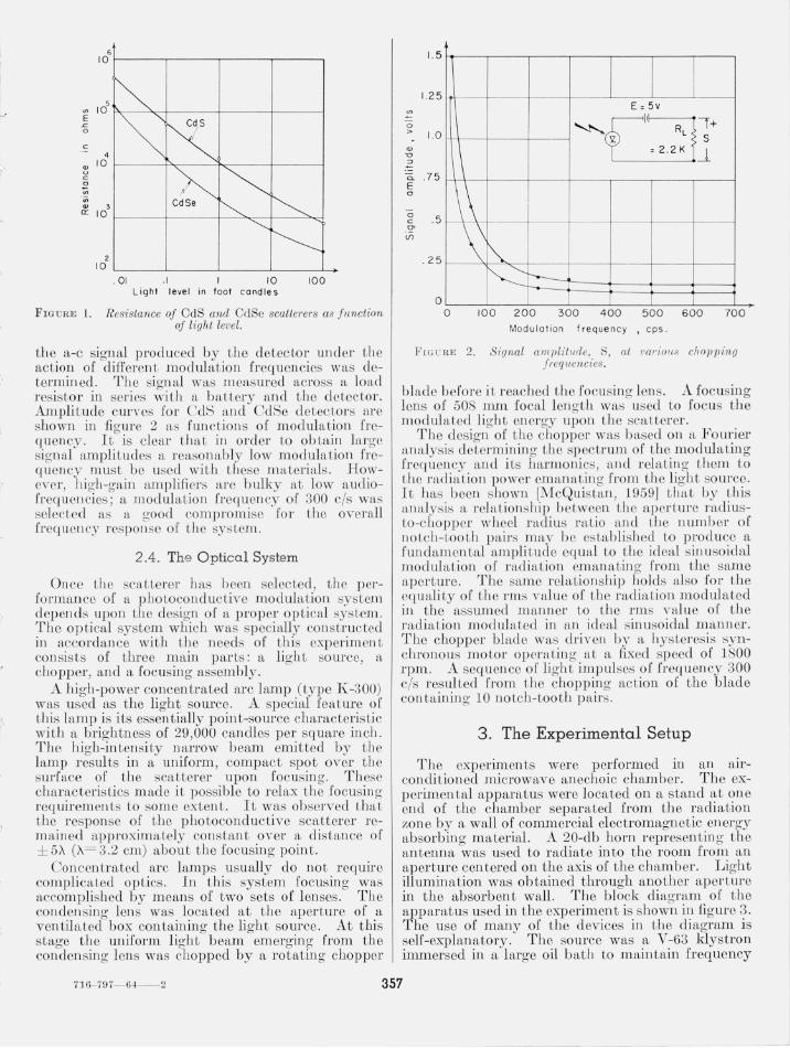
the a-c signal produced by the detector under the action of difFeren t modulation frequen cies ,vas determined. Th e signal was measured across a load resistor in seri es with a b aLtery and the detector. Ampli tude cunes [or CdS and CdSe detecLors arc shown in figure 2 a fun cLions of modulation frequell CY. It is clear Lhat ill order to obtain large signaJ ampli tudes a reaso nably low modul aLion [1'0-qUCJlCy must be used wi th these materiaJs. However, high-gain amplifiers are bulky at low aud iofrequencies; a modulaLio n frequency of 300 cis was selected as a good compJ'omise 1'01' the overall freq uency response of the system.
2 .4 . The Optical System
Once the scatLeJ'er has been selected, the p erformance of (1, phoLoconductive modulation sys tem depends upon the design of a proper optical sysLem . The op tical system which was specially constructed in accordance wi th the n eeds of this experimen t consists of three main par ts: a light source, a, chopper , and a focusing assembly.
A high-power concentrated arc lamp (type K-300) was used as the light source. A special feature of tbis la.mp is its essentially point-source characteris Lic with a brightness of 29,000 candles per square inch . The high-intensity narrow beam emitted by the lamp results in a uniform, compact spot over the surface of the scatterer upon focusin g. These characteris tics made it possible to relax the focusin o'
requirements to some extent, It was observed Llu;1 tbe response of the pho toconductive scatterer remained approximately COl1s ta.nt over a distance of ± 5A (A= 3.2 cm) about the fo cusing point.
Con cen Lra ted arc lamps usually do not require complica ted optics, In this sys tem focusing was accomplished by means of two sets of lenses. The condensing lens was located at the aperture of a ventilated box containing the light source. At this stage the uniform light b eam emerging from the condensing lens was chopped by a rotating chopper
u>
0 >
Q)
" ::J
a. E a
"0 c
'" tf)
1. 5
1.25
1.0
.75
.5
.25
o o
E = 5v
~" RL
\ 'l S
= 2.2K -.l
\\ \ ~ ~ r--
100 200 300 400 500 600 700 Modulation f requen cy , cps .
Fl C U RB 2. Signal amplitude, S, at variolls ciloP7Jing frequencies .
blade before it reached t he fo cusin g lens. A focusing lens of 508 mm focal length wa,s used to focus the modulated light energy upon the scatterer.
Th e design of the cltOpper was based on a Fourier a l1 alysis determinin g the spectrum of Lhe modulating freguency and iLs harmonics, and relaLin g them to the radiation power emanat in g from the l ight source. It l iaS been shown [:iV[cQuistan , 1959] that by Lhis analys is a l'clil.tionship beLween the aperture l'au iuslo-c/tOpper wheel radius ratio and Lhe uumb er of noLch-Looth pairs may b e established to produce a fundamenLal ampli tud e equal to the ideal sil1uso id al modulation of l"adi<l,tion emanating from the same aper ture. Th e same relaLionship holds also for the equali ty of the rms value of the radiaLion modulated in the assumed mann er to tbe rms value of the radiation moduln, tcd in a ll id eal sinusoid al mal1ner. The chopper blade was driven by a hysteresis synchronous mo tor opemtin g at a fixed speed o[ 1800 rpm. A sequence of lighL impulses of freq uency 300 cis resul ted from the choppin g acLion of the blade con tainin g 10 no tch-tooth pairs.
3. The Experimental Setup
The experiments were performed in an alrconditioned microwave anechoic chamber. The experimental apparatus were located on a stand at one end of the chamber separ ated from the radiation zone by a wall of commercial electromagnetic energy absorbing material. A 20-db horn representin g the antenna was used to radiate into the room from an aperture cen tered on the axis of the chamber , Light illumination was obtained through ano ther aperture in the absorbent wall. The block diagram of the apparatus used in the experiment is shown in [lgure 3. The use of many of the devices in the diagram is self-explanatory . The source was a V-63 klystron immersed in a large oil bath to maintain frequency
716- 797--64----2 357

Phase shifter
I solator
Load
I solator
Selective Amplifi er
Scatterer "'- Tuner ~ Antenna
Xmt- rcv
Attenuator
. . Ref. arm Attenua- Hybrld Junctlon tor
Load equency ~------~-------Meter
Power Meter Nylon Thread
Supports
'--__ ----'R:..:.e:.:f:.:ec::.r ..;:..enc e Arm
Power Suppl y
Sour ce
20- db Coupl er
FIGURE 3. Block diagram oj experimental set-up.
stability. The frequency of operation was 9375 Mc/s (/..= 3.2 cm). System performance was monitored by the frequency meter and the power meter.
The source establishes an electromagnetic field through the antenna. The photoconductive scatterer modulated periodically by the light source creates a modulated scattered field which is received by the same an tenna. Isolation between the transmitted and the back-scattered signals is accomplished by tIle properties of a transmi t-receive hybrid j unction . If a perfect match is obtained between the antenna and the load, the transmitted power is divided evenly between them and none enters the receiver. The r eceived power is directed to a detector hybrid jun ction by the same property. This received signal and a reference signal taken from the reference arm of a 20-db coupler are then divided between the two collinear arms (in phase in one arm and out of phase in the other arm) of the detector hybrid junction in which the barretters are mounted. Some unmodulated error signal resulting from slight detuning of the transmit-receive hybrid junction will also be transferred to the detector junction. These signals are processed in a receiving system consisting
358
of a coherent detector, a selective amplifier of 4 cis bandwidth about 300 cis, and an output meter.
The output of the coherent detector can be shown to be [Richmond, 1955a]
(2)
where Eo L.(3 is the reference signal, E s L.'Y is the component of E alon g the scatterer, and k is a proportionality constant.. The performan ce of the system depends on a good tWling procedure. This procedure has been explained in detail by S trait and Chen g [1962a and b] previously. When t he phase shifter in the rererence arm is adjusted so that the reading of the output meter is a maximum ((3 = 2'Y), then
(3)
Sillce k and Eo are constants, both the amplitude and the phase of E s can be determined.
Tb e scattererwas supported by thin nylon tln'eads attached to a large frame. The disturban ce of the field due to the nonconductin g supporting threads was completely negligible. The motion of the scat-

terer through tbe field was accomplisbed by a string and pulleys arrangement attached to the frame. Since the signal scattered back hom the fram e is Jl0t modulated, it does not affect the accmacy of the experiment. However, the frame was constructed as large as possible in accordance with the dimensions of the room and was covered with absorben t material to minimize reHection.
To check the validity of the system, preliminary experiments were performed to map the diffraction field of a circular apertme in a conducting plane for which exact solutions exist and accurate experimental res ults are available [Strait and Cheng, 1962a and bJ. In all cases, data obtained by using the light-modulated scattering technique checked very closely with previously published results [Vural, 1962].
4. Diffraction Fields of Finite Cones
Scatterin g of electromagnetic and acoustic waves by cones has been invesLigaLed in the literature. However, most of the previous effOl-Ls 011 this subject were con cen Lrated on the evalu ation of tbe backscattered field s in relation to Lhe 1'1tdal' cross section s of semi-infiniLe cones. Even in Lhi simplifted problem , serious difficulti es arose in evaluating numerical results from tbe solutions whi ch were in terms of infinite series or integrals. 'When the wavelen gth is very short in comparison with the dimensions of the obstacle, ordinary geom etric optics m eLh ods can be generalized to include diffraction nws. Keller [1960] appli ed the geonl eLrical theory of diffraction Lo the problem of plan e-wave b f1ck-scallerin g from a fini te cone. As Jar as the presen t auLhors can determine, neither theoretical cttlculaLions 1101' experim en tal data are aVDilable I' or n ear-zon e diirraction fields due Lo flllite cones. The light-modulat ed sC11ttering technique discussed above was adapted Lo measurin g th e diffraction fields of fmite conducting cones: it was 11 task which could not be done with nccul'~1CY usin g the more conven tional m ethods.
~Ieasurem ents hnve been made with tll]'ee right circular alum inum cones (hnlf apex angles 20°, 4c5°, nlld 67 °) and with a flat aluminum disk (balI apex allgle 90°) of 5-wavelength diameter. The cones have different heights, but all have a base diameter 01' 5A. Because of space limitation , only selected e1aLa, 1'01' the 45° cone are presented here. Measurements with the disk checked very well with the published curves of Ehrlich et a1. [1955] . A comparison of results is shown in figme 4.
The tip of the cone is chosen as the origin of the coordin ate system, and the 11 egative z-axis coincides with Lhe axis of symmetry. The incident plane Wlwe is polarized in the y-direction . Figure 5 is a plot of t he square of the normalized y-component of the electric field , IE y/E !1 2, as a function of the disb1J1 co from th e tip of the con e along the COIl e axis. Distinct sLandin g waves exist there. Figw'e 6 shows th e disLribution of IEulE il2 at various values of z in I he principal H-plane (y= O). For n egaLive values of z, the readin gs start from points very close 1,0 , but
2 IE, / E ; I
2
'V Edge
I o ~ 5, z ~·J/2'
~ .......--.. ~ 0
xiX 3 4 5 6
__ Measured by Ehrl ich, Silver and Held
o 0 0 Measure d by photoconductive modulation system
FIGURE 4. A comparison of the l'esltits obtained f01 the nearfield distl'ibution of a circular disk.
2~---.-----. ____ ~ ____ ~ ____ ~ __ --,
OL-__ ~ ____ ~ ____ -L ____ -L ____ ~ ____ ~~Z /A
o 2 3 4 5 6
FIG URE 5. IE, /Ei 12 as a function of distance from cone tip fol' 45° cone.
not quite on , th e cone s urf~LCe because of the finite dim ensions of the phoLoconduct ive scatterer.
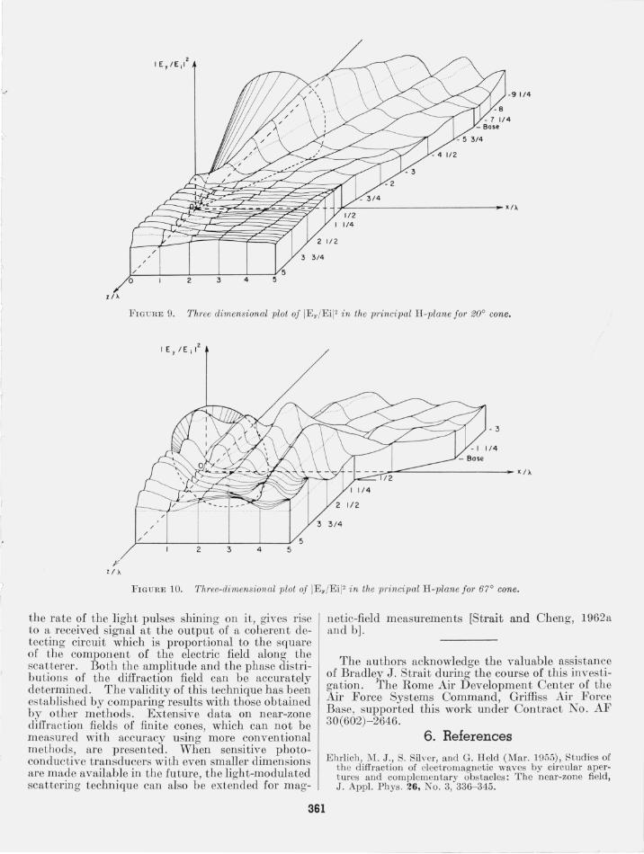
Fields at points off th o principal II-plan e were also measuTed. Sample CLll'ves in planes containing the tip (z=0) and the base (z= -2)~A) of Lhe 45° cone are shown in fi gure 7 I'or y = H~A , 2 ?f ).. , and 3%A. A composite, three-dimensional contour plot 1'01' the distribuLion of IE y/E ;12 in the principal EJplnne for the 45° cone is given in figme 8, which affords a better perspective. In order to show the difference ill Lhe distribution of near-zone diffraction fields in the neighborhood of finite cones of different apex angles, the corresponding con tom plots of IE y/E iI 2 [or the 20° and 67° cones are also given in figures 9 and 10, respectively. The cross-polarized component of the diffraction field , E x/E" was also measured. In all cases, it was much smaller than E/yE ;.
5. Conclusions
A new method for measuring microwave diffraction fields has been described. It employs a small photoconductive scatterer in a light-modulated sca ttering technique which dispenses with connecting circuits to the scatterer en tirely, thus minimizing the distmbance on the field under measmement. The varying resistance of the scatterer, changing at
359

""'E±E""I""'I I o 2 34567 8
XI )'
o 3 4 6 7 8
(e) z, o ( tip)
I ... ~ ~ ~ "'....-r i'----
Cone T1,P x l)' -/ o o 4 6 8
~ ! A ( d ) z , - 3 / 4),
ur~oc:r -\ V\. V\ k/ "-Cone j 5 XI), o
o 4 6 7 8
1 _
()
F I GURE 6. Distribution of IEy /Ei I2 at various values of z in princi pal H -plane (y = O) f or 45° cone.
z /X
o o
o
o
iVEd (0) l ' 1 1/ 4).
-1'\ i,P... .... '-0'
(b) l' 2 1/ 2 ),
.... lr----"-' "+'
(e) 1, 33/ 4 )'
- t--'" -..... ~ 3 4
Con e t i p (Z ' 01
X I)'
X I )'
x/
E/ Ed (d ) 1 ' I 1/4 ).
,re k ~
V ..... V I--" o k/
2 . ~ 3.S 45 5.5 6.5 7.5 8.5
(e) 1 · 2 1/2 \
P V ........ o xl)'
2.5 3.5 4.5 5.5 6 .5 1.5 8.5
(f) Y '33/ 4 ),
o 1""- i'-~ V r--- , fA
2.5 3.5 4 . .5 5.5 6.5 7.5 8.5
Cone base (z = · 2 1/ 2 A )
FIG URE 7. Dist1-ibution of IEy /EiI2 in planes parallel to principal H -plane (45° cone).
- 4 1/2
1/4
~~ ____________________ ~ x / X
F IG U RE 8. Three dimensional plot of IEy /Ei I2 in principal H -plane for 45° cone.
360
o
l /~
FIGURE 9. Three dimensional plot of IE y /Ei I2 in the principal H-plane for ~WO cone.
/ /
;:/'--__ -'-__ ----'-____ -L-__ -L __ -Y 5 2 3 4 5
- 3
~~~--------------~'/A
3 3 / 4
FIGURE 10. Thl'ee-dimensional plot of IE y /Ei I2 in the principal H-plane for 67° cone.
the rate ?f the. light pulses shining on it, gives rise to a. receIved slgnal at the output of a coherent det~ctmg circuit which is proportional to the square of the component of the electric field along the sca~terer. Both the amplitude and the phase distributlOn s. of the diffraction field can be accurately deterr~llned. The validity of this technique has been establIshed by comparing results with those obtained by other methods. Extensive data on near-zone diffraction fields of finite cones, which can not be measured with accuracy using more conventional method~, are presented. When sensitive photoconductIve transducers with even smaller dimension s are ma~e availa~le in the future, the light-modulated scattermg techmque can also be extended for mag-
361
n etic-field measurements [Strait and Oheng, 1962a and b).
The authors acknowledge the valuable assistance of Bradley J. Strait during the course of this investig~tion. The Rome Air Development Oenter of the Au' Force Systems Oommand Griffiss Ail' Force Base, supported this work und~r Oontract No. AF 30(602)- 2646.
6. References
Ehrlich ,. r,;[. J .. , S. Silver, and G. H eld (Mar. 1955), Studies of t h e diffract IOn of electromagnetic waves by circular apert ures and complementary obstacles: The near-zone field, J. App!. Phys . 26, No.3, 336- 345.

Hu, M. K . (May 1960), On measurements of E and H field distribu t ions by using modulated scattering methods, IRE Trans. M icrowave Theory T ech. MTT- 8, 295- 300.
Justice, R, and V. H. Rumsey (Oct. 1955), Measurement of electri c fi eld d istributions, IRE Trans . Antennas Propagation AP- 3, No.4 , 177- 180.
Keller, J . B. (Mar. 1960), Backscattering from a finite co ne, IRE Trans . An t. Prop. AP- 8, No.2, 175- 182.
McQuistan, R B . (J an . 1959), On radiation modulation , J . Op t. Soc . Am. 49, No.1, 70- 74.
Richmond , J. H . (April 1955a), Measuremen t of t ime-quadrature components of microwave signals, IRE Trans. Microwave Theory Tech. MTT- 3, No.3, 13- 15.
Richmond , J . H. (July 1955b), A modula ted scatteri ng technique for m easurement of field distribu tions, IRE Trans. Microwave Theory T ech. MTT- 3, No.4, 13- 15.
Stra it, B. J. , and D . K. Cheng (Jan. 1962a), Microwave magnetic-field measurements by a modulated scattering tec hnique, Proc. l EE (England) 109, P t . B, 33- 40.
Strai t, B. J ., and D. K. Cheng (Sep t. 1962b), Measurement of microwave magnetic diffraction fields, IRE Trans. Ant. Prop. AP- 10, No.5, 643- 645.
Vural, A. M. (Dec. 1962), Measurement of diffraction fi elds of fini te cones by a scattering technique using ligh t modulation, M.E.E. Thesis (Syracuse Univ., Syracuse, New York) .
Additional References
Iizuka, K. (Oct. 1963) , Photoconductive probe for measuring electromagnetic fi elds, Proc. l EE 110, No. 10, 1747- 1754.
Vural, A. M. , D . K. Cheng, and B. J . Strait (Mar. 1963), Measurement of diffraction fi elds of fini te cones by a scatterin g technique using ligh t modulation , IRE Trans. Antennas Propagat ion AP- 11, No.2, 200- 201.
(P aper 68D4- 353)
1


