
A KEY-POSE BASED REPRESENTATION FOR HUMAN ACTION · PDF filea key-pose based representation...
57
A KEY-POSE BASED REPRESENTATION FOR HUMAN ACTION RECOGNITION a thesis submitted to the department of computer engineering and the graduate school of engineering and science of bilkent university in partial fulfillment of the requirements for the degree of master of science By Mehmet Can Kurt July, 2011
Transcript of A KEY-POSE BASED REPRESENTATION FOR HUMAN ACTION · PDF filea key-pose based representation...

A KEY-POSE BASED REPRESENTATIONFOR HUMAN ACTION RECOGNITION
a thesis
submitted to the department of computer engineering
and the graduate school of engineering and science
of bilkent university
in partial fulfillment of the requirements
for the degree of
master of science
By
Mehmet Can Kurt
July, 2011

I certify that I have read this thesis and that in my opinion it is fully adequate,
in scope and in quality, as a thesis for the degree of Master of Science.
Asst. Prof. Dr. Pınar Duygulu(Advisor)
I certify that I have read this thesis and that in my opinion it is fully adequate,
in scope and in quality, as a thesis for the degree of Master of Science.
Asst. Prof. Dr. Selim Aksoy
I certify that I have read this thesis and that in my opinion it is fully adequate,
in scope and in quality, as a thesis for the degree of Master of Science.
Prof. Dr. Aydın Alatan
Approved for the Graduate School of Engineering and
Science:
Prof. Dr. Levent OnuralDirector of the Graduate School of Engineering and Science
ii

ABSTRACT
A KEY-POSE BASED REPRESENTATION FORHUMAN ACTION RECOGNITION
Mehmet Can Kurt
M.S. in Computer Engineering
Supervisor: Asst. Prof. Dr. Pınar Duygulu
July, 2011
This thesis utilizes a key-pose based representation to recognize human ac-
tions in videos. We believe that the pose of the human figure is a powerful source
for describing the nature of the ongoing action in a frame. Each action can be
represented by a unique set of frames that include all the possible spatial config-
urations of the human body parts throughout the time the action is performed.
Such set of frames for each action referred as “key poses” uniquely distinguishes
that action from the rest. For extracting “key poses”, we define a similarity value
between the poses in a pair of frames by using the lines forming the human figure
along with a shape matching method. By the help of a clustering algorithm, we
group the similar frames of each action into a number of clusters and use the
centroids as “key poses” for that action. Moreover, in order to utilize the motion
information present in the action, we include simple line displacement vectors for
each frame in the “key poses” selection process. Experiments on Weizmann and
KTH datasets show the effectiveness of our key-pose based approach in repre-
senting and recognizing human actions.
Keywords: Human motion, action recognition, key-pose, pose similarity, pose
matching.
iii
OZET
INSAN HAREKETLERININ TANINMASI ICINANAHTAR KARE TABANLI BIR POZ TEMSILI
Mehmet Can Kurt
Bilgisayar Muhendisligi, Yuksek Lisans
Tez Yoneticisi: Yrd. Doc. Dr. Pınar Duygulu
Temmuz, 2011
Bu tezde, videolardaki insan eylemlerini tanımak icin anahtar kareye dayalı
bir poz temsilinden faydalanılmaktadır. Insan figurunun olusturdugu pozun,
bir kare icerisinde devam eden eylemi tanımlamak icin cok guclu bir kaynak
oldugunu dusunuyoruz. Her eylem, o eylemin gerceklestigi sure icerisinde in-
san vucudunun parcalarının olusturdugu butun uzamsal duzenlesimleri iceren bir
kare grubuyla temsil edilebilir. “Anahtar Kare” olarak adlandırdıgımız bu kare
grubu bir eylemi digerlerinden ayırt eder. “Anahtar Kare”leri secmek icin, insan
figurunu olusturan cizgilerle beraber bir sekil esleme metodu kullanarak, ver-
ilen iki kare uzerindeki pozların arasında bir benzerlik degeri tanımlıyoruz. Bir
kumeleme algoritması kullanarak, her eylemin benzer karelerini belirli bir sayıda
kumede grupluyor ve bu grupların agırlık merkezlerini “Anahtar Kare” olarak kul-
lanıyoruz. Dahası, insan figurunu olusturan cizgilerin hareketlerini video dizisi
boyunca takip ederek, eylem icerisindeki devinim bilgisinden de faydalanıyoruz.
Weizmann ve KTH verisetleri uzerinde elde ettigimiz sonuclar, “Anahtar Kare”
bazlı yaklasımımızın insan hareketlerini temsil etme ve tanımadaki etkinligini
gostermektedir.
Anahtar sozcukler : Insan hareketi, eylem tanıma, anahtar kare, poz benzerligi,
poz esleme.
iv

To my grandmother Aysel Tutuncu . . .
v

Acknowledgement
First and foremost, I would like to thank my supervisor Asst. Prof. Dr. Pınar
Duygulu for her encouragement, guidance and kindness. She supported me in the
best possible way throughout my studies.
I would also like to thank the members of my thesis committee Asst. Prof.
Dr. Selim Aksoy and Prof. Dr. Aydın Alatan for reviewing my thesis and making
valuable comments.
I would like to send my best wishes to my friend Sermetcan Baysal for sharing
his ideas with me and for being such a great partner throughout my studies.
I thank my lovely wife, Pelin Damcı, for her amazing support during my
seven years at Bilkent University. I am grateful to Gulcin Damcı, Nezih Damcı
and Ayten Ozbek for their incredible help and their love. I also would like to
make a special reference to my best friend Ilker Tufan for always being there for
me.
Last but not least, I feel very lucky to have such a great mother and father,
Gulay Kurt and Serdar Kurt, who have raised me with love and have supported
me during my entire life. Without them, I couldn’t be the person that I’m today.
vi

Contents
1 Introduction 1
1.1 Motivation . . . . . . . . . . . . . . . . . . . . . . . . . . . . . . . 1
1.2 Overview and Contributions . . . . . . . . . . . . . . . . . . . . . 3
1.3 Organization of the Thesis . . . . . . . . . . . . . . . . . . . . . . 4
2 Related Work 6
2.1 Review of Previous Studies . . . . . . . . . . . . . . . . . . . . . . 6
2.2 Discussion of Related Studies . . . . . . . . . . . . . . . . . . . . 9
3 Our Approach 10
3.1 Pose Extraction and Representation . . . . . . . . . . . . . . . . . 10
3.1.1 Line Extraction . . . . . . . . . . . . . . . . . . . . . . . . 10
3.1.2 Shape Context Descriptor . . . . . . . . . . . . . . . . . . 11
3.1.3 Point Generation . . . . . . . . . . . . . . . . . . . . . . . 14
3.2 Finding Similarity between Two Poses . . . . . . . . . . . . . . . 14
3.2.1 Matching Methods . . . . . . . . . . . . . . . . . . . . . . 15
vii

CONTENTS viii
3.2.2 Utilizing Other Visual Clues . . . . . . . . . . . . . . . . . 18
3.2.3 Spatial Binning . . . . . . . . . . . . . . . . . . . . . . . . 18
3.3 Finding Key Frames . . . . . . . . . . . . . . . . . . . . . . . . . 20
3.4 Utilizing Motion Information . . . . . . . . . . . . . . . . . . . . . 21
3.5 Recognizing Actions . . . . . . . . . . . . . . . . . . . . . . . . . 24
3.5.1 Majority Voting . . . . . . . . . . . . . . . . . . . . . . . . 24
3.5.2 Sum of Minimum Distances . . . . . . . . . . . . . . . . . 26
3.5.3 Dynamic Time Warping . . . . . . . . . . . . . . . . . . . 27
4 Experiments 28
4.1 Datasets . . . . . . . . . . . . . . . . . . . . . . . . . . . . . . . . 28
4.1.1 Weizmann . . . . . . . . . . . . . . . . . . . . . . . . . . . 28
4.1.2 KTH . . . . . . . . . . . . . . . . . . . . . . . . . . . . . . 29
4.2 Experimental Results . . . . . . . . . . . . . . . . . . . . . . . . . 30
4.2.1 Evaluation of Number of Key Frames . . . . . . . . . . . . 30
4.2.2 Evaluation of Spatial Binning and Tolerance . . . . . . . . 32
4.2.3 Adjusting Sampling Factor for Point Generation . . . . . . 33
4.2.4 Evaluation of Different Classification Techniques . . . . . . 34
4.2.5 Evaluation of Matching Methods . . . . . . . . . . . . . . 35
4.2.6 Utilizing Other Visual Clues . . . . . . . . . . . . . . . . . 37
4.2.7 Involving Motion Information . . . . . . . . . . . . . . . . 37

CONTENTS ix
4.3 Comparison to Related Studies . . . . . . . . . . . . . . . . . . . 41
5 Conclusion 42
5.1 Summary and Discussion . . . . . . . . . . . . . . . . . . . . . . . 42
5.2 Future Work . . . . . . . . . . . . . . . . . . . . . . . . . . . . . . 43

List of Figures
3.1 Extracted Lines in a walking sequence . . . . . . . . . . . . . . . 11
3.2 Calculating shape context of a point . . . . . . . . . . . . . . . . 12
3.3 Effect of sampling factor on generated points . . . . . . . . . . . . 13
3.4 Left-To-Right matching example on a pair of frames . . . . . . . . 16
3.5 Hungarian Method example on a pair of frames . . . . . . . . . . 17
3.6 Spatial binning of a human figure . . . . . . . . . . . . . . . . . . 19
3.7 Extracted set of key frames for some actions . . . . . . . . . . . . 21
3.8 Extraction of fw and tw vectors . . . . . . . . . . . . . . . . . . . 23
3.9 Action recognition using Majority Voting Scheme . . . . . . . . . 24
4.1 Example frames from Weizmann dataset . . . . . . . . . . . . . . 29
4.2 Example frames from KTH dataset . . . . . . . . . . . . . . . . . 30
4.3 Recognition accuracies when the number of key frames K is increased 31
4.4 Confusion matrix on Weizmann dataset when K = 20 and K = 50 32
4.5 Effect of Grid Tolerance . . . . . . . . . . . . . . . . . . . . . . . 33
x

LIST OF FIGURES xi
4.6 Effect of Sampling Factor for Point Generation . . . . . . . . . . . 34
4.7 Evaluation of Different Classification Techniques . . . . . . . . . . 35
4.8 Evaluation of Different Matching Methods . . . . . . . . . . . . . 36
4.9 Effect of Using Motion Information on Weizmann Dataset . . . . 38
4.10 Confusion Matrix for the Best Result in Figure 4.9 . . . . . . . . 39
4.11 Effect of Using Motion Information on KTH Dataset . . . . . . . 40
4.12 Confusion Matrix for the Best Result in Figure 4.11 . . . . . . . . 40

Chapter 1
Introduction
1.1 Motivation
Human Action Recognition, which is a research area listed under computer vision,
has drawn immense attention over the years. Previous research done in the field
has resulted in a large variety of applications such as automatic surveillance and
monitoring, social analysis and human-computer interaction. Along with the
improving hardware technologies, the demanding nature of these applications
keep the challenge of developing more effective and efficient systems for human
action recognition alive.
Motivated by the needs of these applications, this thesis addresses the problem
of recognizing human actions in videos automatically. However, it is well known
that building a robust system for human action recognition is not trivial due
to several reasons. First of all, finding the area of the image where the action is
performed can be quite difficult. Especially, in cases where there is a great deal of
noise in the background, spotting the human figure in its entirety is a challenging
task. Secondly, even for simple actions, the way an action is performed may show
a great variety from person to person. Moreover, the shooting conditions such
as illumination changes in the environment, scale and viewpoint variations may
cause further complications in the analysis of the ongoing actions. Considering
1

CHAPTER 1. INTRODUCTION 2
these facts, representing the actions in a robust way plays an important role in
the success of an action recognition system.
Despite the challenges for recognizing human actions explained above, the
human brain can distinguish an action from the others just by looking at a single
frame without having the need of seeing the rest of the sequence. This important
observation is a clear indication of the fact that the pose formed by the human
figure is a powerful source for describing an action. For this reason, exploiting
the pose information encoded in a frame can be an effective approach in solving
human action recognition problem. In fact, there are some previous studies [2,
3, 22], which attempt to represent the shape of a pose by using extracted human
silhouettes. However, the performance of these works may suffer in the scenes
where the quality of the extracted silhouettes are severely affected by the noise
in the background.
An alternative approach for representing the pose information in a frame is to
consider the pose of the human figure as a shape and to utilize one of the existing
shape matching techniques in the literature of human action recognition. Shape
Context Descriptor [1] introduced by Belongie et al. stands as a widely known
shape matching technique which is initially developed as an object recognition
scheme. In this thesis, we utilize Shape Context Descriptor as a tool to determine
the similarity of the poses formed by the human figure in given frames. On top
of identifying the pose differences in two actions by means of Shape Context, we
extend the fact that the human brain can distinguish an action by looking at
a single frame and we perform human action recognition by extracting a set of
frames (“key frames”) for each action.
This approach is powerful in distinguishing the actions which show significant
differences in the poses the human figure forms. However,“key frames” might not
be enough by itself to detect the differences between some actions such as walking
and running. In order to get rid of such limitations, the pose representation
might be supported by the motion information encoded in an action sequence.
Therefore, in this thesis, we also maintain the motion information of the lines
forming the human pose in each frame composing the “key frame” set.

CHAPTER 1. INTRODUCTION 3
1.2 Overview and Contributions
Our overall method consists of the following steps. Initially, we detect the lines in
each frame of an action and hold a description for each line by using k-Adjacent
Segments [8]. After applying some noise removal techniques, we come up with a
set of lines which form the human figure in each frame. Secondly, we generate
a set of uniform points from the extracted lines. By feeding these points into
Shape Context [1], we generate a descriptor vector for each point in the frame.
The generated descriptors for each point are combined into a Shape Context
matrix.
Thirdly, in order to find the similarity value between a pair of frames of
an action, we calculate the distance between the shape context descriptors of
each pair of points in the frames by means of chi-square distance. We create
a similarity matrix with the computed distance values and produce a matching
between the points of the frames with one of the two methods; Left-To-Right
Matching or Hungarian Method [14]. Based on two different strategies, Left-To-
Right matching and Hungarian Method have their own advantages which may
reveal in different cases. For a more accurate matching between the points, we
also employ a spatial constraint which prevents any two points that are located
in different regions of the frames from being matched. After creating a set of
matched points, we compute an overall similarity value between two frames by
using the individual similarity values between matched points.
As a next step, we group the similar poses of each action in a defined number
of clusters by using k-medoids clustering algorithm and we form the “key frame”
set for that action by taking the medoid of each cluster.
In order to support the “key frame” set of each action with motion informa-
tion, we detect the location of the lines forming the human figure in a key frame
in the frames that come just before and right after it. After spotting each line
both in previous and next frame, we calculate a displacement vector for that line
by taking the difference in x and y coordinates. This displacement information
reflects where the line is coming from and where it is going next. Repeating this

CHAPTER 1. INTRODUCTION 4
process for each line in the key frame, we create two displacement vectors that
we call “from where” and “to where”. This step completes the entire training
process.
For classifying a given sequence of poses, we utilize three schemes; Majority
Voting, Sum of Minimum Distance and Dynamic Time Warping. When using the
Majority Voting, we compare each frame of the test sequence to all key frames
of all actions and assign the action label of the most similar key frame to that
frame. Repeating the same procedure for the entire test sequence, we apply
Majority Voting among the assigned labels in order to make a final decision. On
the other hand, when using the Sum of Minimum Distance, we find each action’s
most similar key frame to each test frame and we accumulate those minimum
distances. Finally, the label of the action that has the minimum total distance
becomes the classification result of the tested sequence. When using the Dynamic
Time Warping (DTW), we find a correspondence between the pose order of two
sequence. Calculating a similarity value between the given test sequence and
training sequences of each action, we classify the test sequence as the action that
contains the most similar training sequence with respect to DTW distance.
We present two important contributions with this thesis. The first one is
approaching the human action recognition as a shape matching problem and
applying Shape Context, which is developed for object recognition, for recognizing
human actions. The second is representing an action with a set of frames named
as “key frames” which cover the pose information in an action sequence along
with the motion information.
1.3 Organization of the Thesis
The remainder of this thesis is organized as follows.
Chapter 2 presents a literature review in human action recognition. It de-
scribes the previous work done in the field and discusses its drawbacks.

CHAPTER 1. INTRODUCTION 5
Chapter 3 describes our approach. It explains our key-frame extraction algo-
rithm in detail and shows how actions can be classified by utilizing the extracted
key-frames.
Chapter 4 shows the experiments conducted on the state-of-the-art action
recognition datasets, discusses our results and compares them with the results of
the previous work.
Finally, Chapter 5 shows our concluding remarks and introduces possible fu-
ture research.

Chapter 2
Related Work
Human Action Recognition has received considerable attention over the last
decade. There are a large number of recent studies which approach the prob-
lem in different ways. In this chapter, we give a review of the previous work
performed in the field.
2.1 Review of Previous Studies
A large number of studies in the past extend 2D interest points used in object
recognition and apply the idea to the spatio-temporal case. In [15], by employing
a space-time extension of Harris operator, Laptev et al. detect interest points
in multiple levels of spatio-temporal scales and use them for action recognition
by employing a SVM classifier. Dollar et al. in [5] combine space-time interest
point approach with bag of words model which is often employed in information
retrieval. They represent an action by a statistical distribution of the bag of
video-words after extracting interest points by applying separate linear filters in
both spatial and temporal directions. In [17], Liu et al. give a a model in which
they quantize the extracted 3D interest points and represent a video sequence by
a bag of spatio-temporal features named as video-words. In the same work, they
discover the optimal number of video-word clusters by means of Maximization
6

CHAPTER 2. RELATED WORK 7
of Mutual Information. Bag of words model discards the temporal order among
features. However, this ordering information often contains quite important in-
formation about the nature of the action. For instance, sit down and get up
actions, which are performed by the same set of body movements but just in
different directions, can be easily distinguished from each other by a representa-
tion which preserves the temporal ordering between the features. Nowozin et al.
in [21] emphasize this observation and present a sequential representation which
retains the temporal order.
A recent trend in action recognition has been the emergence of methods that
treat a sequence of images as three-dimensional space-time volume. Qu et al.
in [22] take a sequence of full silhouette frames as input and generate a global
feature by extracting the differences between frames. Considering human actions
as three-dimensional shapes, Blank et al. in [2] extract space-time features such
as local space-time saliency, action dynamics, shape structure and orientation.
Both of these studies make the assumption that input silhouettes contain detailed
information about the pose of the human figure. However, in cases where there
is an absence of static cameras and a good background model, obtaining such
silhouettes can be problematic. One study that emphasizes this subtle point is
[13]. In this work, without the need of any background subtraction, Ke et al.
segment input video into space-time volumes and correlate action templates with
the volumes using shape and flow features.
Another group of works can be categorized as optical flow based approaches.
Efros et. al. in [6] introduce a motion descriptor based on optical flow measure-
ments by treating optical flow as a spatial pattern of noisy measurements instead
of precise pixel displacements. Wang et al. in [28] exploits optical flow in con-
junction with bag of words approach. After computing optical flow at each frame
of a video sequence, they run k-medoids clustering on a similarity matrix where
each entry is the similarity between two frames calculated using a normalized
correlation on optical flow features and generate codewords. Yet another work
that uses optical flow is [7]. In this study, Fathi et al. first extract the low-level
optical flow information and construct mid-level motion features on top of them
by using the AdaBoost training algorithm. Flow-based approaches are invariant

CHAPTER 2. RELATED WORK 8
to appearance variations and they work without the need of any background sub-
traction. However, the likelihood to have similar flows in many scenes over short
periods of time stand as a main downside.
In addition to the previous three approaches, shape-based methods, which ex-
ploit the pose of the human figure in an action sequence, have also been studied
widely. Ikizler et al. in [12] represent each human pose in a sequence by fitting
oriented rectangular patches over the body and generating a bag-of-rectangles
descriptor. In a similar work [10], Hatun et al. describe the poses with histogram
of oriented gradients (HOG) features. In contrast to previous study, they pre-
serve the temporal characteristics of actions by representing videos as ordered
sequence of pose-words and employing string matching techniques on them for
classification. Another study that utilize the temporal ordering of features is [26].
In this work, Thurau et al. extract HOG features and employ the n-gram model
when creating histograms.
A group of studies in shape-based approaches focus on representing the actions
as a set of key poses. Carlsson et al. in [4] recognize the action in a video
sequence by matching shape information in the frames to stored prototypes that
represent key frames of an action. Their shape matching algorithm is based on
estimating the deformation of the shape in the image to the shape of the stored
prototype. In contrast to this work, which selects only a single key-frame for each
action by manual inspection, Loy et al. in [19] present a method for automatic
extraction of the key frames from an image sequence. After following the same
shape matching scheme in [4], they divide the sequence into clusters of frames by
using an extended version of the normalized-cut segmentation technique and use
the central frame of each cluster as key-frames.
Although most of the shape-based approaches show very promising results,
distinguishing some actions such as running and walking from each other might be
very difficult since generally the human poses in these actions look very similar.
In these cases, discarding dynamics of the motion in the action is intolerable.
Therefore, in order to remove this shortcoming of shape based approaches, some
previous studies use shape and flow features in a complementary manner. Lin

CHAPTER 2. RELATED WORK 9
et al. in [16] learn action prototypes in a joint feature space by capturing the
correlations between shape and motion cues and they perform recognition via
tree-based prototype matching. Ikizler et al. in [11] represent human actions
by using line and optical flow histograms. As shape feature, they extract a
histogram which reflects the spatial distribution and characteristics of lines fitted
to boundaries of human figures. They combine the computed shape features
by motion information that they capture with a slightly modified version of the
optical flow.
2.2 Discussion of Related Studies
Most of the studies, that use shape information alone or combined with the mo-
tion information, extract shape features by employing histograms of rectangles,
lines or gradient values. Even though some of these approaches impose a level of
localization by dividing the image into equal-sized bins, they still miss the spatial
relation information between the individual components of the human bodies. In
this thesis, to encode the pose information, we utilize the shape representation
in [1] developed originally for object-recognition. We think that this shape rep-
resentation describes the human shape in more detail since it also captures the
relative positioning of the limbs that define the nature of an action.
The main drawback of the aforementioned studies that employ stored pose
prototypes for recognition is the lack of information about the motion. In these
studies, a global motion information is hard to be involved in the overall process,
since the classification is performed on a frame-by-frame basis. In this thesis,
we address this shortcoming by incorporating the motion information in the key
frame extraction step. For each key frame, we maintain two motion features which
correspond to the general displacement of the lines forming the human figure in
that key frame. We believe that supporting the pure key frames even with that
small level of motion clues affect the recognition performance considerably.

Chapter 3
Our Approach
In this chapter, we present our approach for classifying human actions. First,
we give the details of our pose extraction and representation scheme (Section
3.1). Second, we present the method to calculate the similarity between two
given frames (Section 3.2). Next, we show how we find a set of representative
frames for each action (Section 3.3). Then, we explain how we introduce a level
of motion information to the key frame selection process (Section 3.4). Finally,
we describe the classification methods that we exploit for labeling a given set of
frames with one of the available actions (Section 3.5).
3.1 Pose Extraction and Representation
3.1.1 Line Extraction
Since our approach depends on the pose information, our ultimate interest is
in the shape formed by salient parts of the human body. In order to extract
the shape of the human pose, we utilize the points forming the boundary of the
human figure in the image. For achieving this goal, there exist two alternatives;
detecting the points of interests and sampling among them in a uniform manner
or detecting the lines in the given frame and sampling points from the detected
10

CHAPTER 3. OUR APPROACH 11
Figure 3.1: This figure shows the extracted lines on a set of consecutive framesfrom a walking sequence. Extracted lines are shown in green. Center points ofthe lines are numbered and shown as yellow stars.
lines. We argue that the second approach gives a more consistent and meaningful
set of points. Therefore, the very first step in our action recognition mechanism
is the extraction of lines in a given frame.
In order to find the lines in a given frame, we use the line descriptor introduced
by Ferrari et al. in [8]. Accompanied by a user-defined edge detection scheme,
this algorithm produces a set of lines in each given frame along with the following
descriptor for each line;
Vline = (id, cx, cy, θ, l, s) (3.1)
Here, id refers to a unique identification number for each line in the given
frame, cx and cy are the coordinates of the center of the line, θ is the orientation
of the line which ranges from 0 to 2Π, l is the length of the line and s is the
average strength of the edges composing the line. In our approach, we often
utilize cx and cy information of each line.
3.1.2 Shape Context Descriptor
In order to represent the pose information in a given frame, we use the well-
known shape context descriptor introduced by Belongie and Malik in [1]. Shape
context measures the shape similarity of a given pair of images by finding a match
between the points contained in the images. So far, shape context descriptor has
been generally employed for the purpose of object recognition. However, in this

CHAPTER 3. OUR APPROACH 12
Figure 3.2: This figure demonstrates the shape context calculation process. Inshape context, a circular grid is positioned over the sample points of an imageand a histogram SC with size r × u is generated for each point where r is thenumber of radial bins and u is the number of orientation bins.
work, we show that we can make use of it for human action recognition as well.
Shape context works as follows; first, a set of points P = {p1, p2, p3, ..., pn} is
sampled from the exterior or interior contours on the object in the image. One
important note to indicate here is that this set of points should not necessarily
be curvature or maxima points. Next, a circular grid, which has r radial and
u orientation bins, is centered at each sampled point pi. For each point pi, a
histogram with size r × u is generated and each cell of that histogram is filled
with the total number of points which are positioned at the corresponding bin
location relative to point pi. The shape context for point pi can be defined as
the coarse distribution of the relative coordinates of the rest of the n− 1 points
with respect to pi. Repeating this procedure for each sampled point, a matrix
SC with n rows and r × u columns is generated for each image. In Figure 3.2,
an example grid is shown on a frame that belongs to a running sequence.
After computing the shape context, one can utilize various similarity distances
to find the similarity between two points. In [1], Belongie et al. suggest that chi-
square distance can be used for this purpose. According to that, given two frames

CHAPTER 3. OUR APPROACH 13
Figure 3.3: This figure illustrates the effect of increasing the sampling factor ongenerated set of points. (a) shows the extracted lines on the human figure. (b)shows the set of generated points (only the center points) when sampling factoris 0. (c) illustrates the generated points when sampling factor is 1. Generatedpoints contain both the center points and the two end points of each extractedline. (d) illustrates the generated points when sampling factor is 2. The shape ofthe human figure is represented in detail.
f1 and f2, the similarity between the shape context descriptors SC1i and SC2j of
the points pi in f1 and pj in f2 can be calculated by using chi-square distance X2
as follows;
X2 (pi, pj) =1
2
N∑k=1
(SCi (k)− SCj (k))2
SCi (k) + SCj (k)(3.2)

CHAPTER 3. OUR APPROACH 14
3.1.3 Point Generation
Feeding the shape context algorithm with a good set of points is a crucial step
for the accurate representation of the actions in the images. For this purpose,
we utilize the line detection algorithm indicated in Section 3.1.1. We store the
main properties of all the detected lines such as the coordinates cx and cy of
the center point, the length l and the orientation θ. One approach for point
generation is just to take the center point of each line and to feed these points
to shape context calculation process. Our experiments show that merely using
center points is inadequate for a detailed representation of the pose. Therefore,
alternatively, by making use of length and orientation information, we generate
the endpoints of each line and pass these generated points to the shape context
calculation process. Clearly, generating 3 points from each line would give us a
better pose representation. In fact, this approach can be generalized so that we
can sample as many points as we want from a single line. In our experiments,
we will define sampling parameter as s and show the effects of increasing s on
the results. Figure 3.3 illustrates the effect of increasing s on the generated set
of points.
3.2 Finding Similarity between Two Poses
We can calculate the similarity value between the poses contained in a pair of
frames f1 and f2 by utilizing shape context descriptors in the following steps;
1. After extracting the lines on each frame and generating points from those
lines, we calculate the shape context descriptors SC1 for f1 and SC2 for f2
as described in Section 3.1.2.
2. Then, we create a similarity matrix SMsc which holds the similarity distance
between each pair of points from f1 and f2. The similarity between any two
points can be calculated using Formula 3.2.
3. Next, we match each point in frame f1 to another point in frame f2 by

CHAPTER 3. OUR APPROACH 15
using the calculated distances in matrix SMsc. Here, different matching
strategies can be employed. We present different matching strategies in the
next section.
4. The overall distance between frames f1 and f2 can be calculated by using
Formula 3.3 or 3.4.
3.2.1 Matching Methods
We can use different strategies to find matches between the points of two frames
by using their shape context similarity values. Since the overall similarity value
between two frames depends on the quality of the matching between the points,
this step has a direct impact on the accuracy of the recognition results.
3.2.1.1 Left-To-Right Matching
One strategy that can be followed for matching is to match each point in f1 to
the most similar point (the point that has the lowest similarity distance value) in
f2. If this approach is utilized, there is a high chance that more than two points
in f1 will be matched to the same point in f2. In order to prevent this situation,
we introduce a constraint which guarantees that a point pi in frame f1 can be
matched with point pj in frame f2 if and only if;
• among all points in frame f2, pj is the most similar point to pi, and
• among all points in frame f1, pi is the most similar point to pj.
We can consider the points in frames f1 and f2 being the elements of two
different sets P1 and P2, respectively. This constraint assures that each element
in set P1 can be associated with exactly one element in set P2. We call this
strategy Left-To-Right Matching. Figure 3.4 illustrates an example matching
between two frames by using this strategy.
CHAPTER 3. OUR APPROACH 16
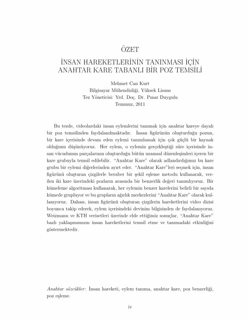
Figure 3.4: This figure shows a set of matched points between two frames be-longing to wave action when Left-To-Right matching is used. Matched points areconnected with green lines.
Once the points in frames f1 and f2 are matched by Left-to-Right matching
strategy, we employ Formula 3.3 to calculate an overall similarity value.
sim (f1, f2) =
∑|M |i=1 d(Mi)
|M |+ penalty × max (|P1| , |P2|)− |M |
max (|P1| , |P2|)(3.3)
Here, we denote the set of matching points as M . Each Mi, where i ranges
from 1 to |M |, represents a pair of matched points, one point belonging to P1 and
the other point belonging to P2. We denote the similarity distance between the
points in matched pair i as d (Mi). The first term and second term in the formula
measure two different aspects for expressing the overall similarity between frames
f1 and f2. The first term in the formula is the average of the similarity distances
between the matched points in M and it basically reflects how similar the shapes
of the human pose contained in frame f1 and f2 are. On the other hand, the second
term introduces an additional factor to the overall similarity by multiplying the
percentage of the number of unmatched points with a predefined constant referred
as penalty. We believe that representing similarity and dissimilarity of the shapes
in f1 and f2 in such a combined fashion gives us a more accurate comparison.

CHAPTER 3. OUR APPROACH 17
Figure 3.5: This figure illustrates another set of matched points between thesame frames in Figure 3.4 when Hungarian Method is used. Matched points areconnected with green lines.
3.2.1.2 Hungarian Method
An alternative matching method is the algorithm used in [1]. The Hungarian
Method is a combinatorial optimization algorithm and it gives the matching
between the elements of two sets that has the minimum total cost. Hungarian
Method is different from Left-To-Right Matching in the sense that it may not
match a point to its counterpart right away. Instead, it produces a matching in
which the global similarity distance summation is minimized. The details of this
matching scheme can be found in [14]. Figure 3.5 illustrates an example matching
between two frames by using the Hungarian Method.
sim (f1, f2) =
∑|M |i=1 d(Mi)
|M |(3.4)
Hungarian Method provides a one-to-one and onto matching, in which each
and every element in P1 is associated with exactly one element in P2. Since each
point in set P1 has a corresponding point in set P2, the second term in Formula
3.3 becomes inapplicable when Hungarian Method is in use. Therefore, in this
case, we employ Formula 3.4.

CHAPTER 3. OUR APPROACH 18
3.2.2 Utilizing Other Visual Clues
As indicated previously, similarity matrix SMsc holds the shape context similar-
ity between each pair of points in given frames f1 and f2. Both Left-To-Right
matching and Hungarian Method operate on SMsc and generate a set of matched
points. In order to calculate the similarity between points, one can utilize other
visual clues along with the shape context descriptor. It is observed that combin-
ing these clues together with the shape context usually results in more accurate
matches and consequently higher recognition rates.
In our work, we know the orientation θ of each line which originates our
sample points. We define the orientation distance between any two points pi and
pj by using Formula 3.5. Here, θi and θj denote the orientation values of the lines
where the points i and point j originate from.
dθ(i, j) =|θi − θj|π/2
(3.5)
By finding the orientation similarity between each pair of points, we generate
a similarity matrix SMθ. We can make use of the orientation similarity in the
point matching process by adding SMθ to SMsc and letting the matching strategy
operate on the resulting matrix. In fact, this approach can be generalized by
introducing other visual clues and taking a weighted combination of them as
depicted in Formula 3.6. In the experiments section, we show how using different
weights affect the overall recognition performance.
SM = αsc × SMsc + αθ × SMθ + αx × SMx + . . . (3.6)
3.2.3 Spatial Binning
An important constraint that can be exploited during the matching process is
the locations of the generated points in the image. For example, matching a

CHAPTER 3. OUR APPROACH 19
Figure 3.6: This figure illustrates the spatial binning applied to a human pose.Spatial binning approach can be generalized to any N X N binning. In this work,we use N as 2, which results in 2 X 2 spatial binning as shown in (a) and (b). (c)illustrates the tolerance value we define on spatial binning. Points in red shadedtransparent rectangles are the ones which are affected by the tolerance value. Forexample, the point shown in small yellow circle is considered as belonging to bothRegion 1 and Region 2.
point lying on an upper body contour to a point lying on a lower body contour
is not meaningful even if they have similar shape context descriptors. In order to
guarantee that no two points located on different parts of the human contour can
be matched, we first divide the human figure represented in a given frame into
4 bins such as upper body left, upper body right, lower body left and lower body
right. During the matching process, allowing the points to be matched only if
they come from the same bin region ensures this constraint. Figure 3.6 illustrates
dividing the human figure in an image into four bins. Clearly, this constraint can
be generalized into any N ×N binning.
When dividing a given frame into any N × N bin regions, we first calculate
the range of x and y coordinates of the points forming the human figure. Then,
we divide both ranges into N equal pieces. Drawing horizontal and vertical lines
which intersect the division points seperating these pieces gives us a N ×N grid
on the human figure. During the calculation of the boundaries that define a bin
region, it is likely to have some offsets in the x and y coordinates because of the

CHAPTER 3. OUR APPROACH 20
unsymmetrical shape of the human pose and/or imperfect edge detection results.
Such shifts may lead to some points to be contained in bin regions where they do
not belong.
In order to deal with this problem, we define a tolerance value on the spatial
binning. According to that, if a sample point is within a certain pixel distance to
the boundary that divides two bin regions, we consider that point to be contained
in both of them. Again, Figure 3.6 illustrates the tolerance value and its effect
on a point in the given example frame.
3.3 Finding Key Frames
Our approach presented in this thesis depends on the key frames we extract
from the available video sequences of each action. We define key frames as a
set of frames that uniquely distinguishes an action from others. Intuitively, to
find key frames, it is reasonable to group the frames which show common pose
appearances. Thus, we base our key frame extraction process on the k-medoids
clustering algorithm.
For each action ai consisting of n frames such as {f1, f2, . . . , fn}, a set of key
framesKFi with sizeK can be found as follows; first, a similarity matrix SMfrm is
created by means of Formula 3.3 or Formula 3.4, depending on the choice of point
matching strategy. Every element SMfrm (j, k) corresponds to the similarity be-
tween frame fj and fk. Then, similarity matrix SMfrm is given as the input to
k-medoids clustering algorithm. k-medoids partitions the frames {f1, f2, . . . , fn}into K clusters, where cluster medoids are {KFi1, KFi2, . . . , KFiK}. Since the
cluster medoids tend to represent common poses in each action, we define the
cluster medoids as the key frame set KFi for action ai. As the work in [24] in-
dicates, simple human actions can be classified almost instantaneously. In most
cases, using a very short sequence (1-10 frames) of key frames for each action is
enough to classify actions successfully. In our experiments, we keep the number
of representatives for each action as small as possible. On the other hand, we

CHAPTER 3. OUR APPROACH 21
Figure 3.7: This figure shows two extracted key frames for actions bend, jack,walk and wave presented in Columns 1 to 4, respectively.
observe that there are some factors which may result in a certain increase in the
number of required representatives for accurate classification. One example of
such factors is the actors performing a particular action in different ways. More-
over, the viewpoint and zoom factor of the camera can be listed as other factors
that have an affect on the number of key frames. We believe that increasing the
number of representatives to a certain point resolve such issues in most cases. In
the experiments section, we show the effects of K on the recognition performance.
Figure 3.7 illustrates the key frames that are extracted by our approach for two
different actions.
3.4 Utilizing Motion Information
Pose information itself is powerful enough to recognize most of the actions. How-
ever, ignoring the motion information encoded in an action sequence might be
intolerable when distinguishing actions such as walking and running which con-
tain similar pose appearances. Unfortunately, it is hard to involve a global motion
information in key frame based approaches, since the classification is performed
generally on a frame-by-frame basis. In order to deal with this shortcoming, we
associate two displacement vectors with each frame and introduce a level of mo-
tion information in the key frame selection process. These vectors, which we name
as fw (“from where”) and tw (“to where”), reflect the general displacement of

CHAPTER 3. OUR APPROACH 22
the points in a frame with respect to their positions in previous and next frame.
For a frame fi, we extract ~fwi vector in the following steps; first, we
initialize ~fwi with all zeros. ~fwi consists of 4 nonnegative components{fw+x
i , fw−xi , fw+yi , fw−yi
}which represent magnitude of the total displacement
of the points in +x,−x,+y and −y directions, respectively. Then, we gener-
ate points on the human contour of frames fi−1 and fi as described in Section
3.1.3. Next, by using the same point matching techniques explained in Section
3.2, we find corresponding matches between points of fi−1 and fi. Let (pj, pk) be
a matched pair of points, where pj lies on fi−1 and pk lies on fi. We calculate the
displacement in x and y coordinates of these points with Formula 3.7.
xdiff = xi−1,j − xi,kydiff = yi−1,j − yi,k
(3.7)
After calculating the displacement in x and y coordinates, we accumulate the
computed difference to the corresponding cell of ~fwi vector. For instance, if xdiff
is a positive value, we add |xdiff | to fw+xi . Otherwise, we add |xdiff | to fw−xi .
We update fw+yi or fw−yi in the same fashion depending on the sign of ydiff .
Repeating the same procedure for each matched pair of points results in ~fwi
which provides a level of motion information with respect to the previous frame.
We extract ~twi vector in a similar fashion. This time, instead of matching the
points with fi−1, we match the points of fi with next frame fi+1. As described
previously, we calculate the displacement magnitudes for each matched pair of
points and accumulate those values in ~twi vector. Figure 3.8 gives a feel of this
process by illustrating the counterpart of a point in the previous and next frames
and shows the displacement vectors for a single point.
There are multiple ways to integrate the extracted motion information into the
key frame selection process. In section 3.2.2, we emphasized that combining other
visual clues together with the shape context descriptors results in more accurate
measurements in defining the similarity between points. Moreover, in Formula
3.6, we showed how we can obtain a weighted combination of the similarity values

CHAPTER 3. OUR APPROACH 23
Figure 3.8: This figure shows the displacement vectors (drawn in red in middleframe) for the yellow point pk in the middle frame i. The point pj is the counter-part of pk in previous frame i - 1 whereas the point pm is its counterpart in nextframe i + 1. The red line going from yellow point to blue point shows where theyellow point is previously whereas the red line going from yellow point to greenpoint shows where it goes next. fw and tw vectors described below are composedby accumulating the individual displacement vectors for each matched point.
coming from different clues and produce an overall similarity matrix. We can
extend formula 3.6 in order to introduce motion information which are represented
by fw and tw vectors. We calculate the similarity between any two fw and tw
vectors by employing chi-square distance X2. Thus, the new formula becomes
the following;
SM = αsc×SMsc +αθ×SMθ +αfw×X2(fwi, fwj) +αtw×X2(twi, twj) (3.8)
As an alternative to incorporate motion information right into similarity ma-
trix, we can integrate the constants coming from X2(fwi, fwj) and X2(twi, twj)
in Formula 3.3 and 3.4. If this alternative approach is to be adopted, these
formulas take the following forms, respectively;
sim (f1, f2) =
∑|M |i=1 d(Mi)
|M |+penalty×max (|P1| , |P2|)− |M |
max (|P1| , |P2|)+X2(fwi, fwj)+X
2(twi, twj)
(3.9)

CHAPTER 3. OUR APPROACH 24
Figure 3.9: This figure demonstrates action recognition using Majority Votingclassification scheme. The given sequence is classified as “run” with 8 votes.
sim (f1, f2) =
∑|M |i=1 d(Mi)
|M |+X2(fwi, fwj) +X2(twi, twj) (3.10)
3.5 Recognizing Actions
In order to classify a given action sequence, we use three different classification
techniques; Majority Voting, Sum of Minimum Distances and Dynamic Time
Warping.
3.5.1 Majority Voting
Majority Voting can be described as a frame-by-frame basis comparison approach.
Given an action sequence consisting of frames {f1, f2, f3, . . . , fn}, for each frame
fi, we first compute the similarity values dj(i, k) between fi and all of the frames

CHAPTER 3. OUR APPROACH 25
KFjk in key frame set KFj = {KFj1, KFj2, KFj3, ..., KFjK} where j represents
an action in the available action set {a1, a2, a3, . . . , am} and K is the number of
key frames for each action.
Next, we find the minimum of dj (i, k) for all j and k and assign fi the action
label j which contains the minimum similarity value dj (i, k). In other words, we
apply a 1-NN classifier to fi and assign the action label of the nearest key frame
of all actions. Equation 3.11 describes this step in formal notation.
arg minj dj (i, k) ∀j 1 ≤ j ≤ m and ∀k 1 ≤ k ≤ K (3.11)
While labeling each frame in the same way, we keep a vector V =
{V1, V2, V3, . . . , Vm} which holds the number of frames assigned to each action.
Once all the labeling is done, we compare the values in V and classify the se-
quence {f1, f2, f3, . . . , fn} as the action that has the maximum number of votes.
This step is formulated in Equation 3.12. Moreover, Figure 3.9 illustrates classi-
fication of a sequence with Majority Voting.
arg maxc Vc ∀c 1 ≤ c ≤ m (3.12)
As an alternative to 1-NN classifier used for assigning an action label to a
frame, we can employ 3-NN classifier which we believe provides more accurate
results. While using 3-NN, we find the nearest three neighbours of each frame
fi. If any two of the three neighbours (key frames) belong to the same action j,
we assign fi action label j. However, if all of the three neighbours are contained
in key frame sets of different actions, we exclude frame fi from the classification
process. In the experiments section, we compare 1-NN and 3-NN and show which
one is superior over the other.

CHAPTER 3. OUR APPROACH 26
3.5.2 Sum of Minimum Distances
During our analysis, we observe that the poses in some key frames of different
actions may be very similar. For example, walking and running actions in Weiz-
mann dataset [9] share instances where it is very difficult to differentiate the two
actions from each other just by looking at the pose information in the figures.
Similarly, handclapping and handwaving actions in KTH dataset [25] contain
some frames where the human figure is facing the camera with arms sticking
to the body. Majority Voting labels such frames with the action which has the
most similar key frame. Therefore, when classifying a handwaving sequence, a
large number of frames can be labeled as handclapping. This clearly results in a
decrease in the recognition performance.
In order to minimize the effects of such common poses, we make use of the Sum
of Minimum Distances classification scheme. Given an action sequence consisting
of frames {f1, f2, f3, . . . , fn}, for each frame fi, we again compute the similarity
values dj (i, k) between fi and all of the frames KFjk in key frame set KFj =
{KFj1, KFj2, KFj3, ..., KFjK}. (We use the same notation in Section 3.5.1)
Instead of using a k-NN classifier for labeling fi right away, we find the mini-
mum dj(i, k) for each action j and accumulate those distances within a seperate
vector MD = {MD1,MD2,MD3, . . . ,MDm}. Equation 3.13 describes the up-
date of each element MDj (1 ≤ j ≤ m) of vector MD more formally. After
processing each frame of sequence {f1, f2, f3, . . . , fn} and updating the elements
of MD vector accordingly, we classify the sequence as action c which has the
smallest value MDc in MD vector. Equation 3.14 depicts how the final decision
is taken in mathematical notation.
MDj = MDj + min dj (i, k) ∀k 1 ≤ k ≤ K (3.13)
arg minc MDc ∀c 1 ≤ c ≤ m (3.14)

CHAPTER 3. OUR APPROACH 27
3.5.3 Dynamic Time Warping
Both of the previous classification schemes are based on the individual compar-
ison of each frame to key frames extracted for each action. Although they are
simple and straightforward to implement, Majority Voting and Sum of Minimum
Distances fail to catch the relative ordering of the poses occurred in an action
sequence. This drawback may manifest itself in deterioration of the recognition
rate when there exists some actions which consist of a set of poses encountered
in reverse order in time. As an example we can give sitting down and standing
up as a representative pair for these kind of actions.
Dynamic Time Warping (DTW) [23] is a technique that is being extensively
used in speech recognition. Taking its power from dynamic programming, DTW
compares two series with different sizes by finding an optimal alignment between
them. We employ DTW in order to align the poses of two action sequences and
find a correspondence between their pose order.
We classify a given action sequence as follows. By means of DTW, we
first compare the test sequence {f1, f2, f3, . . . , fn} with each training sequence
t = {t1, t2, t3, . . . , tl} where l is the length of the training sequence. An im-
portant point to emphasize here is that we do not use the training sequence
t = {t1, t2, t3, . . . , tl} as is. Instead, we represent it with a set of key frames of
action j which the training sequence belongs to. For example, instead of using
t1 during the comparison, we use key frame KFjc for a particular c (1 ≤ c ≤ K)
which is the most similar key frame to t1 among all of the key frames in KFj.
After comparing it with the training sequences of all actions, we classify the test
sequence as the action which has the training sequence that is most similar to
test sequence in DTW distance.

Chapter 4
Experiments
This chapter consists of the experiments that we have conducted to evaluate
our action recognition scheme. First, we describe the state of the art action
recognition datasets (Section 4.1). Then, we present the results we obtain on
these datasets (Section 4.2). Finally, we compare our results with the existing
works in the literature (Section 4.3).
4.1 Datasets
4.1.1 Weizmann
Weizmann dataset was introduced by Blank et al. in [9]. It consists of 9 actions
such as walk, run, jump, side, bend, wave1 (one-hand wave), wave2 (two-hands
wave), pjump (jump in place) and jack. The actions are performed by 9 different
actors. There are total of 81 videos in the entire dataset. When testing our
approach on Weizmann, we used the silhouette images, which are provided as part
of the dataset, for point generation step. We apply leave-one-out classification for
all of the experiments performed on this dataset. Figure 4.1 shows the example
poses taken from Weizmann dataset.
28

CHAPTER 4. EXPERIMENTS 29
Figure 4.1: This figure shows samples taken from 9 actions in Weizmann dataset.Top Row: bend, jack, jump Middle Row: pjump, run, side Bottom Row:walk, wave1,wave2
4.1.2 KTH
KTH dataset contains 6 actions (boxing, hand-clapping, hand-waving, jogging,
running, walking) performed by 25 different actors in 4 scenarios; outdoors (s1),
outdoors with changing scale and viewpoints (s2), outdoors with different clothes
(s3) and indoors with changing illumination (s4). There are total of 600 videos
in the entire dataset. Because of the large number of available frames for each
action, the key frame extraction step requires a significant amount of time. For
this reason, we split the dataset into two as training and test samples. Moreover,
instead of extracting K number of key frames for each action, we extract K
number of key frames for each scenario of each action. This leads having a total
of 4 × K number of key frames for each action. In KTH dataset, actions are
performed with varying periodicity. For consistency, we trim action sequences
to 20-50 frames so that the action is performed only once. Figure 4.2 shows the
sample frames taken from KTH dataset.

CHAPTER 4. EXPERIMENTS 30
Figure 4.2: This figure shows samples taken from 4 different shooting conditions(s1, s2, s3 and s4) of KTH dataset. Boxing, hand-clapping, hand-waving, jogging,running and walking actions are shown in Column 1 to 6 in the respective order.
4.2 Experimental Results
This section presents the experimental results we obtained by testing our ap-
proach on the Weizmann and KTH datasets.
4.2.1 Evaluation of Number of Key Frames
As our first experiment, we show how the number of key frames (K) affects recog-
nition performance. In Section 3.3, we indicated that human brain can recognize
an action instantenously just by looking at a single frame. This observation en-
courages us in using a small number for K in our experiments. Figure 4.3 shows
the recognition rate when the number of key frames extracted for each action is
2, 5, 10, 15, 20 and 50. The same figure also demonstrates the effect of spatial
binning discussed in Section 3.2.3. Previously, we noted that the spatial binning
approach can be generalized into any N × N binning. For our experiments, we
CHAPTER 4. EXPERIMENTS 31
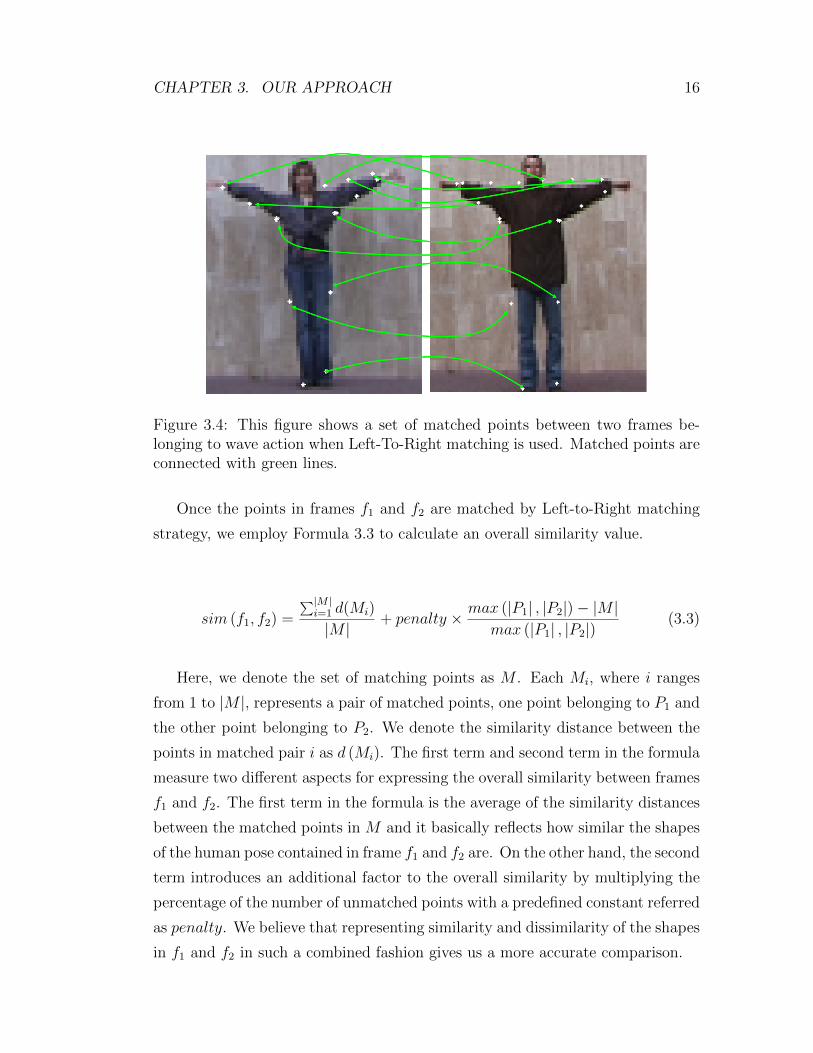
Figure 4.3: This figure illustrates the effect of the number of key frames andspatial binning option on recognition performance. grid off and grid on labelson x-axis represent the results when the spatial binning option is off and on,respectively.
use N = 2 to show the effectiveness of spatial binning.
As shown in the figure, the highest recognition rates are %93 and %94 and
they are obtained when the number of key frames employed to represent each
action is 20 and 50, respectively. The most noticeable trend in the results is the
large improvement of recognition rate when we increase the number of used key
frames from 2 to 5 and from 5 to 10. Once a saturation point is reached in terms
of K, increasing it (from 20 to 50) further results in a small step up of the overall
performance (from %93 to %94).
Figure 4.4 presents the confusion matrices of the best results in Figure 4.3.
Most of the confusion occur among jump-pjump and run-side-walk actions. Since
for this experiment we only utilize shape of human pose, it is quite reasonable
to have such misclassifications. Jump and pjump are basically variations of the
same action (jump is performed with motion towards a certain direction whereas
pjump is performed in place). Similarly, run, side and walk actions show quite
similar pose appearances and they mostly differ in speed the action is performed.

CHAPTER 4. EXPERIMENTS 32
Figure 4.4: This figure shows the confusion matrices of the best results in Figure4.3. We achieve %93 and %94 accuracy values when K = 20 (given in (a)) andK = 50 (given in (b)). Most of the confusions occur among jump - pjump andrun - side - walk actions.
Introducing a certain level of motion information would resolve these issues.
4.2.2 Evaluation of Spatial Binning and Tolerance
An important observation about the results in Figure 4.3 is the positive effect of
spatial binning option upto a certain point. Placing a 2×2 imaginary grid over the
human figure and allowing the points to be matched only if they come from the
same grid region leads to reasonable jumps in the accuracy (from %50.6 to %59.3
when K = 10 and from %74.1 to %76.1 when K = 15). However, the results when
K = 15, 20, 50 and spatial binning turned off overperform the results with the
same number of key frames when spatial binning is turned on. As emphasized in
Section 3.2.3, we believe that this expected decrease is caused by the imperfections
in the boundary coordinates of spatial bin regions for some test sequences. To
reduce negative effect of the miscalculations, we introduce a tolerance value which
enables the points that fall in two neighbor bin regions to be matched if they

CHAPTER 4. EXPERIMENTS 33
Figure 4.5: This figure illustrates the effect of tolerance on results when spatialbinning is turned on. Tolerance value is defined in pixel units. (3 pixels, 5 pixels,7 pixels and 9 pixels)
are located within a certain distance to the boundary between those regions.
Figure 4.5 shows the effect of tolerance value on recognition performance when
repeating the experiment in Figure 4.3 with tolerance = 3, 5, 7, 9 and K = 20.
Increasing tolerance value from 3 to 9 provides a considerable elevation (%7) and
provides the same recognition rate %93 as its counterpart when spatial binning
is disabled. Defining a tolerance value gives us a more flexible version of original
spatial binning constraint. Moreover, it clearly provides a better recognition
performance for all K when compared to the results where no spatial binning
constraint is enforced.
4.2.3 Adjusting Sampling Factor for Point Generation
In Section 3.1.3, we emphasized the importance of feeding the shape context al-
gorithm with a good set of points for the accurate representation of the pose in
a given frame. As the number of points sampled from human contour increases,

CHAPTER 4. EXPERIMENTS 34
Figure 4.6: This figure shows the effect of sampling factor s used in point gen-eration. As the sampling factor gets larger, the recognition rate improves to acertain point and then fluctuates slightly within a certain band of accuracy.
shape context gets better in fetching the shape formed by the human pose. Fig-
ure 4.6 illustrates the effect of sampling factor s we use for point generation on
recognition accuracy. When sampling factor s is 0, we only utilize the center
points of the extracted lines as sampled points. As the figure clearly shows, using
only center points is not enough for good classification. The big jump in recog-
nition rate (from %61.5 to %93.1) after setting sampling factor to 1 is a strong
indication of sampling factor being a crucial parameter.
4.2.4 Evaluation of Different Classification Techniques
For recognizing actions, we utilize four different classification schemes; Majority
Voting with 1-NN, Majority Voting with 3-NN, Sum of Minimum Distances and
Dynamic Time Warping. The first three schemes can be described as having
similar natures since all three of them are based on individual comparison of each
frame to key frames of all actions. On the other hand, aligning two pose sequences
and finding the best possible pose order between them, Dynamic Time Warping

CHAPTER 4. EXPERIMENTS 35
Figure 4.7: This figure illustrates the recognition accuracies provided by eachclassification method. In the figure, MV 1-NN, MV 3-NN, SD and DTW standfor Majority Voting with 1-NN, Majority Voting with 3-NN, Sum of MinimumDistances and Dynamic Time Warping, respectively.
provides a different recognition alternative. Figure 4.7 shows the performances
of each scheme in an experiment on Weizmann dataset, where the number of key
frames K for each action is 40 with spatial binning option turned off. As expected,
the first three methods (MV 1-NN, MV 3-NN and SD) are able to recognize
almost the same amount of samples and present recognition rates between %91
and %93. Surprisingly, DTW appears as the worst classifier and remains at
merely %50 accuracy. From these observations, we can conclude that Dynamic
Time Warping is not suitable to be used along with a key frame based action
recognition approach. For the rest of the experiments, we drop DTW and utilize
MV 1-NN, MV 3-NN and SD as our classifiers.
4.2.5 Evaluation of Matching Methods
In Section 3.2.1, we present two point matching techniques Left-To-Right Match-
ing (LRM) and Hungarian Method which are used to find a matching between
the point sets of a given pair of frames. Looking at different perspectives, these
two matching methods provide different strategies. LRM tries to match each

CHAPTER 4. EXPERIMENTS 36
Figure 4.8: This figure demonstrates how using Left-To-Right Matching (LRM)or Hungarian Method affects the recognition performance. LRM provides a %93recognition rate whereas Hungarian Method remains at %86
.
point in first frame to the most similar point in second frame, but it does not
necessarily provide a match for each and every point. On the other hand, provid-
ing a match for each point, Hungarian Method seeks to minimize summation of
individual similarities by avoiding to match the closest points right away. Figure
4.8 shows that using Left-To-Right Matching (LRM) overperforms Hungarian
Method. This observation is important since it is an indication of Hungarian
Method not being applicable to human action recognition as a point matching
technique to define the similarity between two human poses. Although Belongie
et al. in [1] suggest Hungarian Method when using Shape Context Descriptor,
LRM is more successful in analysing similarities and dissimilarities of a given pair
of human pose. Moreover, Hungarian Method, which is essentially a combina-
torial optimization algorithm, takes a considerable time when looking for global
optimum. For the rest of the experiments, we do not test Hungarian Method and
utilize Left-To-Right Matching as our point matching scheme.
CHAPTER 4. EXPERIMENTS 37
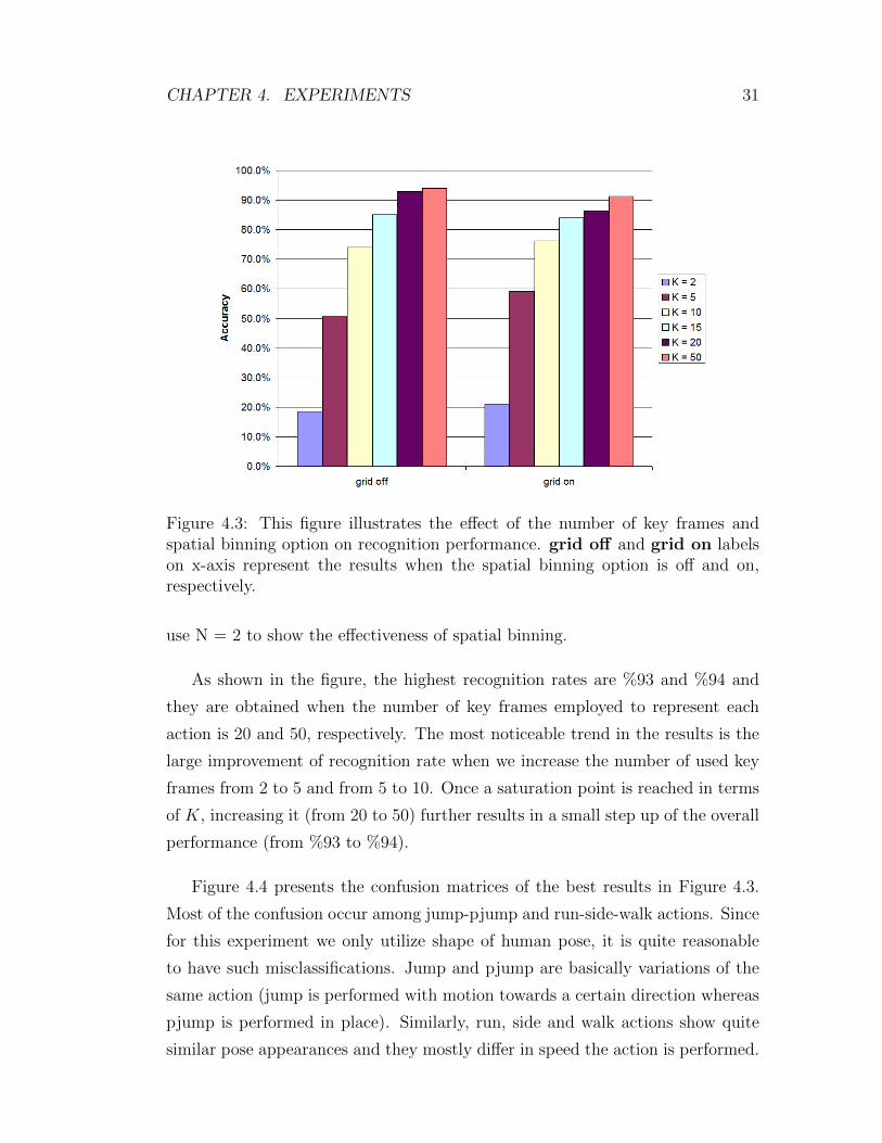
4.2.6 Utilizing Other Visual Clues
It is desirable to use other visual clues such as image appearance in combination
with Shape Context Descriptor when defining a similarity value between two
points. As we emphasized in Section 3.2.2, these individual distances can be
summed up by a weigted manner and similarity matrix between points can be
generated accordingly. With Formula 3.5, we defined a distance which measures
the similarity of two points in terms of orientation of the lines that the points are
originated from. Our results show that none of different weight sets (αsc, αθ) that
we give to each similarity value (shape context distance and orientation distance)
improves our previous results. In fact, increasing the effect of orientation distance
may sometimes result in the deterioration of recognition performance. We believe
that involving the other line characteristics such as line length in Formula 3.5
may give us the improvement we seek for. We leave the exploration of such
supplemental line features as a future work.
4.2.7 Involving Motion Information
In Section 3.4, we explained how we can introduce a level of motion information to
the key frame selection process. We described how we compute two displacement
vectors referred as “from where” and “to where” for each frame in a sequence.
As mentioned previously, there are two ways to integrate the motion information.
One way is to calculate the distance between displacement vectors of two frames
and to add the resulting value as a constant to shape context similarity values of
points at the beginning of point matching. This method is desribed by Formula
3.9. Alternatively, after point matching is done, we can add the same values to the
distance between two frames as depicted in Formula 3.10. In our experiments, we
observed that the first alternative does not give us the performance improvement
we seek for. Thus, in this section, we only focus on the second alternative.
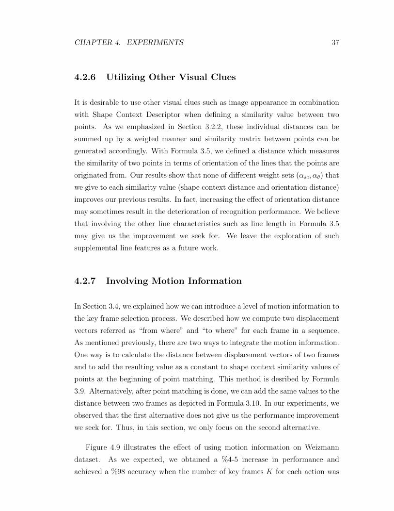
Figure 4.9 illustrates the effect of using motion information on Weizmann
dataset. As we expected, we obtained a %4-5 increase in performance and
achieved a %98 accuracy when the number of key frames K for each action was

CHAPTER 4. EXPERIMENTS 38
Figure 4.9: This figure illustrates the effect of using Motion information alongwith Shape on Weizmann dataset. When the number of key frames K for eachaction is 80, we obtained a %98 accuracy.
80. Figure 4.10 presents the confusion matrix of the same result. As it can be
seen, the only confusions occur between pjump-wave1 and run-walk. This result
seems quite reasonable since pjump and wave1 actions only differ by a single
hand in shape. Besides this confusion, the same up and down movement of the
points in their poses is another factor which makes them hard to be distinguished
by our displacement vectors. Moreover, the second confusion between run and
walk sequence might be a good indication of the need to use a global motion
information.
Figure 4.11 shows the performance of using only shape information and using
shape and motion information together on KTH dataset. Our approach without
using motion information achieves a %77 recognition rate when the number of key
frames we extracted for each action is 120 (30 key frames for each scenario for each
action). When involving motion information, we obtain %4 improvement and
achieve %81 accuracy. In this result, the individual performance values obtained
for each shooting scenario are %92 for SC1, %64 for SC2, %85 for SC3 and %79 for
SC4. SC2 videos are shot in presence of scale and viewpoint variations leading
to a considerably large number of possible pose appearances for each action.

CHAPTER 4. EXPERIMENTS 39
Figure 4.10: This figure shows the confusion matrix for the best result in Figure4.9
.
Therefore, SC2 appears as the shooting condition where our approach works the
worst. Here, increasing the number of poses should increase the performance
upto a certain point. However, increasing K further also increases the required
time for the classification step. Figure 4.12 presents the confusion matrix for the
best result in Figure 4.11. Generally, the confusions occur among two groups;
boxing-handclapping-handwaving and jogging-running-waving. Especially, the
failure in recognizing running action stands as a striking observation. Again, this
observation is another clear indication of the absolute need in utilizing a global
motion feature.
We believe that the results we obtained on this dataset are acceptable since
KTH is quite a challenging dataset with different shooting conditions. Moreover,
because of time concerns we split this dataset as testing and training, but it
is known that applying leave-one-out cross validation may provide performance
improvements upto %10.

CHAPTER 4. EXPERIMENTS 40
Figure 4.11: This figure illustrates the effect of using Motion information alongwith Shape on KTH dataset. When the number of key frames K for each actionis 120 (30× 4), we obtained a %81 accuracy.
.
Figure 4.12: This figure shows the confusion matrix for the best result in Figure4.11
.

CHAPTER 4. EXPERIMENTS 41
4.3 Comparison to Related Studies
In this thesis, our first goal was to present a new representation that combines
shape and motion information in an action sequence within a key frame based
approach. Most of the recent approaches have perfect recognition rates (%100)
on Weizmann dataset. Although we achieved %98 accuracy on this dataset, we
were unable to classify only 2 sequences out of 81 and we managed to get better
results compared to the studies in [20] (%73) and [27] (%87). In KTH dataset,
the performance values previous studies achieve range from %73 [25] to %95 [16].
Using a split-based testing method, our approach achieves a %81 accuracy and
performs better than the studies in [13] (%80), [18] (%73) and [25] (%72).

Chapter 5
Conclusion
5.1 Summary and Discussion
In this thesis, we present an action recognition approach that is based on a num-
ber of stored pose prototypes (“key frames”) for each action. To describe the
human pose represented in a frame, we use the well-known Shape Context De-
scriptor which is generally employed for object recognition purposes. We compare
the shapes of the poses in a given pair of frames by means of Shape Context De-
scriptor. During the shape comparison phase, we also utilize simple displacement
vectors (“from where” and “to where”) that we compute for each frame and in-
troduce a level of motion information to the key frame selection process. As a
final step, grouping the frames into a predefined number of clusters provides us a
set of key frames for each action which makes it easier to distinguish that specific
action from the rest of the action set.
For classifying a given sequence of poses, we utilize three schemes; Majority
Voting, Sum of Minimum Distance and Dynamic Time Warping. Majority Voting
and Sum of Minimum Distances can be categorized as frame-by-frame comparison
schemes and they are simple and powerful enough to find the most similar action
to a given pose sequence. On the other hand, Dynamic Time Warping, which
finds a correspondence between the pose order of two action sequences, can also
42
CHAPTER 5. CONCLUSION 43
be utilized as an alternative classification scheme.
The experiments we have conducted on Weizmann and KTH datasets show
that Shape Context is a powerful shape descriptor and it is efficient to grasp
the nature of the poses formed by the human figure during the time an action
is performed. Moreover, on top of describing the shapes by Shape Context,
employing a set of frames as “key frames” is indeed desirable compared to using
whole sequences in training samples. Moreover, our results indicate that even
simple displacement vectors for motion can eliminate shortcomings of merely
using the human pose and elevate recognition accuracy considerably.
5.2 Future Work
Classification performance of our approach presented in this thesis mostly de-
pends on the step in which we group the similar frames of an action into a
predefined number of clusters. Measuring how well the frames of an action are
grouped appears as the preferred work for future research. Evaluation of clusters
by existing Data Mining techniques and reassigning frames into clusters if neces-
sary may lead to significant increases in recognition accuracy. Our experimental
work shows that utilizing the local motion information present in a frame boosts
up performance to a certain point. Yet still, employing some features that reflects
the global motion information in the sequence is desirable. Therefore, inspecting
the motion in each frame and generating a general displacement vector for the
entire sequence stands as a second future work. When calculating similarity be-
tween two points, combining Shape Context distance with orientation distance in
weighted fashion does not elevate recognition performance. We will modify the
orientation distance in a way such that it reflects other line characteristics such
as length as well. As a last future work, we plan on letting each classification
technique take a role in the overall decision process. Although the individual
performance of Dynamic Time Warping is far from being acceptable, we believe
that combining Majority Voting or Sum of Minimum Distances with Dynamic
Time Warping would give us a more powerful classifier.

Bibliography
[1] S. Belongie, J. Malik, and J. Puzicha. Shape context: A new descriptor for
shape matching and object recognition. NIPS, pages 831–837, 2000.
[2] M. Blank, L. Gorelick, E. Shechtman, M. Irani, and R. Basri. Actions as
space-time shapes. ICCV, 2005.
[3] A. F. Bobick and J. W. Davis. The recognition of human motion using
temporal templates. Pattern Analysis and Machine Intelligence, 23:257–267,
2001.
[4] S. Carlsson and J. Sullivan. Action recognition by shape matching to key
frames. Workshop on Models versus Exemplars in Computer Vision, 2001.
[5] P. Dollar, V. Rabaud, G. Cottrell, and S. Belongie. Behavior recognition via
sparse spatio-temporal features. VS-PETS, 2005.
[6] A. A. Efros, A. C. Berg, G. Mori, and J. Malik. Recognizing action at a
distance. ICCV, 2003.
[7] A. Fathi and G. Mori. Action recognition by learning mid-level motion
features. CVPR, 2008.
[8] V. Ferrari, L. Fevrier, F. Jurie, and C. Schmid. Groups of adjacent contour
segments for object detection. IEEE Trans. Pattern Anal. Mach. Intel l.,
30:36–51, 2008.
[9] L. Gorelick, M. Blank, E. Shechtman, M. Irani, and R. Basri. Actions as
space-time shapes. ICCV, 2005.
44
BIBLIOGRAPHY 45
[10] K. Hatun and P. Duygulu. Pose sentences: a new representation for action
recognition using sequence of pose words. ICPR, 2008.
[11] N. Ikizler, R. G. Cinbis, and P. Duygulu. Human action recognition with
line and flow histograms. ICPR, 2008.
[12] N. Ikizler and P. Duygulu. Human action recognition using distribution of
oriented rectangular patches. Image and Vision Computing, 27, 2009.
[13] Y. Ke, R. Sukthankar, and M. Hebert. Spatio-temporal shape and flow
correlation for action recognition. Visual Surveillance Workshop, 2007.
[14] H. W. Kuhn. The hungarian method for the assignment problem. Naval
Research Logistics Quarterly, 2:83–97, 1955.
[15] I. Laptev, M. Marszalek, C. Schmid, and B. Rozenfeld. Learning realistic
human actions from movies. CVPR, 2008.
[16] Z. Lin, Z. Jiang, and L. S. Davis. Recognizing actions by shape-motion
prototype trees. ICCV, 2009.
[17] J. Liu and M. Shah. Learning human actions via information maximization.
CVPR, 2008.
[18] J. Liu, J. Yang, Y. Zhang, and X. He. Action recognition by multiple features
and hyper-sphere multi-class svm. ICPR, 2010.
[19] G. Loy, J. Sullivan, and S. Carlsson. Pose based clustering in action se-
quences. Workshop on Higher-Level Knowledge in 3D Modeling and Motion
Analysis, 2003.
[20] J. C. Niebles, H. Wang, and L. Fei-Fei. Unsupervised learning of human ac-
tion categories using spatial-temporal words. International Journal of Com-
puter Vision, 79(3):299-318, 2008.
[21] S. Nowozin, G. Bakir, and K. Tsuda. Discriminative subsequence mining for
action classication. ICCV, 2007.

BIBLIOGRAPHY 46
[22] H. Qu, L. Wang, and C. Leckie. Action recognition using space-time shape
difference images. ICPR, 2010.
[23] L. Rabiner and B. Juang. Fundamentals of speech recognition. 1993.
[24] K. Schindler and L. V. Gool. Action snippets: how many frames does human
action recognition require? CVPR, 2008.
[25] C. Schuldt, I. Laptev, and B. Caputo. Recognizing human actions: a local
svm approach. ICPR, 2004.
[26] C. Thurau and V. Hlavac. Pose primitive based human action recognition
in videos or still images. CVPR, 2008.
[27] C. Thurau and V. Hlavac. Pose primitive based human action recognition
in videos or still images. CVPR, 2008.
[28] Y. Wang, P. Sabzmeydani, and G. Mori. Semi-latent dirichlet allocation: a
hierarchical model for human action recognition. ICCV Workshop on Human
Motion, 2007.