A Journal of the Thermoforming Division of SPE Putting the PLA...
40
Fourth Quarter 2017 | Volume 36 | Number 4 A Journal of the Thermoforming Division of SPE IN THIS ISSUE: Reducing PLA Production Cost Process Optimization of Single Screw Systems for Polyolefins Volumetric Absorption Part 3: DMP Putting the PLA in Plastic
Transcript of A Journal of the Thermoforming Division of SPE Putting the PLA...
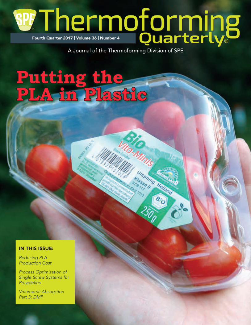
Fourth Quarter 2017 | Volume 36 | Number 4
A Journal of the Thermoforming Division of SPE
IN THIS ISSUE:
Reducing PLA Production Cost
Process Optimization of Single Screw Systems for Polyolefins
Volumetric Absorption Part 3: DMP
Putting thePLA in Plastic
2 SPE Thermoforming Quarterly
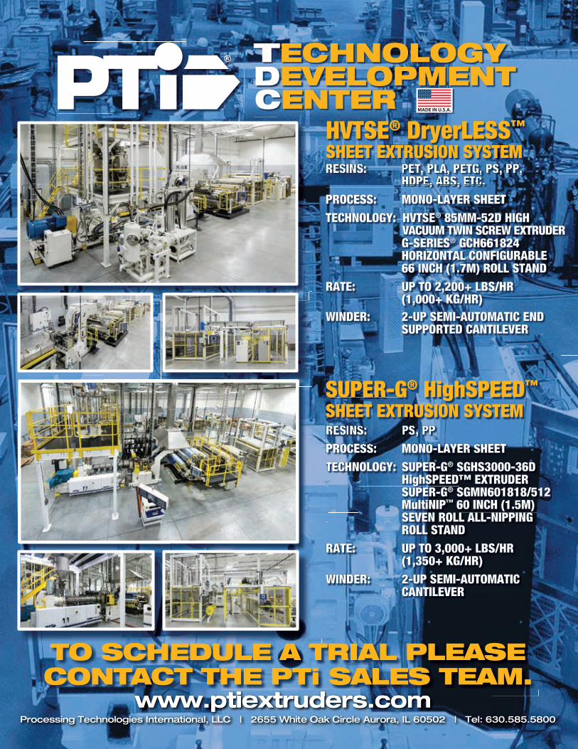
RESINS: PET, PLA, PETG, PS, PP, HDPE, ABS, ETC.PROCESS: MONO-LAYER SHEETTECHNOLOGY: HVTSE® 85MM-52D HIGH VACUUM TWIN SCREW EXTRUDER G-SERIES® GCH661824 HORIZONTAL CONFIGURABLE 66 INCH (1.7M) ROLL STANDRATE: UP TO 2,200+ LBS/HR (1,000+ KG/HR)WINDER: 2-UP SEMI-AUTOMATIC END SUPPORTED CANTILEVER
RESINS: PET, PLA, PETG, PS, PP,HDPE, ABS, ETC.
HVTSE® DryerLESS™
SHEET EXTRUSION SYSTEM
RESINS: PS, PPPROCESS: MONO-LAYER SHEETTECHNOLOGY: SUPER-G® SGHS3000-36D HighSPEED™ EXTRUDER SUPER-G® SGMN601818/512 MultiNIP™ 60 INCH (1.5M) SEVEN ROLL ALL-NIPPING ROLL STANDRATE: UP TO 3,000+ LBS/HR (1,350+ KG/HR)WINDER: 2-UP SEMI-AUTOMATIC CANTILEVER
RESINS: PS, PPPROCESS MONO LAYER SHEET
SUPER-G® HighSPEED™
SHEET EXTRUSION SYSTEM
TECHNOLOGYDEVELOPMENT CENTER MADE IN U.S.A.
TO SCHEDULE A TRIAL PLEASECONTACT THE PTi SALES TEAM.
PT R
RP
SS
TO SCHEEDULE A THE
SPE Thermoforming Quarterly 3
n DepartmentsChairman’s Corner | 4
New Members | 6-7
Thermoforming in the News | 8-12
The Business of Thermoforming: Global Trends 2017 | 14-16
Thermoforming & Sustainability: Reducing PLA Production Cost | 34-35
n FeaturesIndustry Practice: From the Archives | 18
How Important is the Volumetric Absorption Concept? Part 3: DMP | 20-24
Process Optimization of Single-Screw Systems for Polyolefin Resins | 26-33
n In This IssueSPE Council Summary | 36-37
A JOURNAL PUBLISHED EACH CALENDAR QUARTER BY THE THERMOFORMING DIVISION
OF THE SOCIETY OF PLASTICS ENGINEERS
www.thermoformingdivision.comEditor
Conor Carlin(617) 771-3321
SponsorshipsLesley Kyle
(914) [email protected]
Conference CoordinatorLesley Kyle
(914) [email protected]
SPE Thermoforming Quarterly® is published four times annually as an informational and educational bulletin to the members of the Society of Plastics Engineers, Thermoforming Division, and the thermoforming industry. The name, “SPE Thermoforming Quarterly®” and its logotype, are registered trademarks of the Thermoforming Division of the Society of Plastics Engineers, Inc. No part of this publication may be reproduced in any form or by any means without prior written permission of the publisher, copyright holder. Opinions of the authors are their own, and the publishers cannot be held responsible for opinions or representations of the authors. Printed in the U.S.A.
SPE Thermoforming Quarterly® is reg-istered in the U.S. Patent and Trademark Office (Registration no. 2,229,747). x
Fourth Quarter 2017 | Volume 36 | Number 4
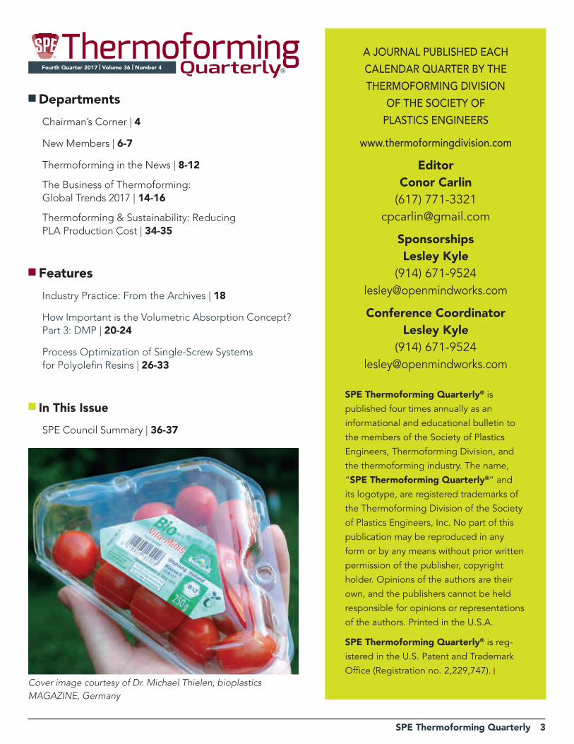
Cover image courtesy of Dr. Michael Thielen, bioplastics MAGAZINE, Germany
4 SPE Thermoforming Quarterly
Chairman’s Corner
Overcoming Adversity
Looking back at my last remarks in the Q3 issue, I was
pretty fired up about everything the Board of Directors
had planned for the Orlando conference. As we all know,
September was an incredible month, and not for the best
of reasons. We took the decision to cancel our flagship
event in light of the scope and scale of Hurricane Irma.
Though we were all disappointed, it was the right decision
and the board’s decision was unanimous. Much of what was
planned for this year will be transferred over to next year.
We are grateful to our exhibitors, sponsors and attendees
who have worked through the various logistical and
financial challenges to get ready for 2018 in Fort Worth.
Despite the adversity, our Division remains one of the
strongest groups within SPE. We continue to support
our educational programs though both scholarships
and matching grant funds. I encourage all companies to
consider opportunities to engage with the next generation
of plastics professionals, whether through direct hiring of
recent graduates and interns, through sponsorship of the
highly successful PlastiVan™ program, or through direct
outreach to your local schools. Planting the seeds today
will result in a strong and healthy employee harvest in the
future.
This edition of the magazine is lighter than what we would
usually see for the fourth quarter. Without any coverage
of the conference, including our multi-page spread for
the Parts Competition, we are missing a few notable
sections. Still, you will see some great content in the form
of Part 3 of Dr. Throne’s work on volumetric absorption
models (pp. 20-24) and a really inspiring news story from
Prent Corporation (pp. 9-10). Bioplastics continue to show
robust growth in all geographic markets and our story
from Europe illustrates new work being done to manage
production costs of PLA (pp. 34-35). In the business
section, we provide a summary of the annual PLASTICS
Global Trends report which takes the pulse of the entire
plastics value chain, from resin production to apparent
consumption of plastic products.
As we approach the holidays and the end of the year, we
start to reflect on 2017 and start to plan for 2018 (if we
haven’t already!) As a division, we are exploring new ways
to enhance member value and communication through
increased use of digital content. SPE continues to invest in
its IT infrastructure and new developments will be released
in Q1 2018. We encourage our members to get involved
in “The Chain” where many tough application questions
are being asked and innovative answers are provided by a
network of experts.
Speaking of questions, what else can we be doing for
you? Get in touch with your local board member or SPE
Councilor. For now, on behalf the entire Division board,
thank you for your continued support and enjoy the
holidays! |
Bret Joslyn
SPE Thermoforming Quarterly 5
6 SPE Thermoforming Quarterly
New Members
David AbolarinHematiteGuelph, ON Canada
Yordano AliceaProductive Plastics Mt. Laurel, NJ
Robert AnderlikSekisui Polymer Bloomsburg, PA
Marc-Wayne Anglin First QualityPackaging SolutionsRiviera Beach, FL Craig ArmstrongJetta Corp.Edmond, OK
Arnold BangelMeyer Plastics Indianapolis, IN
Corey BangsCW Thomas Philadelphia, PA
Matthew BellMilliken & Co. Spartanburg, SC Mark BergeronDolco Packaging Lawrenceville, GA Lars Bergheim Reifenhauser Cast Sheet CoatingTroisdorf, Germany
Lars BeringGibo PlastSkjern, Denmark
Kyle BrinkleyMcLean Packaging Corp. Nazareth, PA Reuben BurtonDisplay PackCedar Springs, MI Robert CardonaProductive Plastics Mt. Laurel, NJ
Alan CarterCarter AssociatesBurr Oak, MI
Alex CarterCarter AssociatesBurr Oak, MI
Donny CashoPeak Technology Ent.San Jose, CA Chad CecilMeyer Plastics Indianapolis, IN
Alain ChoquetReydel Automotive Harnes, France
Heath CloseBayerIndianola, PA Paul CoalsonPrimex PlasticsOakwood, GA Rebecca Cramer Asahi Kasei Plastics Fowlerville, MI
Nicholas DavidNestleFremont, MI Stephen DavisVeluxGreenwood, SC
Carlos De La Pena Triumph PrecisionCalexico, Baja Mexico
William Dillen Brentwood Industries Reading, PA
Bradley ElledgePrecision Formed PlasticsIrving, TX Mike EllermanCK Technologies Montpelier, OH
Andrew FitzGeraldFlight Extruded Plastics Melbourne, Victoria Aus.
Andrew Fitzsimmons FitzpakMarlboro, NJ
William Foran HEITRONICS Infrared Ewing, NJ Nicholas Frederick ThermoFlexMorrison, TN
Megan FreemanFreetech PlasticsFremont, CA
Chris Gallagher Brentwood Industries Reading, PA
Satya GargAnchor Packaging Ballwin, MO
Mark Gonyar Klockner-Pentaplast Charlottesville, VA Tra GossAsahi Kasei Plastics Waterford, MI
Brad GrimmGrimm Brothers Plastics Wapello, IA
Simon HamelDX PLASTIQUESLevis, QC Canada
Victor HansenDisplay PackCedar Springs, MI Sharon Haverlak Sekisui Polymer Bloomsburg, PA
Bill Hiltz Best Cutting DieSkokie, IL
Kenneth Hitchcock MMCCCorunna, MI Stewart HoyHematiteGuelph, ON Canada
Darrell JacksonAsahi Kasei PlasticsCamden, SC
Martin JohnsonJabilKittery, ME Milos Jokic ODC Tooling & Molds Waterloo, Canada
Josh KasinskasGSCGermantown, WI James Keith K&K Thermoforming Southbridge, MA Daesung KimPlastech co ltdKimhae, Kyung-Nam S.K.
Randy KressWilbert Plastic Services Belmont, NC Matt KuhnsLIXIL Water Technology Salem, OH John LahlouhBay Materials LLCFremont, CA
Martin LarsenMinimizerBlooming Prairie, MN Mark LewisLH GroupDoral, FL Rudy MacdonelFresh Pak CorpHouston, TX
SPE Thermoforming Quarterly 7
Bryan MargariaJohn DeereApex, NC
Jon Markwood ThermoFlexMorrison. TN
Marilyn MaticeDart ContainersMason, MI Wayne McElreathTriumph PrecisionCalexico, Baja Mexico
Todd McKechnieSekisui PolymerEast Hampstead, NH Arpad MihalyfiPro-Form KftBudapest, Hungary
Al MillerMcLean Packaging Corp. Nazareth, PA Virgil MinorSekisui Polymer Bloomsburg, PA Clóvis MiyoshiPLM Plásticos SAParana, Brazil
Colleen Moore Brentwood Industries Reading, PA Nate MortonADO ProductsPlymouth, MN Trevor Nickerson Jamestown Plastics Brocton, NY Stephen OrrothUniversity Mass. - Lowell Lowell, MA Allison Osmanson University of North Texas Denton, TX
Steven PetinakisPACT GroupRichmond, Vict. Aus.
Ryan PilgerKaddas Enterprises Salt Lake City, UT Richard Pomfret C. W. Thomas LLC Philadelphia, PA Michael PregontGOEX Corp.Janesville, WI Chris PreuschoffODC Tooling & Molds Waterloo, ON Canada
Robert QuinlanHC CompaniesTwinsburg, OH
Francois RabyPlastique ArtSainte Claire, QC Canada
Tanner Rahauser Brentwood Industries Reading, PA Rex ReeceVeluxGreenwood, SC Mark RepkoSonocoHartsville, SC John RhoadesPlacon Corp.Fitchburg, WI Chance RoseAmerican Tool And EngineeringGreene, IA Tom SadwadskiMarbachQuakertown, PA Jason ScruggsDowcoManitowoc, WI
Garrett SmithProfile PlasticsLake Bluff, IL Richard SnideApproved Aeronautics Corona, CA
Jea So100BIOEl Segundo, CA
Antonio StaffoniPolytype/OMVVerona, Italy
Jerome Stegall Anchor Packaging Jonesboro, AR
Riley StevensBraskem Philadelphia, PA
Myles StriebichBayerIndianola, PA
Jack StritchHampel Corp. Germantown, WI Tony SwihartPatrick Industries Bremen, IN Martin TroudtD6 Inc.Portland, OR
Jose UrzuaTriumph Precision Calexico, Baja Mexico
Valentino Verdiny Peak Technology Ent. San Jose, CA
Gil VieiraPLM Plásticos SA Parana, Brazil
Zeneida Vogt ExxonMobil Chemical Spring, TX
Joshua WagnerPenn State Erie,The Behrend College South Park, PA
Anthony Wangelin Placon Corporation DeForest, WI
Stacy WareSilgan PFCUnion, MO
Chad Weitzenkamp American Tool & EngineeringGreene, IA James Wickham CovestroSheffield, MA
Simon Wiedman Donarra Extrusions LLC Ocala, FL Richard Zimmerman Kaddas Enterprises Salt Lake City, UT
Why Join?
Why Not?
It has never been more important to be a member of your professional society than now, in the current climate of change and global growth in the plastics industry. Now, more than ever, the information you access and the personal networks you create can and will directly impact your future and your career. Active membership in SPE – keeps you current, keeps you informed, and keeps you connected. Visit www.4spe.org for details.
The question really isn’t “why join?” but …
8 SPE Thermoforming Quarterly
Thermoforming In The News
Coveris Develops In-Mold Calibration System for PP Coffee Capsulesby PackagingEurope.comAugust 23, 2017 – Coveris Rigid´s Center of Development & Innovation together with its partners Kiefel and Bosch-Sprang have recently developed a new and unique manufacturing technology for thin wall thermoformed containers.
This presents the opportunity to calibrate thermoformed products such as single serve Barrier PP-Cups during the thermoforming process and achieves beneficial material distribution resulting in product performance comparable to existing PS solutions.
During the industry fair K 2016, Coveris Rigid, Kiefel and Bosch-Sprang agreed to a common development project focusing on an alternative to the single serve Barrier PS-Cups with a sustainable PP solution for the Northern American market. The partnership has resulted in a new technology and has been ramped-up on 91-cavity thermoforming system with in-mold calibration with an annual capacity of 750 million single serve Barrier PP-Cups. The system has been developed to produce standard single serve coffee cups for use in North America. These products can be easily customized to different decoration requirements like coloring, embossing, etc.
The collaboration with the technology leaders, Kiefel and Bosch-Sprang, was focused on an alternative to polystyrene used for most of the existing cups. To simulate the performance of existing PS-cups and to ensure the puncture during the brewing process, material distribution of the Multi-Layer Barrier PP-Cup became the major challenge of the development. Together with the experience of the tool manufacturer Bosch-Sprang and based on existing patents, a calibration technology has been developed and installed in the 91-cavity system. The calibration technology allows for control of the material distribution in the most critical areas of the cups and achieve excellent side wall stability and uniform bottom thickness. The 3 partners Kiefel, Bosch-Sprang and Coveris Rigid, have aligned on an exclusivity agreement for the use of the In-mold Calibration Technology.
The development is a 100% sustainable/recyclable solution with all in-line process waste reverting back to the multi-layer structure. The chosen overall composition allows for
the cup to be recovered in the post-consumer recycling process. Coveris is also capable of offering a barrier PP-lid replacement for the Aluminum lids and in turn present a single material solution to the market.
Coveris has seen increased requests to develop sustainable thermoforming solutions in Polypropylene. This recent project is just one in a series of technology projects where Coveris has proven its expertise for complex PP thermoforming solutions in food and non-food product applications. The reduction of in-process waste and the use of post-consumer material is a major focus of Coveris’ environmental strategy: lowering the need for virgin material, and reducing our carbon footprint.
Spartech Closing Factory, Cutting Jobsby Michael Lauzon, Plastics News
October 11, 2017 – Spartech LLC Spartech, formerly PolyOne’s Designer Structures & Solutions unit, was acquired by private equity firm Arsenal Capital Partners of New York earlier this year.
Plastics sheet manufacturer and thermoformer Spartech LLC is closing one factory and eliminating nearly half the positions at another.
Spartech told the Wisconsin Department of Workforce that it is shutting down its Ripon, Wis., facility. The company’s Oct. 4 notice under the federal Worker Adjustment and Retraining Notification Act states that it plans to begin eliminating positions on Dec. 4. From that day until March 30, about 70 employees will be let go in stages, about 45 before the end of this year.
Also on Oct. 4, Spartech notified Ohio’s Office of Workforce Development that it will begin layoffs at its Greenville, Ohio, plant on Dec. 6. In its WARN notice the company said 51 positions will be eliminated on Dec. 6 with another six to follow on Jan. 25.
In both WARN notices Spartech said the actions are “due to a change in business circumstances.” Officials at Spartech and its owner, Arsenal Capital Partners, declined to comment on the closure and job cuts.
Employees at each site are not unionized and affected employees do not have bumping rights.
The Ripon operation was the former Creative Forming Inc.
SPE Thermoforming Quarterly 9
business until Spartech acquired it in 2007. Ripon has sheet extrusion and thermoforming capabilities and focuses on packaging. Private equity firm Mason Wells of Milwaukee was Creative’s former owner after buying it in 2001.
Spartech, formerly PolyOne’s Designer Structures & Solutions unit, was acquired by private equity firm Arsenal Capital earlier this year. PolyOne announced the sale on June 29, a half year after DSS recorded a $4 million loss in 2016. DSS was the smallest of PolyOne’s operating units, accounting for 11.4 percent of PolyOne’s sales. DSS’s sales of about $402 million last year were 11.5 percent lower than in the previous year.
PolyOne bought Spartech in 2013 and has since integrated Spartech’s plastics materials businesses with its own. Soon after it bought Spartech, PolyOne closed six U.S. sheet plants. Two years later it shut its Granby, Quebec, sheet plant. Those closures led to about 250 job losses.
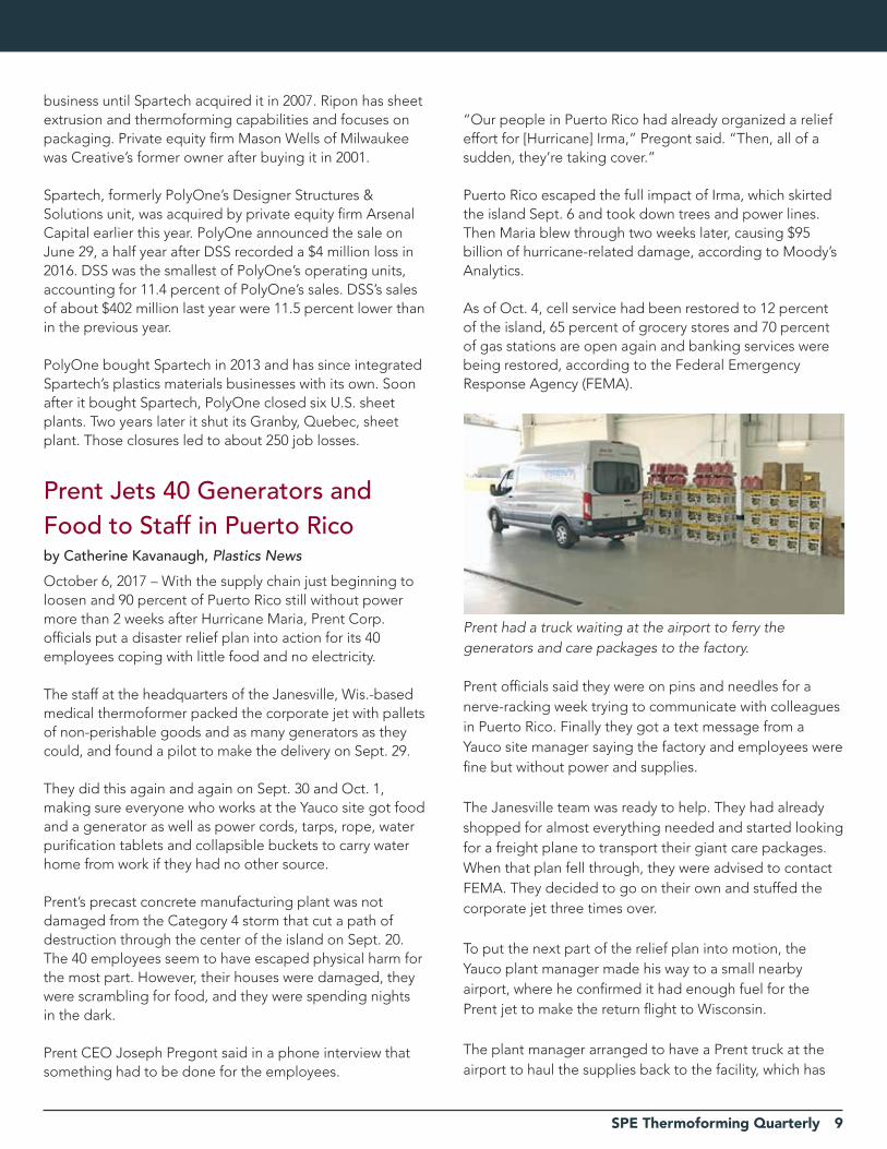
Prent Jets 40 Generators and Food to Staff in Puerto Ricoby Catherine Kavanaugh, Plastics News
October 6, 2017 – With the supply chain just beginning to loosen and 90 percent of Puerto Rico still without power more than 2 weeks after Hurricane Maria, Prent Corp. officials put a disaster relief plan into action for its 40 employees coping with little food and no electricity.
The staff at the headquarters of the Janesville, Wis.-based medical thermoformer packed the corporate jet with pallets of non-perishable goods and as many generators as they could, and found a pilot to make the delivery on Sept. 29.
They did this again and again on Sept. 30 and Oct. 1, making sure everyone who works at the Yauco site got food and a generator as well as power cords, tarps, rope, water purification tablets and collapsible buckets to carry water home from work if they had no other source.
Prent’s precast concrete manufacturing plant was not damaged from the Category 4 storm that cut a path of destruction through the center of the island on Sept. 20. The 40 employees seem to have escaped physical harm for the most part. However, their houses were damaged, they were scrambling for food, and they were spending nights in the dark.
Prent CEO Joseph Pregont said in a phone interview that something had to be done for the employees.
“Our people in Puerto Rico had already organized a relief effort for [Hurricane] Irma,” Pregont said. “Then, all of a sudden, they’re taking cover.”
Puerto Rico escaped the full impact of Irma, which skirted the island Sept. 6 and took down trees and power lines. Then Maria blew through two weeks later, causing $95 billion of hurricane-related damage, according to Moody’s Analytics.
As of Oct. 4, cell service had been restored to 12 percent of the island, 65 percent of grocery stores and 70 percent of gas stations are open again and banking services were being restored, according to the Federal Emergency Response Agency (FEMA).
Prent officials said they were on pins and needles for a nerve-racking week trying to communicate with colleagues in Puerto Rico. Finally they got a text message from a Yauco site manager saying the factory and employees were fine but without power and supplies.
The Janesville team was ready to help. They had already shopped for almost everything needed and started looking for a freight plane to transport their giant care packages. When that plan fell through, they were advised to contact FEMA. They decided to go on their own and stuffed the corporate jet three times over.
To put the next part of the relief plan into motion, the Yauco plant manager made his way to a small nearby airport, where he confirmed it had enough fuel for the Prent jet to make the return flight to Wisconsin.
The plant manager arranged to have a Prent truck at the airport to haul the supplies back to the facility, which has
Prent had a truck waiting at the airport to ferry the generators and care packages to the factory.

10 SPE Thermoforming Quarterly
Thermoforming In The News
been running all along on an auxiliary generator.“We had two trips in by the time we were told to call FEMA,” Pregont said. “We’re not a company that sits around and waits.”
The Janesville staff made sure to send baby formula and diapers in the second shipment of goods.
“We couldn’t cover everyone in Puerto Rico but we focused on our employees and got them things they needed,” Pregont said. “We put smiles on some faces.”
Prent’s Yauco plant has enough diesel fuel for generators to last a couple weeks. Company officials heard a nearby hospital is scheduled to have power restored next week and they hope surrounding customers get their electricity back, too.
Octal Investing $7.5 Million in Ohio Expansionby Jim Johnson, Plastics News
October 25, 2017 – Octal Extrusion Corp. is spending millions of dollars to expand operations in suburban Cincinnati, a project that will include installation of another extrusion line.
The Muscat, Oman-based company is known for its direct PET manufacturing approach, which allows the company to create sheets directly from molten resin. The process unique to Octal eliminates the need to create pellets that are then heated and extruded into sheet.
Octal’s facility in West Chester, Ohio, takes recycled PET flake from its thermoforming customers in North America and extrudes the material into new sheet. Initial construction at the facility that opened in 2015 included two extrusion lines.
“Cincinnati has really been a linchpin for growing our sheet business out of Oman,” said Joe Barenberg, chief revenue officer for Octal.
“We’re growing Cincinnati because the North American sheet business is growing very aggressively for us. We need that capacity that is coming on to continue to consume the flake that is coming back from our customers, which is increasing in volume on a steady basis,” he said.“Basically what you have is you have a spoke-and-wheel
strategy where you make product, ship it to the U.S. or elsewhere and you recycled it,” Octal CEO Nicholas Barakat added.
Equipment has been ordered and engineering is now taking place for the $7.5 million expansion that also includes additional material handling and storage capabilities.
“We’re hoping to get everything in mid-next year. We’re pushing as fast as we can,” Barenberg said.Octal originally took enough space in West Chester to allow for growth over time.
“We started with two machines, but we’re capable of expanding up to five machines. We have very large ambitions to grow in North America. And we wanted to make sure we weren’t space constrained,” he said.Barakat indicated current operations at the U.S. facility “are running flat out.”
“We have invested heavily in recycling capabilities, not only to recycle the flake ... but also to process it at a very high quality cost-effectively,” he said.
Octal expects to add about 20 workers with the new extrusion line at the facility that now employs about 50. Octal also sees the potential of adding a fourth extrusion line in the not-too-distant future, but there is no specific timetable at this point. A fourth extrusion line would add about another 20 jobs.
News of the Ohio growth comes as Octal is talking about plans to spend some $100 million to further expand the company overall, including the U.S. work. Barakat indicated the company expects to spend about $30 million on fixed assets and devote another $70 million in working capital to the effort.
Company expansion will include new equipment at the company’s production site in Salalah, Oman, as well. That’s where the company makes DPET sheet as well as PET resin.
While Octal’s business model is designed to supply PET sheet to customers that convert the material, the company also operates its own packaging operations in Riyadh, Saudi Arabia, for the dairy business. “This is for us to understand the market, understand how we deliver efficiencies to large users,” Barakat said about the converting business.
“It’s our belief that the DPET technology is really the

SPE Thermoforming Quarterly 11
You’ve known and trusted us as individual companies for
years. Now we’ve joined forces, operating as one, to bring
you turnkey solutions, more options, and better performance
so you can Run With Confidence.™
Introducing
Learn more at run-with-confidence.com
BETTER TOGETHER
12 SPE Thermoforming Quarterly
driver for thermoform packaging to expand in PET at the expense of other materials, generally,” Barenberg said.
The company looks at the inroads PET has made in the fiber business over the years and sees a similar opportunity for sheet. So Octal is working to “get the right collection of performance attributes to target very specific large scale markets that are probably currently in some other polymer.”
“There’s an overlapping to performance attributes which are prevalent to all of these polymers,” Barakat said. “They all do something. The question is, who does it best? So, there is a lot of substitution, even if it’s temporarily.
“What we don’t want is to have a bunch of really expensive, small market products. We’re about bringing good things to the market that change the value proposition for people in everyday life. And that’s only possible when we find clever ways to get performance at high-volume, low-cost manufacturing throughput,” Barenberg said.
Octal calls itself the largest PET resin and sheet producer at a single location.
Petcore Europe Reports on Thermoform Recycling Progressby Jared Paben, Resource Recycling, Inc.
November 3, 2017 – In Europe, thermoform packaging is using more and more RPET content, but impediments remain to efficient recycling of the thermoforms themselves. A workshop recently discussed the issues.
Trade group Petcore Europe reported on the results of a September workshop that provided updates to stakeholders on efforts to boost thermoform recycling. The event was held by PetCore’s Thermoforms Working Group, which was started in 2015 to increase recycling of the increasingly popular packaging format.
More and more post-consumer recovered PET is being recycled into thermoforms in Europe, according to the working group’s presentation. Specifically, in 2016, 490,000 metric tons of RPET was recycled into new thermoforms, surpassing the market for RPET bottles or fibers. Petcore estimated the average recycled content for PET thermoforms is now more than 45 percent.
Processing challengesReclaimers on both sides of the Atlantic note continuing
challenges with recycling thermoforms. A lot of it comes down to design: labels and glues. Those were the two main challenges identified by the Petcore working group. Labels are often too large and their glues can’t be easily removed, according to the summary, and soaker pads that are glued into the thermoforms are difficult to remove in recycling facilities.
The group also noted a challenge identified in a U.K. project, previously covered by Plastics Recycling Update: Washing and drying cycles break thermoform PET into more fines than is the case with bottle PET.
According to the Petcore summary, a test in France showed that recycling of monolayer PET trays together with bottles can work under certain conditions. The separation requires optical sorters that can distinguish between mono- and multi-layer packaging.
Another approach is to separate PET trays, and then further sort the monolayer thermoforms from the multi-layer ones.
“Dedicated recycling lines for PET thermoforms are under development,” according to the meeting summary.
In terms of end markets, Petcore pointed to new thermoforms. It noted that several studies have shown that washing, extrusion and solid stating will result in a good-quality material for use in colored applications, including grocery store food trays and agricultural trays.
The group also suggested incorporating thermoform PET into textiles, as well as compounding it for use in automotive applications. In terms of chemical recycling for difficult-to-recycle PET streams – thermoforms made of PET/PE or multilayer PET/PE/EVOH with greater oxygen-barrier properties – Petcore said there’s promise.
“Several startup companies are in the stage of scaling up their technologies and tests have shown that recycling of PET/PE and PET multilayer trays will work,” according to the summary. “However, the important question is if industry will be able to develop these technologies to an industrial and economically feasible scale.”
One company that has signed a deal to use its depolymerization process to recover PET from multilayer packaging is Loop Industries. The Montreal-area company recently agreed to purchased a site to scale up its technology. |
Thermoforming In The News

SPE Thermoforming Quarterly 13

14 SPE Thermoforming Quarterly
The Business of Thermoforming
Global Trends 2017By PLASTICS Industry Association
Editor’s Note: The following is taken from the recently released annual Global Trends report from PLASTICS (formerly SPI). It presents commentary and data on the state of the US plastics industry. Though thermoforming is not broken out in the data, the section under “equipment” highlights a trade deficit while other areas of the plastics supply chain show a surplus. The complete report can be downloaded at www.plasticsindustry.org.
The 2017 Global Trends report shows yet another decline in the U.S. plastics industry’s trade surplus, from $7.1 billion in 2015 to $4.7 billion in 2016. Much as it was last year, this decline was driven by a strengthening U.S. economy that depends heavily on imports to meet demand for plastic products.
This fact is borne out elsewhere in the report, most acutely in the apparent consumption figure, which is derived by combining imports and exports and subtracting that sum from the amount of total shipments made by the industry. In 2016, apparent consumption grew 1.8 percent which, as the report observes, reflects the greater use of U.S. plastics output domestically.
Additionally, that the U.S. plastics industry maintains its trade surplus at all makes it something of an anomaly among similarly situated manufacturing sectors. That it has done so for more than two decades consecutively, through a period in which the very nature of manufacturing and the global economy both changed drastically, illustrates just how durable the figure is, and speaks to the U.S. plastics industry’s continued impact on the international market.
The report also found in 2016 that Mexico and Canada remain the top destinations for exports from the U.S. plastics industry, with the industry exporting $15.4 billion to Mexico and $11.7 billion to Canada. The industry’s largest trade surplus is with Mexico at $10.7 billion, and its fifth-largest surplus is with Canada at $719 million.
This has been the case for the U.S. plastics industry in previous years, but it warrants special mention in this year’s edition of the report as the agreement that has
enabled these figures to benefit the U.S. plastics industry’s trade balances with its neighbors—the North American Free Trade Agreement (NAFTA)—is in the midst of renegotiation and, according to some observers, facing elimination if the new agreement does not meet the needs of American companies to some unspecified degree.
It has been noted before that the U.S. plastics industry maintains its trade surplus due to agreements like NAFTA, and other free trade agreements the U.S. maintains withother friendly nations. The revocation of NAFTA would have serious ramifications for the continued health of the U.S. plastics industry, and its renegotiation could as well, if undertaken without care.
That’s why PLASTICS has collaborated with its counterparts in Mexico and Canada—the Asociación Nacional de Industrias del Plástico A.C. (ANIPAC) and the Canadian Plastics Industry Association (CPIA)—to present NAFTA negotiators in all three countries with a set of priorities that the North American plastics industry agrees, as one, are worth revisiting in NAFTA’s renegotiation. These priorities were delivered to trade officials earlier in 2017 andthe three organizations remain involved in the renegotiation of this landmark agreement that benefits each country’s plastics industry and the millions of people they employ.
In its new section providing an outlook on specific export markets, the 2017 Global Trends report notes that “the U.S. has a powerful competitive advantage in resin product due to its scale, infrastructure and low cost raw materials. It would take a great deal of nationalism and protectionism to erase that advantage.”
Nonetheless, that the U.S. plastics industry is well positioned to weather a storm of protectionism does not mean that this storm need not be feared. Uncertainty as to the country’s commitment to its leading role in the expansion of free trade has already impacted the decision making in boardrooms across the globe. Should anti-trade rhetoric eventually transform into anti-trade policy, in the U.S. and in other nations across the developed world,the impacts on business and investment activity will only increase.
If nothing else, the 2017 Global Trends report, and the continuing example of the U.S. plastics industry, off er proof of the type of benefits free, open trade can confer
SPE Thermoforming Quarterly 15
to industries, and to the people they employ. There will always be room for improvement in domestic and international trade policy—always some way to make trade fairer, market access more open and consumer demand easier to meet from abroad. Even though a full retreat into protectionism is unlikely, to move in that direction would be a step backward for both the U.S. plastics industry and the global economy as a whole.
ExECUTIVE SUmmaryThis edition of the Plastics Industry Association’s (PLASTICS’) annual Global Trends study analyzes U.S. tradedata on an industry-wide and segment-specific basis for 2016.1 It is divided into five sections. Section I describesexports, imports and the trade balance for the industry and its four segments: resins, plastic products, molds and machinery. Section I also measures trade flows as a percentage of domestic shipments. Section II analyzesapparent consumption and market shares for the industry and its segments. Section III discusses trade in goodsthat contain resins and plastic products, labeled “contained trade” in this study. Section III also discusses the impact of contained trade on the industry’s overall trade position and measures the “true” consumption of resins and plastic products in the U.S. Section IV discusses the implications of this study’s findings for the industry.Finally, Section V presents an outlook for U.S. plastics industry exports, with emphasis on the top-five export-destination countries. The study’s key findings are:
INDUSTry-WIDE TrENDSn The industry’s trade surplus fell 33.7 percent to $4.7 billion in 2016 from $7.1 billion in 2015.n Industry exports fell 3.3 percent, and imports rose 0.8 percent.n Mexico and Canada remained the U.S. plastics industry’s largest export markets. In 2016, the industry exported$15.4 billion to Mexico and $11.7 billion to Canada.n The industry had its largest trade surplus with Mexico in 2016—$10.7 billion.n China is the industry’s third largest export market. However, the industry, overall, had its largest trade deficitwith China—$10.2 billion in 2016.n The estimated value of domestic shipments decreased by 2.2 percent in 2016, to $293.7 billion. Shipmentsfigures were depressed by low oil prices, which lowered the selling prices of plastics industry products,especially resin.
n Exports were at 19.5 percent of domestic shipments in 2016, down from 20.3 percent in 2015.n Reflecting the greater use of U.S. plastics output domestically, apparent consumption of plastics industrygoods grew 1.8 percent, from $284.0 billion in 2015 to $289.0 billion in 2016—faster than shipments growth.n “True” consumption includes all the resins and plastic products that U. S. residents consume, including thosethat are contained in imported goods. The “true” consumption growth rates computed in this study show that underlying U.S. plastics demand remains solid.
rESIN TrENDSn The U.S. resin industry had a $16.5 billion surplus in 2016, which was down 7.4 percent from the $17.9 billionsurplus in 2015, mostly because of lower resin prices. On a real, tonnage basis, the resin surplus decreasedonly 2.9 percent.n U.S. natural gas costs fell 4.0 percent in 2016, while the average crude oil price paid by U.S. refiners fell by agreater 16.1 percent. This further reduced the cost advantage of U.S. resin producers, which rely primarily ongas-based feedstocks. Nevertheless, overseas resin producers, which mostly use crude oil-based feedstocks,also became less advantaged because the sharp decline in the crude oil price paid by U.S. refiners benefitedtheir competitors in the U.S. that do rely on crude oil.n Resin exports decreased 4.9 percent in dollar terms, while imports decreased 1.9 percent.n The resin industry had a $6.0 billion surplus with Mexico, followed by a $2.7 billion surplus with China.n The resin industry had its largest trade deficit with Germany, at $0.9 billion.n Resin exports accounted for 37.0 percent of domestic shipments, while imports were 17.1 percent.n Apparent consumption of resins rose 4.2 percent, from $63.9 billion in 2015 to $66.6 billion in 2016. Domesticresin prices fell 4.7 percent, as measured by the Producer Price Index, which suggests that apparentconsumption increased 8.9 percent in real, tonnage terms.n U.S. resin producers held a 78.6 percent market share (percent of apparent consumption) in 2016, up from 77.3percent in 2015.n The estimated value of resins contained in exported goods was $19.5 billion, and the estimated value of resinscontained in imported goods was $43.9 billion, which meant that the segment had a $24.4 billion deficit incontained resin trade.
16 SPE Thermoforming Quarterly
The Business of Thermoforming
PLaSTIC PrODUCTS TrENDSn The country’s deficit in plastic products increased from $8.0 billion in 2015 to $9.0 billion in 2016, an increase of11.6 percent—mostly because of China’s exports, the higher-valued dollar and the improving U.S. economy.n Exports of plastic products fell by 1.5 percent, while imports grew 1.7 percent.n The U.S. had its largest plastic products surplus with Mexico, at $4.0 billion.n China accounted for the largest plastic products trade deficit, at $12.3 billion, up 2.4 percent from 2015.n Exports of plastic products were 12.0 percent of domestic shipments, and imports were 16.4 percent.n Apparent consumption of plastic products grew by 1.0 percent, from $210.6 billion in 2015 to $212.6 billionin 2016. As measured by the Producer Price Index, domestic plastic products prices fell 1.3 percent in 2016,suggesting that apparent consumption growth was 2.4 percent in real terms.n U.S. producers of plastic products held an 84.3 percent market share (percent of apparent consumption),down slightly from 84.4 percent 2015.n The estimated value of plastic products contained in exports was $25.1 billion, and the estimated valuecontained in imports was $51.5 billion, giving the U.S. a $26.4 billion deficit in contained plastic products trade.
mOLDS TrENDSn The U.S. moldmaking industry had a $1.2 billion trade deficit in 2016, which was 6.8 percent more than thedeficit in 2015.n Mold exports fell 1.9 percent, while imports rose 3.9 percent.n The U.S. moldmaking industry had its largest surplus with Mexico at $351 million. It had its largest deficit withCanada at $735 million.
n Exports of molds were 19.8 percent of domestic shipments, and imports were 62.2 percent.n Apparent consumption of molds for plastics rose 4.2 percent, from $3.9 billion in 2015 to $4.1 billion in 2016.n U.S. moldmakers held a 56.3 percent market share (percent of apparent consumption) in 2016, up from 56.1percent in 2015.
maCHINEry TrENDSn The U.S. plastics machinery industry registered a $1.7 billion trade deficit in 2016, a 2.7 percent increase from2015. The increase was due to strong domestic demand, along with a strong dollar that helped overseasproducers compete for that demand.n Exports were flat, and imports rose 1.5 percent.n The industry had its largest surplus with Mexico at $294 million, and its largest deficit with Germanyat $643 million.n Exports of machinery were 33.7 percent of domestic shipments, and imports were 75.1 percent.n Apparent consumption of plastics machinery rose 4.0 percent, from $5.5 billion in 2015 to $5.7 billion in 2016.Domestic shipments rose by 4.5 percent.n U.S. machinery producers held a 46.9 percent market share (percent of apparent consumption), up from 45.6percent in 2015. |
We Make Valve Automation Easy
Reduce Downtime & Maintenancewith Compact, Fast-Acting, High-Cycle Valves
Thermoforming OEM’s and factories all over the world areturning to Assured Automation’s Compact On/O� Valves toimprove their machines’ reliability and increase productivity.
For complete product information visit:
VA SeriesAngle Valves
VAX Series
/SPE
SPE Thermoforming Quarterly 17www.gncanada.com
New GN800 Form/Cut/Stack modelLatest addition to our line of GN thermoformers
Idealmachineforfood,medical andindustrialpackaging Inexpensivetooling Highefficiencyheaters Highclampingforceof75tons
inform,punch&cutstations In-mould-cutcapability
IdealmachineforPET/PEorPPmeat trayswithscraprateslowerthan18% IdealmachineforPETorPPlids In-mould-cuttoolingoffers100%
identicalparts Highefficiencyheaters Robotichandlingsystemincluded
World´sbestthermoformingmachine forbakerypackagingwith10-12% scraprates Lowelectricalconsumption Inexpensivetooling In-mould-cuttoolingoffers100%
identicalparts Robotichandlingavailable
GN Contact-Heat SeriesGreenest thermoformer
GN760 Plug-AssistLowest scrap % in the industry
Always thinking out of the box

18 SPE Thermoforming Quarterly
Industry Practice: From The Archives
Guillotine Shear Automically Cuts Thermoformed “Shots” From a Continuous WebAutomatic Guillotine Shears have replaced the machine operators who were stationed at the end of roll fed thermoformer’s, hand cutting formed sheets and stacking them for subseqent die cutting operations. Many thermoforming machines capable of operating at speeds greater than 10 cycles per minute are being throttled back so that the manual cut-off operatin can keep pace with the plastic forming. This expensive and non-productive procedure can be eliminated on any thermoformer by this self-contained modular guillotine shear.
Standard shear width are 29” and 40” with special sizes to 60” availlable on custom order. Formed plastic parts up to 6” high will clear the shear blades allowing a cutting speed to 20 cycles per minute.
Shop air pressure powers the shear with cutting taking place during the forming cycle. The blades are designed to operate so that their axis cross, similar to a scissors and tend to be self sharpening. Past experience with this type of shear indicates that many years of service is to be expected without maintenance.
Paper, cardboard and all thermoplastics ranging in thickness steel inlet and outlet troughs guide and support the moving web thru shear to the stacking pallets.
The guillotine is built on a modular frame which is mobile and can be readily disconnected and stored when not in use. The height of the shear can easily be adjusted to the thermoforming machine.
For further information contact Thermoform Tooling Co. Inc., 8 Gerardine Place, Spring Valley, N.Y. 10977, (914) E12-0497. |
Editor’s Note: Every so often, we dig into the archives to seek wisdom, to trace the evolution of our industry, or to have a chuckle at some of those fashions from the late 70s. This time, we uncovered a nugget from one of our very first issues. Thermoforming has come a long way since 1976, but unless you're grinding your scrap directly in-line, that accumulated skeleton still poses some tricky issues in a busy production environment!
SPE Thermoforming Quarterly 19
20 SPE Thermoforming Quarterly
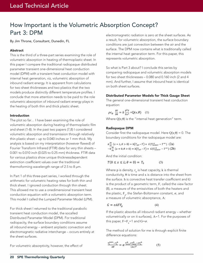
How Important is the Volumetric Absorption Concept?Part 3: DPM
Lead Technical Article
By Jim Throne, Consultant, Dunedin, FL
abstractThis is the third of a three-part series examining the role of volumetric absorption in heating of thermoplastic sheet. In this paper I compare the traditional radiopaque distributedparameter transient one-dimensional heat conduction model (DPM) with a transient heat conduction model with internal heat generation, viz, volumetric absorption of inbound radiant energy. It is apparent from calculations for two sheet thicknesses and two plastics that the two models produce distinctly different temperature profiles. I conclude that more attention needs to be paid to the role volumetric absorption of inbound radiant energy plays in the heating of both thin and thick plastic sheet.
IntroductionThe plot so far… I have been examining the role of volumetric absorption during heating of thermoplastic film and sheet (1-8). In the past two papers (7,8) I considered volumetric absorption and transmission through relatively thin plastic sheet – up to 0.040 inches or 1 mm thick. My analysis is based on my interpretation (however flawed) of Fourier Transform Infrared (FTIR) data for very thin sheets –0.001 to 0.010 inch (0.025 to 0.25 mm) thickness. FTIR data for various plastics show unique thicknessdependentextinction coefficient values over the traditional thermoforming wavelength range of 2.5 to 8 μm.
In Part 1 of this three-part series, I worked through the arithmetic for volumetric heating rates for both thin and thick sheet. I ignored conduction through thin sheet. This allowed me to use a onedimensional transient heat conduction equation with a volumetric absorption term. This model I called the Lumped Parameter Model (LPM).
For thick sheet I returned to the traditional parabolic transient heat conduction model, the socalledDistributed Parameter Model (DPM). For traditional radiopacity, the surface boundary conditions assume all inbound energy – ambient airplastic convection and electromagnetic radiative interchange – occurs entirely at the sheet surfaces.
For volumetric absorptivity, however, the effect of
electromagnetic radiation is zero at the sheet surfaces. As a result, for volumetric absorption, the surface boundary conditions are just convection between the air and the surface. The DPM now contains what is traditionally called the internal heat generation term. For this paper, this represents volumetric absorption.
So what is Part 3 about? I conclude this series by comparing radiopaque and volumetric absorption models for two sheet thicknesses – 0.080 and 0.160 inch (2 and 4 mm). And further, I assume that inbound heat is identical on both sheet surfaces.
Distributed Parameter models for Thick Gauge SheetThe general one-dimensional transient heat conduction equation:
Where Q(x;0) is the “internal heat generation” term.
radiopaque DPmConsider first the radiopaque model. Here Q(x;0) = 0. The boundary conditions for the radiopaque model are:
And the initial condition:
Where p is density, cp is heat capacity, k is thermal conductivity, 0 is time and x is distance into the sheet from the surface. h is convective heat transfer coefficient and G is the product of a geometric term, F, called the view factor (8), a measure of the emissivities of both the heaters and the plastic, Fg, the Stefan-Boltzmann constant, , anda measure of volumetric absorptance, A:
If the plastic absorbs all inbound radiant energy – whether volumetrically or on it surfaces), A=1. For the purposes of this paper, F=Fg=1 and G=.
The method of solution for me is through explicit finite difference equations:
SPE Thermoforming Quarterly 21
22 SPE Thermoforming Quarterly
Lead Technical Article
Where α is thermal diffusivity, α=k/pcp, i=1,2,3…N-1, and n=0,1,2,3… If I let r = , I can write equation 5 as:
As another aside, the term r is often called the differential Fourier number, ΔFo.
I now write the boundary condition at x=0 as a forward difference equation
And the boundary condition at x=L as a backward difference equation:
Note that f(…) in these equations is the differential form for that in equation 2. The fourthpower radiant energy term prevents me from writing the surface temperatures in explicit terms of known variables and parameters. I can either iterate the equations for T0 and TN for all n’s or I canapproximate the radiant energy terms as follows:
The initial condition is for 1 = I = N-1.
Okay, I’m now ready to solve the traditional radiopaque equation using the physical parameters of Table 1.
Volumetric absorption DPmIn order to rework the radiopaque model– equations 16, 17a, 17b, and 3, the initial condition– I need to determine what changes are needed to include the volumetric absorption terms. Again I refer back to (1).
The functional equation is:
Where q(x;0) is the volumetric absorption flux, viz:
And Q is the total volumetric heat absorption. As I note in (1), if is the extinction coefficient from the Beer-Lambert-Bouguer equation, I can write the volumetric absorption at surface x=0 as:
The flux is the rate of change of Q(0;0) with respect to position x:
The volumetric absorption at surface x=L is:
And the flux is the rate of change of Q(x;0) with respect to position x=L:
The total flux then is
And if the inbound radiative energy is uniform on both sheet surfaces, this equation can be written as:
Where G is the same term as given in the earlier equation. Keep in mind that is still a fourth-power term imbedded in the differential or difference equation. Of course, I need to also difference equation (12).
The functional equation becomes:
As a check, I slice the slab into i=Δx/L elements. When i=0, T=To. When i=N or x=L, T=TN. When i Δx=0, the parens at the right is (1-e -L), i.e., whatever energy is still being transmitted through the plastic from the x=L surface. And when i Δx=L, the parens at the right is (1-e -L), being the energy transmitted through the plastic from x=0. Check and double-check.
The boundary conditions for the volumetric absorption DPM are:
In other words, the convective terms are all that remain at the surfaces of the sheet. The initial sheet temperature is given as equation (3).
As before, I consider the fourth-power of the heater temperature to overwhelm that of the sheet and so, rather than to iterate the sheet temperature, I chose to use the earlier value when solving the difference equation (13).
SPE Thermoforming Quarterly 23
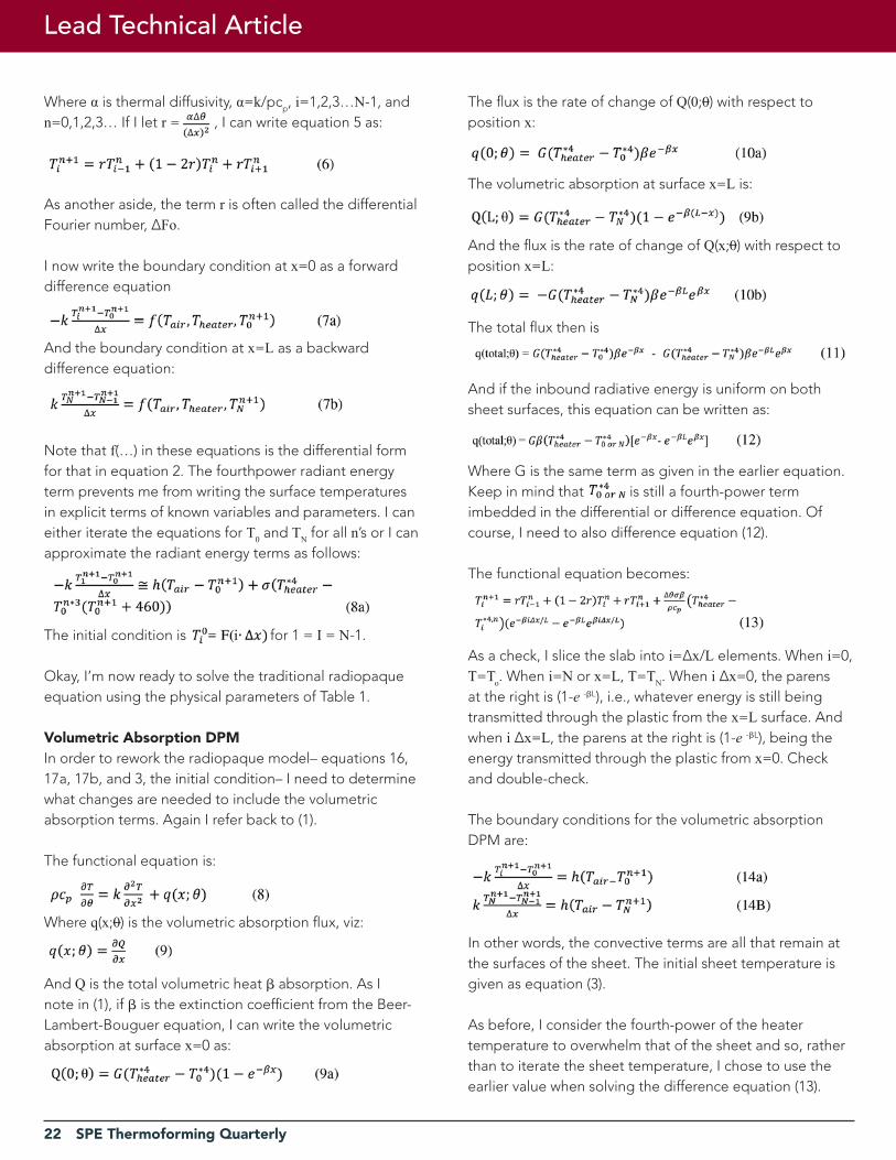
Comparison of modelsFor this exercise, I compare the transient heating DPM models of polystyrene for 0.080-inch and 0.160-inch sheet. The even figures are for the radiopaque models. The odd figures are for the volumetric absorption models.
Figure 1. 0.080-inch PS RadiopaqueBlue: x=0. Red: x=0.005 in. Green: x=0.010 in.Black: x=0.015 in. Grey: x=0.040 centerline.
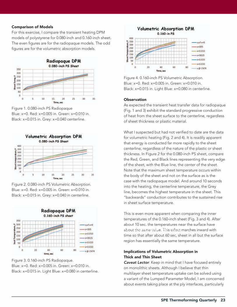
Figure 2. 0.080-inch PS Volumetric Absorption.Blue: x=0. Red: x=0.005 in. Green: x=0.010 in.Black: x=0.015 in. Grey: x=0.040 in centerline.
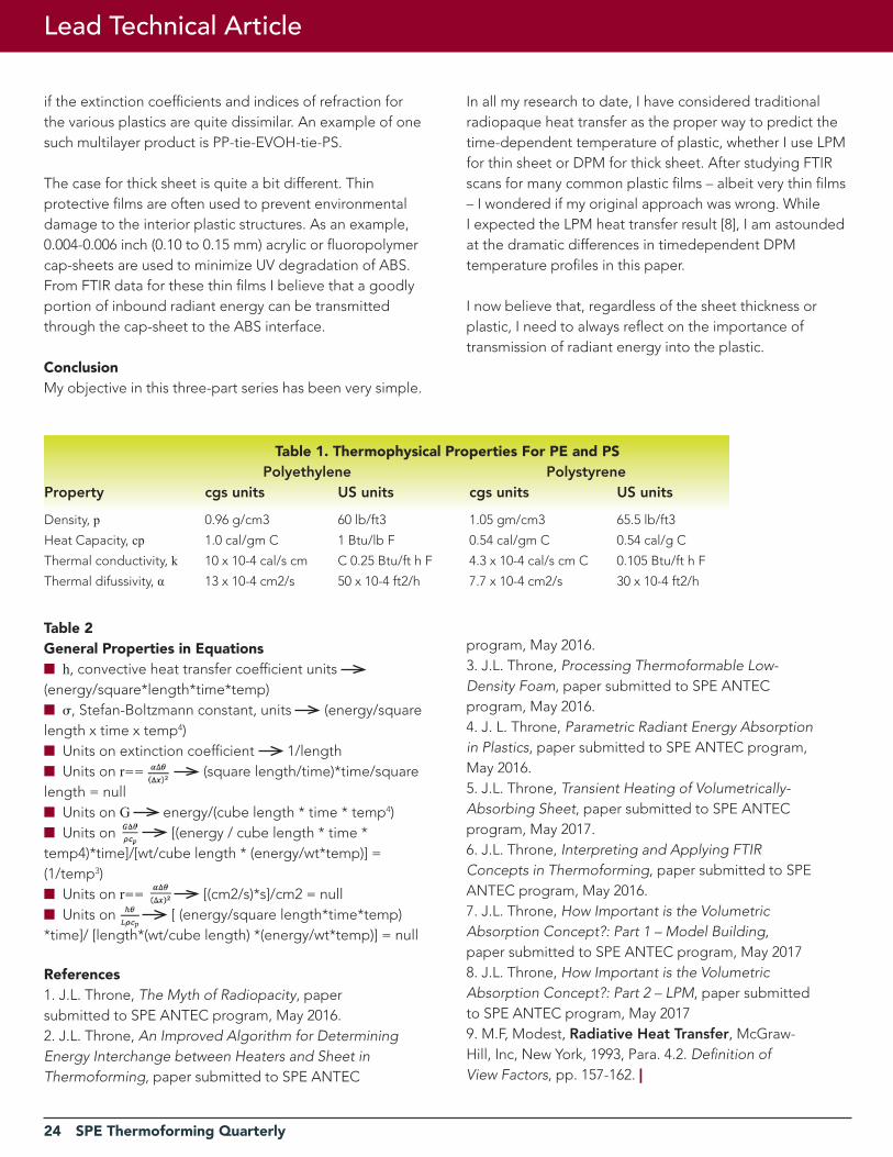
Figure 3. 0.160-inch PS Radiopaque.Blue: x=0. Red: x=0.005 in. Green: x=0.010 in.Black: x=0.015 in. Light Blue: x=0.080 in centerline.
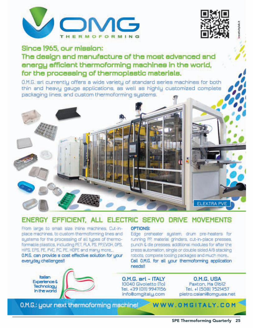
Figure 4. 0.160-inch PS Volumetric Absorption.Blue: x=0. Red: x=0.005 in. Green: x=0.010 in.Black: x=0.015 in. Light Blue: x=0.080 in centerline.
ObservationAs expected the transient heat transfer data for radiopaque (Fig. 1 and 3) exhibit the standard progressive conduction of heat from the sheet surface to the centerline, regardless of sheet thickness or plastic material.
What I suspected but had not verified to date are the data for volumetric heating (Fig. 2 and 4). It is readily apparent that energy is conducted far more rapidly to the sheet centerline, regardless of the nature of the plastic or sheet thickness. In Figure 2 for the 0.080-inch PS sheet, compare the Red, Green, and Black lines representing the very edge of the sheet, with the Blue line, the center of the sheet. Note that the maximum sheet temperature occurs withinthe body of the sheet and not on the surface as is the case with the radiopaque model. And around 10 seconds into the heating, the centerline temperature, the Grey line, becomes the highest temperature in the sheet. This “backwards” conduction contributes to the sustained rise in sheet surface temperature.
This is even more apparent when comparing the inner temperatures of the 0.160-inch sheet (Fig. 3 and 4). After about 10 sec. the temperatures near the surface have about the same value. This effect marches inward with time so that after about 60 sec, sheet in all but the surface region has essentially the same temperature.
Implications of Volumetric absorption in Thick and Thin SheetCaveat Lector: Keep in mind that I have focused entirely on monolithic sheets. Although I believe that thin multilayer sheet temperature uptake can be solved using a variant of the Lumped Parameter Model, I am concerned about events taking place at the ply interfaces, particularly
Lead Technical Article
24 SPE Thermoforming Quarterly
if the extinction coefficients and indices of refraction forthe various plastics are quite dissimilar. An example of one such multilayer product is PP-tie-EVOH-tie-PS.
The case for thick sheet is quite a bit different. Thin protective films are often used to prevent environmental damage to the interior plastic structures. As an example, 0.004-0.006 inch (0.10 to 0.15 mm) acrylic or fluoropolymer cap-sheets are used to minimize UV degradation of ABS. From FTIR data for these thin films I believe that a goodlyportion of inbound radiant energy can be transmittedthrough the cap-sheet to the ABS interface.
ConclusionMy objective in this three-part series has been very simple.
In all my research to date, I have considered traditional radiopaque heat transfer as the proper way to predict the time-dependent temperature of plastic, whether I use LPM for thin sheet or DPM for thick sheet. After studying FTIR scans for many common plastic films – albeit very thin films – I wondered if my original approach was wrong. WhileI expected the LPM heat transfer result [8], I am astounded at the dramatic differences in timedependent DPM temperature profiles in this paper.
I now believe that, regardless of the sheet thickness or plastic, I need to always reflect on the importance of transmission of radiant energy into the plastic.
Table 1. Thermophysical Properties For PE and PS Polyethylene PolystyreneProperty cgs units US units cgs units US units
Density, p 0.96 g/cm3 60 lb/ft3 1.05 gm/cm3 65.5 lb/ft3
Heat Capacity, cp 1.0 cal/gm C 1 Btu/lb F 0.54 cal/gm C 0.54 cal/g C
Thermal conductivity, k 10 x 10-4 cal/s cm C 0.25 Btu/ft h F 4.3 x 10⁻⁴ cal/s cm C 0.105 Btu/ft h F
Thermal difussivity, α 13 x 10-4 cm2/s 50 x 10-4 ft2/h 7.7 x 10⁻⁴ cm2/s 30 x 10-4 ft2/h
Table 2General Properties in Equationsn h, convective heat transfer coefficient units
(energy/square*length*time*temp)n , Stefan-Boltzmann constant, units (energy/squarelength x time x temp4)n Units on extinction coefficient 1/lengthn Units on r== (square length/time)*time/squarelength = nulln Units on G energy/(cube length * time * temp4)n Units on [(energy / cube length * time *temp4)*time]/[wt/cube length * (energy/wt*temp)] = (1/temp3)n Units on r== [(cm2/s)*s]/cm2 = nulln Units on [ (energy/square length*time*temp) *time]/ [length*(wt/cube length) *(energy/wt*temp)] = null
references1. J.L. Throne, The Myth of Radiopacity, papersubmitted to SPE ANTEC program, May 2016.2. J.L. Throne, An Improved Algorithm for DeterminingEnergy Interchange between Heaters and Sheet inThermoforming, paper submitted to SPE ANTEC
program, May 2016.3. J.L. Throne, Processing Thermoformable Low-Density Foam, paper submitted to SPE ANTECprogram, May 2016.4. J. L. Throne, Parametric Radiant Energy Absorptionin Plastics, paper submitted to SPE ANTEC program,May 2016.5. J.L. Throne, Transient Heating of Volumetrically-Absorbing Sheet, paper submitted to SPE ANTECprogram, May 2017.6. J.L. Throne, Interpreting and Applying FTIRConcepts in Thermoforming, paper submitted to SPEANTEC program, May 2016.7. J.L. Throne, How Important is the VolumetricAbsorption Concept?: Part 1 – Model Building,paper submitted to SPE ANTEC program, May 20178. J.L. Throne, How Important is the VolumetricAbsorption Concept?: Part 2 – LPM, paper submittedto SPE ANTEC program, May 20179. M.F, Modest, Radiative Heat Transfer, McGraw-Hill, Inc, New York, 1993, Para. 4.2. Definition ofView Factors, pp. 157-162. |
Lead Technical Article
SPE Thermoforming Quarterly 25
26 SPE Thermoforming Quarterly
Process Optimization of Single-Screw Extrusion Systems for Polyolefin Resins
Lead Technical Article
By Mark A. Spalding and Qian Gou, The Dow Chemical Company, Midland, MI
This paper is reproduced here with the kind permission of the SPE Extrusion Division.
abstractMany existing extruders running polyethylene (PE) resins can be optimized to operate at higher production rates and also with higher qualities by the mitigation of gels. This paper provides an assessment process where the extruder is studied for potential rate increases and quality improvements. It is recommended that such an assessment be made prior to purchasing new screws or when a line is close to becoming fully utilized and more product is required.
IntroductionThe maximum profitability of any extrusion line will occur when the line is fully utilized and running at the highest rate and maximum yield. Moreover, if the line is fully utilized (running at maximum capacity) and additional sales are possible, a rate increase for a line has the potential of meeting market demands while delaying the capital cost of a new line for a few years. A yield increase will also provide an increase in saleable products.
Many processes that are profitable today are operating at less than optimal conditions. In many cases, items such as the screw and barrel have worn to a point where the flight clearances have increased, causing lower specific rates, higher discharge temperatures, and lower heat transfer coefficients at the barrel wall. In most cases, the screw must rotate at a higher speed to maintain a constant rate. When replacing screws, an assessment of the current process should be made by an extrusion expert before the replacement screw is ordered, especially if the process has changed or the line is fully utilized. The assessment would provide the converter knowledge on whether changes to the screw design could provide economic gains through increased rate, yield, and quality.
In other cases, screw technology that is 30 years old continues to be used even though other process changes have occurred. For example, a screw design was set years
ago for a large diameter extruder and optimized to run a low density polyethylene (LDPE) resin. When the screw was installed it likely operated properly, producing at high rate, at the proper discharge temperature and pressure, and with relatively low levels of gels. When the screw became worn, additional screws were fabricated with the same design. As the business evolved, the line was converted to a linear low density polyethylene (LLDPE) resin product. After a short period of time, the film product experienced a higher level of crosslinked gels. For this case, the long residence time regions in the screw were not long enough to degrade the LDPE resin, but the more thermally sensitive LLDPE resin exhibited a level of crosslinked gels in the product. The higher level of gels decreased the value of the film product and reduced the capacity of the line due to bubble breaks.
Lastly, some designers do not understand all the fundamentals of extrusion and thus are not capable of designing a screw with optimal performance for rate and quality. In many cases, the screw that is designed is based on a library of other screws that have worked well in the past for similar processes. Often, the next screw that is fabricated will contain the same flaws that exist in the current screws.
Many screws are designed to operate at a target rate and discharge temperature. These designs typically work well within the target criteria. But as business demands increase and the lines are operated at higher rates, the discharge temperatures increase until the product quality is out of specification. In these cases, the only way to obtain a rate increase is to design a process that discharges at a lower temperature. One simple method is to place the barrel sections that cover the metering section of the screw in a cooling mode [1]. A moderate level of cooling can provide a small incremental reduction in the extrudate temperature [2]. After the discharge temperature is decreased, the screw speed can be increased for an increase in rate. This cooling mode method will often provide small rate increases if the screw and barrel are not worn. Higher rate increases can sometimes be obtained by optimizing the screw design. For example, three screw deign cases are provided in Table 1. In each case, a new screw was designed and fabricated such that a lower level of energy
SPE Thermoforming Quarterly 27
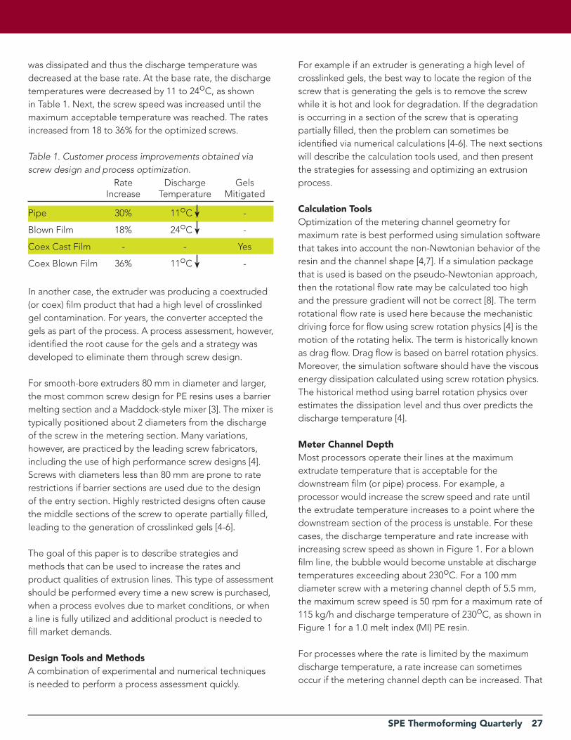
was dissipated and thus the discharge temperature was decreased at the base rate. At the base rate, the discharge temperatures were decreased by 11 to 24oC, as shown in Table 1. Next, the screw speed was increased until the maximum acceptable temperature was reached. The rates increased from 18 to 36% for the optimized screws.
Table 1. Customer process improvements obtained via screw design and process optimization. Rate Discharge Gels Increase Temperature Mitigated
Pipe 30% 11oC -
Blown Film 18% 24oC -
Coex Cast Film - - Yes
Coex Blown Film 36% 11oC -
In another case, the extruder was producing a coextruded (or coex) film product that had a high level of crosslinked gel contamination. For years, the converter accepted the gels as part of the process. A process assessment, however, identified the root cause for the gels and a strategy was developed to eliminate them through screw design.
For smooth-bore extruders 80 mm in diameter and larger, the most common screw design for PE resins uses a barrier melting section and a Maddock-style mixer [3]. The mixer is typically positioned about 2 diameters from the discharge of the screw in the metering section. Many variations, however, are practiced by the leading screw fabricators, including the use of high performance screw designs [4]. Screws with diameters less than 80 mm are prone to rate restrictions if barrier sections are used due to the design of the entry section. Highly restricted designs often cause the middle sections of the screw to operate partially filled, leading to the generation of crosslinked gels [4-6].
The goal of this paper is to describe strategies and methods that can be used to increase the rates and product qualities of extrusion lines. This type of assessment should be performed every time a new screw is purchased, when a process evolves due to market conditions, or when a line is fully utilized and additional product is needed to fill market demands.
Design Tools and methodsA combination of experimental and numerical techniques is needed to perform a process assessment quickly.
For example if an extruder is generating a high level of crosslinked gels, the best way to locate the region of the screw that is generating the gels is to remove the screw while it is hot and look for degradation. If the degradation is occurring in a section of the screw that is operating partially filled, then the problem can sometimes be identified via numerical calculations [4-6]. The next sections will describe the calculation tools used, and then present the strategies for assessing and optimizing an extrusion process.
Calculation ToolsOptimization of the metering channel geometry for maximum rate is best performed using simulation software that takes into account the non-Newtonian behavior of the resin and the channel shape [4,7]. If a simulation package that is used is based on the pseudo-Newtonian approach, then the rotational flow rate may be calculated too high and the pressure gradient will not be correct [8]. The term rotational flow rate is used here because the mechanistic driving force for flow using screw rotation physics [4] is the motion of the rotating helix. The term is historically known as drag flow. Drag flow is based on barrel rotation physics. Moreover, the simulation software should have the viscous energy dissipation calculated using screw rotation physics. The historical method using barrel rotation physics over estimates the dissipation level and thus over predicts the discharge temperature [4].
meter Channel DepthMost processors operate their lines at the maximum extrudate temperature that is acceptable for the downstream film (or pipe) process. For example, a processor would increase the screw speed and rate until the extrudate temperature increases to a point where the downstream section of the process is unstable. For these cases, the discharge temperature and rate increase with increasing screw speed as shown in Figure 1. For a blown film line, the bubble would become unstable at discharge temperatures exceeding about 230oC. For a 100 mm diameter screw with a metering channel depth of 5.5 mm, the maximum screw speed is 50 rpm for a maximum rate of 115 kg/h and discharge temperature of 230oC, as shown in Figure 1 for a 1.0 melt index (MI) PE resin.
For processes where the rate is limited by the maximum discharge temperature, a rate increase can sometimes occur if the metering channel depth can be increased. That

28 SPE Thermoforming Quarterly
is, when the channel depth is increased the specific rate will typically increase, shear rate and viscous dissipation will decrease, and the discharge temperature will decrease at the base rate, as shown in Figure 2. For this figure, the rate was held constant at 150 kg/h and the screw speed was adjusted to maintain a discharge pressure of 30 MPa. More specifically, the original screw with a metering channel depth of 5.5 mm would operate at a specific rate 2.30 kg/(h rpm) and a discharge temperature of 236oC at a rate of 150 kg/h. Increasing the channel depth to 7.5 mm would increase the specific rate to 2.75 kg/(h rpm) and decrease the discharge temperature to 221oC. Since the rate was held constant, the screw speed was decreased from 65 to 55 rpm when the channel depth was increased from 5.5 to 7.5 mm.
Optimization of a screw by increasing the metering channel depth will cause the torque to increase on the screw and the motor, and the designer must make sure that enough
Figure 1. Rate and discharge temperature for a 100 mm diameter screw with a metering channel depth of 5.5 mm.
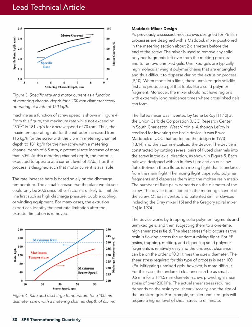
Figure 2. Specific rate and discharge temperature as a function of metering channel depth for a 100 mm diameter screw operating at a rate of 150 kg/h.
torque is available. The increased torque will be observed as an increase in the motor current. The energy and motor current required for a process can be estimated from the name plate data on the motor and gear box and the processing data. The data for the motor include power rating, maximum base speed, and the maximum current (at full power). The maximum screw speed is then calculated by dividing the motor speed by the gear box reduction and the belt sheave reduction (if used). The specific energy inputted by the screw to the resin is then estimated as follows:
(1)
(2)
where P is the power that is dissipated in kW, Pmax is the name-plate power (kW) for the motor, A is the motor current observed during the extrusion, Amax is the name-plate motor current at full load, N is the screw speed (rpm) during extrusion, and Nmax is the maximum screw speed (rpm) that the extruder is capable of running at the base motor speed. After the power is computed, the specific energy inputted to the resin from the screw, E, in J/g is calculated using Equation (2) and the extrusion rate, Q, in kg/h. The calculation neglects the inefficiencies for converting electrical power to mechanical power and the power factor.
For the extrusion of the 1.0 MI PE resin, a specific energy of about 800 J/g is required. The 100 mm diameter extruder is equipped with a 100 kW motor. The gearbox and motor are such that a maximum screw speed of 132 rpm is obtained at the base motor speed. For this motor-drive configuration and specific energy consumption, the specific rate and motor current level is shown as a function of metering channel depth in Figure 3. The motor current levels for the 5.5 and 7.5 mm deep metering channels are 68 and 81% of the maximum, respectively. As expected, the motor current used for the process will increase when the depth of the metering channel is increased. If an extruder is limited by motor current, a rate increase via increasing the channel depth of the metering section cannot be accomplished.
A new screw was designed for the 100 mm diameter extruder using a screw with a metering channel depth of 6.5 mm. The rate and discharge temperature for the
Lead Technical Article
SPE Thermoforming Quarterly 29
30 SPE Thermoforming Quarterly
machine as a function of screw speed is shown in Figure 4. From this figure, the maximum rate while not exceeding 230oC is 181 kg/h for a screw speed of 70 rpm. Thus, the maximum operating rate for the extruder increased from 115 kg/h for the screw with the 5.5 mm metering channel depth to 181 kg/h for the new screw with a metering channel depth of 6.5 mm, a potential rate increase of more than 50%. At this metering channel depth, the motor is expected to operate at a current level of 75%. Thus the process is designed such that motor current is available.
The rate increase here is based solely on the discharge temperature. The actual increase that the plant would see could only be 20% since other factors are likely to limit the line first such as high discharge pressure, bubble cooling, or winding equipment. For many cases, the extrusion expert can identify the next rate limitation after the extruder limitation is removed.
Figure 3. Specific rate and motor current as a function of metering channel depth for a 100 mm diameter screw operating at a rate of 150 kg/h.
Figure 4. Rate and discharge temperature for a 100 mm diameter screw with a metering channel depth of 6.5 mm.
maddock mixer DesignAs previously discussed, most screws designed for PE film processes are designed with a Maddock mixer positioned in the metering section about 2 diameters before the end of the screw. The mixer is used to remove any solid polymer fragments left over from the melting process and to remove unmixed gels. Unmixed gels are typically high molecular weight polymer chains that are entangled and thus difficult to disperse during the extrusion process [9,10]. When made into films, these unmixed gels solidify first and produce a gel that looks like a solid polymer fragment. Moreover, the mixer should not have regions with extremely long residence times where crosslinked gels can form.
The fluted mixer was invented by Gene LeRoy [11,12] at the Union Carbide Corporation (UCC) Research Center in South Charleston, West Virginia. Although LeRoy is credited for inventing the basic device, it was Bruce Maddock of UCC that perfected the design in 1973 [13,14] and then commercialized the device. The device is constructed by cutting several pairs of fluted channels into the screw in the axial direction, as shown in Figure 5. Each pair was designed with an in-flow flute and an out-flow flute. Between these flutes is a mixing flight that is undercut from the main flight. The mixing flight traps solid polymer fragments and disperses them into the molten resin matrix. The number of flute pairs depends on the diameter of the screw. The device is positioned in the metering channel of the screw. Others invented and patented similar devices including the Dray mixer [15] and the Gregory spiral mixer [16] in 1974.
The device works by trapping solid polymer fragments and unmixed gels, and then subjecting them to a one-time, high shear stress field. The shear stress field occurs as the resin is flowing across the undercut mixing flight. For PE resins, trapping, melting, and dispersing solid polymer fragments is relatively easy and the undercut clearance can be on the order of 0.01 times the screw diameter. The shear stress required for this type of process is near 100 kPa. Mitigating unmixed gels, however, is more difficult. For this case, the undercut clearance can be as small as 0.5 mm for a 114.5 mm diameter screw, providing a shear stress of over 200 kPa. The actual shear stress required depends on the resin type, shear viscosity, and the size of the unmixed gels. For example, smaller unmixed gels will require a higher level of shear stress to eliminate.
Lead Technical Article
SPE Thermoforming Quarterly 31
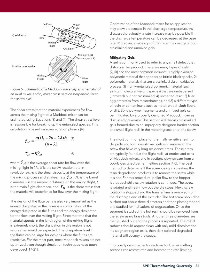
The shear stress that the material experiences for flow across the mixing flight of a Maddock mixer can be estimated using Equations (3) and (4). The shear stress level is responsible for breaking up the entangled species. This calculation is based on screw rotation physics [4].
(3)
(4)
where is the average shear rate for flow over the mixing flight in 1/s, N is the screw rotation rate in revolutions/s, is the shear viscosity at the temperature of the mixing process and at shear rate , Db is the barrel diameter, u is the undercut distance on the mixing flight, is the main flight clearance, and is the shear stress that the material will experience for flow over the mixing flight.
The design of the flute pairs is also very important as the energy dissipated in the mixer is a combination of the energy dissipated in the flutes and the energy dissipated for the flow over the mixing flight. Since the time that the material spends in the land region of the mixing flight is extremely short, the dissipation in this region is not as great as would be expected. The dissipation level in the flutes can be large for designs where the flutes are restrictive. For the most part, most Maddock mixers are not optimized even though simulation techniques have been developed [17-21].
Figure 5. Schematic of a Maddock mixer [4]: a) schematic of an axial mixer, and b) mixer cross section perpendicular to the screw axis.
Optimization of the Maddock mixer for an application may allow a decrease in the discharge temperature. As discussed previously, a rate increase may be possible if the discharge temperature can be decreased at the base rate. Moreover, a redesign of the mixer may mitigate both crosslinked and unmixed gels.
mitigating GelsA gel is commonly used to refer to any small defect that distorts a film product. There are many types of gels [9,10] and the most common include: 1) highly oxidized polymeric material that appears as brittle black specks, 2) polymeric materials that are crosslinked via an oxidative process, 3) highly-entangled polymeric material (such as high molecular weight species) that are undispersed (unmixed) but not crosslinked, 4) unmelted resin, 5) filler agglomerates from masterbatches, and 6) a different type of resin or contaminant such as metal, wood, cloth fibers, or dirt. Solid polymer fragments and unmixed gels can be mitigated by a properly designed Maddock mixer as discussed previously. This section will discuss crosslinked gels formed due to an improperly designed barrier section and small flight radii in the metering section of the screw.
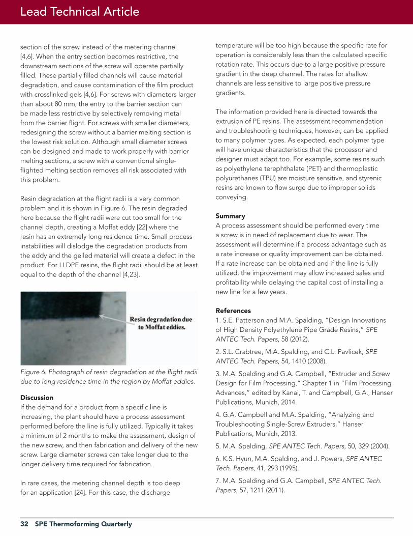
The most common place for thermally sensitive resin to degrade and form crosslinked gels is in regions of the screw that have very long residence times. These areas are typically found at the flight radii, at entries and exits of Maddock mixers, and in sections downstream from a poorly designed barrier melting section [4,6]. The best method to determine if the screw design is creating the resin degradation products is to remove the screw while it is hot. For this procedure, pellet flow to the hopper is stopped while screw rotation is continued. The screw is rotated until resin flow out the die stops. Next, screw rotation is stopped and the transfer line is removed from the discharge end of the extruder. The hot screw should be pushed out about three diameters and then photographed and studied for indications of degradation. Once the segment is studied, the hot resin should be removed from the screw using brass tools. Another three diameters are then pushed out and the process is repeated. The metal surfaces should appear clean with only mild discoloration. If a stagnant region exits, then dark colored degraded material will occupy the space.
Improperly designed entry sections for barrier melting sections can restrict rate and become the rate limiting
32 SPE Thermoforming Quarterly
section of the screw instead of the metering channel [4,6]. When the entry section becomes restrictive, the downstream sections of the screw will operate partially filled. These partially filled channels will cause material degradation, and cause contamination of the film product with crosslinked gels [4,6]. For screws with diameters larger than about 80 mm, the entry to the barrier section can be made less restrictive by selectively removing metal from the barrier flight. For screws with smaller diameters, redesigning the screw without a barrier melting section is the lowest risk solution. Although small diameter screws can be designed and made to work properly with barrier melting sections, a screw with a conventional single-flighted melting section removes all risk associated with this problem.
Resin degradation at the flight radii is a very common problem and it is shown in Figure 6. The resin degraded here because the flight radii were cut too small for the channel depth, creating a Moffat eddy [22] where the resin has an extremely long residence time. Small process instabilities will dislodge the degradation products from the eddy and the gelled material will create a defect in the product. For LLDPE resins, the flight radii should be at least equal to the depth of the channel [4,23].
DiscussionIf the demand for a product from a specific line is increasing, the plant should have a process assessment performed before the line is fully utilized. Typically it takes a minimum of 2 months to make the assessment, design of the new screw, and then fabrication and delivery of the new screw. Large diameter screws can take longer due to the longer delivery time required for fabrication.
In rare cases, the metering channel depth is too deep for an application [24]. For this case, the discharge
Figure 6. Photograph of resin degradation at the flight radii due to long residence time in the region by Moffat eddies.
temperature will be too high because the specific rate for operation is considerably less than the calculated specific rotation rate. This occurs due to a large positive pressure gradient in the deep channel. The rates for shallow channels are less sensitive to large positive pressure gradients.
The information provided here is directed towards the extrusion of PE resins. The assessment recommendation and troubleshooting techniques, however, can be applied to many polymer types. As expected, each polymer type will have unique characteristics that the processor and designer must adapt too. For example, some resins such as polyethylene terephthalate (PET) and thermoplastic polyurethanes (TPU) are moisture sensitive, and styrenic resins are known to flow surge due to improper solids conveying.
SummaryA process assessment should be performed every time a screw is in need of replacement due to wear. The assessment will determine if a process advantage such as a rate increase or quality improvement can be obtained. If a rate increase can be obtained and if the line is fully utilized, the improvement may allow increased sales and profitability while delaying the capital cost of installing a new line for a few years.
references1. S.E. Patterson and M.A. Spalding, “Design Innovations of High Density Polyethylene Pipe Grade Resins,” SPE ANTEC Tech. Papers, 58 (2012).
2. S.L. Crabtree, M.A. Spalding, and C.L. Pavlicek, SPE ANTEC Tech. Papers, 54, 1410 (2008).
3. M.A. Spalding and G.A. Campbell, “Extruder and Screw Design for Film Processing,“ Chapter 1 in “Film Processing Advances,” edited by Kanai, T. and Campbell, G.A., Hanser Publications, Munich, 2014.
4. G.A. Campbell and M.A. Spalding, “Analyzing and Troubleshooting Single-Screw Extruders,” Hanser Publications, Munich, 2013.
5. M.A. Spalding, SPE ANTEC Tech. Papers, 50, 329 (2004).
6. K.S. Hyun, M.A. Spalding, and J. Powers, SPE ANTEC Tech. Papers, 41, 293 (1995).
7. M.A. Spalding and G.A. Campbell, SPE ANTEC Tech. Papers, 57, 1211 (2011).
Lead Technical Article

SPE Thermoforming Quarterly 33
8. M.A. Spalding and G.A. Campbell, SPE ANTEC Tech. Papers, 54, 262 (2008).
9. T.I. Butler, “Gel Troubleshooting,” in “Film Extrusion Manual,” Chapter 19, Edited by T.I. Butler TAPPI Press, Atlanta, GA, 2005.
10. M.A. Spalding, E. Garcia-Meitin, S.L. Kodjie, and G.A. Campbell, SPE ANTEC Tech. Papers, 59, 1205 (2013).
11. G. LeRoy, US Patent 3,486,192 (December 30, 1969).
12. P. Andersen, C-K. Shih, M.A. Spalding, M.D. Wetzel, and T.W. Womer, SPE ANTEC Tech. Papers, 55, 668 (2009).
13. B.H. Maddock, US Patent 3,730,492 (1973).
14. B.H. Maddock, US Patent 3,756,574 (1973).
15. R.F. Dray, US Patent 3,788,612 (1974).
16. R.B. Gregory, US Patent 3,788,614 (1974).
17. C.D. Han, K.Y. Lee, and N.C. Wheeler, Polym. Eng. Sci., 31, 818 (1991).
18. Y. Wang and C.C. Tsay, Polym. Eng. Sci., 36, 645 (1996).
19. C. Klason, V.V. Jinescu, and I. Postoaca, Int. Polym. Process., 15, 3 (2000).
20. G. Zitzenbacher, R. Karlbauer, and H. Thiel, Int. Polym. Process., 22, 73 (2007).
21. P. Kubik, J. Vlcek, C. Tzoganakis, and L. Miller, Polym. Eng. Sci., 52, 1232 (2012).
22. H.K. Moffat, J. Fluid Mech. 18, 1 (1964).
23. M.A. Spalding, J. Dooley, and K.S. Hyun, SPE ANTEC Tech. Papers, 45, 190 (1999).
24. M.A. Spalding and G.A. Campbell, “Troubleshooting Rate Limitations for Melt-Fed Single-screw Extruders,” SPE ANTEC Tech. Papers, 58 (2012) |
Save the Dates!2018 SPE
Thermoforming ConferenceSeptember 24-26
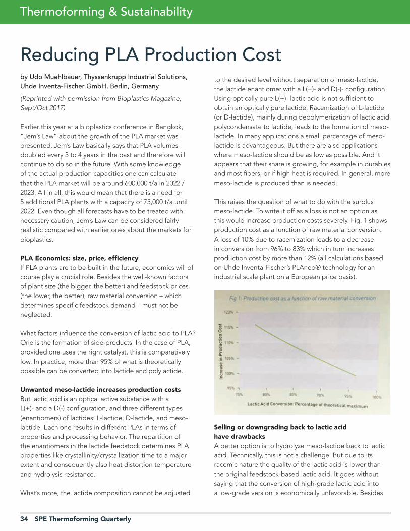
34 SPE Thermoforming Quarterly
Reducing PLA Production Cost
Thermoforming & Sustainability
by Udo Muehlbauer, Thyssenkrupp Industrial Solutions, Uhde Inventa-Fischer GmbH, Berlin, Germany(Reprinted with permission from Bioplastics Magazine, Sept/Oct 2017)
Earlier this year at a bioplastics conference in Bangkok, “Jem’s Law” about the growth of the PLA market was presented. Jem’s Law basically says that PLA volumes doubled every 3 to 4 years in the past and therefore will continue to do so in the future. With some knowledge of the actual production capacities one can calculate that the PLA market will be around 600,000 t/a in 2022 / 2023. All in all, this would mean that there is a need for 5 additional PLA plants with a capacity of 75,000 t/a until 2022. Even though all forecasts have to be treated with necessary caution, Jem’s Law can be considered fairly realistic compared with earlier ones about the markets for bioplastics.
PLA Economics: size, price, efficiencyIf PLA plants are to be built in the future, economics will of course play a crucial role. Besides the well-known factors of plant size (the bigger, the better) and feedstock prices (the lower, the better), raw material conversion – which determines specific feedstock demand – must not be neglected.
What factors influence the conversion of lactic acid to PLA? One is the formation of side-products. In the case of PLA, provided one uses the right catalyst, this is comparatively low. In practice, more than 95% of what is theoretically possible can be converted into lactide and polylactide.
Unwanted meso-lactide increases production costsBut lactic acid is an optical active substance with a L(+)- and a D(-) configuration, and three different types (enantiomers) of lactides: L-lactide, D-lactide, and meso-lactide. Each one results in different PLAs in terms of properties and processing behavior. The repartition of the enantiomers in the lactide feedstock determines PLA properties like crystallinity/crystallization time to a major extent and consequently also heat distortion temperature and hydrolysis resistance.
What’s more, the lactide composition cannot be adjusted
to the desired level without separation of meso-lactide, the lactide enantiomer with a L(+)- and D(-)- configuration. Using optically pure L(+)- lactic acid is not sufficient to obtain an optically pure lactide. Racemization of L-lactide (or D-lactide), mainly during depolymerization of lactic acid polycondensate to lactide, leads to the formation of meso-lactide. In many applications a small percentage of meso-lactide is advantageous. But there are also applications where meso-lactide should be as low as possible. And it appears that their share is growing, for example in durables and most fibers, or if high heat is required. In general, more meso-lactide is produced than is needed.
This raises the question of what to do with the surplus meso-lactide. To write it off as a loss is not an option as this would increase production costs severely. Fig. 1 shows production cost as a function of raw material conversion. A loss of 10% due to racemization leads to a decrease in conversion from 96% to 83% which in turn increases production cost by more than 12% (all calculations based on Uhde Inventa-Fischer’s PLAneo® technology for an industrial scale plant on a European price basis).
Selling or downgrading back to lactic acid have drawbacksA better option is to hydrolyze meso-lactide back to lactic acid. Technically, this is not a challenge. But due to its racemic nature the quality of the lactic acid is lower than the original feedstock-based lactic acid. It goes without saying that the conversion of high-grade lactic acid into a low-grade version is economically unfavorable. Besides
SPE Thermoforming Quarterly 35
bad economics, a producer of PLA has the drawback of having to deal with two completely different markets – selling PLA on the one hand and lactic acid to the cosmetics industry, for examples, on the other (unless he is already a lactic acid producer).
An even better option would be to sell meso-lactide as a chemical intermediate or monomer for different applications and to different markets with the aim of achieving higher prices. As meso-lactide has not existed as a commercial product before, there is no established market. New applications have to be developed and markets have to be found. Whether these markets will develop and to what size remains to be seen.
Using polymerized meso-lactide to form a single product: PLaneoThe solution that Uhde Inventa-Fischer has developed initially appears obvious: like L-lactide, meso-lactide is purified and polymerized. This is easier said than done, however. Beside the fact that meso-lactide is much more sensitive to side-reactions than usual polymer-grade lactide, the molecular weight of poly-meso-lactide has to be comparatively high in order to obtain good mechanical properties. Both facts add up to stringent requirements for the purity of polymer-grade meso-lactide.
The second step of the PLAneo technology is not as obvious. Instead of producing a second polymer, which would have limited possible applications due to its amorphous nature, polymeso-lactide is blended with the main crystallizable PLA-melt, both polymerized continuously in parallel lines, to give one product.
Optimized yield, same product propertiesThe resulting polymer maintains all relevant mechanical, optical and physical properties: tensile strength, E-modulus, crystallization behavior and melting point do not change. Only the b*-value of the PLA pellets is slightly increased. This holds true irrespective of whether distillation or crystallization is used to purify the main lactide stream. Processing of PLAneo is just as straightforward as standard PLA.
Applying separate polymerization of meso-lactide and L-lactide and blending it afterwards means no meso-lactide has to be discarded or used in a less economical way. The specific demand of lactic acid converges to its theoretical minimum of 1.25kg per kg of PLA.
Nobody knows exactly how the PLA market will develop. We will see whether Jem’s Law will continue to prove true in the future and how many new plants will come on-stream. But the ones using technology that maximizes raw material yield will definitely have an advantage. |
36 SPE Thermoforming Quarterly
SPE Council Summary
Council Meeting in Detroit
The following is a summary of the SPE Council Meeting held on August 25, 2017, in Detroit, Michigan. The official meeting minutes are posted to The Chain and contain complete details of attendees, policy and by-law changes, and procedural votes. Questions or comments? Contact Conor Carlin, VP Marketing & Communications at [email protected] or communicate via Leadership Lane on The Chain.
• SPE Financial Updateo CEO Pat Farrey provided details on SPE’s current financial position and offered his perspective from the world of association management. SPE members and leaders should not underappreciate our successes: Farrey pointed out that many associations would love to have our ANTEC numbers of 1400 attendees and $200k in revenue.o SPE has a strong cash position, the strongest for many years. Operational expenses are tracking on-budget. Corporate sales and membership dues are down leading to revenues that will be below budget by $377k, excluding the 1-time payment from Wiley for the journal publishing contract. Expenses are greater than revenues by $123k. Investment income of $220k helps to offset revenue losses though it cannot be relied upon for guaranteed future income.o Preliminary results show that ANTEC was profitable again in 2017. Costs were higher than budget and proportionally higher than historical numbers but in-line with expectations.o Membership dues have fallen to $70k/mo for the past two months, though overall membership totals are up, primarily driven by e-members.o It will be difficult to achieve corporate sales goals in 2017. Corporate sales are up 30% over 2016.
• CEO reportCEO Farrey offered that his observations at 60 days revealed no major surprises. His single strategic objective is to improve profitability. Short term priorities include the following:
o In-depth review of IT infrastructure and systems (ref. section 4.4 of 3YOP)
James Waddell
o More staff support for membership / affiliate group services through the hire of a new Member Services Managero Need to replace Business Development position. Need better focus on increasing non-dues revenue including advertising, corporate sponsorships and exhibit sales. (This position was filled as of September 2017).
Farrey also covered some additional topics:o Operational changes: re-integration of Managing Director role into CEO roleo Expense control: CEO review of all items including travel and capexo Longer term priorities: NGAB, young professionals, marcomms, awards
• recognition & awardso The structure of the Pinnacle Awards and related criteria have been reviewed by a sub-committee of the executive board. Vice-President of Education & Technology, Brian Landes, presented his group’s findings to Council. Complete details of the changes are available for members to access via The Chain where all presentations are posted. After discussion, Council decided to postpone implementation of the changes until after ANTEC 2018.o The Awards Committee called for reflection on nominees for the prestigious International Award. Other awards include the Research Award (contributions to polymer science), the Engineering Technology Award, the Business Award and the Education Award. All forms can be found online at www.4spe.org and the deadline is September 18.o President Al-Zubi recognized SPE Managing Director Russell Broome’s service to SPE and presented him with a plaque (plastic, not metal). Broome thanked everyone and encourage all members to focus on the needs of industry for SPE to remain vibrant and relevant.o President-Elect Brian Grady announced a new opening on the Nominating Committee. Councilor Scott Steele
SPE Thermoforming Quarterly 37
encourage everyone to find new candidates in order to have competitive elections.
• aNTECo The subject of commercial papers at ANTEC has been discussed for several years. Changes will now allow for technical marketing presentations. Templates have been created by Mark Spalding of Dow Chemical. Guidelines have been published and are available to membership. The goal is to allow more commercial information. While no official paper is required, a PowerPoint presentation will be reviewed by the ANTEC Program Committee. The presentations will subsequently be published alongside papers in the proceedings. Company logos are permitted but cannot consume more than 5% of the space on a slide.o Assigning of copyright to SPE for ANTEC papers will no longer be required. Instead the author will be required to grant SPE permission to publish, without surrendering copyright.o The ANTEC Task Force continues its important work on what changes are required to keep our flagship conference relevant and dynamic. VP Jaime Gomez cautioned that councilors should not extrapolate too much from early findings. Another update will be provided by December 2017.
• Sections & Divisions Newso The VP of Divisions, Creig Bowland, resigned his position due to work and family commitments. Since then, Jason Lyons of Arkema, has been appointed.o The Sections Committee has recently published a letter outlining their strategic projects to improve communication and member benefits. Members are encouraged to use The Chain for the latest news and information about affiliate groups and general SPE business.
• NGaB & PlastiVano Eve Vitale, Director of SPE Foundation, presented an overview of both the Foundation Board and PlastiVan (PV) programs. Currently, there are 4 educators and a program coordinator who are part of the PV team. Vitale reviewed scholarship programs and encouraged everyone to consider more ways to support plastics education via the PV program. All councilors had the opportunity make slime as Vitale led a demonstration of actual PV classroom education.o The Next Generation Advisory Board continues to grow. The current NGAB membership stands at 67. VP Gomez pointed out that 89% of student members do not renew their membership when they graduate and NGAB can act as a bridge to transition members from student status to young professional status. The Executive Board continues to commit essential resources for NGAB success. Councilor Jon Ratzlaff challenged councilors to bring this NGAB news to their respective boards and encouraged them to engage NGAB.
The next Council meeting will be on December 15th at 10am EST and will be conducted via conference call. |
Follow SPE Thermoforming Division on Twitter!
@SPEThermorEDUCE rEUSE rECyCLE
38 SPE Thermoforming Quarterly
n Advanced Extruder Technologies ................................ 29
n Assured Automation ...................................................... 16
n Brown Machinery ........................................................... 11
n CMT Materials ................................................................ 38
n Formed Plastics .............................................................. 16
n GN Thermoforming Equipment ................................... 17
n Illig .................................................................................... 5
n Irwin Research & Development .................................... 19
n MAAC Machinery ........................................................... 37
n O.M.G. SRL ..................................................................... 25
n Portage Casting & Mold ............................................... 16
n Premier Material Concepts ............................ Back Cover
n Profile Plastics. ............................................................... 38
n PTi Extruders ....................................... Inside Front Cover
n Sekisui Polymer Innovations, LLC. ................................ 13
n Senoplast ........................................................................ 38
n Siemens ................................................ Inside Back Cover
n Solar Products ................................................................ 35
n Thermoformer Parts Suppliers ...................................... 35
n TSL .................................................................................. 21
These sponsors enable us to publish SPE Thermoforming Quarterly
Sponsor Index
high quality plastic sheets and fi lms for thermoforming
www.senoplast.com
a member of klepsch group
Your local contact in USA:
Senoplast USA, Inc. · 75 Executive Drive, Suite 129 · Aurora · IL 60504 · USAT +1 630 898 0731 · offi [email protected] · www.senoplast.com
NAFTA HeadquartersParque Industrial Querétaro · Av. La Noria 123 · 76220 Santa Rosa Jáuregui · Qro. · MexicoT +52 422 19 4600 · offi [email protected] · www.senoplast.com
sen_az_en_93x102_rz.indd 1 28.02.2017 09:25:28

SPE Thermoforming Quarterly 39
siemens.com/siplus-hcs
Precise, space-saving, and efficient heat control increasesreliability and efficiency.SIPLUS Heating Control System (HCS)
Key benefi ts:
• Seamless integration into the automation architecture• Integrated diagnostic functions• UL certifi ed controllers • Space savings of up to 85% in the control cabinet
• Reductions of up to 80% in cabling work• Signifi cant cost savings• Energy effi ciency
©2
01
6 S
iem
ens
Ind
ust
ry,
Inc.

40 SPE Thermoforming Quarterly
REALIZE THE PMC DIFFERENCEPREMIER MATERIAL CONCEPTS877.289.7626 // [email protected] // buypmc.com
SHEET EXTRUSION& LAMINATIONOUR TEAM of extrusion professionals and materials experts will
help you find the right material for your demanding application.
ABS | TPO | ACRYLIC | ASA | PC/ABS SOFT-TOUCH | DECORATIVE FILMS & MORE!
COLLABORATION
EXECUTION
SUPPORT