
A Joint Standard of AASHTO, ITE, and NEMA
793
A Joint Standard of AASHTO, ITE, and NEMA NTCIP 1202 v03A National Transportation Communications for ITS Protocol Object Definitions for Actuated Signal Controllers (ASC) Interface Published in May 2019 (including FYA errata) Published by American Association of State Highway and Transportation Officials (AASHTO) 444 North Capitol Street, N.W., Suite 249 Washington, D.C. 20001 Institute of Transportation Engineers (ITE) 1627 Eye Street, N.W., Suite 600 Washington, D.C. 20006 National Electrical Manufacturers Association (NEMA) 1300 North 17th Street, Suite 900 Rosslyn, Virginia 22209-3801
Transcript of A Joint Standard of AASHTO, ITE, and NEMA

A Joint Standard of AASHTO, ITE, and NEMA
NTCIP 1202 v03A
National Transportation Communications for ITS Protocol
Object Definitions for Actuated Signal Controllers (ASC) Interface
Published in May 2019 (including FYA errata)
Published by American Association of State Highway and Transportation Officials (AASHTO) 444 North Capitol Street, N.W., Suite 249 Washington, D.C. 20001 Institute of Transportation Engineers (ITE) 1627 Eye Street, N.W., Suite 600 Washington, D.C. 20006 National Electrical Manufacturers Association (NEMA) 1300 North 17th Street, Suite 900 Rosslyn, Virginia 22209-3801
NOTICES
Copyright Notice 2019 by the American Association of State Highway and Transportation Officials (AASHTO), the Institute of Transportation Engineers (ITE), and the National Electrical Manufacturers Association (NEMA). All intellectual property rights, including, but not limited to, the rights of reproduction, translation, and display are reserved under the laws of the United States of America, the Universal Copyright Convention, the Berne Convention, and the International and Pan American Copyright Conventions. Except as licensed or permitted, you may not copy these materials without prior written permission from AASHTO, ITE, or NEMA. Use of these materials does not give you any rights of ownership or claim of copyright in or to these materials. Visit www.ntcip.org for other copyright information, for instructions to request reprints of excerpts, and to request reproduction that is not granted below. PDF File License Agreement To the extent that these materials are distributed by AASHTO / ITE / NEMA in the form of an Adobe® Portable Document Format (PDF) electronic data file (the “PDF file”), AASHTO / ITE / NEMA authorizes each registered PDF file user to view, download, copy, or print the PDF file available from the authorized Web site, subject to the terms and conditions of this license agreement:
a) you may download one copy of each PDF file for personal, noncommercial, and intraorganizational use only;
b) ownership of the PDF file is not transferred to you; you are licensed to use the PDF file; c) you may make one more electronic copy of the PDF file, such as to a second hard drive or burn
to a CD; d) you agree not to copy, distribute, or transfer the PDF file from that media to any other electronic
media or device; e) you may print one paper copy of the PDF file; f) you may make one paper reproduction of the printed copy; g) any permitted copies of the PDF file must retain the copyright notice, and any other proprietary
notices contained in the file; h) the PDF file license does not include (1) resale of the PDF file or copies, (2) republishing the
content in compendiums or anthologies, (3) publishing excerpts in commercial publications or works for hire, (4) editing or modification of the PDF file except those portions as permitted, (5) posting on network servers or distribution by electronic mail or from electronic storage devices, and (6) translation to other languages or conversion to other electronic formats;
i) other use of the PDF file and printed copy requires express, prior written consent. Data Dictionary and MIB Distribution Permission To the extent that these materials are distributed by AASHTO / ITE / NEMA in the form of a Data Dictionary (“DD”) or Management Information Base (“MIB”), AASHTO / ITE / NEMA extend the following permission: You may make or distribute unlimited copies, including derivative works, of the DD or MIB, including copies for commercial distribution, provided that:
a) each copy you make or distribute includes the citation “Derived from NTCIP 0000 [insert the standard number]. Copyright by AASHTO / ITE / NEMA. Used by permission.”;

b) the copies or derivative works are not made part of the standard publications or works offered by other standard developing organizations or publishers or as works-for-hire not associated with commercial hardware or software products intended for field implementation;
c) use of the DD or MIB is restricted in that the SYNTAX fields may only be modified to define: 1) a more restrictive subrange; or 2) a subset of the standard enumerated values; or 3) a set of retired and defined enumerated values for systems supporting multiversion interoperability;
d) the description field may be modified but only to the extent that: 1) the more restrictive subrange is defined; and 2) only those bit values or enumerated values that are supported are listed. [from 8002 A2 v04]
These materials are delivered “AS IS” without any warranties as to their use or performance. AASHTO / ITE / NEMA and their suppliers do not warrant the performance or results you may obtain by using these materials. AASHTO / ITE / NEMA and their suppliers make no warranties, express or implied, as to noninfringement of third party rights, merchantability, or fitness for any particular purpose. In no event will AASHTO / ITE / NEMA or their suppliers be liable to you or any third party for any claim or for any consequential, incidental or special damages, including any lost profits or lost savings, arising from your reproduction or use of these materials, even if an AASHTO / ITE / NEMA representative has been advised of the possibility of such damages. Some states or jurisdictions do not allow the exclusion or limitation of incidental, consequential, or special damages, or the exclusion of implied warranties, so the above limitations may not apply to a given user. Use of these materials does not constitute an endorsement or affiliation by or between AASHTO, ITE, or NEMA and the user, the user’s company, or the products and services of the user’s company. If the user is unwilling to accept the foregoing restrictions, he or she should immediately return these materials. PRL and RTM Distribution Permission To the extent that these materials are distributed by AASHTO / ITE / NEMA in the form of a Protocol Requirements List (“PRL”) or a Requirements Traceability Matrix (“RTM”), AASHTO / ITE / NEMA extend the following permission:
a) you may make or distribute unlimited copies, including derivative works of the PRL (then known as a Profile Implementation Conformance Statement (“PICS”)) or the RTM, provided that each copy you make or distribute contains the citation “Based on NTCIP 0000 [insert the standard number] PRL or RTM. Used by permission. Original text © AASHTO / ITE / NEMA.”;
b) you may only modify the PRL or the RTM by adding: 1) text in the Project Requirements column, which is the only column that may be modified to show a product’s implementation or the project-specific requirements; and/or 2) additional table columns or table rows that are clearly labeled as ADDITIONAL for project-unique or vendor-unique features; and
c) if the PRL or RTM excerpt is made from an unapproved draft, add to the citation “PRL (or RTM) excerpted from a draft standard containing preliminary information that is subject to change.”
This limited permission does not include reuse in works offered by other standards developing organizations or publishers, and does not include reuse in works-for-hire, compendiums, or electronic storage devices that are not associated with procurement documents, or commercial hardware, or commercial software products intended for field installation. A PRL is completed to indicate the features that are supported in an implementation. Visit www.ntcip.org for information on electronic copies of the MIBs, PRLs, and RTMs.
TRF Distribution Permission A Testing Requirements Form (“TRF”) may be a Testing Requirements Traceability Table and/or Test Procedures. To the extent that these materials are distributed by AASHTO / ITE / NEMA in the form of a TRF, AASHTO / ITE / NEMA extend the following permission:
a) you may make and/or distribute unlimited electronic or hard copies, including derivative works of the TRF, provided that each copy you make and/or distribute contains the citation “Based on NTCIP 0000 [insert the standard number] TRF. Used by permission. Original text © AASHTO / ITE / NEMA.”;
b) you may not modify the logical flow of any test procedure, without clearly noting and marking any such modification; and
c) if the TRF excerpt is made from an unapproved draft, add to the citation “TRF excerpted from a draft standard containing preliminary information that is subject to change.”
Content and Liability Disclaimer The information in this publication was considered technically sound by the consensus of persons engaged in the development and approval of the document at the time it was developed. Consensus does not necessarily mean that there is unanimous agreement among every person participating in the development of this document. AASHTO, ITE, and NEMA standards and guideline publications, of which the document contained herein is one, are developed through a voluntary consensus standards development process. This process brings together volunteers and seeks out the views of persons who have an interest in the topic covered by this publication. While AASHTO, ITE, and NEMA administer the process and establish rules to promote fairness in the development of consensus, they do not write the document and they do not independently test, evaluate, or verify the accuracy or completeness of any information or the soundness of any judgments contained in their standards and guideline publications. AASHTO, ITE, and NEMA disclaim liability for any personal injury, property, or other damages of any nature whatsoever, whether special, indirect, consequential, or compensatory, directly or indirectly resulting from the publication, use of, application, or reliance on this document. AASHTO, ITE, and NEMA disclaim and make no guaranty or warranty, express or implied, as to the accuracy or completeness of any information published herein, and disclaims and makes no warranty that the information in this document will fulfill any of your particular purposes or needs. AASHTO, ITE, and NEMA do not undertake to guarantee the performance of any individual manufacturer or seller’s products or services by virtue of this standard or guide. In publishing and making this document available, AASHTO, ITE, and NEMA are not undertaking to render professional or other services for or on behalf of any person or entity, nor are AASHTO, ITE, and NEMA undertaking to perform any duty owed by any person or entity to someone else. Anyone using this document should rely on his or her own independent judgment or, as appropriate, seek the advice of a competent professional in determining the exercise of reasonable care in any given circumstances. Information and other standards on the topic covered by this publication may be available from other sources, which the user may wish to consult for additional views or information not covered by this publication. AASHTO, ITE, and NEMA have no power, nor do they undertake to police or enforce compliance with the contents of this document. AASHTO, ITE, and NEMA do not certify, test, or inspect products, designs, or installations for safety or health purposes. Any certification or other statement of compliance with any health or safety-related information in this document shall not be attributable to AASHTO, ITE, or NEMA and is solely the responsibility of the certifier or maker of the statement.

NTCIP 1202 v03A.28 Page i
© 2019 AASHTO / ITE / NEMA Do Not Copy Without Written Permission
Acknowledgements
NTCIP 1202 v03 was prepared by the NTCIP Actuated Signal Controller Working Group (ASC WG), which is a subdivision of the Joint Committee on the NTCIP. The NTCIP Joint Committee is organized under a Memorandum of Understanding among the American Association of State Highway and Transportation Officials (AASHTO), the Institute of Transportation Engineers (ITE), and the National Electrical Manufacturers Association (NEMA). The NTCIP Joint Committee consists of six representatives from each of the standards organizations, and provides guidance for NTCIP development. When NTCIP 1202 v03 was prepared, the following individuals were voting (indicated by an asterisk) or alternate voting members of the NTCIP ASC WG:
• City of Anaheim, John Thai* (Co-Chair) • Consensus Systems Technologies,
Patrick Chan*, Manny Insignares • Eberle Design, Inc., *Scott Evans* • Econolite Control Products, Inc., Gary
Duncan, Greg Mizell*, Dustin DeVoe • Florida DOT, Matthew DeWitt*, Jeffrey
Morgan, Derek Vollmer • Intelight, Doug Tarico* (Co-Chair), Peter
Ragsdale, Doug Crawford, Craig Gardner, Grant Gardner
• Peek Traffic Corporation, Mark Simpson*, Ray Deer
• Pillar Consulting, Ralph Boaz* • Texas A&M University (TTI), Kevin
Balke*, Hassan Charara, Srinivasa Sunkari
• TransCore, ITS, David Benevelli, Keith Patton, Robert Rausch*
Observing members include:
• Applied Information, Inc. , Bryan Mulligan, Alan Clelland
• Kapsch, Joerg “Nu” Rosenbohm • Kimley-Horn, Bob Barkley • KLD, Wuping Xin • McCain Inc., Donald Maas Jr., • North Carolina DOT, Greg Fuller
• Southwest Research Institute, Cameron Mott
• The University of Arizona, Larry Head • Trafficware Engineered by Naztec,
Clyde Neel • Trevilon Corp., Kenneth Vaughn • WSP, Christopher Toth, Thomas
Timcho, Erica Toussant, Nora Wisor Additional stakeholders who provided input or monitored development include:
• Arcadis U.S., Inc., David Ritchie • Battelle, Jeffrey Arch, Greg Zink • CA DOT (CalTrans), Herasmo Iniguez,
Brian Simi, Ted Lombardi, Antonio Sarmiento, Stan Slavin
• Diablo Controls, Inc., Allen Jacobs • Global Traffic Technologies, LLC,
Christian Kulus • Gridaptive, Jim Frazer • SCSC, David Kelley • Jacobs, Diederick VanDillen • Mid-America Regional Council, Ray
Webb • Miovision, Jan Bergstrom, Dave Hillis • Mixon Hill, Lee Mixon
• Minnesota DOT, Peter Skweres, Ray Starr
• New Jersey DOT, Jeevanjot Singh • New York City DOT, Rami Khashashina,
Mohammad Talas • Oregon DOT, K. Groves, Roger
Boettcher • Overland Park, KS, Shawn Gotfredson • Oz Engineering, Tom Guerra • Parsons, Jon Wyatt • PR Olson Associates, Paul Olson • Reno A&E, Matt Zinn • SAE International, Keith Wilson • Sandag, Peter Thompson

NTCIP 1202 v03A.28 Page ii
Do Not Copy Without Written Permission © 2019 AASHTO / ITE / NEMA
• Siemens Industry, Inc., Glenn Massarano, Dave Miller, Daniel Nelson,
Andrew Valdez • Utah DOT, Shane Johnson
In addition to the many volunteer efforts, recognition is also given to those organizations that supported the effort by providing funding:
• U.S. Department of Transportation

NTCIP 1202 v03A.28 Page iii
© 2019 AASHTO / ITE / NEMA Do Not Copy Without Written Permission
Foreword
NTCIP 1202 v03, an NTCIP standards publication, identifies and defines how a management station may wish to interface with a field device to control and monitor traffic signal controllers and associated detectors in an NTCIP-conformant fashion. NTCIP 1202 v03 uses only metric units. NTCIP 1202 v03 is titled Actuated Signal Controllers (ASC) Interface Protocol to express the multiple sections and annexes that are included in NTCIP 1202 v03. This NTCIP 1200-series standards publication has grown beyond the “object definitions” that were reflected in the title for its predecessors, NTCIP 1202 versions v01 and v02 (2005). NTCIP 1202 v03 defines data elements for use with Actuated Signal Controller Units. The data is defined using the Simple Network Management Protocol (SNMP) object-type format as defined in RFC 1212 and the defined NTCIP format defined in NTCIP 8004. This data would typically be exchanged using one of the NTCIP 1103 recognized Application Layers (e.g., SNMP). NTCIP 1202 v03 follows an established systems engineering approach to support procurement processes. The PRL is designed to allow an agency to indicate what user needs are applicable to a procurement, and to select which requirements are to be implemented in a project specific implementation. Proper completion of the PRL by the agency results in a specification that is more likely to satisfy the agency’s project needs and that is conformant to NTCIP 1202 v03. The RTM defines the interface specifications for those requirements selected, and can be used to develop the test plans and test procedures. The following keywords apply to this document: AASHTO, ITE, NEMA, NTCIP, ASC, data, data dictionary, object, MIB, PRL and RTM. NTCIP 1202 v03 includes a number of normative and four informative annexes. NTCIP 1202 v03 is also an NTCIP Data Dictionary standard. Data Dictionary standards provide definitions of data concepts (messages, data frames, and data elements) for use within NTCIP systems; and are approved by AASHTO, ITE, and NEMA through a ballot process, after a recommendation by the NTCIP Joint Committee. For more information about NTCIP standards, or to acquire the related NTCIP 1202 v03 MIB, visit www.ntcip.org. NTCIP 1202 v03A Errata (associated with Flashing Yellow Arrow (FYA)) As NTCIP 1202 v03 was about to be published and distributed, a user provided proposed clarifications/corrections associated with experience in implementing the Flashing Yellow Arrow (FYA) functionality described in Sections 5.9.2.7, 7.2.5.3, 7.2.5.11, and 7.2.7.1. The clarifications/corrections associated with these sections are shown using track changes (in the copy of these sections that follows), and later in NTCIP 1202 v03A (without track changes). These clarifications/corrections constitute the FYA errata 5.9.2.7 Channel Included Movements channelGreenIncluded OBJECT-TYPE
SYNTAX OCTET STRING ACCESS read-write STATUS mandatory DESCRIPTION "<Definition> If the channelGreenType for this channel is
'protected (2)', this object is used to indicate if and when this movement is in permissive mode. This object is used to support the generation of SPAT data and defines the signalState (See signalState) for the movements associated with this channel only IF the channelGreenType for this channel is 'protected (2)'. Each

NTCIP 1202 v03A.28 Page iv
Do Not Copy Without Written Permission © 2019 AASHTO / ITE / NEMA
octet in the octet string represents a conflicting or opposing channelNumber, which if the status for any octet in the octet string is NOT Channel Red or is Dark, then the signalState for the movementis channelNumber is 'permissive-Movement-Allowed (5)' when the status for this channel is channel Green. Otherwise, the signalState for the movement is channelNumber is 'protected-Movement-Allowed (6)' when the status for this channel is channel Green.
If channelGreenType in this row is not 'protected (2)', then this
object value is ignored. It is assumed that a clearance state following a signalState of 'permissive movement allowed' will be a signalState of 'permissive clearance', and a clearance state following a signalState of 'protected movement allowed' will be follow a signalState of 'permissive 'protected movement allowed'. and a signalState of 'protected clearance' follows 'protected movement allowed'. For example, assume channelNumber 1 represents a northbound left turn, while channelNumber 2 is a southbound through movement. A channelGreenType.1 of 'protected (2)' and channelGreenIncluded.1 of '02' indicates that if the status of channelNumber 2 is NOT Channel Red or is dark, then signalState for the movement associated with channelNumber.1 is 'permissive-Movement-Allowed (5)' when the status for channelNumber.1 is channel Green. Otherwise, the signalState for the movement associated with channelNumber.1 is 'protected-Movement-Allowed (6)' when the status for this channel is channel Green.
<Object Identifier> 1.3.6.1.4.1.1206.4.2.1.8.2.1.7" ::= { channelEntry 7 } 7.2.5.3 SPaT Movement Maneuver State movementManeuverState OBJECT-TYPE
SYNTAX INTEGER (0..9) ACCESS read-only STATUS mandatory DESCRIPTION "<Definition> For NTCIP 1202 user clarification, this
object defines the state of a specific movement maneuver (lane connection) at the intersection, unlike signalState, which defines the general state of a channel. This object value is determined as follows where Column A is the movementManeuverGreenType, Column B is the movementManeuverGreenIncluded, and Column C is the channel output for the channelNumber:
+-----------------+-----------------+-----+-----------------+--------+ | movementManeuver| | | | | | State | A | B | C | Notes | +-----------------+-----------------+-----+-----------------+--------+ | unavailable (0) | Any | Any | Unavailable | | | 1 - See Note GFE | Any | Any | See Note A |
| | 2 - See Note GFE | flashRed (5) | 0 | Green or Red |
| | 3 - See Note G | Any | Any | Red | Note B |

NTCIP 1202 v03A.28 Page v
© 2019 AASHTO / ITE / NEMA Do Not Copy Without Written Permission
| 4 - See Note GFE | N/A | N/A | N/A | |
| 5 - See Note GFE | permissive (3) | 0 | Green | |
| 5 - See Note GF | protected (2) | > 0 | Green Not Yellow or Red| Note CB |
| 6 - See Note GFE | protected (2) | > 0 | Green Not Yellow or Red| Note DCB |
| 6 - See Note GFE | protected (2) | 0 | Green | |
| 7 - See Note GFE | Any | Any | Yellow | Note ED |
| 8 - See Note GFE | protected (2) | Any | Yellow | Note FE |
| 9 - See Note GFE | flashYellow (4) | 0 | Green or Yellow | |
+-----------------+-----------------+-----+-----------------+--------+ Note A: The channel output is neither Not Green, Yellow or Red. Note B: If this movement maneuver is controlled by a 4-section head or
5-section head, and the signal indication is 'Red', then this movement maneuver is also considered 'Red'.
Note CB: If one or more of the octets in movementManeuverGreenIncluded
is NOT 'Red' or is Dark. Note DC: If all octets in movementManeuverGreenIncluded are 'Red' or
Dark. Note EDC: Only ifUnless the preceding movementManeuverState was
protectedpermissive-movement-allowed. Note FED: Only if the preceding movementManeuverState was protected-
movement-allowed. Note GFE: The definition of the value can be found in SAE J2735_201603
DE_MovementPhaseState. For example, the object value is '6' if the movementManeuverGreenType
is protected (2), and allny of the octets in movementManeuverGreenIncluded (each representing a channelNumber) areis NOT 'Red' or is Dark; OR if the movementManeuverGreenType is protected (2) and the movementManeuverGreenIncluded is 00.
If the movementManeuverTable is used, this object may be exchanged between the ASC and the CV Roadside Process in lieu of the signalState object.
<Object Identifier> 1.3.6.1.4.1.1206.4.2.17.1.5.1.3" REFERENCE "SAE J2735_201603 DE_MovementPhaseState"
::= { movementManeuverEntry 3 } 7.2.5.11 SPaT Movement Included Movements movementManeuverGreenIncluded OBJECT-TYPE
SYNTAX OCTET STRING ACCESS read-write STATUS mandatory DESCRIPTION "<Definition> If the movementManeuverGreenType for this
movement maneuver is 'protected (2)', this object is used to indicate if and when this movement maneuver is in permissive mode. This object is used to support the generation of SPAT data and defines the movementManeuverState for this movement maneuver only IF the maneuverMovementGreenType is 'protected (2)'. Each

NTCIP 1202 v03A.28 Page vi
Do Not Copy Without Written Permission © 2019 AASHTO / ITE / NEMA
octet in the octet string represents a conflicting or opposing channelNumber, which if the status for any octet in the octet string is NOT Channel Red or is dark, then the movementManeuverState for this movement maneuver is 'permissive-Movement-Allowed (5)' when the status for this channel is channel Green. Otherwise, the movementManeuverState for this movement maneuver channelNumber is 'protected-Movement-Allowed (6)' when the status for this channel is channel Green.
If movementManeuverGreenType in this row is not 'protected (2)',
then this object value is ignored. It is assumed that a clearance state following a movementManeuverState of 'permissive movement allowed' will be a movementManeuverState of 'permissive clearance', and a clearance state will following a movementManeuverState of 'protected 'permissive movement allowed' will be and a movementManeuverState of 'protected clearance'. follows 'protected movement allowed'. For example, assume channelNumber 1 represents a northbound left turn, while channelNumber 2 is a southbound through movement. A channelGreenType.1 of 'protected (2)' and channelGreenIncluded.1 of '02' indicates that if the status of channelNumber 2 is NOT Channel Red or is dark, then the movementManeuverState for the movement associated with channelNumber.1 is 'permissive-Movement-Allowed (5)' when the status for channelNumber.1 is channel Green. Otherwise, the movementManeuverState for the movement associated with channelNumber.1 is 'protected-Movement-Allowed (6)' when the status for this channel is channel Green.
<Object Identifier> 1.3.6.1.4.1.1206.4.2.17.1.5.1.11" ::= { movementManeuverEntry 11 } 7.2.7.1 SPaT Event State signalState OBJECT-TYPE
SYNTAX INTEGER (0..9) ACCESS read-only STATUS mandatory DESCRIPTION "<Definition> For NTCIP 1202 user clarification, this
object value defines the movement state (e.g., permitted, protected) of a channel. This object is determined as follows where Column A is the channelGreenType, Column B is the channelGreenIncluded, and Column C is the channel output for the channelNumber:
+-----------------+-----------------+-----+-----------------+--------+ | signalState | A | B | C | Notes | +-----------------+-----------------+-----+-----------------+--------+ | unavailable (0) | Any | Any | Unavailable | | | 1 - See Note GFE | Any | Any | See Note A |
| | 2 - See Note GFE | flashRed (5) | 0 | Green or Red | Note B
| | 3 - See Note GFE | Any | Any | Red |
| | 4 - See Note GFE | N/A | N/A | N/A |
| | 5 - See Note GFE | permissive (3) | 0 | Green |
|

NTCIP 1202 v03A.28 Page vii
© 2019 AASHTO / ITE / NEMA Do Not Copy Without Written Permission
| 5 - See Note GF | protected (2) | > 0 | Green | Note CB |
| 6 - See Note GFE | protected (2) | > 0 | Green | Note DCB |
| 6 - See Note GFE | protected (2) | 0 | Green | |
| 7 - See Note GFE | Any | Any | Yellow | Note ED |
| 8 - See Note GFE | protected (2) | Any | Yellow | Note FE |
| 9 - See Note GFE | flashYellow (4) | 0 | Green or Yellow | |
+-----------------+-----------------+-----+-----------------+--------+ Note A: The channel output is neither Not Green, Yellow or Red. Note B: If this movement state is controlled by a 4-section head or 5-
section head, and the signal indication is 'Red', then this movement maneuver is also considered 'Red'.
Note CB: If one or more of the octets in channelGreenIncluded is NotOTnot 'Red' or is dark.
Note DC: If all octets in channelGreenIncluded are 'Red' or Dark. Note EDC: Only ifUnless the preceding signalState was
protectedpermissive-movement-allowed. Note FED: Only if the preceding signalState was protected-movement-
allowed. Note GFE: The definition of the value can be found in SAE J2735_201603
DE_MovementPhaseState. For example, the object value is '6' if the channelGreenType is
protected (2), and allany of the octets in channelGreenIncluded (each representing a channelNumber) areis NOT 'Red' or is Dark; OR if the channelGreenType is protected (2) and the channelGreenIncluded is 00.
Note this object provides the movement state of the channel in general,
unlike movementManeuverState which defines the movement state of a specific movement maneuver (from what lane to what lane). This object may be exchanged between the ASC and CV Roadside Process if the movementManeuverState is not used.
<Object Identifier> 1.3.6.1.4.1.1206.4.2.17.1.7.1.1" REFERENCE "SAE J2735_201603 DE_MovementPhaseState"
::= { signalStatusEntry 1 } In addition, Sections 5.0 and 7.1 were revised to ‘rev’ the document name of associated MIBs, and their date of publication. User Comment Instructions The term “User Comment” includes any type of written inquiry, comment, question, or proposed revision, from an individual person or organization, about any NTCIP 1202 v03 content. A “Request for Interpretation” is also classified as a User Comment. User Comments are solicited at any time. In preparation of this NTCIP standards publication, input of users and other interested parties was sought and evaluated.

NTCIP 1202 v03A.28 Page viii
Do Not Copy Without Written Permission © 2019 AASHTO / ITE / NEMA
User Comments are generally referred to the committee responsible for developing and/or maintaining NTCIP 1202 v03. The committee chairperson, or their designee, may contact the submitter for clarification of the User Comment. When the committee chairperson or designee reports the committee’s consensus opinion related to the User Comment, that opinion is forwarded to the submitter. The committee chairperson may report that action on the User Comment may be deferred to a future committee meeting and/or a future revision of the standards publication. Previous User Comments and their disposition may be available for reference and information at www.ntcip.org. A User Comment should be submitted to this address:
NTCIP Coordinator National Electrical Manufacturers Association 1300 North 17th Street, Suite 900 Rosslyn, Virginia 22209-3801 e-mail: [email protected]
A User Comment should be submitted in the following form:
Standard Publication number and version: Page: Section, Paragraph, or Clause: Comment: Editorial or Substantive?: Suggested Alternative Language:
Please include your name, organization, and address in your correspondence. Approvals NTCIP 1202 v03 was separately balloted and approved by AASHTO, ITE, and NEMA after recommendation by the Joint Committee on the NTCIP. Each organization has approved NTCIP 1202 v03 as the following standard type, as of the date:
AASHTO—Standard Specification; December, 2018 ITE—Software Standard; January, 2019 NEMA—Standard; December, 2018
History In 1992, the NEMA 3TS Transportation Management Systems and Associated Control Devices Section began the effort to develop NTCIP. Under the guidance of the Federal Highway Administration’s NTCIP Steering Group, the NEMA effort was expanded to include the development of communications standards for all transportation field devices that could be used in an ITS network. In September 1996, an agreement was executed among AASHTO, ITE, and NEMA to jointly develop, approve, and maintain the NTCIP standards. In late 1998, the Actuated Signal Controller Working Group was tasked with the effort to update the Actuated Traffic Signal Controller Object Definitions document. The first meeting of this working group was held in October 1999. From 1996 to 1999, this document was referenced as NEMA TS 3.5-1996. However, to provide an organized numbering scheme for the NTCIP documents, this document is now referenced as NTCIP 1202. As included in the following development history, NTCIP 1202 has experienced revisions over time:
NEMA TS 3.5-1996. 1996 – Approved by NEMA. 1996 – Accepted as a Recommended Standard by the Joint Committee on the NTCIP. 1997 – Approved by AASHTO and ITE.

NTCIP 1202 v03A.28 Page ix
© 2019 AASHTO / ITE / NEMA Do Not Copy Without Written Permission
v01.07a printed with NEMA cover. NTCIP 1202 v01. v01.07b printed with joint cover. v01.07c printed to PDF in November 2002. v01.07d printed to PDF for no-cost distribution January 2005. NTCIP 1202 Amendment 1. November 1999 – Accepted as a User Comment Draft Amendment by the Joint Committee on the NTCIP. April 2000 – NTCIP Standards Bulletin B0049 sent NTCIP 1202 Amendment 1 v01.06b for user comment. NTCIP 1202 Amendment 1, a User Comment Draft, was incorporated into 1202v02, and was not advanced further. NTCIP 1202 v02.10. June 2001 – Accepted as a User Comment Draft by the Joint Committee on the NTCIP. February 2002 – NTCIP Standards Bulletin B0068 referred v02.13 for user review and comment. NTCIP 1202 v02.16. October 2002 – Accepted as a Recommended Standard by the Joint Committee on the NTCIP. April 2004 – NTCIP Standards Bulletin B0091 referred v02.18 for balloting. Approved by AASHTO in November 2004, approved by ITE in March 2005, and approved by NEMA in November 2004. NTCIP 1202:2005 v02.19. November 2005 – Edited document for publication. By the terms of MOU on CTPA article 1.2, the ownership of version 02 was assigned to AASHTO, ITE, and NEMA because the preexisting work was revised by more than 50%. NTCIP 1202 v03 was developed to reflect lessons learned, to update the document to the new documentation formats, and to add new features such as support for a connected vehicle interface. NTCIP 1202 v03 also follows an established systems engineering approach. Several new sections were added to relate user needs identified in a concept of operations, functional requirements, interface specifications and a requirements traceability matrix to the existing sections.
Compatibility of Versions To distinguish NTCIP 1202 v03A (as published) from previous drafts, NTCIP 1202 v03A also includes NTCIP 1202 v03A.28 on each page header. All NTCIP Standards Publications have a major and minor version number for configuration management. The version number SYNTAX is "v00.00a," with the major version number before the period, and the minor version number and edition letter (if any) after the period.
Note: NTCIP 1202 v03A differs from NTCIP 1202 v03 in that NTCIP 1202 v03A contains clarifications and corrections resulting from implementer experience associated with Flashing Yellow Arrow (FYA) functionality, and constitute the FYA errata.
The MIB associated with NTCIP 1202 v03A (as published) is 1202v0328.MIB. In addition, the 1217v0128.MIB is available through SAE. NTCIP 1202 v03A is designated, and should be cited as, NTCIP 1202 v03A. Anyone using NTCIP 1202 v03 should seek information about the version number that is of interest to them in any given circumstance. The PRL, RTM and the MIB should all reference the version number of the standards publication that was the source of the excerpted material.
Note: TPG users should enter Standard Number 1202, Major Version Number 03, Minor Version Number 28, and browse for the TPG-enabled version of NTCIP 1202 v03A.
Compliant systems based on later, or higher, version numbers MAY NOT be compatible with compliant systems based on earlier, or lower, version numbers. Anyone using NTCIP 1202 v03A should also consult NTCIP 8004 v02 for specific guidelines on compatibility.

NTCIP 1202 v03A.28 Page x
Do Not Copy Without Written Permission © 2019 AASHTO / ITE / NEMA
Note: NTCIP 1202 v03A retains references to NTCIP 1202 v03 in text (self-references).

NTCIP 1202 v03A.28 Page xi
© 2019 AASHTO / ITE / NEMA Do Not Copy Without Written Permission
CONTENTS
Note: The following Contents listing includes seven heading levels (for annexes) to permit TPG evaluation.
Page
Section 1 General [Informative] ................................................................................................................. 1 1.1 Scope .......................................................................................................................................... 1 1.2 References .................................................................................................................................. 2
1.2.1 Normative References ................................................................................................ 2 1.2.2 Other References ........................................................................................................ 3 1.2.3 Contact Information ..................................................................................................... 3
1.3 General Statements .................................................................................................................... 4 1.4 Terms .......................................................................................................................................... 4 1.5 Abbreviations ............................................................................................................................ 13
Section 2 Concept of Operations [Normative] ....................................................................................... 14 2.1 Tutorial [Informative] ................................................................................................................. 14 2.2 Current Situation and Problem Statement [Informative] ........................................................... 15 2.3 Reference Physical Architecture [Informative] .......................................................................... 16
2.3.1 ASC Characteristics – Cabinet Specifications .......................................................... 18 2.3.2 ASC Characteristics – Controller Types.................................................................... 20 2.3.3 ASC Characteristics – Connected Vehicle Interface ................................................. 20
2.4 Architectural Needs ................................................................................................................... 22 2.4.1 Provide Live Data ...................................................................................................... 23 2.4.2 Provide Dynamic Object Data ................................................................................... 23 2.4.3 Provide Block Data .................................................................................................... 23 2.4.4 Provide for Log Data Local Storage and Retrieval .................................................... 23 2.4.5 Provide for Database Management .......................................................................... 23 2.4.6 Condition-based Exception Reporting....................................................................... 24
2.5 Features .................................................................................................................................... 24 2.5.1 Manage the ASC Configuration ................................................................................ 24 2.5.2 Manage Signal Operations ........................................................................................ 25 2.5.3 Manage Detectors ..................................................................................................... 31 2.5.4 Manage Connected Vehicles Interface ..................................................................... 31 2.5.5 Backward Compatibility Features.............................................................................. 35
2.6 Security ..................................................................................................................................... 35 2.6.1 Manage Authentication ............................................................................................. 36 2.6.2 Manage Accessibility ................................................................................................. 36 2.6.3 Manage Users ........................................................................................................... 36 2.6.4 Log User Access ....................................................................................................... 36
2.7 Operational Policies and Constraints ........................................................................................ 36 2.8 Relationship to the ITS National Architecture [Informative] ...................................................... 36
Section 3 Functional Requirements [Normative] ................................................................................... 39 3.1 Tutorial [Informative] ................................................................................................................. 39 3.2 Scope Of The Interface [Informative] ........................................................................................ 40 3.3 Protocol Requirements List (PRL) ............................................................................................ 40
3.3.1 Notation [Informative] ................................................................................................ 40 3.3.2 Instructions for Completing the PRL [Informative] .................................................... 42 3.3.3 Protocol Requirements List (PRL) Table .................................................................. 43
NTCIP 1202 v03A.28 Page xii
Do Not Copy Without Written Permission © 2019 AASHTO / ITE / NEMA
3.4 Architectural Requirements ...................................................................................................... 98 3.4.1 Support Basic Communications Requirements ........................................................ 98 3.4.2 Support Logged Data Requirements ........................................................................ 98 3.4.3 Support Exception Reporting Requirements ............................................................. 98 3.4.4 Manage Access Requirements ................................................................................. 98
3.5 Data Exchange and Operational Environment Requirements .................................................. 99 3.5.1 ASC Configuration Management Requirements ....................................................... 99 3.5.2 Manage Signal Operations Management Requirements ........................................ 105 3.5.3 Detector Management Requirements ..................................................................... 166 3.5.4 Connected Vehicles Interface Management ........................................................... 177 3.5.5 Backward Compatibility Requirements ................................................................... 208
3.6 Supplemental Non-communications Requirements ............................................................... 208 3.6.1 Response Time for Requests .................................................................................. 209 3.6.2 Condition-based Maximum Transmission Start Time ............................................. 209 3.6.3 Signal Phase and Timing Data Performance Requirements .................................. 209
Section 4 Dialogs [Normative] ............................................................................................................... 211 4.1 Tutorial [Informative] ............................................................................................................... 212 4.2 Specified Dialogs .................................................................................................................... 213
4.2.1 Get Block Data ........................................................................................................ 213 4.2.2 Set Complex Configuration Parameters (called 'P2' Objects in NTCIP 1202 v02) . 213 4.2.3 Set Block Data ......................................................................................................... 216 4.2.4 Setup, Programming, and Processing of I/O Mapping............................................ 217 4.2.5 Making an I/O Map Active ....................................................................................... 218 4.2.6 Configure Speed Limits for a Node Point ................................................................ 218 4.2.7 Enable Collection of Connected Data ..................................................................... 218 4.2.8 Retrieve Connected Device Detector Zone - Geographic....................................... 219 4.2.9 Configure Enabled Lanes ........................................................................................ 219 4.2.10 Provide Detection Reports to an ASC ..................................................................... 220 4.2.11 Activating a MAP Plan ............................................................................................. 220 4.2.12 Confirm MAP Compatibility ..................................................................................... 220
4.3 State-Transition Diagrams ...................................................................................................... 221 4.3.1 Data Parameter Types ............................................................................................ 221 4.3.2 Consistency Checks ................................................................................................ 222 4.3.3 Non-Sequential Time Change ................................................................................. 227
Section 5 Management Information Base (MIB) [Normative] ............................................................. 228 5.0 MIB Comment Header ............................................................................................................ 228 5.1 MIB Header ............................................................................................................................. 228 5.2 Phase Parameters .................................................................................................................. 229
5.2.1 Maximum Phases .................................................................................................... 229 5.2.2 Phase Table ............................................................................................................ 229 5.2.3 Maximum Phase Groups ......................................................................................... 242 5.2.4 Phase Status Group Table ...................................................................................... 242 5.2.5 Phase Control Table ............................................................................................... 247
5.3 Detector Parameters ............................................................................................................... 251 5.3.1 Maximum Vehicle Detectors ................................................................................... 251 5.3.2 Vehicle Detector Parameter Table .......................................................................... 251 5.3.3 Maximum Vehicle Detector Status Groups ............................................................. 259 5.3.4 Vehicle Detector Status Group Table ..................................................................... 259 5.3.5 Volume / Occupancy Report ................................................................................... 261 5.3.6 Maximum Pedestrian Detectors .............................................................................. 265 5.3.7 Pedestrian Detector Parameter Table..................................................................... 265 5.3.8 Maximum Pedestrian Detector Groups ................................................................... 268
NTCIP 1202 v03A.28 Page xiii
© 2019 AASHTO / ITE / NEMA Do Not Copy Without Written Permission
5.3.9 Pedestrian Detector Status Group Table ................................................................ 269 5.3.10 Pedestrian Detector Report ..................................................................................... 270 5.3.11 Maximum Vehicle Detector Control Groups ............................................................ 274 5.3.12 Pedestrian Detector Control Group Table ............................................................... 275
5.4 Unit Parameters ...................................................................................................................... 276 5.4.1 Startup Flash Parameter ......................................................................................... 277 5.4.2 Automatic Ped Clear Parameter ............................................................................. 277 5.4.3 Backup Time Parameter ......................................................................................... 277 5.4.4 Unit Red Revert Parameter ..................................................................................... 278 5.4.5 Unit Control Status .................................................................................................. 278 5.4.6 Unit Flash Status ..................................................................................................... 279 5.4.7 Unit Alarm Status 2 ................................................................................................. 279 5.4.8 Unit Alarm Status 1 ................................................................................................. 280 5.4.9 Short Alarm Status .................................................................................................. 281 5.4.10 Unit Control ............................................................................................................. 281 5.4.11 Maximum Alarm Groups ......................................................................................... 282 5.4.12 Alarm Group Table .................................................................................................. 282 5.4.13 Maximum Special Function Outputs ....................................................................... 283 5.4.14 Special Function Output Table ................................................................................ 283 5.4.15 Remote Manual Control Timer ................................................................................ 285 5.4.16 Remote Manual Control Advance Command ......................................................... 285 5.4.17 ASC Elevation - Antenna Offset .............................................................................. 286 5.4.18 Startup Flash Mode ................................................................................................. 286 5.4.19 Backup Timer Parameter - User Defined ................................................................ 286 5.4.20 Maximum Number of User Definable OIDs for Backup Timer ................................ 287 5.4.21 Backup Time - User Defined Functions Table ........................................................ 287 5.4.22 ASC Clock ............................................................................................................... 288 5.4.23 Communications...................................................................................................... 293 5.4.24 Maximum Number of OIDs for Global Set ID Parameter ........................................ 301 5.4.25 Global Set ID Parameter Definition Table ............................................................... 301 5.4.26 Unit Alarm Status 3 ................................................................................................. 302 5.4.27 Unit Alarm Status 4 ................................................................................................. 303
5.5 Coordination Parameters ........................................................................................................ 303 5.5.1 Coord Operational Mode Parameter ....................................................................... 303 5.5.2 Coord Correction Mode Parameters ....................................................................... 304 5.5.3 Coord Maximum Mode Parameter .......................................................................... 304 5.5.4 Coord Force Mode Parameter ................................................................................ 305 5.5.5 Maximum Patterns Parameter ................................................................................ 305 5.5.6 Pattern Table Type .................................................................................................. 305 5.5.7 Pattern Table ........................................................................................................... 306 5.5.8 Maximum Splits ....................................................................................................... 309 5.5.9 Split Table ............................................................................................................... 310 5.5.10 Coordination Pattern Status .................................................................................... 313 5.5.11 Local Free Status .................................................................................................... 313 5.5.12 Coordination Cycle Status ....................................................................................... 314 5.5.13 Coordination Sync Status ........................................................................................ 314 5.5.14 System Pattern Control ........................................................................................... 314 5.5.15 System Sync Control ............................................................................................... 315 5.5.16 Unit Coordination Sync Point .................................................................................. 315
5.6 Time Base Parameters ........................................................................................................... 316 5.6.1 Time Base Pattern Sync Parameter ........................................................................ 316 5.6.2 Maximum Time Base Actions .................................................................................. 316 5.6.3 Time Base Asc Action Table ................................................................................... 316 5.6.4 Time Base Asc Action Status .................................................................................. 318 5.6.5 Action Plan Command ............................................................................................ 318
NTCIP 1202 v03A.28 Page xiv
Do Not Copy Without Written Permission © 2019 AASHTO / ITE / NEMA
5.7 Preempt Parameters ............................................................................................................... 319 5.7.1 Maximum Preempts ................................................................................................ 319 5.7.2 Preempt Table ......................................................................................................... 319 5.7.3 Preempt Control Table ............................................................................................ 329 5.7.4 Preempt Status ........................................................................................................ 330 5.7.5 Maximum Preempt Groups ..................................................................................... 330 5.7.6 Preempt Status Table ............................................................................................. 331 5.7.7 Preempt Queue Delay Table ................................................................................... 332 5.7.8 Maximum Preemption Gates ................................................................................... 332 5.7.9 Preempt Gate Table ................................................................................................ 333
5.8 Ring Parameters ..................................................................................................................... 334 5.8.1 Maximum Rings ....................................................................................................... 334 5.8.2 Maximum Sequences .............................................................................................. 334 5.8.3 Sequence Table ...................................................................................................... 334 5.8.4 Maximum Ring Control Groups ............................................................................... 336 5.8.5 Ring Control Group Table ....................................................................................... 336 5.8.6 Ring Status Table .................................................................................................... 341
5.9 Channel Parameters ............................................................................................................... 342 5.9.1 Maximum Channels................................................................................................. 342 5.9.2 Channel Table ......................................................................................................... 342 5.9.3 Maximum Channel Status Groups .......................................................................... 346 5.9.4 Channel Status Group Table ................................................................................... 346
5.10 Overlap Parameters ................................................................................................................ 348 5.10.1 Maximum Overlaps ................................................................................................. 348 5.10.2 Overlap Table .......................................................................................................... 349 5.10.3 Maximum Overlap Status Groups ........................................................................... 355 5.10.4 Overlap Status Group Table ................................................................................... 355
5.11 TS2 Port 1 Parameters ........................................................................................................... 357 5.11.1 Maximum Port 1 Addresses .................................................................................... 357 5.11.2 Port 1 Table ............................................................................................................. 358
5.12 ASC Block Objects .................................................................................................................. 360 5.12.1 ASC Block Get Control ............................................................................................ 360 5.12.2 ASC Block Data ....................................................................................................... 361 5.12.3 ASC Block Error Status ........................................................................................... 362
5.13 Cabinet Parameters ................................................................................................................ 362 5.13.1 Maximum Cabinet Environmental Monitoring Devices ........................................... 362 5.13.2 Cabinet Environmental Devices Table .................................................................... 362 5.13.3 Maximum Number of Cabinet Temperature Sensors ............................................. 365 5.13.4 Cabinet Temperature Sensor Status Table ............................................................ 365 5.13.5 Maximum Number of Humidity Sensors ................................................................. 367 5.13.6 Cabinet Humidity Sensor Status Table ................................................................... 367 5.13.7 Power Source .......................................................................................................... 369 5.13.8 Line Volts ................................................................................................................. 369 5.13.9 ATC Cabinet LED Displays ..................................................................................... 370
5.14 I/O Mapping ............................................................................................................................ 370 5.14.1 I/O Mapping Control ................................................................................................ 370 5.14.2 I/O Maps Maximum Inputs ...................................................................................... 371 5.14.3 I/O Maps Maximum Outputs ................................................................................... 371 5.14.4 I/O Input Map Table ................................................................................................ 372 5.14.5 I/O Input Map Status table ...................................................................................... 376 5.14.6 I/O Output Map Table .............................................................................................. 377 5.14.7 I/O Output Map Status Table .................................................................................. 382 5.14.8 I/O Map Description Table ...................................................................................... 383 5.14.9 I/O Map Input Functions .......................................................................................... 384

NTCIP 1202 v03A.28 Page xv
© 2019 AASHTO / ITE / NEMA Do Not Copy Without Written Permission
5.14.10 I/O Map Output Functions ....................................................................................... 386 5.14.11 I/O Map FIO Pins..................................................................................................... 389 5.14.12 I/O Map TS1 Pins .................................................................................................... 391 5.14.13 I/O Map TS2 BIU Pins ............................................................................................. 395 5.14.14 I/O Map ATS Cabinet SIU Pins ............................................................................... 397 5.14.15 I/O Map Auxiliary Device Pins ................................................................................. 399
5.15 SIU Port 1 Parameters ............................................................................................................ 400 5.15.1 Maximum SIU Port 1 Addresses ............................................................................. 400 5.15.2 SIU Port 1 Table ...................................................................................................... 400
5.16 RSU Interface ......................................................................................................................... 401 5.16.1 RSU Interface Port .................................................................................................. 402 5.16.2 Maximum Number of RSU Ports ............................................................................. 402 5.16.3 Logical RSU Ports Table ......................................................................................... 402
5.17 ASC SPaT ............................................................................................................................... 404 5.17.1 SPaT Data Timestamp ............................................................................................ 405 5.17.2 SPaT Enabled Lanes Command ............................................................................. 405 5.17.3 SPaT Enabled Lanes Concurrency Table ............................................................... 405 5.17.4 SPaT Message Options .......................................................................................... 406 5.17.5 SPaT RSU Ports Table ........................................................................................... 407 5.17.6 Current Tick Counter ............................................................................................... 408 5.17.7 Current Tick Counter - Milliseconds ........................................................................ 408
5.18 RSU - ASC Support ................................................................................................................ 409 5.18.1 RSU Signal Phase and Timing Functions ............................................................... 409 5.18.2 Connected Detection Zone ..................................................................................... 413
Section 6 Block Object Definitions ....................................................................................................... 428 6.1 Block Data Type and ID .......................................................................................................... 428 6.2 Phase Block Data ................................................................................................................... 430
6.2.1 Phase Block Example ............................................................................................. 431 6.3 Vehicle Detector Block Data ................................................................................................... 431
6.3.1 Vehicle Detector Block Example ............................................................................. 432 6.4 Pedestrian Detector Block Data .............................................................................................. 432
6.4.1 Pedestrian Detector Block Example........................................................................ 433 6.5 Pattern Block Data .................................................................................................................. 433
6.5.1 Pattern Block Example ............................................................................................ 434 6.6 Split Block Data ....................................................................................................................... 434
6.6.1 Split Block Example................................................................................................. 435 6.7 Time Base Block Data ............................................................................................................ 435
6.7.1 Time Base Block Example ...................................................................................... 436 6.8 Preempt Block Data ................................................................................................................ 436
6.8.1 Preempt Block Example .......................................................................................... 437 6.9 Sequence Block Data ............................................................................................................. 437
6.9.1 Sequence Block Example ....................................................................................... 438 6.10 Channel Block Data ................................................................................................................ 438
6.10.1 Channel Block Example .......................................................................................... 439 6.11 Overlap Block Data ................................................................................................................. 439
6.11.1 Overlap Block Example ........................................................................................... 440 6.12 Port 1 Block Data .................................................................................................................... 440
6.12.1 Port 1 Block Example .............................................................................................. 441 6.13 Schedule Block Data............................................................................................................... 441
6.13.1 Schedule Block Example ........................................................................................ 441 6.14 Day Plan Block Data ............................................................................................................... 442

NTCIP 1202 v03A.28 Page xvi
Do Not Copy Without Written Permission © 2019 AASHTO / ITE / NEMA
6.14.1 Day Plan Block Example ......................................................................................... 442 6.15 Event Log Config Block Data .................................................................................................. 443
6.15.1 Event Log Config Block Example ............................................................................ 444 6.16 Event Class Block Data .......................................................................................................... 444
6.16.1 Event Class Block Example .................................................................................... 445 6.17 Dynamic Object Config Block Data ......................................................................................... 445
6.17.1 Dynamic Object Config Block Example .................................................................. 446 6.18 Dynamic Object Owner Block Data ........................................................................................ 446
6.18.1 Dynamic Object Owner Block Example .................................................................. 447 6.19 Dynamic Object Status Block Data ......................................................................................... 447
6.19.1 Dynamic Object Status Block Example ................................................................... 447 6.20 Miscellaneous ASC Block Data .............................................................................................. 448
6.20.1 Miscellaneous ASC Block Example ........................................................................ 448 6.21 Phase 2 Block Data ................................................................................................................ 449 6.22 Vehicle Detector 2 Block Data ................................................................................................ 449 6.23 Vehicle VOL/OCC Report V3 Block Data ............................................................................... 450 6.24 Pedestrian Detector 2 Block Data ........................................................................................... 450 6.25 Pedestrian Detector Report Block Data .................................................................................. 451 6.26 Pedestrian Button Config Block Data ..................................................................................... 451 6.27 Pattern 2 Block Data ............................................................................................................... 451 6.28 Split 2 Block Data .................................................................................................................... 452 6.29 Preempt 2 Block Data ............................................................................................................. 452 6.30 Preempt Queue Delay Block Data .......................................................................................... 453 6.31 Channel 2 Block Data ............................................................................................................. 453 6.32 Overlap 2 Block Data .............................................................................................................. 454 6.33 Communications Port Definition Block Data ........................................................................... 454 6.34 Ethernet Comm Port Definition Block Data............................................................................. 455 6.35 SIU Port 1 Block Data ............................................................................................................. 455 6.36 Miscellaneous 2 ASC Block Data ........................................................................................... 456 6.37 User-Defined Backup Timer Definition Block Data ................................................................. 456 6.38 ASC Location Block Data ....................................................................................................... 456 6.39 Global Set ID Definition Block Data ........................................................................................ 457 6.40 ASC Environmental Monitoring Block Data ............................................................................ 457 6.41 ASC Cabinet Temperature Sensor Block Data ...................................................................... 458 6.42 ASC Cabinet Humidity Sensor Block Data ............................................................................. 458 6.43 ASC I/O Input Mapping Block Data ........................................................................................ 459 6.44 ASC I/O Input Status Block Data ............................................................................................ 459 6.45 ASC I/O Output Mapping Block Data ...................................................................................... 460 6.46 ASC I/O Output Status Block Data ......................................................................................... 461 6.47 ASC I/O Mapping Description Block Data .............................................................................. 461 6.48 CV Configuration ASC Block Data .......................................................................................... 462 6.49 CV Logical RSU Ports Configuration Block Data ................................................................... 462 6.50 CV SPaT Enabled Lanes Concurrency Configuration Block Data ......................................... 462 6.51 CV SPaT RSU Ports Configuration Block Data ...................................................................... 463 6.52 CV Detector Configuration Block Data ................................................................................... 463 6.53 CV Detection Zone Configuration ........................................................................................... 464

NTCIP 1202 v03A.28 Page xvii
© 2019 AASHTO / ITE / NEMA Do Not Copy Without Written Permission
6.54 CV Detection Report Block Data ............................................................................................ 464 Section 7 SAE/NTCIP Object Definitions .............................................................................................. 465
7.1 MIB Header ............................................................................................................................. 465 7.2 Signal Phase and Timing ........................................................................................................ 466
7.2.1 Intersection Status................................................................................................... 466 7.2.2 Maximum SPaT Speed Advisories .......................................................................... 466 7.2.3 SPaT Speed Advisories Table ................................................................................ 467 7.2.4 Maximum SPaT Movement Maneuvers .................................................................. 468 7.2.5 SPaT Movement Maneuvers Table ......................................................................... 469 7.2.6 SPaT Enabled Lanes Status ................................................................................... 474 7.2.7 SPaT Signal Status Table ....................................................................................... 474 7.2.8 SPaT Signal Status Block ....................................................................................... 478 7.2.9 SPaT Movement Maneuver Status Block ............................................................... 479
7.3 MAP Data ................................................................................................................................ 480 7.3.1 MAP Message Count .............................................................................................. 480 7.3.2 MAP Message Time ................................................................................................ 481 7.3.3 Maximum Number of Lanes .................................................................................... 481 7.3.4 Intersection Lane Table ........................................................................................... 481 7.3.5 Maximum Number of Intersections ......................................................................... 485 7.3.6 MAP Intersection Table ........................................................................................... 486 7.3.7 Maximum Number of Node Points .......................................................................... 488 7.3.8 Node Point Table..................................................................................................... 488 7.3.9 Maximum Computed Lane ...................................................................................... 492 7.3.10 Intersection Computed Lane Table ......................................................................... 492 7.3.11 Maximum Lane Connections ................................................................................... 494 7.3.12 Lane Connection Table ........................................................................................... 494 7.3.13 Maximum Number of Speed Limits ......................................................................... 497 7.3.14 Intersection Speed Limit Table ................................................................................ 497 7.3.15 Maximum User Types ............................................................................................. 498 7.3.16 Intersection User Types Table ................................................................................ 498 7.3.17 Maximum MAP Plans .............................................................................................. 499 7.3.18 MAP Plan Table ...................................................................................................... 499
Annex A Requirements Traceability Matrix (RTM) [Normative] ......................................................... 503 A.1 Notation [Informative] .............................................................................................................. 503
A.1.1 Functional Requirement Columns ........................................................................... 503 A.1.2 Dialog Column ......................................................................................................... 503 A.1.3 Object Columns ....................................................................................................... 504 A.1.4 Additional Specifications ......................................................................................... 504
A.2 Instructions For Completing The RTM [Informative] ............................................................... 504 A.3 Requirements Traceability Matrix (RTM) Table ...................................................................... 504
Annex B Object Tree [Informative] ........................................................................................................ 700
Annex C Test Procedures [Normative] ................................................................................................. 702
Annex D Documentation of Revisions [Informative] ........................................................................... 703 D.1 NTCIP 1202 v02 to NTCIP 1202 v03 ...................................................................................... 703
D.1.1 Added Systems Engineering Process ..................................................................... 703 D.1.2 General MIB Changes ............................................................................................. 703 D.1.3 New User Needs ..................................................................................................... 703
D.1.3.1 Added Support for Connected Vehicle Environment ............................... 704 D.1.3.2 Added Support to Manage the Cabinet Environment .............................. 704 D.1.3.3 Added Support to Manage the Power Sources ....................................... 704 D.1.3.4 Added Support to Retrieve Operational Performance Data .................... 704

NTCIP 1202 v03A.28 Page xviii
Do Not Copy Without Written Permission © 2019 AASHTO / ITE / NEMA
D.1.3.5 Added Support to Manage I/O Mapping .................................................. 704 D.1.3.6 Added Support for Accessible Pedestrian Signals (APS) ....................... 704 D.1.3.7 Added Support to Activate an Action Plan .............................................. 704 D.1.3.8 Added Support to Manually Advance the Controller Remotely ............... 704 D.1.3.9 Added Support for Condition Based Exception Reporting ...................... 704
D.1.4 New Requirements .................................................................................................. 705 D.1.4.1 Manage ASC Location ............................................................................. 705 D.1.4.2 Manage Communications Ports .............................................................. 705 D.1.4.3 Manage ASC Clock ................................................................................. 705 D.1.4.4 Manage User-Defined Backup Time ....................................................... 705 D.1.4.5 Support for Advanced Warning Signal Indications .................................. 705 D.1.4.6 Support for Phase Maximum 3 ................................................................ 705 D.1.4.7 Support for Bicycle Phases ..................................................................... 705 D.1.4.8 Support for Transit Phases ...................................................................... 705 D.1.4.9 Manage Alternate Times for Transitions ................................................. 705 D.1.4.10 Manage Coordination Point ..................................................................... 705 D.1.4.11 Support for Additional Overlaps............................................................... 706 D.1.4.12 Manage Preempt Exit Strategy................................................................ 706 D.1.4.13 Manage Additional Alarms ....................................................................... 706 D.1.4.14 Support for Paired Detectors ................................................................... 706 D.1.4.15 Improved Support for Vehicle Detectors ................................................. 706 D.1.4.16 Improved Support for Pedestrian Detectors ............................................ 706 D.1.4.17 Block Objects for New NTCIP 1202 v03 Objects .................................... 706
D.1.5 Changes to Existing Objects ................................................................................... 706 D.1.5.1 Additional Coordination Correction Mode ................................................ 706
Annex E User Requests [Informative] ................................................................................................... 707 E.1 Features Not Supported by This Version................................................................................ 707
E.1.1 Interval Based Controllers ....................................................................................... 707 E.1.2 Non-Persistent Timing Patterns .............................................................................. 707 E.1.3 Traffic Adaptive Algorithm ....................................................................................... 707 E.1.4 Peer-to-Peer ............................................................................................................ 707 E.1.5 Signal Control Priority ............................................................................................. 707 E.1.6 Additional Support for ADA ..................................................................................... 708 E.1.7 Programmable Logic Gates and Functions ............................................................. 708 E.1.8 Advanced Preempt Inputs ....................................................................................... 708 E.1.9 Conflict Monitoring Unit and Channel Support ........................................................ 708 E.1.10 Traffic Signal Controller Broadcast Message (TSCBM).......................................... 708 E.1.11 startTime ................................................................................................................. 709
Annex F Generic Concepts and Definitions ......................................................................................... 710 F.1 Meaning of ‘Other’ as a Value ................................................................................................ 710 F.2 Manufacturer-Specific Consistency Checks ........................................................................... 710 F.3 Connected Vehicle Implementation [Informative] ................................................................... 710
F.3.1 Overview ................................................................................................................. 711 F.3.2 Architectural Considerations ................................................................................... 712
F.3.2.1 NTCIP 1103 v03-Based Traps ................................................................ 712 F.3.2.2 Security .................................................................................................... 713 F.3.2.3 Conformance ........................................................................................... 713
F.3.3 Detailed Discussion ................................................................................................. 714 F.3.3.1 SPaT and MAP Relationship ................................................................... 714 F.3.3.2 SPaT Data ............................................................................................... 715
F.3.3.2.1 SPaT Objects ........................................................................... 716 F.3.3.2.1.1 signalStatusTable................................................................. 717 F.3.3.2.1.2 advisorySpeedTable ............................................................ 719 F.3.3.2.1.3 mapUserTable...................................................................... 719
NTCIP 1202 v03A.28 Page xix
© 2019 AASHTO / ITE / NEMA Do Not Copy Without Written Permission
F.3.3.2.1.4 movementManeuverTable ................................................... 719 F.3.3.2.1.5 spatEnabledLanesConcurrencyTable .................................. 720 F.3.3.2.1.6 spatPortTable ....................................................................... 720 F.3.3.2.1.7 signalStatusBlock ................................................................. 720 F.3.3.2.1.8 movementManeuverStatusBlock ......................................... 720
F.3.3.3 Implementation ........................................................................................ 720 F.3.4 MAP Data ................................................................................................................ 722
F.3.4.1 mapIntersectionTable .............................................................................. 723 F.3.4.2 mapLaneTable ......................................................................................... 723 F.3.4.3 mapNodePointTable ................................................................................ 724 F.3.4.4 mapLaneConnectTable ........................................................................... 725 F.3.4.5 mapComputedLaneTable ........................................................................ 726 F.3.4.6 mapSpeedLimitTable ............................................................................... 726 F.3.4.7 mapPlanTable.......................................................................................... 726 F.3.4.8 Implementation ........................................................................................ 727 F.3.4.9 Example ................................................................................................... 728
F.3.5 BSMs and PSMs ..................................................................................................... 731 F.3.5.1 Connected Device Detectors ................................................................... 731 F.3.5.2 Connected Device Data ........................................................................... 733
F.3.5.2.1 Actuations ................................................................................ 733 F.3.5.2.2 Processed Data ....................................................................... 734
Annex G SNMP Interface [Normative] ................................................................................................... 735 G.1 Generic SNMP Get Interface .................................................................................................. 735 G.2 Generic SNMP Get-Next Interface ......................................................................................... 735 G.3 Generic SNMP Set Interface .................................................................................................. 736 G.4 Variable Binding List Structure ............................................................................................... 737 G.5 Additional Requirements ......................................................................................................... 737
G.5.1 Grouping of Objects in a Request ........................................................................... 737 G.5.2 Support of Get ......................................................................................................... 737 G.5.3 Support of Get-Next ................................................................................................ 737 G.5.4 Support of Set ......................................................................................................... 737 G.5.5 Performance ............................................................................................................ 738 G.5.6 Properly Defined Objects ........................................................................................ 738
Annex H NTCIP 1201 v03- and NTCIP 1103 v03-Derived Functional Requirements and Dialogs [Normative] .............................................................................................................................................. 739
H.1 Generic Functional Requirements .......................................................................................... 739 H.1.1 Generic Configuration Requirements ...................................................................... 739
H.1.1.1 Determine Device Component Information ............................................. 739 H.1.1.2 Determine Device Configuration Identifier Requirements ....................... 739
H.1.1.2.1 Determine Unique Deployment Configuration Identifier .......... 739 H.1.1.2.2 Determine Configuration Identifier Parameter Content ........... 740
H.1.1.3 Determine Supported Standards ............................................................. 740 H.1.1.4 Manage Unique System Name................................................................ 740 H.1.1.5 Manage Time ........................................................................................... 740
H.1.1.5.1 Configure Time ........................................................................ 740 H.1.1.5.2 Configure Time Zone ............................................................... 740 H.1.1.5.3 Configure Daylight Saving Mode ............................................. 740 H.1.1.5.4 Determine Time Setting ........................................................... 740 H.1.1.5.5 Determine Time Zone Setting .................................................. 740 H.1.1.5.6 Determine Daylight Saving Mode Setting ................................ 740 H.1.1.5.7 Monitor Current Time ............................................................... 740
H.1.1.6 Managing Auxiliary Ports Requirements ................................................. 741 H.1.1.6.1 Determine External Port Information ....................................... 741

NTCIP 1202 v03A.28 Page xx
Do Not Copy Without Written Permission © 2019 AASHTO / ITE / NEMA
H.1.1.6.2 Configure Port Information ....................................................... 741 H.1.1.6.3 Required Number of Auxiliary Ports ........................................ 741
H.1.1.7 Manage Generic Scheduler Requirements ............................................. 741 H.1.1.7.1 Configure Timebased Scheduler Month-Day-Date .................. 741 H.1.1.7.2 Configure Timebased Scheduler Day Plans and Timebased
Actions ..................................................................................... 741 H.1.1.8 Manage Security Definitions Requirements ............................................ 741
H.1.1.8.1 Configure Security Definitions ................................................. 741 H.1.1.9 Manage Dynamic Objects Requirements ................................................ 742
H.1.1.9.1 Configure Dynamic Object Requirements ............................... 742 H.1.1.9.1.1 Configure Dynamic Object Persistence Time ...................... 742 H.1.1.9.1.2 Configure Dynamic Object Configuration ID ........................ 742
H.1.1.10 Manage Exception Reporting Requirements ........................................... 742 H.1.1.10.1 Enable/Disable Exception Reporting ....................................... 742 H.1.1.10.2 Configure Exception Reporting Condition Requirements ........ 742
H.1.1.10.2.1 Configure a Monitored (Watch) Object ................................ 742 H.1.1.10.2.2 Configure a Monitored Group of Objects (Watch Block) ..... 743
H.1.1.10.3 Configure Exception Reporting Data Transmission Requirements ................................................................................................. 743
H.1.1.10.3.1 Configure a Report Object ................................................... 743 H.1.1.10.3.2 Configure a Report Group of Objects (Block) ...................... 743
H.1.1.10.4 Configure Exception Reporting Destination ............................. 743 H.1.1.10.5 Configure Exception Reporting Community............................. 743 H.1.1.10.6 Configure Exception Reporting Operational Mode Requirements
................................................................................................. 743 H.1.1.10.6.1 Configure Exception Reporting Acknowledgement ............. 743 H.1.1.10.6.2 Configure Exception Reporting Aggregation ....................... 744 H.1.1.10.6.3 Configure Exception Reporting Queue ................................ 744 H.1.1.10.6.4 Configure Exception Reporting (Forced) ............................. 744 H.1.1.10.6.5 Configure Exception Reporting Communications ................ 744 H.1.1.10.6.6 Configure Exception Reporting - Maximum Rate ................ 744
H.1.1.10.7 Determine Watch Block Capabilities ........................................ 744 H.1.1.10.8 Determine Report Block Capabilities ....................................... 744 H.1.1.10.9 Determine Exception Reporting Trap Channel Capabilities .... 745 H.1.1.10.10 Determine Exception Reporting Aggregation Capabilities ....... 745 H.1.1.10.11 Determine Event Reporting Latency ........................................ 745 H.1.1.10.12 Monitor Communications Link State ........................................ 745 H.1.1.10.13 Monitor Exception Based Reporting Status Requirements ..... 745
H.1.1.10.13.1 Monitor Exception Based Communications Link Error ........ 745 H.1.1.10.13.2 Monitor Exception Based Maximum Rate Exceeded........... 745 H.1.1.10.13.3 Monitor Exception Based Queue Full Error ......................... 746
H.1.1.10.14 Monitor Exception Based Transmissions ................................. 746 H.1.1.10.15 Monitor Number of Lost Queued Exception Based Reports .... 746 H.1.1.10.16 Monitor Number of Exception Based Events ........................... 746 H.1.1.10.17 Monitor Exception Based Data ................................................ 746 H.1.1.10.18 Clear Event Class .................................................................... 746 H.1.1.10.19 Clear Event Configuration ........................................................ 746 H.1.1.10.20 Clear Event Log Table ............................................................. 746 H.1.1.10.21 Clear Report Objects ............................................................... 746 H.1.1.10.22 Clear Report Blocks ................................................................. 746 H.1.1.10.23 Clear Watch Objects ................................................................ 746 H.1.1.10.24 Clear Watch Blocks .................................................................. 747 H.1.1.10.25 Clear Exception Based Reporting Tables ................................ 747 H.1.1.10.26 Reset a Communications Link ................................................. 747
H.1.2 Generic Status Monitoring Requirements ............................................................... 747 H.1.2.1 Monitor Status of External Device ........................................................... 747
NTCIP 1202 v03A.28 Page xxi
© 2019 AASHTO / ITE / NEMA Do Not Copy Without Written Permission
H.1.2.2 Retrieve Database Management Requirements ..................................... 747 H.1.2.2.1 Monitor Database Operation .................................................... 747 H.1.2.2.2 Monitor Database Operation Status ........................................ 747 H.1.2.2.3 Monitor Database Operation Error Status ............................... 747
H.1.2.3 Retrieve Generic Scheduler Settings Requirements ............................... 748 H.1.2.3.1 Monitor Timebased Scheduler Month-Day-Date ..................... 748 H.1.2.3.2 Monitor Timebased Scheduler Day Plans and Timebased
Actions ..................................................................................... 748 H.1.2.3.3 Monitor Active Timebased Schedule ....................................... 748 H.1.2.3.4 Monitor Active Timebased Schedule Day Plan and Timebased
Actions ..................................................................................... 748 H.1.2.4 Retrieve Security Definitions Requirements ............................................ 748
H.1.2.4.1 Determine Security Definitions ................................................ 748 H.1.2.5 Retrieve Dynamic Objects Requirements ............................................... 748
H.1.2.5.1 Determine Dynamic Objects Requirements............................. 748 H.1.2.5.1.1 Determine Dynamic Object Persistence Time ..................... 749 H.1.2.5.1.2 Determine Dynamic Object Configuration ID ....................... 749
H.1.2.5.2 Monitor STMP-related Communications Requirements .......... 749 H.1.2.5.2.1 Monitor STMP Data Exchange Requirements ..................... 749
H.1.2.5.2.1.1 Monitor Incoming and Outgoing STMP Packet Exchanges 749
H.1.2.5.2.1.2 Monitor Incoming and Outgoing STMP Packet Types .. 749 H.1.2.5.2.2 Monitor STMP Data Exchange Error Requirements ............ 749
H.1.2.5.2.2.1 Monitor Incoming and Outgoing STMP Error Exchanges - Too Big Error ................................................................. 749
H.1.2.5.2.2.2 Monitor Incoming and Outgoing STMP Error Exchanges - No Such Name .............................................................. 749
H.1.2.5.2.2.3 Monitor Incoming and Outgoing STMP Error Exchanges - Bad Value ...................................................................... 749
H.1.2.5.2.2.4 Monitor Incoming and Outgoing STMP Error Exchanges - Read-Only ..................................................................... 750
H.1.2.5.2.2.5 Monitor Incoming and Outgoing STMP Error Exchanges - General Error ................................................................. 750
H.1.3 Generic Data Retrieval Requirements .................................................................... 750 H.1.3.1 Support Logged Data .............................................................................. 750
H.1.3.1.1 Retrieve Current Configuration of Logging Service ................. 750 H.1.3.1.2 Configure Event Logging Service ............................................ 750 H.1.3.1.3 Retrieve Event Logged Data .................................................... 750 H.1.3.1.4 Configure Clearing of Event Class Log .................................... 750 H.1.3.1.5 Determine Capabilities of Event Logging Service ................... 750 H.1.3.1.6 Determine Number of Logged Events per Event Class ........... 750 H.1.3.1.7 Support a Number of Events to Store in Log ........................... 750 H.1.3.1.8 Configure Clearing of Global Log ............................................ 751 H.1.3.1.9 Determine Total Number of Logged Events ............................ 751 H.1.3.1.10 Determine Number of Events within a Class ........................... 751 H.1.3.1.11 Determine Event Logging Resolution ...................................... 751 H.1.3.1.12 Clear Event Configuration ........................................................ 751 H.1.3.1.13 Clear Event Classes ................................................................ 751 H.1.3.1.14 Clear Event Class Log ............................................................. 751 H.1.3.1.15 Retrieve Non-Sequential Clock Changes ................................ 751
H.1.3.2 Supplemental Requirements for Event Monitoring .................................. 751 H.1.3.2.1 Record and Timestamp Events ............................................... 751 H.1.3.2.2 Support a Number of Event Classes ....................................... 751 H.1.3.2.3 Support a Number of Events to Log ........................................ 752 H.1.3.2.4 Support Monitoring of Event Type Requirements .................... 752
H.1.3.2.4.1 Support On-Change Events ................................................. 752

NTCIP 1202 v03A.28 Page xxii
Do Not Copy Without Written Permission © 2019 AASHTO / ITE / NEMA
H.1.3.2.4.2 Support Greater Than Events .............................................. 752 H.1.3.2.4.3 Support Less Than Events ................................................... 752 H.1.3.2.4.4 Support Hysteresis Events ................................................... 752 H.1.3.2.4.5 Support Periodic Events ...................................................... 752 H.1.3.2.4.6 Support Bit Flag Events ....................................................... 752 H.1.3.2.4.7 Support Event Monitoring on Any Data ............................... 752
H.1.4 Generic Control Requirements ................................................................................ 752 H.1.4.1 Control External Device ........................................................................... 752 H.1.4.2 Control Database Operation Requirements ............................................ 753
H.1.4.2.1 Control Database Access ........................................................ 753 H.1.4.2.2 Perform Database Consistency Check .................................... 753 H.1.4.2.3 Enforce Consistency Check Parameters ................................. 753
H.1.5 Generic Performance Requirements....................................................................... 753 H.1.5.1 Atomic Operations ................................................................................... 753
H.2 Derived GLOBAL Dialogs ....................................................................................................... 753 H.2.1 Manage Communications Environment .................................................................. 753
H.2.1.1 Retrieve Current Configuration of Event Reporting and Logging Service753 H.2.1.2 Configuring Reporting/Logging Service ................................................... 754 H.2.1.3 Retrieving Logged Data ........................................................................... 754
H.2.2 Determining Device Component Information .......................................................... 755 H.2.3 Global Time Data .................................................................................................... 755
H.2.3.1 Graphical Depiction of Global Time Data ................................................ 755 H.2.4 Configure Events ..................................................................................................... 756 H.2.5 Generic Retrieve Table Dialog ................................................................................ 756 H.2.6 Generic Retrieve Table Row Dialog ........................................................................ 757 H.2.7 Generic Configure Table Row ................................................................................. 757
H.3 External Data Elements .......................................................................................................... 757 Annex I Communications Ports Protocols [Normative] ...................................................................... 758
I.1 SNMP Group ........................................................................................................................... 758 I.2 System Group ......................................................................................................................... 759 I.3 RS232 Group .......................................................................................................................... 759 I.4 HDLC Group ........................................................................................................................... 760 I.5 Interfaces Group ..................................................................................................................... 761 I.6 IP Group .................................................................................................................................. 762 I.7 ICMP Group ............................................................................................................................ 763 I.8 A.33 TCP Group ..................................................................................................................... 763 I.9 A.34 UDP Group ..................................................................................................................... 764 I.10 A.35 Ethernet Group ............................................................................................................... 764
FIGURES
Page
Figure 1 Reference Physical Architecture - ASC System ........................................................................... 17 Figure 2 Controller Assembly ...................................................................................................................... 19 Figure 3 ASC - Connected Vehicle System Context Diagram .................................................................... 21 Figure 4 Physical Architecture 1 ................................................................................................................. 22 Figure 5 Physical Architecture 2 ................................................................................................................. 22 Figure 6 Example Node Point Attribute ..................................................................................................... 190 Figure 7 Get Block Data ............................................................................................................................ 213 Figure 8 Set Complex Configuration Parameters ..................................................................................... 215 Figure 9 Set Block Objects........................................................................................................................ 217 Figure 10 Object Tree for NTCIP 1202 v03 (continued in Figure 11) ....................................................... 700

NTCIP 1202 v03A.28 Page xxiii
© 2019 AASHTO / ITE / NEMA Do Not Copy Without Written Permission
Figure 11 Object Tree for NTCIP 1202 v03 (Continued) .......................................................................... 701 Figure 12 NTCIP 1202 v03 Tables to Support SPaT and MAP ................................................................ 715 Figure 13 Example signalStatusTable ...................................................................................................... 718 Figure 14 Example Signalized Intersection ............................................................................................... 728 Figure 15 Connected Data Detectors Mapping......................................................................................... 732 Figure 16 SNMP Get Interface .................................................................................................................. 735 Figure 17 SNMP GetNext Interface .......................................................................................................... 736 Figure 18 SNMP Set Interface .................................................................................................................. 736 Figure 19 SNMP Interface - View of Participating Classes ....................................................................... 737 Figure 20 Global Time Data ...................................................................................................................... 756
TABLES
Page Table 1 Conformance Symbols ................................................................................................................... 40 Table 2 Conditional Status Notation ........................................................................................................... 41 Table 3 Predicate Mapping to NTCIP 1202 v03 Section ............................................................................ 41 Table 4 Support Column Entries ................................................................................................................. 42 Table 5 Protocol Requirements List (PRL) ................................................................................................. 45 Table 6 Field I/O Devices Supported ........................................................................................................ 138 Table 7 Requirements Traceability Matrix (RTM) ..................................................................................... 504 Table 8 Example J2735 Permitted Movement Value ................................................................................ 728 Table 9 Example Signal Indications .......................................................................................................... 729 Table 10 Example DE_MovementPhaseState Values ............................................................................. 729 Table 11 Example signalStatusTable ....................................................................................................... 730 Table 12 Example movementManeuverTable .......................................................................................... 730

NTCIP 1202 v03A.28 Page xxiv
Do Not Copy Without Written Permission © 2019 AASHTO / ITE / NEMA
<This page is intentionally left blank.>
NTCIP 1202 v03A.28 Page 1
© 2019 AASHTO / ITE / NEMA Do Not Copy Without Written Permission
Section 1 General [Informative]
1.1 Scope NTCIP 1202 v03 specifies the logical interface between an Actuated Signal Controller (ASC) and the host systems that control them. NTCIP 1202 v03 describes the supported ASC functionality in terms of user needs and requirements; however, the nature of the interface is determined in part by the operational nature of the devices being controlled, and therefore NTCIP 1202 v03 touches on such operational issues on occasion. Prior to the development of NTCIP 1202, there were no standards defining how ASCs communicate with host systems. As a result, each manufacturer has developed its own protocol to meet its own particular needs. This approach has resulted in systems that are not interchangeable or interoperable. If an agency wishes to use either a central management system or additional ASC from a different vendor, the agency encounters significant systems integration challenges, requiring additional resources to address. These additional resource requirements inhibit information sharing within and between various potential users of the data and prevent vendor independence. Without manufacturer independence, resource requirements further increase because of a lack of a competitive market. These problems have not been limited to traffic signal controllers. Many other devices also need to exchange information. In surface transportation, examples include dynamic message signs, bus priority sensors, weather, and environmental monitoring, etc. To address these problems, NTCIP is developing a family of open standards for communications between field devices and central management systems. NTCIP 1202 v03 is part of that larger family and is designed to define an interoperable and interchangeable interface between a transportation management system and an ASC, while still allowing for extensions beyond NTCIP 1202 v03 to allow for new functions as needed. This approach is expected to support the deployment of ASC from one or more vendors in a consistent and resource-efficient way. NTCIP 1202 v03 standardizes the communications interface by identifying the various operational needs of the users (Section 2) and subsequently identifying the necessary requirements (Section 3) that support each need. NTCIP 1202 v03 then defines the NTCIP standardized communications interface used to fulfill these requirements by identifying the dialogs (Section 4) and related data concepts (Section 5) that support each requirement. Traceability among the various sections is defined by the Protocol Requirements List (Section 3.3) and the Requirements Traceability Matrix (Annex A). Conformance requirements for NTCIP 1202 v03 are provided in Section 3.3. NTCIP 1202 v03 only addresses a subset of the requirements needed for procurement. It does not address requirements related to the performance of the traffic detectors (e.g., accuracy, the supported detection range, the time it takes to detect conditions, etc.), hardware components, mounting details, etc. Previous versions of NTCIP 1202 addressed only Actuated Traffic Signal Controllers (ASC) that employ vehicle or pedestrian detectors to activate a particular phase – the scope did not include pre-timed, or fixed-time signal controllers that cycle through phases regardless of the number of vehicles or pedestrians present. ASCs included both fully actuated traffic signals, where all phases are actuated, and phases are skipped if no vehicles or pedestrians are detected, as well as semi-actuated traffic signals, where at least one phase is guaranteed to be served regardless of whether pedestrians or vehicles are detected. For the NTCIP 1202 v03 purposes, controllers that allow different phases to be active (or skipped) at any point in time phase are known as phase-based controllers.
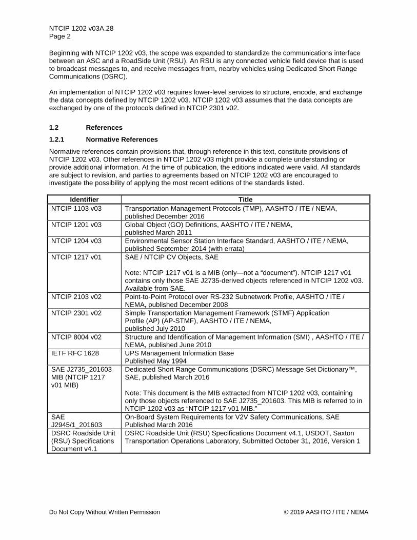
NTCIP 1202 v03A.28 Page 2
Do Not Copy Without Written Permission © 2019 AASHTO / ITE / NEMA
Beginning with NTCIP 1202 v03, the scope was expanded to standardize the communications interface between an ASC and a RoadSide Unit (RSU). An RSU is any connected vehicle field device that is used to broadcast messages to, and receive messages from, nearby vehicles using Dedicated Short Range Communications (DSRC). An implementation of NTCIP 1202 v03 requires lower-level services to structure, encode, and exchange the data concepts defined by NTCIP 1202 v03. NTCIP 1202 v03 assumes that the data concepts are exchanged by one of the protocols defined in NTCIP 2301 v02.
1.2 References 1.2.1 Normative References Normative references contain provisions that, through reference in this text, constitute provisions of NTCIP 1202 v03. Other references in NTCIP 1202 v03 might provide a complete understanding or provide additional information. At the time of publication, the editions indicated were valid. All standards are subject to revision, and parties to agreements based on NTCIP 1202 v03 are encouraged to investigate the possibility of applying the most recent editions of the standards listed.
Identifier Title NTCIP 1103 v03 Transportation Management Protocols (TMP), AASHTO / ITE / NEMA,
published December 2016 NTCIP 1201 v03 Global Object (GO) Definitions, AASHTO / ITE / NEMA,
published March 2011 NTCIP 1204 v03 Environmental Sensor Station Interface Standard, AASHTO / ITE / NEMA,
published September 2014 (with errata) NTCIP 1217 v01 SAE / NTCIP CV Objects, SAE
Note: NTCIP 1217 v01 is a MIB (only—not a “document”). NTCIP 1217 v01 contains only those SAE J2735-derived objects referenced in NTCIP 1202 v03. Available from SAE.
NTCIP 2103 v02 Point-to-Point Protocol over RS-232 Subnetwork Profile, AASHTO / ITE / NEMA, published December 2008
NTCIP 2301 v02 Simple Transportation Management Framework (STMF) Application Profile (AP) (AP-STMF), AASHTO / ITE / NEMA, published July 2010
NTCIP 8004 v02 Structure and Identification of Management Information (SMI) , AASHTO / ITE / NEMA, published June 2010
IETF RFC 1628 UPS Management Information Base Published May 1994
SAE J2735_201603 MIB (NTCIP 1217 v01 MIB)
Dedicated Short Range Communications (DSRC) Message Set Dictionary™, SAE, published March 2016 Note: This document is the MIB extracted from NTCIP 1202 v03, containing only those objects referenced to SAE J2735_201603. This MIB is referred to in NTCIP 1202 v03 as “NTCIP 1217 v01 MIB.”
SAE J2945/1_201603
On-Board System Requirements for V2V Safety Communications, SAE Published March 2016
DSRC Roadside Unit (RSU) Specifications Document v4.1
DSRC Roadside Unit (RSU) Specifications Document v4.1, USDOT, Saxton Transportation Operations Laboratory, Submitted October 31, 2016, Version 1

NTCIP 1202 v03A.28 Page 3
© 2019 AASHTO / ITE / NEMA Do Not Copy Without Written Permission
1.2.2 Other References The following documents and standards may provide the reader with a better understanding of the entire protocol and the relations between all parts of the protocol. However, these documents do not contain direct provisions that are required by NTCIP 1202 v03. At the time of publication, the editions indicated were valid. All standards are subject to revision, and parties to agreements based on NTCIP 1202 v03 are encouraged to investigate the possibility of applying the most recent editions of the standard listed.
Identifier Title IAB STD 16 (RFC 1155) Structure and Identification of Management Information for
TCP/IP-based Internets, M. Rose, K. McCloghrie, May 1990, (RFC 1212) Concise MIB Definitions, M. Rose and K. McCloghrie, March 1991
U.S. Architecture Reference for Cooperative and Intelligent Transportation (ARC-IT)
Architecture Reference for Cooperative and Intelligent Transportation (ARC-IT), USDOT, http://local.iteris.com/arc-it/
ITS Cabinet Standard v01.02.17b
Intelligent Transportation System (ITS) Standard Specification for Roadside Cabinets, v01.02.17b, AASHTO / ITE / NEMA, published November 16 2006
Manual on Uniform Traffic Control Devices (MUTCD)
Manual on Uniform Traffic Control Devices (MUTCD), Federal Highways Administration, 2009 edition with Revision Numbers 1 and 2 Incorporated, May 2012.
NTCIP 2201:2003 Transportation Transport Profile (T2), AASHTO / ITE / NEMA, published September 2005
NTCIP 2202:2001 Transport Profile for Internet (TCP/IP and UDP/IP), AASHTO / ITE / NEMA, published December 2001
Indiana Traffic Signal Hi Resolution Data Logger Enumerations
J. Sturdevant, T. Overman, E. Raamot, R. Deer, D. Miller, D. Bullock, C. Day, T. Brennan Jr., H. Li, A. Hainen and S. Remias, Indiana Department of Transportation and Purdue University, 2012. http://docs.lib.purdue.edu/cgi/viewcontent.cgi?article=1002&context=jtrpdata
OMG Unified Modeling Language Specification, Version 1.5
OMG Unified Modeling Language Specification, Object Management Group, 2003
V2I Hub Interface Control Document
Integrated Vehicle-to-Infrastructure Prototype (IVP), V2I Hub Interface Control Document (ICD) - Final Report March 2017, FHWA JPO
NEMA TS 2-2003 (R2008)
Traffic Controller Assemblies with NTCIP Requirements Version 02.06, with Amendment 3 (Contactor) and Amendment 4 (Flashing Yellow Arrow)
1.2.3 Contact Information 1.2.3.1 Internet Documents Obtain Request for Comment (RFC) electronic documents from several repositories on the World Wide Web, or by “anonymous” File Transfer Protocol (FTP) with several hosts. Browse or FTP to:
www.rfc-editor.org www.rfc-editor.org/repositories.html
for FTP sites, read ftp://ftp.isi.edu/in-notes/rfc-retrieval.txt
1.2.3.2 Architecture Reference for Cooperative and Intelligent Transportation The Architecture Reference for Cooperative and Intelligent Transportation (ARC-IT) may be viewed at:
http://local.iteris.com/arc-it/

NTCIP 1202 v03A.28 Page 4
Do Not Copy Without Written Permission © 2019 AASHTO / ITE / NEMA
ARC-IT is also known as US National ITS Architecture v8.0 and combines the US National ITS Architecture and the Connected Vehicle Reference Implementation Architecture (CVRIA).
1.2.3.3 NTCIP Standards Copies of NTCIP standards may be obtained from:
NTCIP Coordinator National Electrical Manufacturers Association
1300 N.17th Street, Suite 900 Rosslyn, Virginia 22209-3801
www.ntcip.org e-mail: [email protected]
Draft amendments, which are under discussion by the relevant NTCIP Working Group, and amendments recommended by the NTCIP Joint Committee are available.
1.2.3.4 Object Management Group Documents Copies of OMG standards may be obtained electronically from the Object Management Group at:
www.omg.org
1.2.3.5 SAE International Documents Copies of SAE International documents may be obtained from:
SAE International 400 Commonwealth Drive
Warrendale, PA 15096 www.sae.org
1.2.3.6 V2I Hub Document Copies of Integrated Vehicle-to-Infrastructure Prototype (IVP), V2I Hub Interface Control Document (ICD), Final Report – March 2017, may be obtained from the FHWA Open Source Application Development Portal (OSADP):
OSADP
https://www.itsforge.net/
1.3 General Statements <In the opinion of the responsible NTCIP working group, Section 1.3 does not apply in the context of NTCIP 1202 v03.>
1.4 Terms For the purposes of NTCIP 1202 v03, the following terms, definitions, acronyms, and abbreviations apply. Meteorological terms not defined in this section are in accordance with their definitions in the Glossary of Meteorology. Electrical and electronic terms not defined here are used in accordance with their definitions in IEEE Std 100-2000. English words not defined here or in IEEE Std 100-2000 are used in accordance with their definitions in Webster’s New Collegiate Dictionary.

NTCIP 1202 v03A.28 Page 5
© 2019 AASHTO / ITE / NEMA Do Not Copy Without Written Permission
Term Definition
Actuated Signal Controller (ASC)
Any traffic signal controller, regardless if it is a phase-based controller or interval-based controller.
actuation The operation of any type of detector.
advanced preemption time The period of time between the minimum warning time needed for railroad operations and the maximum preemption time required for highway traffic signal operations.
automatic flash Automatic programmed flash mode not caused by manual switch activation or fault condition or startup.
auxiliary function A control that may activate auxiliary functions or outputs in an actuated controller unit.
backup mode Control by local TBC or Interconnect based on absence of master or central command.
barrier A barrier (compatibility line) is a reference point in the preferred sequence of a multi-ring CU at which all rings are interlocked. Note: Barriers assure there is no concurrent selection and timing of conflicting phases for traffic movement in different rings. All rings cross the barrier simultaneously for the selection and timing of phases on the other side.
Basic Safety Message (BSM) The Basic Safety Message (BSM) is used in a variety of applications to exchange safety data regarding vehicle state. Source: SAE J2735_201603
Bus Rapid Transit (BRT) Bus rapid transit (BRT) refers to a system of buses that operate more like a conventional rail system than the traditional local buses. BRT lines can operate in mixed traffic like other bus routes, in reserved bus lanes, or even in segregated rights of way. For the purpose of this document, BRT refers to reserved bus lanes or segregated lanes arriving at a signalized intersection.
call A registration of a demand for right-of-way by traffic (vehicles or pedestrians) to a controller unit.
call, serviceable conflicting A call which: a) Occurs on a conflicting phase not having the right-of-way at the
time the call is placed. b) Occurs on a conflicting phase which is capable of responding to
a call. c) When occurring on a conflicting phase operating in an
occupancy mode, remains present until given its right-of-way.
channel Three circuits of a Monitor Device wired to monitor the green, yellow, and red outputs of the associated load switch position in the Terminal & Facilities. Channel 1 is assumed to monitor Load Switch 1, etc.
check An output from a controller unit that indicates the existence of unanswered call(s).

NTCIP 1202 v03A.28 Page 6
Do Not Copy Without Written Permission © 2019 AASHTO / ITE / NEMA
Term Definition
clear track change interval The yellow change interval following the clear track green interval and preceding the railroad hold intervals. A red clearance interval shall follow the clear track change interval if such an interval follows the normal yellow change interval. (Preemption of Traffic Signals Near Railroad Crossings - ITE, 2006)
computed lane A lane that has a similar geometry and attributes of another lane.
concurrency group A group of phases which describes possible timing combinations. Note: A phase within the group is required to be able to time concurrently with any other phase from another ring contained in the group. For example, in the typical dual-ring eight phase design, phases 1, 2, 5, and 6 form one concurrency group, and phases 3, 4, 7, and 8 form another concurrency group.
concurrent timing A mode of controller unit operation whereby a traffic phase can be selected and timed simultaneously and independently with another traffic phase.
connected device A mobile device, such as a vehicle or smartphone, equipped to broadcast, transmit or receive messages using Dedicated Short Range Communications (DSRC)/ IEEE 802.11/1609.x
Controller Assembly (CA) A complete electrical device mounted in a cabinet for controlling the operation of a traffic control signal display(s).
Controller Unit (CU) A controller unit is that portion of a controller assembly that is devoted to the selection and timing of signal displays.
Coordinated Universal Time (UTC)
UTC is the time standard commonly used across the world. The world’s timing centers have agreed to keep their time scales closely synchronized – or coordinated. This 24-hour time standard is kept using highly precise atomic clocks combined with the Earth’s rotation. UTC is similar to Greenwich Mean Time, but while UTC is a time standard, GMT refers to a time zone (similar to Eastern Standard Time). UTC never changes to account for daylight saving time.
coordination The control of controller units in a manner to provide a relationship between specific green indications at adjacent intersections in accordance with a time schedule to permit continuous operation of groups of vehicles along the street at a planned speed.
coordinator A device or program/routine which provides coordination.
cycle The total time to complete one sequence of signalization around an intersection. In an actuated controller unit, a complete cycle is dependent on the presence of calls on all phases. Note: In a pre-timed controller unit it is a complete sequence of signal indications.
cycle length The time period in seconds required for one complete cycle.

NTCIP 1202 v03A.28 Page 7
© 2019 AASHTO / ITE / NEMA Do Not Copy Without Written Permission
Term Definition
Detector, pedestrian Pedestrian detectors may be pushbuttons or passive detection devices. Passive detection devices register the presence of a pedestrian in a position indicative of a desire to cross, without requiring the pedestrian to push a button. Some passive detection devices are capable of tracking the progress of a pedestrian as the pedestrian crosses the roadway for the purpose of extending or shortening the duration of certain pedestrian timing intervals. Note: Manual of Uniform Traffic Control Devices, FHWA, May 2012
detector, system Any type of vehicle detector used to obtain representative traffic flow information.
detector, vehicle A detector that is responsive to operation by or the presence of a vehicle.
dial The cycle timing reference or coordination input activating same. Dial is also frequently used to describe the cycle.
display map A graphic display of the street system being controlled showing the status of the signal indications and the status of the traffic flow conditions.
dual entry Dual entry is a mode of operation (in a multi-ring CU) in which one phase in each ring is required to be in service. Note: If a call does not exist in a ring when it crosses the barrier, a phase is selected in that ring to be activated by the CU in a predetermined manner.
dwell The interval portion of a phase when present timing requirements have been completed.
dynamic timing pattern A transient timing plan to be used for the next cycle only.
enabled lanes (list) A sequence of lane identifiers for lanes that are identified to be enabled (active) and can be used by the appropriate travelers at the current time.
first coordinated phase The coordinated phase which occurs first within the concurrent group of phases containing the coordinated phase(s) when there are constant calls on all phases.
Flash An operation where one section in each vehicle signal (yellow or red) is alternately on and off with a one second cycle time and a 50 percent duty cycle.
fault monitor state Internal CU diagnostics have determined that the CU device is not in a safe operational state. Note: An output may be asserted to indicate this condition.
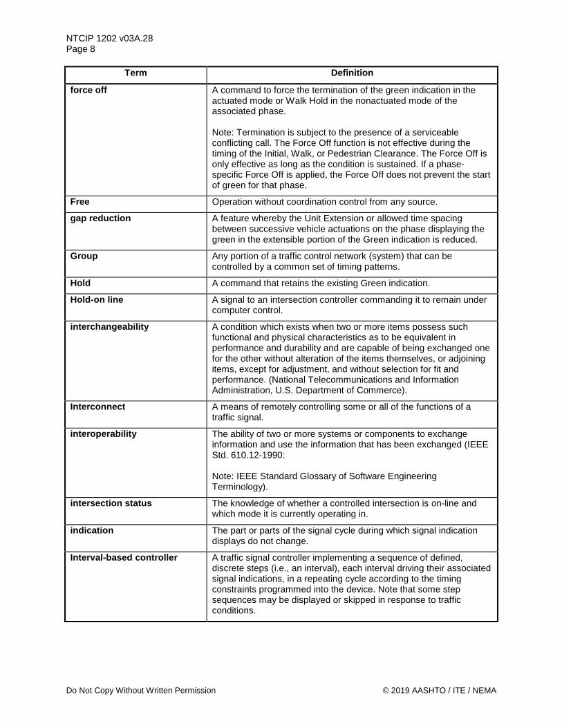
NTCIP 1202 v03A.28 Page 8
Do Not Copy Without Written Permission © 2019 AASHTO / ITE / NEMA
Term Definition
force off A command to force the termination of the green indication in the actuated mode or Walk Hold in the nonactuated mode of the associated phase. Note: Termination is subject to the presence of a serviceable conflicting call. The Force Off function is not effective during the timing of the Initial, Walk, or Pedestrian Clearance. The Force Off is only effective as long as the condition is sustained. If a phase-specific Force Off is applied, the Force Off does not prevent the start of green for that phase.
Free Operation without coordination control from any source.
gap reduction A feature whereby the Unit Extension or allowed time spacing between successive vehicle actuations on the phase displaying the green in the extensible portion of the Green indication is reduced.
Group Any portion of a traffic control network (system) that can be controlled by a common set of timing patterns.
Hold A command that retains the existing Green indication.
Hold-on line A signal to an intersection controller commanding it to remain under computer control.
interchangeability A condition which exists when two or more items possess such functional and physical characteristics as to be equivalent in performance and durability and are capable of being exchanged one for the other without alteration of the items themselves, or adjoining items, except for adjustment, and without selection for fit and performance. (National Telecommunications and Information Administration, U.S. Department of Commerce).
Interconnect A means of remotely controlling some or all of the functions of a traffic signal.
interoperability The ability of two or more systems or components to exchange information and use the information that has been exchanged (IEEE Std. 610.12-1990: Note: IEEE Standard Glossary of Software Engineering Terminology).
intersection status The knowledge of whether a controlled intersection is on-line and which mode it is currently operating in.
indication The part or parts of the signal cycle during which signal indication displays do not change.
Interval-based controller A traffic signal controller implementing a sequence of defined, discrete steps (i.e., an interval), each interval driving their associated signal indications, in a repeating cycle according to the timing constraints programmed into the device. Note that some step sequences may be displayed or skipped in response to traffic conditions.
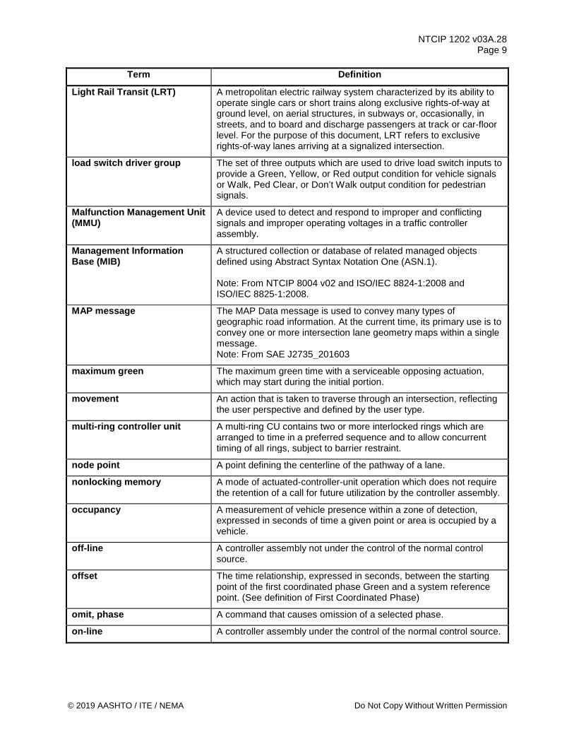
NTCIP 1202 v03A.28 Page 9
© 2019 AASHTO / ITE / NEMA Do Not Copy Without Written Permission
Term Definition
Light Rail Transit (LRT) A metropolitan electric railway system characterized by its ability to operate single cars or short trains along exclusive rights-of-way at ground level, on aerial structures, in subways or, occasionally, in streets, and to board and discharge passengers at track or car-floor level. For the purpose of this document, LRT refers to exclusive rights-of-way lanes arriving at a signalized intersection.
load switch driver group The set of three outputs which are used to drive load switch inputs to provide a Green, Yellow, or Red output condition for vehicle signals or Walk, Ped Clear, or Don’t Walk output condition for pedestrian signals.
Malfunction Management Unit (MMU)
A device used to detect and respond to improper and conflicting signals and improper operating voltages in a traffic controller assembly.
Management Information Base (MIB)
A structured collection or database of related managed objects defined using Abstract Syntax Notation One (ASN.1). Note: From NTCIP 8004 v02 and ISO/IEC 8824-1:2008 and ISO/IEC 8825-1:2008.
MAP message The MAP Data message is used to convey many types of geographic road information. At the current time, its primary use is to convey one or more intersection lane geometry maps within a single message. Note: From SAE J2735_201603
maximum green The maximum green time with a serviceable opposing actuation, which may start during the initial portion.
movement An action that is taken to traverse through an intersection, reflecting the user perspective and defined by the user type.
multi-ring controller unit A multi-ring CU contains two or more interlocked rings which are arranged to time in a preferred sequence and to allow concurrent timing of all rings, subject to barrier restraint.
node point A point defining the centerline of the pathway of a lane.
nonlocking memory A mode of actuated-controller-unit operation which does not require the retention of a call for future utilization by the controller assembly.
occupancy A measurement of vehicle presence within a zone of detection, expressed in seconds of time a given point or area is occupied by a vehicle.
off-line A controller assembly not under the control of the normal control source.
offset The time relationship, expressed in seconds, between the starting point of the first coordinated phase Green and a system reference point. (See definition of First Coordinated Phase)
omit, phase A command that causes omission of a selected phase.
on-line A controller assembly under the control of the normal control source.

NTCIP 1202 v03A.28 Page 10
Do Not Copy Without Written Permission © 2019 AASHTO / ITE / NEMA
Term Definition
overlap A Green display that allows traffic movement during the green indications of and clearance indications between two or more phases.
passage time The time allowed for a vehicle to travel at a selected speed from the detector to the stop line.
pattern A unique set of coordination parameters (cycle value, split values, offset value, and either signal plan or phase sequence). Note: A phase-based timing pattern consists of a cycle length, offset, set of minimum green and maximum green values, force off (determined by splits in some cases), and phase sequence. It also includes specification of phase parameters for minimum or maximum vehicle recall, pedestrian recall, or phase omit. An interval-based timing pattern consists of a cycle length, offset, set of minimum and programmed interval duration values, and a signal plan sequence.
pedestrian clearance interval The first clearance interval for the pedestrian signal following the pedestrian WALK indication.
pedestrian recycle A method of placing a recurring demand for pedestrian service on the movement when that movement is not in its Walk interval.
permissive A time period, during which the CU is allowed to leave the coordinated phase(s) under coordination control to go to other phases.
Personal Safety Message (PSM)
The Personal Safety Message (PSM) is used to broadcast safety data regarding the kinematic state of various types of Vulnerable Road Users (VRU), such as pedestrians, cyclists or road workers. Source: SAE J2735_201603
phase sequence A predetermined order in which the phases of a cycle occur.
phase, active The indicated phase is currently timing. A phase is always active if it is Green or Yellow (Walk or Pedestrian Clear for Pedestrian Phases). It is also active if it is timing Red Clearance. It may be considered active during Red Dwell.
phase, conflicting Conflicting phases are two or more traffic phases which cause interfering traffic movements if operated concurrently.
phase, nonconflicting Nonconflicting phases are two or more traffic phases which do not cause interfering traffic movements if operated concurrently.
phase, pedestrian A traffic phase allocated to pedestrian traffic which may provide a right-of-way pedestrian indication either concurrently with one or more vehicular phases, or to the exclusion of all vehicular phases.
phase, traffic Those green, change and clearance intervals in a cycle assigned to any independent movement(s) of traffic.
phase, vehicular A vehicular phase is a phase which is allocated to vehicular traffic movement as timed by the controller unit.
preempt dwell interval The period of time when the track area is occupied by a tracked vehicle.

NTCIP 1202 v03A.28 Page 11
© 2019 AASHTO / ITE / NEMA Do Not Copy Without Written Permission
Term Definition
preemption The transfer of the normal control of signals to a special signal control mode for the purpose of servicing railroad crossings, emergency vehicle passage, mass transit vehicle passage, and other special tasks, the control of which require terminating normal traffic control to provide the priority needs of the special task.
preemptor A device or program/routine which provides preemption.
priority request The information that describes a need for (signal) priority service based upon user-defined criteria (such as the number of minutes behind schedule, vehicle occupancy levels, vehicle class, etc.). Note: From NTCIP 1211 v02.
progression The act of various controller units providing specific green indications in accordance with a time schedule to permit continuous operation of groups of vehicles along the street at a planned speed.
red clearance interval A clearance interval which may follow the yellow change interval during which both the terminating phase and the next phase display Red signal indications.
red revert Provision within the controller unit to assure a minimum Red signal indication in a phase following the Yellow Change interval of that phase.
referenced lane A lane used to define the attributes of another lane.
rest The interval portion of a phase when present timing requirements have been completed.
right-of-way transfer time While providing preemption, the maximum amount of time needed for the worst case condition, prior to display of the clear track green interval. This includes any railroad or traffic signal control equipment time to react to a preemption call, and any traffic signal green, pedestrian walk and clearance, yellow change and red clearance interval for conflicting traffic.
ring A ring consists of two or more sequentially timed and individually selected conflicting phases so arranged as to occur in an established order.
Roadside Unit (RSU) DSRC devices that serve as the demarcation component between vehicles and other mobile devices and existing traffic equipment. Note: From DSRC Roadside Unit (RSU) Specification Document v4.1
sample A collection of data recorded over an identified period of time.
sequence, interval The order of appearance of signal indications during successive intervals of a cycle.
service request The information that describes a (signal) priority service to be processed by the ASC. Note: From NTCIP 1211 v02
service requestor A traveler requesting signal service or priority using a connected device. The connected device may be an OBE or a smartphone.
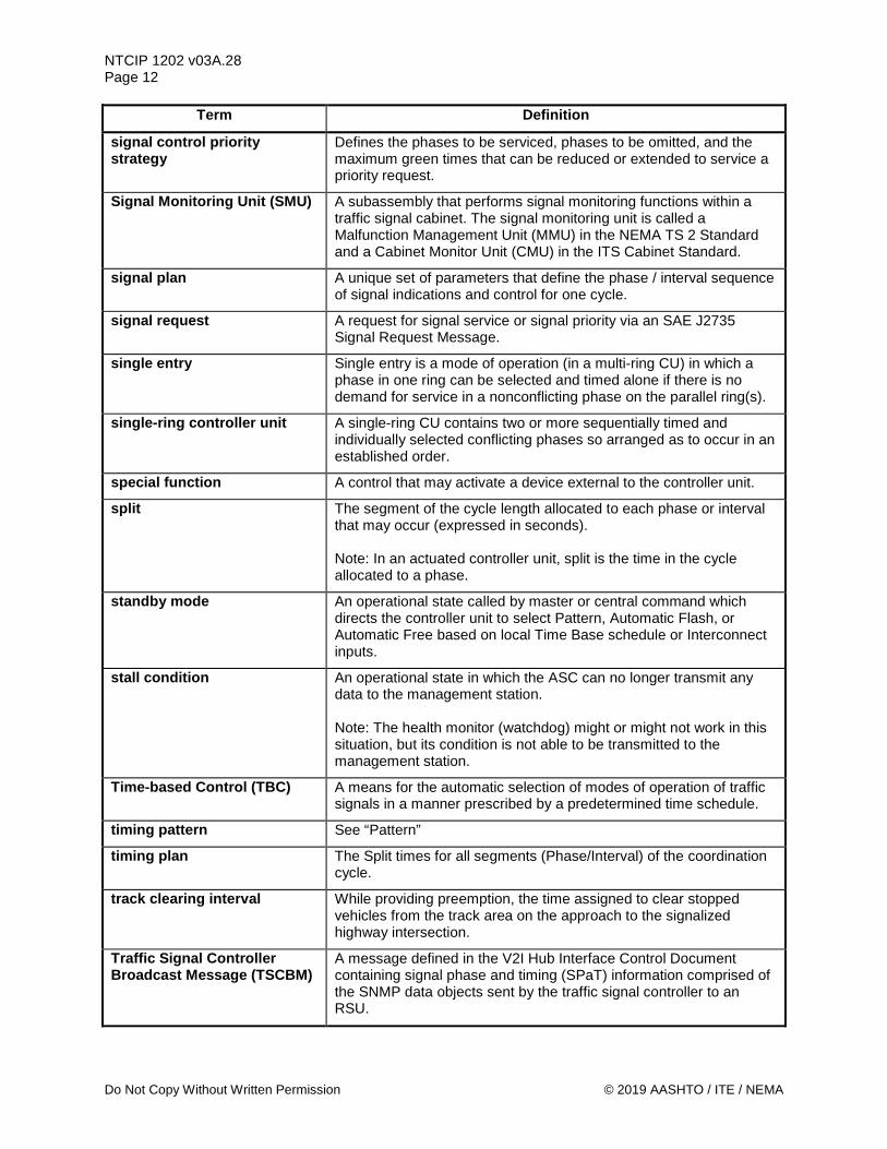
NTCIP 1202 v03A.28 Page 12
Do Not Copy Without Written Permission © 2019 AASHTO / ITE / NEMA
Term Definition
signal control priority strategy
Defines the phases to be serviced, phases to be omitted, and the maximum green times that can be reduced or extended to service a priority request.
Signal Monitoring Unit (SMU) A subassembly that performs signal monitoring functions within a traffic signal cabinet. The signal monitoring unit is called a Malfunction Management Unit (MMU) in the NEMA TS 2 Standard and a Cabinet Monitor Unit (CMU) in the ITS Cabinet Standard.
signal plan A unique set of parameters that define the phase / interval sequence of signal indications and control for one cycle.
signal request A request for signal service or signal priority via an SAE J2735 Signal Request Message.
single entry Single entry is a mode of operation (in a multi-ring CU) in which a phase in one ring can be selected and timed alone if there is no demand for service in a nonconflicting phase on the parallel ring(s).
single-ring controller unit A single-ring CU contains two or more sequentially timed and individually selected conflicting phases so arranged as to occur in an established order.
special function A control that may activate a device external to the controller unit.
split The segment of the cycle length allocated to each phase or interval that may occur (expressed in seconds). Note: In an actuated controller unit, split is the time in the cycle allocated to a phase.
standby mode An operational state called by master or central command which directs the controller unit to select Pattern, Automatic Flash, or Automatic Free based on local Time Base schedule or Interconnect inputs.
stall condition An operational state in which the ASC can no longer transmit any data to the management station. Note: The health monitor (watchdog) might or might not work in this situation, but its condition is not able to be transmitted to the management station.
Time-based Control (TBC) A means for the automatic selection of modes of operation of traffic signals in a manner prescribed by a predetermined time schedule.
timing pattern See “Pattern”
timing plan The Split times for all segments (Phase/Interval) of the coordination cycle.
track clearing interval While providing preemption, the time assigned to clear stopped vehicles from the track area on the approach to the signalized highway intersection.
Traffic Signal Controller Broadcast Message (TSCBM)
A message defined in the V2I Hub Interface Control Document containing signal phase and timing (SPaT) information comprised of the SNMP data objects sent by the traffic signal controller to an RSU.

NTCIP 1202 v03A.28 Page 13
© 2019 AASHTO / ITE / NEMA Do Not Copy Without Written Permission
Term Definition
volume The number of vehicles passing a given point per unit of time.
yellow change interval The first interval following the green interval in which the signal indication for that phase is yellow.
yield A command which permits termination of the green interval.
zone An area in which traffic parameters can be measured and/or traffic data can be generated.
1.5 Abbreviations The abbreviations (acronyms) used in NTCIP 1202 v03, and not defined in Section 1.4 are defined as follows: ADA Americans with Disabilities Act
APS Accessible Pedestrian Signals
BIU Bus Interface Unit
CMU Cabinet Monitor Unit
CV Connected Vehicles
CVRIA Connected Vehicles Reference Implementation Architecture
DSRC Dedicated Short Range Communications
GNSS Global Navigation Satellite System
GPS Global Positioning System
HOV High Occupancy Vehicle
ITS Intelligent Transportation Systems
MAC Media Access Control
MUTCD Manual on Uniform Traffic Control Devices
PRL Protocol Requirements List
RSE Roadside Equipment
RTM Requirements Traceability Matrix
SIU Serial Interface Unit
SNMP Simple Network Management Protocol
SPaT Signal Phase and Timing (as defined by SAE J2735_201603)
VRU Vulnerable Road User

NTCIP 1202 v03A.28 Page 14
Do Not Copy Without Written Permission © 2019 AASHTO / ITE / NEMA
Section 2 Concept of Operations [Normative]
Section 2 defines the user needs that subsequent sections within NTCIP 1202 v03 address. Accepted system engineering processes detail that requirements should only be developed to fulfill well-defined user needs. The first stage in this process is to identify the ways in which the system is intended to be used. In the case of NTCIP 1202 v03, this entails identifying the various ways in which transportation system managers may use ASC information to fulfill their duties. This concept of operations provides the reader with:
a) a detailed description of the scope of NTCIP 1202 v03; b) an explanation of how an ASC is expected to fit into the larger context of an ITS network; c) a starting point in the agency procurement process; and d) an understanding of the perspective of the designers of NTCIP 1202 v03.
Section 2 is intended for all readers of NTCIP 1202 v03, including:
a) transportation system managers b) transportation operations personnel c) transportation engineers d) system integrators e) device manufacturers
For the first three categories of readers, Section 2 is useful to understand how ASC equipment can be used in their system. For this audience, Section 2 serves as the starting point in the procurement process, and enables these readers to become familiar with each feature supported by NTCIP 1202 v03 and determine whether that feature is appropriate for their implementation. If it is, then the procurement specification needs to require support for the feature and all of the mandatory requirements related to that feature. For the last two categories of readers, Section 2 provides a more thorough understanding as to why the more detailed requirements exist later in NTCIP 1202 v03.
2.1 Tutorial [Informative] A concept of operations describes a proposed system from the users' perspective. Typically, a concept of operations is used on a project to ensure that system developers understand users' needs. Within the context of NTCIP standards, a concept of operations documents the intent of each feature for which NTCIP 1202 v03 supports a communications interface. It also serves as the starting point for users to select which features may be appropriate for their project. The concept of operations starts with a discussion of the current situation and issues that have led to the need to deploy systems covered by the scope of NTCIP 1202 v03 and to the development of NTCIP 1202 v03 itself. This discussion is presented in layman's terms such that both the potential users of the system and the system developers can understand and appreciate the situation. The concept of operations then documents key aspects about the proposed system, including:
a) Reference Physical Architecture - The reference physical architecture defines the overall context of the proposed system and defines which specific interfaces are addressed by NTCIP 1202 v03.

NTCIP 1202 v03A.28 Page 15
© 2019 AASHTO / ITE / NEMA Do Not Copy Without Written Permission
The reference physical architecture is supplemented with one or more samples that describe how the reference physical architecture may be realized in an actual deployment.
b) Architectural Needs - The architectural needs section discusses the issues and needs relative to the system architecture that have a direct impact on NTCIP 1202 v03.
c) Features - The features identify and describe the various functions that users may want components of an ASC system to perform. These features are derived from the high-level user needs identified in the problem statement but are refined and organized into a more manageable structure that forms the basis of the traceability tables contained in Section 3 and Annex A.
The architectural needs and features are collectively called user needs. Section 3 uses these user needs in the analysis of the system to define the various functional requirements of an ASC. Each user need shall be traced to one or more functional requirements, and each functional requirement shall be derived from at least one user need. This traceability is shown in the Protocol Requirements List (PRL) as provided in Section 3.3. While NTCIP 1202 v03 is intended to standardize communications across a wide range of deployments, it is not intended to mandate support for every feature for every deployment. Therefore, the PRL also defines each user need and requirement as mandatory, optional, or conditional. The only items marked mandatory are those that relate to the most basic functionality of the device. To obtain a device that meets specific needs, the user first identifies which optional needs are necessary for the specific project. Each requirement identified is then presented in the Requirements Traceability Matrix (RTM) in Annex A, which defines how the requirement is fulfilled through standardized dialogs and data element definitions provided in Section 4 and Section 5. A conformant device may support other user needs, as long as they are conformant with the requirements of NTCIP 1202 v03 and its normative references (see Section 1.2.1). For example, a device may support data that has not been defined by NTCIP 1202 v03; however, when exchanged via one of the NTCIP 2301 v02 protocols, the data shall be properly registered with a valid OBJECT IDENTIFIER under the Global ISO Naming Tree.
Note: Off-the-shelf interoperability and interchangeability can only be obtained by using well-documented user needs, along with their corresponding requirements and design, that are broadly supported by the industry as a whole. Designing a system that uses environments or features not defined in a standard or not typically deployed in combination with one another inhibits the goals of interoperability and interchangeability, especially if the documentation of these user needs is not available for distribution to system integrators. NTCIP 1202 v03 allows implementations to support additional user needs to support innovation, which is constantly needed within the industry, but users should be aware of the risks involved with using such environments or features.
The concept of operations concludes by describing the degree to which security issues have been addressed by the NTCIP 1202 v03 and by providing a description of how NTCIP 1202 v03 relates to the National ITS Architecture and the Connected Vehicle Reference Implementation Architecture.
2.2 Current Situation and Problem Statement [Informative] Transportation system managers use ASCs to control traffic operations on a roadway. ASCs allow different conflicting movements to travel across a roadway in a safe, orderly manner. In a roadway network, ASCs can be coordinated to improve mobility of certain movements, such as along a major arterial. Implemented correctly, ASCs can reduce:
a) the number and severity of accidents b) delays c) stops

NTCIP 1202 v03A.28 Page 16
Do Not Copy Without Written Permission © 2019 AASHTO / ITE / NEMA
d) fuel consumption e) emission of pollutants
There are numerous factors that may affect the operation of an ASC on a roadway. Transportation system managers need to program each ASC to avoid conflicting movements. Conflicting movements are not confined to one specific mode of travel. Travel modes that have movements controllable by an ASC include:
a) Vehicles b) Pedestrians c) Bicycles d) Special vehicles
Special vehicles are vehicles that have one or more characteristics so that an ASC may treat differently than “ordinary” vehicles. Special vehicles may include emergency vehicles or transit vehicles that request preferential (i.e., priority) treatment, or a high occupancy vehicle (HOV) with its own right-of-way (e.g., an HOV-only lane) through the intersection. Each travel mode may have its own minimum clearance requirements that are satisfied to provide sufficient time for traffic to traverse the roadway before a conflicting movement is allowed to move. Transportation system managers can also program an ASC to use inputs from other devices, such as detectors, to measure demand for a specific movement to improve mobility, so that additional time is provided for the movement where the demand exists and less time, if any, is provided for the movement where demand does not exist. An ASC also may be deployed with signal preemption or signal priority capabilities to properly manage movements in special situations. These capabilities, if implemented by the transportation system manager, may allow an emergency vehicle responding to an incident or a railroad at a railroad crossing to preempt the signal and obtain right-of-way. Similarly, signal priority may allow a transit or other fleet vehicle to request preferential treatment through a signalized intersection. The ASC is also expected to have an important role in the connected vehicle environment. In the United States, the connected vehicle environment has three major goals, to improve safety, mobility and the environment. Many of the key applications being developed in support of these goals near signalized intersections involve the infrastructure providing signal phasing and timing information to “connected” devices, such as connected vehicles and “connected” mobile devices, such as a smartphone.
2.3 Reference Physical Architecture [Informative] Section 2.3 represents an overview of what a complete ASC system may look like for a transportation agency, and identifies the specific information exchange paths to be addressed by NTCIP 1202 and related standards.

NTCIP 1202 v03A.28 Page 17
© 2019 AASHTO / ITE / NEMA Do Not Copy Without Written Permission
Figure 1 Reference Physical Architecture - ASC System
The components of the ASC system include:
a) Controller Unit (CU): A host computing platform that is used to manage the traffic signals at an intersection. The CU is responsible for ensuring that the proper signal indications are present on traffic signals. It communicates with the Traffic Management System and other devices through communication ports, and interfaces with the cabinet subsystems to energize the signal heads, read vehicle actuations, drive other auxiliary outputs, and read various inputs such as pedestrian push buttons. It may also communicate with other CUs.
b) Management Station: One or more host computing platforms that manage one or more NTCIP field devices, such as an ASC. The management station is responsible for configuring, monitoring, and controlling the ASC. There may be multiple management stations for a given ASC. A “manager” is a transportation system manager or maintenance person who needs to access information in the ASC through the management station.
c) Traffic Management System: A management station typically located in some type of management center (e.g., a Traffic Management Center) and may be a considerable distance from the ASC. The TMC typically acts as a management station (b) with respect to the ASC.
d) Maintenance Laptop: A computer that a field technician may use on a trip to visit the ASC or a field processor that may be used to access the ASC. It typically acts as a management station (b) with respect to the ASC. It is commonly used to monitor the data reported from the ASC and automatically activate signs or other equipment under certain conditions. It typically plugs directly into the Controller Unit (a).
e) Roadside Unit (RSU): A connected vehicle field device that includes a computing platform running applications and that supports secure communications with connected devices. The RSU receives messages from and transmits messages to nearby connected devices (vehicles or mobile devices) using Dedicated Short Range Communications (DSRC)/ IEEE 802.11/1609.x.

NTCIP 1202 v03A.28 Page 18
Do Not Copy Without Written Permission © 2019 AASHTO / ITE / NEMA
In an ASC System, it may also act as a functional process, called the CV Roadside Process in NTCIP 1202 v03.
f) Detection Subsystems: The units that provide inputs for traffic-actuated control, surveillance, or data collection systems. Detection subsystems include a wide variety of devices to detect the presence and other characteristics of travelers within the range of the intersection. In some instances, such detection devices may be connected directly to the Controller Unit (a) and collect a variety of data such as volume, occupancy, speed, and headway or used for signal priority or preempt detection.
g) Cabinet Subsystems: The controller assembly that consists of the electrical devices in the cabinet for controlling the operation of a traffic control signal display(s). See Figure 2.
Other components shown in Figure 1 include:
h) Connected Vehicle Back Office Systems: Represent centers that manage and support the connected vehicle environment.
Note: The deployment of connected vehicle equipment (such as the RSU) is currently very limited, but is expected to be widespread as more DSRC equipped vehicles are delivered to the marketplace. Also, Figure 1 is only one possible architecture that might be used for the deployment of the infrastructure for connected vehicles, and other architectures are possible.
2.3.1 ASC Characteristics – Cabinet Specifications NTCIP 1202 v03 is intended to address the communications interface between any management station and a controller unit. However, some features defined within NTCIP 1202 v03 apply only to ASCs using a specific transportation cabinet architecture. There are five transportation cabinet architectures that are commonly used in North America.
a) Model 332 Cabinet. A cabinet specification defined in the Caltrans Transportation Electrical Equipment Specification TEES.
b) NEMA TS 1 Cabinet. A cabinet architecture defined in NEMA TS 1-1989 (R2005). c) NEMA TS 2 Type 2 Cabinet. A cabinet architecture defined in the NEMA TS 2-2003 (R2008)
v02.06, Traffic Controller Assemblies with NTCIP Requirements standard. d) NEMA TS 2 Type 1 Cabinet. A cabinet architecture defined in the NEMA TS 2-2003 (R2008)
v02.06, Traffic Controller Assemblies with NTCIP Requirements standard. e) ITS Cabinet. A specification for Intelligent Transportation Systems (ITS) enclosures. The ITS
Cabinet specification defines the subassemblies that provide functionalities within the cabinet.

NTCIP 1202 v03A.28 Page 19
© 2019 AASHTO / ITE / NEMA Do Not Copy Without Written Permission
Figure 2 shows a more detailed look at the components that may be inside a controller assembly.
Cabinet Subsystems
Controller Unit (CU)
Bus/Serial Interface Unit or Parallel IO
External Devices
Detector UnitsLoad SwitchesFlashersPower Distribution
Signal Monitoring
Unit
Auxiliary I/O Devices
Figure 2 Controller Assembly
Cabinet subsystems include:
a) Bus/Serial Interface Unit or Parallel IO: The communications interface between the CU and the cabinet subsystem. It is called the Bus Interface Unit in the NEMA TS 2 Standard and the Serial Interface Unit (SIU) in the ITS Cabinet Standard. Some systems may use a Parallel Input/Output (IO) for the communications interface. It provides the means by which the CU can control the various cabinet devices, and can monitor inputs to provide analysis and data for use by the traffic management algorithms and the Traffic Management System shown in Figure 1.
b) Power Distribution: Provides protected power distribution to the various components and devices within the cabinet.
c) Flashers: Devices used to open and close signal circuits at a repetitive rate. It is typically used to provide a “fail-safe” flashing operation when the Signal Monitoring Unit (e) determines that there is a failure within the cabinet wiring/devices such as shorted load switches, defective cabinet power supplies, or conflicting signal indications.
d) Load Switches: Devices used to switch power to the signal lamps/indications. This typically includes pedestrian signals, traffic signals, auxiliary signs, and other auxiliary devices.
e) Signal Monitoring Unit: A subassembly that performs signal monitoring functions within a traffic signal cabinet. The signal monitoring unit is called a Malfunction Management Unit (MMU) in the NEMA TS 2 Standard and a Cabinet Monitor Unit (CMU) in the ITS Cabinet Standard. When it detects a failure in the operation or a device, it can place the cabinet into the flashing condition using the flashers (c). It also monitors the power line voltage and places the cabinet into the “fail safe” condition when the operating voltage is below configured minimums and holds the cabinet in the “startup” flashing condition upon power restoration to allow the CU to boot and start normal operation.
f) Detector Units: Devices which support the detection of travelers (e.g., vehicles, pedestrians, bicycles, transit vehicles, emergency vehicles). In some cases, the interface allows the CU to monitor the health and gather additional information from the detection subsystems.

NTCIP 1202 v03A.28 Page 20
Do Not Copy Without Written Permission © 2019 AASHTO / ITE / NEMA
In addition, other external devices (equipment) may be mounted inside the controller assembly that are used to provide inputs to the CU or to control traffic flow. Examples of external devices include traffic preemptors, signal priority equipment, or traffic control beacons.
2.3.2 ASC Characteristics – Controller Types Some features defined within NTCIP 1202 v03 may not be applicable to all ASCs - some features are dependent on whether an ASC is one of the following types of controllers. a) Phase-based controller. Phase-based signal controllers refers to a device implementing non-
conflicting signal indications in response to traffic conditions and the timing constraints programmed into the device. A phase controls signal indications for one or more non-conflicting traffic movements and may be actuated by those movement's traffic. In a phase-based, fully actuated system, phases without traffic present may be skipped. Green indication durations may vary between pre-set minimum and maximum values, depending on detected traffic and programmed timing information.
b) Interval-based controller. Interval-based signal controllers refers to a device implementing a sequence of defined, discrete steps (i.e., an interval), each driving the signal indications, in a repeating cycle according to the timing constraints programmed into the device. Note that some step sequences may be displayed or skipped in response to traffic conditions.
Note: Some controllers can operate either as an interval-based controller or a phase-based controller (but not simultaneously). Other types of controllers, such as staged-based controllers, are not addressed by NTCIP 1202 v03. Note: An agency (procurement) specification may include one or both of these types.
Only phase-based controllers are supported by NTCIP 1202 v03.
2.3.3 ASC Characteristics – Connected Vehicle Interface NTCIP 1202 v03 also addresses the communications data exchange between an ASC and a RoadSide Unit (RSU). The RSU is a component of the connected vehicle environment, defined as a "DSRC device that serves as the demarcation component between vehicles and other mobile devices and existing traffic equipment." It is through this communications interface with the RSU that an ASC primarily interacts with the connected vehicle environment. Before the ASC-RSU interface can be effectively addressed, an understanding of the other interfaces between the RSU and connected devices, and the interface among the management station, an ASC and a RSU, is helpful.
Some features defined within NTCIP 1202 v03 for the connected vehicle interface are dependent on the relationship between the ASC and the RSU. The Connected Vehicle Reference Implementation Architecture (CVRIA) implies a logical framework of applications and services that are allocated to the RSU. Therefore, the applications may have needs for information that are provided by the ASC (e.g., information needed to create signal phase and timing (SPaT) messages, status of signal priority requests) or may provide information to the ASC so the ASC may improve safety and mobility at a signalized intersection (e.g., forward a signal priority request, forward location of connected vehicle).
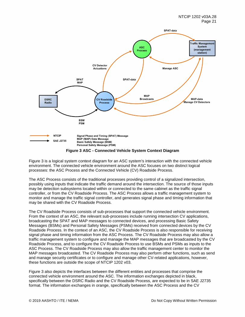
NTCIP 1202 v03A.28 Page 21
© 2019 AASHTO / ITE / NEMA Do Not Copy Without Written Permission
Figure 3 ASC - Connected Vehicle System Context Diagram
Figure 3 is a logical system context diagram for an ASC system's interaction with the connected vehicle environment. The connected vehicle environment around the ASC focuses on two distinct logical processes: the ASC Process and the Connected Vehicle (CV) Roadside Process. The ASC Process consists of the traditional processes providing control of a signalized intersection, possibly using inputs that indicate the traffic demand around the intersection. The source of those inputs may be detection subsystems located within or connected to the same cabinet as the traffic signal controller, or from the CV Roadside Process. The ASC Process allows a traffic management system to monitor and manage the traffic signal controller, and generates signal phase and timing information that may be shared with the CV Roadside Process. The CV Roadside Process consists of sub-processes that support the connected vehicle environment. From the context of an ASC, the relevant sub-processes include running intersection CV applications, broadcasting the SPAT and MAP messages to connected devices, and processing Basic Safety Messages (BSMs) and Personal Safety Messages (PSMs) received from connected devices by the CV Roadside Process. In the context of an ASC, the CV Roadside Process is also responsible for receiving signal phase and timing information from the ASC Process. The CV Roadside Process may also allow a traffic management system to configure and manage the MAP messages that are broadcasted by the CV Roadside Process, and to configure the CV Roadside Process to use BSMs and PSMs as inputs to the ASC Process. The CV Roadside Process may also allow the traffic management center to monitor the MAP messages broadcasted. The CV Roadside Process may also perform other functions, such as send and manage security certificates or to configure and manage other CV-related applications, however, these functions are outside the scope of NTCIP 1202 v03. Figure 3 also depicts the interfaces between the different entities and processes that comprise the connected vehicle environment around the ASC. The information exchanges depicted in black, specifically between the DSRC Radio and the CV Roadside Process, are expected to be in SAE J2735 format. The information exchanges in orange, specifically between the ASC Process and the CV

NTCIP 1202 v03A.28 Page 22
Do Not Copy Without Written Permission © 2019 AASHTO / ITE / NEMA
Roadside Process and between the ASC Process and the traffic management system, are expected to conform to the NTCIP family of standards and are addressed by NTCIP 1202 v03. The information exchanges in cyan, specifically between the CV Roadside Process and the traffic management system, may also conform to the NTCIP family of standards. This interface may be needed to allow a traffic management system to configure the RSU and an implementation may decide to use NTCIP standards or non-NTCIP standards across this interface. If NTCIP is used across this interface, NTCIP 1202 v03 defines the data objects (and dialogs) for information exchanges related to the operation of signalized intersection for user needs and requirements related to traffic signal control. From a physical point of view, two possible physical architectures are considered in NTCIP 1202 v03, defined by where the CV Roadside Process is physically located. In the first architecture, depicted in Figure 4, the CV Roadside Process is located in the RSU, which is a field-hardened computing device within the same or a separate cabinet as the ASC. The DSRC Radio depicted in Figure 4 may be a separate (standalone) physical device or integrated with physical RSU device.
Figure 4 Physical Architecture 1
In the second physical architecture, depicted in Figure 5, has the CV Roadside Process and ASC Process in the same physical device, such as an Advanced Traffic Controller. The CV Roadside Process might be located in a separate processor mounted on a card within the controller assembly.
Figure 5 Physical Architecture 2
2.4 Architectural Needs NTCIP 1202 v03 addresses the interface between an ASC and one or more management stations (e.g., central computers, laptops, RSUs, peer controller units, etc.). A management station needs to monitor the status of the ASC, manage the database in the ASC, and control the ASC. The management station also needs to retrieve data that has been collected by the ASC. After the management station has retrieved

NTCIP 1202 v03A.28 Page 23
© 2019 AASHTO / ITE / NEMA Do Not Copy Without Written Permission
the data of interest, a manager can use the retrieved data to make decisions and initiate other events (such as changes to the ASC timing pattern) to better manage the transportation system. The CV Roadside Process needs data from the ASC about current and future signal phasing and timing information, so the CV Roadside Process can forward this information to connected devices. To enable communications between these components, the transportation system manager needs to establish a communication system that links the ASC with a management station. For some systems, the resources required for communications may be minimal and as such the system may be designed for constant polling; other systems may require significant resources for communicating with the ASC and as such the system may be designed to minimize data exchanges. When deploying an ASC, the system designer needs to consider which of the following operational environments need to be supported. An ASC is expected to operate in the communications environment defined as follows.
2.4.1 Provide Live Data The typical operational environment allows a management station to monitor and control the ASC by issuing requests (e.g., requests to access information, alter information, or control the device). In this environment, the ASC responds to requests from the management station (e.g., through the provision of live data, success/failure notice of information alteration, or success/failure of the command).
2.4.2 Provide Dynamic Object Data Some operational environments have limited data capacity due to limitations in the data rates of the media and/or due to multiple entities or devices sharing the same communications channel. In such environments, dynamic objects provide the capability to group sets of data together so that data can be transmitted more efficiently over telecommunications networks, thereby conserving the limited data capacity of the channel. This capability reduces the upload and download times of data between a management station and an ASC. Several dynamic objects provide users with the capabilities to configure any dynamic objects with any functions in user-definable sequences to be transmitted.
2.4.3 Provide Block Data Some operational environments have limited data capacity due to limitations in the data rates of the media and/or due to multiple entities or devices sharing the same communications channel. In such environments, block data provides the capability to group sets of data together so that data can be transmitted more efficiently over telecommunications networks, thereby conserving the limited data capacity of the channel. This capability reduces the upload and download times of data between a management station and an ASC, or an ASC with another device (e.g., CV Roadside Process). In opposite to dynamic objects, the block objects are ASC-specific, pre-defined blocks of data addressing different functional areas associated with ASCs.
2.4.4 Provide for Log Data Local Storage and Retrieval In a typical operational environment, the ASC needs to provide logged data to the management station for diagnostic purposes, and for operational environments (e.g., dial-up links) that do not have always-on connections. For example, logged data may include the time when the cabinet door is opened. The event log needs to be cleared either in a last-in last-out basis or by the management station because of limited storage space in the ASC.
2.4.5 Provide for Database Management Traffic signal controllers are safety critical devices to manage the traffic movements for vehicles, pedestrians, bicycles, transit, and others are intersecting roadways (or railroad crossings). To ensure that the data downloaded from a central system software to an ASC makes logical sense, consistency checks

NTCIP 1202 v03A.28 Page 24
Do Not Copy Without Written Permission © 2019 AASHTO / ITE / NEMA
on the downloaded need to be performed by the ASC. The user needs to therefore be able to manage the database by being able to open the database to write data, ensure that the downloaded data was received, command the ASC to perform a verification / consistency check the downloaded data, and to close the database to make the downloaded data available to the operational aspects of the ASC. Additionally, should there be any errors, the user needs to be able to determine the source of the error within the downloaded data.
2.4.6 Condition-based Exception Reporting In some operational environments, it may be desirable to have the ASC automatically transmit data to the management station when certain conditions occur. Under this scenario, the manager can program the information to be automatically reported to the management station when a specified condition occurs. An example is a manager wants to know when a cabinet door is opened, when the ASC goes to an error flash condition, or when a phase becomes active; these conditions can be programmed to cause the transmission of the alarm objects thus providing the management station with information regarding the change of state at the ASC cabinet.
2.5 Features Section 2.5 identifies and describes the various features that may be offered by the ASC. It is divided into the following:
a) Manage the ASC Configuration b) Manage Signal Operations c) Manage Detectors d) Manage Connected Vehicles Interface e) Backwards Compatibility Features
2.5.1 Manage the ASC Configuration This section identifies and describes the various features related to managing the configuration of the ASC. It consists of the following features:
a) Retrieve Device Identity b) Manage Communications c) Monitor Cabinet Environment d) Monitor Power e) Retrieve Operational Performance Data f) Manage Auxiliary External Inputs/Outputs g) Manage Database
2.5.1.1 Retrieve Device Identity A manager needs to request and obtain basic information about the ASC. This information consists of its location (latitude and longitude), and the make, model, and version of the device components. The device components can be a hardware, software, or firmware component, and could be a physical or logical entity in nature. This feature allows the manager to verify the identity of the controller in the field and what software or firmware version is installed. This feature also allows the manager to retrieve a unique identifier of the device as provided by the device manufacturer.
2.5.1.2 Manage Communications A manager needs to manage each communications port in the ASC. This feature consists of enabling or disabling the communications ports, and configuring or retrieving the port address (e.g., IP address). This feature allows a manager to disable an unused communications port for security purposes or to reconfigure the ASC for a new communications media.
NTCIP 1202 v03A.28 Page 25
© 2019 AASHTO / ITE / NEMA Do Not Copy Without Written Permission
2.5.1.3 Manage Cabinet Environment A manager may need to monitor the controller cabinet operating environment. This feature allows a manager to monitor for unsafe operating environments for the ASC so proper precautions can be taken. Unsafe operating environment consists of an open controller cabinet door, high cabinet temperatures, or an indication that the cabinet fan has turned on.
2.5.1.4 Monitor Power A manager may need to monitor the power for the ASC. This feature assists the manager in determining whether the power sources for the ASC cabinet are suspect and need maintenance or whether the intersection is operating on an alternate power source. For example, some ASCs use AC power for its battery.
2.5.1.5 Retrieve Operational Performance Data A manager may need to retrieve operational data from the ASC for the analysis of the signal timing efficacy. The operational data consists of frequent snapshots of signal operations data and detector data and allows the manager to view the temporal relationship between signal indications and traveler arrivals. An example of this operational data is the Indiana Traffic Signal Hi Resolution Data Logger Enumerations. This feature provides a manager with the information to evaluate the performance of signal operations, such as the quality of progression of traffic along arterials, or measuring the amount of unused green time during a cycle. The manager may wish to monitor the operational data or store the operational data in a log for retrieval at a later time.
2.5.1.6 Manage Auxiliary External Inputs/Outputs A manager may need to monitor and control auxiliary external devices (i.e., non-signal control) through the ASC. This feature allows the manager to activate auxiliary external devices or functions that may be tied to other transportation operational needs. For example, the ASC may be co-located with a trail-blazing sign utilized for special events and not associated with traffic signal operations.
2.5.1.7 Manage Database A manager needs to manage the configuration and version of the database in the ASC. The database configuration and version allow a manager to determine if the ASC has the correct and expected version of the database.
2.5.2 Manage Signal Operations This section identifies and describes the various features to monitor and control traffic signal operations. It consists of the following features:
a) Manage Signal Configuration b) Monitor Signal Operations Status c) Control Signal Operations
2.5.2.1 Manage Signal Configuration 2.5.2.1.1 Manage Controller Startup Functions A manager needs to retrieve and configure the startup capabilities and functions of the ASC. This feature allows the manager to define the startup times upon powerup, set the backup time, set the minimum clearance times for the ASC.

NTCIP 1202 v03A.28 Page 26
Do Not Copy Without Written Permission © 2019 AASHTO / ITE / NEMA
2.5.2.1.2 Manage Phase Configurations For a phase-based controller, a manager needs to retrieve and configure the phases for the ASC. This consists of setting the minimum durations, maximum durations, clearance times, allowable concurrent phases, and other phase-related features and options for all travel modes (vehicles, pedestrians, bicycles, special vehicles).
2.5.2.1.3 Manage Coordination Configurations A manager needs to retrieve and configure the coordination modes for the ASC. This consists of the allowable operational, correction and force modes, and coordination point within a phase to be used for signal coordination.
2.5.2.1.4 Manage Timing Patterns A manager needs to retrieve and configure the timing patterns stored in the ASC. Each timing pattern defines a cycle length, splits, offsets and the phase sequences. The manager may also specify a default timing pattern.
2.5.2.1.5 Manage Splits Configurations A manager needs to retrieve and configure the splits stored in the ASC. The information for each set of splits consists of the phase assignment, the coordinated phase, the split time, and the split mode.
2.5.2.1.6 Manage Ring Configurations For a phase-based controller, a manager needs to retrieve and configure the rings in the ASC. Each ring defines the sequence of phases for that ring.
2.5.2.1.7 Manage Channel Configurations A manager needs to retrieve and configure the channel parameters in the ASC. Each channel consists of the control source, the type of phase the channel is controlling (e.g., vehicle phase, pedestrian phase, bicycle phase, overlap), and its flash and dimming characteristics.
2.5.2.1.8 Manage Overlap Configurations For a phase-based controller, a manager may need to retrieve and configure the overlap functions in the ASC. For each overlap, this consists of the type of overlap operation, the included phases, the modifier phases, any overlap extensions and clearance times.
2.5.2.1.9 Manage Preempt Configurations A manager may need to retrieve and configure the preempts in the ASC. Preempts are used to service special needs at an intersection, such as for a railroad crossing or emergency vehicles responding to an incident. This feature allows the manager to retrieve and configure the minimum durations, phase settings, outputs and clearance times whenever a preempt signal is detected, how the controller enters into and exits out of preemption and to define the priority of different preempt inputs into the ASC. This feature also allows a manager to configure the ASC to enable or disable the preempt under certain conditions, such as time-of-day, or to configure the ASC to select alternate exit strategies based on input conditions.
NTCIP 1202 v03A.28 Page 27
© 2019 AASHTO / ITE / NEMA Do Not Copy Without Written Permission
2.5.2.1.10 Manage Timing Pattern Scheduler A manager may need to retrieve and configure the scheduler in the ASC to implement a timing pattern based on time. This feature allows the manager to configure the ASC to implement timing patterns for both controllers based on calendar days, days of the week and/or times of day.
2.5.2.1.11 Manage Action Scheduler A manager may need to retrieve and configure the scheduler in the ASC to perform a function or a group of functions. The action scheduler allows a manager to activate an output, configure the ASC (e.g., max2), configure the ASC log, or program the condition-based exception reporting based on calendar days, days of the week and/or times of day. For example, the manager may program the action scheduler to activate the special function output every weekday when a nearby school is in session and configure the ASC to operate in non-actuated mode during the same period of time. The manager may also configure the log not to record actuations, and to program the condition-based exception reporting not to report actuations during that same period of time.
2.5.2.1.12 Manage I/O Mapping A manager may need to retrieve and configure the input/output mapping in the ASC. This feature allows the manager to change the input and outputs for an ASC so unused inputs or outputs, as defined by a standard specification, can be used and configured as needed. This feature also allows the manager to reset the input/output mapping to a default configuration, and configure the conditions when changes to input/output mapping can be accepted by the ASC.
2.5.2.1.13 Manage Intra-Cabinet Communications Configuration A manager may need to retrieve and configure the ASC’s intra-cabinet communications port. For NEMA TS 2 type controllers, this is the NEMA TS 2 Port 1 in the ASC and allows a manager to indicate if a device is present on Port 1. For controllers in an ITS Cabinet, this is Serial Bus 1.
2.5.2.1.14 Manage ADA Support A manager may need to retrieve and configure the ASC to support Accessible Pedestrian Signals (APS). This feature enables an ASC to provide information about pedestrian signal timing to pedestrians.
2.5.2.2 Monitor Signal Operations Status This feature allows a manager to monitor the traffic signal operations and status of an ASC. It consists of the following sub-features.
a) Determine Controller Health b) Determine Mode of Operation c) Monitor Signal Indication d) Monitor Phase Status e) Monitor Ring Status f) Monitor Channel Status g) Monitor Overlap Status h) Monitor Preempt Input State i) Monitor Preempt State j) Monitor Special Function Outputs k) Monitor Timebase Action Status l) Monitor Intra-Cabinet Communications Configuration
NTCIP 1202 v03A.28 Page 28
Do Not Copy Without Written Permission © 2019 AASHTO / ITE / NEMA
2.5.2.2.1 Determine Controller Health A manager needs to monitor the health of the ASC. This feature allows a manager to determine if the essential functions and elements of the ASC are operating properly. ASC system error conditions and faults to be monitored are processor stall conditions (timeouts), memory faults, task (i.e., process) failures, communication timeouts or errors from a management station, and suspect power problems. ASC operational error conditions and faults to be monitored are conflicts, cycle failures, and coordination failures.
2.5.2.2.2 Determine Mode of Operation This feature allows a manager needs to determine the current mode of operation in the ASC. It consists of the following sub-features.
2.5.2.2.2.1 Monitor Unit-wide General Operations A manager needs to determine if the ASC as a unit is operational, provides unit-wide control status information, and monitors other unit-wide parameters such as automatic detector calls, dimming, and interconnect status.
2.5.2.2.2.2 Monitor Flashing A manager needs to determine if the ASC is in a flashing condition and the reason for the flashing condition. If a condition is detected in the controller assembly that may comprise public safety, the ASC generally reverts to a flash condition. Thus the manager needs to determine if the cause of a flash condition is normal (e.g., the ASC was commanded to flash) or if a safety critical condition was detected.
2.5.2.2.2.3 Monitor Current Timing Pattern A manager needs to retrieve information about the timing pattern, mode of operation and its source (e.g., program entry, time base control, system interface, etc…) running in the ASC. The status needs to indicate the current timing pattern and mode of operation in effect, and the programmed timing pattern and mode of operation (what should be in effect).
2.5.2.2.2.4 Monitor Current Cycle A manager needs to retrieve information about the current timing pattern cycle in the ASC. This consists of the current split, its coordination state, the duration of time since the current cycle started, and the duration of time before the current phase ends.
2.5.2.2.3 Monitor Signal Indication A manager needs to retrieve the status of each signal indication configured in the ASC. This feature indicates if each signal indication is on, off, flashing or dimmed. This feature allows a manager to view the signal indications on a map.
2.5.2.2.4 Monitor Phase Status For a phase-based controller, a manager needs to retrieve the status of each phase configured in the ASC. This feature indicates if each phase is active or not (including clearance intervals) and if there is an active vehicle or pedestrian call. This feature also indicates which phases are expected to be active after the termination of an active phase. This feature allows a manager to observe and review signal operations.

NTCIP 1202 v03A.28 Page 29
© 2019 AASHTO / ITE / NEMA Do Not Copy Without Written Permission
2.5.2.2.5 Monitor Ring Status For a phased-based controller, a manager needs to retrieve the status of each ring output configured in the ASC. This feature allows a manager to determine what state (minimum green, extension, yellow change, red clearance, red rest, etc…) and interval the ring is currently in.
2.5.2.2.6 Monitor Channel Status A manager needs to retrieve the status of each channel output configured in the ASC. This feature allows a manager to determine if each channel output is red, yellow or green, and the current measured voltages and electrical current.
2.5.2.2.7 Monitor Overlap Status A manager needs to retrieve the status of each overlap configured in the ASC. This feature allows a manager to determine if each overlap is red, yellow or green.
2.5.2.2.8 Monitor Preempt Input State A manager may need to retrieve the preempt input state for each preempt input configured in the ASC. This feature allows a manager to determine whether an input signal is active on each preempt input of an ASC.
2.5.2.2.9 Monitor Preempt State A manager may need to retrieve the status of the preempt state for each preempt input configured in the ASC. For each preempt input, this indicates if the preempt service has started, is being delayed, is linked to another preempt sequence, is overriding another preempt sequence, is being overridden by another preempt sequence, the preempt interval (e.g., in dwell) and if the preempt is exiting out of preempt service.
2.5.2.2.10 Monitor Special Function Outputs A manager may need to retrieve if each special function output configured in the ASC is active. For example, an ASC near a school may use its special function outputs to turn on a flashing beacon to indicate a lower speed limit when a timing pattern associated with traffic arriving and leaving the school are in effect.
2.5.2.2.11 Monitor Timebase Action Status A manager may need to retrieve which timebase action entry is currently in effect in the ASC.
2.5.2.2.12 Monitor Intra-Cabinet Communications Configuration A manager may need to retrieve if the ASC’s intra-cabinet communications port is online. For NEMA TS 2 type controllers, this is the NEMA TS 2 Port 1 in the ASC. For traffic signal controllers in an ITS Cabinet, this is Serial Bus 1.
2.5.2.3 Control Signal Operations This feature allows a manager to control the signal operation of an ASC. It consists of the following sub-features:
a) Control ASC-wide General Operations b) Command Timing Pattern c) Phase Requests d) Activate Preempt

NTCIP 1202 v03A.28 Page 30
Do Not Copy Without Written Permission © 2019 AASHTO / ITE / NEMA
e) Control Ring Operations f) Activate Special Function Output g) Control Scheduler h) Control Frame 40 i) Activate Action Plan j) Remote Manual Control
2.5.2.3.1 Control ASC-wide General Operations A manager needs to control ASC-wide operational features within the ASC such as external minimum recalls, automatic detector calls, dimming, interconnect, and enabling/disabling remote commands to the ASC.
2.5.2.3.2 Command Timing Pattern A manager needs to command the ASC to a mode of operation, activate a timing pattern or activate a signal plan. This feature allows a manager to command the ASC to a standby mode, to free mode, or to flash, and to establish the system reference point.
2.5.2.3.3 Phase Requests For a phased-based controller, a manager may need to control the duration and inclusion of phases for the current (signal) cycle of an ASC. This feature consists of the capability to omit phases, hold phases, force phases off, and to place calls.
2.5.2.3.4 Activate Preempt A manager may need to activate a preempt input configured in the ASC. This feature allows a manager to force the ASC to request a preempt sequence state for diagnostic purposes or during special events.
2.5.2.3.5 Control Ring Operations A manager may need to control ring operations of an ASC. This feature allows a manager to stop the ring timing, to activate a force off, or force the ring to rest in red.
2.5.2.3.6 Activate Special Function Output A manager may need to activate a special function output configured in an ASC. This special function output may be used to activate other devices, such as flashing beacon or a blank out sign associated with a timing pattern.
2.5.2.3.7 Control Frame 40 For NEMA TS 2 type controllers, a manager needs to enable or disable Frame 40 messages from the ASC to a device at the Port 1 address. Frame 40 is used to poll the secondary stations for a secondary to secondary message exchange.
2.5.2.3.8 Activate Action Plan A manager may need to activate a pre-defined group of functions configured in an ASC. This feature allows a manager to command the ASC to perform a group of functions. The functions consist of allowing a manager to activate an output, configure the ASC (e.g., max2), configure the ASC log, or program the condition-based exception reporting.

NTCIP 1202 v03A.28 Page 31
© 2019 AASHTO / ITE / NEMA Do Not Copy Without Written Permission
2.5.2.3.9 Remote Manual Control A manager needs to command the ASC to remotely advance the signal controller through the phases or intervals. This feature allows a manager to remotely and manually control a signal controller. Examples of when a manager may wish to manually control an intersection would be for special events, such as sporting events, parades and large concerts, where traffic congestion is far in excess of normal volumes.
2.5.3 Manage Detectors Section 2.5.3 identifies and describes the various features to monitor and control the detector inputs to the ASC. A detector may be used to identify demand for signal service. The user needs to monitor and control detector inputs consist of the following features:
a) Manage Detector Configuration b) Monitor Detector Status c) Monitor Detector Health d) Control Detectors e) Manage Detector Data
2.5.3.1 Manage Detector Configuration A manager needs to retrieve and configure the detectors connected to the ASC. This feature allows a manager to define the travel mode being detected (vehicle, pedestrian, transit, and bicycle), select phase assignments, define capabilities, and define the criteria for detector faults. The criteria for a detector fault consists of the amount of time between detector actuations, amount of time with continuous actuations, and excessive actuations over a period of time.
2.5.3.2 Monitor Detector Status A manager needs to monitor activations for detectors configured in the ASC. This feature allows a manager to determine the presence of vehicles, pedestrians or other travelers on the roadway.
2.5.3.3 Monitor Detector Health A manager needs to monitor the health of the detectors configured in the ASC. This feature allows a manager to determine if the detectors are operating correctly or if a fault has been detected so maintenance personnel can be dispatched to repair the detectors if necessary.
2.5.3.4 Control Detectors A manager needs to control a detector configured in the ASC. This feature allows a manager to clear a detector fault and place the detector back in service, and to activate a call on a detector.
2.5.3.5 Manage Detector Data A manager may need to set up the ASC to collect data from detectors configured in the ASC. This feature allows a manager to retrieve reports from the ASC on the data measured by the detectors over a user-defined period. This data consists of volumes, occupancies, and speeds as appropriate.
2.5.4 Manage Connected Vehicles Interface This section identifies and describes the various features that support the interface with a CV Roadside Process in a connected vehicle environment. The connected vehicle environment is expected to use the SAE J2735 - Dedicated Short Range Communications (DSRC) Message Set Dictionary as the information standard. Several messages in SAE J2735 are pertinent to ASCs and are addressed within NTCIP 1202 v03. These messages are:
NTCIP 1202 v03A.28 Page 32
Do Not Copy Without Written Permission © 2019 AASHTO / ITE / NEMA
a) Signal Phase and Timing (SPaT) Message. A broadcasted message providing signal phase
and timing information for one or more ASC indicating the state of each permitted intersection maneuver and when an active maneuver terminates. The current signal status is also sent. This message is intended for connected devices in the broadcast vicinity of an ASC.
b) MAP Message. A broadcasted message providing map information, such as intersection roadway geometry including lane information and allowable traveler (e.g., vehicles, pedestrians, bicycles, special vehicles) maneuvers, as well as the mapping between the SPAT data provided by the ASC and the intersection roadway geometry.
c) Basic Safety Message. A broadcasted message providing “basic” information about the location and movements of a “connected” vehicle, including its current location, speed, acceleration, and direction of travel.
d) Personal Safety Message. A broadcasted message providing "basic" information about the location and movements of a "connected" mobile device carried by a Vulnerable Road User (VRU), such as a pedestrian, bicyclist or road worker, or integrated in a device used by the VRU, such as a bicycle or wheelchair.
The features offered by an ASC to support the connected vehicle environment are organized by interface:
a) the interface between a management station and the ASC; b) the interface between a management station and the CV Roadside Process; and c) the interface between the ASC and the CV Roadside Process.
2.5.4.1 Connected Vehicle Manager: Management Station – ASC Interface The following subsections identify and describe the various features that may be offered between a management station and an ASC. These features are:
a) Manage RSU Interface b) Manage RSU Interface Watchdog c) Manage Signal Phase and Timing Data d) Exchange Connected Devices Data for Operational Performance Data
2.5.4.1.1 Manage RSU Interface A manager needs to retrieve and configure the interface between the ASC and an RSU. This feature allows a manager to configure operational control information of how often information is exchanged between the ASC and an RSU.
2.5.4.1.2 Manage RSU Interface Watchdog A manager needs to retrieve and configure an RSU watchdog within the ASC. This feature allows the ASC to monitor the period of time elapsed between data exchanges across an ASC and RSU interface. If the time elapsed exceeds a configured threshold, the ASC hardware is reset to clear the potential stall condition.
2.5.4.1.3 Manage Signal Phase and Timing Data Some of the key applications that have been developed within the connected vehicle environment are related to intersection safety. For signalized intersections, this involves an RSU broadcasting SPaT messages, as defined by SAE J2735, to connected vehicles in the vicinity. Some of the data in the SPaT message originates from the ASC, so the ASC needs to exchange this data with the RSU. However, a manager in a traffic management center needs to monitor what data is being provided to the RSU to broadcast to connected devices. This feature allows the manager to manage and view the contents of the signal phase and timing data that the ASC is exchanging with the RSU, so the RSU may generate and broadcast SPaT messages, as defined by SAE J2735_201603.

NTCIP 1202 v03A.28 Page 33
© 2019 AASHTO / ITE / NEMA Do Not Copy Without Written Permission
2.5.4.1.4 Exchange Connected Devices Data for Operational Performance Data A manager needs to retrieve data about connected devices traversing the roadway in the vicinity of the ASC. This data consists of frequent snapshots about connected devices in the vicinity of the ASC and allows the manager to view the temporal relationship between signal indications and traveler arrivals. This feature allows a manager to integrate phase and timing information with data from connected devices to produce performance metrics related to intersection demand, safety, and operations.
2.5.4.2 Connected Vehicle Manager: Management Station – CV Roadside Process Interface The following subsections identify and describe the various features that may be offered between a management station and a CV Roadside Process. These features are: a) Manage Roadway Geometrics Information b) Manage Movement Configuration for Connected Devices c) Manage Collection of Connected Devices Data d) Monitor Broadcasted MAP Messages e) Monitor Broadcasted SPAT Messages
2.5.4.2.1 Manage Roadway Geometrics Information A manager needs to retrieve and configure the roadway geometry plans in the CV Roadside Process. Each roadway geometry plan defines the pathways where movements are permitted at the intersection when that roadway geometry plan is in effect. This feature allows a manager to provide a CV Roadside Process with information needed to broadcast the MAP message to connected devices. This information includes the intersection identifier, the geographic path of each travel lane approaching and exiting the intersection, and the width of each pathway.
2.5.4.2.2 Manage Movement Configuration for Connected Devices A manager needs to retrieve and configure the CV Roadside Process with a mapping between the signal indications configured in the ASC with the permitted movements that are broadcasted in a SPaT (and MAP) message by the CV Roadside Process. This feature defines the association between each signal indication configured in the ASC with a permitted pathway, possibly defined in the roadway geometry plan in effect. This feature allows the manager to provide a CV Roadside Process with information that may be needed to broadcast the MAP (and SPaT) message to connected devices. This information may consist of the intersection identifier, the permitted movement for each pathway defined in the roadway geometry plan, and the association between a signal indication and a pathway.
Note: This user need is designed around the concept that the signal operations for an ASC depend on “awareness” of each signal indication to movement mapping that the ASC is programmed for, and each mapping is assigned an identifier. When the mapping in effect changes, the ASC informs the CV Roadside Process by indicating a new identifier is in effect (See 2.5.4.2.8). So, an identifier for each signal indication to movement mapping is required.
2.5.4.2.3 Manage Collection of Connected Devices Data A manager needs to configure a CV Roadside Process to forward the presence of connected devices on the roadway to the ASC. This feature allows a manager to configure the CV Roadside Process to use information in the BSMs and PSMs received by the CV Roadside Process as a call for actuated movements or to determine the demand for specific movements. This feature also allows a CV Roadside Process to filter the information exchanged with the ASC, based on the travel mode (e.g., vehicle, pedestrian, bicycle, special vehicle) or an event. Information extracted from the BSMs and PSMs includes location of the connected device, direction of travel, speed, and travel mode (e.g., vehicle, pedestrian, bicycle, special vehicle), direction and the location of the connected device.
NTCIP 1202 v03A.28 Page 34
Do Not Copy Without Written Permission © 2019 AASHTO / ITE / NEMA
2.5.4.2.4 Monitor Broadcasted MAP Messages A manager needs to monitor the data included in a MAP data message broadcasted to connected devices. The MAP data message is expected to be broadcasted in concert with the broadcast of the SPAT message to connected devices in the vicinity of a signalized intersection. This feature allows the manager to view the contents of the MAP data message being broadcasted by the CV Roadside Process in support of the SPaT message that is also being broadcasted.
2.5.4.2.5 Monitor Broadcasted SPAT Messages A manager needs to monitor the data included in a SPAT message broadcasted to connected devices. The SPAT message is expected to broadcast in concert with the broadcast of the MAP data message to connected devices in the vicinity of a signalized intersection. This feature allows the manager to view the contents of the SPAT message broadcasted by the CV Roadside Process.
2.5.4.3 Connected Vehicle Manager: ASC - CV Roadside Process Interface The following subsections identify and describe the various features that may be offered between an ASC and a CV Roadside Process. These features are: a) Exchange Current and Next Movement Information b) Exchange Next Occurrence of a Movement c) Exchange Presence of Connected Devices d) Exchange Roadway Geometrics Information
2.5.4.3.1 Exchange Current and Next Movement Information An ASC needs to exchange with a CV Roadside Process what the current state of each movement is and when that state will change. This feature allows the ASC to exchange information about when each state of each movement starts and ends. The CV Roadside Process uses this information for its safety, mobility and environmental applications and to broadcast SPaT messages to connected vehicles and mobile devices. An ASC operating in actuated mode might only be able to provide a time period when an active movement is to terminate. An ASC also may not be able to provide about the next active movement until the end of a current active movement.
2.5.4.3.2 Exchange Next Occurrence of a Movement An ASC needs to exchange with a CV Roadside Process what the future states of each movement will be and when those states will start and end. One of the applications envisioned for the connected vehicle environment is Connected Eco-Driving. This application provides customized real-time driving advice to drivers so that they can adjust their driving behavior to save fuel and reduce emissions (from the Connected Vehicles Reference Implementation Architecture (CVRIA)). This may include a CV application in the CV Roadside Process providing recommendations for an optimal speed to equipped vehicles so vehicles arrive at the intersection when the signal indication for their desired movement is green, reducing fuel consumption and emissions created when a vehicle unnecessarily brakes and accelerates.
2.5.4.3.3 Exchange Presence of Connected Devices An ASC needs to exchange with a CV Roadside Process the presence of connected devices on the roadway around the ASC. This feature allows the ASC to exchange with the CV Roadside Process information that can be used as a call for actuated movements or to determine the demand for specific movements. The Basic Safety Message and the Personal Safety Message are the primary sources of presence information that are received by a CV Roadside Process located near the ASC and then exchanged with the ASC.

NTCIP 1202 v03A.28 Page 35
© 2019 AASHTO / ITE / NEMA Do Not Copy Without Written Permission
2.5.4.3.4 Exchange Roadway Geometrics Information An ASC needs to exchange with a CV Roadside Process the roadway geometry plan that is currently in effect at the intersection. Each roadway geometry plan may define the pathways where movements are permitted at the intersection when that roadway geometry plan is in effect. A pathway may be a vehicle lane, a pedestrian crossing, a bicycle lane, or a transit right of way. This feature allows the ASC to exchange with the CV Roadside Process when the roadway geometry plan in effect in the ASC has changed. The ASC uses this information to confirm that the roadway geometry plan is compatible with the signal operations timing plan in effect. For example, an ASC may be programmed to use signal timing plans with an intersection roadway geometry with one-way approaches into the intersection. However, if the intersection roadway has been changed to two-way traffic, the ASC needs to confirm that the signal timing plan in effect is still compatible with the new roadway geometry plan that the CV Roadside Process is broadcasting to travelers.
2.5.4.3.5 Exchange Movement Configuration An ASC needs to exchange with the CV Roadside Process the signal indication to movement mapping currently in effect at the intersection. Each signal indication to movement mapping defines what movements are permitted for each pathway at the intersection when that signal indication to movement mapping is in effect. This feature allows the ASC to exchange with the CV Roadside Process when the signal indication to movement mapping in the ASC has changed, such as when travel in a lane has been reversed. For example, an ASC with a reversible lane traversing the intersection may have two signal indication to movement mappings, one signal indication to movement mapping to associate a signal indication to the reversible lane and the adjacent lane in the same direction of travel, and a second signal indication to movement mapping when the permitted vehicle movement in the reversible lane is in the opposite direction to the adjacent lane (the subject signal indication is associated only to the adjacent lane).
2.5.5 Backward Compatibility Features The following sub-features were modified within NTCIP 1202 v02 and needed to be specifically spelled out to achieve backward compatibility for certain features within an ASC conforming to NTCIP 1202 v03.
2.5.5.1 Backward Compatible with NTCIP 1202 v01 A newer transportation system component may need to communicate with other components that conform to NTCIP 1202 v01.
2.5.5.2 Backward Compatible with NTCIP 1202 v02 A newer transportation system component may need to communicate with other components that conform to NTCIP 1202 v02. However, NTCIP 1202 v03 is fully backward compatible with NTCIP 1202 v02.
2.6 Security Section 2.6 identifies and describes the various security features that may be offered by the ASC. It consists of the following sub-features:
a) Manage Authentication b) Manage Accessibility c) Manage Users d) Log User Access

NTCIP 1202 v03A.28 Page 36
Do Not Copy Without Written Permission © 2019 AASHTO / ITE / NEMA
Note: Users should be aware that at the time of this publication, NTCIP 1202 v03 uses SNMP v1 as referenced by NTCIP 1103 v03, a normative reference. Later versions of SNMP provide additional security but are out of scope for this particular project; thus, an agency is encouraged to consider security implications.
2.6.1 Manage Authentication A manager needs to retrieve and configure the ASC to authenticate requests from a manager. This feature allows a manager to authenticate users and passwords in the ASC.
2.6.2 Manage Accessibility A manager needs to retrieve and configure the ASC to limit access to specific information in the ASC based on the permissions assigned by the manager.
2.6.3 Manage Users A manager needs to retrieve and configure a user’s profile in the ASC. Each user profile consists of a user, its password and its access rights.
2.6.4 Log User Access A manager needs to retrieve and configure the ASC to log when and what requests were made by a manager. This feature allows a manager to track who made what changes to the ASC security configuration, or commanded the ASC to perform a security-related function. This feature is only accessible by a system administrator.
2.7 Operational Policies and Constraints It is the operational policy of some agencies that authorized personnel is/are present at the physical location of the ASC, before an ASC accepts a change to the configuration of the ASC. This operational policy is usually enforced by requiring that the door of the controller cabinet containing the ASC is open.
2.8 Relationship to the ITS National Architecture [Informative] Architecture Reference for Cooperative and Intelligent Transportation, known as ARC-IT, combines the National ITS Architecture (NITSA) and the Connected Vehicle Reference Implementation Architecture (CVRIA). NTCIP 1202 v03 addresses many ARC-IT flows associated with the operation of an ASC. NTCIP 1202 v03 addresses fourteen (14) ARC-IT flows between a Traffic Management Center (TMC) and a Traffic Signal Controller (ITS Roadway Equipment (IRE)) that are associated with the operation of an ASC. These flows are:
a) Mixed Use Safety Warning Control: Configuration and control of equipment that monitors and manages mixed-use crossings and provides visual displays and warnings to drivers when non-motorized users are occupying a cross walk or other mixed-use path crossing.
b) Mixed Use Safety Warning Status: Current operational status and state of pedestrian crossings and other mixed-use path crossing warning systems.
c) Rail Crossing Control Data: Data required for Highway-Rail Intersection (HRI) information transmitted at railroad grade crossings and within railroad operations.
d) Rail Crossing Request: A request for highway-rail intersection status or a specific control request intended to modify HRI operation.
e) Rail Crossing Status: Status of the highway-rail intersection equipment including both the current state or mode of operation and the current equipment condition.

NTCIP 1202 v03A.28 Page 37
© 2019 AASHTO / ITE / NEMA Do Not Copy Without Written Permission
f) Right-of-Way Request Notification: Notice that a request has occurred for signal prioritization, signal preemption, pedestrian call, multi-modal crossing activation, or other sources for right-of-way requests.
g) Signal Control Commands: Control of traffic signal controllers or field masters including clock synchronization.
h) Signal Control Device Configuration: Data used to configure traffic signal control equipment including local controllers and system masters.
i) Signal Control Plans: Traffic signal timing parameters including minimum green time and interval durations for basic operation and cycle length, splits, offset, phase sequence, etc. for coordinated systems.
j) Signal Control Status: Operational and status data of traffic signal control equipment including operating conditions and current indications.
k) Signal Fault Data: Faults from traffic signal control equipment. l) Signal System Configuration: Data used to configure traffic signal systems including
configuring control sections and mode of operation (time-based or traffic responsive). m) Traffic Flow: Raw and/or processed traffic detector data which allows derivation of traffic flow
variables (e.g., speed, volume, and density measures) and associated information (e.g., congestion, potential incidents). This flow includes the traffic data and the operational status of the traffic detectors.
n) Traffic Sensor Control: Information used to configure and control traffic sensor systems such as inductive loop detectors and machine vision sensors.
NTCIP 1202 v03 also addresses fifteen (15) ARC-IT flows between a Traffic Signal Controller, represented as an ITS Roadway Equipment (IRE), and an RSU, represented as a Connected Vehicle Roadside Equipment (CVRE). These flows are:
a) Arriving Train Information: Information for a train approaching a highway-rail intersection that may include direction and allow calculation of approximate arrival time and closure duration.
b) Conflict Monitor Status: A control flow that supports failsafe operation in the event that a conflict is detected that requires the RSE to enter a failsafe operating mode.
c) Intersection Control Status: Status data provided by the traffic signal controller including phase information, alarm status, and priority/preempt status.
d) Intersection Infringement Info: Vehicle path information sent by a vehicle that is violating the stop bar at an intersection. This flow includes the vehicle's position, heading, speed, acceleration, transmission, steering-wheel angle, braking status, size information, and trajectory.
e) Intersection Status Monitoring: Current signal phase and timing information for all lanes at a signalized intersection. This flow identifies monitoring of communications by a receiver at the intersection to support monitoring for conflicts between actual signal states and RSE communications about those states.
f) ITS Roadway Equipment Information: This general flow represents the information provided to the RSU by local field devices. This includes intersection status, environmental sensor data, and signage data.
g) Mixed Use Crossing Status: Current pedestrian and other non-motorized user locations including an indication of whether the call button has been activated, the current state of the mixed-use crossing signal, and information indicating whether non-motorized users are currently occupying the cross walk.
h) Personal Location Information: Pedestrian, bicyclist, and other non-motorized user locations at an intersection as detected and reported by an RSE.
i) Signal Preemption Request: Direct request for preemption to a traffic signal controller that results in preemption of the current control plan and grants right-of-way to the requesting vehicle. This flow identifies the required phase and timing of the preemption. This flow may also cancel the preemption request (e.g., when the requesting vehicle clears the intersection).
j) Signal Priority Service Request: A service request for vehicle priority issued to a traffic signal controller that results in green extension or other accommodation for the priority vehicle, within the current signal timing plan. The request includes the desired time and duration of service. This flow also allows the RSE to cancel a previously issued request for priority.

NTCIP 1202 v03A.28 Page 38
Do Not Copy Without Written Permission © 2019 AASHTO / ITE / NEMA
k) Signal Service Request: A call for service or extension for a signal control phase that is issued by the RSE for connected vehicles approaching an intersection and/or pedestrians at a crosswalk. This flow identifies the desired phase and service time.
l) Track Status: Current status of the wayside equipment and notification of an arriving train. m) Traffic Gap Information: Measured gap to the next approaching vehicle per lane and direction of
travel. n) Traffic Situation Data: Current, aggregate traffic data collected from connected vehicles that can
be used to supplement or replace information collected by roadside traffic detectors. It includes raw and/or processed reported vehicle speeds, counts, and other derived measures. Raw and/or filtered vehicle control events may also be included to support incident detection.
o) Vehicle Entries and Exit: Information exchanged between an RSE and ITS Roadway Equipment (ASC) that supports detection of non-equipped vehicles in an automated lane, low emissions zone, or other facility where V2I communications is used to monitor vehicles at entry or exit points. This exchange also supports identification of non-equipped vehicles where an RSE is used for payment collection. This generic exchange can be implemented by any approach that compares vehicle detections with V2I communications by the RSE to identify vehicles that are not equipped or are otherwise unable to communicate with the RSE.

NTCIP 1202 v03A.28 Page 39
© 2019 AASHTO / ITE / NEMA Do Not Copy Without Written Permission
Section 3 Functional Requirements [Normative]
Section 3 defines the Functional Requirements based on the user needs identified in the Concept of Operations (see Section 2). Section 3 includes: a) A tutorial b) Protocol Requirements List (PRL) – A Functional Requirement is a requirement of a given function
and therefore is only required to be implemented if the associated functionality (e.g., user need) is selected through the use of the PRL. The PRL also indicates which of the items are mandatory, conditional, or optional. The PRL can be used by procurement personnel to specify the desired features of an ASC system or can be used by a manufacturer to document the features supported by their implementation.
c) Architectural Requirements – These are requirements related to the architectural needs defined in Section 2.4.
d) Data Exchange and Operational Environment Requirements – These are requirements related to the features identified in Section 2.5 that can be realized through a data exchange. For example, this includes the requirement to be able to monitor what signal indications are active.
e) Supplemental Non-communications Requirements – These are additional requirements derived from the Concept of Operations that do not fall into one of the above two categories. For example, they include requirements related to performance requirements.
f) Generic Requirements – There are requirements that are generic to all NTCIP field devices. For example, clock synchronization of devices is a requirement that is considered generic to all NTCIP devices. These requirements can be found in Annex G.
Section 3 is intended for all readers, including: a) Transportation operations managers b) Transportation operations personnel c) Transportation engineers d) System integrators e) Device manufacturers For the first three categories of readers, Section 3 is useful in understanding the details that NTCIP 1202 v03 requires of an ASC. For these readers, Section 3.3.3 is particularly useful in preparing procurement specifications and assist in mapping the various rows of this table to the more detailed text contained within the other sections. For the last two categories of readers, this section is useful to fully understand what is required of equipment meeting this interface standard. The table in Section 3.3.3 may be used to document the capabilities of their implementations.
3.1 Tutorial [Informative] This Functional Requirements section defines the formal requirements that are intended to satisfy the user needs identified in Section 2. This is achieved through the development of a PRL that traces each user need to one or more requirements defined in this section. The details of each requirement are then presented following the PRL. The functional requirements are presented in three broad categories as follows:
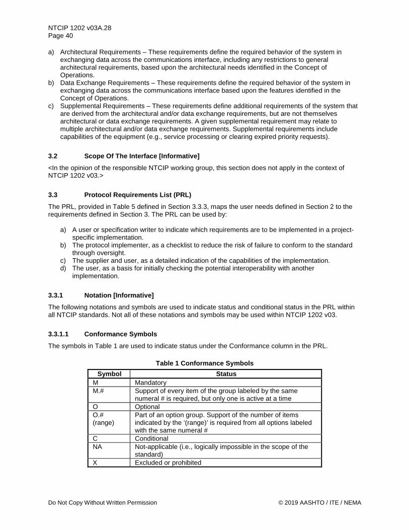
NTCIP 1202 v03A.28 Page 40
Do Not Copy Without Written Permission © 2019 AASHTO / ITE / NEMA
a) Architectural Requirements – These requirements define the required behavior of the system in exchanging data across the communications interface, including any restrictions to general architectural requirements, based upon the architectural needs identified in the Concept of Operations.
b) Data Exchange Requirements – These requirements define the required behavior of the system in exchanging data across the communications interface based upon the features identified in the Concept of Operations.
c) Supplemental Requirements – These requirements define additional requirements of the system that are derived from the architectural and/or data exchange requirements, but are not themselves architectural or data exchange requirements. A given supplemental requirement may relate to multiple architectural and/or data exchange requirements. Supplemental requirements include capabilities of the equipment (e.g., service processing or clearing expired priority requests).
3.2 Scope Of The Interface [Informative] <In the opinion of the responsible NTCIP working group, this section does not apply in the context of NTCIP 1202 v03.>
3.3 Protocol Requirements List (PRL) The PRL, provided in Table 5 defined in Section 3.3.3, maps the user needs defined in Section 2 to the requirements defined in Section 3. The PRL can be used by:
a) A user or specification writer to indicate which requirements are to be implemented in a project-specific implementation.
b) The protocol implementer, as a checklist to reduce the risk of failure to conform to the standard through oversight.
c) The supplier and user, as a detailed indication of the capabilities of the implementation. d) The user, as a basis for initially checking the potential interoperability with another
implementation.
3.3.1 Notation [Informative] The following notations and symbols are used to indicate status and conditional status in the PRL within all NTCIP standards. Not all of these notations and symbols may be used within NTCIP 1202 v03.
3.3.1.1 Conformance Symbols The symbols in Table 1 are used to indicate status under the Conformance column in the PRL.
Table 1 Conformance Symbols Symbol Status
M Mandatory M.# Support of every item of the group labeled by the same
numeral # is required, but only one is active at a time O Optional O.# (range)
Part of an option group. Support of the number of items indicated by the ‘(range)’ is required from all options labeled with the same numeral #
C Conditional NA Not-applicable (i.e., logically impossible in the scope of the
standard) X Excluded or prohibited

NTCIP 1202 v03A.28 Page 41
© 2019 AASHTO / ITE / NEMA Do Not Copy Without Written Permission
The O.# (range) notation is used to show a set of selectable options (e.g., O.2 (1..*) would indicate that one or more of the option group 2 options shall be implemented). Two character combinations are used for dynamic requirements. In this case, the first character refers to the static (implementation) status, and the second refers to the dynamic (use); thus, "MO" means "mandatory to be implemented, optional to be used."
3.3.1.2 Conditional Status Notation The predicate notations in Table 2 may be used.
Table 2 Conditional Status Notation Predicate Notation <predicate>: This notation introduces a single item that is conditional on the <predicate>. <predicate>:: This notation introduces a table or a group of tables, all of which are
conditional on the <predicate>. (predicate) This notation introduces the first occurrence of the predicate. The feature
associated with this notation is the base feature for all options that have this predicate in their conformance column.
The <predicate>: notation means that the status following it applies only when the PRL states that the feature or features identified by the predicate are supported. In the simplest case, <predicate> is the identifying tag of a single PRL item. The <predicate> notation may precede a table or group of tables in a section or subsection. When the group predicate is true then the associated section shall be completed. The symbol <predicate> also may be a Boolean expression composed of several indices. "AND," "OR," and "NOT" shall be used to indicate the Boolean logical operations. The predicates used in NTCIP 1202 v03 map to the sections indicated in Table 3.
Table 3 Predicate Mapping to NTCIP 1202 v03 Section Predicate Section 332 2.3.1.a AdvGrWarn 3.5.2.1.2.1.47 AdvRdWarn 3.5.2.1.2.1.49 AntiStream H.1.1.10.6.6 ASC 3.5.4.3.b BackupUD 3.5.2.1.1.3 Bicycle 3.5.2.1.2.1.53 Coord 2.5.2.1.3 Channel 2.5.2.1.7 Computed 3.5.4.2.1.1.7.1 CV 2.5.4 Detector 2.5.3.1 DetZoneOut 3.5.4.2.3.2.1 Dimming 3.5.2.2.2.7 DST H.1.1.5.6 Humidity 3.5.1.3.6 ITS 2.3.1.e Overlap 2.5.2.1.8 MvtConflict 3.5.4.1.3.6.4.4 MvtQueue 3.5.4.1.3.6.4.1 Perform 2.5.1.5 PhsCtrl 2.5.2.3.3

NTCIP 1202 v03A.28 Page 42
Do Not Copy Without Written Permission © 2019 AASHTO / ITE / NEMA
Predicate Section Power 2.5.1.4 Preempt 2.5.2.1.9 preemptExit 3.5.2.1.9.1.15 preemptQueue 3.5.2.1.9.1.16.3 RestrictClass 3.5.4.2.1.1.9 Ring 2.5.2.1.6 RSU 3.5.4.3.a Scheduler 2.5.2.1.10 SpdAdvice 3.5.4.1.3.6.5.1 SpecialFunc 2.5.2.2.10 Speed 3.5.3.1.1.1.3 SpeedLimit 3.5.4.2.1.1.6.8 Temp 3.5.1.3.5 TimeZone H.1.1.5.5 Transit 3.5.2.1.2.1.63 Traps 2.4.6 TrapAck H.1.1.10.6.1 TrapQueue H.1.1.10.6.3 TS1 2.3.1.b TS2-1 2.3.1.d TS2-2 2.3.1.c Unit 2.5.2.2.2.1 UPS 3.5.1.4.3 Watch H.1.1.10.2.2
3.3.1.3 Support Column Symbols The Support column in the PRL can be used by a procurement specification to identify the required features for the given procurement or by an implementer to identify which features have been implemented. In either case, the user circles the appropriate answer (Yes, No, or N/A) in the support column:
Table 4 Support Column Entries Entry Identifier Yes Supported by the implementation. No Not supported by the implementation. N/A Not applicable
3.3.2 Instructions for Completing the PRL [Informative] In the ‘Support’ column, each response shall be selected either from the indicated set of responses (for example: Yes / No / NA), or it shall reference additional items that are to be attached (for example, list of traffic signal controllers to be supported by an implementation). If a conditional requirement is inapplicable, use the Not Applicable (NA) choice. If a mandatory requirement is not satisfied, exception information shall be supplied by entering a reference Xi, where i is a unique identifier, to an accompanying rationale for the non-conformance. When the status is expressed as a two-character combination (as defined in 3.3.1.1 above), the response shall address each element of the requirement; e.g., for the requirement "mo," the possible compliant responses are "yy" or "yn."
Note: A specification can allow for flexibility in a deliverable by leaving the selection in the Support column blank for a given row.

NTCIP 1202 v03A.28 Page 43
© 2019 AASHTO / ITE / NEMA Do Not Copy Without Written Permission
3.3.2.1 Conformance Definition To claim "Conformance" to NTCIP 1202 v03, the vendor shall minimally fulfill the mandatory requirements as identified in the PRL table (see Table 5).
Note: The reader and user of NTCIP 1202 v03 are advised that 'conformance' to NTCIP 1202 v03 should not be confused with 'compliance' to a specification. NTCIP 1202 v03 is as broad as possible to allow a very simple ASC implementation to be 'conformant' to NTCIP 1202 v03. An agency specification needs to identify the requirements of a particular project and needs to require the support of those requirements. A specification writer is advised to match the requirements of a project with the corresponding standardized requirements defined in NTCIP 1202 v03 to achieve interoperability. This means that functions and requirements defined as 'optional' in NTCIP 1202 v03 might need to be selected in a specification (in effect made 'mandatory' for the project-specific specification).
A conformant device may offer additional (optional) features, as long as they are conformant with the requirements of NTCIP 1202 v03 and the standards it references (e.g., NTCIP 1201 v03 and NTCIP 2301 v02). For example, to claim conformance to additional features, an implementation shall conform to all of the mandatory and selected optional requirements that trace to the subject user needs in the PRL, AND shall fulfill the requirement by using all of the dialogs and data elements traced to the subject requirement in the Requirements Traceability Matrix (RTM) in Annex A. A device may also support data that has not been defined by NTCIP 1202 v03; however, when exchanged via one of the NTCIP 2301 v02 protocols, the data shall be properly registered with a valid OBJECT IDENTIFIER under the Global ISO Naming Tree.
Note: Off-the-shelf interoperability and interchangeability can only be obtained through well-documented features broadly supported by the industry as a whole. Designing a system that uses features not defined in a standard or not typically deployed in combination with one another inhibits the goals of interoperability and interchangeability, especially if the documentation of these features is not available for distribution to system integrators. Standards allow the use of additional features to support innovation, which is constantly needed within the industry; but users should be aware of the risks involved with using such features.
To claim "Conformance" to NTCIP 1202 v03, an ASC device shall be provided with a MIB that contains all non-NTCIP-standardized (including custom, proprietary and vendor-, agency-, or implementation-specific) object and block definitions. Object and block definitions contained in the MIB shall:
a) use the ASN.1 notation and conventions used in NTCIP 1202 v03 standardized object and block definitions,
b) include non-NTCIP-standardized enumerations, and c) include meaningful, human-understandable, English language DESCRIPTION fields including
descriptions of the object and all supported values. In addition, to claim "Conformance" to NTCIP 1202 v03, an ASC device shall use the NTCIP 1202 v03 standardized objects to manage NTCIP 1202 v03 functionality. Non-NTCIP-standardized objects may be used to manage NTCIP 1202 v03 functionality only if NTCIP 1202 v03 standardized objects for the same functions are also supported. ASC devices or systems attempting to manage, configure, or monitor an NTCIP 1202 v03 standardized object shall not be required to use proprietary objects for NTCIP 1202 v03 functionality.
3.3.3 Protocol Requirements List (PRL) Table In addition to the Conformance column and the Support column, which were discussed in Sections 3.3.1 and 3.3.2, the additional columns in the PRL table are the User Need ID and User Need columns, FR ID and Functional Requirements columns and the Additional Specifications column.

NTCIP 1202 v03A.28 Page 44
Do Not Copy Without Written Permission © 2019 AASHTO / ITE / NEMA
a) User Need ID – the number assigned to the user need statement. The user needs are defined
within Section 2, and the PRL is based upon the user need sections within that Section. b) User Need – a short descriptive title identifying the user need. c) FR ID – the number assigned to the functional requirement statement. The requirements are
defined within Section 3, and the PRL references the traces from user needs to these requirements.
d) Functional Requirement – a short descriptive title identifying the functional requirement. e) Additional Specifications – identifies other requirements to satisfy, including user selectable range
values. The "Additional Specifications" column may (and should) be used by a procurement specification to provide additional notes and requirements for the product to be procured or may be used by an implementer to provide any additional details about the implementation. In some cases, default text already exists in this field, which the user should complete to fully specify the equipment. However, additional text can be added to this field as needed to fully specify a feature.
Note: Visit www.ntcip.org for information on the availability of electronic copies of the PRL.

NTCIP 1202 v03A.28 Page 45
© 2019 AASHTO / ITE / NEMA Copy Per PRL Distribution Permission
Table 5 Protocol Requirements List (PRL)
Protocol Requirements List (PRL) User Need
ID User Need FR ID Functional Requirement Conformance Support Additional Specifications
2.3 Reference Physical Architecture [Informative] 2.3.1 ASC Characteristics – Cabinet Specifications M Yes 2.3.1.a (332) Model 332 Cabinet O.1 (1) Yes / No
2.3.1.b (TS1) NEMA TS 1 Cabinet O.1 (1) Yes / No
2.3.1.c (TS2-2) NEMA TS 2 Type 2 Cabinet O.1 (1) Yes / No
2.3.1.d (TS2-1) NEMA TS 2 Type 1 Cabinet O.1 (1) Yes / No
2.3.1.e (ITS) ITS Cabinet O.1 (1) Yes / No
2.3.2 ASC Characteristics – Controller Types M Yes 2.3.2.a Phase-based controller M Yes
2.3.2.b Interval-based controller NA NA Interval-based controllers are not supported by NTCIP 1202 v03
2.4 Architectural Needs 2.4.1 Provide Live Data M Yes
3.4.1.1 Retrieve Data M Yes 3.4.1.2 Deliver Data M Yes 3.4.1.3 Explore Data M Yes
3.6.1 Response Time for Requests M Yes
The Response Time for all requests shall be ___ milliseconds (5-500: Default=25).
2.4.2 Provide Dynamic Object Data O Yes / No
H.1.1.9.1.1 Configure Dynamic Object Persistence Time M Yes / NA
H.1.1.9.1.2 Configure Dynamic Object Configuration ID M Yes / NA
H.1.2.5.1.1 Determine Dynamic Object Persistence Time M Yes / NA

NTCIP 1202 v03A.28 Page 46
Copy Per PRL Distribution Permission © 2019 AASHTO / ITE / NEMA
Protocol Requirements List (PRL) User Need
ID User Need FR ID Functional Requirement Conformance Support Additional Specifications
H.1.2.5.1.2 Determine Dynamic Object Configuration ID M Yes / NA
H.1.2.5.2.1.1 Monitor Incoming and Outgoing STMP Packet Exchanges M Yes / NA
H.1.2.5.2.1.2 Monitor Incoming and Outgoing STMP Packet Types M Yes / NA
H.1.2.5.2.2.1 Monitor Incoming and Outgoing STMP Error Exchanges - Too Big Error
M Yes / NA
H.1.2.5.2.2.2 Monitor Incoming and Outgoing STMP Error Exchanges - No Such Name
M Yes / NA
H.1.2.5.2.2.3 Monitor Incoming and Outgoing STMP Error Exchanges - Bad Value M Yes / NA
H.1.2.5.2.2.4 Monitor Incoming and Outgoing STMP Error Exchanges - Read-Only M Yes / NA
H.1.2.5.2.2.5 Monitor Incoming and Outgoing STMP Error Exchanges - General Error
M Yes / NA
2.4.3 Provide Block Data O Yes / No
3.5.2.1.14.1.1.1 Configure Block Object Get Control - Phase Data O Yes / No
3.5.2.1.14.1.1.2 Configure Block Object Get Control - Vehicle Detector Data O Yes / No
3.5.2.1.14.1.1.3 Configure Block Object Get Control - Pedestrian Detector Data O Yes / No
3.5.2.1.14.1.1.4 Configure Block Object Get Control - Pattern Data O Yes / No
3.5.2.1.14.1.1.5 Configure Block Object Get Control - Split Data O Yes / No
3.5.2.1.14.1.1.6 Configure Block Object Get Control - Time Base Data O Yes / No
3.5.2.1.14.1.1.7 Configure Block Object Get Control - Preempt Data O Yes / No
3.5.2.1.14.1.1.8 Configure Block Object Get Control - Sequence Data O Yes / No

NTCIP 1202 v03A.28 Page 47
© 2019 AASHTO / ITE / NEMA Copy Per PRL Distribution Permission
Protocol Requirements List (PRL) User Need
ID User Need FR ID Functional Requirement Conformance Support Additional Specifications
3.5.2.1.14.1.1.9 Configure Block Object Get Control - Channel Data O Yes / No
3.5.2.1.14.1.1.10 Configure Block Object Get Control - Overlap Data O Yes / No
3.5.2.1.14.1.1.11 Configure Block Object Get Control - Port 1 Data O Yes / No
3.5.2.1.14.1.1.12 Configure Block Object Get Control - Schedule Data O Yes / No
3.5.2.1.14.1.1.13 Configure Block Object Get Control - Day Plan Data O Yes / No
3.5.2.1.14.1.1.14 Configure Block Object Get Control - Event Configuration Data O Yes / No
3.5.2.1.14.1.1.15 Configure Block Object Get Control - Event Class Data O Yes / No
3.5.2.1.14.1.1.16 Configure Block Object Get Control - Dynamic Object Configuration Data O Yes / No
3.5.2.1.14.1.1.17 Configure Block Object Get Control - Dynamic Object Owner Data O Yes / No
3.5.2.1.14.1.1.18 Configure Block Object Get Control - Dynamic Object Status Data O Yes / No
3.5.2.1.14.1.1.19 Configure Block Object Get Control - Miscellaneous ASC Data O Yes / No
3.5.2.1.14.1.1.20 Configure Block Object Get Control - Version 3 Additional Phase Data O Yes / No
3.5.2.1.14.1.1.21 Configure Block Object Get Control -
Version 3 Additional Vehicle Detector Data
O Yes / No
3.5.2.1.14.1.1.22 Configure Block Object Get Control -
Version 3 Vehicle Detector Volume Occupancy Report Data
O Yes / No
3.5.2.1.14.1.1.23 Configure Block Object Get Control -
Version 3 Additional Pedestrian Detector Data
O Yes / No
3.5.2.1.14.1.1.24 Configure Block Object Get Control - Version 3 Pedestrian Detector Report Data
O Yes / No

NTCIP 1202 v03A.28 Page 48
Copy Per PRL Distribution Permission © 2019 AASHTO / ITE / NEMA
Protocol Requirements List (PRL) User Need
ID User Need FR ID Functional Requirement Conformance Support Additional Specifications
3.5.2.1.14.1.1.25 Configure Block Object Get Control - Version 3 Pedestrian Push Button Configuration Data
O Yes / No
3.5.2.1.14.1.1.26 Configure Block Object Get Control - Version 3 Additional Pattern Data O Yes / No
3.5.2.1.14.1.1.27 Configure Block Object Get Control - Version 3 Additional Split Data O Yes / No
3.5.2.1.14.1.1.28 Configure Block Object Get Control - Version 3 Additional Preempt Data O Yes / No
3.5.2.1.14.1.1.29 Configure Block Object Get Control - Version 3 Preempt Queue Delay Data O Yes / No
3.5.2.1.14.1.1.30 Configure Block Object Get Control - Version 3 Additional Channel Data O Yes / No
3.5.2.1.14.1.1.31 Configure Block Object Get Control - Version 3 Additional Overlap Data O Yes / No
3.5.2.1.14.1.1.32 Configure Block Object Get Control - Communications Port Definition Data O Yes / No
3.5.2.1.14.1.1.33 Configure Block Object Get Control –
Ethernet Communications Port Definition Data
O Yes / No
3.5.2.1.14.1.1.34 Configure Block Object Get Control –
SIU Communications Port 1 Definition Data
O Yes / No
3.5.2.1.14.1.1.35 Configure Block Object Get Control -
Version 3 Additional Miscellaneous ASC Data
O Yes / No
3.5.2.1.14.1.1.36 Configure Block Object Get Control –
User-Defined Backup Timer Content Data
O Yes / No
3.5.2.1.14.1.1.37 Configure Block Object Get Control – ASC Location Data O Yes / No
3.5.2.1.14.1.1.38 Configure Block Object Get Control – Global Set ID Data O Yes / No
3.5.2.1.14.1.1.39 Configure Block Object Get Control – ASC Environmental Monitoring Data O Yes / No

NTCIP 1202 v03A.28 Page 49
© 2019 AASHTO / ITE / NEMA Copy Per PRL Distribution Permission
Protocol Requirements List (PRL) User Need
ID User Need FR ID Functional Requirement Conformance Support Additional Specifications
3.5.2.1.14.1.1.40 Configure Block Object Get Control –
ASC Cabinet Temperature Sensor Data
O Yes / No
3.5.2.1.14.1.1.41 Configure Block Object Get Control – ASC Cabinet Humidity Sensor Data O Yes / No
3.5.2.1.14.1.1.42 Configure Block Object Get Control - I/O Input Mapping Data O Yes / No
3.5.2.1.14.1.1.43 Configure Block Object Get Control - I/O Input Mapping Status Data O Yes / No
3.5.2.1.14.1.1.44 Configure Block Object Get Control – I/O Output Mapping Data O Yes / No
3.5.2.1.14.1.1.45 Configure Block Object Get Control - I/O Output Mapping Status Data O Yes / No
3.5.2.1.14.1.1.46 Configure Block Object Get Control - I/O Mapping Description Data O Yes / No
3.5.2.1.14.1.1.47 Configure Block Object Get Control –
Connected Vehicle Configuration Data
O Yes / No
3.5.2.1.14.1.1.48 Configure Block Object Get Control –
Connected Vehicle RSU Port Configuration Data
O Yes / No
3.5.2.1.14.1.1.49 Configure Block Object Get Control - SPaT Lanes Concurrency Data O Yes / No
3.5.2.1.14.1.1.50 Configure Block Object Get Control –
Connected Vehicle SPaT RSU Port Configuration Data
O Yes / No
3.5.2.1.14.1.1.51 Configure Block Object Get Control –
Connected Vehicle Detector Configuration Data
O Yes / No
3.5.2.1.14.1.1.52 Configure Block Object Get Control –
Connected Vehicle Detection Zone Configuration Data
O Yes / No
3.5.2.1.14.1.1.53 Configure Block Object Get Control –
Connected Vehicle Detection Report Data
O Yes / No
3.5.2.1.14.1.2 Configure Block Data M Yes
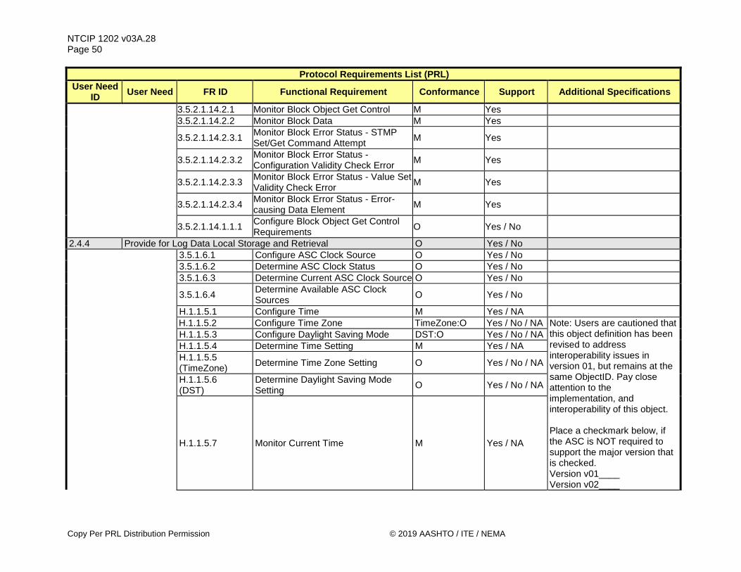
NTCIP 1202 v03A.28 Page 50
Copy Per PRL Distribution Permission © 2019 AASHTO / ITE / NEMA
Protocol Requirements List (PRL) User Need
ID User Need FR ID Functional Requirement Conformance Support Additional Specifications
3.5.2.1.14.2.1 Monitor Block Object Get Control M Yes 3.5.2.1.14.2.2 Monitor Block Data M Yes
3.5.2.1.14.2.3.1 Monitor Block Error Status - STMP Set/Get Command Attempt M Yes
3.5.2.1.14.2.3.2 Monitor Block Error Status - Configuration Validity Check Error M Yes
3.5.2.1.14.2.3.3 Monitor Block Error Status - Value Set Validity Check Error M Yes
3.5.2.1.14.2.3.4 Monitor Block Error Status - Error-causing Data Element M Yes
3.5.2.1.14.1.1.1 Configure Block Object Get Control Requirements O Yes / No
2.4.4 Provide for Log Data Local Storage and Retrieval O Yes / No 3.5.1.6.1 Configure ASC Clock Source O Yes / No 3.5.1.6.2 Determine ASC Clock Status O Yes / No 3.5.1.6.3 Determine Current ASC Clock Source O Yes / No
3.5.1.6.4 Determine Available ASC Clock Sources O Yes / No
H.1.1.5.1 Configure Time M Yes / NA H.1.1.5.2 Configure Time Zone TimeZone:O Yes / No / NA Note: Users are cautioned that
this object definition has been revised to address interoperability issues in version 01, but remains at the same ObjectID. Pay close attention to the implementation, and interoperability of this object. Place a checkmark below, if the ASC is NOT required to support the major version that is checked. Version v01____ Version v02____
H.1.1.5.3 Configure Daylight Saving Mode DST:O Yes / No / NA H.1.1.5.4 Determine Time Setting M Yes / NA
H.1.1.5.5 (TimeZone) Determine Time Zone Setting O Yes / No / NA
H.1.1.5.6 (DST)
Determine Daylight Saving Mode Setting O Yes / No / NA
H.1.1.5.7 Monitor Current Time M Yes / NA

NTCIP 1202 v03A.28 Page 51
© 2019 AASHTO / ITE / NEMA Copy Per PRL Distribution Permission
Protocol Requirements List (PRL) User Need
ID User Need FR ID Functional Requirement Conformance Support Additional Specifications
H.1.3.1.1 Retrieve Current Configuration of Logging Service M Yes / NA
H.1.3.1.2 Configure Event Logging Service M Yes / NA H.1.3.1.3 Retrieve Event Logged Data M Yes / NA
H.1.3.1.4 Configure Clearing of Event Class Log M Yes / NA
H.1.3.1.5 Determine Capabilities of Event Logging Service M Yes / NA
H.1.3.1.6 Determine Number of Logged Events per Event Class M Yes / NA
H.1.3.1.7 Support a Number of Events to Store in Log M Yes / NA
The ASC shall be capable of storing at least ____ events in the event log file (up to 65535).
H.1.3.1.8 Configure Clearing of Global Log O Yes / No / NA
H.1.3.1.9 Determine Total Number of Logged Events O Yes / No / NA
H.1.3.1.10 Determine Number of Events within a Class M Yes / NA
H.1.3.1.11 Determine Event Logging Resolution M Yes / NA H.1.3.1.12 Clear Event Configuration M Yes / NA H.1.3.1.13 Clear Event Classes M Yes / NA H.1.3.1.14 Clear Event Class Log M Yes / NA
H.1.3.1.15 Retrieve Non-Sequential Clock Changes O Yes / No / NA
H.1.3.2.1 Record and Timestamp Events M Yes / NA
H.1.3.2.2 Support a Number of Event Classes M Yes / NA The ASC shall support at least ____ event classes.
H.1.3.2.3 Support a Number of Events to Log M Yes / NA The ASC shall be able to log at least ____ events.
H.1.3.2.4.1 Support On-Change Events M Yes / NA H.1.3.2.4.2 Support Greater Than Events M Yes / NA H.1.3.2.4.3 Support Less Than Events M Yes / NA H.1.3.2.4.4 Support Hysteresis Events M Yes / NA H.1.3.2.4.5 Support Periodic Events M Yes / NA H.1.3.2.4.6 Support Bit Flag Events M Yes / NA

NTCIP 1202 v03A.28 Page 52
Copy Per PRL Distribution Permission © 2019 AASHTO / ITE / NEMA
Protocol Requirements List (PRL) User Need
ID User Need FR ID Functional Requirement Conformance Support Additional Specifications
H.1.3.2.4.7 Support Event Monitoring on Any Data M Yes / NA
3.6.1 Response Time for Requests M Yes / NA
The Response Time for all requests shall be ___ milliseconds (5-500: Default=25).
2.4.5 Provide for Database Management M Yes H.1.2.2.1 Monitor Database Operation M Yes H.1.2.2.2 Monitor Database Operation Status M Yes
H.1.2.2.3 Monitor Database Operation Error Status M Yes
H.1.4.2.1 Control Database Access M Yes
H.1.4.2.2 Perform Database Consistency Check M Yes
H.1.4.2.3 Enforce Consistency Check Parameters M Yes
2.4.6 (Traps) Condition-based Exception Reporting O Yes / No
3.6.2 Condition-based Maximum Transmission Start Time M Yes
The Maximum Transmission Start Time for all reports shall be ___ milliseconds (Default=10000).
H.1.1.10.1 Enable/Disable Exception Reporting M Yes
H.1.1.10.2.1 Configure a Monitored (Watch) Object M Yes
H.1.1.10.2.2 (Watch)
Configure a Monitored Group of Objects (Watch Block) M Yes
H.1.1.10.3.1 Configure a Report Object M Yes
H.1.1.10.3.2 (Report)
Configure a Report Group of Objects (Block) M Yes
H.1.1.10.4 Configure Exception Reporting Destination M Yes
H.1.1.10.5 Configure Exception Reporting Community M Yes
H.1.1.10.6.1 (TrapAck)
Configure Exception Reporting Acknowledgement O.2 (1..*) Yes / No

NTCIP 1202 v03A.28 Page 53
© 2019 AASHTO / ITE / NEMA Copy Per PRL Distribution Permission
Protocol Requirements List (PRL) User Need
ID User Need FR ID Functional Requirement Conformance Support Additional Specifications
H.1.1.10.6.2 Configure Exception Reporting Aggregation O.2 (1..*) Yes / No
H.1.1.10.6.3 (TrapQueue)
Configure Exception Reporting Queue O.2 (1..*) Yes / No
H.1.1.10.6.4 Configure Exception Reporting (Forced) O.2 (1..*) Yes / No
H.1.1.10.6.5 Configure Exception Reporting Communications M Yes
H.1.1.10.6.6 (AntiStream)
Configure Exception Reporting - Maximum Rate O Yes / No
H.1.1.10.7 Determine Watch Block Capabilities Watch:M Yes / NA H.1.1.10.8 Determine Report Block Capabilities Report:M Yes / NA
H.1.1.10.9 Determine Exception Reporting Trap Channel Capabilities M Yes
H.1.1.10.10 Determine Exception Reporting Aggregation Capabilities M Yes
H.1.1.10.11 Determine Event Reporting Latency M Yes H.1.1.10.12 Monitor Communications Link State M Yes
H.1.1.10.13.1 Monitor Exception Based Communications Link Error M Yes
H.1.1.10.13.2 Monitor Exception Based Maximum Rate Exceeded AntiStream:M Yes / NA
H.1.1.10.13.3 Monitor Exception Based Queue Full Error TrapQueue:M Yes / NA
H.1.1.10.14 Monitor Exception Based Transmissions M Yes
H.1.1.10.15 Monitor Number of Lost Queued Exception Based Reports TrapQueue:M Yes / NA
H.1.1.10.16 Monitor Number of Exception Based Events M Yes
H.1.1.10.17 Monitor Exception Based Data M Yes H.1.1.10.18 Clear Event Class O Yes / No H.1.1.10.19 Clear Event Configuration O Yes / No H.1.1.10.20 Clear Event Log Table O Yes / No H.1.1.10.21 Clear Report Objects O Yes / No

NTCIP 1202 v03A.28 Page 54
Copy Per PRL Distribution Permission © 2019 AASHTO / ITE / NEMA
Protocol Requirements List (PRL) User Need
ID User Need FR ID Functional Requirement Conformance Support Additional Specifications
H.1.1.10.22 Clear Report Blocks O Yes / No H.1.1.10.23 Clear Watch Objects O Yes / No H.1.1.10.24 Clear Watch Blocks O Yes / No
H.1.1.10.25 Clear Exception Based Reporting Tables O Yes / No
H.1.1.10.26 Reset a Communications Link TrapAck:O Yes / No / NA H.1.5.1 Atomic Operations M Yes 2.5 Features 2.5.1 Manage the ASC Configuration M Yes 2.5.1.1 Retrieve Device Identity M Yes
3.5.1.1.1 Configure ASC Location O Yes / No Only needed if no external GNSS device is attached to the ASC
3.5.1.1.2 Configure ASC Location - Antenna Offset O Yes / No
Only needed if an external GNSS device is attached to the ASC
H.1.1.1 Determine Device Component Information M Yes
H.1.1.2.1 Determine Unique Deployment Configuration Identifier M Yes
H.1.1.2.2 Determine Configuration Identifier Parameter Content O Yes / No
H.1.1.3 Determine Supported Standards M Yes Note: was optional in NTCIP 1202 v02
H.1.1.4 Manage Unique System Name O Yes / No 2.5.1.2 Manage Communications O Yes / No
3.5.1.2.1.1 Enable/Disable Communications Port M Yes
The ASC shall not be allowed to enable/disable the following ports numbers: ________________________ ________________________
3.5.1.2.1.2 Configure ASC Ethernet Ports O Yes / No The ASC shall not be allowed to configure the following ports: ________________________

NTCIP 1202 v03A.28 Page 55
© 2019 AASHTO / ITE / NEMA Copy Per PRL Distribution Permission
Protocol Requirements List (PRL) User Need
ID User Need FR ID Functional Requirement Conformance Support Additional Specifications
3.5.1.2.1.3 Configure ASC Asynchronous Serial Ports O Yes / No
The ASC shall not be allowed to configure the following ports: ________________________
3.5.1.2.1.4 Configure ASC Synchronous Serial Ports O Yes / No
The ASC shall not be allowed to configure the following ports: ________________________
3.5.1.2.1.5 Configure ASC Communications Protocol - Serial Ports O Yes / No
The ASC shall not be allowed to configure the following ports: ________________________
3.5.1.2.2.1 Determine Number of ASC Communications Ports M Yes
3.5.1.2.3.1 Monitor Response Timeout - Ethernet O Yes / No 3.5.1.2.3.2 Monitor Response Timeout - Serial O Yes / No 3.5.1.2.3.3 Monitor Data Link Errors - Ethernet O Yes / No 3.5.1.2.3.4 Monitor Data Link Errors - Serial O Yes / No
3.5.1.2.3.5 Monitor Polling Timeout - Port 1 TS1:O, TS2-2:O, TS2-1:O Yes / No / NA
3.5.1.2.3.6 Monitor Polling Timeout - Serial Bus ITS:O Yes / No / NA
3.5.1.2.4.1 Set Communications Port to Loopback Mode O Yes / No
3.5.1.2.4.2 Set Communications Port to Echo Mode O Yes / No
2.5.1.3 Manage Cabinet Environment O Yes / No 3.5.1.3.1 Monitor Cabinet Door Status M Yes 3.5.1.3.2 Monitor Cabinet Fan Status O Yes / No 3.5.1.3.3 Monitor Cabinet Heater Status O Yes / No 3.5.1.3.4 Monitor Cabinet Float Switch Status O Yes / No
3.5.1.3.5 (Temp) Monitor ASC Temperature O Yes / No
3.5.1.3.6 (Humidity) Monitor ASC Humidity O Yes / No
3.5.1.3.7 Configure ASC Temperature Threshold Temp:O Yes / No / NA
3.5.1.3.8 Configure ASC Humidity Thresholds Humidity:O Yes / No / NA 3.5.1.3.9 Configure ATC Cabinet Device LEDs O Yes / No

NTCIP 1202 v03A.28 Page 56
Copy Per PRL Distribution Permission © 2019 AASHTO / ITE / NEMA
Protocol Requirements List (PRL) User Need
ID User Need FR ID Functional Requirement Conformance Support Additional Specifications
2.5.1.4 (Power) Monitor Power O Yes / No
3.5.1.4.1 Determine Power Source M Yes 3.5.1.4.2 Monitor AC Power Status O Yes / No
3.5.1.4.3 (UPS) Monitor UPS Battery Charge O Yes / No
3.5.1.4.4 Monitor UPS Battery Voltage UPS:O Yes / No / NA 3.5.1.4.5 Monitor UPS Battery Current UPSO Yes / No / NA 2.5.1.5 (Perform) Retrieve Operational Performance Data O Yes / No
3.5.1.5.1.1 Enable/Disable Collection of Operational Performance Data M Yes
3.5.1.5.1.2 Start Collection of Operational Performance Data on Specific Date/Time
O Yes / No
3.5.1.5.1.3 End Collection of Operational Performance Data on Specific Date/Time
O Yes / No
3.5.1.5.1.4 Configure Collection of Operational Performance Data O Yes / No
3.5.1.5.2.1 Determine Collection of Operational Performance Data M Yes
The ASC shall allow the recording of at least ____ days' worth of data for each event code at a recording interval of 1/10 seconds (maximum 7 days).
3.5.1.5.2.2 Determine Operational Performance Data Collection Capabilities M Yes
3.5.1.5.3.1 Monitor Operational Performance Data O Yes / No
3.5.1.5.3.2 Retrieve Operational Performance Data O Yes / No
3.5.1.5.3.3 Retrieve Operational Performance Data - Time Range O Yes / No
3.5.1.5.3.4 Retrieve Operational Performance Data - Event Code O Yes / No

NTCIP 1202 v03A.28 Page 57
© 2019 AASHTO / ITE / NEMA Copy Per PRL Distribution Permission
Protocol Requirements List (PRL) User Need
ID User Need FR ID Functional Requirement Conformance Support Additional Specifications
3.5.1.5.4.1 Clear Operational Performance Data - All O Yes / No
3.5.1.5.4.2 Clear Operational Performance Data - Time Range O Yes / No
3.5.1.5.4.3 Clear Operational Performance Data - Event Code O Yes / No
3.5.1.5.4.4 Clear Operational Performance Data - Event Class O Yes / No
3.5.1.5.4.5 Clear Operational Performance Data - Configuration O Yes / No
2.5.1.6 Manage Auxiliary External Inputs/Outputs O Yes / No H.1.1.6.1 Determine External Port Information M Yes H.1.1.6.2 Configure Port Information M Yes
H.1.1.6.3 Required Number of Auxiliary Ports O Yes / No
The ASC shall support at least ____ analog Auxiliary Ports. The ASC shall support at least ____ digital Auxiliary Ports.
H.1.2.1 Monitor Status of External Device O Yes / No H.1.4.1 Control External Device O Yes / No 2.5.1.7 Manage Database M Yes
3.5.2.1.1.6 Configure Parameters for Creation of an Alternate Device Configuration Identifier
O Yes / No
H.1.1.2.1 Determine Unique Deployment Configuration Identifier M Yes
H.1.1.2.2 Determine Configuration Identifier Parameter Content O Yes / No
2.5.2 Manage Signal Operations M Yes 2.5.2.1 Manage Signal Configuration M Yes 2.5.2.1.1 Manage Controller Startup Functions M Yes
3.5.2.1.1.1.1 Configure Startup All-Red Flash Mode O Yes / No
3.5.2.1.1.1.2 Configure Startup Flash Time M Yes
3.5.2.1.1.1.3 Enable/Disable Automatic Pedestrian Clearance Setting M Yes
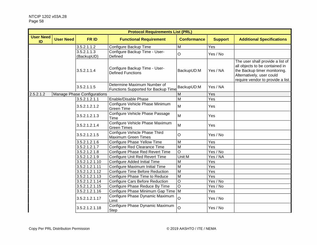
NTCIP 1202 v03A.28 Page 58
Copy Per PRL Distribution Permission © 2019 AASHTO / ITE / NEMA
Protocol Requirements List (PRL) User Need
ID User Need FR ID Functional Requirement Conformance Support Additional Specifications
3.5.2.1.1.2 Configure Backup Time M Yes
3.5.2.1.1.3 (BackupUD)
Configure Backup Time - User-Defined O Yes / No
3.5.2.1.1.4 Configure Backup Time - User-Defined Functions BackupUD:M Yes / NA
The user shall provide a list of all objects to be contained in the Backup timer monitoring. Alternatively, user could require vendor to provide a list.
3.5.2.1.1.5 Determine Maximum Number of Functions Supported for Backup Time BackupUD:M Yes / NA
2.5.2.1.2 Manage Phase Configurations M Yes 3.5.2.1.2.1.1 Enable/Disable Phase M Yes
3.5.2.1.2.1.2 Configure Vehicle Phase Minimum Green Time M Yes
3.5.2.1.2.1.3 Configure Vehicle Phase Passage Time M Yes
3.5.2.1.2.1.4 Configure Vehicle Phase Maximum Green Times M Yes
3.5.2.1.2.1.5 Configure Vehicle Phase Third Maximum Green Times O Yes / No
3.5.2.1.2.1.6 Configure Phase Yellow Time M Yes 3.5.2.1.2.1.7 Configure Red Clearance Time M Yes 3.5.2.1.2.1.8 Configure Phase Red Revert Time O Yes / No 3.5.2.1.2.1.9 Configure Unit Red Revert Time Unit:M Yes / NA 3.5.2.1.2.1.10 Configure Added Initial Time M Yes 3.5.2.1.2.1.11 Configure Maximum Initial Time M Yes 3.5.2.1.2.1.12 Configure Time Before Reduction M Yes 3.5.2.1.2.1.13 Configure Phase Time to Reduce M Yes 3.5.2.1.2.1.14 Configure Cars Before Reduction O Yes / No 3.5.2.1.2.1.15 Configure Phase Reduce By Time O Yes / No 3.5.2.1.2.1.16 Configure Phase Minimum Gap Time M Yes
3.5.2.1.2.1.17 Configure Phase Dynamic Maximum Limit O Yes / No
3.5.2.1.2.1.18 Configure Phase Dynamic Maximum Step O Yes / No

NTCIP 1202 v03A.28 Page 59
© 2019 AASHTO / ITE / NEMA Copy Per PRL Distribution Permission
Protocol Requirements List (PRL) User Need
ID User Need FR ID Functional Requirement Conformance Support Additional Specifications
3.5.2.1.2.1.19.1 Configure Phase Startup - Initialize in a Red State O.3 (1..*) Yes / No
3.5.2.1.2.1.19.2 Configure Phase Startup - Initialize at Beginning of Min Green and Walk O.3 (1..*) Yes / No
3.5.2.1.2.1.19.3 Configure Phase Startup - Initialize at Beginning of Min Green O.3 (1..*) Yes / No
3.5.2.1.2.1.19.4 Configure Phase Startup - Initialize at Beginning of Yellow O.3 (1..*) Yes / No
3.5.2.1.2.1.19.5 Configure Phase Startup - Initialize at Beginning of Red Clearance O.3 (1..*) Yes / No
3.5.2.1.2.1.20 Configure Automatic Flash Entry Phase O Yes / No
3.5.2.1.2.1.21 Configure Automatic Flash Exit Phase O Yes / No
3.5.2.1.2.1.22 Configure Call to Non-Actuated 1 O Yes / No 3.5.2.1.2.1.23 Configure Call to Non-Actuated 2 O Yes / No
3.5.2.1.2.1.24 Configure Non-Lock Detector Memory O Yes / No
3.5.2.1.2.1.25 Configure Minimum Vehicle Recall O Yes / No 3.5.2.1.2.1.26 Configure Maximum Vehicle Recall O Yes / No 3.5.2.1.2.1.27 Configure Soft Vehicle Recall O Yes / No 3.5.2.1.2.1.28 Configure Dual Phase Entry O Yes / No 3.5.2.1.2.1.29 Configure Simultaneous Gap Disable O Yes / No 3.5.2.1.2.1.30 Configure Guaranteed Passage O Yes / No 3.5.2.1.2.1.31 Configure Actuated Rest-in-Walk O Yes / No 3.5.2.1.2.1.32 Configure Conditional Service Enable O Yes / No 3.5.2.1.2.1.33 Configure Added Initial Calculation O Yes / No 3.5.2.1.2.1.34 Configure Phase-to-Ring Association M Yes 3.5.2.1.2.1.35 Configure Phase Concurrency M Yes
3.5.2.1.2.1.36 Configure Yellow Change Time Before End of Ped Clearance O Yes / No
3.5.2.1.2.1.37 Enable/Disable Ped-only Phase O Yes / No 3.5.2.1.2.1.38 Configure Pedestrian Green Time M Yes 3.5.2.1.2.1.39 Configure Pedestrian Clearance Time M Yes

NTCIP 1202 v03A.28 Page 60
Copy Per PRL Distribution Permission © 2019 AASHTO / ITE / NEMA
Protocol Requirements List (PRL) User Need
ID User Need FR ID Functional Requirement Conformance Support Additional Specifications
3.5.2.1.2.1.40 Configure Ped Phase Walk Recycle Time M Yes
3.5.2.1.2.1.41 Configure Ped Phase Don't Walk Revert Time M Yes
3.5.2.1.2.1.42 Configure Non-Lock Ped Detector Memory M Yes
3.5.2.1.2.1.43 Configure Pedestrian Recall M Yes
3.5.2.1.2.1.44 Configure Alternate Pedestrian Clearance Time O Yes / No
3.5.2.1.2.1.45 Configure Alternate Pedestrian Walk Time O Yes / No
3.5.2.1.2.1.46 Configure Vehicle Phase Walk Offset Time O Yes / No
3.5.2.1.2.1.47 (AdvGrWarn)
Configure Advanced Green Warning - Associated Vehicle Phase O Yes / No
3.5.2.1.2.1.48 Configure Advanced Green Warning - Start Delay Time AdvGrWarn:M Yes / NA
3.5.2.1.2.1.49 (AdvRdWarn)
Configure Advanced Red Warning - Associated Vehicle Phase O Yes / No
3.5.2.1.2.1.50 Configure Red Indication Advanced Warning - Start Delay Time AdvRdWarn:M Yes / NA
3.5.2.1.2.1.51 Configure Flashing Yellow Arrow Associated Vehicle Phase O Yes / No
3.5.2.1.2.1.52 Configure Flashing Red Arrow Associated Vehicle Phase O Yes / No
3.5.2.1.2.1.53 (Bicycle)
Configure Bicycle Phase Minimum Green Time O Yes / No
3.5.2.1.2.1.54 Configure Bicycle Phase Yellow Time Bicycle:M Yes / NA
3.5.2.1.2.1.55 Configure Bicycle Phase Red Clearance Time Bicycle:M Yes / NA
3.5.2.1.2.1.56 Configure Bicycle Phase Red Revert Time Bicycle:O Yes / No / NA
3.5.2.1.2.1.57 Enable/Disable Bicycle Phase Bicycle:O Yes / No / NA
3.5.2.1.2.1.58 Configure Non-Lock Bicycle Detector Memory Bicycle:O Yes / No / NA

NTCIP 1202 v03A.28 Page 61
© 2019 AASHTO / ITE / NEMA Copy Per PRL Distribution Permission
Protocol Requirements List (PRL) User Need
ID User Need FR ID Functional Requirement Conformance Support Additional Specifications
3.5.2.1.2.1.59 Configure Bicycle Phase Recall Bicycle:O Yes / No / NA 3.5.2.1.2.1.60 Configure Soft Bicycle Phase Recall Bicycle:O Yes / No / NA
3.5.2.1.2.1.61 Configure Bicycle Phase-to-Ring Association Bicycle:M Yes / NA
3.5.2.1.2.1.62 Configure Bicycle Phase Concurrency Bicycle:M Yes / NA
3.5.2.1.2.1.63 (Transit)
Configure Transit Phase Minimum Green Time O Yes / No
3.5.2.1.2.1.64 Configure Transit Phase Maximum Green Time Transit:M Yes / NA
3.5.2.1.2.1.65 Configure Transit Phase Third Maximum Green Time Transit:O Yes / No / NA
3.5.2.1.2.1.66 Configure Transit Phase Yellow Time Transit:M Yes / NA
3.5.2.1.2.1.67 Configure Transit Phase Red Clearance Time Transit:M Yes / NA
3.5.2.1.2.1.68 Configure Transit Phase Red Revert Time Transit:O Yes / No / NA
3.5.2.1.2.1.69 Configure Transit Phase Added Initial Time Transit:M Yes / NA
3.5.2.1.2.1.70 Configure Transit Phase Maximum Initial Time Transit:M Yes / NA
3.5.2.1.2.1.71 Enable/Disable Transit Phase Transit:M Yes / NA
3.5.2.1.2.1.72 Configure Non-Lock Transit Detector Memory Transit:O Yes / No / NA
3.5.2.1.2.1.73 Configure Transit Phase Recall Transit:O Yes / No / NA 3.5.2.1.2.1.74 Configure Soft Transit Phase Recall Transit:O Yes / No / NA 3.5.2.1.2.1.75 Configure Dual Transit Phase Entry Transit:O Yes / No / NA
3.5.2.1.2.1.76 Configure Transit Phase-to-Ring Association Transit:M Yes / NA
3.5.2.1.2.1.77 Configure Transit Phase Concurrency Transit:M Yes / NA 3.5.2.1.2.1.78 Enable/Disable Vehicle Phase Omit PhsCtrl:M Yes / NA
3.5.2.1.2.1.79 Enable/Disable Vehicle Phase Omit during Transition O Yes / No
3.5.2.1.2.1.80 Enable/Disable Ped-only Phase Omit PhsCtrl:M Yes / NA

NTCIP 1202 v03A.28 Page 62
Copy Per PRL Distribution Permission © 2019 AASHTO / ITE / NEMA
Protocol Requirements List (PRL) User Need
ID User Need FR ID Functional Requirement Conformance Support Additional Specifications
3.5.2.1.2.1.81 Enable/Disable Ped-only Phase Omit during Transition O Yes / No
3.5.2.1.2.1.82 Enable/Disable Bicycle-only Phase Omit
Bicycle, PhsCtrl:M Yes / NA
3.5.2.1.2.1.83 Enable/Disable Bicycle-only Phase Omit during Transition Bicycle:O Yes / No / NA
3.5.2.1.2.1.84 Enable/Disable Transit Phase Omit Transit, PhsCtrl:M Yes / NA
3.5.2.1.2.1.85 Enable/Disable Transit Phase Omit during Transition Transit:O Yes / No / NA
3.5.2.1.2.1.86 Configure Alternate Minimum Vehicle Green Time during Transition O Yes / No
3.5.2.1.2.1.87 Configure Alternate Minimum Pedestrian Walk Time during Transition
O Yes / No
3.5.2.1.2.1.88 Configure Alternate Minimum Bicycle Green Time during Transition Bicycle:O Yes / No / NA
3.5.2.1.2.1.89 Configure Alternate Minimum Transit Green Time during Transition Transit:O Yes / No / NA
3.5.2.1.2.1.90.1 Configure Phase-level Force Mode for Coordination - Floating Coord:O.4 (1..*) Yes / No / NA
3.5.2.1.2.1.90.2 Configure Phase-level Force Mode for Coordination - Fixed Coord:O.4 (1..*) Yes / No / NA
3.5.2.1.2.2.1 Determine Maximum Number of Phases M Yes The ASC shall support at least
____ phases. 2.5.2.1.3 (Coord) Manage Coordination Configurations O Yes / No
3.5.2.1.3.1.1 Configure Operational Mode for Coordination - Automatic O.5 (1..*) Yes / No
3.5.2.1.3.1.2 Configure Operational Mode for Coordination - Manual Pattern O.5 (1..*) Yes / No
3.5.2.1.3.1.3 Configure Operational Mode for Coordination - Manual Free O.5 (1..*) Yes / No
3.5.2.1.3.1.4 Configure Operational Mode for Coordination - Manual Flash O.5 (1..*) Yes / No

NTCIP 1202 v03A.28 Page 63
© 2019 AASHTO / ITE / NEMA Copy Per PRL Distribution Permission
Protocol Requirements List (PRL) User Need
ID User Need FR ID Functional Requirement Conformance Support Additional Specifications
3.5.2.1.3.2.1 Configure Correction Mode for Coordination - Dwell O.6 (1..*) Yes / No
3.5.2.1.3.2.2 Configure Correction Mode for Coordination - Shortway O.6 (1..*) Yes / No
3.5.2.1.3.2.3 Configure Correction Mode for Coordination - AddOnly O.6 (1..*) Yes / No
3.5.2.1.3.2.4 Configure Correction Mode for Coordination - SubtractOnly O.6 (1..*) Yes / No
3.5.2.1.3.3.1 Configure Correction Mode for Coordination - Maximum 1 O.7 (1..*) Yes / No
3.5.2.1.3.3.2 Configure Correction Mode for Coordination - Maximum 2 O.7 (1..*) Yes / No
3.5.2.1.3.3.3 Configure Correction Mode for Coordination - Maximum Inhibit O.7 (1..*) Yes / No
3.5.2.1.3.3.4 Configure Correction Mode for Coordination - Maximum 3 O.7 (1..*) Yes / No
3.5.2.1.3.4.1 Configure Unit-level Force Mode for Coordination - Floating O.8 (1..*) Yes / No
3.5.2.1.3.4.2 Configure Unit-level Force Mode for Coordination - Fixed O.8 (1..*) Yes / No
3.5.2.1.3.5.1 Configure Unit Coordination Point - First Phase Green Begin
O.9 (1..*) Yes / No
3.5.2.1.3.5.2 Configure Unit Coordination Point - Last Phase Green Begin
O.9 (1..*) Yes / No
3.5.2.1.3.5.3 Configure Unit Coordination Point - First Phase Green End
O.9 (1..*) Yes / No
3.5.2.1.3.5.4 Configure Unit Coordination Point - Last Phase Green End
O.9 (1..*) Yes / No
3.5.2.1.3.5.5 Configure Unit Coordination Point - First Phase Yellow End
O.9 (1..*) Yes / No
3.5.2.1.3.5.6 Configure Unit Coordination Point - Last Phase Yellow End
O.9 (1..*) Yes / No
3.5.2.1.3.6.1 Configure Coordination Point - First Phase Green Begin
O.10 (1..*) Yes / No
3.5.2.1.3.6.2 Configure Coordination Point - Last Phase Green Begin
O.10 (1..*) Yes / No
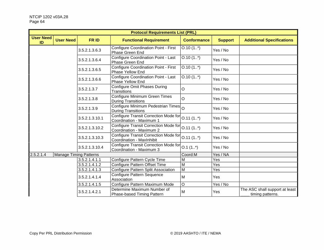
NTCIP 1202 v03A.28 Page 64
Copy Per PRL Distribution Permission © 2019 AASHTO / ITE / NEMA
Protocol Requirements List (PRL) User Need
ID User Need FR ID Functional Requirement Conformance Support Additional Specifications
3.5.2.1.3.6.3 Configure Coordination Point - First Phase Green End
O.10 (1..*) Yes / No
3.5.2.1.3.6.4 Configure Coordination Point - Last Phase Green End
O.10 (1..*) Yes / No
3.5.2.1.3.6.5 Configure Coordination Point - First Phase Yellow End
O.10 (1..*) Yes / No
3.5.2.1.3.6.6 Configure Coordination Point - Last Phase Yellow End
O.10 (1..*) Yes / No
3.5.2.1.3.7 Configure Omit Phases During Transitions O Yes / No
3.5.2.1.3.8 Configure Minimum Green Times During Transitions O Yes / No
3.5.2.1.3.9 Configure Minimum Pedestrian Times During Transitions O Yes / No
3.5.2.1.3.10.1 Configure Transit Correction Mode for Coordination - Maximum 1 O.11 (1..*) Yes / No
3.5.2.1.3.10.2 Configure Transit Correction Mode for Coordination - Maximum 2 O.11 (1..*) Yes / No
3.5.2.1.3.10.3 Configure Transit Correction Mode for Coordination - MaxInhibit O.11 (1..*) Yes / No
3.5.2.1.3.10.4 Configure Transit Correction Mode for Coordination - Maximum 3 O.1 (1..*) Yes / No
2.5.2.1.4 Manage Timing Patterns Coord:M Yes / NA 3.5.2.1.4.1.1 Configure Pattern Cycle Time M Yes 3.5.2.1.4.1.2 Configure Pattern Offset Time M Yes 3.5.2.1.4.1.3 Configure Pattern Split Association M Yes
3.5.2.1.4.1.4 Configure Pattern Sequence Association M Yes
3.5.2.1.4.1.5 Configure Pattern Maximum Mode O Yes / No
3.5.2.1.4.2.1 Determine Maximum Number of Phase-based Timing Pattern M Yes The ASC shall support at least
____ timing patterns.

NTCIP 1202 v03A.28 Page 65
© 2019 AASHTO / ITE / NEMA Copy Per PRL Distribution Permission
Protocol Requirements List (PRL) User Need
ID User Need FR ID Functional Requirement Conformance Support Additional Specifications
3.5.2.1.4.2.2 Determine Phase-based Timing Pattern Type M Yes
The ASC shall support one of the following types of signal patterns (Select one only): ____ Each pattern is unique ____ Each pattern consists of a plan with 3 different offsets ____ Each pattern consists of a plan with 5 different offsets
2.5.2.1.5 Manage Splits Configurations O Yes / No 3.5.2.1.5.1.1 Configure Phase Split Time M Yes 3.5.2.1.5.1.2.1 Configure Phase Split Mode - None O.12 (1..*) Yes / No
3.5.2.1.5.1.2.2 Configure Phase Split Mode - Minimum Vehicle Recall O.12 (1..*) Yes / No
3.5.2.1.5.1.2.3 Configure Phase Split Mode - Maximum Vehicle Recall O.12 (1..*) Yes / No
3.5.2.1.5.1.2.4 Configure Phase Split Mode - Pedestrian Recall O.12 (1..*) Yes / No
3.5.2.1.5.1.2.5 Configure Phase Split Mode - Maximum Vehicle and Pedestrian Recall
O.12 (1..*) Yes / No
3.5.2.1.5.1.2.6 Configure Phase Split Mode - Phase Omit O.12 (1..*) Yes / No
3.5.2.1.5.1.2.7 Configure Phase Split Mode - Bicycle Recall O.12 (1..*) Yes / No
3.5.2.1.5.1.2.8 Configure Phase Split Mode - Transit Recall O.12 (1..*) Yes / No
3.5.2.1.5.1.2.9 Configure Phase Split Mode - Non-Actuated O.12 (1..*) Yes / No
3.5.2.1.5.1.3 Configure Split Coordination Phase M Yes 3.5.2.1.5.1.4 Configure Pre-timed Split O Yes / No
3.5.2.1.5.2.1 Determine Maximum Number of Phase Splits M Yes The ASC shall support at least
____ splits 2.5.2.1.6 (Ring) Manage Ring Configurations O Yes / No
3.5.2.1.6.1.1 Configure Sequence Data M Yes

NTCIP 1202 v03A.28 Page 66
Copy Per PRL Distribution Permission © 2019 AASHTO / ITE / NEMA
Protocol Requirements List (PRL) User Need
ID User Need FR ID Functional Requirement Conformance Support Additional Specifications
3.5.2.1.6.2.1 Determine Maximum Number of Rings M Yes The ASC shall support at least
____ rings
3.5.2.1.6.2.2 Determine Maximum Number of Sequences M Yes The ASC shall support at least
____ sequences 2.5.2.1.7 (Channel) Manage Channel Configurations O Yes / No
3.5.2.1.7.1.1 Configure Channel Control Source M Yes
3.5.2.1.7.1.2.1 Configure Channel Control Type - Vehicle Phase O.13 (1..*) Yes / No
3.5.2.1.7.1.2.2 Configure Channel Control Type - Vehicle Overlap Phase O.13 (1..*) Yes / No
3.5.2.1.7.1.2.3 Configure Channel Control Type - Pedestrian Phase O.13 (1..*) Yes / No
3.5.2.1.7.1.2.4 Configure Channel Control Type - Pedestrian Overlap Phase O.13 (1..*) Yes / No
3.5.2.1.7.1.2.5 Configure Channel Control Type - Bicycle Phase O.13 (1..*) Yes / No
3.5.2.1.7.1.2.6 Configure Channel Control Type - Bicycle Overlap Phase O.13 (1..*) Yes / No
3.5.2.1.7.1.2.7 Configure Channel Control Type - Transit Phase O.13 (1..*) Yes / No
3.5.2.1.7.1.2.8 Configure Channel Control Type - Transit Overlap Phase O.13 (1..*) Yes / No
3.5.2.1.7.1.2.9 Configure Channel Control Type - Queue Jump Phase O.13 (1..*) Yes / No
3.5.2.1.7.1.3.1 Enable/Disable Channel Flash - Yellow O.14 (1..*) Yes / No
3.5.2.1.7.1.3.2 Enable/Disable Channel Flash - Red O.14 (1..*) Yes / No
3.5.2.1.7.1.3.3 Enable/Disable Channel Flash - Alternate Half Hertz O.14 (1..*) Yes / No
3.5.2.1.7.1.4.1 Enable/Disable Channel Dim - Green Dimming:O Yes / No / NA 3.5.2.1.7.1.4.2 Enable/Disable Channel Dim - Yellow Dimming:O Yes / No / NA 3.5.2.1.7.1.4.3 Enable/Disable Channel Dim - Red Dimming:O Yes / No / NA
3.5.2.1.7.1.4.4 Enable/Disable Channel Dim - Alternate Half Hertz
Dimming:O Yes / No / NA

NTCIP 1202 v03A.28 Page 67
© 2019 AASHTO / ITE / NEMA Copy Per PRL Distribution Permission
Protocol Requirements List (PRL) User Need
ID User Need FR ID Functional Requirement Conformance Support Additional Specifications
3.5.2.1.7.2.1 Determine Maximum Number of Channels M Yes
The ASC shall support at least ____ channels (See appropriate hardware specification such as NEMA TS 2 to determine maximum number of supported channels)
2.5.2.1.8 (Overlap) Manage Overlap Configurations O Yes / No
3.5.2.1.8.1.1.1 Configure Overlap Type - Vehicle Normal O.15 (1..*) Yes / No
3.5.2.1.8.1.1.2 Configure Overlap Type - Vehicle Minus Green and Yellow O.15 (1..*) Yes / No
3.5.2.1.8.1.1.3 Configure Overlap Type - Pedestrian Normal O.15 (1..*) Yes / No
3.5.2.1.8.1.1.4 Configure Overlap Type - Bicycle Normal O.15 (1..*) Yes / No
3.5.2.1.8.1.1.5 Configure Overlap Type - Transit Normal O.15 (1..*) Yes / No
3.5.2.1.8.1.1.6 Configure Overlap Type - Flashing Yellow Arrow - 3 Section Head O.15 (1..*) Yes / No
3.5.2.1.8.1.1.7 Configure Overlap Type - Flashing Yellow Arrow - 4 Section Head O.15 (1..*) Yes / No
3.5.2.1.8.1.1.8 Configure Overlap Type - Flashing Yellow Arrow for Pedestrians O.15 (1..*) Yes / No
3.5.2.1.8.1.1.9 Configure Overlap Type - Flashing Red Arrow - 3 Section Head O.15 (1..*) Yes / No
3.5.2.1.8.1.1.10 Configure Overlap Type - Flashing Red Arrow - 4 Section Head O.15 (1..*) Yes / No
3.5.2.1.8.1.1.11 Configure Overlap Type - Transit Specific Signal Head O.15 (1..*) Yes / No
3.5.2.1.8.1.1.12 Configure Overlap Type - 2 Section Transit Specific Signal Head O.15 (1..*) Yes / No
3.5.2.1.8.1.2 Configure Overlap Included Phases M Yes 3.5.2.1.8.1.3 Configure Overlap Modifier Phases O Yes / No
3.5.2.1.8.1.4 Configure Pedestrian Modifier Phases O Yes / No

NTCIP 1202 v03A.28 Page 68
Copy Per PRL Distribution Permission © 2019 AASHTO / ITE / NEMA
Protocol Requirements List (PRL) User Need
ID User Need FR ID Functional Requirement Conformance Support Additional Specifications
3.5.2.1.8.1.5 Configure Overlap Trailing Green M Yes 3.5.2.1.8.1.6 Configure Overlap Trailing Yellow M Yes
3.5.2.1.8.1.7 Configure Overlap Trailing Red Clearance M Yes
3.5.2.1.8.1.8 Configure Overlap Walk O Yes / No
3.5.2.1.8.1.9 Configure Overlap Pedestrian Clearance O Yes / No
3.5.2.1.8.2.1 Determine Maximum Number of Overlaps M Yes The ASC shall support at least
____ overlaps 2.5.2.1.9 (Preempt) Manage Preempt Configurations O Yes / No
3.5.2.1.9.1.1 Enable/Disable Preempt Inputs O Yes / No
3.5.2.1.9.1.2.1 Configure Preempt Control - Non-Locking Memory O.16 (1..*) Yes / No
3.5.2.1.9.1.2.2 Configure Preempt Control - Preempt Override Flash O.16 (1..*) Yes / No
3.5.2.1.9.1.2.3 Configure Preempt Control - Preempt Override Priority O.16 (1..*) Yes / No
3.5.2.1.9.1.2.4 Configure Preempt Control - Flash Dwell O.16 (1..*) Yes / No
3.5.2.1.9.1.3 Configure Preempt Link M Yes 3.5.2.1.9.1.4 Configure Preempt Delay M Yes 3.5.2.1.9.1.5 Configure Preempt Minimum Duration M Yes
3.5.2.1.9.1.6 Configure Preempt Enter Minimum Green Time O Yes / No
3.5.2.1.9.1.7 Configure Preempt Enter Minimum Walk Time O Yes / No
3.5.2.1.9.1.8 Configure Preempt Enter Pedestrian Clearance Time O Yes / No
3.5.2.1.9.1.9 Configure Preempt Track Clearance Time M Yes
3.5.2.1.9.1.10 Configure Preempt Minimum Dwell Time M Yes
3.5.2.1.9.1.11 Configure Preempt Maximum Presence Time M Yes
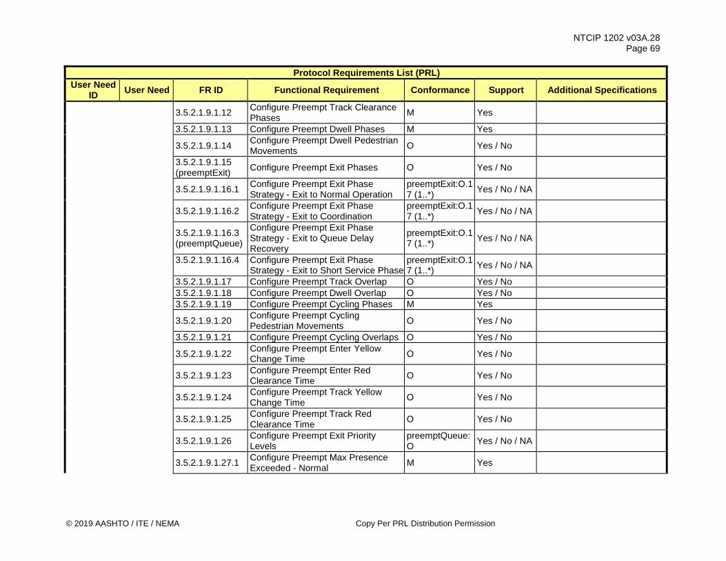
NTCIP 1202 v03A.28 Page 69
© 2019 AASHTO / ITE / NEMA Copy Per PRL Distribution Permission
Protocol Requirements List (PRL) User Need
ID User Need FR ID Functional Requirement Conformance Support Additional Specifications
3.5.2.1.9.1.12 Configure Preempt Track Clearance Phases M Yes
3.5.2.1.9.1.13 Configure Preempt Dwell Phases M Yes
3.5.2.1.9.1.14 Configure Preempt Dwell Pedestrian Movements O Yes / No
3.5.2.1.9.1.15 (preemptExit) Configure Preempt Exit Phases O Yes / No
3.5.2.1.9.1.16.1 Configure Preempt Exit Phase Strategy - Exit to Normal Operation
preemptExit:O.17 (1..*) Yes / No / NA
3.5.2.1.9.1.16.2 Configure Preempt Exit Phase Strategy - Exit to Coordination
preemptExit:O.17 (1..*) Yes / No / NA
3.5.2.1.9.1.16.3 (preemptQueue)
Configure Preempt Exit Phase Strategy - Exit to Queue Delay Recovery
preemptExit:O.17 (1..*) Yes / No / NA
3.5.2.1.9.1.16.4
Configure Preempt Exit Phase Strategy - Exit to Short Service Phase
preemptExit:O.17 (1..*) Yes / No / NA
3.5.2.1.9.1.17 Configure Preempt Track Overlap O Yes / No 3.5.2.1.9.1.18 Configure Preempt Dwell Overlap O Yes / No 3.5.2.1.9.1.19 Configure Preempt Cycling Phases M Yes
3.5.2.1.9.1.20 Configure Preempt Cycling Pedestrian Movements O Yes / No
3.5.2.1.9.1.21 Configure Preempt Cycling Overlaps O Yes / No
3.5.2.1.9.1.22 Configure Preempt Enter Yellow Change Time O Yes / No
3.5.2.1.9.1.23 Configure Preempt Enter Red Clearance Time O Yes / No
3.5.2.1.9.1.24 Configure Preempt Track Yellow Change Time O Yes / No
3.5.2.1.9.1.25 Configure Preempt Track Red Clearance Time O Yes / No
3.5.2.1.9.1.26 Configure Preempt Exit Priority Levels
preemptQueue:O Yes / No / NA
3.5.2.1.9.1.27.1 Configure Preempt Max Presence Exceeded - Normal M Yes

NTCIP 1202 v03A.28 Page 70
Copy Per PRL Distribution Permission © 2019 AASHTO / ITE / NEMA
Protocol Requirements List (PRL) User Need
ID User Need FR ID Functional Requirement Conformance Support Additional Specifications
3.5.2.1.9.1.27.2 Configure Preempt Max Presence Exceeded - All Flash Red O Yes / No
3.5.2.1.9.1.28 Configure Preempt Cycling Phases Sequence M Yes
3.5.2.1.9.1.29 Configure Preempt Enter Minimum Bicycle Time O Yes / No
3.5.2.1.9.1.30 Configure Preempt Enter Bicycle Clearance Time O Yes / No
3.5.2.1.9.1.31 Configure Preempt Cycling Bicycle Phases O Yes / No
3.5.2.1.9.1.32 Configure Preempt Enter Minimum Transit Time O Yes / No
3.5.2.1.9.1.33 Configure Preempt Enter Transit Clearance Time O Yes / No
3.5.2.1.9.1.34 Configure Preempt Cycling Transit Phases O Yes / No
3.5.2.1.9.2.1 Determine Maximum Number of Preempts M Yes The ASC shall support at least
____ preempts 2.5.2.1.10 (Scheduler) Manage Timing Pattern Scheduler O Yes / No
3.5.2.1.10.1.1 Configure Timebase Pattern Synchronization Time M Yes
H.1.1.5.1 Configure Time M Yes

NTCIP 1202 v03A.28 Page 71
© 2019 AASHTO / ITE / NEMA Copy Per PRL Distribution Permission
Protocol Requirements List (PRL) User Need
ID User Need FR ID Functional Requirement Conformance Support Additional Specifications
H.1.1.5.2 Configure Time Zone TimeZone:O Yes / No / NA
Note: Users are cautioned that this object definition has been revised to address interoperability issues in version 01, but remains at the same ObjectID. Pay close attention to the implementation, and interoperability of this object. Place a checkmark below, if the ASC is NOT required to support the major version that is checked. Version v01____ Version v02____
H.1.1.5.3 Configure Daylight Saving Mode DST:O Yes / No / NA H.1.1.5.4 Determine Time Setting M Yes
H.1.1.5.5 (TimeZone) Determine Time Zone Setting O Yes / No
H.1.1.5.6 (DST)
Determine Daylight Saving Mode Setting O Yes / No
H.1.1.7.1 Configure Timebased Scheduler Month-Day-Date M Yes
The ASC shall support at least ____ Schedule Entries (between 1 and 65535). Note: This requirement also appears under User Need ID 2.5.2.1.12 in the PRL.

NTCIP 1202 v03A.28 Page 72
Copy Per PRL Distribution Permission © 2019 AASHTO / ITE / NEMA
Protocol Requirements List (PRL) User Need
ID User Need FR ID Functional Requirement Conformance Support Additional Specifications
H.1.1.7.2 Configure Timebased Scheduler Day Plans and Timebased Actions M Yes
The ASC shall support at least ____ Day Plans (between 1 and 255). The ASC shall support at least ____ Events per Day Plans (between 1 and 255). Note: This requirement also appears under User Need ID 2.5.2.1.12 in the PRL.
H.1.2.3.1 Monitor Timebased Scheduler Month-Day-Date M Yes
H.1.2.3.2 Monitor Timebased Scheduler Day Plans and Timebased Actions M Yes
H.1.2.3.3 Monitor Active Timebased Schedule M Yes
H.1.2.3.4 Monitor Active Timebased Schedule Day Plan and Timebased Actions M Yes
2.5.2.1.11 Manage Action Scheduler Scheduler:M Yes / NA
3.5.2.1.10.1.1 Configure Timebase Pattern Synchronization Time M Yes
3.5.2.1.10.1.2 Configure Timebased Action - Pattern M Yes
3.5.2.1.10.1.3.1 Configure Timebased Action - Auxiliary Function 1 O.18 (1..*) Yes / No
3.5.2.1.10.1.3.2 Configure Timebased Action - Auxiliary Function 2 O.18 (1..*) Yes / No
3.5.2.1.10.1.3.3 Configure Timebased Action - Auxiliary Function 3 O.18 (1..*) Yes / No
3.5.2.1.10.1.3.4 Configure Timebased Action - Dimming
Dimming: O.18 (1..*) Yes / No / NA
3.5.2.1.10.1.4.1 Configure Timebased Action - Special Function 1 O.19 (1..*) Yes / No
3.5.2.1.10.1.4.2 Configure Timebased Action - Special Function 2 O.19 (1..*) Yes / No
3.5.2.1.10.1.4.3 Configure Timebased Action - Special Function 3 O.19 (1..*) Yes / No
3.5.2.1.10.1.4.4 Configure Timebased Action - Special Function 4 O.19 (1..*) Yes / No
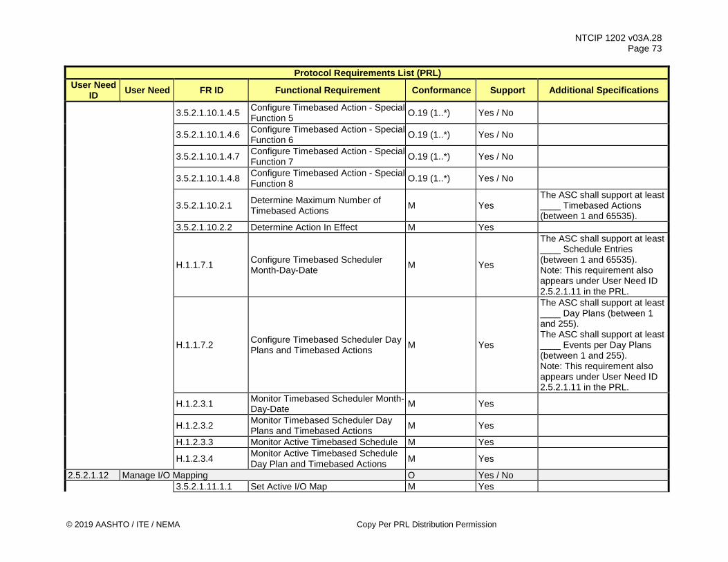
NTCIP 1202 v03A.28 Page 73
© 2019 AASHTO / ITE / NEMA Copy Per PRL Distribution Permission
Protocol Requirements List (PRL) User Need
ID User Need FR ID Functional Requirement Conformance Support Additional Specifications
3.5.2.1.10.1.4.5 Configure Timebased Action - Special Function 5 O.19 (1..*) Yes / No
3.5.2.1.10.1.4.6 Configure Timebased Action - Special Function 6 O.19 (1..*) Yes / No
3.5.2.1.10.1.4.7 Configure Timebased Action - Special Function 7 O.19 (1..*) Yes / No
3.5.2.1.10.1.4.8 Configure Timebased Action - Special Function 8 O.19 (1..*) Yes / No
3.5.2.1.10.2.1 Determine Maximum Number of Timebased Actions M Yes
The ASC shall support at least ____ Timebased Actions (between 1 and 65535).
3.5.2.1.10.2.2 Determine Action In Effect M Yes
H.1.1.7.1 Configure Timebased Scheduler Month-Day-Date M Yes
The ASC shall support at least ____ Schedule Entries (between 1 and 65535). Note: This requirement also appears under User Need ID 2.5.2.1.11 in the PRL.
H.1.1.7.2 Configure Timebased Scheduler Day Plans and Timebased Actions M Yes
The ASC shall support at least ____ Day Plans (between 1 and 255). The ASC shall support at least ____ Events per Day Plans (between 1 and 255). Note: This requirement also appears under User Need ID 2.5.2.1.11 in the PRL.
H.1.2.3.1 Monitor Timebased Scheduler Month-Day-Date M Yes
H.1.2.3.2 Monitor Timebased Scheduler Day Plans and Timebased Actions M Yes
H.1.2.3.3 Monitor Active Timebased Schedule M Yes
H.1.2.3.4 Monitor Active Timebased Schedule Day Plan and Timebased Actions M Yes
2.5.2.1.12 Manage I/O Mapping O Yes / No 3.5.2.1.11.1.1 Set Active I/O Map M Yes

NTCIP 1202 v03A.28 Page 74
Copy Per PRL Distribution Permission © 2019 AASHTO / ITE / NEMA
Protocol Requirements List (PRL) User Need
ID User Need FR ID Functional Requirement Conformance Support Additional Specifications
3.5.2.1.11.1.2.1 Configure I/O Map Description M Yes 3.5.2.1.11.1.2.2.1 Configure I/O Map Input Device M Yes 3.5.2.1.11.1.2.2.2 Configure I/O Map Input Device Pin M Yes 3.5.2.1.11.1.2.2.3 Configure I/O Map Input Function M Yes 3.5.2.1.11.1.2.3.1 Configure I/O Map Output Device M Yes 3.5.2.1.11.1.2.3.2 Configure I/O Map Output Device Pin M Yes 3.5.2.1.11.1.2.3.3 Configure I/O Map Output Function M Yes
3.5.2.1.11.2.1 Retrieve Maximum Number of I/O Maps M Yes
3.5.2.1.11.2.2 Retrieve Maximum Number of I/O Map Inputs M Yes
3.5.2.1.11.2.3 Retrieve Maximum Number of I/O Map Outputs M Yes
3.5.2.1.11.2.4 Retrieve I/O Mapping Activate Conditions M
Yes The following conditions shall be satisfied before a new I/O map can be activated: ___ Cabinet Door Open ___ in any flash state ___ programmed all red flash ___ in CVM flash ___ ASC restart
3.5.2.1.11.2.5 Retrieve I/O Mapping Input Functions M Yes
3.5.2.1.11.2.6 Retrieve I/O Mapping Output Functions M Yes
3.5.2.1.11.2.7 Retrieve I/O Map Input Device Pin Status M Yes
3.5.2.1.11.2.8 Retrieve I/O Map Output Device Pin Status M Yes
3.5.2.1.11.2.9.1 Enumerate I/O Map - FIO Inputs 332:M Yes / NA 3.5.2.1.11.2.9.2 Enumerate I/O Map - FIO Outputs 332:M Yes / NA 3.5.2.1.11.2.9.3 Enumerate I/O Map - TS1 Inputs TS1, TS2-2:M Yes / NA 3.5.2.1.11.2.9.4 Enumerate I/O Map - TS1 Outputs TS1, TS2-2:M Yes / NA 3.5.2.1.11.2.9.5 Enumerate I/O Map - TS2 BIU Inputs TS2-1:M Yes / NA
3.5.2.1.11.2.9.6 Enumerate I/O Map - TS2 BIU Outputs TS2-1:M Yes / NA

NTCIP 1202 v03A.28 Page 75
© 2019 AASHTO / ITE / NEMA Copy Per PRL Distribution Permission
Protocol Requirements List (PRL) User Need
ID User Need FR ID Functional Requirement Conformance Support Additional Specifications
3.5.2.1.11.2.9.7 Enumerate I/O Map - ITS Cabinet SIU Inputs ITS:M Yes / NA
3.5.2.1.11.2.9.8 Enumerate I/O Map - ITS Cabinet SIU Outputs ITS:M Yes / NA
3.5.2.1.11.2.9.9 Enumerate I/O Map - Auxiliary Device Inputs O Yes / No
3.5.2.1.11.2.9.10 Enumerate I/O Map - Auxiliary Device Outputs O Yes / No
2.5.2.1.13 (Intra) Manage Intra-Cabinet Communications Configuration O Yes / No
3.5.2.1.12.1 Determine Serial Bus 1 Device
Present ITS:M Yes / NA The ASC shall support at least ____ Serial Bus 1 Addresses (between 1 and 255).
3.5.2.1.12.2.1 Determine TS2 Port 1 Device Present TS2-2:M Yes / NA The ASC shall support at least ____ TS2 Port1 Addresses (between 1 and 255).
3.5.2.1.12.2.2 Determine TS2 Port 1 Frame 40 Enable TS2-2:M Yes / NA
2.5.2.1.14 Manage ADA Support O Yes / No
3.5.2.1.13.1.1 Configure APS Push Button Minimum Press Time M Yes
3.5.2.1.13.1.2 Configure APS Push Button to Phase Association M Yes
3.5.2.1.13.1.3 Configure APS Extra Crossing Time M Yes
3.5.2.1.13.2 Determine Maximum Number of Pedestrian Buttons M
Yes The ASC shall support at least ____ Pedestrian Push Button inputs (between 1 and 16).
2.5.2.2 Monitor Signal Operations Status 2.5.2.2.1 Determine Controller Health M Yes 3.5.2.2.1.1.1 Monitor Preempt Active Preempt:M Yes / NA 3.5.2.2.1.1.2 Monitor Terminal and Facilities Flash M Yes 3.5.2.2.1.1.3 Monitor Local Cycle Zero Alarm M Yes 3.5.2.2.1.1.4 Monitor Local Override M Yes 3.5.2.2.1.1.5 Monitor Coordination Alarm Coord:M Yes / NA 3.5.2.2.1.1.6 Monitor Detector Fault Detector:M Yes / NA

NTCIP 1202 v03A.28 Page 76
Copy Per PRL Distribution Permission © 2019 AASHTO / ITE / NEMA
Protocol Requirements List (PRL) User Need
ID User Need FR ID Functional Requirement Conformance Support Additional Specifications
3.5.2.2.1.1.7 Monitor Non-Critical Alarm M Yes 3.5.2.2.1.1.8 Monitor Stop Time Input Alarm M Yes 3.5.2.2.1.1.9 Monitor Cycle Fault Alarm M Yes 3.5.2.2.1.1.10 Monitor Coordination Fault Coord:M Yes / NA 3.5.2.2.1.1.11 Monitor Coordination Fail Alarm Coord:M Yes / NA 3.5.2.2.1.1.12 Monitor Cycle Fail Alarm M Yes 3.5.2.2.1.1.13 Monitor SMU Flash Alarm M Yes 3.5.2.2.1.1.14 Monitor Local Flash Alarm M Yes 3.5.2.2.1.1.15 Monitor Local Free Alarm M Yes 3.5.2.2.1.1.16 Monitor Coordination Active Alarm Coord:M Yes / NA 3.5.2.2.1.1.17 Monitor Power Restart Alarm Power:M Yes / NA 3.5.2.2.1.1.18 Monitor Low Battery Alarm Power:O Yes / No / NA 3.5.2.2.1.1.19 Monitor Response Fault Alarm M Yes 3.5.2.2.1.1.20 Monitor External Start M Yes 3.5.2.2.1.1.21 Monitor Stop Time Alarm M Yes 3.5.2.2.1.1.22 Monitor Offset Transitioning Alarm M Yes
3.5.2.2.1.1.23 Monitor Stall Condition M Yes
The vendor shall list the ASC processes or services where a watchdog timer is maintained and is considered critical to the safe operation of the ASC.
3.5.2.2.1.1.24 Monitor Memory Fault M Yes 3.5.2.2.1.1.25 Monitor Process Failure M Yes 3.5.2.2.1.1.26 Monitor Communications Timeout M Yes 3.5.2.2.1.1.27 Monitor Power Problems Power:M Yes / NA 3.5.2.2.1.1.28 Monitor UPS Errors UPS:O Yes / No / NA 3.5.2.2.1.1.29 Monitor Scheduler Errors Scheduler:M Yes / NA
3.5.2.2.1.1.30 Monitor Signal Monitor Communications Error O Yes / No
3.5.2.2.1.1.31 Monitor Signal Monitor Unit Presence O Yes / No 3.5.2.2.1.1.32 Monitor USB Memory Device O Yes / No
3.5.2.2.1.1.33 Monitor ASC Cabinet Temperature Alarm Temp:M Yes / NA
3.5.2.2.1.1.34 Monitor ASC Cabinet Humidity Alarm Humidity:M Yes / NA 3.5.2.2.1.1.35 Monitor Clock Failure M Yes

NTCIP 1202 v03A.28 Page 77
© 2019 AASHTO / ITE / NEMA Copy Per PRL Distribution Permission
Protocol Requirements List (PRL) User Need
ID User Need FR ID Functional Requirement Conformance Support Additional Specifications
3.5.2.2.1.1.36 Monitor Preempt Maximum Presence Alarm Preempt:O Yes / No / NA
3.5.2.2.1.1.37 Monitor RSU Watchdog Timer CV:M Yes / NA 3.5.2.2.1.1.38 Monitor CV Certificate Faults CV:O Yes / No / NA
3.5.2.2.1.2 Monitor Alarm Group State M Yes The ASC shall support at least ____ Alarm Groups (between 1 and 255).
2.5.2.2.2 Determine Mode of Operation 2.5.2.2.2.1 (Unit) Monitor Unit-wide General Operations O Yes / No
3.5.2.2.2.1 Monitor Unit Control Status M Yes 3.5.2.2.2.2 Monitor External Minimum Recall O Yes / No 3.5.2.2.2.3 Monitor Call to Non-Actuated 1 O Yes / No 3.5.2.2.2.4 Monitor Call to Non-Actuated 2 O Yes / No 3.5.2.2.2.5 Monitor Walk Rest Modifier O Yes / No 3.5.2.2.2.6 Monitor Interconnect O Yes / No
3.5.2.2.2.7 (Dimming) Monitor Dimming Enabled O Yes / No
2.5.2.2.2.2 Monitor Flashing Unit:M Yes / NA 3.5.2.2.2.8 Monitor Unit Flash Status M Yes 2.5.2.2.2.3 Monitor Current Timing Pattern Coord:M Yes / NA 3.5.2.2.2.9.1 Monitor Current Pattern Status M Yes 3.5.2.2.2.9.2 Monitor Local Free Status M Yes 3.5.2.2.2.9.3 Monitor Current Mode of Operation M Yes 3.5.2.2.2.9.4 Monitor Programmed Pattern M Yes 2.5.2.2.2.4 Monitor Current Cycle Coord:M Yes / NA 3.5.2.2.2.10.1 Monitor Coordination Cycle Status M Yes
3.5.2.2.2.10.2 Monitor Coordination Synchronization Status M Yes
3.5.2.2.2.10.3 Monitor Current Split M Yes 3.5.2.2.2.10.4 Monitor Current Offset M Yes 2.5.2.2.3 Monitor Signal Indication M Yes
3.5.2.2.3.1 Determine Maximum Number of Phase Groups M
Yes The ASC shall support at least ____ Phase Groups (between 1 and 255).

NTCIP 1202 v03A.28 Page 78
Copy Per PRL Distribution Permission © 2019 AASHTO / ITE / NEMA
Protocol Requirements List (PRL) User Need
ID User Need FR ID Functional Requirement Conformance Support Additional Specifications
3.5.2.2.3.2 Monitor Phase Group Reds M Yes 3.5.2.2.3.3 Monitor Phase Group Yellows M Yes 3.5.2.2.3.4 Monitor Phase Group Greens M Yes 3.5.2.2.3.5 Monitor Phase Group Don't Walks M Yes
3.5.2.2.3.6 Monitor Phase Group Pedestrian Clearance M Yes
3.5.2.2.3.7 Monitor Phase Group Walks M Yes
3.5.2.2.3.8 Monitor Phase Group Flashing Yellow Arrow O Yes / No
3.5.2.2.3.9 Monitor Phase Group Flashing Red Arrow O Yes / No
2.5.2.2.4 Monitor Phase Status M Yes 3.5.2.2.4.1 Monitor Phase Group Phase Ons M Yes 3.5.2.2.4.2 Monitor Phase Group Phase Nexts M Yes 3.5.2.2.4.3 Monitor Phase Group Vehicle Call M Yes 3.5.2.2.4.4 Monitor Phase Group Pedestrian Call M Yes 3.5.2.2.4.5 Monitor Phase Group Bicycle Call Bicycle:M Yes / NA 3.5.2.2.4.6 Monitor Phase Group Transit Call Transit:M Yes / NA 2.5.2.2.5 Monitor Ring Status Ring:M Yes / NA 3.5.2.2.5.1 Monitor Ring Status M Yes 3.5.2.2.5.2 Monitor Ring Termination Cause M Yes 2.5.2.2.6 Monitor Channel Status Channel:M Yes / NA
3.5.2.2.6.1 Determine Maximum Number of Channel Status Groups M Yes
3.5.2.2.6.2 Monitor Channel Status Group Reds M Yes
3.5.2.2.6.3 Monitor Channel Status Group Yellows M Yes
3.5.2.2.6.4 Monitor Channel Status Group Greens M Yes
2.5.2.2.7 Monitor Overlap Status Overlap:M Yes / NA
3.5.2.2.7.1 Determine Maximum Number of Overlap Status Groups M Yes
3.5.2.2.7.2 Monitor Overlap Status Group Reds M Yes
3.5.2.2.7.3 Monitor Overlap Status Group Yellows M Yes

NTCIP 1202 v03A.28 Page 79
© 2019 AASHTO / ITE / NEMA Copy Per PRL Distribution Permission
Protocol Requirements List (PRL) User Need
ID User Need FR ID Functional Requirement Conformance Support Additional Specifications
3.5.2.2.7.4 Monitor Overlap Status Group Greens M Yes
3.5.2.2.7.5 Monitor Overlap Status Group Flashing Yellow Arrows O Yes / No
3.5.2.2.7.6 Monitor Overlap Status Group Flashing Red Arrows O Yes / No
2.5.2.2.8 Monitor Preempt Input State Preempt:M Yes / NA 3.5.2.2.8.1 Monitor Currently Active Preempt M Yes 3.5.2.2.8.2 Monitor Current Preempt Inputs M Yes 2.5.2.2.9 Monitor Preempt State Preempt:O Yes / NA 3.5.2.2.8.3 Monitor Current Preempt State M Yes 3.5.2.2.8.4 Monitor Current Gate Status O Yes / No 2.5.2.2.10 (SpecialFunc)
Monitor Special Function Outputs O Yes / No
3.5.2.2.9.1 Determine Maximum Number of Special Functions M
Yes The ASC shall support at least ____ Special Functions (between 1 and 255).
3.5.2.2.9.3 Monitor Special Function Status M Yes
3.5.2.2.9.4 Monitor Special Function Control Source O Yes / No
2.5.2.2.11 Monitor Timebase Action Status Scheduler:M Yes / NA 3.5.2.2.10.1 Monitor Timebase Action Status M Yes
3.5.2.2.10.2 Monitor Timebase Timing Pattern Status M Yes
2.5.2.2.12 Monitor Intra-Cabinet Communications Configuration O Yes / No 3.5.2.2.11.1 Monitor TS2 Port 1 Status TS2-2:M Yes / NA 3.5.2.2.11.2 Monitor TS2 Port 1 Fault Frame TS2-2:M Yes / NA 3.5.2.2.11.3 Monitor Serial Bus 1 Status ITS:M Yes / NA 2.5.2.3 Control Signal Operations M Yes 2.5.2.3.1 Control ASC-wide General Operations M Yes 3.5.2.3.1.1 Control External Minimum Recall M Yes 3.5.2.3.1.2 Control Call to Non-Actuated 1 M Yes 3.5.2.3.1.3 Control Call to Non-Actuated 2 O Yes / No 3.5.2.3.1.4 Control Walk Rest Modifier M Yes

NTCIP 1202 v03A.28 Page 80
Copy Per PRL Distribution Permission © 2019 AASHTO / ITE / NEMA
Protocol Requirements List (PRL) User Need
ID User Need FR ID Functional Requirement Conformance Support Additional Specifications
3.5.2.3.1.5 Control Interconnect O Yes / No 3.5.2.3.1.6 Control Dimming Enabled Dimming:M Yes / NA 3.5.2.3.1.7 Control Disable Remote Commands O Yes / No 3.5.2.3.1.8 Acknowledge Local Cycle Zero Alarm M Yes
3.5.2.3.1.9 Control Weather-based Signal Operation Changes O Yes / No
2.5.2.3.2 Command Timing Pattern Coord:M Yes / NA 3.5.2.3.2.1 Command System Timing Pattern M Yes
3.5.2.3.2.2 Command System Timing Pattern System Reference Point M Yes
2.5.2.3.3 (PhsCtrl) Phase Requests O Yes / No
3.5.2.3.3.1 Control Phase Group Phase Omits M Yes
3.5.2.3.3.2 Control Phase Group Pedestrian Omits M Yes
3.5.2.3.3.3 Control Phase Group Holds M Yes 3.5.2.3.3.4 Control Phase Group Force Offs O Yes / No 3.5.2.3.3.5 Control Phase Group Vehicle Calls M Yes
3.5.2.3.3.6 Control Phase Group Pedestrian Calls M Yes
3.5.2.3.3.7 Control Phase Group Bicycle Calls Bicycle:M Yes / NA 3.5.2.3.3.8 Control Phase Group Transit Calls Transit:M Yes / NA 2.5.2.3.4 Activate Preempt Preempt:O Yes / No
3.5.2.3.4.1 Command Preempt Remote Activation M Yes
2.5.2.3.5 Control Ring Operations Ring:O Yes / No / NA 3.5.2.3.5.1 Control Ring Stop Time M Yes 3.5.2.3.5.2 Control Ring Force Offs M Yes
3.5.2.3.5.3 Control Ring Maximum 2 Time Settings M Yes
3.5.2.3.5.4 Control Ring Maximum 3 Time Settings O Yes / No
3.5.2.3.5.5 Control Ring Maximum Inhibit Settings M Yes

NTCIP 1202 v03A.28 Page 81
© 2019 AASHTO / ITE / NEMA Copy Per PRL Distribution Permission
Protocol Requirements List (PRL) User Need
ID User Need FR ID Functional Requirement Conformance Support Additional Specifications
3.5.2.3.5.6 Control Ring Pedestrian Recycle Settings M Yes
3.5.2.3.5.7 Control Ring Red Rest Settings M Yes
3.5.2.3.5.8 Control Ring Red Clearance Omit Settings M Yes
3.5.2.3.5.9 Determine Maximum Number of Ring Control Groups M Yes The ASC shall support at least
____ ring control groups. 2.5.2.3.6 Activate Special Function Output SpecialFunc:O Yes / No / NA 3.5.2.3.6.1 Activate Special Function M Yes 3.5.2.3.6.2 Release Special Function Control M Yes
2.5.2.3.7 Control Frame 40 TS1:O TS2-2:O TS2-1:O
Yes / No / NA
3.5.2.3.7.1 Control TS2 Port 1 Frame 40 Messages M Yes
2.5.2.3.8 Activate Action Plan O Yes / No 3.5.2.3.8 Activate Action Plan M Yes 2.5.2.3.9 Remote Manual Control O Yes / No 3.5.2.3.9.1 Enable Manual Control M Yes
3.5.2.3.9.2 Remote Manual Control Advance Command M Yes
3.5.2.3.9.3 Configure Manual Control Timeout M Yes 2.5.3 Manage Detectors 2.5.3.1 (Detector) Manage Detector Configuration M Yes
3.5.3.1.1.1.1 Configure Vehicle Volume Detectors O Yes / No
3.5.3.1.1.1.2 Configure Vehicle Occupancy Detectors O Yes / No
3.5.3.1.1.1.3 (Speed) Configure Vehicle Speed Detectors O Yes / No
3.5.3.1.1.1.4 Configure Vehicle Detection Zone Length O Yes / No
3.5.3.1.1.1.5 Configure Vehicle Travel Mode O Yes / No
3.5.3.1.1.1.6 Configure Vehicle Detector Yellow Lock Call Enabled O Yes / No

NTCIP 1202 v03A.28 Page 82
Copy Per PRL Distribution Permission © 2019 AASHTO / ITE / NEMA
Protocol Requirements List (PRL) User Need
ID User Need FR ID Functional Requirement Conformance Support Additional Specifications
3.5.3.1.1.1.7 Configure Vehicle Detector Red Lock Call Enabled O Yes / No
3.5.3.1.1.1.8 Configure Vehicle Detector Passage Enabled O Yes / No
3.5.3.1.1.1.9 Configure Vehicle Detector Added Initial Time Enabled O Yes / No
3.5.3.1.1.1.10 Configure Vehicle Detector Queue Enabled O Yes / No
3.5.3.1.1.1.11 Configure Vehicle Detector Call Enabled M Yes
3.5.3.1.1.1.12 Configure Vehicle Detector Call Phase M Yes
3.5.3.1.1.1.13 Configure Vehicle Detector Switch Phase M Yes
3.5.3.1.1.1.14 Configure Vehicle Detector Delay Time M Yes
3.5.3.1.1.1.15 Configure Vehicle Detector Extend Time M Yes
3.5.3.1.1.1.16 Configure Vehicle Detector Queue Limit Time O Yes / No
3.5.3.1.1.1.17 Configure Vehicle Detector No Activity Time M Yes
3.5.3.1.1.1.18 Configure Vehicle Detector Maximum Presence Time M Yes
3.5.3.1.1.1.19 Configure Vehicle Detector Erratic Counts M Yes
3.5.3.1.1.1.20 Configure Vehicle Detector Fail Time O Yes / No
3.5.3.1.1.1.21 Configure Single Detector Speed Mode Speed:M Yes / NA
3.5.3.1.1.1.22 Configure Paired Detector Speed:M Yes / NA 3.5.3.1.1.1.23 Configure Paired Detector Placement Speed:M Yes / NA 3.5.3.1.1.1.24 Configure Paired Detector Spacing Speed:M Yes / NA 3.5.3.1.1.1.25 Configure Average Vehicle Length Speed:M Yes / No
3.5.3.1.1.2.1 Configure Pedestrian Detector Call Phase M Yes
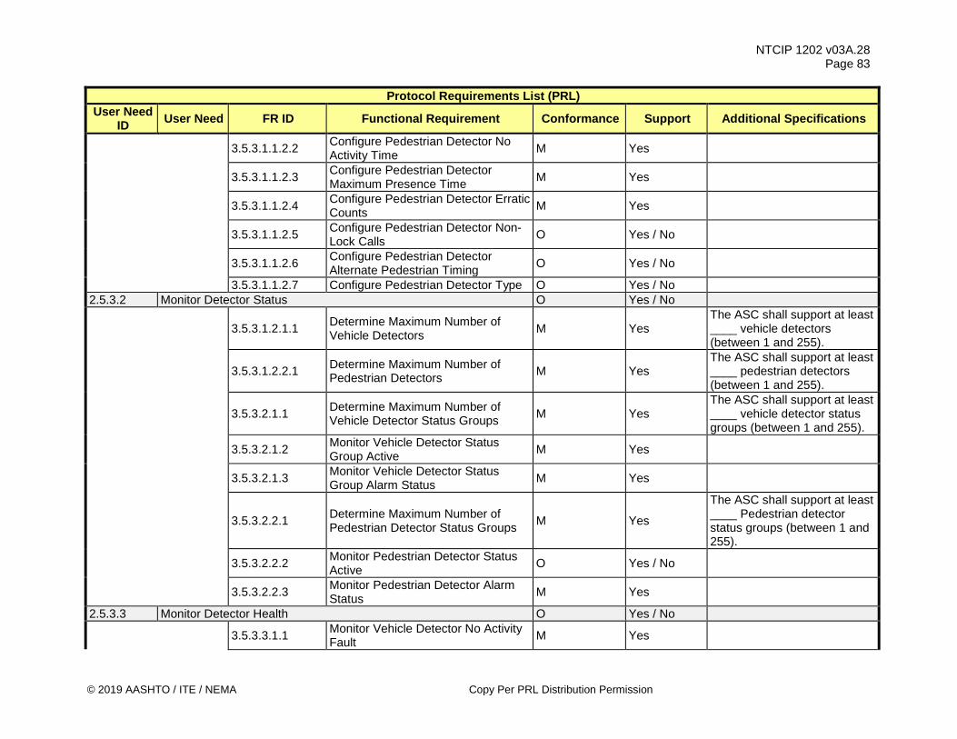
NTCIP 1202 v03A.28 Page 83
© 2019 AASHTO / ITE / NEMA Copy Per PRL Distribution Permission
Protocol Requirements List (PRL) User Need
ID User Need FR ID Functional Requirement Conformance Support Additional Specifications
3.5.3.1.1.2.2 Configure Pedestrian Detector No Activity Time M Yes
3.5.3.1.1.2.3 Configure Pedestrian Detector Maximum Presence Time M Yes
3.5.3.1.1.2.4 Configure Pedestrian Detector Erratic Counts M Yes
3.5.3.1.1.2.5 Configure Pedestrian Detector Non-Lock Calls O Yes / No
3.5.3.1.1.2.6 Configure Pedestrian Detector Alternate Pedestrian Timing O Yes / No
3.5.3.1.1.2.7 Configure Pedestrian Detector Type O Yes / No 2.5.3.2 Monitor Detector Status O Yes / No
3.5.3.1.2.1.1 Determine Maximum Number of Vehicle Detectors M Yes
The ASC shall support at least ____ vehicle detectors (between 1 and 255).
3.5.3.1.2.2.1 Determine Maximum Number of Pedestrian Detectors M Yes
The ASC shall support at least ____ pedestrian detectors (between 1 and 255).
3.5.3.2.1.1 Determine Maximum Number of Vehicle Detector Status Groups M Yes
The ASC shall support at least ____ vehicle detector status groups (between 1 and 255).
3.5.3.2.1.2 Monitor Vehicle Detector Status Group Active M Yes
3.5.3.2.1.3 Monitor Vehicle Detector Status Group Alarm Status M Yes
3.5.3.2.2.1 Determine Maximum Number of Pedestrian Detector Status Groups M Yes
The ASC shall support at least ____ Pedestrian detector status groups (between 1 and 255).
3.5.3.2.2.2 Monitor Pedestrian Detector Status Active O Yes / No
3.5.3.2.2.3 Monitor Pedestrian Detector Alarm Status M Yes
2.5.3.3 Monitor Detector Health O Yes / No
3.5.3.3.1.1 Monitor Vehicle Detector No Activity Fault M Yes
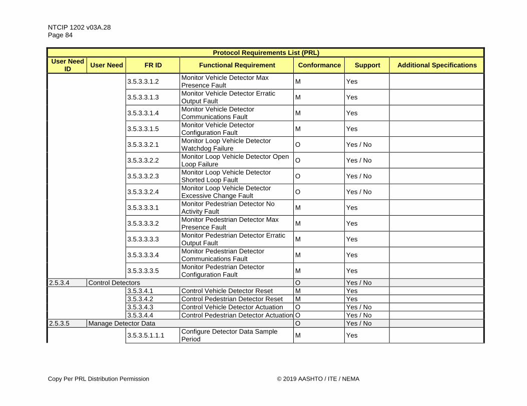
NTCIP 1202 v03A.28 Page 84
Copy Per PRL Distribution Permission © 2019 AASHTO / ITE / NEMA
Protocol Requirements List (PRL) User Need
ID User Need FR ID Functional Requirement Conformance Support Additional Specifications
3.5.3.3.1.2 Monitor Vehicle Detector Max Presence Fault M Yes
3.5.3.3.1.3 Monitor Vehicle Detector Erratic Output Fault M Yes
3.5.3.3.1.4 Monitor Vehicle Detector Communications Fault M Yes
3.5.3.3.1.5 Monitor Vehicle Detector Configuration Fault M Yes
3.5.3.3.2.1 Monitor Loop Vehicle Detector Watchdog Failure O Yes / No
3.5.3.3.2.2 Monitor Loop Vehicle Detector Open Loop Failure O Yes / No
3.5.3.3.2.3 Monitor Loop Vehicle Detector Shorted Loop Fault O Yes / No
3.5.3.3.2.4 Monitor Loop Vehicle Detector Excessive Change Fault O Yes / No
3.5.3.3.3.1 Monitor Pedestrian Detector No Activity Fault M Yes
3.5.3.3.3.2 Monitor Pedestrian Detector Max Presence Fault M Yes
3.5.3.3.3.3 Monitor Pedestrian Detector Erratic Output Fault M Yes
3.5.3.3.3.4 Monitor Pedestrian Detector Communications Fault M Yes
3.5.3.3.3.5 Monitor Pedestrian Detector Configuration Fault M Yes
2.5.3.4 Control Detectors O Yes / No 3.5.3.4.1 Control Vehicle Detector Reset M Yes 3.5.3.4.2 Control Pedestrian Detector Reset M Yes 3.5.3.4.3 Control Vehicle Detector Actuation O Yes / No 3.5.3.4.4 Control Pedestrian Detector Actuation O Yes / No 2.5.3.5 Manage Detector Data O Yes / No
3.5.3.5.1.1.1 Configure Detector Data Sample Period M Yes

NTCIP 1202 v03A.28 Page 85
© 2019 AASHTO / ITE / NEMA Copy Per PRL Distribution Permission
Protocol Requirements List (PRL) User Need
ID User Need FR ID Functional Requirement Conformance Support Additional Specifications
3.5.3.5.1.1.2 Configure Detector Data Sample Period - Version 3 M Yes
3.5.3.5.2.1.1 Monitor Detector Data Sequence M Yes
3.5.3.5.2.1.2 Determine Detector Data Active Detectors M Yes
3.5.3.5.2.1.3 Monitor Volume Data O Yes / No 3.5.3.5.2.1.4 Monitor Average Speed Speed:M Yes / NA 3.5.3.5.2.1.5 Monitor Occupancy Data O Yes / No 3.5.3.5.2.1.6 Monitor Vehicle Detector Data Alarms M Yes 3.5.3.5.2.1.7 Monitor Detector Data Sample Time M Yes
3.5.3.5.2.1.8 Monitor Detector Data Sample Duration M Yes
3.5.3.6.1.1 Configure Pedestrian Data Collection Sample Period M Yes / No
3.5.3.6.2.1 Monitor Pedestrian Counts O Yes / No
3.5.3.6.2.2 Monitor Pedestrian Detector Actuations O Yes / No
3.5.3.6.2.3 Monitor Pedestrian Detector Data Alarms O Yes / No
3.5.3.6.2.4 Monitor Pedestrian Services O Yes / No
3.5.3.6.2.5 Determine Pedestrian Detector Data Active Detectors O Yes / No
3.5.3.6.2.6 Monitor Pedestrian Detector Data Sample Time O Yes / No
3.5.3.6.2.7 Monitor Pedestrian Detector Data Sample Duration O Yes / No
3.5.3.6.2.8 Monitor Pedestrian Detector Data Sequence O Yes / No
2.5.4 (CV) Manage Connected Vehicles Interface O Yes / No
2.5.4.1 Connected Vehicle Manager: Management Station – ASC Interface M Yes / No 2.5.4.1.1 Manage RSU Interface M Yes 3.5.4.1.1.1 Configure RSU Interface M Yes 3.5.4.1.1.2 Configure Logical RSU Ports M Yes

NTCIP 1202 v03A.28 Page 86
Copy Per PRL Distribution Permission © 2019 AASHTO / ITE / NEMA
Protocol Requirements List (PRL) User Need
ID User Need FR ID Functional Requirement Conformance Support Additional Specifications
3.5.4.1.1.3 Configure RSU Interface Polling Period O Yes / No
2.5.4.1.2 Manage RSU Interface Watchdog O Yes / No 3.5.4.1.2.1 Configure RSU Interface Watchdog M Yes
3.5.4.1.2.2 Monitor RSU Interface Watchdog Timer M Yes
2.5.4.1.3 Manage Signal Phase and Timing Data O Yes / No
3.5.4.1.3.1 Enable Signal Phase and Timing Data M Yes
3.5.4.1.3.2 Retrieve Intersection Identifier M Yes
3.5.4.1.3.3 Retrieve Signal Phase and Timing Time Point M Yes
3.5.4.1.3.4 Retrieve Signal Phase and Timing Generation Time M Yes
3.5.4.1.3.5 Retrieve Signal Phase and Timing Intersection Status M Yes
3.5.4.1.3.6.1 Monitor Movement State M Yes
3.5.4.1.3.6.2.1 Monitor Movement Minimum End Time O Yes / No
3.5.4.1.3.6.2.2 Monitor Movement Maximum End Time O Yes / No
3.5.4.1.3.6.2.3 Monitor Movement Likely End Time O Yes / No
3.5.4.1.3.6.2.4 Monitor Movement Likely End Time Confidence O Yes / No
3.5.4.1.3.6.2.5 Monitor Movement Next Occurrence O Yes / No
3.5.4.1.3.6.3.1 Configure Queue Detectors for Movement Assistance MvtQueue:M Yes / NA
3.5.4.1.3.6.3.2 Configure Pedestrian Detectors for Movement Assistance
MvtConflict:O.13 (1..*) Yes / No / NA
3.5.4.1.3.6.3.3 Configure Bicycle Detectors for Movement Assistance
MvtConflict:O.13 (1..*) Yes / No / NA
3.5.4.1.3.6.4.1 (MvtQueue)
Monitor Lane Connection Queue Length O Yes / No
3.5.4.1.3.6.4.2 Monitor Lane Connection Available Storage Length O Yes / No

NTCIP 1202 v03A.28 Page 87
© 2019 AASHTO / ITE / NEMA Copy Per PRL Distribution Permission
Protocol Requirements List (PRL) User Need
ID User Need FR ID Functional Requirement Conformance Support Additional Specifications
3.5.4.1.3.6.4.3 Monitor Lane Connection Stop Line Wait O Yes / No
3.5.4.1.3.6.4.4 (MvtConflict)
Monitor Lane Connection Traveler Detection O Yes / No
3.5.4.1.3.6.4.5 Monitor Lane Connection State M Yes
3.5.4.1.3.6.5.1 (SpdAdvice) Configure Advisory Speed Type O Yes / No
3.5.4.1.3.6.5.2 Configure Advisory Speed SpdAdvice:O Yes / No / NA 3.5.4.1.3.6.5.3 Configure Advisory Speed Zone SpdAdvice:O Yes / No / NA
3.5.4.1.3.6.5.4 Configure Advisory Speed Vehicle Type SpdAdvice:O Yes / No / NA
3.5.4.1.3.6.5.5 Retrieve Advisory Speed Confidence Level SpdAdvice:O Yes / No / NA
3.5.4.1.3.6.6 Monitor Movement Status O Yes / No
3.5.4.1.3.6.7 Monitor Lane Connection Maneuver Status O Yes / No
3.5.4.1.3.7.1 Configure Concurrent Enabled Lanes O Yes / No
3.5.4.1.3.7.2 Configure Enabled Lanes for a Pattern O Yes / No
3.5.4.1.3.7.3 Command Enabled Lanes O Yes / No 3.5.4.1.3.8 Configure Movement Type M Yes 3.5.4.1.3.9 Configure Lane Connection Type M Yes
3.5.4.1.3.10 Enable Signal Phase and Timing Data Exchange O Yes / No
2.5.4.1.4 Exchange Connected Devices Data for Operational Performance Data Perform:O Yes / No / NA
3.5.1.5.1.1 Enable/Disable Collection of Operational Performance Data M Yes
3.5.1.5.1.2 Start Collection of Operational Performance Data on Specific Date/Time
O Yes / No
3.5.1.5.1.3 End Collection of Operational Performance Data on Specific Date/Time
O Yes / No
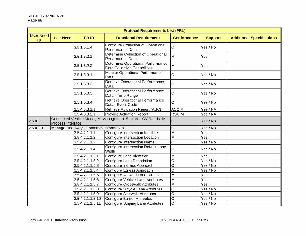
NTCIP 1202 v03A.28 Page 88
Copy Per PRL Distribution Permission © 2019 AASHTO / ITE / NEMA
Protocol Requirements List (PRL) User Need
ID User Need FR ID Functional Requirement Conformance Support Additional Specifications
3.5.1.5.1.4 Configure Collection of Operational Performance Data O Yes / No
3.5.1.5.2.1 Determine Collection of Operational Performance Data M Yes
3.5.1.5.2.2 Determine Operational Performance Data Collection Capabilities M Yes
3.5.1.5.3.1 Monitor Operational Performance Data O Yes / No
3.5.1.5.3.2 Retrieve Operational Performance Data O Yes / No
3.5.1.5.3.3 Retrieve Operational Performance Data - Time Range O Yes / No
3.5.1.5.3.4 Retrieve Operational Performance Data - Event Code O Yes / No
3.5.4.3.3.1.1 Retrieve Actuation Report (ASC) ASC:M Yes / NA 3.5.4.3.3.2.1 Provide Actuation Report RSU:M Yes / NA
2.5.4.2 Connected Vehicle Manager: Management Station – CV Roadside Process Interface O Yes / No
2.5.4.2.1 Manage Roadway Geometrics Information O Yes / No 3.5.4.2.1.1.1 Configure Intersection Identifier M Yes 3.5.4.2.1.1.2 Configure Intersection Location M Yes 3.5.4.2.1.1.3 Configure Intersection Name O Yes / No
3.5.4.2.1.1.4 Configure Intersection Default Lane Width O Yes / No
3.5.4.2.1.1.5.1 Configure Lane Identifier M Yes 3.5.4.2.1.1.5.2 Configure Lane Description O Yes / No 3.5.4.2.1.1.5.3 Configure Ingress Approach O Yes / No 3.5.4.2.1.1.5.4 Configure Egress Approach O Yes / No 3.5.4.2.1.1.5.5 Configure Allowed Lane Direction M Yes 3.5.4.2.1.1.5.6 Configure Vehicle Lane Attributes M Yes 3.5.4.2.1.1.5.7 Configure Crosswalk Attributes M Yes 3.5.4.2.1.1.5.8 Configure Bicycle Lane Attributes O Yes / No 3.5.4.2.1.1.5.9 Configure Sidewalk Attributes O Yes / No 3.5.4.2.1.1.5.10 Configure Barrier Attributes O Yes / No 3.5.4.2.1.1.5.11 Configure Striping Lane Attributes O Yes / No

NTCIP 1202 v03A.28 Page 89
© 2019 AASHTO / ITE / NEMA Copy Per PRL Distribution Permission
Protocol Requirements List (PRL) User Need
ID User Need FR ID Functional Requirement Conformance Support Additional Specifications
3.5.4.2.1.1.5.12 Configure Tracked Lane Attributes O Yes / No 3.5.4.2.1.1.5.13 Configure Parked Lane Attributes O Yes / No 3.5.4.2.1.1.5.14 Configure Shared Lanes Attributes M Yes 3.5.4.2.1.1.5.15 Configure Allowed Maneuvers O Yes / No 3.5.4.2.1.1.5.16 Configure Lane Path M Yes 3.5.4.2.1.1.6.1 Configure Node Point Attributes O Yes / No 3.5.4.2.1.1.6.2 Configure Lane Segment Attributes O Yes / No 3.5.4.2.1.1.6.3 Configure Lane End Point Angle O Yes / No 3.5.4.2.1.1.6.4 Configure Lane Crown Angle - Center O Yes / No
3.5.4.2.1.1.6.5 Configure Lane Crown Angle - Left Edge O Yes / No
3.5.4.2.1.1.6.6 Configure Lane Crown Angle - Right Edge O Yes / No
3.5.4.2.1.1.6.7 Configure Lane Angle O Yes / No
3.5.4.2.1.1.6.8 (SpeedLimit) Configure Speed Limit Type at Node O Yes / No
3.5.4.2.1.1.6.9 Configure Speed Limit at Node SpeedLimit:O Yes / No / NA 3.5.4.2.1.1.6.10 Configure Lane Width Delta O Yes / No 3.5.4.2.1.1.6.11 Configure Lane Elevation Delta O Yes / No
3.5.4.2.1.1.7.1 (Computed) Configure Computed Lane Reference O Yes / No
3.5.4.2.1.1.7.2 Configure Computed Lane X Offset Computed:M Yes / NA 3.5.4.2.1.1.7.3 Configure Computed Lane Y Offset Computed:M Yes / NA 3.5.4.2.1.1.7.4 Configure Computed Lane Rotation Computed:O Yes / No / NA 3.5.4.2.1.1.7.5 Configure Computed Lane X Scale Computed:O Yes / No / NA 3.5.4.2.1.1.7.6 Configure Computed Lane Y Scale Computed:O Yes / No / NA 3.5.4.2.1.1.8 Configure Overlays O Yes / No
3.5.4.2.1.1.9 (RestrictClass) Configure Applicable Users O Yes / No
3.5.4.2.1.2.1 Determine Maximum Number of Intersections Supported M Yes
The ASC shall support at least ____ (1-255) intersection definitions.
3.5.4.2.1.2.2 Determine Maximum Number of Lanes Supported M Yes The ASC shall support at least
____ (1-255) lane definitions.

NTCIP 1202 v03A.28 Page 90
Copy Per PRL Distribution Permission © 2019 AASHTO / ITE / NEMA
Protocol Requirements List (PRL) User Need
ID User Need FR ID Functional Requirement Conformance Support Additional Specifications
3.5.4.2.1.2.3 Determine Maximum Number of Computed Lanes Supported Computed:M Yes The ASC shall support at least
____ (1-255) computed lanes.
3.5.4.2.1.2.4 Determine Maximum Number of
Node Points Supported M Yes The ASC shall support at least ____ (2-63) node points for a lane.
3.5.4.2.1.2.5 Determine Maximum Number of Speed Limits Supported SpeedLimit:M Yes The ASC shall support at least
____ (1-9) speed limit types.
3.5.4.2.1.2.6 Determine Maximum Number of Vehicle Type Definitions RestrictClass:M Yes The ASC shall support at least
____ (1-255).
3.5.4.2.1.3.1 Configure Roadway Geometry Plan Process Method O Yes / No
3.5.4.2.1.3.2 Configure Roadway Geometry Plan Process Agency O Yes / No
3.5.4.2.1.3.3 Configure Roadway Geometry Plan Date O Yes / No
3.5.4.2.1.3.4 Configure Roadway Geometry Plan Geoid O Yes / No
3.5.4.2.1.3.5 Configure Roadway Geometry Plan Layer Type O Yes / No
3.5.4.2.1.3.6 Configure Roadway Geometry Plan Layer Identifier O Yes / No
2.5.4.2.2 Manage Movement Configuration for Connected Devices O Yes / No 3.5.4.2.2.1.1 Configure Connecting Lane M Yes 3.5.4.2.2.1.2 Configure Connecting Maneuver M Yes
3.5.4.2.2.1.3 Configure Remote Intersection Identifier O Yes / No
3.5.4.2.2.1.4 Configure Matching Signal Group M Yes 3.5.4.2.2.2 Configure Lane Connection Users O Yes / No 3.5.4.2.2.3 Configure Connection Identifier O Yes / No 3.5.4.2.2.4 Configure MAP Plans O Yes / No
3.5.4.2.2.5 Determine Maximum Number of Signal Groups Supported M Yes
3.5.4.2.2.6 Determine Maximum Number of Lane Connections Supported M Yes
3.5.4.2.2.7 Command MAP Plans O Yes / No
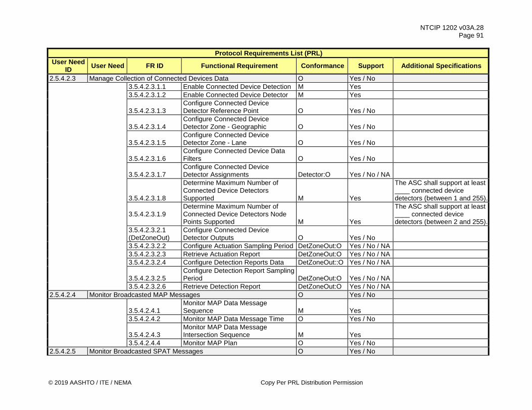
NTCIP 1202 v03A.28 Page 91
© 2019 AASHTO / ITE / NEMA Copy Per PRL Distribution Permission
Protocol Requirements List (PRL) User Need
ID User Need FR ID Functional Requirement Conformance Support Additional Specifications
2.5.4.2.3 Manage Collection of Connected Devices Data O Yes / No 3.5.4.2.3.1.1 Enable Connected Device Detection M Yes 3.5.4.2.3.1.2 Enable Connected Device Detector M Yes
3.5.4.2.3.1.3 Configure Connected Device Detector Reference Point O Yes / No
3.5.4.2.3.1.4 Configure Connected Device Detector Zone - Geographic O Yes / No
3.5.4.2.3.1.5 Configure Connected Device Detector Zone - Lane O Yes / No
3.5.4.2.3.1.6 Configure Connected Device Data Filters O Yes / No
3.5.4.2.3.1.7 Configure Connected Device Detector Assignments Detector:O Yes / No / NA
3.5.4.2.3.1.8
Determine Maximum Number of Connected Device Detectors Supported M Yes
The ASC shall support at least ____ connected device detectors (between 1 and 255).
3.5.4.2.3.1.9 Determine Maximum Number of Connected Device Detectors Node Points Supported M Yes
The ASC shall support at least ____ connected device detectors (between 2 and 255).
3.5.4.2.3.2.1 (DetZoneOut)
Configure Connected Device Detector Outputs O Yes / No
3.5.4.2.3.2.2 Configure Actuation Sampling Period DetZoneOut:O Yes / No / NA 3.5.4.2.3.2.3 Retrieve Actuation Report DetZoneOut:O Yes / No / NA 3.5.4.2.3.2.4 Configure Detection Reports Data DetZoneOut::O Yes / No / NA
3.5.4.2.3.2.5 Configure Detection Report Sampling Period DetZoneOut:O Yes / No / NA
3.5.4.2.3.2.6 Retrieve Detection Report DetZoneOut:O Yes / No / NA 2.5.4.2.4 Monitor Broadcasted MAP Messages O Yes / No
3.5.4.2.4.1 Monitor MAP Data Message Sequence M Yes
3.5.4.2.4.2 Monitor MAP Data Message Time O Yes / No
3.5.4.2.4.3 Monitor MAP Data Message Intersection Sequence M Yes
3.5.4.2.4.4 Monitor MAP Plan O Yes / No 2.5.4.2.5 Monitor Broadcasted SPAT Messages O Yes / No
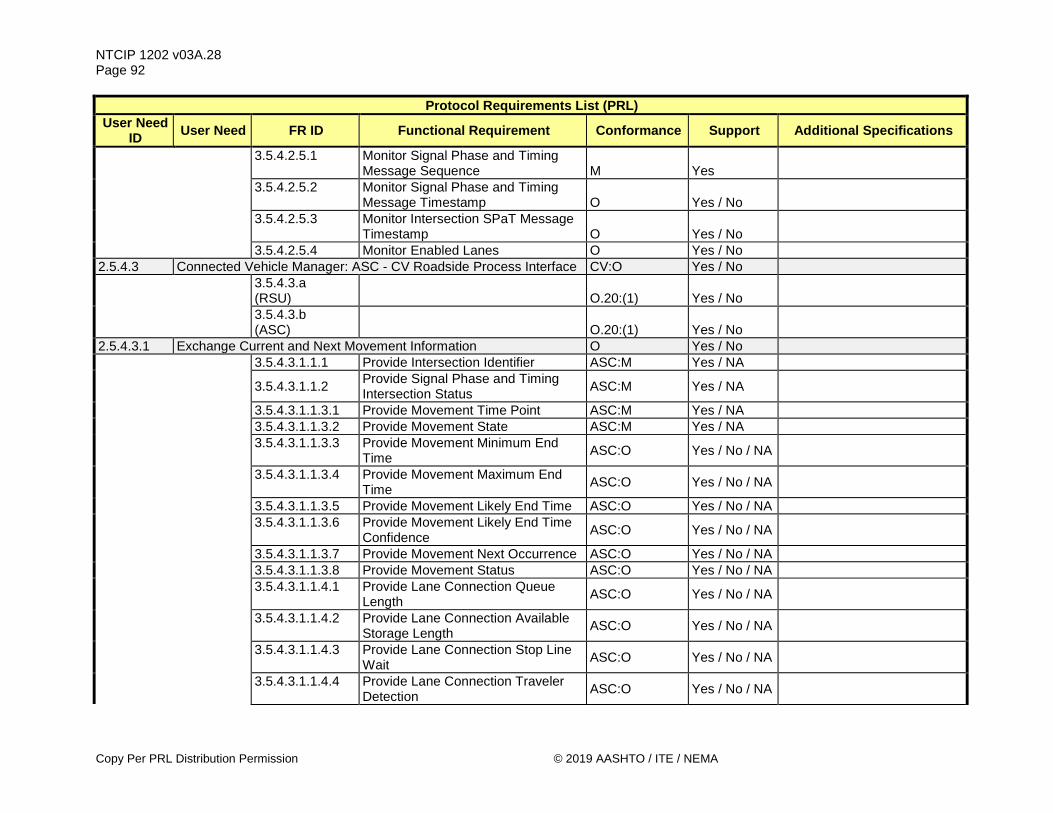
NTCIP 1202 v03A.28 Page 92
Copy Per PRL Distribution Permission © 2019 AASHTO / ITE / NEMA
Protocol Requirements List (PRL) User Need
ID User Need FR ID Functional Requirement Conformance Support Additional Specifications
3.5.4.2.5.1 Monitor Signal Phase and Timing Message Sequence M Yes
3.5.4.2.5.2 Monitor Signal Phase and Timing Message Timestamp O Yes / No
3.5.4.2.5.3 Monitor Intersection SPaT Message Timestamp O Yes / No
3.5.4.2.5.4 Monitor Enabled Lanes O Yes / No 2.5.4.3 Connected Vehicle Manager: ASC - CV Roadside Process Interface CV:O Yes / No
3.5.4.3.a (RSU) O.20:(1) Yes / No
3.5.4.3.b (ASC) O.20:(1) Yes / No
2.5.4.3.1 Exchange Current and Next Movement Information O Yes / No 3.5.4.3.1.1.1 Provide Intersection Identifier ASC:M Yes / NA
3.5.4.3.1.1.2 Provide Signal Phase and Timing Intersection Status ASC:M Yes / NA
3.5.4.3.1.1.3.1 Provide Movement Time Point ASC:M Yes / NA 3.5.4.3.1.1.3.2 Provide Movement State ASC:M Yes / NA
3.5.4.3.1.1.3.3 Provide Movement Minimum End Time ASC:O Yes / No / NA
3.5.4.3.1.1.3.4 Provide Movement Maximum End Time ASC:O Yes / No / NA
3.5.4.3.1.1.3.5 Provide Movement Likely End Time ASC:O Yes / No / NA
3.5.4.3.1.1.3.6 Provide Movement Likely End Time Confidence ASC:O Yes / No / NA
3.5.4.3.1.1.3.7 Provide Movement Next Occurrence ASC:O Yes / No / NA 3.5.4.3.1.1.3.8 Provide Movement Status ASC:O Yes / No / NA
3.5.4.3.1.1.4.1 Provide Lane Connection Queue Length ASC:O Yes / No / NA
3.5.4.3.1.1.4.2 Provide Lane Connection Available Storage Length ASC:O Yes / No / NA
3.5.4.3.1.1.4.3 Provide Lane Connection Stop Line Wait ASC:O Yes / No / NA
3.5.4.3.1.1.4.4 Provide Lane Connection Traveler Detection ASC:O Yes / No / NA

NTCIP 1202 v03A.28 Page 93
© 2019 AASHTO / ITE / NEMA Copy Per PRL Distribution Permission
Protocol Requirements List (PRL) User Need
ID User Need FR ID Functional Requirement Conformance Support Additional Specifications
3.5.4.3.1.1.4.5 Provide Lane Connection State ASC:O Yes / No / NA 3.5.4.3.1.1.4.6 Provide Lane Connection Status ASC:O Yes / No / NA 3.5.4.3.1.1.5.1 Provide Advisory Speed Type ASC:O Yes / No / NA 3.5.4.3.1.1.5.2 Provide Advisory Speed ASC:O Yes / No / NA 3.5.4.3.1.1.5.3 Provide Advisory Speed Zone ASC:O Yes / No / NA 3.5.4.3.1.1.5.4 Provide Advisory Speed Vehicle Type ASC:O Yes / No / NA
3.5.4.3.1.1.5.5 Provide Advisory Speed Confidence Level ASC:O Yes / No / NA
3.5.4.3.1.1.6 Provide Intersection Channel Assignment ASC:M Yes / NA
3.5.4.3.1.2.1 Retrieve Intersection Identifier RSU:M Yes / NA
3.5.4.3.1.2.2 Retrieve Signal Phase and Timing Intersection Status RSU:M Yes / NA
3.5.4.3.1.2.3.1 Retrieve Movement Time Point RSU:M Yes / NA
3.5.4.3.1.2.3.2 Retrieve Movement Time Point - Milliseconds RSU:O Yes / No / NA
3.5.4.3.1.2.3.3 Retrieve Movement State RSU:M Yes / NA
3.5.4.3.1.2.3.4 Retrieve Movement Minimum End Time RSU:O Yes / No / NA
3.5.4.3.1.2.3.5 Retrieve Movement Maximum End Time RSU:O Yes / No / NA
3.5.4.3.1.2.3.6 Retrieve Movement Likely End Time RSU:O Yes / No / NA
3.5.4.3.1.2.3.7 Retrieve Movement Likely End Time Confidence RSU:O Yes / No / NA
3.5.4.3.1.2.3.8 Retrieve Movement Next Occurrence RSU:O Yes / No / NA 3.5.4.3.1.2.3.9 Retrieve Movement Status RSU:O Yes / No / NA
3.5.4.3.1.2.4.1 Retrieve Lane Connection Queue Length RSU:O Yes / No / NA
3.5.4.3.1.2.4.2 Retrieve Lane Connection Available Storage Length RSU:O Yes / No / NA
3.5.4.3.1.2.4.3 Retrieve Lane Connection Stop Line Wait RSU:O Yes / No / NA
3.5.4.3.1.2.4.4 Retrieve Lane Connection Traveler Detection RSU:O Yes / No / NA
3.5.4.3.1.2.4.5 Retrieve Lane Connection State RSU:O Yes / No / NA

NTCIP 1202 v03A.28 Page 94
Copy Per PRL Distribution Permission © 2019 AASHTO / ITE / NEMA
Protocol Requirements List (PRL) User Need
ID User Need FR ID Functional Requirement Conformance Support Additional Specifications
3.5.4.3.1.2.4.6 Retrieve Lane Connection Status RSU:O Yes / No / NA 3.5.4.3.1.2.5.1 Retrieve Advisory Speed Type RSU:O Yes / No / NA 3.5.4.3.1.2.5.2 Retrieve Advisory Speed RSU:O Yes / No / NA 3.5.4.3.1.2.5.3 Retrieve Advisory Speed Zone RSU:O Yes / No / NA
3.5.4.3.1.2.5.4 Retrieve Advisory Speed Vehicle Type RSU:O Yes / No / NA
3.5.4.3.1.2.5.5 Retrieve Advisory Speed Confidence Level RSU:O Yes / No / NA
3.5.4.3.1.2.6 Retrieve Intersection Channel Assignment RSU:M Yes / NA
3.6.3.1 SPaT Maximum Transmission Start Time ASC:M Yes / NA
The Maximum Transmission Start Time for all SPAT data shall be ___ milliseconds (Default=10).
3.6.3.2 Movement Time Point Minimum Transmission Rate ASC:M Yes / NA
The Movement Time Point Minimum Transmission Rate shall be once per _____ milliseconds (Default=100).
3.6.3.3 SPaT-data Request Transmission Rate RSU:M Yes / NA
The nominal Rate to request SPAT-data from an ASC shall be once per ___ milliseconds (Default=100).
3.6.3.4 Condition-based SPaT Maximum Transmission Start Time RSU, Traps:O Yes / No / NA
The Maximum Transmission Start Time for all SPAT reports shall be ___ milliseconds (Default=10).
3.6.3.5 SPaT Latency M Yes 2.5.4.3.2 Exchange Next Occurrence of a Movement O Yes / No 3.5.4.3.2.1 Provide Movement Next Occurrence ASC:M Yes / NA 3.5.4.3.2.2 Retrieve Movement Next Occurrence RSU:M Yes / NA
3.6.3.1 SPaT Maximum Transmission Start Time ASC:M Yes / NA
The Maximum Transmission Start Time for all SPAT data that changed shall be ___ milliseconds (Default=10).

NTCIP 1202 v03A.28 Page 95
© 2019 AASHTO / ITE / NEMA Copy Per PRL Distribution Permission
Protocol Requirements List (PRL) User Need
ID User Need FR ID Functional Requirement Conformance Support Additional Specifications
3.6.3.2 Movement Time Point Minimum Transmission Rate ASC:M Yes / NA
The Movement Time Point Minimum Transmission Rate shall be once per _____ milliseconds (Default=100).
3.6.3.3 SPaT-data Request Transmission Rate RSU:M Yes / NA
The nominal Rate to request SPAT-data from an ASC shall be once per ___ milliseconds (Default=100).
3.6.3.4 Condition-based SPaT Maximum Transmission Start Time RSU, Traps:O Yes / No / NA
The Maximum Transmission Start Time for all SPAT reports shall be ___ milliseconds (Default=10).
3.6.3.5 SPaT Latency M Yes 2.5.4.3.3 Exchange Presence of Connected Devices O Yes / No 3.5.4.3.3.1.1 Retrieve Actuation Report (ASC) ASC:O.21(1..*) Yes / No / NA 3.5.4.3.3.1.2 Retrieve Detection Report (ASC) ASC:O.21(1..*) Yes / No / NA 3.5.4.3.3.2.1 Provide Actuation Report RSU:O.22(1..*) Yes / No / NA 3.5.4.3.3.2.2 Provide Detection Report RSU:O.22(1..*) Yes / No / NA 2.5.4.3.4 Exchange Roadway Geometrics Information O Yes / No 3.5.4.3.4.1.1 Retrieve MAP Plan in Effect ASC:M Yes / NA 3.5.4.3.4.2.1 Provide MAP Plan in Effect RSU:M Yes / NA 3.5.4.3.4.3 Confirm MAP Plan Compatibility M Yes 2.5.5 Backward Compatibility Features 2.5.5.1 Backward Compatible with NTCIP 1202 v01 O Yes / No .
3.5.5.1 NTCIP 1202 v01 - Configure Special Function State O Yes / No
2.5.5.2 Backward Compatible with NTCIP 1202 v02 NA NA 2.6 Security M Yes 2.6.1 Manage Authentication M Yes H.1.1.8.1 Configure Security Definitions M Yes H.1.2.4.1 Determine Security Definitions M Yes 2.6.2 Manage Accessibility M Yes 3.4.4.1 Configure Access M Yes 3.4.4.2 Determine Current Access Settings M Yes 2.6.3 Manage Users M Yes

NTCIP 1202 v03A.28 Page 96
Copy Per PRL Distribution Permission © 2019 AASHTO / ITE / NEMA
Protocol Requirements List (PRL) User Need
ID User Need FR ID Functional Requirement Conformance Support Additional Specifications
3.4.4.1 Configure Access M Yes 3.4.4.2 Determine Current Access Settings M Yes 2.6.4 Log User Access O Yes/No 3.5.1.6.1 Configure ASC Clock Source O Yes / No 3.5.1.6.2 Determine ASC Clock Status O Yes / No 3.5.1.6.3 Determine Current ASC Clock Source O Yes / No
3.5.1.6.4 Determine Available ASC Clock Sources
O Yes / No
H.1.1.5.1 Configure Time M Yes H.1.1.5.2 Configure Time Zone TimeZone:O Yes / No / NA H.1.1.5.3 Configure Daylight Saving Mode DST:O Yes / No / NA H.1.1.5.4 Determine Time Setting M Yes
H.1.1.5.5 (TimeZone) Determine Time Zone Setting O Yes / No
H.1.1.5.6 (DST) Determine Daylight Saving Mode Setting
O Yes / No
H.1.1.5.7 Monitor Current Time M Yes
H.1.3.1.1 Retrieve Current Configuration of Logging Service
M Yes
H.1.3.1.2 Configure Event Logging Service M Yes H.1.3.1.3 Retrieve Event Logged Data M Yes
H.1.3.1.5 Determine Capabilities of Event Logging Service
M Yes
H.1.3.1.6 Determine Number of Logged Events per Event Class
M Yes
H.1.3.1.7 Support a Number of Events to Store in Log
M Yes The ASC shall be capable of storing at least ____ events in the event log file (up to 65535).
H.1.3.1.9 Determine Total Number of Logged Events
O Yes / No
H.1.3.1.10 Determine Number of Events within a Class
M Yes
H.1.3.2.1 Record and Timestamp Events M Yes
H.1.3.2.2 Support a Number of Event Classes M Yes The ASC shall support at least ____ event classes.

NTCIP 1202 v03A.28 Page 97
© 2019 AASHTO / ITE / NEMA Copy Per PRL Distribution Permission
Protocol Requirements List (PRL) User Need
ID User Need FR ID Functional Requirement Conformance Support Additional Specifications
H.1.3.2.3 Support a Number of Events to Log M Yes The ASC shall be able to log at least ____ events.
H.1.3.2.4.1 Support On-Change Events M Yes H.1.3.2.4.6 Support Bit Flag Events M Yes
H.1.3.2.4.7 Support Event Monitoring on Any Data
M Yes
3.6.1 Response Time for Requests
M Yes The Response Time for all requests shall be ___ milliseconds (5-500: Default=25).

NTCIP 1202 v03A.28 Page 98
Do Not Copy Without Written Permission © 2019 AASHTO / ITE / NEMA
3.4 Architectural Requirements Requirements for communication capabilities follow.
3.4.1 Support Basic Communications Requirements Requirements for making requests follow.
3.4.1.1 Retrieve Data Upon request from a management station, the ASC shall provide the data requested.
3.4.1.2 Deliver Data Upon request from a management station, the ASC shall receive the data (e.g., configuration data, commands, etc.) provided.
3.4.1.3 Explore Data Upon request from a management station, the ASC shall allow dynamic discovery of the data concepts and data instances supported by the ASC.
3.4.2 Support Logged Data Requirements The requirements for managing the logged data are defined in Annex H.1.3.
3.4.3 Support Exception Reporting Requirements The requirements for exception reporting are defined in Annex H.1.1.10.
3.4.4 Manage Access Requirements The requirements for ASC access management follow.
3.4.4.1 Configure Access Upon request from a management station, the ASC shall allow the administrator at the management station to configure access settings for all access levels. The agency specification identifies the number of access levels that the ASC is required to support. If the specification does not define the number of access levels, the ASC is required to support at least one access level in addition to the administrator access level.
Note: Access Levels are the not the same as number of users because several users might share the same access level. Access levels are managed within this function (and within the ASC), while users might be managed within either or both, the ASC and the central system. For the purpose of this function, the access level definitions manage the access to functions within the ASC.
3.4.4.2 Determine Current Access Settings Upon request from a management station, the ASC shall allow the administrator at the management station to determine the current access settings.

NTCIP 1202 v03A.28 Page 99
© 2019 AASHTO / ITE / NEMA Do Not Copy Without Written Permission
3.5 Data Exchange and Operational Environment Requirements Data exchange requirements for an ASC follows.
3.5.1 ASC Configuration Management Requirements The requirements for managing an ASC configuration follow.
3.5.1.1 Manage ASC Location Requirements The requirements for managing the physical location of an ASC follow.
3.5.1.1.1 Configure ASC Location This functional requirement is only needed if there is no external GNSS or similar geopositioning device attached to the ASC to allow a management station to set the location of the ASC. Upon request from the management station, the ASC shall store the location of the ASC, as provided within the request. The ASC location consists of the latitude, longitude, and elevation. The latitude and longitude are measured in micro degrees (10^-6 degrees) based on the WGS-84 (World Geodetic System 1984). The elevation of the ASC is in meters above mean sea level, and is measured to the base of the structure for a permanent ASC.
3.5.1.1.2 Configure ASC Location - Antenna Offset If an external GNSS or similar geopositioning device is attached to the ASC, upon request from the management station, the ASC shall store the offset in elevation, in meters, between the antenna used by a GNSS or similar geopositioning device and the base of the structure for a permanent ASC. A geographic position provided by a GNSS (or similar) device is usually based on the location of the antenna. Generally, the longitude and latitude of the antenna is the same location as the ASC, but the height of the antenna will normally be higher than the base of the structure. This requirement corrects the GNSS reading, which includes the elevation of the antenna, for the base of the structure.
3.5.1.2 Manage Communications Requirements An ASC typically has several communications ports for exchanging information with the cabinet subsystems and other external devices in the cabinet. There are different potential ports configurations that might be used including Ethernet, RS-232, and dial-up, as well as ports to connect to wireless infrastructures such as Wi-Fi, cellular, or others. Additionally, an ASC is likely to have at least two ports for external communications (one for communications with a central management system and one to connect to a local port to be used by authorized persons interacting with the ASC directly), but additional ports might be present, particularly for interconnecting neighboring controllers and/or when connecting to a ‘connected vehicle’ roadside equipment (RSE) device.
3.5.1.2.1 Configure Communications Requirements The requirements for configuring the communications ports in the ASC follow.
3.5.1.2.1.1 Enable/Disable Communications Port Upon request from a management station, an ASC shall enable or disable a communications port on the ASC.
3.5.1.2.1.2 Configure ASC Ethernet Ports Upon request from a management station, an ASC shall store the communications parameters of an Ethernet port on the ASC including information such as the IP address, MAC address, gateway address, subnet mask and whether DHCP is enabled.
NTCIP 1202 v03A.28 Page 100
Do Not Copy Without Written Permission © 2019 AASHTO / ITE / NEMA
3.5.1.2.1.3 Configure ASC Asynchronous Serial Ports Upon request from a management station, an ASC shall store the communications parameters of the asynchronous serial port on the ASC including information such as the baud rate, full duplex or half duplex, and the port address.
3.5.1.2.1.4 Configure ASC Synchronous Serial Ports Upon request from a management station, an ASC shall store the communications parameters of a synchronous serial port on the ASC including information such as the baud rate, full duplex or half duplex, and the port address.
3.5.1.2.1.5 Configure ASC Communications Protocol - Serial Ports Upon request from a management station, an ASC shall store the communications protocol to be used on each individual communications port in the ASC. Valid values are NTCIP, Port 1, Serial Bus #1, Serial Bus #3, and Console. This requirement applies to only serial ports supported by the ASC.
3.5.1.2.2 Retrieve Communications Requirements The requirements for retrieving information about the communications ports in the ASC follow.
3.5.1.2.2.1 Determine Number of ASC Communications Ports Upon request from a management station, an ASC shall return the number of communications ports supported by the ASC.
3.5.1.2.3 Monitor Communications Requirements The requirements for monitoring information about the communications ports in the ASC follow.
3.5.1.2.3.1 Monitor Response Timeout - Ethernet Upon request from a management station, an ASC shall return the number of the response timeouts that have occurred on an ethernet port within a specified period of time. A response timeout is defined as the time that an expected response is not received by the ASC within a specified period of time.
3.5.1.2.3.2 Monitor Response Timeout - Serial Upon request from a management station, an ASC shall return the number of the response timeouts that have occurred on a serial communications port within a specified period of time. A response timeout is defined as the time that an expected response is not received by the ASC within a specified period of time.
3.5.1.2.3.3 Monitor Data Link Errors - Ethernet Upon request from a management station, an ASC shall return the number of the communications errors that have occurred on an Ethernet port. Communications errors include a bad CRC and framing errors resulting in a corrupted message.
NTCIP 1202 v03A.28 Page 101
© 2019 AASHTO / ITE / NEMA Do Not Copy Without Written Permission
3.5.1.2.3.4 Monitor Data Link Errors - Serial Upon request from a management station, an ASC shall return the number of the communications errors that have occurred on a serial communications port. Communications errors include a bad CRC and framing errors resulting in a corrupted message.
3.5.1.2.3.5 Monitor Polling Timeout - Port 1 Upon request from a management station, an ASC shall return the number of the polling timeouts that have occurred on a TS-2 Port 1 within a specified period of time (24 hours). A polling timeout occurs when no communications polls are received by the ASC within a specified period of time.
3.5.1.2.3.6 Monitor Polling Timeout - Serial Bus Upon request from a management station, an ASC shall return the number of the polling timeouts that have occurred on Serial Bus 1 in the ITS Cabinet within a specified period of time (24 hours). A polling timeout occurs when no communications polls are received by the ASC within a specified period of time.
3.5.1.2.4 Perform Communications Diagnostics Requirements Requirements for performing communications diagnostics within the ASC follow.
3.5.1.2.4.1 Set Communications Port to Loopback Mode Upon request from a management station, an ASC shall allow to set and reset a communications port in/from a loopback mode.
3.5.1.2.4.2 Set Communications Port to Echo Mode Upon request from a management station, an ASC shall allow to set and reset a communications port in/from an echo mode.
3.5.1.3 Retrieve Cabinet Environment Requirements An ASC system includes a cabinet within which the controller subsystems reside including the controller unit. Each cabinet has at least one door, and many cabinets have fans that turn on when temperature thresholds have been reached. Up to 255 different cabinet environmental devices can be monitored. The requirements for monitoring the operating environment of the cabinet with the ASC follow.
3.5.1.3.1 Monitor Cabinet Door Status Upon request from a management station, the ASC shall return the status (open or closed) of each door of the cabinet to be monitored in which the ASC and cabinet subsystems are housed.
3.5.1.3.2 Monitor Cabinet Fan Status Upon request from a management station, the ASC shall return the status (on or off) of each fan in the ASC cabinet.
3.5.1.3.3 Monitor Cabinet Heater Status Upon request from a management station, the ASC shall return the status (on or off) of each heater in the ASC cabinet.
NTCIP 1202 v03A.28 Page 102
Do Not Copy Without Written Permission © 2019 AASHTO / ITE / NEMA
3.5.1.3.4 Monitor Cabinet Float Switch Status Upon request from a management station, the ASC shall return the status (on or off) of each float switch in the ASC cabinet. A float switch is used to indicate if there is flooding in and around the ASC cabinet.
3.5.1.3.5 Monitor ASC Temperature Upon request from a management station, the ASC shall return the current temperature, in degrees Celsius from −127 to +127 degrees, within the ASC cabinet.
3.5.1.3.6 Monitor ASC Humidity Upon request from a management station, the ASC shall return the current humidity level, in percent from 0 to 100 percent, within the ASC.
3.5.1.3.7 Configure ASC Temperature Threshold Upon request from a management station, the ASC shall store the allowable temperature range, between −127 to +127 degrees Celsius, within the ASC cabinet, for which a temperature threshold alarm is reported to the management system if the temperature exceeds the upper bound, or drops below the lower bound.
3.5.1.3.8 Configure ASC Humidity Thresholds Upon request from a management station, the ASC shall store the humidity threshold, in percent from 0 to 100 percent, within the ASC cabinet, which, if exceeded, are used to create a humidity threshold alarm to be reported to the management system.
3.5.1.3.9 Configure ATC Cabinet Device LEDs Upon request from a management station, the ASC shall store the mode of the LED displays in an ATC cabinet. This requirement allows a management station to control the operation of LEDs on cabinet devices. Valid values are other, on, and off.
3.5.1.4 Monitor Power Requirements A management station needs to monitor the status of the power-provision-related equipment associated with the ASC cabinet. The requirements for monitoring the power for the ASC cabinet follow.
3.5.1.4.1 Determine Power Source Upon request from a management station, an ASC shall return the current power source for the ASC cabinet. Valid values are AC Power, generator, solar, battery-UPS, 48Vdc, and 24Vdc.
3.5.1.4.2 Monitor AC Power Status Upon request from a management station, an ASC shall return the measured AC voltage, in Volts Root Mean Squared, on the incoming AC power line, from 0 to 600 RMS Volts in 0.1-volt increments.
3.5.1.4.3 Monitor UPS Battery Charge Upon request from a management station, an ASC shall return an estimate of the UPS battery charge remaining as a whole percent, from 0 to 100 percent, of the full charge after communicating with the UPS.
NTCIP 1202 v03A.28 Page 103
© 2019 AASHTO / ITE / NEMA Do Not Copy Without Written Permission
3.5.1.4.4 Monitor UPS Battery Voltage Upon request from a management station, an ASC shall return the voltage of the battery from 0.1 to 100.0 VDC in increment of 0.1 Volts DC.
3.5.1.4.5 Monitor UPS Battery Current Upon request from a management station, an ASC shall return the current of the battery from 0.1 to 20.0 RMS Amp DC in increment of 0.1 Ampere DC.
3.5.1.5 Manage Operational Performance Data Requirements Operational performance data consists of frequent snapshots of signal operations data and detector data measured by the ASC and allows the management station to view the temporal relationship between signal indications and traveler arrivals. The requirements to manage the collection and retrieval of high-resolution operational data from the ASC follow.
3.5.1.5.1 Configure Operational Performance Data Requirements The requirements to manage the collection and retrieval of high-resolution operational data from the ASC follow.
3.5.1.5.1.1 Enable/Disable Collection of Operational Performance Data Upon request from a management station, an ASC shall allow to enable or disable the collection of high-resolution performance data. NTCIP currently allows the polling of a field device at a rate of no more than once per second. This requirement addresses the need for an ASC to collect and store controller event data at a higher rate than once per second.
3.5.1.5.1.2 Start Collection of Operational Performance Data on Specific Date/Time Upon request from a management station, an ASC shall allow to start the collection of high-resolution performance data on a particular date and time using UTC time. The data is still collected in 1/10 millisecond intervals.
3.5.1.5.1.3 End Collection of Operational Performance Data on Specific Date/Time Upon request from a management station, an ASC shall allow to end the collection of high-resolution performance data on a particular date and time.
3.5.1.5.1.4 Configure Collection of Operational Performance Data Upon request from a management station, an ASC shall store the data (objects) the ASC is to collect, and the conditions that will trigger the collection. The allowed trigger conditions are when the value for a defined object changes, is greater than a defined value, is less than a defined value, on a periodic basis, on a hysteresis basis.
3.5.1.5.2 Retrieve Operational Performance Data Configuration Requirements The requirements to manage the collection and retrieval of high-resolution operational data from the ASC follow.
3.5.1.5.2.1 Determine Collection of Operational Performance Data Upon request from a management station, an ASC shall return if the ASC is currently collecting high-resolution performance data.

NTCIP 1202 v03A.28 Page 104
Do Not Copy Without Written Permission © 2019 AASHTO / ITE / NEMA
3.5.1.5.2.2 Determine Operational Performance Data Collection Capabilities Upon request from a management station, an ASC shall return the capabilities of the ASC for collecting and recording high-resolution performance data.
3.5.1.5.3 Retrieve Operational Performance Data Requirements The requirements to monitor and return the collected high-resolution operational data from the ASC follow. .
3.5.1.5.3.1 Monitor Operational Performance Data Upon request from a management station, an ASC shall return the high-resolution performance data the ASC is collecting and recording. This allows a manager to view the performance data after it has been collected by the ASC.
3.5.1.5.3.2 Retrieve Operational Performance Data Upon request from a management station, an ASC shall return the high-resolution performance data log entries.
3.5.1.5.3.3 Retrieve Operational Performance Data - Time Range Upon request from a management station, an ASC shall return the high-resolution data log entries that were recorded between the indicated start date/time and end date/time.
3.5.1.5.3.4 Retrieve Operational Performance Data - Event Code Upon request from a management station, an ASC shall return the high-resolution data log entries that were recorded for a specific recording class.
3.5.1.5.4 Clear Operational Performance Data Requirements The requirements to manage the deletion of high-resolution operational data from the ASC follow.
3.5.1.5.4.1 Clear Operational Performance Data - All Upon request from a management station, an ASC shall clear all high-resolution data log entries.
3.5.1.5.4.2 Clear Operational Performance Data - Time Range Upon request from a management station, an ASC shall clear all high-resolution data log entries before the indicated start date/time.
3.5.1.5.4.3 Clear Operational Performance Data - Event Code Upon request from a management station, an ASC shall clear all high-resolution data log entries of a particular recording configuration.
3.5.1.5.4.4 Clear Operational Performance Data - Event Class Upon request from a management station, an ASC shall clear all high-resolution data log entries of the indicated recording class.

NTCIP 1202 v03A.28 Page 105
© 2019 AASHTO / ITE / NEMA Do Not Copy Without Written Permission
3.5.1.5.4.5 Clear Operational Performance Data - Configuration Upon request from a management station, an ASC shall clear all configurations for collecting high-resolution data.
3.5.1.6 Manage ASC Clock Requirements The requirements for managing the clock of an ASC follow.
3.5.1.6.1 Configure ASC Clock Source Upon request from the management station, the ASC shall store the primary clock source for the ASC. The valid values are line frequency, RTC square wave, crystal, GNSS, NTP, and other.
3.5.1.6.2 Determine ASC Clock Status Upon request from the management station, the ASC shall return the status of the clock in the ASC. The valid values are active, data error, data timeout error and pending update.
3.5.1.6.3 Determine Current ASC Clock Source Upon request from the management station, the ASC shall return the current clock source in the ASC. This may be different from the primary clock source if the ASC is in a "fallback" condition.
3.5.1.6.4 Determine Available ASC Clock Sources Upon request from the management station, the ASC shall return the clock sources available to the ASC.
3.5.2 Manage Signal Operations Management Requirements The requirements for managing the signal operations of an ASC follow.
3.5.2.1 Manage Signal Configuration Requirements The requirements to manage the traffic signal configurations are defined in the following paragraphs.
3.5.2.1.1 Manage Unit Configuration Requirements The requirements to manage the unit configurations of the ASC follow.
3.5.2.1.1.1 Manage Startup Requirements The requirements to manage the ASC startup follow.
3.5.2.1.1.1.1 Configure Startup All-Red Flash Mode Upon request from a management station, the ASC shall store that all signal indications are flashing red after restoration of a defined power interruption or activation of the external start input. By default, the startup flash state for each signal indication is also the state of a channel during Automatic Flash mode. If startup flashing all-red is enabled, all signal indications are flashing red during the startup flash time. Otherwise, the signal indications are the same as during Automatic Flash.
3.5.2.1.1.1.2 Configure Startup Flash Time Upon request from a management station, the ASC shall store the period of time, in seconds, the ASC remains in the startup flash state after the power is restored following a power interruption. During the
NTCIP 1202 v03A.28 Page 106
Do Not Copy Without Written Permission © 2019 AASHTO / ITE / NEMA
startup flash state, the ASC de-activates the fault monitor and voltage monitor outputs. The period of time the ASC is allowed to be in the start-up state is 0 to 255 seconds.
Note: MUTCD states that "Changes from (all-red) flashing mode to steady (stop-and-go) mode shall be made by changing the flashing red indications to steady red indications followed by appropriate green indications to begin the steady mode cycle" (see FHWA MUTCD 2009 Edition, Section 4D.31 01.b) and "The steady red clearance interval provided during the change from red-red flashing mode to steady (stop-and-go) mode should have a duration of 6 seconds." (see FHWA MUTCD 2009 Edition, Section 4D.31 02).
3.5.2.1.1.1.3 Enable/Disable Automatic Pedestrian Clearance Setting Upon request from a management station, the ASC shall store one of following settings for the automatic pedestrian clearance setting, of which only one can be active at a time: a) disable or b) enable. When enabled, the ASC times the Pedestrian Clearance interval when Manual Control Enable is active and prevent the Pedestrian Clearance interval from being terminated by the Interval Advance input.
3.5.2.1.1.2 Configure Backup Time Upon request from a management station, the ASC shall store the backup time, in seconds, as provided in the request. The backup time defines the period of time to be exceeded when no SET operation to any of the system control parameters as defined in NTCIP 1202 v02, Section 2.4.3 Backup Time Parameter, after which the ASC reverts to Backup Mode. The backup time is a value from 0 to 65535 seconds, with a value of 0 indicating this feature is disabled.
3.5.2.1.1.3 Configure Backup Time - User-Defined Upon request from a management station, the ASC shall store a backup time, in seconds, based on user-defined functions, as provided in the request. The backup time defines the period of time to be exceeded when no Deliver operations (e.g., SET) are received on any user-defined functions (See Section 3.5.2.1.1.4) after which the ASC reverts to Backup Mode. The backup time is a value from 0 to 16777216 seconds. A value of 0 indicates this feature is disabled.
3.5.2.1.1.4 Configure Backup Time - User-Defined Functions Upon request from a management station, the ASC shall store the functions, which resets the backup timer, if any Deliver operations (e.g., SET) are received on any of the defined functions.
3.5.2.1.1.5 Determine Maximum Number of Functions Supported for Backup Time Upon request from a management station, the ASC shall return the maximum number of functions that can be used to reset the user-defined backup timer in the ASC.
3.5.2.1.1.6 Configure Parameters for Creation of an Alternate Device Configuration Identifier Upon request from a management station, the ASC shall store a set of configuration parameters that are used to create the value of an alternate device configuration identifier. This requirement allows an operator to select the configuration parameters used to generate the configuration identifier (See Annex H.1.1.2.1).
3.5.2.1.2 Manage Phase Configuration Requirements The requirements to manage the phase configurations of the ASC follow.

NTCIP 1202 v03A.28 Page 107
© 2019 AASHTO / ITE / NEMA Do Not Copy Without Written Permission
3.5.2.1.2.1 Configure Phases Requirements To manage a phase-based controller, the ASC shall allow a management system to configure each defined phase.
3.5.2.1.2.1.1 Enable/Disable Phase Upon request from a management station, the ASC shall store if a phase is enabled or disabled for the current configuration. A disabled phase does not provide any outputs nor respond to any phase inputs.
3.5.2.1.2.1.2 Configure Vehicle Phase Minimum Green Time Upon request from a management station, the ASC shall store the minimum amount of time the Green indication is to be displayed for a phase in seconds, between 0 and 255 seconds.
3.5.2.1.2.1.3 Configure Vehicle Phase Passage Time Upon request from a management station, the ASC shall store the extensible time of the Green indication for a phase in tenths of a second, between 0 and 25.5 seconds. The extensible time of the Green indication is the amount of time that the Green indication is extended after a vehicle actuation. The Green indication is extended until the passage timer is timed out.
3.5.2.1.2.1.4 Configure Vehicle Phase Maximum Green Times Upon request from a management station, the ASC shall store a default and a second value for the maximum amount of time in seconds, from 0 to 255 seconds, for which the vehicle phase shows a green time. In the absence of a serviceable conflicting call, the ASC holds the Maximum Green timer in reset unless Max Vehicle Recall is enabled for this phase, which may be overridden by external input, coordMaximumMode, or another method defined in NTCIP 1202 v03.
3.5.2.1.2.1.5 Configure Vehicle Phase Third Maximum Green Times Upon request from a management station, the ASC shall store a third value for the maximum amount of time in seconds, from 0 to 6000 seconds, for which the vehicle phase shows a green time. In the absence of a serviceable conflicting call, the ASC holds the Maximum Green timer in reset unless Max Vehicle Recall is enabled for this phase, which may be overridden by external input, coordMaximumMode, or another method defined in NTCIP 1202 v03.
3.5.2.1.2.1.6 Configure Phase Yellow Time Upon request from a management station, the ASC shall store the amount of time the Yellow indication is to be displayed for a phase in tenths of a second from 0 to 25.5 seconds.
3.5.2.1.2.1.7 Configure Red Clearance Time Upon request from a management station, the ASC shall store the amount of time a Red indication is to be displayed for a phase in tenths of a second, from 0 to 25.5 seconds.
3.5.2.1.2.1.8 Configure Phase Red Revert Time Upon request from a management station, the ASC shall store the minimum amount of time a Red indication is to be displayed following a yellow change interval, prior to the next Green Interval as provided in the request. The minimum red indication for this phase is in tenths of a second, from 0 to 25.5 seconds.

NTCIP 1202 v03A.28 Page 108
Do Not Copy Without Written Permission © 2019 AASHTO / ITE / NEMA
3.5.2.1.2.1.9 Configure Unit Red Revert Time Upon request from a management station, the ASC shall store the minimum amount of time a Red indication is to be displayed following a yellow change interval, prior to the next Green Interval as provided in the request. The minimum red indication for all phases defined in the ASC is in tenths of a second, from 0.0 to 25.5 seconds.
3.5.2.1.2.1.10 Configure Added Initial Time Upon request from a management station, the ASC shall store the amount of time for a phase, in tenths of a second, by which the ASC is to increase the variable green time period (initial time period) based on the vehicle actuations detected during the associated phase’s yellow and red indications. The possible amount of added initial time is between 0 to 25.5 seconds. The value is used in conjunction with the Volume Density operation that might be used within an ASC.
3.5.2.1.2.1.11 Configure Maximum Initial Time Upon request from a management station, the ASC shall store the maximum amount of time in seconds, from 0 to 255, that the variable green time period (initial time period) of a phase can be increased, which cannot be less than the minimum green time of the phase.
3.5.2.1.2.1.12 Configure Time Before Reduction Upon request from a management station, the ASC shall store the Time Before Reduction period for a phase in seconds from 0 to 255. The Time Before Reduction (TBR) period begins when the phase is Green, and there is a serviceable conflicting call. The linear reduction of the allowable gap from the Passage Time begins when the TBR period or the Cars Before Reduction (CBR) is satisfied, whatever occurs first. If the serviceable conflicting call is removed while timing the TBR period, the associated internal ASC timer l is reset.
3.5.2.1.2.1.13 Configure Phase Time to Reduce Upon request from a management station, the ASC shall store the time to reduce for a phase in seconds from 0 to 255 seconds. The time to reduce is used to control the linear rate of reduction between the Passage Time and the minimum gap, as defined by NEMA TS 1 and NEMA TS 2.
3.5.2.1.2.1.14 Configure Cars Before Reduction Upon request from a management station, the ASC shall store the Cars Before Reduction parameter for a phase in number of vehicles, from 0 to 255. The Cars Before Reduction begins counting when the phase is Green, and there is a serviceable conflicting call. The linear reduction of the allowable gap from the Passage Time begins when the Cars Before Reduction (CBR) or Time Before Reduction (TBR) period is satisfied, whatever occurs first.
3.5.2.1.2.1.15 Configure Phase Reduce By Time Upon request from a management station, the ASC shall store a parameter to control the rate of reduction for a phase in tenths of a second, from 0 to 25.5 seconds. This parameter allows the use of an alternate time to reduce algorithm other than the linear reduction defined by NEMA TS 1 and NEMA TS 2. However, the time to reduce remains the same.
3.5.2.1.2.1.16 Configure Phase Minimum Gap Time Upon request from a management station, the ASC shall store the minimum amount of time in tenths of seconds, from 0 to 25.5 seconds, to which the gap between vehicles can be reduced with the purpose

NTCIP 1202 v03A.28 Page 109
© 2019 AASHTO / ITE / NEMA Do Not Copy Without Written Permission
that the phase can be terminated, if the detected gap between subsequent detector actuations is greater than this value.
3.5.2.1.2.1.17 Configure Phase Dynamic Maximum Limit Upon request from a management station, the ASC shall store the upper limit or lower limit of the maximum allowable time of the Green indication for a phase, from 0 to 255 seconds. If the Dynamic Maximum Limit is larger than the normal maximum time of the Green Indication, it becomes the upper limit. If the Dynamic Maximum Limit is lower than the normal maximum time of the Green indication, it becomes the lower limit. The ASC disables the use of this function, if the maximum recall time or a failed detector associated with the phase is active.
3.5.2.1.2.1.18 Configure Phase Dynamic Maximum Step Upon request from a management station, the ASC shall store the step value for increasing or decreasing the allowable maximum time of the Green indication in tenths of a second, from 0 to 25.5 seconds. If a phase maxes out twice in a row, the ASC increases the allowable maximum time of the Green indication by the step value until the upper limit of the dynamic maximum is reached. If the phase gaps out twice in a row, the ASC decreases the allowable maximum time of the Green indicated by the step value until the lower limit of the dynamic maximum value is reached. If the phase alternates between gapping out and maxing out, the ASC does not change the dynamic maximum value of the Green indication.
3.5.2.1.2.1.19 Configure Phase Startup Requirements The requirements to configure the startup state for a phase after restoration of a defined power interruption or activation of the external start input within the ASC follow.
Configure Phase Startup - Initialize in a Red State 3.5.2.1.2.1.19.1Upon request from a management station, the ASC shall store that the startup state for a phase after restoration of a defined power interruption or activation of the external start input is the red indication, meaning that the phase is not active and no intervals are timing.
Configure Phase Startup - Initialize at Beginning of Min Green and Walk 3.5.2.1.2.1.19.2Upon request from a management station, the ASC shall store that the startup state for a phase after restoration of a defined power interruption or activation of the external start input is at the beginning of the minimum green and walk timing intervals for this phase.
Configure Phase Startup - Initialize at Beginning of Min Green 3.5.2.1.2.1.19.3Upon request from a management station, the ASC shall store that the startup state for a phase after restoration of a defined power interruption or activation of the external start input is at the beginning of the minimum green interval for this phase with no walks.
Configure Phase Startup - Initialize at Beginning of Yellow 3.5.2.1.2.1.19.4Upon request from a management station, the ASC shall store that the startup state for a phase after restoration of a defined power interruption or activation of the external start input at the beginning of the yellow change interval for this phase.
Configure Phase Startup - Initialize at Beginning of Red Clearance 3.5.2.1.2.1.19.5Upon request from a management station, the ASC shall store that the startup state for a phase after restoration of a defined power interruption or activation of the external start input is the beginning at of the red clearance interval for this phase.
NTCIP 1202 v03A.28 Page 110
Do Not Copy Without Written Permission © 2019 AASHTO / ITE / NEMA
3.5.2.1.2.1.20 Configure Automatic Flash Entry Phase Upon request from a management station, the ASC shall store which phases are serviced before initiating Automatic Flash when Automatic flash is called.
3.5.2.1.2.1.21 Configure Automatic Flash Exit Phase Upon request from a management station, the ASC shall store which phases are serviced when Automatic Flash terminates.
3.5.2.1.2.1.22 Configure Call to Non-Actuated 1 Upon request from a management station, the ASC shall store which phases respond if the Call to Non-Actuated 1 input is active.
3.5.2.1.2.1.23 Configure Call to Non-Actuated 2 Upon request from a management station, the ASC shall store which phases respond if the Call to Non-Actuated 2 input is active.
3.5.2.1.2.1.24 Configure Non-Lock Detector Memory Upon request from a management station, the ASC shall store whether a call present at the beginning of a phase’s yellow time is locked.
3.5.2.1.2.1.25 Configure Minimum Vehicle Recall Upon request from a management station, the ASC shall store if a recurring call for vehicle service exists for a phase when that phase is not in its Green interval.
3.5.2.1.2.1.26 Configure Maximum Vehicle Recall Upon request from a management station, the ASC shall store if a call for service is created to extend the green interval to the maximum Green time.
3.5.2.1.2.1.27 Configure Soft Vehicle Recall Upon request from a management station, the ASC shall store if a call is to be placed on a phase when all conflicting phases are in green or red dwell, and there are no serviceable conflicting calls.
3.5.2.1.2.1.28 Configure Dual Phase Entry Upon request from a management station, the ASC shall store if a phase is to become active upon entry into a concurrency group, when no calls exist in its ring within its concurrency group. This is valid for multi-ring configurations only.
3.5.2.1.2.1.29 Configure Simultaneous Gap Disable Upon request from a management station, the ASC shall store if a gapped out phase is allowed to revert to the extensible portion of the phase. This is valid for multi-ring configurations only.
NTCIP 1202 v03A.28 Page 111
© 2019 AASHTO / ITE / NEMA Do Not Copy Without Written Permission
3.5.2.1.2.1.30 Configure Guaranteed Passage Upon request from a management station, the ASC shall store if the phase operates in volume density mode. The volume density mode uses gap reduction to retain the right of way for the unexpired portion of the Passage time following the decision to terminate the green due to a reduced gap.
3.5.2.1.2.1.31 Configure Actuated Rest-in-Walk Upon request from a management station, the ASC shall store if an actuated phase rests in Walk if there is no serviceable conflicting call at the end of the Walk time.
3.5.2.1.2.1.32 Configure Conditional Service Enable Upon request from a management station, the ASC shall store if conditional service, as defined in NEMA TS 2 Section 3.5.3.9, is allowed. Conditional service provides an optional method for phase selection in multi-ring configurations.
3.5.2.1.2.1.33 Configure Added Initial Calculation Upon request from a management station, the ASC shall store what detector values it is to use for the calculation of the variable portion of the green time (added initial time): a) the largest count value from all associated detectors or b) the sum from all associated detectors.
3.5.2.1.2.1.34 Configure Phase-to-Ring Association Upon request from a management station, the ASC shall store the ring (number), with which the phase is associated with or if the phase is disabled.
3.5.2.1.2.1.35 Configure Phase Concurrency Upon request from a management station, the ASC shall store the phase numbers allowed to run concurrently with the phase. Phases within the same ring cannot run concurrently.
3.5.2.1.2.1.36 Configure Yellow Change Time Before End of Ped Clearance Upon request from a management station, an ASC shall store the amount of the yellow and red change interval, in tenths of a second, that may precede the end of the pedestrian clearance interval for a phase.
3.5.2.1.2.1.37 Enable/Disable Ped-only Phase Upon request from a management station, the ASC shall store if a pedestrian-only phase is enabled or disabled for the current configuration. A disabled pedestrian-only phase does not provide any outputs nor respond to any phase inputs.
3.5.2.1.2.1.38 Configure Pedestrian Green Time Upon request from a management station, the ASC shall store the amount of time the pedestrian WALK indication is to be displayed for a phase in seconds, between 0 and 255 seconds. The MUTCD states that the WALK indication should be at least 4 seconds with a normal minimum duration of 7 seconds.
3.5.2.1.2.1.39 Configure Pedestrian Clearance Time Upon request from a management station, the ASC shall store the amount of time the first pedestrian clearance indication is to be displayed for a phase in seconds, between 0 and 255 seconds. The first pedestrian clearance indication is the interval following a pedestrian WALK indication and is normally a flashing-don't-walk.

NTCIP 1202 v03A.28 Page 112
Do Not Copy Without Written Permission © 2019 AASHTO / ITE / NEMA
3.5.2.1.2.1.40 Configure Ped Phase Walk Recycle Time Upon request from a management station, an ASC shall store if the pedestrian Walk indication is allowed to be shown again within the same phase (after the initial pedestrian Walk, Flashing Don’t Walk, and minimum Don’t Walk time).
3.5.2.1.2.1.41 Configure Ped Phase Don't Walk Revert Time Upon request from a management station, the ASC shall store the minimum amount of time a pedestrian Don’t Walk indication is to be displayed following a Flashing Don’t Walk time, prior to the next Walk indication as provided in the request. The minimum pedestrian Don’t Walk time indication for this phase is in tenths of a second, from 0 to 25.5 seconds.
3.5.2.1.2.1.42 Configure Non-Lock Ped Detector Memory Upon request from a management station, the ASC shall store if a pedestrian call present at the beginning of the phase's pedestrian clearance interval (flashing don't walk) is locked.
3.5.2.1.2.1.43 Configure Pedestrian Recall Upon request from a management station, the ASC shall store if a recurring call for pedestrian service exists for a phase when that phase is not in its Walk interval. The ASC does not recycle the pedestrian service until a conflicting phase is serviced.
3.5.2.1.2.1.44 Configure Alternate Pedestrian Clearance Time Upon request from a management station, the ASC shall store an alternate pedestrian clearance time for a pedestrian phase, in tenths of a second from 0 to 255 seconds. This alternate time may be used to support an ADA pedestrian clearance time.
3.5.2.1.2.1.45 Configure Alternate Pedestrian Walk Time Upon request from a management station, the ASC shall store the amount of time for a pedestrian phase, in tenths of a second from 0 to 255 seconds. This alternate time may be used to support an extended Walk time period based on an ADA pedestrian detector input.
3.5.2.1.2.1.46 Configure Vehicle Phase Walk Offset Time Upon request from a management station, an ASC shall store the amount of time, in tenths of a second, that the vehicle phase’s parallel pedestrian Walk indication starts offset to the start of the green indication of the vehicle phase. For example, MUTCD states that the (leading) Pre-WALK indication should start at least 3 seconds prior to the start of Green.
3.5.2.1.2.1.47 Configure Advanced Green Warning - Associated Vehicle Phase Upon request from a management station, the ASC shall store the associated vehicle phase for which the Advanced Warning Green indication is displayed.
3.5.2.1.2.1.48 Configure Advanced Green Warning - Start Delay Time Upon request from a management station, an ASC shall store the amount of time, in tenths of a second for a period of 0 to 12.8 seconds, in delay time that a warning signal indication starts. The warning signal is placed upstream of the phase’s approach and indicates that the phase’s Green indication starts.

NTCIP 1202 v03A.28 Page 113
© 2019 AASHTO / ITE / NEMA Do Not Copy Without Written Permission
3.5.2.1.2.1.49 Configure Advanced Red Warning - Associated Vehicle Phase Upon request from a management station, the ASC shall store the associated vehicle phase for which the Advanced Warning Green indication is displayed.
3.5.2.1.2.1.50 Configure Red Indication Advanced Warning - Start Delay Time Upon request from a management station, an ASC shall store the amount of time, in tenths of a second for a period of 0.0 to 25.5 seconds, that a warning signal indication starts. The warning signal is placed upstream of the phase’s approach and indicates that the phase’s Red indication starts.
3.5.2.1.2.1.51 Configure Flashing Yellow Arrow Associated Vehicle Phase Upon request from a management station, the ASC shall store the associated vehicle phase for which the Flashing Yellow Arrow indication is displayed.
3.5.2.1.2.1.52 Configure Flashing Red Arrow Associated Vehicle Phase Upon request from a management station, the ASC shall store the associated vehicle phase for which the Flashing Red Arrow indication is displayed.
3.5.2.1.2.1.53 Configure Bicycle Phase Minimum Green Time Upon request from a management station, the ASC shall store the minimum amount of time the Green indication is to be displayed for a Bicycle-only phase in seconds, between 0 and 255 seconds.
3.5.2.1.2.1.54 Configure Bicycle Phase Yellow Time Upon request from a management station, the ASC shall store the amount of time the Yellow indication is displayed for a Bicycle-only phase in tenths of a second from 0 to 25.5 seconds.
3.5.2.1.2.1.55 Configure Bicycle Phase Red Clearance Time Upon request from a management station, the ASC shall store the amount of time a Red indication is displayed for a Bicycle-only phase in tenths of a second, from 0 to 25.5 seconds.
3.5.2.1.2.1.56 Configure Bicycle Phase Red Revert Time Upon request from a management station, the ASC shall store the minimum amount of time a bicycle phase Red indication is to be displayed following a yellow change interval of the bicycle-only phase, prior to the next Green Interval as provided in the request. The minimum red indication for this bicycle-only phase is in tenths of a second, from 0 to 25.5 seconds.
3.5.2.1.2.1.57 Enable/Disable Bicycle Phase Upon request from a management station, the ASC shall store if the bicycle-only phase is enabled or disabled for the current configuration. A disabled phase does not provide any outputs nor respond to any phase inputs.
3.5.2.1.2.1.58 Configure Non-Lock Bicycle Detector Memory Upon request from a management station, the ASC shall store if a call on the bicycle-only phase is placed at the beginning of the bicycle-only phase’s yellow time or making this call depending on the bicycle detector options for the detectors associated with this bicycle-only phase.

NTCIP 1202 v03A.28 Page 114
Do Not Copy Without Written Permission © 2019 AASHTO / ITE / NEMA
3.5.2.1.2.1.59 Configure Bicycle Phase Recall Upon request from a management station, the ASC shall store if a recurring call for the bicycle-only phase exists when that phase is not in its Green interval.
3.5.2.1.2.1.60 Configure Soft Bicycle Phase Recall Upon request from a management station, the ASC shall store if a call is to be placed on a bicycle-only phase when all conflicting phases are in green or red dwell, and there are no serviceable conflicting calls.
3.5.2.1.2.1.61 Configure Bicycle Phase-to-Ring Association Upon request from a management station, the ASC shall store the ring (number), with which the bicycle-only phase is associated or if the bicycle-only phase is disabled.
3.5.2.1.2.1.62 Configure Bicycle Phase Concurrency Upon request from a management station, the ASC shall store the phase numbers allowed to run concurrently with the bicycle-only phase. Phases within the same ring cannot run concurrently.
3.5.2.1.2.1.63 Configure Transit Phase Minimum Green Time Upon request from a management station, the ASC shall store the minimum amount of time the Green indication is to be displayed for a transit-only phase in seconds, between 0 and 255 seconds.
3.5.2.1.2.1.64 Configure Transit Phase Maximum Green Time Upon request from a management station, the ASC shall store the maximum amount of time in seconds, from 0 to 255 seconds, for which the transit-only phase shows a green time. The transit-only phase is held until the maximum green time has been reached, when a transit-specific check-out detector input has been received, or until a conflicting serviceable call for a higher priority phase such as emergency vehicle call or a higher priority transit vehicle call has been received.
3.5.2.1.2.1.65 Configure Transit Phase Third Maximum Green Time Upon request from a management station, the ASC shall store a third value for the maximum amount of time in seconds, from 0 to 6000 seconds, for which the transit phase shows a green time. The transit-only phase is held until the maximum green time has been reached, when a transit-specific check-out detector input has been received, or until a conflicting serviceable call for a higher priority phase such as emergency vehicle call or a higher priority transit vehicle call has been received.
3.5.2.1.2.1.66 Configure Transit Phase Yellow Time Upon request from a management station, the ASC shall store the amount of time the Yellow indication is displayed for a transit-only phase in tenths of a second from 0 to 25.5 seconds.
3.5.2.1.2.1.67 Configure Transit Phase Red Clearance Time Upon request from a management station, the ASC shall store the amount of time a Red indication is displayed for a transit-only phase in tenths of a second, from 0 to 25.5 seconds.
3.5.2.1.2.1.68 Configure Transit Phase Red Revert Time Upon request from a management station, the ASC shall store the minimum amount of time a Red indication for a transit-only phase is to be displayed following a yellow change interval, prior to the next Green Interval as provided in the request. The minimum red indication for this phase is in tenths of a second, from 0 to 25.5 seconds.

NTCIP 1202 v03A.28 Page 115
© 2019 AASHTO / ITE / NEMA Do Not Copy Without Written Permission
3.5.2.1.2.1.69 Configure Transit Phase Added Initial Time Upon request from a management station, the ASC shall store the amount of time for a transit-only phase, in tenths of a second, by which the ASC is to increase the variable green time period (initial time period) based on a transit service call detected during the associated transit-only phase’s yellow and red indications. The possible amount of added initial time is between 0 to 25.5 seconds.
3.5.2.1.2.1.70 Configure Transit Phase Maximum Initial Time Upon request from a management station, the ASC shall store the maximum amount of time in seconds, from 0 to 255, that the variable green time period (initial time period) of a transit-only phase can be increased, which cannot be less than the minimum green time of the transit-only phase.
3.5.2.1.2.1.71 Enable/Disable Transit Phase Upon request from a management station, the ASC shall store if the transit-only phase is enabled or disabled for the current configuration. A disabled phase does not provide any outputs nor respond to any phase inputs.
3.5.2.1.2.1.72 Configure Non-Lock Transit Detector Memory Upon request from a management station, the ASC shall store if a call on the transit-only phase is placed at the beginning of the transit-only phase’s yellow time or making this call depending on the transit detector options for the detectors associated with this transit-only phase.
3.5.2.1.2.1.73 Configure Transit Phase Recall Upon request from a management station, the ASC shall store if a recurring call for the transit-only phase exists when that phase is not in its Green interval.
3.5.2.1.2.1.74 Configure Soft Transit Phase Recall Upon request from a management station, the ASC shall store if a call is to be placed on a transit-only phase when all conflicting phases are in green or red dwell, and there are no serviceable conflicting calls.
3.5.2.1.2.1.75 Configure Dual Transit Phase Entry Upon request from a management station, the ASC shall store if a transit-only phase is to become active upon entry into a concurrency group, when no calls exist in its ring within its concurrency group. This is valid for multi-ring configurations only.
3.5.2.1.2.1.76 Configure Transit Phase-to-Ring Association Upon request from a management station, the ASC shall store the ring (number), with which the transit-only phase is associated or if the transit-only phase is disabled.
3.5.2.1.2.1.77 Configure Transit Phase Concurrency Upon request from a management station, the ASC shall store the phase numbers allowed to run concurrently with the transit-only phase. Phases within the same ring cannot run concurrently.

NTCIP 1202 v03A.28 Page 116
Do Not Copy Without Written Permission © 2019 AASHTO / ITE / NEMA
3.5.2.1.2.1.78 Enable/Disable Vehicle Phase Omit Upon request from a management station, the ASC shall store if the omitting of the vehicle phase is enabled or disabled for the current configuration. A vehicle phase that is enabled to be omitted might be skipped, if no demand is detected or if the ASC is to perform a particular operation.
3.5.2.1.2.1.79 Enable/Disable Vehicle Phase Omit during Transition Upon request from a management station, the ASC shall store if the omitting of the vehicle phase during the transition from one timing plan to another is enabled or disabled for the current configuration. A vehicle phase that is enabled to be omitted during transition might be skipped during transition to shorten the time required to reach the transition point.
3.5.2.1.2.1.80 Enable/Disable Ped-only Phase Omit Upon request from a management station, the ASC shall store if the omitting of the ped-only phase is enabled or disabled for the current configuration. A ped-only phase that is enabled to be omitted might be skipped, if no demand is detected or if the ASC is to perform a particular operation.
3.5.2.1.2.1.81 Enable/Disable Ped-only Phase Omit during Transition Upon request from a management station, the ASC shall store if the omitting of the ped-only phase during the transition from one timing plan to another is enabled or disabled for the current configuration. A ped-only phase that is enabled to be omitted during transition might be skipped during transition to shorten the time required to reach the transition point.
3.5.2.1.2.1.82 Enable/Disable Bicycle-only Phase Omit Upon request from a management station, the ASC shall store if the omitting of the bicycle-only phase is enabled or disabled for the current configuration. A bicycle-only phase that is enabled to be omitted might be skipped, if no demand is detected or if the ASC is to perform a particular operation.
3.5.2.1.2.1.83 Enable/Disable Bicycle-only Phase Omit during Transition Upon request from a management station, the ASC shall store if the omitting of the bicycle-only phase during the transition from one timing plan to another is enabled or disabled for the current configuration. A bicycle-only phase that is enabled to be omitted during transition might be skipped during transition to shorten the time required to reach the transition point.
3.5.2.1.2.1.84 Enable/Disable Transit Phase Omit Upon request from a management station, the ASC shall store if the omitting of the transit phase is enabled or disabled for the current configuration. A transit phase that is enabled to be omitted might be skipped, if no demand is detected or if the ASC is to perform a particular operation.
3.5.2.1.2.1.85 Enable/Disable Transit Phase Omit during Transition Upon request from a management station, the ASC shall store if the omitting of the transit phase during the transition from one timing plan to another is enabled or disabled for the current configuration. A transit phase that is enabled to be omitted during transition might be skipped during transition to shorten the time required to reach the transition point.

NTCIP 1202 v03A.28 Page 117
© 2019 AASHTO / ITE / NEMA Do Not Copy Without Written Permission
3.5.2.1.2.1.86 Configure Alternate Minimum Vehicle Green Time during Transition Upon request from a management station, the ASC shall store the alternate minimum green time, in seconds from 1 to 255 seconds, that is to be used if the correction mode has been set to the ‘Alternate Minimums’ mode. The alternate minimum green cannot be less than minimum green for this phase.
3.5.2.1.2.1.87 Configure Alternate Minimum Pedestrian Walk Time during Transition Upon request from a management station, the ASC shall store the alternate minimum Walk time, in seconds from 1 to 255 seconds, that is to be used for this pedestrian-only phase, if the correction mode has been set to the ‘Alternate Minimums’ mode. The alternate minimum Walk cannot be less than minimum Walk for this phase.
3.5.2.1.2.1.88 Configure Alternate Minimum Bicycle Green Time during Transition Upon request from a management station, the ASC shall store the alternate minimum green time, in seconds from 1 to 255 seconds, that is to be used for this Bicycle-only phase, if the correction mode has been set to the ‘Alternate Minimums’ mode. The alternate minimum green cannot be less than minimum green for this phase.
3.5.2.1.2.1.89 Configure Alternate Minimum Transit Green Time during Transition Upon request from a management station, the ASC shall store the alternate minimum green time, in seconds from 1 to 255 seconds, that is to be used for this transit-only phase, if the correction mode has been set to the ‘Alternate Minimums’ mode. The alternate minimum green cannot be less than minimum green for this phase.
3.5.2.1.2.1.90 Configure Phase Force Mode for Coordination Requirements The requirements to configure the force mode for coordination for phase-based ASC of which only one value can be active at a time follow.
Note: The user is able to set this Force Mode for Coordination on the unit level as well as for each phase separately. The setting of this phase-level requirement overrides the unit-level requirement for the force mode for coordination. Otherwise, the setting of the unit-level requirement serves as the default.
Configure Phase-level Force Mode for Coordination - Floating 3.5.2.1.2.1.90.1Upon request from a management station, the ASC shall store the Floating Pattern Force Mode for each phase, where the coordination process forces each non-coordinated phase to limit its time to the split time value, allowing unused split times to revert to the coordinated phase.
Configure Phase-level Force Mode for Coordination - Fixed 3.5.2.1.2.1.90.2Upon request from a management station, the ASC shall store the Fixed Pattern Force Mode for each phase, where the coordination process forces each non-coordinated phase off at a fixed position in the cycle, allowing unused split time to revert to the next phase.
3.5.2.1.2.2 Retrieve Phase Configuration Requirements The requirements to return the configuration parameters associated with each defined phase follow.

NTCIP 1202 v03A.28 Page 118
Do Not Copy Without Written Permission © 2019 AASHTO / ITE / NEMA
3.5.2.1.2.2.1 Determine Maximum Number of Phases Upon request from a management station, the ASC shall return the maximum number of phases that can be configured within the ASC.
3.5.2.1.3 Manage Coordination Configuration Requirements The requirements to configure the traffic signal coordination parameters of the ASC follow.
3.5.2.1.3.1 Configure Operational Mode for Coordination Requirements The requirements to configure the operational mode for coordination of the ASC, of which only one value can be active at a time, follow.
3.5.2.1.3.1.1 Configure Operational Mode for Coordination - Automatic Upon request from a management station, the ASC shall store the ‘automatic’ operational mode for coordination, which provides for coordinated operation, free and flash to be determined automatically by the possible sources (i.e., system command, timebase schedule or interconnect inputs).
3.5.2.1.3.1.2 Configure Operational Mode for Coordination - Manual Pattern Upon request from a management station, the ASC shall store the number of a ‘manual pattern,’ from 1 – 253) as the operational mode for coordination, which provides for coordinated operation running a (timing) pattern.
3.5.2.1.3.1.3 Configure Operational Mode for Coordination - Manual Free Upon request from a management station, the ASC shall store the ‘manual free’ operational mode for coordination, which provides for Free operation without coordination or Automatic Flash from any source.
3.5.2.1.3.1.4 Configure Operational Mode for Coordination - Manual Flash Upon request from a management station, the ASC shall store the ‘manual flash’ operational mode for coordination, which provides for Automatic Flash without coordination or Free from any source.
3.5.2.1.3.2 Configure Correction Mode for Coordination Requirements The requirements to configure the correction mode for coordination of the ASC, of which only one value can be active at a time, follow.
3.5.2.1.3.2.1 Configure Correction Mode for Coordination - Dwell Upon request from a management station, the ASC shall store the ‘Dwell’ coordination correction mode, which changes offsets for the coordination algorithm by dwelling in the coordinated phase until the new offset is reached.
3.5.2.1.3.2.2 Configure Correction Mode for Coordination - Shortway Upon request from a management station, the ASC shall store the ‘Shortway’ coordination correction mode, which changes offsets by adding to or subtracting from the timing, using a VENDOR-SPECIFIC method, in a manner that limits cycle change.

NTCIP 1202 v03A.28 Page 119
© 2019 AASHTO / ITE / NEMA Do Not Copy Without Written Permission
3.5.2.1.3.2.3 Configure Correction Mode for Coordination - AddOnly Upon request from a management station, the ASC shall store the ‘AddOnly’ coordination correction mode, which changes offsets by adding to the timing, using a VENDOR-SPECIFIC method, in a manner that limits cycle change.
3.5.2.1.3.2.4 Configure Correction Mode for Coordination - SubtractOnly Upon request from a management station, the ASC shall store the ‘SubtractOnly’ coordination correction mode, which changes offsets by subtracting from the timing, using a vendor-specific method, in a manner that limits cycle change.
3.5.2.1.3.3 Configure Maximum Mode for Coordination Requirements The requirements to configure the maximum mode for coordination of the ASC, of which only one value can be active at a time, follow.
3.5.2.1.3.3.1 Configure Correction Mode for Coordination - Maximum 1 Upon request from a management station, the ASC shall store the Coordination Maximum 1 Mode of the device, in which the coordination process uses internal Maximum 1 Timing while coordination is running a pattern.
3.5.2.1.3.3.2 Configure Correction Mode for Coordination - Maximum 2 Upon request from a management station, the ASC shall store the Coordination Maximum 2 Mode of the device, in which the coordination process uses internal Maximum 2 Timing while coordination is running a pattern.
3.5.2.1.3.3.3 Configure Correction Mode for Coordination - Maximum Inhibit Upon request from a management station, the ASC shall store the Coordination Maximum Inhibit Mode of the device, in which the coordination process does not use / inhibit any of the maximum timing settings while coordination is running a pattern.
3.5.2.1.3.3.4 Configure Correction Mode for Coordination - Maximum 3 Upon request from a management station, the ASC shall store the Coordination Maximum 3 Mode of the device, in which the coordination process uses internal Maximum 3 Timing while coordination is running a pattern.
3.5.2.1.3.4 Configure Unit-level Force Mode for Coordination Requirements The requirements to configure the force mode for coordination of the ASC, of which only one value can be active at a time, follow.
Note: The user SETs this Force Mode for Coordination on the unit level as well as for each phase separately. This setting of this unit-level is overridden, if the force mode for coordination is defined on a per-phase basis. Otherwise, this setting is the default.
3.5.2.1.3.4.1 Configure Unit-level Force Mode for Coordination - Floating Upon request from a management station, the ASC shall store the Floating Pattern Force Mode for the device, where the coordination process forces each non-coordinated phase to limit its time to the split time value, allowing unused split times to revert to the coordinated phase.

NTCIP 1202 v03A.28 Page 120
Do Not Copy Without Written Permission © 2019 AASHTO / ITE / NEMA
3.5.2.1.3.4.2 Configure Unit-level Force Mode for Coordination - Fixed Upon request from a management station, the ASC shall store the Fixed Pattern Force Mode for the device, where the coordination process forces each non-coordinated phase off at a fixed position in the cycle, allowing unused split time to revert to the next phase.
3.5.2.1.3.5 Configure Unit Coordination Point Requirements The requirements to configure the default coordination point for an ASC unit follow.
Note: The user SETs this coordination point on the unit level as well as for each signal pattern separately. This setting of this unit-level is overridden, if the coordination point is defined on a per-pattern basis. Otherwise, this setting is the default.
3.5.2.1.3.5.1 Configure Unit Coordination Point - First Phase Green Begin Upon request from a management station, an ASC shall store the beginning of the Green indication of first coordinated phase as the default coordination point.
3.5.2.1.3.5.2 Configure Unit Coordination Point - Last Phase Green Begin Upon request from a management station, an ASC shall store the beginning of the Green indication of last coordinated phase as the default coordination point.
3.5.2.1.3.5.3 Configure Unit Coordination Point - First Phase Green End Upon request from a management station, an ASC shall store the end of the Green indication of first coordinated phase as the default coordination point.
3.5.2.1.3.5.4 Configure Unit Coordination Point - Last Phase Green End Upon request from a management station, an ASC shall store the end of the Green indication of last coordinated phase as the default coordination point.
3.5.2.1.3.5.5 Configure Unit Coordination Point - First Phase Yellow End Upon request from a management station, an ASC shall store the end of the Yellow indication of first coordinated phase as the default coordination point.
3.5.2.1.3.5.6 Configure Unit Coordination Point - Last Phase Yellow End Upon request from a management station, an ASC shall store the end of the Yellow indication of last coordinated phase as the default coordination point.
3.5.2.1.3.6 Configure Coordination Point Requirements The requirements to configure the coordination point for a timing pattern in the ASC follow.
3.5.2.1.3.6.1 Configure Coordination Point - First Phase Green Begin Upon request from a management station, an ASC shall store the beginning of the Green indication of first coordinated phase as the coordination point for a timing pattern.
NTCIP 1202 v03A.28 Page 121
© 2019 AASHTO / ITE / NEMA Do Not Copy Without Written Permission
3.5.2.1.3.6.2 Configure Coordination Point - Last Phase Green Begin Upon request from a management station, an ASC shall store the beginning of the Green indication of last coordinated phase as the coordination point for a timing pattern.
3.5.2.1.3.6.3 Configure Coordination Point - First Phase Green End Upon request from a management station, an ASC shall store the end of the Green indication of first coordinated phase as the coordination point for a timing pattern.
3.5.2.1.3.6.4 Configure Coordination Point - Last Phase Green End Upon request from a management station, an ASC shall store the end of the Green indication of last coordinated phase as the coordination point for a timing pattern.
3.5.2.1.3.6.5 Configure Coordination Point - First Phase Yellow End Upon request from a management station, an ASC shall store the end of the Yellow indication of first coordinated phase as the coordination point for a timing pattern.
3.5.2.1.3.6.6 Configure Coordination Point - Last Phase Yellow End Upon request from a management station, an ASC shall store the end of the Yellow indication of last coordinated phase as the coordination point for a timing pattern.
3.5.2.1.3.7 Configure Omit Phases During Transitions Upon request from a management station, an ASC shall store the identifiers of phase numbers that can be omitted during transitions from one pattern to another.
3.5.2.1.3.8 Configure Minimum Green Times During Transitions Upon request from a management station, an ASC shall store the minimum amount of time the Green indication is to be displayed, in seconds between 0 to 255 seconds, during the coordination correction mode. If the value is 0 seconds, the minimum duration for the Green indication for the phase is used.
3.5.2.1.3.9 Configure Minimum Pedestrian Times During Transitions Upon request from a management station, an ASC shall store the minimum amount of time the pedestrian WALK indication is to be displayed, in seconds between 0 to 255 seconds, during the coordination correction mode. If the value is 0 seconds, the minimum duration for the WALK indication for the phase is used.
3.5.2.1.3.10 Configure Transit Maximum Mode for Coordination Requirements The requirements to configure the transit maximum mode for coordination of the ASC, of which only one value can be active at a time, follow.
3.5.2.1.3.10.1 Configure Transit Correction Mode for Coordination - Maximum 1 Upon request from a management station, the ASC shall store that the maximum transit green for coordination is defined by the Maximum1 value, in which the coordination process uses internal Maximum1 timing for while coordination is running a pattern.

NTCIP 1202 v03A.28 Page 122
Do Not Copy Without Written Permission © 2019 AASHTO / ITE / NEMA
3.5.2.1.3.10.2 Configure Transit Correction Mode for Coordination - Maximum 2 Upon request from a management station, the ASC shall store that the maximum transit green for coordination is defined by the Maximum2 value, in which the coordination process uses internal Maximum2 timing while coordination is running a pattern.
3.5.2.1.3.10.3 Configure Transit Correction Mode for Coordination - MaxInhibit Upon request from a management station, the ASC shall store that the maximum transit green for coordination is inhibited while coordination is running a pattern.
3.5.2.1.3.10.4 Configure Transit Correction Mode for Coordination - Maximum 3 Upon request from a management station, the ASC shall store that the maximum transit green for coordination is defined by the Maximum3 value, in which the coordination process uses internal Maximum3 timing while coordination is running a pattern.
3.5.2.1.4 Manage Phase-Based Timing Patterns Requirements The requirements to manage the traffic signal timing pattern parameters of the ASC follow.
3.5.2.1.4.1 Configure Phase-Based Timing Patterns Requirements The requirements to configure the traffic signal timing patterns stored within an ASC follow.
3.5.2.1.4.1.1 Configure Pattern Cycle Time Upon request from a management station, the ASC shall store the length of the pattern cycle in seconds, from 30 to 254 seconds. If the pattern cycle time is of insufficient length to service the minimum timing parameters (Minimum Green, Walk, Pedestrian Clearance, Yellow Clearance, Minimum Red, etc.) of all phases, the ASC automatically implements Free Mode and indicate this in the ASC’s alarm status. If the pattern cycle time is configured to be zero, the ASC implements the split time values for each phase's maximum green time values, assuming that the associated split table contains values greater than zero. If the pattern cycle time is configured to be 255, the ASC extends the duration for the pattern cycle time based on the value set in the Pattern Cycle Time - Extended Duration.
3.5.2.1.4.1.2 Configure Pattern Offset Time Upon request from a management station, the ASC shall store the time in seconds, from 0 to 254 seconds that the local time zero lags the system time zero for this pattern. If the Offset value is greater than the Pattern Cycle Time value, the ASC implements Free Mode, and indicates this in the ASC’s alarm status. If the pattern offset time is configured to be 255, the ASC extends the offset time based on the value set in the Pattern Offset Time – Extended Duration.
3.5.2.1.4.1.3 Configure Pattern Split Association Upon request from a management station, the ASC shall store the split associated with a traffic signal timing pattern.
3.5.2.1.4.1.4 Configure Pattern Sequence Association Upon request from a management station, the ASC shall store the sequence associated with a traffic signal timing plan.
NTCIP 1202 v03A.28 Page 123
© 2019 AASHTO / ITE / NEMA Do Not Copy Without Written Permission
3.5.2.1.4.1.5 Configure Pattern Maximum Mode Upon request from a management station, the ASC shall store the maximum mode for a pattern. The valid maximum modes are:
a) coordMaximumMode. Use the default maximum mode defined by the ASC. b) Maximum Inhibit. The maximum timing is inhibited while coordination is running this pattern. c) Maximum 1. The Maximum 1 timing is used while coordination is running this pattern. d) Maximum 2. The Maximum 2 timing is used while coordination is running this pattern. e) Maximum 3. The Maximum 3 timing is used while coordination is running this pattern.
3.5.2.1.4.2 Retrieve Phase-Based Timing Patterns Requirements The requirements to retrieve the traffic signal timing plans / patterns stored within a phase-based ASC follow.
3.5.2.1.4.2.1 Determine Maximum Number of Phase-based Timing Pattern Upon request from a management station, the ASC shall return the maximum number of traffic signal plans / patterns that can be configured in the ASC.
3.5.2.1.4.2.2 Determine Phase-based Timing Pattern Type Upon request from a management station, the ASC shall return the organizational structure for the pattern table in the ASC. NTCIP 1202 v03 supports three organizational types of pattern tables, defined by the number of offsets supported for each timing plan. The valid types of pattern tables are:
a) Patterns - Stored timing patterns are unique and are not dependent on other timing patterns b) Offset3 - A timing plan is stored as three separate timing patterns but with (three) different offsets c) Offset5 - A timing plan is stored as five separate timing patterns but with (five) different offsets
3.5.2.1.5 Manage Splits Configuration Requirements The requirements to manage the phase splits within traffic signal timing plans / patterns parameters of the ASC follow.
3.5.2.1.5.1 Configure Split Requirements The requirements to configure the phase splits to be used within the traffic signal timing plans / patterns stored within the ASC follow.
3.5.2.1.5.1.1 Configure Phase Split Time Upon request from a management station, the ASC shall store the time, in seconds from 0 to 255 seconds that the split phase is allowed to receive, before the phase is terminated / forced off, when constant demand exists on all phases. The split time includes all phase clearance times for the associated phase. The ASC operates differently depending on the configuration of other parameters as follows:
a) If the ASC is operating in floating coordination force mode, the split time parameter is equal to the maximum amount a time a non-coordinated parameter may receive.
b) If the ASC is operating in fixed coordination force mode, the allowed time may be longer, if a previous phase gapped out.

NTCIP 1202 v03A.28 Page 124
Do Not Copy Without Written Permission © 2019 AASHTO / ITE / NEMA
c) If the cycle time for a pattern is zero (i.e., the ASC is in Manual Free Mode), then the split time is used as a maximum time for the phase, as long as the split time is not zero.
d) If the sum of split times for all phases of a pattern is less than the cycle time, the ASC allocates any extra time to the coordinated phase. If the sum of split times for all phases of a pattern is greater than the defined cycle time for a pattern, then the ASC places itself into the Manual Free mode.
e) If the ASC operates in the Manual Free mode, the local override bit of the Short Alarm is enabled.
3.5.2.1.5.1.2 Configure Phase Split Mode Requirements The requirements to configure the phase split mode within the ASC follow.
Configure Phase Split Mode - None 3.5.2.1.5.1.2.1Upon request from a management station, the ASC shall store that the operational phase split mode of a phase is not operated under split mode control.
Configure Phase Split Mode - Minimum Vehicle Recall 3.5.2.1.5.1.2.2Upon request from a management station, the ASC shall store that the operational phase split mode of a phase is operated using the minimum vehicle recall setting, where demand is placed for the phase during all other phases.
Configure Phase Split Mode - Maximum Vehicle Recall 3.5.2.1.5.1.2.3Upon request from a management station, the ASC shall store that the operational phase split mode of a phase is operated using the maximum vehicle recall setting, where a constant demand is placed for the phase during all phases.
Configure Phase Split Mode - Pedestrian Recall 3.5.2.1.5.1.2.4Upon request from a management station, the ASC shall store that the operational phase split mode of a phase is operated with a pedestrian recall, or a constant demand for pedestrian service during all other phases.
Configure Phase Split Mode - Maximum Vehicle and Pedestrian Recall 3.5.2.1.5.1.2.5Upon request from a management station, the ASC shall store that the operational phase split mode of a phase is operated using the larger of maximum vehicle recall setting and of the pedestrian recall setting.
Configure Phase Split Mode - Phase Omit 3.5.2.1.5.1.2.6Upon request from a management station, the ASC shall store that the operational phase split mode of a phase is operated with this phase omitted.
Configure Phase Split Mode - Bicycle Recall 3.5.2.1.5.1.2.7Upon request from a management station, the ASC shall store that the operational phase split mode of a phase is operated using the bicycle recall setting, where a constant demand for bicycle service during all other phases.

NTCIP 1202 v03A.28 Page 125
© 2019 AASHTO / ITE / NEMA Do Not Copy Without Written Permission
Configure Phase Split Mode - Transit Recall 3.5.2.1.5.1.2.8Upon request from a management station, the ASC shall store that the operational phase split mode of a phase is operated using the transit recall setting, where a constant demand is placed for the transit-only phase during all other phases.
Configure Phase Split Mode - Non-Actuated 3.5.2.1.5.1.2.9Upon request from a management station, the ASC shall store that the operational phase split mode of a phase is operated using a fixed split time for this phase.
3.5.2.1.5.1.3 Configure Split Coordination Phase Upon request from a management station, the ASC shall store if a given phase is designated as the coordinated phase.
3.5.2.1.5.1.4 Configure Pre-timed Split Upon request from a management station, an ASC shall allow a management station to configure a pre-timed split in units of seconds. Valid values are 0 to 255 seconds, in 1-second increments.
3.5.2.1.5.2 Retrieve Split Requirements The requirements to retrieve the phase splits to be used within the traffic signal timing plans / patterns stored within the ASC follow.
3.5.2.1.5.2.1 Determine Maximum Number of Phase Splits Upon request from a management station, the ASC shall return the maximum number of phase splits, as a number from 1 to 255 splits that can be configured in the ASC.
3.5.2.1.6 Manage Ring Configuration Requirements The requirements to manage the traffic signal timing rings of the ASC follow.
3.5.2.1.6.1 Configure Ring Requirements The requirements to configure the traffic signal timing rings stored within the ASC follow.
3.5.2.1.6.1.1 Configure Sequence Data Upon request from a management station, the ASC shall store the sequential listing of valid phases to be included in a sequence plan.
3.5.2.1.6.2 Retrieve Rings Requirements The requirements to retrieve the rings stored within the ASC follow.
3.5.2.1.6.2.1 Determine Maximum Number of Rings Upon request from a management station, the ASC shall return the maximum number of rings, as a number from 1 to 255 rings that can be configured in the ASC.

NTCIP 1202 v03A.28 Page 126
Do Not Copy Without Written Permission © 2019 AASHTO / ITE / NEMA
3.5.2.1.6.2.2 Determine Maximum Number of Sequences Upon request from a management station, the ASC shall return the maximum number of sequences, as a number from 1 to 255 sequences that can be configured in the ASC.
3.5.2.1.7 Manage Channel Configuration Requirements The requirements to manage the channels of the ASC follow.
3.5.2.1.7.1 Configure Channel Requirements The requirements to configure the channels within the ASC follow.
3.5.2.1.7.1.1 Configure Channel Control Source Upon request from a management station, the ASC shall store the phase or overlap which controls each channel.
3.5.2.1.7.1.2 Configure Channel Control Type Requirements The requirements to configure the control type for a channel within the ASC follow.
Configure Channel Control Type - Vehicle Phase 3.5.2.1.7.1.2.1Upon request from a management station, the ASC shall store if the channel controls vehicle phase display.
Configure Channel Control Type - Vehicle Overlap Phase 3.5.2.1.7.1.2.2Upon request from a management station, the ASC shall store if the channel controls a vehicle overlap display.
Configure Channel Control Type - Pedestrian Phase 3.5.2.1.7.1.2.3Upon request from a management station, the ASC shall store if the channel controls a pedestrian phase display.
Configure Channel Control Type - Pedestrian Overlap Phase 3.5.2.1.7.1.2.4Upon request from a management station, the ASC shall store if the channel controls a pedestrian overlap display.
Configure Channel Control Type - Bicycle Phase 3.5.2.1.7.1.2.5Upon request from a management station, the ASC shall store if the channel controls a bicycle phase display.
Configure Channel Control Type - Bicycle Overlap Phase 3.5.2.1.7.1.2.6Upon request from a management station, the ASC shall store if the channel controls a bicycle overlap display.
Configure Channel Control Type - Transit Phase 3.5.2.1.7.1.2.7Upon request from a management station, the ASC shall store if the channel controls a transit phase display.

NTCIP 1202 v03A.28 Page 127
© 2019 AASHTO / ITE / NEMA Do Not Copy Without Written Permission
Configure Channel Control Type - Transit Overlap Phase 3.5.2.1.7.1.2.8Upon request from a management station, the ASC shall store if the channel controls a transit overlap display.
Configure Channel Control Type - Queue Jump Phase 3.5.2.1.7.1.2.9Upon request from a management station, the ASC shall store if the channel controls a queue jump phase display.
3.5.2.1.7.1.3 Configure Channel Flash Enable/Disable Requirements The requirements to enable or disable the state of a channel during the Automatic Flash mode within the ASC follow.
Enable/Disable Channel Flash - Yellow 3.5.2.1.7.1.3.1Upon request from a management station, the ASC shall store if the Yellow indicator is flashing during Automatic Flash.
Enable/Disable Channel Flash - Red 3.5.2.1.7.1.3.2Upon request from a management station, the ASC shall store if the Red indicator is flashing during Automatic Flash.
Enable/Disable Channel Flash - Alternate Half Hertz 3.5.2.1.7.1.3.3Upon request from a management station, the ASC shall store if the flash alternate Half Hertz is on.
3.5.2.1.7.1.4 Configure Channel Dim Enable/Disable Requirements The requirements to enable or disable the state of a channel during the Dimming mode within the ASC follow.
Enable/Disable Channel Dim - Green 3.5.2.1.7.1.4.1Upon request from a management station, the ASC shall store if the Green dimming is on during the Dimming mode.
Enable/Disable Channel Dim - Yellow 3.5.2.1.7.1.4.2Upon request from a management station, the ASC shall store if the Yellow dimming is on during the Dimming mode.
Enable/Disable Channel Dim - Red 3.5.2.1.7.1.4.3Upon request from a management station, the ASC shall store if the Red dimming is on during the Dimming mode.
Enable/Disable Channel Dim - Alternate Half Hertz 3.5.2.1.7.1.4.4Upon request from a management station, the ASC shall store if Alternate Half Line Cycle dimming is on during the Dimming mode.

NTCIP 1202 v03A.28 Page 128
Do Not Copy Without Written Permission © 2019 AASHTO / ITE / NEMA
3.5.2.1.7.2 Retrieve Channel Requirements The requirements to retrieve the channel definitions within the ASC follow.
3.5.2.1.7.2.1 Determine Maximum Number of Channels Upon request from a management station, the ASC shall return the maximum number of channels, as a number from 1 to 255 channels are configured in the ASC.
Note: See the appropriate hardware reference such as NEMA TS2, Caltrans TEES, or other to determine the hardware’s maximum number of channels.
3.5.2.1.8 Manage Overlap Configuration Requirements The requirements to manage overlaps within the ASC follow.
3.5.2.1.8.1 Configure Overlap Requirements The requirements to configure the overlaps within the ASC follow.
3.5.2.1.8.1.1 Configure Overlap Type Requirements The requirements to configure the overlap types used within the ASC follow.
Configure Overlap Type - Vehicle Normal 3.5.2.1.8.1.1.1Upon request from a management station, the ASC shall store that the Overlap control type is ‘Normal.’
a) The ASC sets the overlap output to be Green, when an included overlap phase is green, and when an included overlap phase is yellow (or in the Red Clearance interval), and simultaneously another included overlap phrase is next in the sequence.
b) The overlap is yellow when an included overlap phase is yellow and simultaneously another included overlap phase is not next in the associated phase sequence.
c) Otherwise, the overlap output is red.
Configure Overlap Type - Vehicle Minus Green and Yellow 3.5.2.1.8.1.1.2Upon request from a management station, the ASC shall store that the Overlap control type is ‘Vehicle Minus Green and Yellow.’
a) The overlap output is green if an included overlap phase is green and an overlap modifier phase is not green, or if an included overlap phase is yellow (or in the Red Clearance interval) and simultaneously another included overlap phase is next and while an overlap modifier phase is not green.
b) The overlap is yellow when an included overlap phase is yellow, and an overlap modifier phase is not yellow, and another included overlap phase is not next in the associated phase sequence.
c) Otherwise, the overlap output is red.
Configure Overlap Type - Pedestrian Normal 3.5.2.1.8.1.1.3Upon request from a management station, the ASC shall store that the Overlap control type is ‘Pedestrian Normal’.
a) The overlap output is Walk when an included overlap phase is green, and when an included overlap phase is yellow (or in the Red Clearance interval) and simultaneously another included

NTCIP 1202 v03A.28 Page 129
© 2019 AASHTO / ITE / NEMA Do Not Copy Without Written Permission
overlap phrase is next in the sequence. Upon completion of the Walk interval, the overlap enters the pedestrian clearance interval.
b) The overlap remains in the pedestrian clearance interval or steady don't-walk when an included overlap phase is yellow and simultaneously another included overlap phase is not next in the associated phase sequence.
c) Otherwise, the overlap output is steady don't-walk.
Configure Overlap Type - Bicycle Normal 3.5.2.1.8.1.1.4Upon request from a management station, the ASC shall store that the Overlap control type is ‘Normal.’
Configure Overlap Type - Transit Normal 3.5.2.1.8.1.1.5Upon request from a management station, the ASC shall store that the Overlap control type is ‘Transit Normal.’
Configure Overlap Type - Flashing Yellow Arrow - 3 Section Head 3.5.2.1.8.1.1.6Upon request from a management station, the ASC shall store that the Overlap control type is ‘fYA3-1’.
Configure Overlap Type - Flashing Yellow Arrow - 4 Section Head 3.5.2.1.8.1.1.7Upon request from a management station, the ASC shall store that the Overlap control type is ‘fYA4-1’.
Configure Overlap Type - Flashing Yellow Arrow for Pedestrians 3.5.2.1.8.1.1.8Upon request from a management station, the ASC shall store that the Overlap control type is ‘fYAPed.’
Configure Overlap Type - Flashing Red Arrow - 3 Section Head 3.5.2.1.8.1.1.9Upon request from a management station, the ASC shall store that the Overlap control type is ‘fRA3’.
Configure Overlap Type - Flashing Red Arrow - 4 Section Head 3.5.2.1.8.1.1.10Upon request from a management station, the ASC shall store that the Overlap control type is ‘fRA4’.
Configure Overlap Type - Transit Specific Signal Head 3.5.2.1.8.1.1.11Upon request from a management station, the ASC shall store that the Overlap control type is ‘transitNormal.’
Configure Overlap Type - 2 Section Transit Specific Signal Head 3.5.2.1.8.1.1.12Upon request from a management station, the ASC shall store that the Overlap control type is ‘transit-2’.
3.5.2.1.8.1.2 Configure Overlap Included Phases Upon request from a management station, the ASC shall store the phase numbers that are included phases for the overlap.
3.5.2.1.8.1.3 Configure Overlap Modifier Phases Upon request from a management station, the ASC shall store the phase numbers that are modifier phases for a vehicle overlap. The modifier phase, when present, affects how the overlap responds, based on the overlap type.
NTCIP 1202 v03A.28 Page 130
Do Not Copy Without Written Permission © 2019 AASHTO / ITE / NEMA
3.5.2.1.8.1.4 Configure Pedestrian Modifier Phases Upon request from a management station, the ASC shall store the phase numbers that are pedestrian modifier phases for a vehicle overlap. The pedestrian modifier phase, when active, affects how the overlap responds, based on the overlap type.
3.5.2.1.8.1.5 Configure Overlap Trailing Green Upon request from a management station, the ASC shall store the trailing green time in seconds, from 0 to 255 seconds, which is the time that an overlap green, which would normally terminate, might be extended.
Note: this requirement also covers the use of a Flashing Yellow Arrow in lieu of or in addition to a Green.
3.5.2.1.8.1.6 Configure Overlap Trailing Yellow Upon request from a management station, the ASC shall store the trailing yellow time in tenths of a second, from 0 to 25.5 seconds. When the overlap green time has been extended (see Overlap Trailing Green), then this value determines the current length of the overlap’s yellow duration.
Note: this requirement also covers the use of a Flashing Yellow Arrow in lieu of or in addition to a Yellow.
3.5.2.1.8.1.7 Configure Overlap Trailing Red Clearance Upon request from a management station, the ASC shall store the trailing red time in tenths of a second, from 0 to 25.5 seconds. When the overlap green time has been extended (see Overlap Trailing Green), then this value determines the current length of the overlap’s red clearance duration.
Note: this requirement also covers the use of a Flashing Red Arrow in lieu of or in addition to a red clearance indication.
3.5.2.1.8.1.8 Configure Overlap Walk Upon request from a management station, the ASC shall store the walk time for a pedestrian overlap in seconds, from 0 to 255 seconds.
3.5.2.1.8.1.9 Configure Overlap Pedestrian Clearance Upon request from a management station, the ASC shall store the duration of the pedestrian clearance time, from 0 to 255 seconds.
3.5.2.1.8.2 Retrieve Overlaps Requirements The requirements to retrieve the overlaps within the ASC follow.
3.5.2.1.8.2.1 Determine Maximum Number of Overlaps Upon request from a management station, the ASC shall return the maximum number of overlaps, as a number from 1 to 255 channels that can be configured in the ASC.

NTCIP 1202 v03A.28 Page 131
© 2019 AASHTO / ITE / NEMA Do Not Copy Without Written Permission
3.5.2.1.9 Manage Preempt Configuration Requirements The requirements to manage the preemptions within the ASC follow.
3.5.2.1.9.1 Configure Preempts for Phase-based ASC Requirements The requirements to configure preempts within phase-based ASC follow.
3.5.2.1.9.1.1 Enable/Disable Preempt Inputs Upon request from a management station, an ASC shall store the enabling or disabling of a preemption input within the ASC.
Note: Disabling preempts should be done with extreme caution.
3.5.2.1.9.1.2 Configure Preempt Control Requirements The requirements to control the preempts within the ASC follow.
Configure Preempt Control - Non-Locking Memory 3.5.2.1.9.1.2.1Upon request from a management station, the ASC shall store if operation is enabled that does not require detector memory, meaning that the preempt does not occur, if the preempt request terminates prior to the expiration of the preempt delay time.
Configure Preempt Control - Preempt Override Flash 3.5.2.1.9.1.2.2Upon request from a management station, the ASC shall store if a preempt is not allowed to override automatic flash.
Configure Preempt Control - Preempt Override Priority 3.5.2.1.9.1.2.3Upon request from a management station, the ASC shall store if a preempt is not allowed to override the next higher numbered preempt definition. Normally, a lower number preempt may override a higher number preempt, e.g., preempt number 1 may override preempt 2. This requirement prevents the lower number preempt from over-riding the next higher numbered preempt.
Configure Preempt Control - Flash Dwell 3.5.2.1.9.1.2.4Upon request from a management station, the ASC shall store if the phases identified as preempt dwell phases and the overlaps identified as preempt dwell overlaps flash Yellow during the Preempt Dwell interval. If this feature is enabled, the ASC flashes all other phases and overlaps in a red indication.
3.5.2.1.9.1.3 Configure Preempt Link Upon request from a management station, the ASC shall store the identity of a higher priority preempt (lower preempt number) to be combined with the current preempt. At the end of the preempt’s Dwell Green time, the ASC automatically calls the linked preempt, which remains active until the preempt signal for the current preempt is removed. The ASC does not link a lower priority preempt (higher preempt number) or a non-valid preempt with the current preempt.
3.5.2.1.9.1.4 Configure Preempt Delay Upon request from a management station, the ASC shall store the time, in seconds, from 0 to 600 seconds, that a preempt input might be active prior to initiating a preempt sequence. If a call for a non-

NTCIP 1202 v03A.28 Page 132
Do Not Copy Without Written Permission © 2019 AASHTO / ITE / NEMA
locking preempt is removed prior to completion of this time, the ASC does not initiate the preempt sequence.
3.5.2.1.9.1.5 Configure Preempt Minimum Duration Upon request from a management station, the ASC shall store the minimum duration time in seconds, from 0 to 65535 seconds, that a preempt might be active. The timing begins at the end of the preempt’s delay time, if one is defined, and prevents an exit from the preempt dwell interval until this time has elapsed.
3.5.2.1.9.1.6 Configure Preempt Enter Minimum Green Time Upon request from a management station, the ASC shall store the minimum green time for a preempt in seconds, from 0 to 255 seconds. A preempt initiated transition does not cause the termination of an existing Green display prior to the lesser of the phase’s Minimum Green Time or this preempt minimum green time. If the preempt minimum green time is set to zero, when the ASC immediately terminates the phase’s Green display.
3.5.2.1.9.1.7 Configure Preempt Enter Minimum Walk Time Upon request from a management station, the ASC shall store the minimum walk time for a preempt in seconds, from 0 to 255 seconds. A preempt initiated transition does not cause the termination of an existing Walk display prior to the lesser of the phase’s Minimum Walk Time or this preempt minimum walk time. If the preempt minimum walk time is set to zero, the ASC immediately terminates the phase’s Walk display.
3.5.2.1.9.1.8 Configure Preempt Enter Pedestrian Clearance Time Upon request from a management station, the ASC shall store the pedestrian clearance time for a normal Walk display terminated by a preempt initiated transition in seconds, from 0 to 255 seconds. A preempt initiated transition does not cause the termination of an existing pedestrian clearance display prior to the lesser of the phase’s Pedestrian clearance time or this preempt pedestrian clearance time. If the preempt enter pedestrian clearance time is set to zero, the ASC immediately terminates the phase’s Pedestrian Clearance (Flashing Don’t Walk) display.
3.5.2.1.9.1.9 Configure Preempt Track Clearance Time Upon request from a management station, the ASC shall store the track clearance time for the defined preempt track phases in seconds, from 0 to 255 seconds. The track clearance time consists of the track clearing intervals and the clear track interval. If the preempt track clearance time is set to zero, the ASC omits the track clearance movement.
3.5.2.1.9.1.10 Configure Preempt Minimum Dwell Time Upon request from a management station, the ASC shall store the minimum green time for a preempt to remain in a preempt dwell interval, in seconds, from 1 to 255 seconds. The ASC determines the phases that are active during the dwell interval green time based on the settings for the preempt dwell phases. The preempt dwell interval green duration does not terminate prior to the completion of the preempt minimum duration time and the preempt minimum dwell time, and if the preempt call is no longer present / active.
3.5.2.1.9.1.11 Configure Preempt Maximum Presence Time Upon request from a management station, the ASC shall store the maximum presence time in seconds, from 0 to 65535 seconds, for which a preempt can remain active. If this preempt presence time has elapsed, the call for preemption is considered invalid until a change of the preempt’s state occurs (such
NTCIP 1202 v03A.28 Page 133
© 2019 AASHTO / ITE / NEMA Do Not Copy Without Written Permission
as the preempt is no longer active). If the preempt maximum presence time is set to zero, the ASC is to disable the preempt maximum presence time.
3.5.2.1.9.1.12 Configure Preempt Track Clearance Phases Upon request from a management station, the ASC shall store the phases to be active for the preempt during the preempt track clearance intervals.
3.5.2.1.9.1.13 Configure Preempt Dwell Phases Upon request from a management station, the ASC shall store a list of the phases to be serviced by a preempt during the preempt dwell interval, which is followed by the phases served in the preemption cycling phase.
3.5.2.1.9.1.14 Configure Preempt Dwell Pedestrian Movements Upon request from a management station, the ASC shall store a list of the pedestrian movement(s) to be served by a preempt during the preempt dwell interval, which is followed by the pedestrian movements defined in the preempt cycling pedestrian list.
3.5.2.1.9.1.15 Configure Preempt Exit Phases Upon request from a management station, the ASC shall store a list of the phases that are allowed to be active following the preempt dwell interval.
3.5.2.1.9.1.16 Configure Preempt Exit Phase Strategy Requirements The requirements to configure the preempt exit strategy within the ASC follow.
Configure Preempt Exit Phase Strategy - Exit to Normal Operation 3.5.2.1.9.1.16.1Upon request from a management station, an ASC shall store the exit strategy to be used following the end of the preempt dwell interval is normal operation during which the ASC immediately enters the exit phases to be active as configured following the preempt dwell interval.
Configure Preempt Exit Phase Strategy - Exit to Coordination 3.5.2.1.9.1.16.2Upon request from a management station, an ASC shall store the exit strategy to be used following the end of the preempt dwell interval is to go to “coordination” during which the ASC immediately returns to the place in the coordinated cycle where the ASC would have been had there been no preempt.
Configure Preempt Exit Phase Strategy - Exit to Queue Delay Recovery 3.5.2.1.9.1.16.3Upon request from a management station, an ASC shall store the exit strategy to be used following the end of the preempt dwell interval is to go to “queue delay recovery” during which the ASC enters the phase with the highest demand or longest wait time, as determined by the Preempt Exit Priority Level and Preempt Exit Demand Measures.
Configure Preempt Exit Phase Strategy - Exit to Short Service Phase 3.5.2.1.9.1.16.4Upon request from a management station, an ASC shall store the exit strategy to be used following the end of the preempt dwell interval is to go to the first “short service phase. A short service phase is a phase where only the preempt minimum green time was serviced during the advanced preemption time or right-of-way transfer time (preemption entry interval).

NTCIP 1202 v03A.28 Page 134
Do Not Copy Without Written Permission © 2019 AASHTO / ITE / NEMA
3.5.2.1.9.1.17 Configure Preempt Track Overlap Upon request from a management station, the ASC shall store a list of the overlaps to be active for a preempt during the preempt track clearance interval.
3.5.2.1.9.1.18 Configure Preempt Dwell Overlap Upon request from a management station, the ASC shall store a list of the overlaps to be active for a preempt during the preempt dwell interval.
3.5.2.1.9.1.19 Configure Preempt Cycling Phases Upon request from a management station, the ASC shall store a list of the phases to be allowed to cycle during the preempt dwell interval.
3.5.2.1.9.1.20 Configure Preempt Cycling Pedestrian Movements Upon request from a management station, the ASC shall store a list of the phases with pedestrian movements to be allowed to cycle during the preempt dwell interval.
3.5.2.1.9.1.21 Configure Preempt Cycling Overlaps Upon request from a management station, the ASC shall store a list of the overlaps to be allowed to cycle during the preempt dwell interval.
3.5.2.1.9.1.22 Configure Preempt Enter Yellow Change Time Upon request from a management station, the ASC shall store the duration in tenths of a second, from 0 to 25.5 seconds, of the Enter Yellow change interval for a normal Yellow change interval terminated by a preemption initiated transition. A preempt initiated transition does not cause the termination of the Yellow change time prior to the lesser of the phase’s Yellow Change time or this preempt Enter Yellow Change time. If the preempt enter Yellow Change time is set to zero, the ASC immediately terminates the phase’s Yellow Change time.
3.5.2.1.9.1.23 Configure Preempt Enter Red Clearance Time Upon request from a management station, the ASC shall store the duration in tenths of a second, from 0 to 25.5 seconds, of the Enter Red Clearance interval for a normal Red Clearance interval terminated by a preemption initiated transition. A preempt initiated transition does not cause the termination of the Red Clearance time prior to the lesser of the phase’s Red Clearance time or this preempt Enter Red Clearance time. If the preempt Enter Red Clearance time is set to zero, the ASC immediately terminates the phase’s Red Clearance time.
3.5.2.1.9.1.24 Configure Preempt Track Yellow Change Time Upon request from a management station, the ASC shall store the duration of the Track Yellow change interval in tenths of a second, from 0 to 25.5 seconds. The lesser of the phase’s Yellow Change time or this preempt Track Yellow Change time controls the yellow timing for the track clearance movement.
3.5.2.1.9.1.25 Configure Preempt Track Red Clearance Time Upon request from a management station, the ASC shall store the duration of the Track Red Clearance interval in tenths of a second, from 0 to 25.5 seconds. The lesser of the phase’s Red Clearance time or this preempt Track Red Clearance time controls the Red Clearance timing for the track clearance movement.

NTCIP 1202 v03A.28 Page 135
© 2019 AASHTO / ITE / NEMA Do Not Copy Without Written Permission
3.5.2.1.9.1.26 Configure Preempt Exit Priority Levels Upon request from a management station, an ASC shall store the relative weights for the priority level for each phase when the Queue Delay Recovery exit strategy is used following the end of the preempt dwell interval. The relative weights are in integers, and a higher number indicates a larger weight for the demand and wait time for that phase.
3.5.2.1.9.1.27 Configure Preempt Max Presence Exceeded Requirements The requirements to configure the actions to be taken if the preempt maximum presence time has been exceeded within the ASC follow.
Configure Preempt Max Presence Exceeded - Normal 3.5.2.1.9.1.27.1Upon request from a management station, an ASC shall store that the ASC goes to the Preempt Exit sequence, if the preempt maximum presence time has been exceeded.
Configure Preempt Max Presence Exceeded - All Flash Red 3.5.2.1.9.1.27.2Upon request from a management station, an ASC shall store that an all-red flash action is to be executed, if the preempt maximum presence time has been exceeded.
3.5.2.1.9.1.28 Configure Preempt Cycling Phases Sequence Upon request from a management station, an ASC shall store the sequence of the phases that the ASC cycles through during the preempt dwell interval.
3.5.2.1.9.1.29 Configure Preempt Enter Minimum Bicycle Time Upon request from a management station, the ASC shall store the minimum green time for a bicycle phase during a preempt in seconds, from 0 to 255 seconds. A preempt initiated transition does not cause the termination of an existing bicycle Green display prior to the lesser of the bicycle phase’s Minimum Green Time or this preempt minimum green time. If the preempt minimum green time is set to zero, the ASC immediately terminates the bicycle phase’s Green display.
3.5.2.1.9.1.30 Configure Preempt Enter Bicycle Clearance Time Upon request from a management station, the ASC shall store the duration in tenths of a second, from 0 to 25.5 seconds, of the Enter Bicycle Yellow Clearance interval for a normal Bicycle Yellow Clearance interval terminated by a preemption initiated transition. A preempt initiated transition does not cause the termination of the Bicycle Yellow Clearance time prior to the lesser of the bicycle phase’s Yellow Clearance time or this preempt Enter Bicycle Yellow Clearance time. If the preempt Bicycle Enter Yellow Clearance time is set to zero, the ASC immediately terminates the bicycle phase’s Yellow Clearance time.
3.5.2.1.9.1.31 Configure Preempt Cycling Bicycle Phases Upon request from a management station, the ASC shall store a list of the bicycle phases to be allowed to cycle during the preempt dwell interval.
3.5.2.1.9.1.32 Configure Preempt Enter Minimum Transit Time Upon request from a management station, the ASC shall store the minimum green time for a transit phase during a preempt in seconds, from 0 to 255 seconds. A preempt initiated transition does not cause the termination of an existing Green display prior to the lesser of the transit phase’s Minimum Green Time or this preempt minimum green time. If the preempt minimum transit time is set to zero, the ASC immediately terminates the transit phase’s Green display.

NTCIP 1202 v03A.28 Page 136
Do Not Copy Without Written Permission © 2019 AASHTO / ITE / NEMA
3.5.2.1.9.1.33 Configure Preempt Enter Transit Clearance Time Upon request from a management station, the ASC shall store the duration in tenths of a second, from 0 to 25.5 seconds, of the Enter Transit Clearance interval for a normal transit clearance interval terminated by a preemption initiated transition. A preempt initiated transition does not cause the termination of the transit clearance time prior to the lesser of the transit phase’s clearance time or this preempt Enter Transit Clearance time. If the preempt Enter Transit Clearance time is set to zero, the ASC immediately terminates the transit phase’s clearance time.
3.5.2.1.9.1.34 Configure Preempt Cycling Transit Phases Upon request from a management station, the ASC shall store a list of the transit phases to be allowed to cycle during the preempt dwell interval.
3.5.2.1.9.2 Retrieve Preempt Configuration for Phase-based ASC Requirements The requirements to retrieve the preempts for phase-based ASC follow.
3.5.2.1.9.2.1 Determine Maximum Number of Preempts Upon request from a management station, the ASC shall return the maximum number of preempts, as a number from 1 to 255 channels that can be configured in the ASC.
3.5.2.1.10 Manage Timing Pattern Scheduler Requirements The requirements to manage the scheduler for the ASC follow.
3.5.2.1.10.1 Configure Timing Pattern Scheduler Requirements The requirements to configure the event scheduler for the ASC follow.
3.5.2.1.10.1.1 Configure Timebase Pattern Synchronization Time Upon request from a management station, the ASC shall store the timebased pattern synchronization reference time, in minutes past midnight, from 0 to 65535 minutes. If this value is 65535, the start or activation time (in hours and minutes since midnight of that day) of the timebased pattern is used as the Synchronization reference by the ASC.
3.5.2.1.10.1.2 Configure Timebased Action - Pattern Upon request from a management station, the ASC shall store the identity of the timing pattern that is active when the Action is active. If the timebased action pattern is set to zero, the ASC reverts to a lower priority entity such as ‘interconnect’ (if available).
3.5.2.1.10.1.3 Configure Timebased Action - Auxiliary Functions Requirements The requirements to enable or disable auxiliary functions (up to 3) and the dimming function within the ASC follow.
Note: The use of vendor-specific auxiliary function definitions may lead to interoperability problems.
Configure Timebased Action - Auxiliary Function 1 3.5.2.1.10.1.3.1Upon request from a management station, the ASC shall store if Auxiliary Function 1 is enabled.

NTCIP 1202 v03A.28 Page 137
© 2019 AASHTO / ITE / NEMA Do Not Copy Without Written Permission
Configure Timebased Action - Auxiliary Function 2 3.5.2.1.10.1.3.2Upon request from a management station, the ASC shall store if Auxiliary Function 2 is enabled.
Configure Timebased Action - Auxiliary Function 3 3.5.2.1.10.1.3.3Upon request from a management station, the ASC shall store if Auxiliary Function 3 is enabled.
Configure Timebased Action - Dimming 3.5.2.1.10.1.3.4Upon request from a management station, the ASC shall store if dimming is enabled. The ASC only enables dimming, if either the unit’s control mode dimming indicator or a dimming input is also enabled.
3.5.2.1.10.1.4 Configure Timebased Action - Special Functions Requirements The requirements to enable or disable special functions (up to 8) within the ASC follow.
Note: The use of vendor-specific special function definitions may lead to interoperability problems.
Configure Timebased Action - Special Function 1 3.5.2.1.10.1.4.1Upon request from a management station, the ASC shall allow activation of Special Function 1.
Configure Timebased Action - Special Function 2 3.5.2.1.10.1.4.2Upon request from a management station, the ASC shall allow activation of Special Function 2.
Configure Timebased Action - Special Function 3 3.5.2.1.10.1.4.3Upon request from a management station, the ASC shall allow activation of Special Function 3.
Configure Timebased Action - Special Function 4 3.5.2.1.10.1.4.4Upon request from a management station, the ASC shall allow activation of Special Function 4.
Configure Timebased Action - Special Function 5 3.5.2.1.10.1.4.5Upon request from a management station, the ASC shall allow activation of Special Function 5.
Configure Timebased Action - Special Function 6 3.5.2.1.10.1.4.6Upon request from a management station, the ASC shall allow activation of Special Function 6.
Configure Timebased Action - Special Function 7 3.5.2.1.10.1.4.7Upon request from a management station, the ASC shall allow activation of Special Function 7.
Configure Timebased Action - Special Function 8 3.5.2.1.10.1.4.8Upon request from a management station, the ASC shall allow activation of Special Function 8.

NTCIP 1202 v03A.28 Page 138
Do Not Copy Without Written Permission © 2019 AASHTO / ITE / NEMA
3.5.2.1.10.2 Retrieve Timing Pattern Scheduler Requirements The requirements to retrieve the scheduler and the associated action parameters defined within the ASC follow.
3.5.2.1.10.2.1 Determine Maximum Number of Timebased Actions Upon request from a management station, the ASC shall return the maximum number of timebased actions that can be configured in the ASC.
3.5.2.1.10.2.2 Determine Action In Effect Upon request from a management station, an ASC shall return what action plans entries are currently in effect.
3.5.2.1.11 Manage I/O Mapping Requirements The ASC communicates with different Field I/O Devices in the cabinet. The number and types of Field I/O Devices depend on the transportation cabinet architecture used. The types of Field I/O Devices supported for each transportation cabinet architecture are indicated in Table 6.
Table 6 Field I/O Devices Supported Cabinet Architecture Field I/O Devices Supported Model 332 Cabinet Model 2070-2A (or equivalent) - Defined in ATC 5202 - Model 2070
Controller Standard Version 3. NEMA TS 1 Cabinet Model 2070-8 (or equivalent) - Defined in ATC 5202 - Model 2070
Controller Standard Version 3. NEMA TS 2 Type 1 Cabinet Terminal & Facilities (T&F) Bus Interface Unit (BIU) - Defined in NEMA
TS 2 (R2008). Detector Bus Interface Unit (BIU) - Defined in NEMA TS 2 (R2008).
NEMA TS 2 Type 2 Cabinet Model 2070-8 (or equivalent) - Defined in ATC 5202 - Model 2070 Controller Standard Version 3.
ITS Cabinet Serial Interface Unit - Defined in ITS Cabinet Standard, v01.02.17b. In addition to these the ASC may communicate with Auxiliary I/O devices (such as the front panel AUX switch on the 170 and 2070 controllers) and manufacturer specific custom I/O (such as ‘D’ connectors on TS1 controllers). The ASC I/O mapping supports all these types of I/O devices and combinations of them to create a mapping of all I/O active at any one time. Multiple I/O mappings are supported which allow default I/O maps for different situations and cabinet configurations to be pre-loaded. The Active I/O map is the I/O map that the ASC is currently using for signal operations. Changing the Active I/O map requires a database transaction. A new Active I/O map will only take effect if the database transaction data is successfully verified and the I/O Map Activate Conditions are satisfied (See Section 3.5.2.1.11.2.4). The requirements to manage the Input/Output (I/O) Mapping within the ASC follow.
3.5.2.1.11.1 Configure I/O Mapping Requirements The requirements to configure the I/O Mapping within the ASC follow.

NTCIP 1202 v03A.28 Page 139
© 2019 AASHTO / ITE / NEMA Do Not Copy Without Written Permission
3.5.2.1.11.1.1 Set Active I/O Map Upon request from a management station, an ASC shall change the Active I/O map currently being used. This change is required to be made as part of a database transaction, and only if the Activate Requirements specified in section 3.5.2.1.11.2.4 are satisfied for the new I/O map to take effect.
3.5.2.1.11.1.2 Configure I/O Map Requirements The requirements to configure an I/O Map within the ASC follow.
Configure I/O Map Description 3.5.2.1.11.1.2.1Upon request from a management station, an ASC shall store the description for an I/O map. This description may be any text describing the I/O map such as the intended cabinet type, the intended intersection, etc.
Configure I/O Map Input Requirements 3.5.2.1.11.1.2.2The requirements to configure the inputs for an I/O Map within the ASC follow.
3.5.2.1.11.1.2.2.1 Configure I/O Map Input Device Upon request from a management station, an ASC shall store a value indicating the device for each input pin in an I/O map.
3.5.2.1.11.1.2.2.2 Configure I/O Map Input Device Pin Upon request from a management station, an ASC shall store a value indicating the device pin number for each input pin in an I/O map.
3.5.2.1.11.1.2.2.3 Configure I/O Map Input Function Upon request from a management station, an ASC shall store a value indicating the input function to be mapped to each input pin in an I/O map.
Configure I/O Map Output Requirements 3.5.2.1.11.1.2.3The requirements to configure the outputs for an I/O Map within the ASC follow.
3.5.2.1.11.1.2.3.1 Configure I/O Map Output Device Upon request from a management station, an ASC shall store a value indicating the device for each output pin in an I/O map.
3.5.2.1.11.1.2.3.2 Configure I/O Map Output Device Pin Upon request from a management station, an ASC shall store a value indicating the device pin number for each output pin in an I/O map.
3.5.2.1.11.1.2.3.3 Configure I/O Map Output Function Upon request from a management station, an ASC shall store a value indicating the output function to be mapped to each output pin in an I/O map.
NTCIP 1202 v03A.28 Page 140
Do Not Copy Without Written Permission © 2019 AASHTO / ITE / NEMA
3.5.2.1.11.2 Determine I/O Mapping Requirements The requirements to retrieve the I/O Mapping within the ASC follow.
3.5.2.1.11.2.1 Retrieve Maximum Number of I/O Maps Upon request from a management station, an ASC shall return the maximum number of I/O maps supported by the ASC.
3.5.2.1.11.2.2 Retrieve Maximum Number of I/O Map Inputs Upon request from a management station, an ASC shall return the maximum number of I/O map inputs supported by the ASC. This is the number of inputs that the ASC can support at any one time from all input devices.
3.5.2.1.11.2.3 Retrieve Maximum Number of I/O Map Outputs Upon request from a management station, an ASC shall return the maximum number of I/O map outputs supported by the ASC. This is the number of inputs that the ASC can support at any one time from all input devices.
3.5.2.1.11.2.4 Retrieve I/O Mapping Activate Conditions Upon request from a management station, an ASC shall return requirements to be fulfilled for a new I/O map to take effect. These requirements may include that a cabinet door be open (indicating that a technician is at the cabinet), that the cabinet be in any flash state, that the cabinet be in all red flash, that the cabinet be in cabinet (CVM) flash, or that the ASC be restarted.
3.5.2.1.11.2.5 Retrieve I/O Mapping Input Functions Upon request from a management station, an ASC shall return a listing of the input functions that the ASC supports for I/O mapping.
3.5.2.1.11.2.6 Retrieve I/O Mapping Output Functions Upon request from a management station, an ASC shall return a listing of the output function that the ASC supports for I/O mapping.
3.5.2.1.11.2.7 Retrieve I/O Map Input Device Pin Status Upon request from a management station, an ASC shall return the status of each input in an I/O map.
3.5.2.1.11.2.8 Retrieve I/O Map Output Device Pin Status Upon request from a management station, an ASC shall return the status of each output in an I/O map.
3.5.2.1.11.2.9 Enumerate I/O Mapping Device Pin Requirements The ASC MIB shall contain enumerations of the standard devices and their device pins that an ASC shall support. These enumerations are:
NTCIP 1202 v03A.28 Page 141
© 2019 AASHTO / ITE / NEMA Do Not Copy Without Written Permission
Enumerate I/O Map - FIO Inputs 3.5.2.1.11.2.9.1 Enumerate I/O Map - FIO Outputs 3.5.2.1.11.2.9.2 Enumerate I/O Map - TS1 Inputs 3.5.2.1.11.2.9.3 Enumerate I/O Map - TS1 Outputs 3.5.2.1.11.2.9.4 Enumerate I/O Map - TS2 BIU Inputs 3.5.2.1.11.2.9.5 Enumerate I/O Map - TS2 BIU Outputs 3.5.2.1.11.2.9.6 Enumerate I/O Map - ITS Cabinet SIU Inputs 3.5.2.1.11.2.9.7 Enumerate I/O Map - ITS Cabinet SIU Outputs 3.5.2.1.11.2.9.8 Enumerate I/O Map - Auxiliary Device Inputs 3.5.2.1.11.2.9.9 Enumerate I/O Map - Auxiliary Device Outputs 3.5.2.1.11.2.9.10
3.5.2.1.12 Manage Intra-Cabinet Communications Requirements The requirements to manage intra-cabinet communications within the ASC follow.
3.5.2.1.12.1 Determine Serial Bus 1 Device Present Upon request from a management station, the ASC shall return if a device is present for a Serial Bus 1 address. The ASC only transmits command frames to those devices that are present as determined by this value.
3.5.2.1.12.2 Retrieve Intra-Cabinet Communications Requirements - TS2 The requirements to retrieve intra-cabinet communications configuration in the ASC follow.
3.5.2.1.12.2.1 Determine TS2 Port 1 Device Present Upon request from a management station, the ASC shall return if a device is present for a TS2 Port 1 address. The ASC only transmits command frames to those devices that are present as determined by this value.
3.5.2.1.12.2.2 Determine TS2 Port 1 Frame 40 Enable Upon request from a management station, the ASC shall return if Frame 40 message to the device is enabled for a TS2 Port 1 address.
3.5.2.1.13 Manage ADA Support Requirements The requirements to manage ADA Support in the ASC follow.
3.5.2.1.13.1 Configure ADA Support Requirements The requirements to configure the ASC to support ADA in the ASC follow.
3.5.2.1.13.1.1 Configure APS Push Button Minimum Press Time Upon request from a management station, the ASC shall store the time in tenths of seconds, from 0.0 to 25.5 seconds, that an APS Push Button needs to be pressed as a minimum to actuate any APS features. This requirement enables the ASC to receive inputs from installed Accessible Pedestrian Signal (APS) push buttons to actuate any APS features. MUTCD Section 4E.13, item 02 states that the push button

NTCIP 1202 v03A.28 Page 142
Do Not Copy Without Written Permission © 2019 AASHTO / ITE / NEMA
should be pressed for 1.0 seconds or greater to actuate any APS features. A value of 0.0 indicates that the APS features are disabled.
3.5.2.1.13.1.2 Configure APS Push Button to Phase Association Upon request from a management station, the ASC shall return a list of the phase identifiers with whom an APS push button is associated with.
3.5.2.1.13.1.3 Configure APS Extra Crossing Time Upon request from a management station, the ASC shall store the time in seconds, from 0 to 255 seconds, that the pedestrian clearance time is extended, if an APS push button has been pressed for equal to or greater than the APS push button minimum press time. A value of 0 indicates no additional crossing time.
3.5.2.1.13.2 Determine Maximum Number of Pedestrian Buttons Upon request from a management station, the ASC shall return the maximum number of pedestrian buttons supported by the device.
3.5.2.1.14 Manage Block Object Requirements The requirements to manage the Block Objects within the ASC follow.
3.5.2.1.14.1 Configure Block Object Requirements The requirements to configure the Block Objects within the ASC follow.
3.5.2.1.14.1.1 Configure Block Object Get Control Requirements The requirements to define the ASC-specific block objects within the ASC follow.
Configure Block Object Get Control - Phase Data 3.5.2.1.14.1.1.1Upon request from a management station, the ASC shall store the Block Object reference parameters needed to configure the phases within the ASC.
Configure Block Object Get Control - Vehicle Detector Data 3.5.2.1.14.1.1.2Upon request from a management station, the ASC shall store the Block Object reference parameters needed to configure the vehicle detectors within the ASC.
Configure Block Object Get Control - Pedestrian Detector Data 3.5.2.1.14.1.1.3Upon request from a management station, the ASC shall store the Block Object reference parameters needed to configure the pedestrian detectors within the ASC.
Configure Block Object Get Control - Pattern Data 3.5.2.1.14.1.1.4Upon request from a management station, the ASC shall store the Block Object reference parameters needed to configure the timing patterns within the ASC.

NTCIP 1202 v03A.28 Page 143
© 2019 AASHTO / ITE / NEMA Do Not Copy Without Written Permission
Configure Block Object Get Control - Split Data 3.5.2.1.14.1.1.5Upon request from a management station, the ASC shall store the Block Object reference parameters needed to configure the phase split definitions within the ASC.
Configure Block Object Get Control - Time Base Data 3.5.2.1.14.1.1.6Upon request from a management station, the ASC shall store the Block Object reference parameters needed to configure the time-based pattern and action patterns within the ASC.
Configure Block Object Get Control - Preempt Data 3.5.2.1.14.1.1.7Upon request from a management station, the ASC shall store the Block Object reference parameters needed to configure the preempts within the ASC.
Configure Block Object Get Control - Sequence Data 3.5.2.1.14.1.1.8Upon request from a management station, the ASC shall store the Block Object reference parameters needed to configure the phase sequences within the ASC.
Configure Block Object Get Control - Channel Data 3.5.2.1.14.1.1.9Upon request from a management station, the ASC shall store the Block Object reference parameters needed to configure the channels within the ASC.
Configure Block Object Get Control - Overlap Data 3.5.2.1.14.1.1.10Upon request from a management station, the ASC shall store the Block Object reference parameters needed to configure the phase overlaps within the ASC.
Configure Block Object Get Control - Port 1 Data 3.5.2.1.14.1.1.11Upon request from a management station, the ASC shall store the Block Object reference parameters needed to configure the port 1 definitions within the ASC.
Configure Block Object Get Control - Schedule Data 3.5.2.1.14.1.1.12Upon request from a management station, the ASC shall store the Block Object reference parameters needed to configure the generic schedule definitions within the ASC.
Configure Block Object Get Control - Day Plan Data 3.5.2.1.14.1.1.13Upon request from a management station, the ASC shall store the Block Object reference parameters needed to configure the day plan-specific generic schedule definitions within the ASC.
Configure Block Object Get Control - Event Configuration Data 3.5.2.1.14.1.1.14Upon request from a management station, the ASC shall store the Block Object reference parameters needed to configure the event configuration definitions within the ASC.
Configure Block Object Get Control - Event Class Data 3.5.2.1.14.1.1.15Upon request from a management station, the ASC shall store the Block Object reference parameters needed to configure the event class definitions within the ASC.

NTCIP 1202 v03A.28 Page 144
Do Not Copy Without Written Permission © 2019 AASHTO / ITE / NEMA
Configure Block Object Get Control - Dynamic Object Configuration Data 3.5.2.1.14.1.1.16Upon request from a management station, the ASC shall store the Block Object reference parameters needed to configure the dynamic object configuration data within the ASC.
Configure Block Object Get Control - Dynamic Object Owner Data 3.5.2.1.14.1.1.17Upon request from a management station, the ASC shall store the Block Object reference parameters needed to configure the dynamic object owner data within the ASC.
Configure Block Object Get Control - Dynamic Object Status Data 3.5.2.1.14.1.1.18Upon request from a management station, the ASC shall store the Block Object reference parameters needed to configure the dynamic object status data within the ASC.
Configure Block Object Get Control - Miscellaneous ASC Data 3.5.2.1.14.1.1.19Upon request from a management station, the ASC shall store the Block Object reference parameters needed to configure miscellaneous ASC-related data within the ASC.
Configure Block Object Get Control - Version 3 Additional Phase Data 3.5.2.1.14.1.1.20Upon request from a management station, the ASC shall store the Block Object reference parameters needed to configure the additional phase configuration data that were added in Version 03 of this standard within the ASC.
Configure Block Object Get Control - Version 3 Additional Vehicle Detector 3.5.2.1.14.1.1.21Data
Upon request from a management station, the ASC shall store the Block Object reference parameters needed to configure the additional Vehicle Detector data that were added in Version 03 of this standard within the ASC.
Configure Block Object Get Control - Version 3 Vehicle Detector Volume 3.5.2.1.14.1.1.22Occupancy Report Data
Upon request from a management station, the ASC shall store the Block Object reference parameters needed to configure the Vehicle Detector Volume / Occupancy / Speed Report data.
Configure Block Object Get Control - Version 3 Additional Pedestrian Detector 3.5.2.1.14.1.1.23Data
Upon request from a management station, the ASC shall store the Block Object reference parameters needed to configure the additional pedestrian detector data that were added in Version 03 of this standard within the ASC.
Configure Block Object Get Control - Version 3 Pedestrian Detector Report 3.5.2.1.14.1.1.24Data
Upon request from a management station, the ASC shall store the Block Object reference parameters needed to configure the Pedestrian Detector Report data.

NTCIP 1202 v03A.28 Page 145
© 2019 AASHTO / ITE / NEMA Do Not Copy Without Written Permission
Configure Block Object Get Control - Version 3 Pedestrian Push Button 3.5.2.1.14.1.1.25Configuration Data
Upon request from a management station, the ASC shall store the Block Object reference parameters needed to configure the Pedestrian Push Button detector data.
Configure Block Object Get Control - Version 3 Additional Pattern Data 3.5.2.1.14.1.1.26Upon request from a management station, the ASC shall store the Block Object reference parameters needed to configure the additional pattern configuration data that were added in Version 03 of this standard within the ASC.
Configure Block Object Get Control - Version 3 Additional Split Data 3.5.2.1.14.1.1.27Upon request from a management station, the ASC shall store the Block Object reference parameters needed to configure the additional split configuration data that were added in Version 03 of this standard within the ASC.
Configure Block Object Get Control - Version 3 Additional Preempt Data 3.5.2.1.14.1.1.28Upon request from a management station, the ASC shall store the Block Object reference parameters needed to configure the additional preempt data that were added in Version 03 of this standard within the ASC.
Configure Block Object Get Control - Version 3 Preempt Queue Delay Data 3.5.2.1.14.1.1.29Upon request from a management station, the ASC shall store the Block Object reference parameters needed to configure the preempt queue delay data that were added in Version 03 of this standard within the ASC.
Configure Block Object Get Control - Version 3 Additional Channel Data 3.5.2.1.14.1.1.30Upon request from a management station, the ASC shall store the Block Object reference parameters needed to configure the additional channel data that were added in Version 03 of this standard within the ASC.
Configure Block Object Get Control - Version 3 Additional Overlap Data 3.5.2.1.14.1.1.31Upon request from a management station, the ASC shall store the Block Object reference parameters needed to configure the additional overlap data that were added in Version 03 of this standard within the ASC.
Configure Block Object Get Control - Communications Port Definition Data 3.5.2.1.14.1.1.32Upon request from a management station, the ASC shall store the Block Object reference parameters needed to configure the communications port definition data within the ASC.
Configure Block Object Get Control – Ethernet Communications Port Definition 3.5.2.1.14.1.1.33Data
Upon request from a management station, the ASC shall store the Block Object reference parameters needed to configure the Ethernet communications port definition data within the ASC.

NTCIP 1202 v03A.28 Page 146
Do Not Copy Without Written Permission © 2019 AASHTO / ITE / NEMA
Configure Block Object Get Control – SIU Communications Port 1 Definition 3.5.2.1.14.1.1.34Data
Upon request from a management station, the ASC shall store the Block Object reference parameters needed to configure the SIU communications port 1 definition data within the ASC.
Configure Block Object Get Control - Version 3 Additional Miscellaneous ASC 3.5.2.1.14.1.1.35Data
Upon request from a management station, the ASC shall store the Block Object reference parameters needed to configure the additional miscellaneous ASC-related data that were added in Version 03 of this standard within the ASC.
Configure Block Object Get Control – User-Defined Backup Timer Content Data 3.5.2.1.14.1.1.36Upon request from a management station, the ASC shall store the Block Object reference parameters needed to configure the user-defined backup timer content data within the ASC.
Configure Block Object Get Control – ASC Location Data 3.5.2.1.14.1.1.37Upon request from a management station, the ASC shall store the Block Object reference parameters needed to configure the ASC location data within the ASC.
Configure Block Object Get Control – Global Set ID Data 3.5.2.1.14.1.1.38Upon request from a management station, the ASC shall store the Block Object reference parameters needed to configure the ASC global configuration set ID data within the ASC.
Configure Block Object Get Control – ASC Environmental Monitoring Data 3.5.2.1.14.1.1.39Upon request from a management station, the ASC shall store the Block Object reference parameters needed to configure the ASC environmental sensor monitoring data within the ASC.
Configure Block Object Get Control – ASC Cabinet Temperature Sensor Data 3.5.2.1.14.1.1.40Upon request from a management station, the ASC shall store the Block Object reference parameters needed to configure the ASC Cabinet Temperature Sensor data within the ASC.
Configure Block Object Get Control – ASC Cabinet Humidity Sensor Data 3.5.2.1.14.1.1.41Upon request from a management station, the ASC shall store the Block Object reference parameters needed to configure the ASC Cabinet Humidity Sensor data within the ASC.
Configure Block Object Get Control - I/O Input Mapping Data 3.5.2.1.14.1.1.42Upon request from a management station, the ASC shall store the Block Object reference parameters needed to configure the input devices, pins and functions map data for the ASC.
Configure Block Object Get Control - I/O Input Mapping Status Data 3.5.2.1.14.1.1.43Upon request from a management station, the ASC shall store the Block Object reference parameters needed to configure the input pin descriptions and status map data for the ASC.

NTCIP 1202 v03A.28 Page 147
© 2019 AASHTO / ITE / NEMA Do Not Copy Without Written Permission
Configure Block Object Get Control – I/O Output Mapping Data 3.5.2.1.14.1.1.44Upon request from a management station, the ASC shall store the Block Object reference parameters needed to configure the output devices, pins and functions map data within the ASC.
Configure Block Object Get Control - I/O Output Mapping Status Data 3.5.2.1.14.1.1.45Upon request from a management station, the ASC shall store the Block Object reference parameters needed to configure the output pin descriptions and status map data for the ASC.
Configure Block Object Get Control - I/O Mapping Description Data 3.5.2.1.14.1.1.46Upon request from a management station, the ASC shall store the Block Object reference parameters needed to configure the input/output map description data for the ASC.
Configure Block Object Get Control – Connected Vehicle Configuration Data 3.5.2.1.14.1.1.47Upon request from a management station, the ASC shall store the Block Object reference parameters needed to configure the general configuration parameters for the CV Interface from a management station to the ASC.
Configure Block Object Get Control – Connected Vehicle RSU Port 3.5.2.1.14.1.1.48Configuration Data
Upon request from a management station, the ASC shall store the Block Object reference parameters needed to configure the RSU Port Configuration parameters for the CV Interface from a management station to the ASC.
Configure Block Object Get Control - SPaT Lanes Concurrency Data 3.5.2.1.14.1.1.49Upon request from a management station, the ASC shall store the Block Object reference parameters needed to configure the Signal Phase and Timing (SPaT) SPaT Lanes Concurrency data for the CV Interface from a management station to the ASC.
Configure Block Object Get Control – Connected Vehicle SPaT RSU Port 3.5.2.1.14.1.1.50Configuration Data
Upon request from a management station, the ASC shall store the Block Object reference parameters needed to configure the SPaT RSU Port Configuration parameters for the CV Interface from a management station to the ASC.
Configure Block Object Get Control – Connected Vehicle Detector 3.5.2.1.14.1.1.51Configuration Data
Upon request from a management station, the ASC shall store the Block Object reference parameters needed to configure the Detector Configuration parameters for the CV Interface from a management station to the ASC.
Configure Block Object Get Control – Connected Vehicle Detection Zone 3.5.2.1.14.1.1.52Configuration Data
Upon request from a management station, the ASC shall store the Block Object reference parameters needed to configure the Detection Zone Configuration parameters for the CV Interface from a management station to the ASC.
NTCIP 1202 v03A.28 Page 148
Do Not Copy Without Written Permission © 2019 AASHTO / ITE / NEMA
Configure Block Object Get Control – Connected Vehicle Detection Report Data 3.5.2.1.14.1.1.53Upon request from a management station, the ASC shall store the Block Object reference parameters needed to configure the Detection Report parameters for the CV Interface from a management station to the ASC.
3.5.2.1.14.1.2 Configure Block Data Upon request from a management station, the ASC shall store the Block Object parameters using a database management method (dbCreateTransaction). The ASC checks the values of the reference parameters for validity and returns a Block Object-specific error status indicating the error causing the reference parameter configuration to fail.
3.5.2.1.14.2 Retrieve Block Object Requirements The requirements to configure the Block Objects within the ASC follow.
3.5.2.1.14.2.1 Monitor Block Object Get Control Upon request from a management station, the ASC shall return the Block Object reference parameters.
3.5.2.1.14.2.2 Monitor Block Data Upon request from a management station, the ASC shall return the Block Object parameters.
3.5.2.1.14.2.3 Monitor Block Error Status Requirements The requirements to return the ASC-specific block object errors within the ASC follow.
Monitor Block Error Status - STMP Set/Get Command Attempt 3.5.2.1.14.2.3.1When a SET or GET request from a management station using only the STMP protocol, and not the database management approach (dbCreateTransaction), is received, the ASC shall generate a general error as defined in STMP.
Monitor Block Error Status - Configuration Validity Check Error 3.5.2.1.14.2.3.2When a SET request from a management station using the STMP protocol is received that contains errors in the configuration of a block object, the ASC shall generate a general error as defined in STMP.
Monitor Block Error Status - Value Set Validity Check Error 3.5.2.1.14.2.3.3When a SET request from a management station using the STMP protocol is received that contains invalid and/or values not supported by the ASC, the ASC shall generate a general error as defined in STMP.
Monitor Block Error Status - Error-causing Data Element 3.5.2.1.14.2.3.4When a SET request from a management station using the STMP protocol is received that contains invalid and/or values not supported by the ASC, the ASC shall return the identification of the data element that caused the error.
3.5.2.2 Monitor Signal Operations Requirements The requirements to monitor signal operations within the ASC follow.

NTCIP 1202 v03A.28 Page 149
© 2019 AASHTO / ITE / NEMA Do Not Copy Without Written Permission
3.5.2.2.1 Determine Controller Health Requirements The requirements to determine the ASC’s health status follow.
3.5.2.2.1.1 Determine Alarm Status Requirements The requirements to determine the status of an alarm within the ASC follow.
3.5.2.2.1.1.1 Monitor Preempt Active Upon request from a management station, the ASC shall return an alarm value when any of the preemption inputs become active.
3.5.2.2.1.1.2 Monitor Terminal and Facilities Flash Upon request from a management station, the ASC shall return an alarm value when either the Local Flash or the Signal Monitoring Unit Flash input becomes active.
3.5.2.2.1.1.3 Monitor Local Cycle Zero Alarm Upon request from a management station, the ASC shall return an alarm value when the ASC is in coordination mode and the currently active timing plan/pattern has passed through zero. The ASC does not clear this alarm value until the alarm is read by the management station.
3.5.2.2.1.1.4 Monitor Local Override Upon request from a management station, the ASC shall return an alarm value when any external input or ASC programming has prevented the device from responding to a system pattern command.
3.5.2.2.1.1.5 Monitor Coordination Alarm Upon request from a management station, the ASC shall return an alarm value when the ASC is not running the called pattern without offset correction within a user-specified number of cycles from receiving the command (default = three cycles). The ASC does not cause an alarm to be set, if an offset correction requires less than the user-specified number of cycles (default = three) due to cycle overrun caused by servicing a pedestrian call.
3.5.2.2.1.1.6 Monitor Detector Fault Upon request from a management station, the ASC shall return an alarm value when a detector alarm fault occurs.
3.5.2.2.1.1.7 Monitor Non-Critical Alarm Upon request from a management station, the ASC shall return an alarm value when a physical alarm input is active.
3.5.2.2.1.1.8 Monitor Stop Time Input Alarm Upon request from a management station, the ASC shall return an alarm value when the stop time input is active.
NTCIP 1202 v03A.28 Page 150
Do Not Copy Without Written Permission © 2019 AASHTO / ITE / NEMA
3.5.2.2.1.1.9 Monitor Cycle Fault Alarm Upon request from a management station, the ASC shall return an alarm value when the ASC is operating in the coordinated mode and cycling diagnostics indicate that a serviceable call exists that has not been serviced for two cycles.
3.5.2.2.1.1.10 Monitor Coordination Fault Upon request from a management station, the ASC shall return an alarm value when a cycle fault is in effect and the serviceable call has been serviced within two cycles after the cycle fault.
3.5.2.2.1.1.11 Monitor Coordination Fail Alarm Upon request from a management station, the ASC shall return an alarm value when a Coordination Fault is in effect and a Cycle Fault occurs again within two cycles of the coordination retry.
3.5.2.2.1.1.12 Monitor Cycle Fail Alarm Upon request from a management station, the ASC shall return an alarm value when the ASC is operating in non-coordinated mode as the result of either a Cycle Fault or the ASC operating in Free mode, and cycling diagnostics indicate that a serviceable call exists that has not been serviced for two cycles.
3.5.2.2.1.1.13 Monitor SMU Flash Alarm Upon request from a management station, the ASC shall return an alarm value when the Signal Monitoring Unit (e.g., Malfunction Management Unit) flash remains active for a period of time exceeding the Start-Up Flash time.
3.5.2.2.1.1.14 Monitor Local Flash Alarm Upon request from a management station, the ASC shall return an alarm value when the local flash input becomes active, while the Malfunction Management Unit Flash input is not active and the Flash mode was not commanded.
3.5.2.2.1.1.15 Monitor Local Free Alarm Upon request from a management station, the ASC shall return an alarm value when any of the ASC’s inputs and/or programming cause the ASC not to run coordination.
3.5.2.2.1.1.16 Monitor Coordination Active Alarm Upon request from a management station, the ASC shall return an alarm value when coordination is active and not preempted or overridden.
3.5.2.2.1.1.17 Monitor Power Restart Alarm Upon request from a management station, the ASC shall return an alarm when power returns after a power interruption. When enabled, the ASC does not clear this alarm until the alarm has been returned.
3.5.2.2.1.1.18 Monitor Low Battery Alarm Upon request from a management station, the ASC shall return an alarm value when any internal standby voltage drops below sustainable levels.

NTCIP 1202 v03A.28 Page 151
© 2019 AASHTO / ITE / NEMA Do Not Copy Without Written Permission
3.5.2.2.1.1.19 Monitor Response Fault Alarm Upon request from a management station, the ASC shall return an alarm value when a NEMA TS2 Port 1 or Serial Bus 1 monitor response frame fault occurs.
3.5.2.2.1.1.20 Monitor External Start Upon request from a management station, the ASC shall return an alarm when the Controller Unit External Start becomes active.
3.5.2.2.1.1.21 Monitor Stop Time Alarm Upon request from a management station, the ASC shall return an alarm value when the Controller Unit Stop Time input becomes active.
3.5.2.2.1.1.22 Monitor Offset Transitioning Alarm Upon request from a management station, the ASC shall return an alarm value when the Controller Unit is performing an offset transition.
3.5.2.2.1.1.23 Monitor Stall Condition Upon request from a management station, an ASC shall return if the ASC detects a stall condition based on any “critical” watchdog timer. A watchdog timer is regularly restarted by a process or service. A stall condition for a watchdog timer occurs when the watchdog timer is not restarted by the process or service after an elapsed period of time (“times out”). A “critical” watchdog timer is a watchdog timer where a stall condition on that process or service may jeopardize the continued, safe operation of the ASC. An ASC may have one or more "critical" watchdog timers within the ASC, one for the main program and perhaps for each process or service deemed "critical" for the ASC, as determined by the ASC vendor and/or the agency operating the ASC.
3.5.2.2.1.1.24 Monitor Memory Fault Upon request from a management station, an ASC shall return if the ASC detects a memory fault. Memory faults include faults of the firmware, database, RAM including flash and static RAM. Faults are detected by the ASC automatically and regularly (1024 bytes per second for ROM and Non-Volatile Memory according to NEMA TS2). Faults are normally detected by comparing the automatic memory test result checksum with a pre-programmed checksum value.
3.5.2.2.1.1.25 Monitor Process Failure Upon request from a management station, an ASC shall return if the ASC detects a process (task) failure.
3.5.2.2.1.1.26 Monitor Communications Timeout Upon request from a management station, an ASC shall return if the ASC detects a communications timeout on an enabled communications port on the ASC. This is different than the backup timer in that the communications port timer is a communications layer function, while the backup timer is an ASC application timer. See Sections 3.5.1.2.3.1 and 3.5.1.2.3.2 for requirements to monitor communications timeouts for a specific communications port.
3.5.2.2.1.1.27 Monitor Power Problems Upon request from a management station, an ASC shall return if the ASC detects power problems such as brown-outs or brief blackouts (very short power failures), which do not lead to a shutdown of the ASC (complete power failures would lead to a restart of the ASC).
NTCIP 1202 v03A.28 Page 152
Do Not Copy Without Written Permission © 2019 AASHTO / ITE / NEMA
3.5.2.2.1.1.28 Monitor UPS Errors Upon request from a management station, an ASC shall return if the communications link between the ASC and the UPS unit is failed (assuming that the ASC is configured to communicate with the UPS via an NTCIP-compliant interface), or if the UPS battery sends battery-specific alarms such as BatteryBad, BatteryLow, BatteryDepleted, or TemperatureBad (out of tolerance) to the ASC.
3.5.2.2.1.1.29 Monitor Scheduler Errors An ASC shall return if the ASC is not implementing its scheduled pattern or scheduled action.
3.5.2.2.1.1.30 Monitor Signal Monitor Communications Error Upon request from a management station, an ASC shall return if the ASC is configured to communicate with the MMU and the communications link is failed.
3.5.2.2.1.1.31 Monitor Signal Monitor Unit Presence Upon request from a management station, an ASC shall return if an MMU is removed from the cabinet.
3.5.2.2.1.1.32 Monitor USB Memory Device Upon request from a management station, an ASC shall return if a USB memory device is present on the USB port of the ASC.
3.5.2.2.1.1.33 Monitor ASC Cabinet Temperature Alarm Upon request from a management station, an ASC shall return if the current temperature measured in the ASC Cabinet exceeds the temperature thresholds.
3.5.2.2.1.1.34 Monitor ASC Cabinet Humidity Alarm Upon request from a management station, an ASC shall return if the current humidity measured in the ASC cabinet exceeds the humidity threshold.
3.5.2.2.1.1.35 Monitor Clock Failure Upon request from a management station, the ASC shall return an alarm value when an error is detected with the ASC's internal clock.
3.5.2.2.1.1.36 Monitor Preempt Maximum Presence Alarm Upon request from a management station, the ASC shall return if the preempt maximum presence timer has been exceeded. This fault indicates that a preempt call has remained active for a time period greater than the maximum time configured.
3.5.2.2.1.1.37 Monitor RSU Watchdog Timer Upon request from a management station, an ASC shall return if any RSU watchdog no activity timer fault is detected. This fault indicates that no activity has been detected across any the RSU interface for a period longer than a stored threshold.

NTCIP 1202 v03A.28 Page 153
© 2019 AASHTO / ITE / NEMA Do Not Copy Without Written Permission
3.5.2.2.1.1.38 Monitor CV Certificate Faults Upon request from a management station, the ASC shall return if faults pertaining to invalid CV certificates have been detected.
3.5.2.2.1.2 Monitor Alarm Group State Upon request from a management station, the ASC shall return if a physical alarm input is active.
3.5.2.2.2 Retrieve Mode of Operation Requirements The requirements to determine the ASC’s mode of operations within the ASC follow.
3.5.2.2.2.1 Monitor Unit Control Status Upon request from a management station, the ASC shall return the control mode for the ASC. Valid ASC unit control states are:
a) System Control - The ASC is controlled by master or central commands b) System Standby - The ASC is controlled locally based on master or central command to use local
control c) Backup Mode - The ASC is in backup mode d) Manual - The ASC is controlled by a manual selection of a timing pattern, manual free or manual
flash e) Timebase - The ASC is controlled by the local time base f) Interconnect - The ASC is controlled by the local interconnect inputs. g) Interconnect Backup - The ASC is controlled by the local TBC due to invalid Interconnect inputs
or loss of sync h) Other - The ASC is controlled by a source not specified by the standard i) Police Panel Control – the ASC is controlled via the police panel j) System Control Remote Advance Control – the ASC is controlled by central command by issuing
Holds on a Green Rest point in each phase or interval and then issues a Remote Advance Control command to advance to the next phase or interval.
k) Manual Control - The ASC is controlled by manual advances issued by central to the next interval.
3.5.2.2.2.2 Monitor External Minimum Recall Upon request from a management station, the ASC shall return if a recurring demand exists on all phases for minimum vehicle service.
3.5.2.2.2.3 Monitor Call to Non-Actuated 1 Upon request from a management station, the ASC shall return if any phases, whose phase-related options are appropriately programmed, operate in the Non-Actuated mode.
3.5.2.2.2.4 Monitor Call to Non-Actuated 2 Upon request from a management station, the ASC shall return if any phases, whose phase-related options are appropriately programmed, operate in the Non-Actuated mode.
3.5.2.2.2.5 Monitor Walk Rest Modifier Upon request from a management station, the ASC shall return if any non-actuated phases remain in the timed-out Walk state (Rest in Walk) in the absence of a serviceable conflicting call.
NTCIP 1202 v03A.28 Page 154
Do Not Copy Without Written Permission © 2019 AASHTO / ITE / NEMA
3.5.2.2.2.6 Monitor Interconnect Upon request from a management station, the ASC shall return if the interconnect inputs operate at a higher priority than the timebase control.
3.5.2.2.2.7 Monitor Dimming Enabled Upon request from a management station, the ASC shall return if channel dimming operates as configured. Dimming only occurs if this value or a dimming input is enabled and simultaneously an auxiliary function is defined in the timebased scheduler.
3.5.2.2.2.8 Monitor Unit Flash Status Upon request from a management station, the ASC shall return its flash status. Valid flash states are:
a) Not in flash state b) An automatic flash state c) local flash input is active, SMU Flash is not active, and Flash is not commanded by the central
system. d) Fault monitor state e) SMU flash input is active f) Startup flash input is active g) Timing the preempt flash h) Flash for a reason not specified by the standard
Only one flash status can be active at a time.
3.5.2.2.2.9 Monitor Current Timing Pattern Requirements The requirements to monitor the ASC’s current timing pattern follow.
3.5.2.2.2.9.1 Monitor Current Pattern Status Upon request from a management station, the ASC shall return the coordination pattern or mode currently operating in the ASC.
a) A value from 1 to 253 indicates the number of the current pattern and that the device is operating in Coordination mode.
b) A value of 254 indicates that the device is operating in Free mode. c) A value of 255 indicates that the device is operating in Flash mode.
3.5.2.2.2.9.2 Monitor Local Free Status Upon request from a management station, the ASC shall return one of the following states that led to the ASC operating in local free mode.
a) The ASC is not running in free mode b) The ASC has been commanded to free mode. c) The ASC has been commanded to free mode but is cycling to a point to begin coordination d) The ASC is not responding to coordination due to one of the ASC inputs e) The ASC programming for the called pattern is to operate in the Free mode. f) The ASC is running in Free mode because the called pattern is invalid. g) The ASC is running in Free mode because the pattern cycle time is less than the amount of time
needed to serve the minimum requirements of all phases. h) The ASC is running in Free mode because the sum of the split times is greater than the pattern
cycle time.

NTCIP 1202 v03A.28 Page 155
© 2019 AASHTO / ITE / NEMA Do Not Copy Without Written Permission
i) The ASC is running in Free mode because of an invalid offset. This value is reserved/not used. j) The ASC is running in Free mode due to a request by the ASC’s internal cycling diagnostics. k) Other. Some other condition has caused the ASC to run in free mode.
The ASC can report only one state at a time.
3.5.2.2.2.9.3 Monitor Current Mode of Operation Upon request from a management station, an ASC shall return the mode of operation in effect. Mode of operation include normal, manual, preempt, priority, traffic adaptive, traffic responsive, free actuated and fault.
3.5.2.2.2.9.4 Monitor Programmed Pattern Upon request from a management station, the ASC shall return the pattern number that the ASC has been programmed for. The ASC transitions to the programmed pattern at the next transition point. A value from 1 to 253 indicates the number of the programmed pattern and that the ASC is to operate in Coordination mode. A value of 254 indicates that ASC is to operate in Free mode. A value of 255 indicates that the ASC is to operate in Flash mode. The programmed pattern allows a management station to determine what pattern is to be in effect in the ASC at the next transition point, assuming that the pattern is not overridden by a higher priority command or event.
3.5.2.2.2.10 Monitor Current Cycle Requirements The requirements to monitor the current cycle information follow.
3.5.2.2.2.10.1 Monitor Coordination Cycle Status Upon request from a management station, the ASC shall return the current position in the local coordination cycle of the running pattern in seconds, from 0 to 2x the maximum cycle length, in seconds. This value counts down from the current pattern’s cycle time to zero. This value may be greater than the current pattern’s cycle time during a coordination cycle with offset correction by the amount of the correction.
3.5.2.2.2.10.2 Monitor Coordination Synchronization Status Upon request from a management station, the ASC shall return the time since the system reference point for the running pattern in seconds, from 0 to 2x the maximum cycle length, in seconds. This value counts from zero to current pattern’s cycle time. This value may exceed the current pattern’s cycle time if the system reference point has changed.
3.5.2.2.2.10.3 Monitor Current Split Upon request from a management station, an ASC shall return the time into the current phase, in seconds, of the current cycle in effect.
3.5.2.2.2.10.4 Monitor Current Offset Upon request from a management station, an ASC shall return the identifier of the pre-timed offset currently in effect.
3.5.2.2.3 Monitor Current Signal Indications Requirements The requirements to monitor the phase indications (organized as phase groups) within the ASC follow.

NTCIP 1202 v03A.28 Page 156
Do Not Copy Without Written Permission © 2019 AASHTO / ITE / NEMA
3.5.2.2.3.1 Determine Maximum Number of Phase Groups Upon request from a management station, the ASC shall return the maximum number of phase groups supported by the device. Each phase group contains 8 unique phases, for example, phase group 1 contains phases 1-8, while phase group 2 contains phases 9-16.
3.5.2.2.3.2 Monitor Phase Group Reds Upon request from a management station, the ASC shall return for each phase defined in a phase group, if the corresponding Red indication for a phase is currently active.
3.5.2.2.3.3 Monitor Phase Group Yellows Upon request from a management station, the ASC shall return for each phase defined in a phase group, if the corresponding Yellow indication for a phase is currently active.
3.5.2.2.3.4 Monitor Phase Group Greens Upon request from a management station, the ASC shall return for each phase defined in a phase group, if the corresponding Green indication for a phase is currently active.
3.5.2.2.3.5 Monitor Phase Group Don't Walks Upon request from a management station, the ASC shall return for each phase defined in a phase group, if the corresponding Don’t Walk indication for a phase is currently active.
3.5.2.2.3.6 Monitor Phase Group Pedestrian Clearance Upon request from a management station, the ASC shall return for each phase defined in a phase group, if the corresponding Pedestrian Clearance indication for a phase is currently active.
3.5.2.2.3.7 Monitor Phase Group Walks Upon request from a management station, the ASC shall return for each phase defined in a phase group, if the corresponding Walk indication for a phase is currently active.
3.5.2.2.3.8 Monitor Phase Group Flashing Yellow Arrow Upon request from a management station, the ASC shall return for each phase defined in a phase group, if the corresponding Flashing Yellow Arrow indication for a phase is currently active.
3.5.2.2.3.9 Monitor Phase Group Flashing Red Arrow Upon request from a management station, the ASC shall return for each phase defined in a phase group, if the corresponding Flashing Red Arrow indication for a phase is currently active.
3.5.2.2.4 Monitor Current Phase Requirements The requirements to monitor the phase indications within the ASC follow.
3.5.2.2.4.1 Monitor Phase Group Phase Ons Upon request from a management station, the ASC shall return for each phase if a phase is currently active. A phase is active during the Green, Yellow, Red Clearance, Walk, and Pedestrian Clearance Intervals for the given phase.

NTCIP 1202 v03A.28 Page 157
© 2019 AASHTO / ITE / NEMA Do Not Copy Without Written Permission
3.5.2.2.4.2 Monitor Phase Group Phase Nexts Upon request from a management station, the ASC shall return for each phase if a phase is currently committed to be active next (after the current Phase On terminates). The ASC determines the next phase to be serviced at the end of the Green interval of the terminating phase, if possible. If the next phase to be serviced cannot be determined at the end of the Green interval, the ASC makes the determination after the end of all vehicle change and clearance intervals.
3.5.2.2.4.3 Monitor Phase Group Vehicle Call Upon request from a management station, the ASC shall return for each phase defined in a phase group, if a vehicle detector call is active for a phase.
3.5.2.2.4.4 Monitor Phase Group Pedestrian Call Upon request from a management station, the ASC shall return for each phase defined in a phase group, if a pedestrian call is active for a phase.
3.5.2.2.4.5 Monitor Phase Group Bicycle Call Upon request from a management station, the ASC shall return for each phase defined in a phase group, if a bicycle call is active for a phase.
3.5.2.2.4.6 Monitor Phase Group Transit Call Upon request from a management station, the ASC shall return for each phase defined in a phase group, if a transit call is active for a phase.
3.5.2.2.5 Retrieve Current Ring Requirements The requirements to monitor the ring control status within the ASC follow.
3.5.2.2.5.1 Monitor Ring Status Upon request from a management station, the ASC shall return all of the current status indications, which are valid at the time this request was issued, for each configured ring. Valid ring states are:
a) Minimum Green b) Extension c) Maximum d) Green Rest e) Yellow Change f) Red Clearance g) Red Rest h) Queue Jump i) Flashing Yellow Arrow j) Flashing Red Arrow k) Leading / Early ped Walk l) Delayed ped Walk m) Ped Minimum Walk n) Ped Walk outside of Min Walk o) Ped Clearance / Flash Don’t Walk p) Ped Don’t Walk q) Bicycle Minimum Green r) Bicycle Green s) Bicycle Yellow

NTCIP 1202 v03A.28 Page 158
Do Not Copy Without Written Permission © 2019 AASHTO / ITE / NEMA
t) Bicycle Red u) Transit Minimum Green v) Transit Green w) Transit Yellow x) Transit Red y) Waiting for negative Overlap to end z) Waiting for Overlap to end aa) Undefined
3.5.2.2.5.2 Monitor Ring Termination Cause Upon request from a management station, the ASC shall return if the active phase in the ring was terminated by force off, maximum green time out or vehicle detection gap out.
3.5.2.2.6 Retrieve Current Channel Status Requirements The requirements to retrieve the current status of the channels (organized as channel status groups) within the ASC follow.
3.5.2.2.6.1 Determine Maximum Number of Channel Status Groups Upon request from a management station, the ASC shall return the maximum number of channel status groups supported by the device. Each channel status group contains 8 unique channels, for example, channel status group 1 contains channels 1-8, while channel status group 2 contains channels 9-16.
3.5.2.2.6.2 Monitor Channel Status Group Reds Upon request from a management station, the ASC shall return for each channel defined in a channel status group, if the corresponding Red indication for a channel is currently active.
3.5.2.2.6.3 Monitor Channel Status Group Yellows Upon request from a management station, the ASC shall return for each channel defined in a channel status group, if the corresponding Yellow indication for a channel is currently active.
3.5.2.2.6.4 Monitor Channel Status Group Greens Upon request from a management station, the ASC shall return for each channel defined in a channel status group, if the corresponding Green indication for a channel is currently active.
3.5.2.2.7 Retrieve Current Overlap Status Requirements The requirements to retrieve the current status of the overlaps (organized as overlap status groups) within the ASC follow.
3.5.2.2.7.1 Determine Maximum Number of Overlap Status Groups Upon request from a management station, the ASC shall return the maximum number of overlap status groups supported by the device. Each overlap status group contains 8 unique overlaps, for example, overlap status group 1 contains overlap 1-8, while overlap status group 2 contains overlap 9-16.
3.5.2.2.7.2 Monitor Overlap Status Group Reds Upon request from a management station, the ASC shall return for each overlap defined in an overlap status group, if the corresponding Red indication for an overlap is currently active.

NTCIP 1202 v03A.28 Page 159
© 2019 AASHTO / ITE / NEMA Do Not Copy Without Written Permission
3.5.2.2.7.3 Monitor Overlap Status Group Yellows Upon request from a management station, the ASC shall return for each overlap defined in an overlap status group, if the corresponding Yellow indication for an overlap is currently active.
3.5.2.2.7.4 Monitor Overlap Status Group Greens Upon request from a management station, the ASC shall return for each overlap defined in an overlap status group, if the corresponding Green indication for an overlap is currently active.
3.5.2.2.7.5 Monitor Overlap Status Group Flashing Yellow Arrows Upon request from a management station, the ASC shall return for each overlap defined in an overlap status group, if the corresponding Flashing Yellow Arrow indication for an overlap is currently active.
3.5.2.2.7.6 Monitor Overlap Status Group Flashing Red Arrows Upon request from a management station, the ASC shall return for each overlap defined in an overlap status group, if the corresponding Flashing Red Arrow indication for an overlap is currently active.
3.5.2.2.8 Retrieve Current Preempt Status Requirements The requirements to retrieve the current status of the preempts within the ASC follow.
3.5.2.2.8.1 Monitor Currently Active Preempt Upon request from a management station, the ASC shall return the identifier of the preempts that are currently being serviced, if any.
3.5.2.2.8.2 Monitor Current Preempt Inputs Upon request from a management station, an ASC shall return the input state for each preempt input (organized as preempt status groups) configured in the ASC. Valid input states include:
a) no preempt input signal detected b) preempt input signal is detected c) other - preempt input signal and service is in a state not defined by NTCIP 1202 v03
3.5.2.2.8.3 Monitor Current Preempt State Upon request from a management station, the ASC shall return the preempt status of the current active preempt. Valid preempt states are:
a) Not Active - the preemption input is not active, and this preemption is not active b) Not Active With Call - the preemption input is active, but the preemption service has not initiated
(Delay Interval or higher preempt service). This state is mutually exclusive to the ‘Advanced Preemption’ status.
c) Advanced Preemption - the preemption service is timing the advanced preemption time. This state is mutually exclusive to the ‘Not Active With Call’ status.
d) Entry Started - the preemption service is timing the entry intervals e) Track Service - the preemption service is timing the track clearance intervals f) Dwell - the preemption service is timing the dwell intervals g) Link Active - the preemption service is performing the linked operation h) Exit Strategy in Effect - the preemption service is timing the exit strategy

NTCIP 1202 v03A.28 Page 160
Do Not Copy Without Written Permission © 2019 AASHTO / ITE / NEMA
i) Maximum Presence - the preempt input has exceeded the preempt’s maximum presence time j) Other - preempt service is not specified in NTCIP 1202 v03
Each preempt input can be only in one state at a time.
3.5.2.2.8.4 Monitor Current Gate Status Upon request from a management station, the ASC shall return whether each of the gates are fully lowered.
3.5.2.2.9 Retrieve Special Function Outputs Requirements The requirements to retrieve the special functions within the ASC follow.
3.5.2.2.9.1 Determine Maximum Number of Special Functions Upon request from a management station, the ASC shall return the maximum number of special functions, as a number from 1 to 255 that can be configured in the ASC.
3.5.2.2.9.2 Monitor Special Function State
Note: This function was deprecated in NTCIP 1202 v02.
3.5.2.2.9.3 Monitor Special Function Status Upon request from a management station, the ASC shall return an indication whether a special function, regardless if it is a physical or logical function, is on or off.
3.5.2.2.9.4 Monitor Special Function Control Source Upon request from a management station, the ASC shall return the source that activated a special function, regardless if it is a physical or logical function. Valid Values are:
a) Remote – the management station activated the special function b) Timebased – the Action Scheduler activated the special function c) Front Panel – the special function was activated via the front panel
3.5.2.2.10 Monitor Timebase Action Status Requirements The requirements to monitor the timebased scheduler operations within the ASC follow.
3.5.2.2.10.1 Monitor Timebase Action Status Upon request from a management station, the ASC shall return the timebase action that is to be applied at a particular time and day/date, when the ASC is in timebased scheduler operation. A value of zero indicates that no time base action is active at the requested return time.
3.5.2.2.10.2 Monitor Timebase Timing Pattern Status Upon request from a management station, the ASC shall return the timebase timing pattern that is to be applied at a particular time and day/date, when the ASC is in timebased scheduler operation. A value of zero indicates that no time base action is active at the requested return time.
NTCIP 1202 v03A.28 Page 161
© 2019 AASHTO / ITE / NEMA Do Not Copy Without Written Permission
3.5.2.2.11 Monitor Intra-Cabinet Communications Requirements The requirements to monitor the intra-cabinet communications within the ASC follow.
3.5.2.2.11.1 Monitor TS2 Port 1 Status Upon request from a management station, the ASC shall return the communications status with the device on a TS2 Port 1 address. Valid TS2 Port 1 States are:
a) Online - indicates that at least five of the most recent ten response transfers were received correctly.
b) Response Fault - indicates that more than five of the most recent ten response transfers were received incorrectly.
c) Other - indicates a state not defined by this standard.
3.5.2.2.11.2 Monitor TS2 Port 1 Fault Frame Upon request from a management station, the ASC shall return the frame number that caused the most recent fault for a TS2 Port 1 address.
3.5.2.2.11.3 Monitor Serial Bus 1 Status Upon request from a management station, the ASC shall return the communications status with the device on a Serial Bus 1 address. Valid Serial Bus 1 States are:
a) Online - indicates that at least five of the most recent ten response transfers were received correctly.
b) Response Fault - indicates that more than five of the most recent ten response transfers were received incorrectly.
c) Other - indicates a state not defined by this standard.
3.5.2.3 Manage Signal Operations Control Requirements The requirements to manage the control of the signal operations within the ASC follow.
3.5.2.3.1 Control ASC Function Requirements The requirements to activate functions within the ASC follow.
3.5.2.3.1.1 Control External Minimum Recall Upon request from a management station, the ASC shall return if a recurring demand exists on all phases for minimum vehicle service.
3.5.2.3.1.2 Control Call to Non-Actuated 1 Upon request from a management station, the ASC shall return if any phases whose phase-related options are appropriately programmed operate in the Non-Actuated mode.
3.5.2.3.1.3 Control Call to Non-Actuated 2 Upon request from a management station, the ASC shall return if any phases whose phase-related options are appropriately programmed operate in the Non-Actuated mode.
NTCIP 1202 v03A.28 Page 162
Do Not Copy Without Written Permission © 2019 AASHTO / ITE / NEMA
3.5.2.3.1.4 Control Walk Rest Modifier Upon request from a management station, the ASC shall store if any non-actuated phases remain in the timed-out Walk state (Rest in Walk) in the absence of a serviceable conflicting call.
3.5.2.3.1.5 Control Interconnect Upon request from a management station, the ASC shall store if the interconnect inputs operate at a higher priority than the timebase control.
3.5.2.3.1.6 Control Dimming Enabled Upon request from a management station, the ASC shall store if channel dimming operates as configured. Dimming only occurs if this value or a dimming input is enabled and simultaneously an auxiliary function is defined in the time-based scheduler.
3.5.2.3.1.7 Control Disable Remote Commands Upon request from a management station, the ASC shall store if the ASC may not accept remote commands from a master or from central. This requirement allows a maintenance worker at the ASC cabinet to perform maintenance without interference from a management station.
3.5.2.3.1.8 Acknowledge Local Cycle Zero Alarm Upon request from a management station, the ASC shall return the alarm value for passing the Local Cycle Zero point. If the alarm value is on (enabled), then upon returning the alarm value, the ASC shall reset the alarm value to off.
3.5.2.3.1.9 Control Weather-based Signal Operation Changes Upon request from a management station, the ASC shall enable or disable changes to the signal operations due to weather changes. This requirement allows a management station to initiate changes such as the use of timing patterns specifically designed to address the weather-related needed changes such as longer Green / Walk times.
3.5.2.3.2 Command Timing Pattern Requirements 3.5.2.3.2.1 Command System Timing Pattern Upon request from a management station, the ASC shall allow a management station to select the coordinated timing pattern or operational mode for the ASC. Valid patterns/modes that can be commanded are:
a) Standby - allows the ASC to select the pattern or mode based on the local timebase schedule or interconnect inputs
b) Pattern Number - commands the ASC to a specific timing pattern. Timing patterns are identified by an identifier from 1 to 253.
c) Free - commands the ASC to operate in free mode without coordination d) Flash - commands the ASC to operate in automatic flash. e) Adaptive - commands the ASC to run in adaptive traffic signal mode
3.5.2.3.2.2 Command System Timing Pattern System Reference Point Upon request from a management station, the ASC shall store the System Reference Point for the Called System Pattern by defining a point in the System Pattern Cycle in seconds, from 0 to 254 seconds. This System Reference Point is established to the next System Reference Point. If the System Reference Point is set to 255, the ASC references the system reference point to the local time base.
NTCIP 1202 v03A.28 Page 163
© 2019 AASHTO / ITE / NEMA Do Not Copy Without Written Permission
3.5.2.3.3 Control Phases Requirements The requirements to control the phases within the ASC follow.
3.5.2.3.3.1 Control Phase Group Phase Omits Upon request from a management station, the ASC shall store for each phase if the corresponding phase is currently prevented from being active. The ASC removes the omit command for all phases if the ASC is placed into backup mode. If a phase is omitted remotely, the ASC resets the backup timer to zero seconds.
3.5.2.3.3.2 Control Phase Group Pedestrian Omits Upon request from a management station, the ASC shall store for each phase if the corresponding pedestrian movement is currently prevented from being active. The ASC removes the omit command for all pedestrian movements in the control group, if the ASC is placed into backup mode. If a pedestrian movement is omitted remotely, the ASC resets the backup timer to zero seconds.
3.5.2.3.3.3 Control Phase Group Holds Upon request from a management station, the ASC shall store for each phase if the corresponding phase is currently put into a hold state. The ASC removes the phase hold command for all phases if the ASC is placed into backup mode. If a phase is put into hold state remotely, the ASC resets the backup timer to zero seconds.
3.5.2.3.3.4 Control Phase Group Force Offs Upon request from a management station, the ASC shall store for each phase defined if the corresponding phase is remotely instructed to terminate the phase (Force off). The ASC removes the phase force off command for all phases if the ASC is placed into backup mode. If a phase is forced off remotely, the ASC resets the backup timer to zero seconds.
3.5.2.3.3.5 Control Phase Group Vehicle Calls Upon request from a management station, the ASC shall store for each phase defined if a vehicle call for the corresponding phase has been placed remotely. The ASC removes the phase vehicle call command for all phases if the ASC is placed into backup mode. If a vehicle call for a phase is placed remotely, the ASC resets the backup timer to zero seconds.
3.5.2.3.3.6 Control Phase Group Pedestrian Calls Upon request from a management station, the ASC shall store for each phase defined if a pedestrian call for the corresponding phase has been placed remotely. The ASC removes the phase pedestrian call command for all phases if the ASC is placed into backup mode. If a pedestrian call for a phase is placed remotely, the ASC resets the backup timer to zero seconds.
3.5.2.3.3.7 Control Phase Group Bicycle Calls Upon request from a management station, the ASC shall store for each phase defined if a bicycle call for the corresponding phase has been placed remotely. The ASC removes the phase bicycle call command for all phases if the ASC is placed into backup mode. If a bicycle call for a phase is placed remotely, the ASC reset the backup timer to zero seconds.

NTCIP 1202 v03A.28 Page 164
Do Not Copy Without Written Permission © 2019 AASHTO / ITE / NEMA
3.5.2.3.3.8 Control Phase Group Transit Calls Upon request from a management station, the ASC shall store for each phase defined if a transit call for the corresponding phase has been placed remotely. The ASC removes the phase transit call command for all phases if the ASC is placed into backup mode. If a transit call for a phase is placed remotely, the ASC resets the backup timer to zero seconds.
3.5.2.3.4 Control Preempt Requirements The requirements to control the preemptions within the ASC follow.
3.5.2.3.4.1 Command Preempt Remote Activation Upon request from a management station, the ASC shall allow a management station to manually activate a preempt. If the preemption action has already been started by a preemption input, the ASC keeps that already-started preemption action. The ASC remains in preemption until it completes the preemption sequence or until the management station removes the preempt. The ASC resets the preempt control state to zero when the ASC goes into Backup Mode. If the ASC is commanded to change the preempt control state remotely, the ASC resets the backup timer to zero.
3.5.2.3.5 Control Ring Requirements The requirements to activate the ring control functions within the ASC follow.
3.5.2.3.5.1 Control Ring Stop Time Upon request from a management station, the ASC shall store if the timing is stopped for each ring. The ASC resets the ring control stop time settings to zero, when the ASC goes into Backup Mode. If the ASC is commanded to change the ring control stop time settings remotely, the ASC resets the backup timer to zero seconds.
3.5.2.3.5.2 Control Ring Force Offs Upon request from a management station, the ASC shall store if the Force Off settings is enabled for each ring. The ASC resets the ring control force off settings to zero, when the ASC goes into Backup Mode. If the ASC is commanded to change the ring control force off settings remotely, the ASC resets the backup timer to zero seconds.
3.5.2.3.5.3 Control Ring Maximum 2 Time Settings Upon request from a management station, the ASC shall store if the Maximum 2 Time setting is enabled for each ring. The ASC resets the ring Maximum 2 Time settings to zero, when the ASC goes into Backup Mode. If the ASC is commanded to change the ring Maximum 2 Time settings remotely, the ASC resets the backup timer to zero seconds.
3.5.2.3.5.4 Control Ring Maximum 3 Time Settings Upon request from a management station, the ASC shall store if the Maximum 3 Time setting is enabled for each ring. The ASC resets the ring Maximum 3 Time settings to zero, when the ASC goes into Backup Mode. If the ASC is commanded to change the ring Maximum 3 Time settings remotely, the ASC resets the backup timer to zero seconds.

NTCIP 1202 v03A.28 Page 165
© 2019 AASHTO / ITE / NEMA Do Not Copy Without Written Permission
3.5.2.3.5.5 Control Ring Maximum Inhibit Settings Upon request from a management station, the ASC shall store if the Maximum time setting is inhibited for each ring. The ASC resets the ring control maximum time inhibit settings to zero, when the ASC goes into Backup Mode. If the ASC is commanded to change the ring control maximum time inhibit settings remotely, the ASC resets the backup timer to zero seconds.
3.5.2.3.5.6 Control Ring Pedestrian Recycle Settings Upon request from a management station, the ASC shall store if the pedestrian recycle setting is active for each ring. The ASC resets the ring control pedestrian recycle settings to zero, when the ASC goes into Backup Mode. If the ASC is commanded to change the ring control pedestrian recycle settings remotely, the ASC resets the backup timer to zero seconds.
3.5.2.3.5.7 Control Ring Red Rest Settings Upon request from a management station, the ASC shall store if the Red rest setting is active for each ring. The ASC resets the ring control Red rest settings to zero, when the ASC goes into Backup Mode. If the ASC is commanded to change the ring control Red rest settings remotely, the ASC resets the backup timer to zero seconds.
3.5.2.3.5.8 Control Ring Red Clearance Omit Settings Upon request from a management station, the ASC shall store if the Red clearance setting is omitted for each ring. The ASC resets the ring control Red clearance omit settings to zero, when the ASC goes into Backup Mode. If the ASC is commanded to change the ring control Red clearance omit settings remotely, the ASC resets the backup timer to zero seconds.
3.5.2.3.5.9 Determine Maximum Number of Ring Control Groups Upon request from a management station, the ASC shall return the maximum number of ring control groups supported by the device. Each ring control group contains 8 unique rings, for example, ring control group 1 contains rings 1-8, while ring control group 2 contains rings 9-16.
3.5.2.3.6 Special Functions Control Requirements The requirements to control the special functions within the ASC follow.
3.5.2.3.6.1 Activate Special Function Upon request from a management station, the ASC shall store if the special function, regardless if it is a physical or logical function, is turned on or off. The ASC sets this value to zero, when the ASC is in backup mode.
3.5.2.3.6.2 Release Special Function Control Upon request from a management station, the ASC shall release the control of the special function, regardless of the current control source, and revert control back to the ASC.
3.5.2.3.7 Control Frame 40 Requirements The requirements for active action plans within the ASC follow.
NTCIP 1202 v03A.28 Page 166
Do Not Copy Without Written Permission © 2019 AASHTO / ITE / NEMA
3.5.2.3.7.1 Control TS2 Port 1 Frame 40 Messages Upon request from a management station, the ASC shall enable or disable the Frame 40 messages for each Port 1 address. Frame 40 is used to poll the secondary stations for a secondary to secondary message exchange. The ASC only transmits Command 40 series frames to those devices that are enabled, as determined by this value.
3.5.2.3.8 Activate Action Plan Upon request from a management station, the ASC shall activate a configured action plan. This requirement allows a management station to activate or override a timebased action plan entry, even if the timing pattern the action plan is associated with is not in effect.
3.5.2.3.9 Remote Manual Control Requirements The requirements to remotely advance the ASC to the next interval follow.
3.5.2.3.9.1 Enable Manual Control Upon request from a management station, the ASC shall enable or disable remote manual control mode. While in remote manual control mode, the ASC advances to the next interval only upon receiving an advance command from a management station.
3.5.2.3.9.2 Remote Manual Control Advance Command Upon request from a management station, the ASC shall allow a management station to command the signal controller to advance to the next interval. Under remote manual control mode, the ASC behaves as if the manual control input was active. The ASC will not time phases, such as when using a coordinated timing pattern, but instead will advance to the next interval when remotely commanded to by a management station.
3.5.2.3.9.3 Configure Manual Control Timeout Upon request from a management station, the ASC shall store a timeout value, from 1 to 255 seconds, as a failsafe in case of a loss of communications. When the ASC is in remote manual control mode, the remote manual control timer will decrement once per second until it reaches zero, at which time the ASC will disable remote manual control and revert back to normal signal operation. This forces a management station to continually reset the remote manual control timer to maintain remote manual control.
3.5.3 Detector Management Requirements The requirements for managing the detectors of an ASC follow.
3.5.3.1 Manage Detector Configuration Requirements The requirements to manage the detector configurations of an ASC are defined in the following paragraphs.
3.5.3.1.1 Configure Detectors Requirements To manage the traffic-actuated operations of an ASC controller, the ASC shall allow a management system to configure each connected detector including vehicle and pedestrian detectors. The requirements to configure the detector of an ASC follow.
NTCIP 1202 v03A.28 Page 167
© 2019 AASHTO / ITE / NEMA Do Not Copy Without Written Permission
3.5.3.1.1.1 Configure Vehicle Detectors Requirements The requirements to manage the vehicle detector configurations of an ASC are defined in the following paragraphs.
3.5.3.1.1.1.1 Configure Vehicle Volume Detectors Upon request from a management station, the ASC shall store if a vehicle detector is instructed to collect volume data.
3.5.3.1.1.1.2 Configure Vehicle Occupancy Detectors Upon request from a management station, the ASC shall store if a vehicle detector is instructed to collect occupancy data.
3.5.3.1.1.1.3 Configure Vehicle Speed Detectors Upon request from a management station, the ASC shall store if a vehicle detector is instructed to collect speed data.
3.5.3.1.1.1.4 Configure Vehicle Detection Zone Length Upon request from a management station, the ASC shall store the vehicle detector’s detection zone length measured from leading edge to trailing edge of the detection zone in centimeters from 0.00 to 40.00 meters.
3.5.3.1.1.1.5 Configure Vehicle Travel Mode Upon request from a management station, the ASC shall store the travel mode identified for the detector. The travel mode shall be one of general (not otherwise assigned), transit or bicycle. Pedestrian detectors are managed separately.
3.5.3.1.1.1.6 Configure Vehicle Detector Yellow Lock Call Enabled Upon request from a management station, the ASC shall store if a vehicle detector is instructed to lock a call to the assigned phase if an actuation occurs while the phase is not timing the Green interval. If the Yellow Lock Call and Red Lock Call are both enabled for a given phase, the ASC shall keep the yellow lock call enabled.
3.5.3.1.1.1.7 Configure Vehicle Detector Red Lock Call Enabled Upon request from a management station, the ASC shall store if a vehicle detector is instructed to lock a call to the assigned phase if an actuation occurs while the phase is not timing Green or Yellow intervals. If the Yellow Lock Call and Red Lock Call are both enabled for a given phase, the ASC shall disable the red lock call.
3.5.3.1.1.1.8 Configure Vehicle Detector Passage Enabled Upon request from a management station, the ASC shall store if the associated phase passage timer remains reset for the duration of a vehicle detector actuation if the Phase is in the Green interval.
3.5.3.1.1.1.9 Configure Vehicle Detector Added Initial Time Enabled Upon request from a management station, the ASC shall store if detector actuation counts for a vehicle detector are accumulated for use in the added initial calculations. If enabled, counts are accumulated starting at the beginning of the Yellow interval and terminating at the beginning of the Green interval.
NTCIP 1202 v03A.28 Page 168
Do Not Copy Without Written Permission © 2019 AASHTO / ITE / NEMA
3.5.3.1.1.1.10 Configure Vehicle Detector Queue Enabled Upon request from a management station, the ASC shall store if the Green interval of the assigned phase for a vehicle detector is extended upon actuation until either a gap occurs or the Green has been active longer than the Vehicle Detector Queue Limit Time.
3.5.3.1.1.1.11 Configure Vehicle Detector Call Enabled Upon request from a management station, the ASC shall store if a call is placed for vehicle service upon actuation of a vehicle detector while the phase is not timing the Green interval.
3.5.3.1.1.1.12 Configure Vehicle Detector Call Phase Upon request from a management station, the ASC shall store the assigned phase associated with a vehicle detector. If no phase is assigned, the ASC disables the ability of the detector to call a phase.
3.5.3.1.1.1.13 Configure Vehicle Detector Switch Phase Upon request from a management station, the ASC shall store the assigned phase to which actuation of a vehicle detector is switched when the assigned phase is Yellow or Red and the program entered phase is Green.
3.5.3.1.1.1.14 Configure Vehicle Detector Delay Time Upon request from a management station, the ASC shall store the time, in tenths of a second, from 0 to 255.0 seconds, that an actuation for a vehicle detector is delayed when the phase is not Green.
3.5.3.1.1.1.15 Configure Vehicle Detector Extend Time Upon request from a management station, the ASC shall store the time, in tenths of a second, from 0 to 25.5 seconds, that an actuation for a vehicle detector is extended from the point of termination, when the phase is Green.
3.5.3.1.1.1.16 Configure Vehicle Detector Queue Limit Time Upon request from a management station, the ASC shall store the length of time in seconds, from 0 to 255 seconds, that an actuation from a vehicle queue detector may continue into the Green phase. This time commences when the phase becomes Green and when the time expires, the ASC ignores any associated actuations / detector inputs. The ASC might shorten this time due to other overriding parameters such as Maximum Green time or Force Off commands.
3.5.3.1.1.1.17 Configure Vehicle Detector No Activity Time Upon request from a management station, the ASC shall store the time period in minutes, from 0 to 255 minutes, before the ASC declares the absence of any actuations for a vehicle detector to be a fault and the vehicle detector is classified as failed. The ASC disables the diagnostics for this detector if the No Activity Time value for this vehicle detector is set to zero.
3.5.3.1.1.1.18 Configure Vehicle Detector Maximum Presence Time Upon request from a management station, the ASC shall store the time period in minutes, from 0 to 255 minutes, before the ASC declares the presence of a continuous actuation of a vehicle detector to be a fault and the vehicle detector is classified as failed. The ASC disables the diagnostics for this detector if the Maximum Presence Time value for this vehicle detector is set to zero.
NTCIP 1202 v03A.28 Page 169
© 2019 AASHTO / ITE / NEMA Do Not Copy Without Written Permission
3.5.3.1.1.1.19 Configure Vehicle Detector Erratic Counts Upon request from a management station, the ASC shall store the number of actuations for a vehicle detector, from 0 to 255 counts per minute, above which the ASC declares the vehicle detector to be a fault and the vehicle detector is classified as failed. The ASC disables the diagnostics for this detector if the Erratic Count value for this vehicle detector is set to zero.
3.5.3.1.1.1.20 Configure Vehicle Detector Fail Time Upon request from a management station, the ASC shall store the amount of time, in seconds, that the ASC holds a call for the associated phase during all non-Green intervals for a failed vehicle detector. The ASC places a constant call on the phase (maximum recall), if the vehicle detector fail time is set to the maximum of 255 seconds. The ASC does not place a call on this detector if the Fail Time value for this vehicle detector is set to zero.
3.5.3.1.1.1.21 Configure Single Detector Speed Mode Upon request from a management station, the ASC shall store the single detector speed mode. It identifies how the ASC should calculate speed without a paired detector. If the speed detector is a paired detector, this option is used when there is an error on one or more of the paired detectors.
3.5.3.1.1.1.22 Configure Paired Detector Upon request from a management station, the ASC shall store the vehicle detector identifier of the paired detector. A value of 0 is the default indicating that the detector is not paired. Paired detectors may be used for calculating speed, wrong way travel or other conditions.
Note: It is the responsibility of the implementers of this feature to ensure that the detector pairs make logical sense, they are located in the same lane, the paired detectors reference each other, and they are properly identified detector placements.
3.5.3.1.1.1.23 Configure Paired Detector Placement Upon request from a management station, the ASC shall store whether a paired detector is the leading or trailing detector of the detector pair.
3.5.3.1.1.1.24 Configure Paired Detector Spacing Upon request from a management station, the ASC shall store the distance between the detector pair measured from leading edge to leading edge of each of the two vehicle detectors measured in centimeters from 0 to 65,535 centimeters.
3.5.3.1.1.1.25 Configure Average Vehicle Length Upon request from a management station, the ASC shall store the average vehicle length for the detection zone in a range from .01 to 40 meters.
3.5.3.1.1.2 Configure Pedestrian Detectors Requirements The Manual on Uniform Traffic Control Devices (MUTCD) defines, "Pedestrian detectors may be pushbuttons or passive detection devices. Passive detection devices register the presence of a pedestrian in a position indicative of a desire to cross, without requiring the pedestrian to push a button. Some passive detection devices are capable of tracking the progress of a pedestrian as the pedestrian crosses the roadway for the purpose of extending or shortening the duration of certain pedestrian timing intervals". The requirements to manage the pedestrian detector configurations of an ASC follow.
NTCIP 1202 v03A.28 Page 170
Do Not Copy Without Written Permission © 2019 AASHTO / ITE / NEMA
3.5.3.1.1.2.1 Configure Pedestrian Detector Call Phase Upon request from a management station, the ASC shall store the assigned phase associated with a pedestrian detector. If no phase is assigned, the ASC disables the ability of the detector to call a phase.
3.5.3.1.1.2.2 Configure Pedestrian Detector No Activity Time Upon request from a management station, the ASC shall store the time period in minutes, from 0 to 255 minutes, when the ASC declares the absence of any actuations for a pedestrian detector to be a fault, and the pedestrian detector is classified as failed. The ASC disables the diagnostics for this detector, if the No Activity Time for this pedestrian detector is set to zero.
3.5.3.1.1.2.3 Configure Pedestrian Detector Maximum Presence Time Upon request from a management station, the ASC shall store the time period in minutes, from 0 to 255 minutes, when the ASC will declare the presence of a continuous actuation of a pedestrian detector to be a fault, and the pedestrian detector is classified as failed. The ASC disables the diagnostics for this detector, if the Maximum Presence Time for this pedestrian detector is set to zero.
3.5.3.1.1.2.4 Configure Pedestrian Detector Erratic Counts Upon request from a management station, the ASC shall store the number of actuations for a pedestrian detector, from 0 to 255 counts per minute, above which the ASC declares the pedestrian detector to be a fault and the pedestrian detector is classified as failed. The ASC disables the diagnostics for this detector, if the Erratic Count value for this pedestrian detector is set to zero.
3.5.3.1.1.2.5 Configure Pedestrian Detector Non-Lock Calls Upon request from a management station, the ASC shall store if a pedestrian detector is used to place non-locked calls for pedestrian timings.
3.5.3.1.1.2.6 Configure Pedestrian Detector Alternate Pedestrian Timing Upon request from a management station, the ASC shall store if a pedestrian detector is used to place calls for alternate pedestrian timing.
3.5.3.1.1.2.7 Configure Pedestrian Detector Type Upon request from a management station, the ASC shall store if a pedestrian detector is used to detect the presence of a pedestrian in the pedestrian crosswalk instead of detecting a pedestrian call for service.
3.5.3.1.2 Retrieve Detector Configuration Requirements The requirements to retrieve the detector configuration settings including vehicle and pedestrian detectors from the ASC follow.
3.5.3.1.2.1 Retrieve Vehicle Detectors Requirements The requirements to retrieve the vehicle detector configurations of an ASC follow.
3.5.3.1.2.1.1 Determine Maximum Number of Vehicle Detectors Upon request from a management station, the ASC shall return the maximum number of vehicle detectors that can be configured within the ASC.

NTCIP 1202 v03A.28 Page 171
© 2019 AASHTO / ITE / NEMA Do Not Copy Without Written Permission
3.5.3.1.2.2 Retrieve Pedestrian Detectors Requirements The requirements to retrieve the vehicle detector configurations of an ASC follow.
3.5.3.1.2.2.1 Determine Maximum Number of Pedestrian Detectors Upon request from a management station, the ASC shall return the maximum number of pedestrian detectors that can be configured within the ASC.
3.5.3.2 Retrieve Detector Status Requirements The requirements to monitor the status of the detectors connected to an ASC controller follow.
3.5.3.2.1 Monitor Vehicle Detector Status Groups Requirements The requirements to monitor the current status of the vehicle detectors (organized as vehicle detector status groups) within the ASC follow.
3.5.3.2.1.1 Determine Maximum Number of Vehicle Detector Status Groups Upon request from a management station, the ASC shall return the maximum number of vehicle detector status groups supported by the device. Each vehicle detector status group contains 8 unique vehicle detectors, for example, vehicle detector status group 1 contains vehicle detectors 1-8, while vehicle detector status 2 contains vehicle detectors 9-16.
3.5.3.2.1.2 Monitor Vehicle Detector Status Group Active Upon request from a management station, the ASC shall return for each vehicle detector defined in a vehicle detector status group, if the corresponding vehicle detector is currently active (vehicle detected).
3.5.3.2.1.3 Monitor Vehicle Detector Status Group Alarm Status Upon request from a management station, the ASC shall return for each vehicle detector defined in a vehicle detector status group, if the corresponding vehicle detector has a current alarm (defined by the potential alarm conditions in the vehicle detector alarm). The ASC clears any alarm that is not currently active.
3.5.3.2.2 Monitor Pedestrian Detector Status Requirements The requirements to monitor the current overview status of the pedestrian detectors within the ASC follow.
3.5.3.2.2.1 Determine Maximum Number of Pedestrian Detector Status Groups Upon request from a management station, the ASC shall return the maximum number of pedestrian detector status groups supported by the device. Each pedestrian detector status group contains 8 unique pedestrian detectors, for example, vehicle detector status group 1 contains pedestrian detectors 1-8, while pedestrian detector status 2 contains pedestrian detectors 9-16.
3.5.3.2.2.2 Monitor Pedestrian Detector Status Active Upon request from a management station, the ASC shall return for each pedestrian detector, if the corresponding pedestrian detector is currently active (pedestrian detected or actuated by a pedestrian).
NTCIP 1202 v03A.28 Page 172
Do Not Copy Without Written Permission © 2019 AASHTO / ITE / NEMA
3.5.3.2.2.3 Monitor Pedestrian Detector Alarm Status Upon request from a management station, the ASC shall return for each pedestrian detector, if the corresponding pedestrian detector has a current alarm (defined by the potential alarm conditions in the pedestrian detector alarm). The ASC clears any alarm that is not currently active.
3.5.3.3 Retrieve Detector Health Requirements The requirements to monitor the health status of the detectors connected to an ASC controller follow.
3.5.3.3.1 Retrieve Vehicle Detector Health Requirements The requirements to monitor the health status of vehicle detectors connected to an ASC controller follow.
3.5.3.3.1.1 Monitor Vehicle Detector No Activity Fault Upon request from a management station, the ASC shall return if a vehicle detector has been flagged as a non-operational / failed due to the absence of any actuations for a user-defined time period (no activity time).
3.5.3.3.1.2 Monitor Vehicle Detector Max Presence Fault Upon request from a management station, the ASC shall return if a vehicle detector has been flagged as a non-operational / failed due to the continuous actuations for a user-defined time period (maximum presence time).
3.5.3.3.1.3 Monitor Vehicle Detector Erratic Output Fault Upon request from a management station, the ASC shall return if a vehicle detector has been flagged as a non-operational / failed due to the higher number of actuations per minute than the user-defined threshold (erratic counts).
3.5.3.3.1.4 Monitor Vehicle Detector Communications Fault Upon request from a management station, the ASC shall return if communications with a vehicle detector have failed.
3.5.3.3.1.5 Monitor Vehicle Detector Configuration Fault Upon request from a management station, the ASC shall return if a vehicle detector is assigned but is not supported.
3.5.3.3.2 Retrieve Vehicle Loop Detector Requirements The requirements to monitor the health status of vehicle loop detectors connected to an ASC controller follow.
3.5.3.3.2.1 Monitor Loop Vehicle Detector Watchdog Failure Upon request from a management station, the ASC shall return if a vehicle loop detector has been flagged as a non-operational / failed due to a watchdog failure.
3.5.3.3.2.2 Monitor Loop Vehicle Detector Open Loop Failure Upon request from a management station, the ASC shall return if a vehicle loop detector has been flagged as a non-operational / failed due to an open loop (broken wire).

NTCIP 1202 v03A.28 Page 173
© 2019 AASHTO / ITE / NEMA Do Not Copy Without Written Permission
3.5.3.3.2.3 Monitor Loop Vehicle Detector Shorted Loop Fault Upon request from a management station, the ASC shall return if a vehicle loop detector has been flagged as a non-operational / failed due to a shorted loop wire.
3.5.3.3.2.4 Monitor Loop Vehicle Detector Excessive Change Fault Upon request from a management station, the ASC shall return if a vehicle loop detector has been flagged as a non-operational / failed due to an inductance change that exceeded the expected value.
3.5.3.3.3 Retrieve Pedestrian Detector Health Requirements The requirements to monitor the health status of vehicle detectors connected to an ASC controller follow.
3.5.3.3.3.1 Monitor Pedestrian Detector No Activity Fault Upon request from a management station, the ASC shall return if a pedestrian detector has been flagged as a non-operational / failed due to the absence of any actuations for a user-defined time period (no activity time).
3.5.3.3.3.2 Monitor Pedestrian Detector Max Presence Fault Upon request from a management station, the ASC shall return if a pedestrian detector has been flagged as a non-operational / failed due to the continuous actuations for a user-defined time period (maximum presence time).
3.5.3.3.3.3 Monitor Pedestrian Detector Erratic Output Fault Upon request from a management station, the ASC shall return if a pedestrian detector has been flagged as a non-operational / failed due to the higher number of actuations per minute than the user-defined threshold (erratic counts).
3.5.3.3.3.4 Monitor Pedestrian Detector Communications Fault Upon request from a management station, the ASC shall return if communications with a pedestrian detector have failed.
3.5.3.3.3.5 Monitor Pedestrian Detector Configuration Fault Upon request from a management station, the ASC shall return if a pedestrian detector is assigned but is not supported.
3.5.3.4 Control Detector Requirements The requirements to control detectors connected to an ASC controller follow.
3.5.3.4.1 Control Vehicle Detector Reset Upon request from a management station, the ASC shall reset each of the vehicle detectors individually. The ASC automatically returns a detector reset to a non-reset state after the ASC has executed the reset command.

NTCIP 1202 v03A.28 Page 174
Do Not Copy Without Written Permission © 2019 AASHTO / ITE / NEMA
3.5.3.4.2 Control Pedestrian Detector Reset Upon request from a management station, the ASC shall reset each of the pedestrian detectors individually. The ASC automatically returns a detector reset to a non-reset state after the ASC has executed the reset command.
3.5.3.4.3 Control Vehicle Detector Actuation Upon request from a management station, the ASC shall store if an actuation is placed on a vehicle detector.
3.5.3.4.4 Control Pedestrian Detector Actuation Upon request from a management station, the ASC shall store if an actuation is placed on a pedestrian detector.
3.5.3.5 Manage Vehicle Detector Data Collection Requirements The requirements to manage the data obtainable from the vehicle detectors connected to an ASC controller follow.
3.5.3.5.1 Configure Vehicle Detector Data Collection Requirements The requirements to configure the data collection from vehicle detectors stored within the ASC follow.
3.5.3.5.1.1 Configure Detector Data Collection Sample Period Requirements The requirements to configure the data collection for the Sample Period from vehicle detectors stored within the ASC follow. The Sample Period data collection is used to collect vehicle detector data from all vehicle detectors.
3.5.3.5.1.1.1 Configure Detector Data Sample Period Upon request from a management station, the ASC shall store the sample period for collecting detector data in seconds, from 0 to 255 seconds. The ASC stores the collected detector data in the ASC’s database at the end of the sample period and reset the detector data timer.
3.5.3.5.1.1.2 Configure Detector Data Sample Period - Version 3 Upon request from a management station, the ASC shall store the sample period for collecting detector data in seconds, from 0 to 3600 seconds. The ASC stores the collected detector data in the ASC’s database at the end of the sample period and reset the detector data timer.
3.5.3.5.2 Retrieve Vehicle Detector Data Collection Requirements The requirements to retrieve the data collection from vehicle detectors stored within the ASC follow.
3.5.3.5.2.1 Retrieve Detector Data Collection Sample Period Requirements The requirements to retrieve the data collection for the sample period from vehicle detectors stored within the ASC follow. The sample period data collection is used to collect vehicle detector data from all vehicle detectors.

NTCIP 1202 v03A.28 Page 175
© 2019 AASHTO / ITE / NEMA Do Not Copy Without Written Permission
3.5.3.5.2.1.1 Monitor Detector Data Sequence Upon request from a management station, the ASC shall return a sequence number, from 0 to 255, for detector data reported. The ASC increments the detector data sequence number by 1 at the end of the sample period. The sequence number is used by the management station to determine if the detector data reported is duplicated or if there is detector data missing.
3.5.3.5.2.1.2 Determine Detector Data Active Detectors Upon request from a management station, the ASC shall return the identifier of the vehicle detectors that are actively collecting detector data.
3.5.3.5.2.1.3 Monitor Volume Data Upon request from a management station, the ASC shall return the vehicle count, in numbers of vehicles from 0 to 255 vehicles, measured by each of those vehicle detectors assigned to collect volume data during the sample period. The ASC resets the volume count number at the end of sample period and restarts the count at the beginning of the new sample period.
3.5.3.5.2.1.4 Monitor Average Speed Upon request from a management station, the ASC shall return the average speed, in kilometers per hour, measured by each of those vehicle detectors assigned to collect average speed data during the sample period. The ASC resets the average speed value at the end of sample period. Valid average speed values are from 0 to 255 kilometers per hour.
3.5.3.5.2.1.5 Monitor Occupancy Data Upon request from a management station, the ASC shall return occupancy rates in 0.5% increments, from 0 to 100%, from those detectors assigned to collect occupancy data during the sample period. The ASC resets the occupancy rate number at the end of sample period and restarts the occupancy calculation at the beginning of the new sample period.
3.5.3.5.2.1.6 Monitor Vehicle Detector Data Alarms Upon request from a management station, the ASC shall return any fault data for the vehicle detector with the following priority:
a) Erratic Output Fault - The detector has been flagged as non-operational due to erratic outputs (excessive counts)
b) Watchdog Fault c) Excessive Change Fault d) Shorted Loop Fault e) Open Loop Fault f) No Activity Fault - The detector has been flagged as non-operational due to lower than expected
activity g) Max Presence Fault - The detector has been flagged as non-operational due to a presence
indicator that exceeds the maximum expected time The ASC returns the highest numbered fault if more than one fault is active (i.e., indicate OpenLoop rather than NoActivity).
3.5.3.5.2.1.7 Monitor Detector Data Sample Time Upon request from a management station, the ASC shall return the end time in controller local time of the vehicle detector data collection period (sample period).

NTCIP 1202 v03A.28 Page 176
Do Not Copy Without Written Permission © 2019 AASHTO / ITE / NEMA
3.5.3.5.2.1.8 Monitor Detector Data Sample Duration Upon request from a management station, the ASC shall return the duration of the data collection period in effect in seconds from 1 to 3600 for the vehicle detectors. There are various ways to configure the data collection period (i.e., a duration specifically set by the user or a duration set to that of the cycle time). This requirement refers to the sample period that is in effect when the data is collected.
3.5.3.6 Manage Pedestrian Detector Data Collection Requirements The requirements to manage the data obtainable from the pedestrian detectors connected to an ASC controller follow.
3.5.3.6.1 Configure Pedestrian Detector Data Collection Requirements The requirements to configure the data collection from pedestrian detectors stored within the ASC follow.
3.5.3.6.1.1 Configure Pedestrian Data Collection Sample Period Upon request from a management station, the ASC shall store the sample period for collecting pedestrian detector data as follows: a value of 0 indicates that no sampling is to be performed, a value of 1 to 3600 is the number of seconds for the sample period, and a value of 65535 indicates that the sample period should be the same as the sample period for the vehicle detectors.
3.5.3.6.2 Retrieve Pedestrian Detector Data Collection Requirements The requirements to retrieve the data collection from vehicle detectors stored within the ASC follow.
3.5.3.6.2.1 Monitor Pedestrian Counts Upon request from a management station, the ASC shall return the number of pedestrians currently detected within the detection zone during the defined sample period.
3.5.3.6.2.2 Monitor Pedestrian Detector Actuations Upon request from a management station, the ASC shall return the number of pedestrian actuations during the defined sample period.
3.5.3.6.2.3 Monitor Pedestrian Detector Data Alarms Upon request from a management station, the ASC shall return any fault data for the pedestrian detector with the following priority:
a) Erratic Output Fault - The detector has been flagged as non-operational due to erratic outputs (excessive counts)
b) Communications Fault - Communications to the detector has failed c) Configuration Fault - The detector is assigned by not supported d) No Activity Fault - The detector has been flagged as non-operational due to lower than expected
activity e) Max Presence Fault - The detector has been flagged as non-operational due to a presence
indicator that exceed the maximum expected time f) Other Fault - The detector has failed due to some other cause

NTCIP 1202 v03A.28 Page 177
© 2019 AASHTO / ITE / NEMA Do Not Copy Without Written Permission
3.5.3.6.2.4 Monitor Pedestrian Services Upon request from a management station, the ASC shall return the number of pedestrian services (the number of times the pedestrian transitioned from don't walk to walk) during the defined sample period.
3.5.3.6.2.5 Determine Pedestrian Detector Data Active Detectors Upon request from a management station, the ASC shall return the identifier of the pedestrian detectors that are actively collecting detector data.
3.5.3.6.2.6 Monitor Pedestrian Detector Data Sample Time Upon request from a management station, the ASC shall return the end time in controller local time of the pedestrian detector data collection period (sample period).
3.5.3.6.2.7 Monitor Pedestrian Detector Data Sample Duration Upon request from a management station, the ASC shall return the duration of the data collection period in effect in seconds from 1 to 3600 for the pedestrian detectors. There are various ways to configure the data collection period (i.e., a duration specifically set by the user, a duration set to the vehicle data collection period or a duration set to that of the cycle time). This requirement refers to the sample period that is in effect when the data is collected.
3.5.3.6.2.8 Monitor Pedestrian Detector Data Sequence Upon request from a management station, the ASC shall return a sequence number, from 0 to 255, for pedestrian detector data reported. The ASC increments the pedestrian detector data sequence number by 1 at the end of the sample period. The sequence number is used by the management station to determine if the pedestrian detector data reported is duplicated or if there is pedestrian detector data missing.
3.5.4 Connected Vehicles Interface Management The requirements for managing the interfaces for an ASC in a connected vehicle environment are categorized as follows:
a) Interface - Management Station - ASC (ASC Process) b) Interface - Management Station - CV Roadside Process c) Interface - ASC (ASC Process) - CV Roadside Process
The requirements for managing the connected vehicles interface of an ASC follow.
3.5.4.1 Manage Management Station - ASC Interface Requirements The management station for these requirements is NOT an RSU, it represents a computing device at a traffic management center or could be a field maintenance laptop. The requirements to manage the data exchanges between a management station and the ASC are:
a) Manage RSU Interface b) Manage RSU Interface Watchdog c) Manage Signal Phase and Timing Data
The requirements for a management station to manage the ASC in a connected vehicle environment follow.

NTCIP 1202 v03A.28 Page 178
Do Not Copy Without Written Permission © 2019 AASHTO / ITE / NEMA
3.5.4.1.1 Manage RSU Interface Requirements The requirements to manage the interface between the ASC and an RSU follow.
3.5.4.1.1.1 Configure RSU Interface Upon request from a management station, the ASC shall store which communications port is used to exchange data with an RSU.
3.5.4.1.1.2 Configure Logical RSU Ports Upon request from a management station, the ASC shall store the name and network address of each RSU that the ASC will exchange data with. An ASC may communicate with more than one RSU as part of the connected vehicle environment.
3.5.4.1.1.3 Configure RSU Interface Polling Period Upon request from a management station, the ASC shall store the period, in milliseconds, that the ASC exchanges data with an RSU for connected vehicle data.
3.5.4.1.2 Manage RSU Interface Watchdog Requirements The requirements to manage the watchdog timer for the ASC's interface with an RSU follow.
3.5.4.1.2.1 Configure RSU Interface Watchdog Upon request from a management station, the ASC shall store the maximum time duration, in milliseconds, for an RSU watchdog timer in the ASC. The RSU watchdog timer is used to track activity across a RSU interface. If no activity is detected across the RSU interface for a period longer than the maximum time duration a RSU watchdog not activity fault is reported. The RSU watchdog timer is a value from 1 to 65535 milliseconds.
3.5.4.1.2.2 Monitor RSU Interface Watchdog Timer Upon request from a management station, the ASC shall return the RSU watchdog time, from 0 to 65535 milliseconds, for a specific logical RSU port as provided in the request. The RSU watchdog time represents the amount of time that has elapsed since activity was last detected across the specified logical RSU port interface.
3.5.4.1.3 Manage Signal Phase and Timing Requirements Some of the key applications that have been developed for the connected vehicle environment are related to intersection safety. For signalized intersections, this involves an RSU broadcasting SPaT (Signal Phase and Timing) messages, as defined by SAE J2735, to connected vehicles in the vicinity. The source of the SPaT data broadcasted by an RSU comes from the ASC, so the ASC has to exchange this data with the CV Roadside Process in an RSU. However, a management station, such as one in a traffic management center, needs to monitor what data is being broadcasted to connected vehicles. The requirements that allow a management station to retrieve signal phase and timing data from an ASC follow.
3.5.4.1.3.1 Enable Signal Phase and Timing Data Upon request from a management station, the ASC shall store if the controller unit is to generate signal phase and timing data for the intersection(s).
NTCIP 1202 v03A.28 Page 179
© 2019 AASHTO / ITE / NEMA Do Not Copy Without Written Permission
3.5.4.1.3.2 Retrieve Intersection Identifier Upon request from a management station, the ASC shall return the intersection identifiers for the intersections that the signal phase and timing data is for. An ASC may control traffic flow for more than one intersection. An intersection identifier is used to uniquely identify an intersection within a region.
3.5.4.1.3.3 Retrieve Signal Phase and Timing Time Point Upon request from a management station, the ASC shall return the time points for the movement start/end times reported in the signal phase and timing data. Time points are in units of tenths of a second, with a value of 0 representing the top of the hour, resulting in a range of 0 to 35999. These time points do not need to be synchronized with UTC time or the RSU time. Many signal controllers use AC line frequency to determine its internal time - this has the benefit that all signal controllers that use the same line frequency, such as along an arterial, remain synchronized for signal timing coordination. Therefore, the representation of movement start/end time points in the future should not depend on the ASC system time being synchronized with NIST UTC time or being synchronized with the RSU system time. However, for a connected environment, it is important that all connected devices use time from a known and reliable source. In this context, a reliable source is defined as a time source whose accuracy is known and acceptable. For the purposes of this discussion, the time from a reliable source will be called disciplined time - that is, it "does not accumulate any offset over time." The RSU, which is expected to have access to a time source with disciplined time, can then convert these time points (and the movement start/end times) into time marks in disciplined time.
3.5.4.1.3.4 Retrieve Signal Phase and Timing Generation Time Upon request from a management station, the ASC shall return the time when the signal phase and timing data was generated by the ASC. The time is represented in hours, minutes, seconds and milliseconds of the time of day.
3.5.4.1.3.5 Retrieve Signal Phase and Timing Intersection Status Upon request from a management station, the ASC shall return the status of the ASC as part of the signal phase and timing data broadcasted to connected devices. The intersection status values are defined by DE_IntersectionStatusObject in SAE J2735_201603.
3.5.4.1.3.6 Exchange Movement Status Requirements The SPaT message that is broadcasted by an RSU to connected vehicles includes information about what vehicle (or pedestrian) movements are permitted at a signalized intersection. To provide this information the RSU needs movement data from the ASC. These requirements allow a management station to monitor the movement data that an ASC is exchanging with the CV Roadside Process. The requirements to retrieve the movement data that an ASC is exchanging with a CV Roadside Process are defined as follows.
3.5.4.1.3.6.1 Monitor Movement State Upon request from a management station, the ASC shall return the overall current state of the movements (for a channel) at the intersection. The valid states are defined by DE_MovementPhaseState in SAE J2735_201603.
3.5.4.1.3.6.2 Retrieve Movement Timing Requirements The requirements to provide the timing of a movement at the intersection are defined as follows.

NTCIP 1202 v03A.28 Page 180
Do Not Copy Without Written Permission © 2019 AASHTO / ITE / NEMA
.
Monitor Movement Minimum End Time 3.5.4.1.3.6.2.1Upon request from a management station, the ASC shall return the time point of earliest end time for the current movement state (e.g., at the end of a permissive green or at the end of a permissive yellow) at an intersection. If the duration of the current state of a movement is fixed, this value indicates the end time. This value can be viewed as the earliest possible time point at which the current interval could change, except when unpredictable events relating to a preemption or priority call come into play and disrupt a currently active timing plan. The time point is measured in tenths of a second in the current or next hour.
Monitor Movement Maximum End Time 3.5.4.1.3.6.2.2Upon request from a management station, the ASC shall return the latest possible end time point of the current movement state (e.g., at the end of a protected green or end of a steady red) at an intersection. This value can be viewed as the latest possible time point at which the current interval could change, except when unpredictable events relating to a preemption or priority call come into play and disrupt a currently active timing plan. The time point is measured in tenths of a second in the current or next hour.
Monitor Movement Likely End Time 3.5.4.1.3.6.2.3Upon request from a management station, the ASC shall return the time point when the current movement state will most likely end (e.g., at the end of a protected green or end of a steady red) at an intersection. The likely end time point may be predicted based on data available to the ASC. The time point is measured in tenths of a second in the current or next hour.
Monitor Movement Likely End Time Confidence 3.5.4.1.3.6.2.4Upon request from a management station, the ASC shall return the statistical confidence that the reported likely end time for the current movement state (e.g., at the end of a protected green or end of a permissive clearance time) at an intersection is accurate. The confidence value is measured as a probability class, as defined by DE_TimeIntervalConfidence in SAE J2735_201603.
Monitor Movement Next Occurrence 3.5.4.1.3.6.2.5Upon request from a management station, the ASC shall return the estimated time point when a pending (i.e., currently stopped) movement at an intersection is next allowed to proceed. The time point is measured in tenths of a second in the current or next hour. The estimated time point is provided only when the movement state is not allowed to proceed (i.e., a value of undefined is returned when the movement is allowed to proceed, such as during a green or flashing-red interval). This requirement is used to support ECO-driving applications.
3.5.4.1.3.6.3 Configure Movement Assistance Requirements The SPaT message in SAE J2735_201603 can also provide potential pedestrian or bicyclist conflicts and queuing information to travelers. The requirements to configure detectors to provide this information to travelers wishing to traverse through the intersection are defined as follows.
Configure Queue Detectors for Movement Assistance 3.5.4.1.3.6.3.1Upon request from a management station, the ASC shall store the identifiers of the vehicle detectors that provide queue information for a specific movement through the intersection. This queue information, measured in meters, is provided so connected vehicles are aware of how many vehicles are queued, if any, for a specific movement through the intersection.

NTCIP 1202 v03A.28 Page 181
© 2019 AASHTO / ITE / NEMA Do Not Copy Without Written Permission
Configure Pedestrian Detectors for Movement Assistance 3.5.4.1.3.6.3.2Upon request from a management station, the ASC shall store the identifiers of the pedestrian presence inputs indicating the potential presence of pedestrians that conflict with a specific vehicle movement through the intersection. This information is provided so connected vehicles are aware that a pedestrian may conflict with its movement through the intersection.
Configure Bicycle Detectors for Movement Assistance 3.5.4.1.3.6.3.3Upon request from a management station, the ASC shall store the identifiers of the bicycle detectors that determine the presence of bicyclists that conflict with a specific vehicle movement through the intersection. This information is provided so connected vehicles are aware that a bicyclist may conflict with its movement through the intersection.
3.5.4.1.3.6.4 Retrieve Movement Assistance Requirements The requirements to provide potential pedestrian or bicyclist conflicts and queuing information to assist connected vehicles traversing through the intersection are defined as follows.
Monitor Lane Connection Queue Length 3.5.4.1.3.6.4.1Upon request from a management station, the ASC shall return the distance, in meters, from the stop line of the approach lane to the back edge of the last vehicle in the queue, as measured along the center line of the lane for a specific movement maneuver through the intersection. Valid values are 0 to 10000 meters, where 0 indicates no queue or the queue distance is unknown, and 10000 represents all distance ≥ 10000 meters. The detectors that provide this queue information is configured in Section 3.5.4.1.3.6.3.1.
Monitor Lane Connection Available Storage Length 3.5.4.1.3.6.4.2Upon request from a management station, the ASC shall return the distance, in meters, from the stop line of the approach lane to a given distance within which vehicles has a high probability for successfully executing a specific movement maneuver during the current cycle through the intersection. This requirement is used to enhance the awareness of vehicles to anticipate if they can pass the stop line of the lane. Used for optimizing the green wave, due to knowledge of vehicles waiting in front of a red light (downstream). Valid values are 0 to 10000 meters, where 0 indicates no queue or the queue distance is unknown, and 10000 represents all distance ≥ 10000 meters.
Monitor Lane Connection Stop Line Wait 3.5.4.1.3.6.4.3Upon request from a management station, the ASC shall return if vehicles for a specific movement maneuver through the intersection have to stop on the stop line and not enter the intersection. This value is either on or off, with on indicating vehicles should stop on the stop line. An ASC may provide this information if it determines that a vehicle is unable to clear the intersection because of traffic congestion on the egress lane for the movement maneuver.
Monitor Lane Connection Traveler Detection 3.5.4.1.3.6.4.4Upon request from a management station, the ASC shall return if any conflicting pedestrians or bicycles are detected for a specific movement maneuver through the intersection. This value is either on or off, with off indicating a high certainty that there is no pedestrian or bicycle present. The presence inputs that indicate if a conflicting pedestrian or bicyclist may be present is configured in Sections 3.5.4.1.3.6.3.2 and 3.5.4.1.3.6.3.3.

NTCIP 1202 v03A.28 Page 182
Do Not Copy Without Written Permission © 2019 AASHTO / ITE / NEMA
Monitor Lane Connection State 3.5.4.1.3.6.4.5Upon request from a management station, the ASC shall return the overall current state of a specific movement maneuver at the intersection. The valid states are defined by DE_MovementPhaseState in SAE J2735_201603.
3.5.4.1.3.6.5 Manage Advisory Speed Requirements The SPaT message in SAE J2735_201603 can also provide speed advisories for specific movements and specific vehicle types. The requirements to provide advisory speed information for a movement through the intersection are defined as follows.
Configure Advisory Speed Type 3.5.4.1.3.6.5.1Upon request from a management station, the ASC shall store the type of speed advisory for a specific movement traversing the intersection. Valid types of speed advisories are defined by DE_AdvisorySpeedType in SAE J2735_201603. Speed advisories may be configured for specific vehicle types (See Section 3.5.4.2.1.1.9).
Configure Advisory Speed 3.5.4.1.3.6.5.2Upon request from a management station, the ASC shall store the advisory speed, in tenths of a meter per second, provided for a specific movement traversing the intersection. Speed advisories may be configured for specific advisory speed types or vehicle types (See Section 3.5.4.2.1.1.9).
Configure Advisory Speed Zone 3.5.4.1.3.6.5.3Upon request from a management station, the ASC shall store the distance, in meters, upstream from the stop bar that a speed advisory is recommended for a movement traversing the intersection. A value of 10000 indicates that the distance is 10,000 meters or greater. Speed advisories may be configured for specific vehicle types (See Section 3.5.4.2.1.1.9).
Configure Advisory Speed Vehicle Type 3.5.4.1.3.6.5.4Upon request from a management station, the ASC shall store the vehicle type that a speed advisory is recommended for a specific movement traversing the intersection. The vehicle type(s) is identified as part of the MAP data (See 3.5.4.2.1.1.9). If no vehicle type is identified, then the advisory speed applies to all vehicles.
Retrieve Advisory Speed Confidence Level 3.5.4.1.3.6.5.5Upon request from a management station, the ASC shall return a confidence value for a speed advisory provided for a specific movement traversing the intersection. Valid values for speed confidence are defined by DE_SpeedConfidence in SAE J2735_201603.
3.5.4.1.3.6.6 Monitor Movement Status Upon request from a management station, the ASC shall return the movement data containing what vehicle (or pedestrian) movements are permitted and when at an intersection in a compressed manner. The connected vehicle environment is expected to have limitations in the data rates and data capacity. This requirement allows the ASC to group sets of data so that the data can be transmitted more efficiently.

NTCIP 1202 v03A.28 Page 183
© 2019 AASHTO / ITE / NEMA Do Not Copy Without Written Permission
3.5.4.1.3.6.7 Monitor Lane Connection Maneuver Status Upon request from a management station, the ASC shall return the status of each lane connection at the intersection in a compressed manner. The connected vehicle environment is expected to have limitations in the data rates and data capacity. This requirement allows the ASC to group sets of data so that the data can be transmitted more efficiently.
3.5.4.1.3.7 Manage Enabled Lane Requirements The SPaT message in SAE J2735_201603 can also indicate to travelers traversing across the intersection which revocable lanes at the intersection are currently active (enabled). Each lane defined for a roadway geometry plan can be defined as a revocable lane—that is, the lane is not always active for a specific use. For example, a shoulder lane may be used by vehicles during rush hours and closed to vehicle traffic during all other times. In the roadway geometry (MAP) plan for the intersection, that shoulder lane can be defined as a vehicle lane and as revocable. During rush hours, the SPAT message would then indicate that the shoulder lane is active (Enabled) by including the lane identifier (of the shoulder lane). During non-rush hours, the SPAT message would not include the lane identifier of the shoulder lane, indicating that the shoulder lane is not active (enabled). The requirements to configure and command enabled (revocable) lanes are defined as follows.
3.5.4.1.3.7.1 Configure Concurrent Enabled Lanes Upon request from a management station, the ASC shall store what revocable lanes are allowed to be active (enabled) concurrently. This requirement allows the management station to set which revocable lane(s) may be active (enabled) at the same time, thereby preventing the enabling of conflicting revocable lanes.
3.5.4.1.3.7.2 Configure Enabled Lanes for a Pattern Upon request from a management station, the ASC shall store if a revocable lane is active (enabled) or inactive for a signal timing pattern. This requirement sets if the signal phase and timing data provided to a CV Roadside Process should indicate if a revocable lane is enabled or not when the signal timing pattern is in effect.
3.5.4.1.3.7.3 Command Enabled Lanes Upon request from a management station, the ASC shall store if a revocable lane is active (enabled) or inactive. This requirement allows a management station to remotely command if the signal phase and timing data provided to a CV Roadside Process should indicate if a revocable lane is enabled or not.
3.5.4.1.3.8 Configure Movement Type Upon request from a management station, the ASC shall store the possible movement states for a movement (for a channel) at the intersection. The valid states are defined by DE_MovementPhaseState in SAE J2735_201603.
3.5.4.1.3.9 Configure Lane Connection Type Upon request from a management station, the ASC shall store the possible movement states for a lane connection at the intersection. The valid states are defined by DE_MovementPhaseState in SAE J2735_201603.

NTCIP 1202 v03A.28 Page 184
Do Not Copy Without Written Permission © 2019 AASHTO / ITE / NEMA
3.5.4.1.3.10 Enable Signal Phase and Timing Data Exchange Upon request from a management station, the ASC shall store if the controller unit can exchange signal phase and timing data for the intersection(s) with an RSU port. An ASC may provide SPAT data to more than one RSU (or CV Roadside Process). This requirement allows a management station to control which RSU port(s) can the ASC share SPAT data with.
3.5.4.2 Manage Management Station - CV Roadside Process Interface Requirements The management station for the Management Station - CV Roadside Process interface represents a computing device at a traffic management center or could be a field maintenance laptop. The requirements to manage the data exchanges between a management station and the CV Roadside Process are:
a) Manage Roadway Geometrics Information Requirements b) Manage Movement Configuration for Connected Devices Requirements c) Manage Collection of Connected Devices Data Requirements d) Monitor Broadcasted MAP Messages Requirements e) Monitor Broadcasted SPAT Messages Requirements
Note: Only requirements related to the operation of the signalized intersections in a connected vehicle environment are defined by NTCIP 1202 v03. Other standards may exist that define the interface requirements between a management station and a CV Roadside Process in a connected vehicle environment. At the time of this publication, a project was initiated to develop a standard to address a TMC - RSU interface.
3.5.4.2.1 Manage Roadway Geometrics Information Requirements A roadway geometry plan is used to provide information to connected devices about the roadway geometry (e.g., lane direction, lane widths, lane restrictions) in the surrounding vicinity. The following requirements allow a management station to configure the roadway geometry plan in a CV Roadside Process. The CV Roadside Process can then use the roadway geometry plan data to create and broadcast MAP data messages, as defined by SAE J2735_201603, to connected vehicles in the vicinity. The requirements to exchange roadway geometry plan data between a management station and a CV Roadside Process follow.
3.5.4.2.1.1 Configure Roadway Geometry Plans Requirements A roadway geometry plan may define one or more intersections. The requirements for a management station to configure the roadway geometry plan for a CV Roadside Process follow.
3.5.4.2.1.1.1 Configure Intersection Identifier Upon request from a management station, the CV Roadside Process shall store the intersection identifier for an intersection on the roadway geometry plan. The intersection identifier is used to uniquely identify an intersection within a region. Each roadway geometry plan may contain one or more intersections.
3.5.4.2.1.1.2 Configure Intersection Location Upon request from a management station, the CV Roadside Process shall store the geographic location (latitude, longitude, elevation) of a reference point for an intersection on the roadway geometry plan. The latitude and longitude are measured in 1/10th of a micro degree in the WGS-84 coordinate system. The elevation is measured in 10-centimeter units above or below the reference ellipsoid. The geographic location typically is the center of the intersection.
NTCIP 1202 v03A.28 Page 185
© 2019 AASHTO / ITE / NEMA Do Not Copy Without Written Permission
Note: Although elevation is an optional element for a MAP data message, elevation is included as part of this requirement.
3.5.4.2.1.1.3 Configure Intersection Name Upon request from a management station, the CV Roadside Process shall store a descriptive name for an intersection on the roadway geometry plan. The descriptive name may be broadcasted to connected devices for informational purposes, or used for testing.
3.5.4.2.1.1.4 Configure Intersection Default Lane Width Upon request from a management station, the CV Roadside Process shall store the default lane width for an intersection on the roadway geometry plan. The default lane width is measured in units of 1 centimeter. Valid values are 0 centimeters to 32767 centimeters.
3.5.4.2.1.1.5 Manage Lane Requirements The requirements for a management station to configure a lane for a roadway geometry plan for a CV Roadside Process follow.
Configure Lane Identifier 3.5.4.2.1.1.5.1Upon request from a management station, the CV Roadside Process shall store the lane identifier, between 1 to 255, for a lane on the roadway geometry plan. The lane identifier is used to uniquely identify a lane in the roadway geometry plan.
Note: A roadway geometry plan may contain more than one intersection. Thus this lane identifier is unique within the roadway geometry plan. The lane identifier uniquely identifies a lane at an intersection (and is broadcasted in the MAP data message).
Configure Lane Description 3.5.4.2.1.1.5.2Upon request from a management station, the CV Roadside Process shall store the descriptive name for a lane on the roadway geometry plan. The descriptive name is a text field used to describe the lane.
Configure Ingress Approach 3.5.4.2.1.1.5.3Upon request from a management station, the CV Roadside Process shall store the index of an ingress approach within a lane on the roadway geometry plan. This index is used as an aid to indicate the gross position of a connected vehicle when its lane-level accuracy is unknown, and is useful when sets of lanes are used to describe the roadway geometry, as is done in Japan.
Configure Egress Approach 3.5.4.2.1.1.5.4Upon request from a management station, the CV Roadside Process shall store the index of an egress within a lane on the roadway geometry plan. This index is used as an aid to indicate the gross position of a connected vehicle when its lane-level accuracy is unknown, and is useful when sets of lanes are used to describe the roadway geometry, as is done in Japan.
Configure Allowed Lane Direction 3.5.4.2.1.1.5.5Upon request from a management station, the CV Roadside Process shall store the allowed direction(s) of travel of a lane on the roadway geometry plan. This requirement allows the RSU to indicate if travel is allowed towards (ingress direction) the beginning node point of the lane and/or away from (egress direction) the beginning node point of the lane. Some lanes may be bi-directional (e.g., a pedestrian crosswalk) or no travel is supported in the lane (e.g., medians). The path of a lane on a roadway

NTCIP 1202 v03A.28 Page 186
Do Not Copy Without Written Permission © 2019 AASHTO / ITE / NEMA
geometry plan is defined by a sequence of node points, with a minimum of two node points required. The first node point is considered the beginning of the lane, while the last node point is considered the end of the lane (See Section 3.5.4.2.1.1.5.16).
Configure Vehicle Lane Attributes 3.5.4.2.1.1.5.6Upon request from a management station, the CV Roadside Process shall store the specific properties of a vehicle lane type for a lane on the roadway geometry plan. The valid lane types are defined by DF_LaneTypeAttributes in SAE J2735_201603. The possible vehicle lane type properties are defined by DE_LaneTypeAttributes-Vehicle in SAE J2735_201603.
Note: revocable lanes are lanes that are not always active. If the lane is not always active, the status of the lane (active / not active) is broadcasted to users as part of the signal phase and timing message.
For example, a shoulder lane may be used by vehicles during rush hours and closed to vehicle traffic during all other times. That shoulder lane would have the property of a revocable lane, and its availability to vehicular traffic would be broadcast in the signal phase and timing message.
Configure Crosswalk Attributes 3.5.4.2.1.1.5.7Upon request from a management station, the CV Roadside Process shall store the specific properties of a crosswalk type for a lane on the roadway geometry plan. The valid lane types are defined by DF_LaneTypeAttributes in SAE J2735_201603. The possible crosswalk type properties are defined by DE_LaneTypeAttributes-Crosswalk in SAE J2735_201603.
Note: revocable lanes are lanes that are not always active. If the lane is not always active, the status of the lane (active / not active) is broadcasted to users as part of the signal phase and timing message.
For example, a pedestrian crosswalk may be used by pedestrians only during school hours and closed to pedestrian traffic during all other times. That pedestrian crosswalk would have the property of a revocable lane, and its availability to pedestrian traffic would be broadcast in the signal phase and timing message.
Configure Bicycle Lane Attributes 3.5.4.2.1.1.5.8Upon request from a management station, the CV Roadside Process shall store the specific properties of a bicycle lane type for a lane on the roadway geometry plan. The valid lane types are defined by DF_LaneTypeAttributes in SAE J2735_201603. The possible bicycle lane type properties are defined by DE_LaneTypeAttributes-Bike in SAE J2735_201603.
Note: revocable lanes are lanes that are not always active. If the lane is not always active, the status of the lane (active / not active) is broadcasted to users as part of the signal phase and timing message.
For example, a bicycle lane may be used by bicyclists only during non-rush hour times and closed to bicyclists during all other times. That bicycle lane would have the property of a revocable lane, and its availability to bicycle traffic would be broadcast in the signal phase and timing message.
Configure Sidewalk Attributes 3.5.4.2.1.1.5.9Upon request from a management station, the CV Roadside Process shall store the specific properties of a sidewalk type for a lane on the roadway geometry plan. The valid lane types are defined by DF_LaneTypeAttributes in SAE J2735_201603. The possible sidewalk type properties are defined by DE_LaneTypeAttributes-Sidewalk in SAE J2735_201603.

NTCIP 1202 v03A.28 Page 187
© 2019 AASHTO / ITE / NEMA Do Not Copy Without Written Permission
Note: revocable lanes are lanes that are not always active. If the lane is not always active, the status of the lane (active / not active) is broadcasted to users as part of the signal phase and timing message.
For example, a sidewalk may be closed to pedestrian traffic during work hours because of construction and open to pedestrians during all other times. That sidewalk would have the property of a revocable lane, and its availability to pedestrian traffic would be broadcast in the signal phase and timing message.
Configure Barrier Attributes 3.5.4.2.1.1.5.10Upon request from a management station, the CV Roadside Process shall store the specific properties of a barrier type for a lane on the roadway geometry plan. The valid lane types are defined by DF_LaneTypeAttributes in SAE J2735_201603. The possible barrier type properties are defined by DE_LaneTypeAttributes-Barrier in SAE J2735_201603.
Note: Revocable lanes are lanes that are not always active. If the lane is not always active, the status of the lane (active / not active) is broadcasted to users as part of the signal phase and timing message.
For example, a barrier lane may be open to vehicular traffic during the morning rush hours as part of a reversible lane that is open and closed to traffic during all other times because it contains a moveable barrier. That barrier lane would have the property of a revocable lane, and its availability to vehicular traffic would be broadcast in the signal phase and timing message.
Configure Striping Lane Attributes 3.5.4.2.1.1.5.11Upon request from a management station, the CV Roadside Process shall store the specific properties of a striping lane type for a lane on the roadway geometry plan. The valid lane types are defined by DF_LaneTypeAttributes in SAE J2735_201603. The possible striping lane type properties are defined by DE_LaneTypeAttributes-Striping in SAE J2735_201603.
Note: Revocable lanes are lanes that are not always active. If the lane is not always active, the status of the lane (active / not active) is broadcasted to users as part of the signal phase and timing message.
For example, a striping lane may not be applicable during special events. That striping lane would have the property of a revocable lane and its (lack of) presence would be broadcast in the signal phase and timing message.
Configure Tracked Lane Attributes 3.5.4.2.1.1.5.12Upon request from a management station, the CV Roadside Process shall store the specific properties of a tracked lane type for a lane on the roadway geometry plan. The valid lane types are defined by DF_LaneTypeAttributes in SAE J2735_201603. The possible tracked lane type properties are defined by DE_LaneTypeAttributes-TrackedVehicle in SAE J2735_201603.
Note: Revocable lanes are lanes that are not always active. If the lane is not always active, the status of the lane (active / not active) is broadcasted to users as part of the signal phase and timing message.
For example, a tracked lane for a light rail line may not be used during the late night-early morning hours. That tracked lane would have the property of a revocable lane, and its availability and use by tracked vehicles would be broadcast in the signal phase and timing message.
NTCIP 1202 v03A.28 Page 188
Do Not Copy Without Written Permission © 2019 AASHTO / ITE / NEMA
Configure Parked Lane Attributes 3.5.4.2.1.1.5.13Upon request from a management station, the CV Roadside Process shall store the specific properties of a parking lane type for a lane on the roadway geometry plan. The valid lane types are defined by DF_LaneTypeAttributes in SAE J2735_201603. The possible parking lane type properties are defined by DE_LaneTypeAttributes-Parking in SAE J2735_201603.
Note: Revocable lanes are lanes that are not always active. If the lane is not always active, the status of the lane (active / not active) is broadcasted to users as part of the signal phase and timing message.
For example, a parking lane may not be applicable during certain hours of the day for street cleaning. That parking lane would have the property of a revocable lane, and its availability would be broadcast in the signal phase and timing message.
Configure Shared Lanes Attributes 3.5.4.2.1.1.5.14Upon request from a management station, the CV Roadside Process shall store what other users or travel modes has equal right to access and use a lane on the roadway geometry plan. This requirement alerts users of the roadway geometry plan that there may be other users or modes that may be present in the same spatial lane. The valid users or travel modes that may share the lane are defined in DE_LaneSharing of SAE J2735_201603.
Configure Allowed Maneuvers 3.5.4.2.1.1.5.15Upon request from a management station, the CV Roadside Process shall store the allowed maneuvers for a lane on the roadway geometry plan. Valid values are defined in DE_AllowedManeuvers from SAE J2735_201603. Note that in practice, maneuvers may be further restricted by vehicle class or other local regulatory environment.
Configure Lane Path 3.5.4.2.1.1.5.16Upon request from a management station, the CV Roadside Process shall store the geographic path of a lane on a roadway geometry plan. The path is described by a sequence of node points, with the straight line paths between each successive node point representing the centerline of the lane. Each node point is either:
a) a geographic position (latitude, longitude); or b) represented as an X-Y offset, in centimeters, from the previous node in the sequence, with the
first node point representing the offset from the intersection's reference point The first node point in the sequence represents the beginning of the lane. Typically for vehicular lanes, the first node point is the node point closest to the intersection, generally representing the location of the stop line for approaches, and the beginning of the lane for outbound (egress) lanes.
3.5.4.2.1.1.6 Configure Node Point Requirements The requirements to configure the properties and attributes of a node point for a lane are described below.
Configure Node Point Attributes 3.5.4.2.1.1.6.1Upon request from a management station, the CV Roadside Process shall store the attributes of a node point for a lane on a roadway geometry plan. The attributes that can be defined are local to the node point itself, and are defined by DE_NodeAttributeXY in SAE J2735_201603.
NTCIP 1202 v03A.28 Page 189
© 2019 AASHTO / ITE / NEMA Do Not Copy Without Written Permission
Configure Lane Segment Attributes 3.5.4.2.1.1.6.2Upon request from a management station, the CV Roadside Process shall store the attributes of a lane at a node point on a roadway geometry plan. The lane segment attributes that can be defined may persist from the node point to adjacent node points, and are defined by DE_SegmentAttributeXY in SAE J2735_201603.
Configure Lane End Point Angle 3.5.4.2.1.1.6.3Upon request from a management station, the CV Roadside Process shall store the final angle of the lane at the last node point of the lane on a roadway geometry plan. This angle, measured in degrees, is used to "cant" the stop line of the lane and is defined by DE_DeltaAngle in SAE J2735_201603.
Configure Lane Crown Angle - Center 3.5.4.2.1.1.6.4Upon request from a management station, the CV Roadside Process shall store the gross tangential angle of the roadway surface with respect to the local horizontal axis measured at the node point of the lane on a roadway geometry plan. This angle, measured in 0.3-degree units, is used for speed warning and traction calculations for the lane segment at the node point and is defined by DE_RoadwayCrownAngle in SAE J2735_201603.
Configure Lane Crown Angle - Left Edge 3.5.4.2.1.1.6.5Upon request from a management station, the CV Roadside Process shall store the gross tangential angle of the roadway surface with respect to the local horizontal axis measured at the left edge of the lane at a node point on a roadway geometry plan. This angle, measured in 0.3-degree units, is used for speed warning and traction calculations for the lane segment at the node point and is defined by DE_RoadwayCrownAngle in SAE J2735_201603. The measurement point is on the left edge of the lane when traveling in the normal direction of travel and is located perpendicular to the node point. The normal direction of travel is defined as the path from the last node point in the sequence defining the path of the lane towards the first node point of the lane. See Figure 6.

NTCIP 1202 v03A.28 Page 190
Do Not Copy Without Written Permission © 2019 AASHTO / ITE / NEMA
Right EdgeLeft Edge
Intersection Reference Point
Node 1
Node 2
Node 3
Node x
Overhead View
Stop Line
LANE 1
NORMALDIRECTION
Cross Section View (2:1)
LEFT EDGE RIGHT EDGECenterline
Angle L = - 0.3o Angle C = - 0.6o Angle C = -8.4 o
Horizontal Axis
Node 3
Exploded View (2:1)
Figure 6 Example Node Point Attribute
Configure Lane Crown Angle - Right Edge 3.5.4.2.1.1.6.6Upon request from a management station, the CV Roadside Process shall store the gross tangential angle of the roadway surface with respect to the local horizontal axis measured at the right edge of the lane at a node point on a roadway geometry plan. This angle, measured in 0.3-degree units, is used for speed warning and traction calculations for the lane segment at the node point and is defined by DE_RoadwayCrownAngle in SAE J2735_201603. The measurement point is on the right edge of the lane when traveling in the normal direction of travel and is located perpendicular to the node point. The normal direction of travel is defined as the path from the last node point in the sequence defining the path of the lane towards the first node point of the lane. See Figure 6.
Configure Lane Angle 3.5.4.2.1.1.6.7Upon request from a management station, the CV Roadside Process shall store the angle of another lane merging or diverging at the node point of a lane on a roadway geometry plan. This angle, measured in 1.5-degree units, is defined by DE_MergeDivergeNodeAngle in SAE J2735_201603.
Configure Speed Limit Type at Node 3.5.4.2.1.1.6.8Upon request from a management station, the CV Roadside Process shall store the types of speed limit regulations applicable at a node point for a lane on the roadway geometry plan. Valid types of speed limit types are defined by DE_SpeedLimitType in SAE J2735_201603.

NTCIP 1202 v03A.28 Page 191
© 2019 AASHTO / ITE / NEMA Do Not Copy Without Written Permission
Configure Speed Limit at Node 3.5.4.2.1.1.6.9Upon request from a management station, the CV Roadside Process shall store the speed limit, in units of 0.02 meters per second, for an applicable speed limit type at a node point for a lane on the roadway geometry plan. Valid values are from 0 to 163.92 meters per second, and unavailable.
Configure Lane Width Delta 3.5.4.2.1.1.6.10Upon request from a management station, the CV Roadside Process shall store the difference between the lane width at a node point and the previous node point for a lane on the roadway geometry plan. For the first node point of a lane, the value is the difference between the lane's default width and the lane width at the first node point. The difference is measured in centimeter units and is defined by DE_Offset_B10 in SAE J2735_201603. Note that the lane widths between node points are a linear taper.
Configure Lane Elevation Delta 3.5.4.2.1.1.6.11Upon request from a management station, the CV Roadside Process shall store the difference between the lane elevation at a node point and the previous node point for a lane on the roadway geometry plan. For the first node point of a lane, the value is the difference between the elevation at the reference point and the elevation of the lane at the first node point. The difference is measured in centimeter units and is defined by DE_Offset_B10 in SAE J2735_201603. Note that elevations between node points are a linear taper.
3.5.4.2.1.1.7 Configure Computed Lane Requirements For vehicular lanes at an intersection, adjacent lanes approaching the intersection likely have similar properties, attributes, and paths. To reduce the bandwidth needed to provide the roadway geometry plans to travelers, SAE J2735_201603 supports computed lanes, which "copy" the lane characteristics from a reference lane and have similar geometric dimensions as the referenced lane. The requirements to configure a computed lane are described below.
Configure Computed Lane Reference 3.5.4.2.1.1.7.1Upon request from a management station, the CV Roadside Process shall store the identifier of the lane to be referenced when defining a computed lane on the roadway geometry plan.
Configure Computed Lane X Offset 3.5.4.2.1.1.7.2Upon request from a management station, the CV Roadside Process shall store the X offset, in centimeters, from the centerline of the referenced lane to the centerline of a computed lane on the roadway geometry plan. Positive values are to the East. The X-offset is independent of the width of the lane and is defined by DE_DrivenLineOffsetLarge in SAE J2735_201603.
Configure Computed Lane Y Offset 3.5.4.2.1.1.7.3Upon request from a management station, the CV Roadside Process shall store the Y offset, in centimeters, from the centerline of the referenced lane to the centerline of a computed lane. Positive values are to the North. The Y-offset is independent of the width of the lane and is defined by DE_DrivenLineOffsetLarge in SAE J2735_201603.
Configure Computed Lane Rotation 3.5.4.2.1.1.7.4Upon request from a management station, the CV Roadside Process shall store a lane rotation value for a computed lane from the referenced lane on the roadway geometry plan. The rotation value, in units of
NTCIP 1202 v03A.28 Page 192
Do Not Copy Without Written Permission © 2019 AASHTO / ITE / NEMA
0.0125 degrees, occurs around the initial node point of the referenced lane, and is defined by DE_Angle in SAE J2735_201603.
Configure Computed Lane X Scale 3.5.4.2.1.1.7.5Upon request from a management station, the CV Roadside Process shall store the scale of a computed lane along the X-axis in reference to the referenced lane on the roadway geometry plan. The scale allows a computed lane to be expanded or contracted along the X-axis (e.g., a wider lane), and is based on the referenced lane's initial node point. The rotation value, in units of 0.0125 degrees, occurs around the initial node point of the referenced lane, and is defined by DE_Scale_B12 in SAE J2735_201603.
Configure Computed Lane Y Scale 3.5.4.2.1.1.7.6Upon request from a management station, the CV Roadside Process shall store the scale of a computed lane along the Y-axis in reference to the referenced lane on the roadway geometry plan. The scale allows a computed lane to be expanded or contracted along the Y-axis (e.g., a wider lane), and is based on the referenced lane's initial node point. The rotation value, in units of 0.0125 degrees, occurs around the initial node point of the referenced lane, and is defined by DE_Scale_B12 in SAE J2735_201603.
3.5.4.2.1.1.8 Configure Overlays Upon request from a management station, the CV Roadside Process shall store the identifier of the lanes that overlap a lane on the roadway geometry plan. This requirement identifies other lanes that run on top of the path of a lane, such as a tracked lane that shares the same path of a vehicular lane.
3.5.4.2.1.1.9 Configure Applicable Users Upon request from a management station, the CV Roadside Process shall store the vehicle types or users that are assigned to an index value. Each index value may have one or more vehicle types or users assigned to it. Valid vehicle types and users are defined by DE_RestrictionClassID in SAE J2735_201603. Assignment of a vehicle type or user indicates that the CV Roadside Process can support movements intended only for those vehicle types or users. If no vehicle types or users are assigned to an index value, then all movements supported by the intersections are intended for all vehicles (or pedestrians for pedestrian movements).
3.5.4.2.1.2 Retrieve Roadway Geometry Plans Requirements The requirements for a management station to retrieve the roadway geometry plan from a CV Roadside Process follow.
3.5.4.2.1.2.1 Determine Maximum Number of Intersections Supported Upon request from a management station, the CV Roadside Process shall return the maximum number of intersections on the roadway geometry plan supported by the device.
3.5.4.2.1.2.2 Determine Maximum Number of Lanes Supported Upon request from a management station, the CV Roadside Process shall return the maximum number of lanes on the roadway geometry plan supported by the device.
3.5.4.2.1.2.3 Determine Maximum Number of Computed Lanes Supported Upon request from a management station, the CV Roadside Process shall return the maximum number of computed lanes on the roadway geometry plan supported by the device.

NTCIP 1202 v03A.28 Page 193
© 2019 AASHTO / ITE / NEMA Do Not Copy Without Written Permission
3.5.4.2.1.2.4 Determine Maximum Number of Node Points Supported Upon request from a management station, the CV Roadside Process shall return the maximum number of node points supported by the device for a lane on the roadway geometry plan.
3.5.4.2.1.2.5 Determine Maximum Number of Speed Limits Supported Upon request from a management station, the CV Roadside Process shall return the maximum number of speed limit definitions supported by the device for a roadway geometry plan. Each speed limit definition identifies a speed limit value and the vehicle types or users that the speed limit value is intended for.
3.5.4.2.1.2.6 Determine Maximum Number of Vehicle Type Definitions Upon request from a management station, the CV Roadside Process shall return the maximum number of vehicle type or traveler index values supported by the device for a roadway geometry plan. The vehicle type or traveler is defined by DE_RestrictionClassID in SAE J2735_201603. Each index value defines a class of user (vehicle type or traveler) or users that are supported by the intersection. This index value is typically used to represent a movement or a restriction to a class of users at an intersection.
3.5.4.2.1.3 Configure Roadway Geometry Plan Metadata Requirements The requirements to configure the metadata for the roadway geometry plan follow.
3.5.4.2.1.3.1 Configure Roadway Geometry Plan Process Method Upon request from a management station, the CV Roadside Process shall store the textual description of how the roadway geometry plan was processed. The description is a text field from 0 to 255 characters in length.
3.5.4.2.1.3.2 Configure Roadway Geometry Plan Process Agency Upon request from a management station, the CV Roadside Process shall store the name of the agency that prepared the roadway geometry plan. The agency description is a text field from 0 to 255 characters in length.
3.5.4.2.1.3.3 Configure Roadway Geometry Plan Date Upon request from a management station, the CV Roadside Process shall store the date that the roadway geometry plan was last checked. The date is a text field description from 0 to 255 characters in length.
3.5.4.2.1.3.4 Configure Roadway Geometry Plan Geoid Upon request from a management station, the CV Roadside Process shall store information about the source map used to develop the roadway geometry plan. The geoid is a text field description from 0 to 255 characters in length.
3.5.4.2.1.3.5 Configure Roadway Geometry Plan Layer Type Upon request from a management station, the CV Roadside Process shall store the type of information to be found in the roadway geometry plan. The valid values are defined in DE_LayerType in SAE J2735_201603.

NTCIP 1202 v03A.28 Page 194
Do Not Copy Without Written Permission © 2019 AASHTO / ITE / NEMA
3.5.4.2.1.3.6 Configure Roadway Geometry Plan Layer Identifier Upon request from a management station, the CV Roadside Process shall store the identifier of the layer that the roadway geometry plan should be broadcasted in the MAP data message. The valid values are defined in DE_LayerID in SAE J2735_201603.
3.5.4.2.2 Manage Movement Configuration for Connected Devices Requirements The following requirements allow a management station to configure the association between a signal indication at a signalized intersection and an allowed movement through the intersection. The CV Roadside Process can then provide this association as part of the MAP data message broadcasted to connected devices. This association is used by connected devices to determine what movements are permitted based on the lane the connected device is currently located in and the current signal indication state (e.g., green, yellow or red) for that movement.
3.5.4.2.2.1 Configure Lane Connections Requirements The requirements to configure the permitted maneuvers from an ingress lane at the intersection to an egress lane are described below.
3.5.4.2.2.1.1 Configure Connecting Lane Upon request from a management station, the CV Roadside Process shall store for an ingress lane the identifiers of each egress lane to which a vehicle in that ingress lane is permitted to exit the intersection as part of the roadway geometry plan. The lane identifier is an integer from 1 to 255.
3.5.4.2.2.1.2 Configure Connecting Maneuver Upon request from a management station, the CV Roadside Process shall store for a defined ingress-egress lane pair on the roadway geometry plan, the permitted maneuver between the ingress and egress lanes. The valid maneuvers are defined by DE_AllowedManeuvers in SAE J2735_201603.
3.5.4.2.2.1.3 Configure Remote Intersection Identifier Upon request from a management station, the CV Roadside Process shall store for the identifier of the remote intersection if the properties and attributes of the egress lane for an ingress lane is defined by another intersection on the roadway geometry plan. This identifier is used only if the egress lane is defined by another intersection.
3.5.4.2.2.1.4 Configure Matching Signal Group Upon request from a management station, the CV Roadside Process shall store the identifier of the signal group that allows the permitted maneuver for each ingress-egress lane pair on the roadway geometry plan. If a movement is controlled by more than one signal group, such as a 5-section protected permitted left turn, the same ingress-egress lane should be stored with each different signal group. The signal group identifier is an integer from 1 to 255 and is equivalent to the channel number.
3.5.4.2.2.2 Configure Lane Connection Users Upon request from a management station, the CV Roadside Process shall store the indices of vehicle types or users that a permitted maneuver - signal group pair on the roadway geometry plan is applicable to. If a vehicle type or user index is not defined, then the maneuver - signal group pair is permitted for all users. The definition of the valid vehicle type and user index supported by the signalized intersection can be found in Section 3.5.4.2.1.1.9. The valid vehicle types and users are defined by DE_RestrictionClassID in SAE J2735_201603. Not all valid vehicle types and users may be supported by a signalized intersection.

NTCIP 1202 v03A.28 Page 195
© 2019 AASHTO / ITE / NEMA Do Not Copy Without Written Permission
3.5.4.2.2.3 Configure Connection Identifier Upon request from a management station, the CV Roadside Process shall store the connection used to relate a lane connection to any dynamic clearance data in the signal phase and timing data at an intersection.
3.5.4.2.2.4 Configure MAP Plans Upon request from a management station, the CV Roadside Process shall store the lane indices to be included in a MAP plan. Each MAP plan defines the lanes and lane attributes that are valid for that MAP plan. Different MAP plans may be desired for different situations. For example, there may be a MAP plan defined for normal weekday operations, and another MAP plan for special events such as a concert or sports event for intersections near an event venue. Defining MAP plans also allows a MAP plan to be scheduled.
3.5.4.2.2.5 Determine Maximum Number of Signal Groups Supported Upon request from a management station, the CV Roadside Process shall return the maximum number of signal groups on the roadway geometry plan supported by the device.
3.5.4.2.2.6 Determine Maximum Number of Lane Connections Supported Upon request from a management station, the CV Roadside Process shall return the maximum number of lane connections supported by the device for a lane on the roadway geometry plan. Each lane connection identifies an ingress-egress lane pair for an ingress lane.
3.5.4.2.2.7 Command MAP Plans Upon request from a management station, the CV Roadside Process shall store which MAP plan is to be commanded to be broadcasted by the RSU. Each MAP plan contains the definitions of the lanes in the vicinity.
3.5.4.2.3 Manage Collection of Connected Devices Data Requirements Information collected from connected devices, such as a vehicle with an on-board unit or a smartphone broadcasting location information, provide a rich source of transportation information to transportation planners and engineers. RSUs can be equipped to receive broadcasts from other connected devices, such as Basic Safety Messages (BSMs) from connected vehicles or Personal Safety Messages (PSMs) from mobile connected devices. The data collected by the CV Roadside Process from these broadcasts can then be used as an input for traveler (vehicle or pedestrian) demand at an intersection, then forwarded to a center, such as a traffic management center, to produce network performance measures around the intersection or the surface transportation network. The below requirements allow a management station to configure the CV Roadside Process to use the connected vehicle data received by a CV Roadside Process as inputs to the ASC. The requirements to manage processed connected vehicle data as detector inputs to an ASC follow.
3.5.4.2.3.1 Configure Connected Device Detector Requirements To use connected device data as inputs for traffic-actuated operations in an ASC controller, a management station needs to configure the CV Roadside Process to filter the connected device data received, such as location of the connected device, direction of travel, and travel mode. The requirements to manage the detection and retrieval of relevant connected device data received by a CV Roadside Process as an input to an ASC follow.

NTCIP 1202 v03A.28 Page 196
Do Not Copy Without Written Permission © 2019 AASHTO / ITE / NEMA
3.5.4.2.3.1.1 Enable Connected Device Detection Upon request from a management station, the CV Roadside Process shall store if the detection of connected devices is enabled or disabled. This requirement allows a CV Roadside Process to enable the detection and processing of connected devices (such as an equipped vehicle) for use by traffic signal controllers, such as for performance measures or actuation purposes.
3.5.4.2.3.1.2 Enable Connected Device Detector Upon request from a management station, the CV Roadside Process shall store if a connected device detector is enabled or disabled. This requirement allows a CV Roadside Process to enable or disable individual connected device detectors as needed.
3.5.4.2.3.1.3 Configure Connected Device Detector Reference Point Upon request from a management station, the CV Roadside Process shall store the identifier of the intersection that a connected device detector is associated with. This is the intersection that the inputs from a connected device detector is used for.
3.5.4.2.3.1.4 Configure Connected Device Detector Zone - Geographic Upon request from a management station, the CV Roadside Process shall store the boundaries of the detection zone for a connected device detector. The detection zone boundaries are defined by a sequence of X-Y offset values relative to the reference point of the intersection that the connected device detector is associated with; and the width of the detection zone, in one-centimeter units, along the centerline. This sequence of offset values form nodes that are a description of the path of the detection zone, starting with the node (point) that is closest to the reference point for the connected device detector. The offset values (x-axis, y-axis, and z-axis, based on the WGS-84 coordinate system and its reference ellipsoid) are measured in one-centimeter units, with each successive node being located further along the path from the reference point.
3.5.4.2.3.1.5 Configure Connected Device Detector Zone - Lane Upon request from a management station, the CV Roadside Process shall store the identifiers of the lane that forms the boundaries of the detection zone for a connected device detector. The detection zone boundaries are formed by the geographic boundaries of the lane(s) referenced for a connected device detector.
3.5.4.2.3.1.6 Configure Connected Device Data Filters Upon request from a management station, the CV Roadside Process shall store the configuration for collecting connected device data. This configuration defines what safety message types (BSMs, PSMs) and the criteria to determine if a safety message is to be processed by the CV Roadside Process.
3.5.4.2.3.1.7 Configure Connected Device Detector Assignments Upon request from a management station, the CV Roadside Process shall store the identifier of the detector input of the ASC a connected device detector is associated with. This requirement allows the connected device detector outputs to be a detector input to the ASC.
3.5.4.2.3.1.8 Determine Maximum Number of Connected Device Detectors Supported Upon request from a management station, the CV Roadside Process shall return the number of connected device detectors that can be configured by the CV Roadside Process.

NTCIP 1202 v03A.28 Page 197
© 2019 AASHTO / ITE / NEMA Do Not Copy Without Written Permission
3.5.4.2.3.1.9 Determine Maximum Number of Connected Device Detectors Node Points Supported
Upon request from a management station, the CV Roadside Process shall return the number of connected device detector node points that can be configured by the CV Roadside Process.
3.5.4.2.3.2 Configure Connected Device Detector Output Requirements A CV Roadside Process receiving BSMs and PSMs will process the connected device data, then exchange the processed data with the ASC as inputs for the ASC's signal operations, or for collection by a traffic management center. Processed data may be in two forms, as an actuation to indicate the presence of a traveler in the detection zone, or as a detection report, which provides derived data from connected device data within the detection zone. The requirements to manage the processed connected device data in a CV Roadside Process follow.
3.5.4.2.3.2.1 Configure Connected Device Detector Outputs Upon request from a management station, a CV Roadside Process shall store if a connected device detector is enabled to provide actuations or detector reports. A CV Roadside Process is permitted to return both actuations and detector reports for a detector input.
3.5.4.2.3.2.2 Configure Actuation Sampling Period Upon request from a management station, the ASC shall store the sampling period, in milliseconds, for exchanging actuation reports between the ASC and the CV Roadside Process. An actuation report indicates the connected device detectors that are actuated at the time the report was generated, based on if any BSMs or PSMs are detected within the detection zone and if the BSM or PSM satisfies the configured criteria.
3.5.4.2.3.2.3 Retrieve Actuation Report Upon request from a management station, the CV Roadside Process shall return the actuation report for connected device detectors to the management station. An actuation report indicates the connected device detectors that are actuated at the time, based on if any BSMs or PSMs are detected within the detection zone and if the BSM or PSM satisfies the configuration criteria.
3.5.4.2.3.2.4 Configure Detection Reports Data Upon request from a management station, the CV Roadside Process shall store what processed data is to be reported in the detection reports to be exchanged with the ASC. The processed data that can be provided by in a detection report are volume, average speed, average travel time, queue length, average gap, and platoon length. Volume is a count of the number of connected devices currently within the detection zone and satisfying the criteria configured. Average speed is the average speed, in 0.5 kilometers per hour, of the connected devices currently within the detection zone and satisfying the criteria configured. Travel time is the average travel time, in tenths of a second, for the connected devices currently within the detection zone and satisfying the criteria configured to traverse the detection zone. Queue length is the number of connected devices currently queued in the detection zone. Gap is the average distance, in centimeters, between the connected vehicles currently within the detection zone and satisfying the criteria configured. The gap is defined as the distance between the edge of the rear bumper of a connected vehicle and the edge of the front bumper of the connected vehicle behind it. Platoon length is the number of connected vehicles currently detected in a platoon within the detection zone.

NTCIP 1202 v03A.28 Page 198
Do Not Copy Without Written Permission © 2019 AASHTO / ITE / NEMA
3.5.4.2.3.2.5 Configure Detection Report Sampling Period Upon request from a management station, the CV Roadside Process shall store the sampling period, in seconds, for exchanging detection reports between the ASC and the CV Roadside Process.
3.5.4.2.3.2.6 Retrieve Detection Report Upon request from a management station, the CV Roadside Process shall return the detection reports stored in the CV Roadside Process to the management station.
3.5.4.2.4 Monitor Broadcasted MAP Messages Requirements The requirements for a management station to monitor the MAP data message being broadcasted by the RSU follow.
3.5.4.2.4.1 Monitor MAP Data Message Sequence Upon request from a management station, the CV Roadside Process shall return the sequence number of the most recently broadcasted MAP data message. A sequence number is included with the broadcast of a MAP data message and increments by one when the contents of the MAP data message changes.
3.5.4.2.4.2 Monitor MAP Data Message Time Upon request from a management station, the CV Roadside Process shall return the minute of the year that the MAP data message was last broadcasted.
3.5.4.2.4.3 Monitor MAP Data Message Intersection Sequence Upon request from a management station, the CV Roadside Process shall return the sequence number for an intersection included in the most recently broadcasted MAP data message. A sequence number for an intersection is included with the broadcast of a MAP data message and increments by one when the roadway geometry for the intersection changes in the MAP data message broadcasted. Note that this sequence number may be different from the sequence number for the MAP data message as a MAP data message may contain multiple roadway geometry plans and other map fragments.
3.5.4.2.4.4 Monitor MAP Plan Upon request from a management station, the CV Roadside Process shall return the MAP plan used in most recently broadcasted MAP data message. A value of 0 indicates that the MAP data in the most recently broadcasted MAP data message is not defined by a MAP plan.
3.5.4.2.5 Monitor Broadcasted SPaT Messages Requirements An RSU broadcasts SPAT messages to connected devices, with each SPAT message containing the signal phase and timing information for one or more signalized intersections. The requirements for a management station to monitor the SPaT message being broadcasted by the RSU (CV Roadside Process) follow.
3.5.4.2.5.1 Monitor Signal Phase and Timing Message Sequence Upon request from a management station, the CV Roadside Process shall return the sequence number of the most recently broadcasted SPaT message for each signalized intersection. A sequence number is included with the broadcast of a SPaT message and is incremented by one when the contents of the SPaT message for that specific signalized intersection changes.
NTCIP 1202 v03A.28 Page 199
© 2019 AASHTO / ITE / NEMA Do Not Copy Without Written Permission
3.5.4.2.5.2 Monitor Signal Phase and Timing Message Timestamp Upon request from a management station, the CV Roadside Process shall return the time the most recently broadcast SPaT message was broadcasted by the RSU. The time is expressed as the number of elapsed minutes of the current year using UTC time.
3.5.4.2.5.3 Monitor Intersection SPaT Message Timestamp Upon request from a management station, the CV Roadside Process shall return the time the signal phase and timing data for a signalized intersection was generated by the ASC. This timestamp may be included along with the signal phase and timing data for each signalized intersection included in the SPaT message broadcasted by the RSU. The time is expressed as the number of elapsed minutes of the current year using UTC time.
3.5.4.2.5.4 Monitor Enabled Lanes Upon request from a management station, the CV Roadside Process shall return the identifiers of the lanes that are being broadcasted as Enabled Lanes Active. Each lane defined for a roadway geometry plan can be defined as a revocable lane - that is, the lane is not always active for a specific use. If a revocable lane is broadcasted as Enabled Lanes Active, it indicates that the lane definition is Active (in use).
3.5.4.3 ASC - CV Roadside Process Interface Requirements The third interface for managing an ASC in a connected vehicle environment is between the ASC Process (ASC) and the CV Roadside Process (RSU). Two architectures are addressed in NTCIP 1202 v03 for exchanging data across the ASC Process - CV Roadside Process interface.
a) In the first architecture, the CV Roadside Process retrieves signal phase and timing data from the ASC and the CV Roadside Process delivers connected device detection reports and reports roadway geometric data to the ASC. From an SNMP standpoint, the CV Roadside Process is an SNMP manager (or management station), and the ASC is the agent.
b) In the second architecture, the ASC delivers signal phase and timing data to the CV Roadside Process and retrieves connected device detection reports and roadway geometrics data from the CV Roadside Process. From an SNMP standpoint, the ASC is the SNMP manager, and the CV Roadside Process is the agent.
Regardless of the architecture, the data exchange requirements across the ASC Process - CV Roadside Process interface are the same - the difference is which component reports and delivers the data, the ASC or the CV Roadside Process. To address both architectures, there are two sets of requirements for the ASC-CV Roadside Process interface, one set if the CV Roadside Process is the SNMP manager, and a second set if the ASC is the SNMP manager. The sub-requirements to manage the data exchanges between the ASC Process and the CV Roadside Process are:
a) Exchange Current and Next Movement Information Requirements b) Exchange Next Occurrence of a Movement Requirements c) Exchange Presence of Connected Devices Requirements d) Exchange Roadway Geometrics Information Requirements
The requirements to manage the data exchanges between an ASC and a CV Roadside Process follow.

NTCIP 1202 v03A.28 Page 200
Do Not Copy Without Written Permission © 2019 AASHTO / ITE / NEMA
3.5.4.3.1 Exchange Current and Next Movement Information Requirements The following requirements allow an ASC to exchange current and next movement data with a CV Roadside Process. The CV Roadside Process can then use this data to generate SPaT messages, as defined by SAE J2735_201603, to connected devices in the vicinity of the RSU.
3.5.4.3.1.1 Provide Current and Next Movement Information Requirements If the ASC is an SNMP manager and the CV Roadside Process is an SNMP agent, then the requirements for an ASC to provide current and next movement information to a CV Roadside Process are as follows.
3.5.4.3.1.1.1 Provide Intersection Identifier Upon request from an ASC, a CV Roadside Process shall store the intersection identifiers for the intersections that the signal phase and timing data is for. An ASC may control traffic flow for more than one intersection. An intersection identifier is used to uniquely identify an intersection within a region.
3.5.4.3.1.1.2 Provide Signal Phase and Timing Intersection Status Upon request from an ASC, a CV Roadside Process shall store the status of the ASC as part of the signal phase and timing data. The intersection status values are defined by DE_IntersectionStatusObject in SAE J2735_201603.
3.5.4.3.1.1.3 Provide Movement Status Requirements The SPaT message that is broadcasted by an RSU to connected vehicles includes information about what vehicle (or pedestrian) movements are permitted and when at a signalized intersection. To provide this information the CV Roadside Process needs movement data from the ASC. The requirements to allow an ASC to provide movement data to a CV Roadside Process are defined as follows.
Provide Movement Time Point 3.5.4.3.1.1.3.1Upon request from an ASC, a CV Roadside Process shall store the time point reference that the ASC will report movement start/end times. Time points are provided in units of tenths of a second, with a value of 0 representing the top of the hour, resulting in a range of 0 to 35999. These time points do not need to be synchronized with UTC time or the RSU time.
Provide Movement State 3.5.4.3.1.1.3.2Upon request from an ASC, a CV Roadside Process shall store the overall current state of a movement (for a channel) at the intersection. The valid states are defined by DE_MovementPhaseState in SAE J2735_201603.
Provide Movement Minimum End Time 3.5.4.3.1.1.3.3Upon request from an ASC, a CV Roadside Process shall store the time point of the earliest possible end of the current movement state (e.g., at the end of a permissive green or at the end of a permissive yellow) at an intersection. If the duration of the current state is fixed, this value indicates the end time. This value can be viewed as the earliest possible time point at which the current interval could end, except when unpredictable events relating to a preemption or priority call come into play and disrupt a currently active timing plan. The time point is measured in tenths of a second in the current or next hour.
Provide Movement Maximum End Time 3.5.4.3.1.1.3.4Upon request from an ASC, a CV Roadside Process shall store the time point of the latest possible end of the current movement state (e.g., at the end of a protected green or end of a steady red) at an

NTCIP 1202 v03A.28 Page 201
© 2019 AASHTO / ITE / NEMA Do Not Copy Without Written Permission
intersection. This value can be viewed as the latest possible time point at which the current interval could end, except when unpredictable events relating to a preemption or priority call come into play and disrupt a currently active timing plan. The time point is measured in tenths of a second in the current or next hour.
Provide Movement Likely End Time 3.5.4.3.1.1.3.5Upon request from an ASC, a CV Roadside Process shall store the time point when the current movement state will most likely end (e.g., at the end of a protected green or end of a steady red) at an intersection. The likely end time point may be predicted based on data available to the ASC. The time point is measured in tenths of a second in the current or next hour.
Provide Movement Likely End Time Confidence 3.5.4.3.1.1.3.6Upon request from an ASC, a CV Roadside Process shall store the statistical confidence that the reported likely end time point of the current movement (e.g., at the end of a protected green or end of a permissive clearance time) at an intersection is accurate. The confidence value is measured as a probability class, as defined by DE_TimeIntervalConfidence in SAE J2735_201603.
Provide Movement Next Occurrence 3.5.4.3.1.1.3.7Upon request from an ASC, a CV Roadside Process shall store the estimated time point when a pending movement at an intersection is next allowed to proceed. The time point is measured in tenths of a second in the current or next hour. The estimated time point is provided only when the movement state is not allowed to proceed (i.e., a value of undefined is returned when the movement is allowed to proceed, such as during a green or flashing-red interval). This requirement is used to support ECO-driving applications.
Provide Movement Status 3.5.4.3.1.1.3.8Upon request from an ASC, a CV Roadside Process shall store the movement data containing what vehicle (or pedestrian) movements are permitted and when at an intersection. This data is provided by the ASC in a compressed manner so that the data can be transmitted more efficiently.
3.5.4.3.1.1.4 Provide Movement Assistance Requirements The SPaT message in SAE J2735_201603 can also provide potential pedestrian or bicyclist conflicts and queuing information to travelers. The requirements for an ASC to provide this data to an RSU so it can broadcast this information to travelers wishing to traverse through the intersection are defined as follows.
Provide Lane Connection Queue Length 3.5.4.3.1.1.4.1Upon request from an ASC, a CV Roadside Process shall store the distance, in meters, from the stop line of the approach lane to the back edge of the last vehicle in the queue, as measured along the center line of the lane, for a specific movement through the intersection. Valid values are 0 to 10000 meters, where 0 indicates no queue or the queue distance is unknown, and 10000 represents all distance ≥ 10000 meters.
Provide Lane Connection Available Storage Length 3.5.4.3.1.1.4.2Upon request from an ASC, a CV Roadside Process shall store the distance, in meters, from the stop line of the approach lane to a given distance within which vehicles has a high probability for successfully executing a specific movement during the current cycle through the intersection. This requirement is used to enhance the awareness of vehicles to anticipate if they can pass the stop line of the lane. Used for optimizing the green wave, due to knowledge of vehicles waiting in front of a red light (downstream). Valid values are 0 to 10000 meters, where 0 indicates no queue or the queue distance is unknown, and 10000 represents all distance ≥ 10000 meters.
NTCIP 1202 v03A.28 Page 202
Do Not Copy Without Written Permission © 2019 AASHTO / ITE / NEMA
Provide Lane Connection Stop Line Wait 3.5.4.3.1.1.4.3Upon request from an ASC, a CV Roadside Process shall store if vehicles for a specific movement through the intersection have to stop on the stop line and not enter the intersection. This value is either on or off, with on indicating vehicles should stop on the stop line. An ASC may provide this information if it determines that a vehicle is unable to clear the intersection because of traffic congestion on the egress lane for the movement maneuver.
Provide Lane Connection Traveler Detection 3.5.4.3.1.1.4.4Upon request from an ASC, a CV Roadside Process shall store if any conflicting pedestrians or bicycles are detected for a specific movement through the intersection. This value is either on or off, with off indicating a high certainty that there is no pedestrian or bicycle present.
Provide Lane Connection State 3.5.4.3.1.1.4.5Upon request from an ASC, a CV Roadside Process shall store the current movement state of a lane connection maneuver at the intersection. The valid states are defined by DE_MovementPhaseState in SAE J2735_201603.
Provide Lane Connection Status 3.5.4.3.1.1.4.6Upon request from an ASC, a CV Roadside Process shall store the status of each lane connection at an intersection in a compressed manner. This data is provided by the ASC in a compressed manner so that the data can be transmitted more efficiently.
3.5.4.3.1.1.5 Provide Advisory Speed Requirements The SPaT message in SAE J2735_201603 can also provide speed advisories for specific movements and specific vehicle types. The requirements for an ASC to provide a CV Roadside Process with advisory speed information for a movement through the intersection are defined as follows.
Provide Advisory Speed Type 3.5.4.3.1.1.5.1Upon request from an ASC, a CV Roadside Process shall store the speed advisory type for a specific movement traversing the intersection. Valid types of speed advisories are defined by DE_AdvisorySpeedType in SAE J2735_201603. Speed advisories may be configured for specific vehicle types (See Section 3.5.4.2.1.1.9).
Provide Advisory Speed 3.5.4.3.1.1.5.2Upon request from an ASC, a CV Roadside Process shall store the advisory speed, in tenths of a meter per second, provided for a specific movement traversing the intersection. Speed advisories may be configured for specific speed advisory types or vehicle types (See Section 3.5.4.2.1.1.9).
Provide Advisory Speed Zone 3.5.4.3.1.1.5.3Upon request from an ASC, a CV Roadside Process shall store the distance, in meters, upstream from the stop bar that a speed advisory is recommended for a movement traversing the intersection. A value of 10000 indicates that the distance is 10,000 meters or greater. Speed advisories may be configured for specific vehicle types (See Section 3.5.4.2.1.1.9).
Provide Advisory Speed Vehicle Type 3.5.4.3.1.1.5.4For a specific movement traversing the intersection, upon request from an ASC, a CV Roadside Process shall store the vehicle type that a speed advisory is intended for. The vehicle type(s) is identified as part

NTCIP 1202 v03A.28 Page 203
© 2019 AASHTO / ITE / NEMA Do Not Copy Without Written Permission
of the MAP data (See 3.5.4.2.1.1.9). If no vehicle type is identified, then the advisory speed applies to all vehicles.
Provide Advisory Speed Confidence Level 3.5.4.3.1.1.5.5For a specific movement traversing the intersection, upon request from an ASC, a CV Roadside Process shall store a confidence value for a speed advisory provided. Valid values for speed confidence are defined by DE_SpeedConfidence in SAE J2735_201603.
3.5.4.3.1.1.6 Provide Intersection Channel Assignment Upon request from an ASC, a CV Roadside Process shall store the intersection identifier that a channel number (output) is assigned to. An ASC may control traffic flow for more than one intersection. This requirement identifies the intersection where the movements controlled by the channel output are located.
3.5.4.3.1.2 Retrieve Current and Next Movement Information Requirements If the CV Roadside Process is an SNMP manager and the ASC is an SNMP agent, then the requirements for a CV Roadside Process to retrieve current and next movement information from an ASC are as follows.
3.5.4.3.1.2.1 Retrieve Intersection Identifier Upon request from a CV Roadside Process, the ASC shall provide the intersection identifiers for the intersections that the signal phase and timing data is for. An ASC may control traffic flow for more than one intersection. An intersection identifier is used to uniquely identify an intersection within a region.
3.5.4.3.1.2.2 Retrieve Signal Phase and Timing Intersection Status Upon request from a CV Roadside Process, an ASC shall provide the status of the ASC as part of the signal phase and timing data. The intersection status values are defined by DE_IntersectionStatusObject in SAE J2735_201603.
3.5.4.3.1.2.3 Retrieve Movement Status Requirements The SPaT message that is broadcasted by an RSU to connected vehicles includes information about what vehicle (or pedestrian) movements are permitted at a signalized intersection. To broadcast this information the CV Roadside Process needs movement data from the ASC. The requirements to allow a CV Roadside Process to retrieve movement data from an ASC are defined as follows.
Retrieve Movement Time Point 3.5.4.3.1.2.3.1Upon request from a CV Roadside Process, an ASC shall provide the time point reference that the ASC will report movement start/end times. Time points are provided in units of tenths of a second, with a value of 0 representing the top of the hour, resulting in a range of 0 to 35999. These time points do not need to be synchronized with UTC time or the RSU time.
Retrieve Movement Time Point - Milliseconds 3.5.4.3.1.2.3.2Upon request from a CV Roadside Process, an ASC shall provide the time point reference that the ASC will report movement start/end times in milliseconds. The milliseconds may be used by the RSU to determine if there are any time drifts in the time points provided by the ASC. These time points do not need to be synchronized with UTC time or the RSU time.
NTCIP 1202 v03A.28 Page 204
Do Not Copy Without Written Permission © 2019 AASHTO / ITE / NEMA
Retrieve Movement State 3.5.4.3.1.2.3.3Upon request from a CV Roadside Process, an ASC shall provide the overall current state of the movements (for a channel) at the intersection. The valid states are defined by DE_MovementPhaseState in SAE J2735_201603.
Retrieve Movement Minimum End Time 3.5.4.3.1.2.3.4Upon request from a CV Roadside Process, an ASC shall provide the time point of the earliest possible end of the current movement state (e.g., end of a permissive green or end of a permissive yellow) at an intersection. If the duration of the current state is fixed, this value indicates the end time. This value can be viewed as the earliest possible time point at which the current movement state could end, except when unpredictable events relating to a preemption or priority call come into play and disrupt a currently active timing plan. The time point is measured in tenths of a second in the current or next hour.
Retrieve Movement Maximum End Time 3.5.4.3.1.2.3.5Upon request from a CV Roadside Process, an ASC shall provide the time point of the latest possible end of the current movement state (e.g., end of a protected green or end of a steady red) at an intersection. This value can be viewed as the latest possible time at which the current movement state could end, except when unpredictable events relating to a preemption or priority call come into play and disrupt a currently active timing plan. The time point is measured in tenths of a second in the current or next hour.
Retrieve Movement Likely End Time 3.5.4.3.1.2.3.6Upon request from a CV Roadside Process, an ASC shall provide the time point of the most likely end time of the current movement state (e.g., at the end of a protected green or end of a steady red) at an intersection. The likely end time may be predicted based on data available to the ASC. The time point is measured in tenths of a second in the current or next hour.
Retrieve Movement Likely End Time Confidence 3.5.4.3.1.2.3.7Upon request from a CV Roadside Process, an ASC shall provide the statistical confidence that the reported likely end time point for the current movement state (e.g., at the end of a protected green or end of a permissive clearance time) at an intersection is accurate. The confidence value is measured as a probability class, as defined by DE_TimeIntervalConfidence in SAE J2735_201603.
Retrieve Movement Next Occurrence 3.5.4.3.1.2.3.8Upon request from a CV Roadside Process, an ASC shall provide the estimated time point when a pending (i.e., currently stopped) movement at an intersection is next allowed to proceed. The time point is measured in tenths of a second in the current or next hour. The estimated time point is provided only when the movement state is not allowed to proceed (i.e., a value of undefined is returned when the movement is allowed to proceed, such as during a green or flashing-red interval). This requirement is used to support ECO-driving applications.
Retrieve Movement Status 3.5.4.3.1.2.3.9Upon request from a CV Roadside Process, an ASC shall provide the movement data containing what vehicle (or pedestrian) movements are permitted and when at an intersection. This data is provided by the ASC in a compressed manner so that the data can be transmitted more efficiently.
3.5.4.3.1.2.4 Retrieve Movement Assistance Requirements The SPaT message in SAE J2735_201603 can also provide potential pedestrian or bicyclist conflicts and queuing information to travelers. The requirements for a CV Roadside Process to retrieve this data from
NTCIP 1202 v03A.28 Page 205
© 2019 AASHTO / ITE / NEMA Do Not Copy Without Written Permission
an ASC so the RSU can broadcast this information to travelers wishing to traverse through the intersection are defined as follows.
Retrieve Lane Connection Queue Length 3.5.4.3.1.2.4.1Upon request from a CV Roadside Process, an ASC shall provide the distance, in meters, from the stop line of the approach lane to the back edge of the last vehicle in the queue, as measured along the center line of the lane, for a specific movement through the intersection. Valid values are 0 to 10000 meters, where 0 indicates no queue or the queue distance is unknown, and 10000 represents all distance >= 10000 meters.
Retrieve Lane Connection Available Storage Length 3.5.4.3.1.2.4.2Upon request from a CV Roadside Process, an ASC shall provide the distance, in meters, from the stop line of the approach lane to a given distance within which vehicles has a high probability for successfully executing a specific movement during the current cycle through the intersection. This requirement is used to enhance the awareness of vehicles to anticipate if it can pass the stop line of the lane. Used for optimizing the green wave, due to knowledge of vehicles waiting in front of a red light (downstream). Valid values are 0 to 10000 meters, where 0 indicates no queue or the queue distance is unknown, and 10000 represents all distance >= 10000 meters.
Retrieve Lane Connection Stop Line Wait 3.5.4.3.1.2.4.3Upon request from a CV Roadside Process, an ASC shall provide if vehicles for a specific movement through the intersection have to stop on the stop line and not enter the intersection. This value is either on or off, with on indicating vehicles should stop on the stop line. An ASC may generate this information if it determines that a vehicle is unable to clear the intersection because of traffic congestion on the egress lane for the movement maneuver.
Retrieve Lane Connection Traveler Detection 3.5.4.3.1.2.4.4Upon request from a CV Roadside Process, an ASC shall provide if any conflicting pedestrians or bicycles are detected for a specific movement through the intersection. This value is either on or off, with off indicating a high certainty that there is no pedestrian or bicycle present.
Retrieve Lane Connection State 3.5.4.3.1.2.4.5Upon request from a CV Roadside Process, an ASC shall provide the overall current state of a specific movement maneuver at the intersection. The valid states are defined by DE_MovementPhaseState in SAE J2735_201603.
Retrieve Lane Connection Status 3.5.4.3.1.2.4.6Upon request from a CV Roadside Process, an ASC shall provide the status of each lane connection at an intersection in a compressed manner. This data is provided by the ASC in a compressed manner so that the data can be transmitted more efficiently.
3.5.4.3.1.2.5 Retrieve Advisory Speed Requirements The SPaT message in SAE J2735_201603 can also provide speed advisories for specific movements and specific vehicle types. The requirements for a CV Roadside Process to retrieve from an ASC advisory speed information for a movement through the intersection are defined as follows.

NTCIP 1202 v03A.28 Page 206
Do Not Copy Without Written Permission © 2019 AASHTO / ITE / NEMA
Retrieve Advisory Speed Type 3.5.4.3.1.2.5.1Upon request from a CV Roadside Process, an ASC shall provide the speed advisory type for a specific movement traversing the intersection. Valid types of speed advisories are defined by DE_AdvisorySpeedType in SAE J2735_201603. Speed advisories may be configured for specific vehicle types (See Section 3.5.4.2.1.1.9).
Retrieve Advisory Speed 3.5.4.3.1.2.5.2Upon request from a CV Roadside Process, an ASC shall provide the advisory speed, in tenths of a meter per second, for a specific movement traversing the intersection. Speed advisories may be configured for specific speed advisory types or vehicle types.
Retrieve Advisory Speed Zone 3.5.4.3.1.2.5.3Upon request from a CV Roadside Process, an ASC shall provide the distance, in meters, upstream from the stop bar that a speed advisory is recommended for a movement traversing the intersection. A value of 10000 indicates that the distance is 10,000 meters or greater. Speed advisories may be configured for specific vehicle types (See Section 3.5.4.2.1.1.9).
Retrieve Advisory Speed Vehicle Type 3.5.4.3.1.2.5.4For a specific movement traversing the intersection, upon request from a CV Roadside Process, an ASC shall provide the vehicle type that a speed advisory is intended for. The vehicle type(s) is identified as part of the MAP data (See 3.5.4.2.1.1.9). If no vehicle type is identified, then the advisory speed applies to all vehicles.
Retrieve Advisory Speed Confidence Level 3.5.4.3.1.2.5.5For a specific movement traversing the intersection, upon request from a CV Roadside Process, an ASC shall provide a confidence value for a speed advisory provided. Valid values for speed confidence are defined by DE_SpeedConfidence in SAE J2735_201603.
3.5.4.3.1.2.6 Retrieve Intersection Channel Assignment Upon request from a CV Roadside Process, an ASC shall provide the intersection identifier that a channel number (output) is assigned to. An ASC may control traffic flow for more than one intersection. This requirement identifies the intersection where the movements controlled by the channel output are located.
3.5.4.3.2 Exchange Next Occurrence of a Movement Requirements The following requirements allow an ASC to exchange the time of the next occurrence of a movement with a CV Roadside Process.
3.5.4.3.2.1 Provide Movement Next Occurrence Upon request from an ASC, a CV Roadside Process shall store the estimated time point when a pending (i.e., currently stopped) movement at an intersection is next allowed to proceed. This requirement is valid if the ASC is an SNMP manager and the CV Roadside Process is an SNMP agent. The time point is measured in tenths of a second in the current or next hour. The estimated time point is provided only when the movement state is not allowed to proceed (i.e., a value of undefined is returned when the movement is allowed to proceed, such as during a green or flashing-red interval). This requirement is used to support ECO-driving applications.

NTCIP 1202 v03A.28 Page 207
© 2019 AASHTO / ITE / NEMA Do Not Copy Without Written Permission
3.5.4.3.2.2 Retrieve Movement Next Occurrence Upon request from a CV Roadside Process, an ASC shall provide the estimated time point when a pending movement at an intersection is next allowed to proceed. This requirement is valid if the CV Roadside Process is an SNMP manager and the ASC is an SNMP agent. The time point is measured in tenths of a second in the current or next hour. The estimated time point is provided only when the movement state is not allowed to proceed (i.e., a value of undefined is returned when the movement is allowed to proceed, such as during a green or flashing-red interval). This requirement is used to support ECO-driving applications.
3.5.4.3.3 Exchange Presence of Connected Device Requirements The following requirements allow an ASC to exchange the presence of connected devices detected by a CV Roadside Process in the vicinity of the ASC. The ASC can use this data as calls for actuated movements or as inputs to determine traffic demand at the intersection. The following requirements allow an ASC to exchange the presence of connected devices with a CV Roadside Process.
3.5.4.3.3.1 Retrieve Connected Devices Presence Information Requirements If the ASC is an SNMP manager and the CV Roadside Process is an SNMP agent, then the requirements for an ASC to retrieve information about the presence of connected devices from a CV Roadside Process are as follows.
3.5.4.3.3.1.1 Retrieve Actuation Report (ASC) Upon request from an ASC, a CV Roadside Process shall provide the actuation report for connected device detectors configured by the CV Roadside Process. An actuation report indicates the connected device detectors that are actuated at the time, based on if any BSMs or PSMs are detected within the detection zone and if the BSM or PSM satisfies the configuration criteria.
3.5.4.3.3.1.2 Retrieve Detection Report (ASC) Upon request from an ASC, a CV Roadside Process shall provide the detection report for connected device detectors configured by the CV Roadside Process. The processed data that can be provided by in a detection report are volume, average speed, average travel time, queue length, average gap, and platoon length.
3.5.4.3.3.2 Provide Connected Devices Presence Information Requirements If the CV Roadside Process is an SNMP manager and the ASC is an SNMP agent, then the requirements for a CV Roadside Process to provide information about the presence of connected devices to an ASC are as follows.
3.5.4.3.3.2.1 Provide Actuation Report Upon request from a CV Roadside Process, an ASC shall store the actuation report for connected device detectors configured by the CV Roadside Process.
3.5.4.3.3.2.2 Provide Detection Report Upon request from a CV Roadside Process, the ASC shall store the detection report for connected device detectors configured by the CV Roadside Process.

NTCIP 1202 v03A.28 Page 208
Do Not Copy Without Written Permission © 2019 AASHTO / ITE / NEMA
3.5.4.3.4 Exchange Roadway Geometry Plan Information Requirements A broadcasted MAP data message provides roadway geometry information to connected devices in the vicinity of the RSU. A roadway geometry plan defines what roadway geometry data is being broadcasted and contain the roadway configuration for one or more intersections. The requirements for an ASC and a CV Roadside Process to exchange the roadway geometry plan currently broadcasted by the RSU are defined in the following.
3.5.4.3.4.1 Retrieve Roadway Geometry Plan Requirements If the ASC is an SNMP manager and the CV Roadside Process is an SNMP agent, then the requirements for an ASC to retrieve from a CV Roadside Process what MAP plan is being broadcasted are as follows.
3.5.4.3.4.1.1 Retrieve MAP Plan in Effect Upon request from an ASC, a CV Roadside Process shall provide the MAP plan currently being broadcasted by the RSU. The ASC may use this information to determine if the signal pattern in effect is compatible with the roadway geometry data broadcasted by the RSU.
3.5.4.3.4.2 Provide Roadway Geometry Plan Requirements If the CV Roadside Process is an SNMP manager and the ASC is an SNMP agent, then the requirements for a CV Roadside Process to provide what MAP plan is being broadcasted to an ASC are as follows.
3.5.4.3.4.2.1 Provide MAP Plan in Effect Upon request from a CV Roadside Process, the ASC shall store the MAP plan being broadcasted by the RSU. The ASC may use this information to determine if the signal pattern in effect is compatible with the roadway geometry data broadcasted by the RSU.
3.5.4.3.4.3 Confirm MAP Plan Compatibility An ASC shall confirm that the MAP plan broadcasted by an RSU is compatible with the SPAT data generated. An ASC generates SPAT data for consumption by travelers, however, this SPAT data has limited value unless it is broadcast in conjunction with roadway geometry data, relating the movement information with a lane. Thus it is important that the SPAT data broadcasted by an RSU is compatible with the MAP plan also broadcasted by the RSU. If the SPAT data is not compatible with the MAP plan currently broadcasted, the SPAT data should not be broadcasted by the RSU.
3.5.5 Backward Compatibility Requirements The following defines the requirements for backward compatibility.
3.5.5.1 NTCIP 1202 v01 - Configure Special Function State Upon request from a management station, the ASC shall store if an associated special function output signal is on or off in the NTCIP 1202 v01 format.
3.6 Supplemental Non-communications Requirements Supplemental requirements for ASC are provided in the following subsections. These requirements do not directly involve communications via the communications interfaces addressed by NTCIP 1202 v03, but, if the supplemental requirement is selected in the PRL, the implementation shall fulfill the stated requirement to claim conformance to NTCIP 1202 v03.

NTCIP 1202 v03A.28 Page 209
© 2019 AASHTO / ITE / NEMA Do Not Copy Without Written Permission
3.6.1 Response Time for Requests The ASC processes all requests in accordance with all of the rules of the relevant base standards (i.e., NTCIP 1103 v03 and NTCIP 2301), including updating the value in the database and initiating the transmission of the appropriate response (assuming that the ASC has permission to transmit) within the Response Time. If the specification does not indicate the Response Time, the Response Time shall be 25 milliseconds. The Response Time is measured as the time between the receiving of the last byte of the request and the transmission of the first byte of the response.
3.6.2 Condition-based Maximum Transmission Start Time When a user-specified condition-based exception reporting occurs, the ASC shall initiate the transmission of the appropriate report within the Maximum Transmission Start Time. If the agency specification does not indicate the Condition-based Maximum Transmission Start Time, the Condition-based Maximum Transmission Start Time shall be 10 seconds. The Condition-based Maximum Response Start Time is measured as the time between the time the ASC first detects the occurrence of the event to the time the ASC initiates communications with the management station (e.g., handshake).
3.6.3 Signal Phase and Timing Data Performance Requirements This section defines the performance requirements for the exchange of signal phase and timing data in a connected vehicle environment. The applicable performance requirements depend on the architecture implemented.
3.6.3.1 SPaT Maximum Transmission Start Time If the ASC is the SNMP manager and the CV Roadside Process is the SNMP agent, upon a change in value of any SPAT data (Note: defined as any object in the signalStatusTable), the ASC shall begin initiating the transmission (SET) of all SPAT data object(s) that changed within the SPAT Maximum Transmission Start Time after the change in value occurs. If the agency specification does not indicate the SPAT Maximum Transmission Start Time, the SPAT Maximum Transmission Start Time shall be 10 milliseconds. The data object may be an individual data object definition or a block object definition.
3.6.3.2 Movement Time Point Minimum Transmission Rate If the ASC is the SNMP manager and the CV Roadside Process is the SNMP agent, the ASC shall transmit (SET) the time point reference to the CV Roadside Process no less than the Movement Time Point Minimum Transmission Rate. If the agency specification does not indicate the Movement Time Point Minimum Transmission Rate, the Movement Time Point Minimum Transmission Rate shall be once per 100 milliseconds.
3.6.3.3 SPaT-data Request Transmission Rate If the ASC is the SNMP agent and the CV Roadside Process is the SNMP manager, the CV Roadside Process will initiate a request (GET) of all applicable SPAT data objects (Note: defined as any object in the signalStatusTable), to the ASC at a rate of nominal Request Transmission Rate. If the specification does not indicate the nominal SPAT-data Request Transmission Rate, the nominal SPAT-data Request Transmission Rate shall be once per 100 milliseconds. The SPAT-data Request Transmission Rate measured as the time between consecutive transmissions where the CV Roadside Process initiates communications with the ASC (e.g., handshake) to request all applicable SPAT data objects from the ASC.
3.6.3.4 Condition-based SPaT Maximum Transmission Start Time If the ASC is the SNMP agent and the CV Roadside Process is the SNMP manager, and the ASC is configured for condition-based exception reporting of SPAT data (Note: defined as any object in the

NTCIP 1202 v03A.28 Page 210
Do Not Copy Without Written Permission © 2019 AASHTO / ITE / NEMA
signalStatusTable), the ASC shall initiate the transmission of the appropriate report within the Condition-based SPAT Maximum Transmission Start Time. If the agency specification does not indicate the Condition-based SPAT Maximum Transmission Start Time, the Condition-based SPAT Maximum Transmission Start Time shall be 10 milliseconds. The Condition-based Maximum Response Start Time is measured as the time between the time the ASC first detects a change in the value of any SPAT data (defined as any object in the signalStatusTable) to the time the ASC initiates communications with the CV Roadside Process (e.g., handshake). The report may consist of one or more data object definitions or one or more block object definitions.
3.6.3.5 SPaT Latency SPAT latency shall not exceed ± 50 milliseconds. SPAT latency is defined as the time difference between SPAT data available to the RSU and the assertion of corresponding ASC outputs controlling the signal heads.

NTCIP 1202 v03A.28 Page 211
© 2019 AASHTO / ITE / NEMA Do Not Copy Without Written Permission
Section 4 Dialogs [Normative]
Section 4 defines the dialogs (i.e., sequence of data exchanges) that fulfill various Data Exchange requirements defined in Section 3.5. As SNMP communications are largely driven by the management station, most of the requirements define how the device shall respond to the various possible actions a management station might take. The NTCIP standards effort is based on SNMP. This protocol offers a high degree of flexibility as to how the management station structures its requests. For example, with SNMP, the management station can do any of the following:
a) Send only those requests that are critical at the current time, whereas a standardized dialog typically sends requests relating to all associated data, regardless of whether it is critical for current purposes
b) Combine a number of requests in a single packet, whereas a standardized dialog dictates the exact contents of each packet
c) Separate a group of requests into multiple packets, whereas a standardized dialog dictates the exact contents of each packet
d) Interweave requests from multiple dialogs, whereas a standardized dialog dictates the exact ordering of messages, which are not interrupted with other messages
This flexibility can be a powerful tool allowing a management system to optimize the use of communication facilities, which is the primary reason that SNMP was chosen as the core NTCIP protocol. However, the flexibility also means that there are numerous allowable variations in the management process that a management station may choose to use and that an agent shall support to conform to NTCIP 1202 v03. Unfortunately, this flexibility presents a challenge to ensuring interoperability. While a conformant ASC is required to support all mandatory operations defined within this standard, ensuring that a given ASC actually supports every possible combination of mandatory and optional requirements would be impractical. Instead, most agencies only require that the device be tested to a standard set of procedures, which would use standardized dialogs (as defined in Section 4.2, Annex G, and Annex H.2). To improve communications efficiency, management stations may use non-standard dialogs (e.g., a combination of GET and/or SET requests that is not defined as a standardized dialog, but which a conformant device is required to support according to the ACCESS rules defined in Section 5). Because these more efficient dialogs may not be known until the acquisition of the management station, which may be years after the acquisition of the device, there is a potential for an interoperability problem to arise. To overcome this complication, Section 4 defines a lowest common denominator approach to communications between a management station and a device. It defines the standardized dialog for each Data Exchange Requirement. Management stations may support other dialogs to fulfill these same requirements, as long as these dialogs are consistent with the rules defined in NTCIP 1202 v03. Such a management station is termed a “consistent management station.” A consistent management station interoperates with any “conformant” device. However, since an agency cannot be certain that a device is 100% conformant to every possible scenario (given practical constraints), interoperability problems could still arise.

NTCIP 1202 v03A.28 Page 212
Do Not Copy Without Written Permission © 2019 AASHTO / ITE / NEMA
A “conformant management station” is required to offer a mode in which it only uses the standardized dialogs as defined in Section 4. With this limited definition, there is relatively little variability in what constitutes a conformant management station. Thus, fully testing a management station for conformance is a relatively straight forward process that can be done within the practical constraints faced by most procuring agencies. Thus, a conformant management station provides an agency with a much greater chance of achieving interoperability with off-the-shelf devices that have been tested against NTCIP 2104 v03, and the designation of such a system is intended to provide a guaranteed base level of interoperability. The rules for the standardized dialogs follow:
a) The dialogs are defined by a sequence of GET or SET requests. These requests shall equate to the GET and SET operations defined in Annexes G.1 and G.3 and shall be transmitted as a single message.
b) The contents of each request are identified by an object name. Each object name consists of an object type and an instance identifier. Definitions of each object type are provided in Section 5 and NTCIP 1201 v03. The meaning of the instance identifier is provided by these same definitions coupled with standard SNMP rules (see RFC 1212).
c) Each message shall contain all of the objects as shown, unless otherwise indicated. d) A message shall not contain any other objects. e) The contents of each message sent by the management station may appear in any order.
Note: Ideally, the order of objects should match the order as shown in NTCIP 1202 v03 to provide the highest probability of interoperability. However, it is recognized that many implementations may use off-the-shelf software, which may prevent the designation of an exact ordering of objects and as a result, this ordering is not a requirement of NTCIP 1202 v03.
f) After sending a message, the management station shall not transmit any other data across the
communications channel until the earlier of: 1) The management station receiving a response from the device; or 2) The expiration of the maximum response time.
g) If the response indicates an error occurred in the operation, the management station shall exit the process, unless specific error-handling rules are specified by the dialog.
h) Dialogs containing a sequence of only GET requests may request objects in any order. However, since consistent management stations can alter the order of requests, this standard defines rules for when certain data exchanges are allowed. Unless otherwise indicated, a conformant device shall allow an object to be retrieved (through a GET request) or altered (through a SET request, if the object is writable) at any time. Finally, Section 4 presents an overview of all of the data defined by this standard, prior to presenting the complete definition for each piece of data in Section 5.
4.1 Tutorial [Informative] The Requirements Traceability Matrix (RTM) in Annex A.3 identifies the standardized dialog that can be used to achieve each of the data exchange requirements defined in Section 3.5. Simple data exchange requirements reference one of the generic SNMP dialogs along with a list of data elements (See Annex G). These equate to a single message being sent (e.g., a GET request) containing the referenced data elements followed by the appropriate response per the generic dialog specification. Section 4.2 and Annex H.2 define the standardized dialogs for the more complicated data exchange requirements. Each dialog in these sections define how the system is designed to work for a given data exchange requirement. It indicates the sequence of actions that a management station has to follow to provide the specific service. Each of these dialogs is defined by a number of steps. Many of the steps

NTCIP 1202 v03A.28 Page 213
© 2019 AASHTO / ITE / NEMA Do Not Copy Without Written Permission
reference data elements that are defined in Section 5 or in NTCIP 1201 v03. These data elements are also shown in the corresponding row of the RTM along with their precise section number. The dialogs may also be accompanied by an informative figure that provides a graphical depiction of the normative text. The figures conform to the Unified Modeling Language and depict the management station as an outside actor sending a series of messages to the device and the device returning responses. If there is any conflict between the figure and the text, the text takes precedence.
4.2 Specified Dialogs This section provides the standardized data exchange sequences that can be used by management stations to ensure interoperable implementations for the various data exchange requirements identified in Section 3. Diagrams and graphical representations are included to supplement the text (i.e., not used as a replacement for the text). This section only includes dialogs that have special semantics or impose special restrictions on the operations that are allowed.
4.2.1 Get Block Data Note: This is a generic dialog that is referenced with specific block names.
The standardized dialog for a management station to retrieve block objects (See Figure 7) shall be as follows:
a) (Precondition) The management station shall be aware of the block data type to be retrieved (0x00 for a Standard Data Block).
b) (Precondition) The management station shall be aware of the block data identifier to be retrieved. c) (Precondition) The management station shall be aware of the block index value or values (up to 5
different block index values per block object retrieval) to be retrieved (if needed). d) (Precondition) The management station shall be aware of the block quantity value or values (up
to 5 different block quantity values per block object retrieval) to be retrieved (if needed). e) The management station shall GET the ‘ascBlockGetControl’ object to ensure that the requested
block object and values are valid and supported by the device. f) If the validity checks fail, the device shall respond with an error status of 'badValue (3)' and the
'ascBlockErrorStatus' object with the value that generated the error, then exit. g) If the validity check does not fail, the management station shall GET the ‘ascBlockData’ object
utilizing the values in the 'ascBlockGetControl' object.
Management Station
Controller Unit
set (ascBlockGetControl)
Set the response data for an ascBlockData GET
get (ascBlockData)
Repeat as needed for all block objects
Response = data
Figure 7 Get Block Data
4.2.2 Set Complex Configuration Parameters (called 'P2' Objects in NTCIP 1202 v02) Note: This is a generic dialog that is referenced with specific object names.
NTCIP 1202 v03A.28 Page 214
Do Not Copy Without Written Permission © 2019 AASHTO / ITE / NEMA
The standardized dialog for a management station to configure complex configuration parameters ('P2' objects) (See Figure 8) shall be as follows:
a) (Precondition) The management station shall use the same community name in all data exchanges until the ASC database has been successfully updated.
b) The management station shall GET the ‘dbCreateTransaction’ object until the response value is ‘normal’ or ‘done.’ This step indicates that the database is operational and can be modified.
c) The management station shall SET the ‘dbCreateTransaction’ object to a value of ‘transaction’ until the response value is ‘transaction.’
d) The management station shall SET all objects provided to this dialog to their desired values referenced into the device buffer.
e) Once all objects provided to this dialog have been set to the desired values into the device buffer, the management station shall SET the ‘dbCreateTransaction’ object to a value of ‘verify” to initiate a consistency check (See Section 4.3.2) to analyze the objects 'in context' treating them as an interrelated values.
f) Once the consistency check is complete, the ASC will automatically change the value of ‘dbCreateTransaction’ to ‘done.’
g) The management station shall GET the ‘dbCreateTransaction’ object until the response value is ‘done.’
h) The management station shall GET the ‘dbVerifyStatus’ object until the response value is 'doneWithError' or 'doneWithNoError'.
i) If dbVerifyStatus equals 'doneWithNoError', then the ASC shall implement the contents of the device buffer (buffer data) and the management station shall SET the ‘dbCreateTransaction’ object to 'normal' or to 'transaction' if another transaction is to be performed. Exit the process.
j) If dbVerifyStatus equals 'doneWithError', the management station shall GET the ‘dbVerifyError’ object to determine the error with the consistency check.
k) The ASC will discard the contents of the device buffer (buffer data).

NTCIP 1202 v03A.28 Page 215
© 2019 AASHTO / ITE / NEMA Do Not Copy Without Written Permission
See NTCIP 1201 v03, Sections 2.3 and Annex A.1 for additional information.
ManagementStation
Device
Preconditions:The management station shall be aware of the objects supported by the device that are available for use with the dbCreateTransaction mechanism
Get()dbCreateTransaction
Set()dbCreateTransaction = transaction
Set() objectsMultiple objects may be set simultaneously
Set()dbCreateTransaction = verify
Response()dbCreateTransaction
Response()dbCreateTransaction
Repeat until dbCreateTransaction !=
(is not equal to) verify or transaction
Start Buffering
If dbCreateTransaction == normal or done
Repeat as needed for all objects Buffer objects
Perform Consistency Checks according to device-specific standards
Get()dbCreateTransaction
Response()dbCreateTransaction
Repeat until dbCreateTransaction != (is
not equal to) verify
Get()dbVerifyStatus
Response()dbVerifyStatus
If dbCreateTransaction == Done
Repeat until dbVerifyStatus is not ‘notDone’
Set()dbCreateTransaction = Normal
Notify User!!If correctable, jump back to
Step 3 and repeat steps.Otherwise, do command
Set()dbCreateTransaction = Normal
If dbVerifyStatus == doneWithNoError Implement Buffer
Data
Get()dbVerifyError
If dbVerifyStatus == doneWithError
Discard Buffer Data
STEP b
STEP c
STEP d
STEP e
STEP e
STEPS g & h
STEP j
STEP k
STEP i
If dbVerifyStatus == doneWithError
Figure 8 Set Complex Configuration Parameters

NTCIP 1202 v03A.28 Page 216
Do Not Copy Without Written Permission © 2019 AASHTO / ITE / NEMA
4.2.3 Set Block Data Note: This is a generic dialog that is referenced with specific block names.
The standardized dialog for a management station to configure block objects shall be as follows:
a) (Precondition) The management station shall be aware of the block data type to be configured (0x00 for a Standard Data Block).
b) (Precondition) The management station shall be aware of the block data identifier to be configured.
c) (Precondition) The management station shall be aware of the block index value to be configured (if needed).
d) (Precondition) The management station shall be aware of the block quantity value to be configured (if needed).
e) The management station shall GET the ‘dbCreateTransaction’ object to ensure that the database is operational and can be modified, which would be indicated by a value of ‘normal’ or ‘done.’
f) The management station shall SET the ‘dbCreateTransaction’ object to a value of ‘transaction’ and ensure that the ‘dbCreateTransaction’ object has a value of ‘transaction.’
g) The management station shall SET the ‘ascBlockData’ object. h) The management station shall SET all objects (to their desired values) referenced in the buffer. i) Once all objects have been set to the desired values in the buffer, the management station shall
SET the ‘dbCreateTransaction’ object to a value of ‘verify” to initiate a consistency check (See Section 4.3.2) to analyze the objects 'in context' treating them as an interrelated value. Once complete, the ASC will automatically change the value of ‘dbCreateTransaction’ to ‘done’.
j) The management station shall then retrieve (GET) the ‘dbVerifyStatus’ (value ‘doneWithNoError’) and ‘dbVerifyError’ objects to ensure that the consistency check was successful.
See NTCIP 1201 v03, Sections 2.3 and Annex A.1 for additional information.
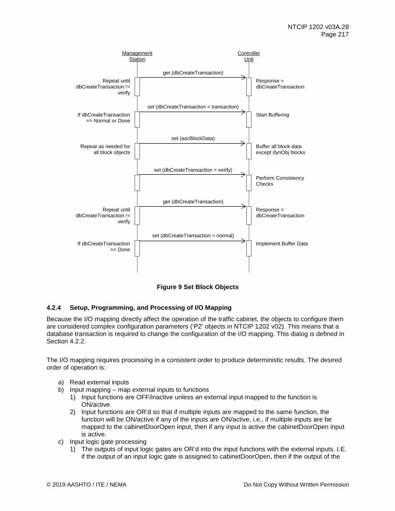
NTCIP 1202 v03A.28 Page 217
© 2019 AASHTO / ITE / NEMA Do Not Copy Without Written Permission
Management Station
Controller Unit
get (dbCreateTransaction)
Repeat until dbCreateTransaction !=
verify
Response = dbCreateTransaction
set (dbCreateTransaction = transaction)
If dbCreateTransaction == Normal or Done
Start Buffering
set (ascBlockData)
Repeat as needed for all block objects
Buffer all block data except dynObj blocks
set (dbCreateTransaction = verify)
Perform Consistency Checks
get (dbCreateTransaction)
Repeat until dbCreateTransaction !=
verify
Response = dbCreateTransaction
set (dbCreateTransaction = normal)
If dbCreateTransaction == Done
Implement Buffer Data
Figure 9 Set Block Objects
4.2.4 Setup, Programming, and Processing of I/O Mapping Because the I/O mapping directly affect the operation of the traffic cabinet, the objects to configure them are considered complex configuration parameters (‘P2’ objects in NTCIP 1202 v02). This means that a database transaction is required to change the configuration of the I/O mapping. This dialog is defined in Section 4.2.2.
The I/O mapping requires processing in a consistent order to produce deterministic results. The desired order of operation is:
a) Read external inputs b) Input mapping – map external inputs to functions
1) Input functions are OFF/inactive unless an external input mapped to the function is ON/active.
2) Input functions are OR’d so that if multiple inputs are mapped to the same function, the function will be ON/active if any of the inputs are ON/active, i.e., if multiple inputs are be mapped to the cabinetDoorOpen input, then if any input is active the cabinetDoorOpen input is active.
c) Input logic gate processing 1) The outputs of input logic gates are OR’d into the input functions with the external inputs. I.E.
if the output of an input logic gate is assigned to cabinetDoorOpen, then if the output of the

NTCIP 1202 v03A.28 Page 218
Do Not Copy Without Written Permission © 2019 AASHTO / ITE / NEMA
logic gate is ON/active then the cabinetDoorOpen function will be ON/active regardless of the status of any external inputs mapped to cabinetDoorOpen.
d) Traffic processing 1) Phases and overlaps are mapped to channels during traffic processing
e) Output logic gate processing f) Output mapping – map functions to external outputs g) Write external outputs h) Generate SPAT information from the outputs
4.2.5 Making an I/O Map Active Making a new I/O map the active map requires a database transaction:
a) Open a database transaction by setting dbCreateTransaction to ‘transaction’ (see the transaction
dialog above) b) Configure the desired I/O map while the dbCreateTransaction is open, or have the desired I/O
map already configured. c) Set ascIOactiveMap to the index of the desired I/O map. d) When all requirements for changing the I/O map set by ascIOactivateRequirement are satisfied,
set dbCreateTransaction to ‘verify.’ e) Get dbCreateTransaction, if equal to ‘done’ then get dbVerifyStatus f) If dbVerifyStatus is ‘doneWithNoError’ then set dbCreateTransaction to ‘normal’. g) Else examine dbVerifyError to determine the cause of the error and make corrections as
necessary.
Once the dbCreateTransaction is successfully completed the new I/O map will be in effect.
4.2.6 Configure Speed Limits for a Node Point The standardized dialog for a management station to configure speed limit information shall be as follows:
a) (Precondition) The management station shall be aware of which row in the tables is to be configured.
b) For the specified row in mapSpeedLimitTable, the management station shall SET the following objects to the desired value:
1) mapSpeedLimitType.x 2) mapSpeedLimit.x
c) For the specified row in mapNodePointTable, the management station shall SET the following object to the desired value.
1) mapNodePointSpeedLimits.y.z
where, x = the index of the speed limit (mapSpeedLimitIndex) y = the index of the lane identifier (mapLaneNumber) z = the index of node point (mapNodePointNumber)
4.2.7 Enable Collection of Connected Data The standardized dialog for a management station to retrieve connected data shall be as follows:
a) (Precondition) The management station shall be aware of which row in the tables is to be configured.
b) The management station shall GET maxCvDetectionZones. c) For the specified row in ascCvDetectorTable, the management station shall SET the following
objects to the desired value: 1) ascCvDetectorOptions.x

NTCIP 1202 v03A.28 Page 219
© 2019 AASHTO / ITE / NEMA Do Not Copy Without Written Permission
2) ascCvDetectorInput.x 3) ascCvDetectorAssignment.x
d) If ascCvDetectorInput.x equals 00, then go to Step g. e) If Bit 2 of ascCvDetectorOptions.x equals 0, the management station shall GET each
mapLaneNumber.y defined in ascCvDetectorInput.x. If the device responds with a noSuchName error, then the mapLaneIndex.y may not be valid, and the management station should exit this process.
f) If Bit 2 of ascCvDetectorOptions.x equals 1, the management station shall GET each detectionZoneNodePointIndex.z defined in ascCvDetectorInput.x. If the device responds with a noSuchName error, then the detectionZoneNodePointIndex.z may not be valid, and the management station should exit this process.
g) The management station shall SET cvDetectionEnable to 1. where, x = the index of the detection zone (ascCvDetectorNumber) y = the index of the lane identifier (mapLaneIndex) z = the index of the detection zone node points (detectionZoneNodePointIndex)
4.2.8 Retrieve Connected Device Detector Zone - Geographic The standardized dialog for a management station to retrieve the geographic boundaries of a detection zone for a connected device detector shall be as follows:
a) (Precondition) The management station shall be aware of which row in the tables is to be configured.
b) The management station shall GET maxCvDetectionZones. c) For the specified row in cvDetectorTable, the management station shall GET
cvDetectorOptions.x. d) For the specified row in cvDetectorTable, the management station shall GET cvDetectorInput.x. e) If Bit 2 of cvDetectorOptions.x is equal to 0, then the management station shall GET
1) mapNodePointX.y,z 2) mapNodePointY.y,z 3) mapNodePointWidth.y,z
Exit this process. f) If cvDetectorInput.x is equal to '00', then there is no geographic boundary defined for this
detection zone, so the management station should exit this process. g) Make y = cvDetectorInput.x. h) The management station shall GET maxDetectionZoneNodePoints i) In detectionZoneNodePointTable, the management station shall GET the following objects:
1) detectionZoneNodePointX.w 2) detectionZoneNodePointY.w 3) detectionZoneNodePointWidth.w 4) detectionZoneNodePointZ.w 5) detectionZoneNodePointHeight.w
where, w = the index of the detection zone node point (detectionZoneNodePointNumber)
x = the index of the detection zone (cvDetectorNumber) y = the index of each lane (mapLaneIndex) defined in cvDetectorInput.x z = the index of the lane path node point (mapNodePointNumber)
4.2.9 Configure Enabled Lanes The standardized dialog for a management station to command the enabled lanes list on an ASC shall be as follows:
NTCIP 1202 v03A.28 Page 220
Do Not Copy Without Written Permission © 2019 AASHTO / ITE / NEMA
a) (Precondition) The management station shall ensure that the selected enabled lanes are configured as revocable lanes in the current MAP plan.
b) The management station shall SET spatEnabledLanesCommand.0 to the desired values. This will cause the ASC to perform a consistency check (See Section 4.3.2) on the command.
c) If the response indicates 'noError', the spatEnabledLanesCommand has taken effect and the management station shall GET the spatPortStatus.x to ensure that there are no errors preventing the command from taking effect. The management station may then exit the process.
d) If the response from Step b indicates an error, the command did not take effect. The management station shall GET spatPortStatus.x to determine the type of error.
where, x = the index of the RSU Port (rsuPortIndex)
4.2.10 Provide Detection Reports to an ASC The standardized dialog for a management station to provide detection reports to an ASC shall be as follows:
a) (Precondition) The management station shall be aware of what detection report (columnar) data is to be exchanged.
b) The management station shall GET activeCvDetectors and detectionReportSequence. c) Make x = the value of detectionReportSequence. d) For the specified row in detectionReportTable, the management station shall SET
AscCvDetectionReportBlockData in accordance with Section 4.2.3. Only the columnar data requested, as configured in detectionReportCollection, shall be sent in AscCvDetectionReportBlockData. If the columnar data is NOT sent, that columnar data shall be SET to the default value.
e) The ASC shall increment detectionReportSequence. where, x = the index of the detection report number (detectionReportSequence)
4.2.11 Activating a MAP Plan The standardized dialog for a management station to command the CV Roadside Process to activate a MAP plan to be broadcasted shall be as follows:
a) (Precondition) The management station shall ensure that the desired MAP plan is supported by the CV Roadside Process. This may entail downloading the desired MAP plan contents to the CV Roadside Process.
b) The management station shall SET mapActivatePlan.0 to the desired value. Note: mapActivatePlan.0 is a structure that contains the map plan number (mapPlanIndex) and a CRC of the map plan contents.
c) If the response indicates 'noError,' the MAP plan has been activated, and the management station shall GET mapActivatePlanError.0 to ensure that there are no errors preventing the broadcast of the MAP plan contents. The management station may then exit the process.
d) If the response from Step c indicates an error, the MAP plan was not activated. The management station shall GET mapActivatePlanError.0 to determine the type of error.
4.2.12 Confirm MAP Compatibility The standardized dialog for an ASC to confirm the SPAT data generated is compatible with the MAP plan broadcasted by the CV Roadside Process is as follows:

NTCIP 1202 v03A.28 Page 221
© 2019 AASHTO / ITE / NEMA Do Not Copy Without Written Permission
a) (Precondition) A management station shall SET the spatPortMapActivationCode for each CV Roadside Process that the ASC is to exchange SPAT data with.
b) (Precondition) If the CV Roadside Process is the SNMP manager for the ASC Process - CV Roadside Process interface, the CV Roadside Process shall SET mapActivatePlan.0 on the ASC.
c) If the ASC is the SNMP manager, the ASC shall GET the mapActivatePlan.0 from the appropriate CV Roadside Process.
d) The ASC shall compare the mapActivatePlan.0 with spatPortMapActivationCode.x. If the values match, then the ASC may exit the process.
e) If the values do not match, spatPortStatus.x shall be mapError(4), and the ASC shall stop providing SPAT data to this CV Roadside Process.
f) If the response from Step c indicates an error, the MAP plan was not activated. The management station shall GET mapActivatePlanError.0 to determine the type of error.
where, x = the index of the RSU port (rsuPortIndex)
4.3 State-Transition Diagrams State-Transition diagrams are included for those objects that have states or manage states. The State Transition Diagrams include state-transition tables (listing of the possible state transitions), legitimate transitions, and any illegitimate transitions. "State-transition diagrams describe all of the states that an object can have, the events under which an object changes state (transitions), the conditions that must be fulfilled before the transition will occur (guards), and the activities undertaken during the life of an object (actions)." (Reference: State-Transition Diagrams: Testing UML Models, Part 4 by Lee Copeland) The objects for an ASC device do not have states or manage states, but are classified by data parameter type, as defined in Section 4.3.1. For those objects that are defined as a 'critical' data parameter type, the consistency checks defined in Section 4.3.2 are required to be performed. Section 4.3.3 describes the behavior of the device when a non-sequential time change is detected.
4.3.1 Data Parameter Types An ASC shall support different types of parameters, which are either:
a) pure status/information parameters (called ‘S’ objects in earlier versions of NTCIP 1202), b) simple configuration parameters (called ‘P’ or ‘C’ objects in earlier versions of NTCIP 1202), or c) critical configuration parameters that the ASC has to evaluate for consistency before it will use
them (called ‘P2’ objects in earlier versions of NTCIP 1202). All parameters can be retrieved using simple SNMP GET commands. Pure status/information ('S' objects) parameters are read-only objects, therefore, an SNMP SET command is not permitted on these types of parameters. These types of parameters may also be contained in block objects (see Section 6) or in dynamic objects (see Annex H.1.1.9). Simple configuration parameters ('C' or 'P' objects) can be configured using a simple SNMP SET command. However, the use of 'dbCreateTransaction' in NTCIP 1201 v03 Section 2.3.1 shall NOT delay an SNMP SET to 'C' objects, while the use of 'dbCreateTransaction' in NTCIP 1201 v03 Section 2.3.1 for 'P' objects is optional. The device also has to support both the normal SNMP SET and a SET via dbCreateTransaction for 'P' objects. Simple configuration parameters may be contained within block objects (see Section 6) or in dynamic objects (see Annex H.1.1.9). Critical configuration parameters or any settable objects defined within Block Objects shall not be configured using a simple SNMP SET command, but instead shall be configured using a special data

NTCIP 1202 v03A.28 Page 222
Do Not Copy Without Written Permission © 2019 AASHTO / ITE / NEMA
exchange mechanism. This data exchange mechanism is defined above in Section 4.2.3 and in NTCIP 1201 v03 Sections 2.3 and Annex A.1. It is basically a mechanism to open the database in which the new configuration values are to be stored, to download those new configuration values, to close the database, and to instruct the controller to verify the new downloaded values in conjunction with other values stored in the database (this process is referred to as ‘dbCreateTransaction’ and the verification process is referred to as ‘consistency checks’ – see Section 4.3.2). Only once this process has been completed successfully will the ASC use the downloaded configuration parameter values.
4.3.2 Consistency Checks Consistency checks assure that certain critical objects are checked “in context” and treated as interrelated values rather than separate non-related data items. When data is downloaded to an ASC operating in the “transaction” mode, as defined by the dbCreateTransaction object defined in NTCIP 1201 v03, consistency checks shall be performed on downloaded data when the “verify” state of the ‘dbCreateTransaction’ object is commanded. The consistency checks that shall occur and corresponding error messages are described below. Error messages, if any, may be examined by reading the 'dbTransactionError' object defined in NTCIP 1201 v03 once the ASC has entered the “done” mode of the ‘dbCreateTransaction’ object.
4.3.2.1 Consistency Check Rules The consistency check rule is stated first, followed by the corresponding error message(s).
• Concurrent Phases, as defined by the phaseConcurrency object, must be in a different ring from phaseNumber (assuming that the phase contained in the phaseNumber object is defined). The error message indicates one or more defined concurrent phases have the same ring assignment as phaseNumber. The value “xx” corresponds to phaseNumber.
“PHASE xx CONCURRENCY FAULT” An example: phaseConcurrency.1 (Phase 1 concurrent phases) includes Phase 2 and phaseRing.1 (Phase 1 Ring) equals phaseRing.2 (Phase 2 Ring). An error message of "PHASE 01 CONCURRENCY FAULT" within the ‘dbTransactionError’ object is generated.
• Concurrent Phases, as defined by the phaseConcurrency object, must be mutually concurrent
with phaseNumber (assuming that the phase contained in the phaseNumber object is defined). The error message indicates one or more defined concurrent phases does not include phaseNumber as a concurrent phase. The value "xx" corresponds to phaseNumber. "PHASE xx MUTUAL FAULT" An example: phaseConcurrency.1 (Phase 1 concurrent phases) includes phase 5, and phaseConcurrency.5 (Phase 5 concurrent phases) does not include phase 1. An error message of "PHASE 01 MUTUAL FAULT" is provided.
• Phase Sequences, as defined by the sequenceData object, must include phases only once in a given phase sequence. The error message indicates a phase appears more than once in a phase sequence. The value “xx” corresponds to sequenceNumber for sequenceData. “SEQ xx SAME PHASE FAULT” An example: sequenceData.1.1 (Sequence 01 / Ring 1) is 01-02-03-04-01 (Phase 1 appears twice). An error message of "SEQ 01 SAME PHASE FAULT" is provided.
• Phase Sequences, as defined by the sequenceData object, must include only phases with a ring assignment (phaseRing) equal to sequenceRingNumber. The error message indicates a phase

NTCIP 1202 v03A.28 Page 223
© 2019 AASHTO / ITE / NEMA Do Not Copy Without Written Permission
defined by sequenceData does not have a phaseRing equal to sequenceRingNumber. The value “xx” corresponds to sequenceNumber. The value "#" corresponds to sequenceRingNumber. “SEQ xx RING # FAULT” An example: sequenceData.1.1 (Sequence 01 / Ring 1) is 01-02-03-04-05 and all phaseRing parameters = 1 except phaseRing.5 = 2. An error message of "SEQ 01 RING 1 FAULT" is provided.
• Phase Sequences, as defined by the sequenceData object, must include all phases with a ring assignment (phaseRing) equal to sequenceRingNumber. The error message indicates a phase has been omitted in the sequenceData for sequenceRingNumber. The value “xx” corresponds to sequenceNumber. The value "#" corresponds to sequenceRingNumber. “SEQ xx RING # PHS OMITTED” A standard dual ring example: sequenceData.1.1 (Sequence 01 / Ring 1) is 01-02-03 (does not include Phase 4). An error message of "SEQ 01 RING 1 PHS OMITTED" is provided.
• Phase Sequences, as defined by the sequenceData object, must be ordered such that all sequenceRingNumber phases within a Concurrency Group can be serviced sequentially without leaving the Concurrency Group of which they are a member. The error message indicates all phases in a Concurrency Group could not be serviced sequentially. The value “xx” corresponds to sequenceNumber. “SEQ xx RING SEQ FAULT” An standard dual ring example: sequenceData.1.1 (Sequence 01 / Ring 1) is 01-03-02-04 and sequenceData.1.2 (Sequence 01 / Ring 2) is 05-06-07-08. An error message of "SEQ 01 RING SEQ FAULT" is provided.
• Phase Sequences, as defined by the sequenceData object; phases must be arranged, so Concurrency Groups of which phases are a member are sequenced in the same order in all rings for a given sequenceNumber. The error message indicates Concurrency Groups are not in the same order for all. The value “xx” corresponds to sequenceNumber. “SEQ xx CG SEQ FAULT” An standard dual ring example: sequenceData.1.1 (Sequence 01 / Ring 1) is 01-02-03-04 and sequenceData.1.2 (Sequence 01 / Ring 2) is 07-08-05-06. An error message of "SEQ 01 RING SEQ FAULT" is provided.
• Phase Sequences, as defined by the sequenceData object; phases must be arranged so that it is possible to service all phases (not skip any phase due to compatibility constraints) in all rings in the order defined. "SEQ xx SEQUENCING FAULT" An example (lead-lag dual ring where phase 1 & 5 cannot operate concurrently): sequenceData.1.1 (Sequence 01 / Ring 1) is 02-01-03-04 and sequenceData.1.2 (Sequence 01 / Ring 2) is 06-05-07-08. An error message of "SEQ 01 SEQUENCING FAULT" is provided.
• Phase Sequences, as defined by the sequenceData object: all sequences must contain entries for all active rings.
NTCIP 1202 v03A.28 Page 224
Do Not Copy Without Written Permission © 2019 AASHTO / ITE / NEMA
" SEQ xx RING xx EMPTY" " SEQ xx ALL RINGS EMPTY"
• The following objects define functionality related to phase assignments. Consistency checks among other things insure that phases specified by these objects may operate concurrently and are defined only once in each string parameter. Note that if the objects are not defined, operation between different CU’s may be inconsistent.
Phase Startup (phaseStartup) Automatic Flash Entry Phases (phaseOptions[1]) Automatic Flash Exit Phases (phaseOptions[2]) Overlap Included Phases (overlapIncludedPhases) Overlap Modifier Phases (overlapModifierPhases) Preempt Track Clear Phases (preemptTrackPhase) Preempt Dwell Phases (preemptDwellPhase) Preempt Dwell Peds (preemptDwellPed) Preempt Exit Phases (preemptExitPhase) Preempt Cycling Phases (preemptCyclingPhase) Preempt Cycling Ped (preemptCyclingPed) When the defined phases CAN NOT time concurrently:
“START PHASE CG FAULT” “FLASH ENTRY CG FAULT” “FLASH EXIT CG FAULT” “PE TRACK PHASE CG FAULT” “PE DWELL PHASE CG FAULT” “PE EXIT PHASE CG FAULT”
When the defined phases are in the same ring:
“START PHASE RING FAULT” “FLASH ENTRY RING FAULT” “FLASH EXIT RING FAULT” “PE TRACK PHASE RING FAULT” “PE DWELL PHASE RING FAULT” “PE EXIT PHASE RING FAULT”
When the defined phases are in the string parameter more than once:
“OVLP INC PHASE MULTI FAULT” “OVLP MOD PHASE MULTI FAULT” “PE TRACK PHASE MULTI FAULT” “PE DWELL PHASE MULTI FAULT” “PE DWELL PED MULTI FAULT” “PE EXIT PHASE MULTI FAULT” “PE CYCLING PHASE MULTI FAULT” “PE CYCLING PED MULTI FAULT” “PHASE xx CONCURRENCY PHASE MULTI FAULT”
When a defined phase is disabled.
“START PHASE DISABLE FAULT” “FLASH ENTRY DISABLE FAULT” “FLASH EXIT DISABLE FAULT” "PE TRACK PHASE DISABLE FAULT" “PE DWELL PHASE DISABLE FAULT” “PE EXIT PHASE DISABLE FAULT”

NTCIP 1202 v03A.28 Page 225
© 2019 AASHTO / ITE / NEMA Do Not Copy Without Written Permission
When a peds parent phase is NOT active. “PE DWELL PED PARENT FAULT” “PHASE XX CONCURRENCY PHASE DISABLE FAULT” “SEQ XX RING X PHASE DISABLE FAULT”
When a peds parent phase is NOT active.
“PE DWELL PED PARENT FAULT” When the defined phases contain an invalid phase number value:
“PHASE xx CONCURRENCY PHASE NUM FAULT” “SEQ xx RING xx PHASE NUM FAULT” “START PHASE xx BAD VALUE FAULT”
• The following objects define functionality related to overlap assignments. Consistency checks insure that overlaps specified by these objects may only be active when an included phase (overlapIncludedPhases) is active. Preempt Track Clear Overlaps (preemptTrackOverlap) Preempt Dwell Overlaps (preemptDwellOverlap) Preempt Cycling Overlap (preemptCyclingOverlap) When an included phase IS NOT defined to be active:
“PE TRACK OVERLAP FAULT” “PE DWELL OVERLAP FAULT”
When the defined overlaps are in the string parameter more than once:
“PE TRACK OVLP MULTI FAULT” “PE DWELL OVLP MULTI FAULT” “PE CYCLING OVLP MULTI FAULT”
• The following objects define functionality related to coordination patterns. Consistency checks
insure that patterns specified by these objects is active. Pattern Cycle Length (patternCycleTime) Pattern Offset Time (patternOffsetTime) Pattern Split Phase (splitPhase) Pattern Split Time (splitTime) Pattern Split Coordinated Phase (splitCoordPhase) When the sum of phase minimum times exceeds the cycle length:
“PATTERN xx PHASE MINS EXCEED CYCLE”
When the sum of the split times exceeds the cycle length: “PATTERN xx SPLITS EXCEED CYCLE”
When the pattern offset exceeds the cycle length: “PATTERN xx OFFSET EXCEEDS CYCLE”
When the splits of a ring have no indicated coordinated phase: “PATTERN xx RING xx HAS NO SYNC PHASE”
When the minimum time of a phase exceeds its split time: “PATTERN xx PHASE xx MIN EXCEEDS SPLIT”
• When no consistency faults are detected in the data when leaving “transaction” mode, the following shall be written to the dbVerifyError object:

NTCIP 1202 v03A.28 Page 226
Do Not Copy Without Written Permission © 2019 AASHTO / ITE / NEMA
“NO VERIFICATION ERROR”
Note that the order of the checks is not defined. Therefore, for a given set of 'bad' data, the Error Message between different ASC’s may be inconsistent.
• The following objects define functionality related to I/O mapping. Consistency checks insure that the input and output mappings contain valid functions and indexes: I/O Map input / output index (ascIOinputMapIOindex, ascIOoutputMapIOindex) I/O Map input / output function (ascIOinputMapFunction, ascIOoutputMapFunction) I/O Map input / output function index (ascIOinputMapFuncIndex, ascIOoutputMapFuncIndex) “FIO INPUT MAP ROW xx INVALID FCTN” “FIO INPUT MAP ROW xx INVALID INDX” “FIO OUTPUT MAP ROW xx INVALID FCTN” “FIO OUTPUT MAP ROW xx INVALID INDX” “TS1 INPUT MAP ROW xx INVALID FCTN” “TS1 INPUT MAP ROW xx INVALID INDX” “TS1 OUTPUT MAP ROW xx INVALID FCTN” “TS1 OUTPUT MAP ROW xx INVALID INDX” “BIU xx INPUT MAP ROW xx INVALID FCTN” “BIU xx INPUT MAP ROW xx INVALID INDX” “BIU xx OUTPUT MAP ROW xx INVALID FCTN” “BIU xx OUTPUT MAP ROW xx INVALID INDX” “SIU xx INPUT MAP ROW xx INVALID FCTN” “SIU xx INPUT MAP ROW xx INVALID INDX” “SIU xx OUTPUT MAP ROW xx INVALID FCTN” “SIU xx OUTPUT MAP ROW xx INVALID INDX” “AUX INPUT MAP INVALID FCTN” “AUX INPUT MAP INVALID INDX”
• Concurrent Enabled Lanes, as defined by the enabledLaneConcurrency object, has to be concurrent with the other Enabled lanes that are being defined as ACTIVE (spatEnabledLanesCommand or patternSpatEnabledLanes). The error message indicates one or more defined ACTIVE Enabled lanes does not include the Enabled lane (enabledLaneIndex for spatEnabledLanesCommand or mapLaneIndex for patternSpatEnabledLanes) as a concurrent Enabled lane. The value "xx" corresponds to the enabledLaneIndex or mapLaneIndex.
"ENABLED LANE xx CONCURRENCY FAULT"
An example: patternSpatEnabledLanes.1 (System pattern 1) includes mapLaneIndex 5 (05) and 6 (06), but enabledLaneIndex.5 does not include mapLaneIndex 6 (06). An error message of ENABLED LANE 05 CONCURRENCY FAULT is provided.
• A MAP lane, as referenced by the object mapComputedLaneReference, has to be defined by at least two valid node points in the mapNodePointTable. The error message indicates that the referenced MAP lane (mapLaneIndex) for a computed lane does not have at least two valid node points. The value "xx" corresponds to the mapLaneIndex.
"MAPLANEINDEX xx REFERENCED COMPUTED LANE FAULT"
An example: mapComputedLaneReference.5 has a value of 4, but mapNodePointX.4.1 (mapLaneIndex 4 / mapNodePointNumber 1) has a value of 1800000001 and mapNodePointY.4.1 has a value of 900000001, of which both values are equivalent to unknown. An error message of "MAPLANEINDEX 04 REFERENCED COMPUTED LANE FAULT" is provided.

NTCIP 1202 v03A.28 Page 227
© 2019 AASHTO / ITE / NEMA Do Not Copy Without Written Permission
• A MAP lane, as referenced by the object cvDetectorInput if Bit 2 = 0 in the cvDetectorOptions object, has to be defined by at least two valid node points in the mapNodePointTable. The error message indicates that the referenced MAP lane (mapLaneIndex) for a computed lane does not have at least two valid node points. The value "xx" corresponds to the mapLaneIndex.
"MAPLANEINDEX xx CV DETECTOR FAULT"
An example: cvDetectorInput.3 has a value of 05, but mapNodePointX.5.1 (mapLaneIndex 5 / mapNodePointNumber 1) has a value of 1800000001 and mapNodePointY.5.1 has a value of 900000001, of which both values are equivalent to unknown. An error message of "MAPLANEINDEX 05 CV DETECTOR FAULT" is provided.
4.3.3 Non-Sequential Time Change The standardized dialog for a device to log a non-sequential change to the ASC clock time shall be as follows:
a) (Precondition) The device shall be aware of which row in the eventLogTable is the new event to be recorded
b) The device receives a non-sequential change to the unit (device) time. c) The device shall update the device globalTime. d) The device shall add an event to the event log with the following data, where eventLogTime is
equal to the device globalTime: 1) eventLogID.x.y 2) eventLogTime.x.y 3) eventLogValue.x.y 4) eventLogTimeMilliseconds.x.y (if supported)
e) The device shall add an event to the event log with the value of unitTimeNonSequentialSource, unitTimeNonSequentialChange, and unitTimeNonSequentialDelta.
Where: x = event log class y = event log number

NTCIP 1202 v03A.28 Page 228
Copy Per MIB Distribution Permission © 2019 AASHTO / ITE / NEMA
Section 5 Management Information Base (MIB) [Normative]
Section 5 defines those objects that are specifically used by Actuated Signal Controllers (ASC). The objects are defined using the OBJECT-TYPE macro as specified in RFC 1212 and NTCIP 8004 v02. The text provided from Section 5 through the end of Section 6 (except the section headings) constitutes the standard NTCIP1202-v03 MIB. All of the objects defined in this NTCIP 1202 v03 reside under the “asc” node of the global naming tree. To aid in object management, the “asc” node has been subdivided into logical categories, each defined by a node under the “asc” node. The individual objects are then located under the appropriate node. Conformance requirements for any object is determined by the use of the Requirements Traceability Matrix (RTM) in Annex A. To support any defined Requirement, an implementation shall support all objects to which the Requirement traces in the RTM. The value of the STATUS field for every object in the MIB is "mandatory," and indicates that it is mandatory if any associated Requirement is selected. For all bitmapped objects, if a bit is zero (0), then the referenced function is disabled or not supported, and if a bit is one (1), then the referenced function is enabled or supported. A computer readable format of this information, called a Management Information Base, is available from NEMA ([email protected]). The MIB has been verified using SMICng Version 2.2.07 (Book). Previous versions of NTCIP 1202 v03 defined data elements that have been replaced to resolve ambiguities; however, central systems may need to interoperate with older equipment and support such data elements. Annex D documents the reason that the ASC WG decided to deprecate various objects.
5.0 MIB Comment Header --********************************************************************* -- Filename: 1202v0328.MIB -- Date: May 30, 2019 -- Description: This MIB defines the Actuated Signal Controller -- Objects --*********************************************************************
5.1 MIB Header NTCIP1202-v03 DEFINITIONS ::= BEGIN -- the following OBJECT IDENTIFIERS are used in the ASC MIB: IMPORTS IpAddress, Counter, null
FROM RFC1155-SMI OBJECT-TYPE
FROM RFC-1212 DisplayString, ifIndex FROM RFC1213-MIB
OwnerString, OerString, devices FROM NTCIP8004v02;

NTCIP 1202 v03A.28 Page 229
© 2019 AASHTO / ITE / NEMA Copy Per MIB Distribution Permission
asc OBJECT IDENTIFIER ::= { devices 1 }
5.2 Phase Parameters phase OBJECT IDENTIFIER ::= { asc 1 } -- This node shall contain objects that configure, monitor or -- control phase functions for this device.
5.2.1 Maximum Phases maxPhases OBJECT-TYPE
SYNTAX INTEGER (2..255) ACCESS read-only STATUS mandatory DESCRIPTION "<Definition> The Maximum Number of Phases this Controller
Unit supports. This object indicates the maximum rows which shall appear in the phaseTable object.
<Object Identifier> 1.3.6.1.4.1.1206.4.2.1.1.1 <Unit> phase"
::= { phase 1 }
5.2.2 Phase Table phaseTable OBJECT-TYPE
SYNTAX SEQUENCE OF PhaseEntry ACCESS not-accessible STATUS mandatory DESCRIPTION "<Definition> A table containing Controller Unit phase
parameters. The number of rows in this table is equal to the maxPhases object.
<TableType> static <Object Identifier> 1.3.6.1.4.1.1206.4.2.1.1.2"
::= { phase 2 } phaseEntry OBJECT-TYPE
SYNTAX PhaseEntry ACCESS not-accessible STATUS mandatory DESCRIPTION "<Definition> Parameters for a specific Controller Unit
phase. <Object Identifier> 1.3.6.1.4.1.1206.4.2.1.1.2.1 <Unit> " INDEX { phaseNumber }
::= { phaseTable 1 } PhaseEntry ::= SEQUENCE {
phaseNumber INTEGER, phaseWalk INTEGER, phasePedestrianClear INTEGER, phaseMinimumGreen INTEGER, phasePassage INTEGER, phaseMaximum1 INTEGER, phaseMaximum2 INTEGER, phaseYellowChange INTEGER,

NTCIP 1202 v03A.28 Page 230
Copy Per MIB Distribution Permission © 2019 AASHTO / ITE / NEMA
phaseRedClear INTEGER, phaseRedRevert INTEGER, phaseAddedInitial INTEGER, phaseMaximumInitial INTEGER, phaseTimeBeforeReduction INTEGER, phaseCarsBeforeReduction INTEGER, phaseTimeToReduce INTEGER, phaseReduceBy INTEGER, phaseMinimumGap INTEGER, phaseDynamicMaxLimit INTEGER, phaseDynamicMaxStep INTEGER, phaseStartup INTEGER, phaseOptions INTEGER, phaseRing INTEGER, phaseConcurrency OCTET STRING, phaseMaximum3 INTEGER, phaseYellowandRedChangeTimeBeforeEndPedClear INTEGER, phasePedWalkService INTEGER, phaseDontWalkRevert INTEGER, phasePedAlternateClearance INTEGER, phasePedAlternateWalk INTEGER, phasePedAdvanceWalkTime INTEGER, phasePedDelayTime INTEGER, phaseAdvWarnGrnStartTime INTEGER, phaseAdvWarnRedStartTime INTEGER, phaseAltMinTimeTransition INTEGER }
5.2.2.1 Phase Number phaseNumber OBJECT-TYPE
SYNTAX INTEGER (1..255) ACCESS read-only STATUS mandatory DESCRIPTION "<Definition> The phase number for objects in this row.
This value shall not exceed the maxPhases object value. <Object Identifier> 1.3.6.1.4.1.1206.4.2.1.1.2.1.1 <Unit> phase"
::= { phaseEntry 1 }
5.2.2.2 Phase Walk Parameter phaseWalk OBJECT-TYPE
SYNTAX INTEGER (0..255) ACCESS read-write STATUS mandatory DESCRIPTION "<Definition> Phase Walk Parameter in seconds. This shall
control the amount of time the Walk indication shall be displayed. This parameter shall be used regardless whether the pedestrian indication associated with this phase is for a ped-only phase or for a pedestrian indication that runs parallel to a vehicle phase.
<Object Identifier> 1.3.6.1.4.1.1206.4.2.1.1.2.1.2 <Unit> second" REFERENCE "NEMA TS 2 Clause 3.5.3.1 and 3.5.3.2.2.a"
::= { phaseEntry 2 }

NTCIP 1202 v03A.28 Page 231
© 2019 AASHTO / ITE / NEMA Copy Per MIB Distribution Permission
5.2.2.3 Phase Pedestrian Clear Parameter phasePedestrianClear OBJECT-TYPE
SYNTAX INTEGER (0..255) ACCESS read-write STATUS mandatory DESCRIPTION "<Definition> Phase Pedestrian Clear Parameter in seconds.
This shall control the duration of the Pedestrian Clearance output (if present) and the flashing period of the Don’t Walk output. This parameter shall be used regardless whether the pedestrian indication associated with this phase is for a ped-only phase or for a pedestrian indication that runs parallel to a vehicle phase.
<Object Identifier> 1.3.6.1.4.1.1206.4.2.1.1.2.1.3 <Unit> second" REFERENCE "NEMA TS 2 Clause 3.5.3.1 and 3.5.3.2.2.b"
::= { phaseEntry 3 }
5.2.2.4 Phase Minimum Green Parameter phaseMinimumGreen OBJECT-TYPE
SYNTAX INTEGER (0..255) ACCESS read-write STATUS mandatory DESCRIPTION "<Definition> Phase Minimum Green Parameter in seconds
(NEMA TS 2 range: 1-255 sec). The first timed portion of the Green interval which may be set in consideration of the storage of vehicles between the zone of detection for the approach vehicle detector(s) and the stop line.
<Object Identifier> 1.3.6.1.4.1.1206.4.2.1.1.2.1.4 <Unit> second" REFERENCE "NEMA TS 2 Clause 3.5.3.1 and 3.5.3.2.1.a.(1)"
::= { phaseEntry 4 }
5.2.2.5 Phase Passage Parameter phasePassage OBJECT-TYPE
SYNTAX INTEGER (0..255) ACCESS read-write STATUS mandatory DESCRIPTION "<Definition> Phase Passage Parameter in tenth seconds (0-
25.5 sec). Passage Time, Vehicle Interval, Preset Gap, Vehicle Extension: the extensible portion of the Green shall be a function of vehicle actuations that occur during the Green interval. The phase shall remain in the extensible portion of the Green interval as long as the passage timer is not timed out. The timing of this portion of the green interval shall be reset with each subsequent vehicle actuation and shall not commence to time again until the vehicle actuation is removed or the maximum green timer has expired.
<Object Identifier> 1.3.6.1.4.1.1206.4.2.1.1.2.1.5 <Unit> tenth second" REFERENCE "NEMA TS 2 Clause 3.5.3.1 and 3.5.3.2.1.a.(2)"
::= { phaseEntry 5 }

NTCIP 1202 v03A.28 Page 232
Copy Per MIB Distribution Permission © 2019 AASHTO / ITE / NEMA
5.2.2.6 Phase Maximum Green 1 Parameter phaseMaximum1 OBJECT-TYPE
SYNTAX INTEGER (0..255) ACCESS read-write STATUS mandatory DESCRIPTION "<Definition> Phase Maximum 1 Parameter in seconds (NEMA TS
2 range: 1-255 sec). This time setting shall determine the maximum length of time this phase may be held in Green in the presence of a serviceable conflicting call. In the absence of a serviceable conflicting call the Maximum Green timer shall be held reset unless Max Vehicle Recall is enabled for this phase. This is the default maximum value to use. It may be overridden via an external input, coordMaximumMode or other method.
<Object Identifier> 1.3.6.1.4.1.1206.4.2.1.1.2.1.6 <Unit> second" REFERENCE "NEMA TS 2 Clause 3.5.3.1, 3.5.3.2.1.a.(3) and 3.5.3.5"
::= { phaseEntry 6 }
5.2.2.7 Phase Maximum Green 2 Parameter phaseMaximum2 OBJECT-TYPE
SYNTAX INTEGER (0..255) ACCESS read-write STATUS mandatory DESCRIPTION "<Definition> Phase Maximum 2 Parameter in seconds (NEMA TS
2 range: 1-255 sec). This time setting shall determine the maximum length of time this phase may be held in Green in the presence of a serviceable conflicting call. In the absence of a serviceable conflicting call the Maximum Green timer shall be held reset unless Max Vehicle Recall is enabled for this phase. This may be implemented as the max green timer via an external input, coordMaximumMode or other method.
<Object Identifier> 1.3.6.1.4.1.1206.4.2.1.1.2.1.7 <Unit> second" REFERENCE "NEMA TS 2 Clause 3.5.3.1, 3.5.3.2.1.a.(3), 3.5.3.5 and 3.5.4.1 (7)"
::= { phaseEntry 7 }
5.2.2.8 Phase Yellow Change Parameter phaseYellowChange OBJECT-TYPE
SYNTAX INTEGER (0..255) ACCESS read-write STATUS mandatory DESCRIPTION "<Definition> Phase Yellow Change Parameter in tenth
seconds (NEMA TS 2 range: 3-25.5 sec). Following the Green interval of each phase the CU shall provide a Yellow Change interval which is timed according to the Yellow Change parameter for that phase.
<Object Identifier> 1.3.6.1.4.1.1206.4.2.1.1.2.1.8 <Unit> tenth second" REFERENCE "NEMA TS 2 Clause 3.5.3.1 and 3.5.3.2.5.a"
::= { phaseEntry 8 }
NTCIP 1202 v03A.28 Page 233
© 2019 AASHTO / ITE / NEMA Copy Per MIB Distribution Permission
5.2.2.9 Phase Red Clear Parameter phaseRedClear OBJECT-TYPE
SYNTAX INTEGER (0..255) ACCESS read-write STATUS mandatory DESCRIPTION "<Definition> Phase Red Clearance Parameter in tenth
seconds (0-25.5 sec).Following the Yellow Change interval for each phase, the CU shall provide a Red Clearance interval which is timed according to the Red Clearance parameter for that phase.
<Object Identifier> 1.3.6.1.4.1.1206.4.2.1.1.2.1.9 <Unit> tenth second" REFERENCE "NEMA TS 2 Clause 3.5.3.1 and 3.5.3.2.5.b"
::= { phaseEntry 9 }
5.2.2.10 Phase Red Revert phaseRedRevert OBJECT-TYPE
SYNTAX INTEGER (0..255) ACCESS read-write STATUS mandatory DESCRIPTION "<Definition> Red revert time parameter in tenth seconds. A
minimum Red indication to be timed following the Yellow Change interval and prior to the next display of Green on the same signal output driver group. The unitRedRevert parameter shall act as a minimum red revert time for all signal displays. The phaseRedRevert parameter may increase the red revert time for a specific phase. If the phaseRedRevert parameter is less than the unitRedRevert the unitRedRevert time shall be used.
<Object Identifier> 1.3.6.1.4.1.1206.4.2.1.1.2.1.10 <Unit> tenth second"
::= { phaseEntry 10 }
5.2.2.11 Phase Added Initial Parameter phaseAddedInitial OBJECT-TYPE
SYNTAX INTEGER (0..255) ACCESS read-write STATUS mandatory DESCRIPTION "<Definition> Phase Added Initial Parameter in tenths of
seconds (0-25.5 sec). Added Initial parameter (Seconds / Actuation) shall determine the time by which the variable initial time period will be increased from zero with each vehicle actuation received during the associated phase Yellow and Red intervals.
<Object Identifier> 1.3.6.1.4.1.1206.4.2.1.1.2.1.11 <Unit> tenth second" REFERENCE "NEMA TS 2 Clause 3.5.3.1 and 3.5.3.2.1.b.(1).(b)"
::= { phaseEntry 11 }
5.2.2.12 Phase Maximum Initial Parameter phaseMaximumInitial OBJECT-TYPE
SYNTAX INTEGER (0..255) ACCESS read-write STATUS mandatory

NTCIP 1202 v03A.28 Page 234
Copy Per MIB Distribution Permission © 2019 AASHTO / ITE / NEMA
DESCRIPTION "<Definition> Phase Maximum Initial Parameter in seconds (0-255 sec). The maximum value of the variable initial timing period. Variable Initial timing shall equal the lesser of [added initial (seconds / actuation) * number of actuations] or [ Max Initial ]. The variable initial time shall not be less than Minimum Green.
<Object Identifier> 1.3.6.1.4.1.1206.4.2.1.1.2.1.12 <Unit> second" REFERENCE "NEMA TS 2 Clause 3.5.3.2.1.b.(1).(c)"
::= { phaseEntry 12 }
5.2.2.13 Phase Time Before Reduction Parameter phaseTimeBeforeReduction OBJECT-TYPE
SYNTAX INTEGER (0..255) ACCESS read-write STATUS mandatory DESCRIPTION "<Definition> Phase Time Before Reduction (TBR) Parameter
in seconds (0-255 sec). The Time Before Reduction period shall begin when the phase is Green and there is a serviceable conflicting call. If the serviceable conflicting call is removed before completion of this time (or time to reduce), the timer shall reset. Upon completion of the TBR period or the CarsBeforeReduction (CBR) parameter is satisfied, whichever occurs first, the linear reduction of the allowable gap from the Passage Time shall begin.
<Object Identifier> 1.3.6.1.4.1.1206.4.2.1.1.2.1.13 <Unit> second" REFERENCE "NEMA TS 2 Clause 3.5.3.1 and 3.5.3.2.1.b.(2)"
::= { phaseEntry 13 }
5.2.2.14 Phase Cars Before Reduction Parameter phaseCarsBeforeReduction OBJECT-TYPE
SYNTAX INTEGER (0..255) ACCESS read-write STATUS mandatory DESCRIPTION "<Definition> Phase Cars Before Reduction (CBR) Parameter
(0-255 vehicles). When the phase is Green and the sum of the cars waiting (vehicle actuations during Yellow & Red intervals) on serviceable conflicting phases equals or exceeds the CBR parameter or the Time Before Reduction (TBR) parameter is satisfied, whichever occurs first, the linear reduction of the allowable gap from the Passage Time shall begin.
<Object Identifier> 1.3.6.1.4.1.1206.4.2.1.1.2.1.14 <Unit> vehicle"
::= { phaseEntry 14 }
5.2.2.15 Phase Time To Reduce Parameter phaseTimeToReduce OBJECT-TYPE
SYNTAX INTEGER (0..255) ACCESS read-write STATUS mandatory DESCRIPTION "<Definition> Phase Time To Reduce Parameter in seconds (0-
255 sec). This parameter shall control the rate of reduction of

NTCIP 1202 v03A.28 Page 235
© 2019 AASHTO / ITE / NEMA Copy Per MIB Distribution Permission
the allowable gap between the Passage Time and Minimum Gap setting.
<Object Identifier> 1.3.6.1.4.1.1206.4.2.1.1.2.1.15 <Unit> second" REFERENCE "NEMA TS 2 Clause 3.5.3.1 and 3.5.3.2.1.b.(2)"
::= { phaseEntry 15 }
5.2.2.16 Phase Reduce By phaseReduceBy OBJECT-TYPE
SYNTAX INTEGER (0..255) ACCESS read-write STATUS mandatory DESCRIPTION "<Definition> This object may be used for volume density
gap reduction as an alternate to the linear reduction defined by NEMA TS 1 and TS 2. It contains the tenths of seconds to reduce the gap by (0.0 - 25.5 seconds). The frequency of reduction shall produce the Minimum Gap after a time equal to the ‘phaseTimeToReduce’ object.
<Object Identifier> 1.3.6.1.4.1.1206.4.2.1.1.2.1.16 <Unit> tenth second"
::= { phaseEntry 16 }
5.2.2.17 Phase Minimum Gap Parameter phaseMinimumGap OBJECT-TYPE
SYNTAX INTEGER (0..255) ACCESS read-write STATUS mandatory DESCRIPTION "<Definition> Phase Minimum Gap Parameter in tenth seconds
(0-25.5 sec). The reduction of the allowable gap shall continue until the gap reaches a value equal to or less than the minimum gap as set on the Minimum Gap control after which the allowable gap shall remain fixed at the values set on the Minimum Gap control.
<Object Identifier> 1.3.6.1.4.1.1206.4.2.1.1.2.1.17 <Unit> tenth second" REFERENCE "NEMA TS 2 Clause 3.5.3.1 and 3.5.3.2.1.b.(2)"
::= { phaseEntry 17 }
5.2.2.18 Phase Dynamic Max Limit phaseDynamicMaxLimit OBJECT-TYPE
SYNTAX INTEGER (0..255) ACCESS read-write STATUS mandatory DESCRIPTION "<Definition> This object shall determine either the upper
or lower limit of the running max in seconds (0-255 sec) during dynamic max operation. The normal maximum (i.e. Max1, Max2, etc.) shall determine the other limit as follows: When dynamicMaxLimit is larger than the normal maximum, it shall become the upper limit.
When dynamicMaxLimit is smaller than the normal maximum, it shall become the lower limit.

NTCIP 1202 v03A.28 Page 236
Copy Per MIB Distribution Permission © 2019 AASHTO / ITE / NEMA
Setting dynamicMaxLimit greater than zero enables dynamic max operation with the normal maximum used as the initial maximum setting. See dynamicMaxStep for details on dynamic max operation.
Maximum recall or a failed detector that is assigned to the associated phase shall disable dynamic max operation for the phase.
<Object Identifier> 1.3.6.1.4.1.1206.4.2.1.1.2.1.18 <Unit> second"
::= { phaseEntry 18 }
5.2.2.19 Phase Dynamic Max Step phaseDynamicMaxStep OBJECT-TYPE
SYNTAX INTEGER (0..255) ACCESS read-write STATUS mandatory DESCRIPTION "<Definition> This object shall determine the automatic
adjustment to the running max in tenth seconds (0-25.5) When a phase maxes out twice in a row, and on each successive max
out thereafter, one dynamic max step value shall be added to the running max until such addition would mean the running max was greater than the larger of normal max or dynamic max limit.
When a phase gaps out twice in a row, and on each successive gap out thereafter, one dynamic max step value shall be subtracted from the running max until such subtraction would mean the running max was less than the smaller of the normal max or the dynamic max limit.
If a phase gaps out in one cycle and maxes out in the next cycle,
or vice versa, the running max will not change. <Object Identifier> 1.3.6.1.4.1.1206.4.2.1.1.2.1.19 <Unit> tenth second"
::= { phaseEntry 19 }
5.2.2.20 Phase Startup phaseStartup OBJECT-TYPE
SYNTAX INTEGER { other (1), phaseNotOn (2), greenWalk (3), greenNoWalk (4), yellowChange (5), redClear (6)}
ACCESS read-write STATUS mandatory DESCRIPTION "<Definition> The Phase Startup parameter is an enumerated
integer which selects the startup state for each phase after restoration of a defined power interruption or activation of the external start input. The following entries are defined: other: this phase is not enabled (phaseOptions bit 0=0 or
phaseRing=0) or initializes in a state not defined by this standard.
phaseNotOn: this phase initializes in a Red state (the phase is not active and no intervals are timing).

NTCIP 1202 v03A.28 Page 237
© 2019 AASHTO / ITE / NEMA Copy Per MIB Distribution Permission
greenWalk: this phase initializes at the beginning of the minimum green and walk timing intervals.
greenNoWalk: this phase initializes at the beginning of the minimum green timing interval.
yellowChange: this phase initializes at the beginning of the Yellow Change interval.
redClear: this phase initializes at the beginning of the Red Clearance interval.
<Object Identifier> 1.3.6.1.4.1.1206.4.2.1.1.2.1.20" REFERENCE "NEMA TS 2 Clause 3.5.5.1 and 3.5.5.12"
::= { phaseEntry 20 }
5.2.2.21 Phase Options phaseOptions OBJECT-TYPE
SYNTAX INTEGER (0..65535) ACCESS read-write STATUS mandatory DESCRIPTION "<Definition>Optional phase functions ( 0 = False/ Disabled, 1 = True/Enabled)
Bit 15: AddedInitialCalculation - If set (1) the CU shall compare counts from all associated AddedInitial detectors and use the largest count value for the calculations. If clear (0) the CU shall sum all associated AddedInitial detector counts and use this sum for the calculations. The ability to modify the setting of this bit is optional.
Bit 14: Conditional Service Enable - in multi-ring configurations when set to 1 causes a gapped/maxed phase to conditionally service a preceding actuated vehicle phase when sufficient time remains before max time out of the phase(s) not prepared to terminate. Support is optional.
REFERENCE NEMA TS 2 Clause 3.5.3.9 Bit 13: Actuated Rest In Walk - when set to 1 causes an actuated
phase to rest in Walk when there is no serviceable conflicting call at the end of Walk Timing.
Bit 12: Guaranteed Passage - when set to 1 enables an actuated phase operating in volume density mode (using gap reduction) to retain the right of way for the unexpired portion of the Passage time following the decision to terminate the green due to a reduced gap. Support is optional
Bit 11: Simultaneous Gap Disable - in multi-ring configurations when set to 1 disables a gapped out phase from reverting to the extensible portion. Support is optional
REFERENCE NEMA TS 2 Clause 3.5.5.3 Bit 10: Dual Entry Phase - in multi-ring configurations when set
to 1 causes the phase to become active upon entry into a concurrency group (crossing a barrier) when no calls exist in its ring within its concurrency group.
REFERENCE NEMA TS 2 Clause 3.5.5.3 Bit 9: Soft Vehicle Recall - when set to 1 causes a call on a
phase when all conflicting phases are in green dwell or red dwell and there are no serviceable conflicting calls. Support is optional.
Bit 8: Ped. Recall - when set to 1 causes a recurring pedestrian demand which shall function in the same manner as an external pedestrian call except that it shall not recycle
NTCIP 1202 v03A.28 Page 238
Copy Per MIB Distribution Permission © 2019 AASHTO / ITE / NEMA
the pedestrian service until a conflicting phase is serviced.
REFERENCE NEMA TS 2 Clause 3.5.3.7 Bit 7: Max Vehicle Recall - when set to 1 causes a call on a
phase such that the timing of the Green interval for that phase shall be extended to Maximum Green time.
REFERENCE NEMA TS 2 Clause 3.5.3.5 Bit 6: Min. Vehicle Recall - when set to 1 causes recurring
demand for vehicle service on the phase when that phase is not in its Green interval.
REFERENCE NEMA TS 2 Clause 3.5.3.6 Bit 5: Non Lock Detector Memory - when set to 0 will cause the
call to be locked at the beginning of the yellow interval. When set to 1 call locking will depend on the detectorOptions object.
REFERENCE NEMA TS 2 Clause 3.5.3.4 Bit 4: Non-Actuated 2 - when set to 1 causes a phase to respond
to the Call To Non-Actuated 2 input (if present) or other method. Support is optional
REFERENCE NEMA TS 2 Clause 3.5.5.5.8 Bit 3: Non-Actuated 1 - when set to 1 causes a phase to respond
to the Call To Non-Actuated 1 input (if present) or other method. Support is optional
REFERENCE NEMA TS 2 Clause 3.5.5.5.8 Bit 2: Automatic Flash Exit Phase - The CU shall move immediately
to the beginning of the phase(s) programmed as Exit Phase(s) when Automatic Flash terminates. Support is optional
REFERENCE NEMA TS 2 Clause 3.9.1.2.1 Bit 1: Automatic Flash Entry Phase - When Automatic Flash is
called, the CU shall service the Entry Phase(s), clear to an All Red, then initiate flashing operation. Support is optional.
REFERENCE NEMA TS 2 Clause 3.9.1.2.1 Bit 0: Enabled Phase - provide a means to define whether this
phase is used in the current configuration. A disabled phase shall not provide any outputs nor respond to any phase inputs. The object phaseRing = 0 has the same effect.
<Object Identifier> 1.3.6.1.4.1.1206.4.2.1.1.2.1.21" ::= { phaseEntry 21 }
5.2.2.22 Phase Ring Parameter phaseRing OBJECT-TYPE
SYNTAX INTEGER (0..255) ACCESS read-write STATUS mandatory DESCRIPTION "<Definition> Phase ring number (1..maxRings) that
identified the ring which contains the associated phase. This value must not exceed the maxRings object value. If the ring number is zero, the phase is disabled (phaseOptions Bit 0 = 0 has the same effect).
<Object Identifier> 1.3.6.1.4.1.1206.4.2.1.1.2.1.22 <Unit> ring"
::= { phaseEntry 22 }
NTCIP 1202 v03A.28 Page 239
© 2019 AASHTO / ITE / NEMA Copy Per MIB Distribution Permission
5.2.2.23 Phase Concurrency phaseConcurrency OBJECT-TYPE
SYNTAX OCTET STRING ACCESS read-write STATUS mandatory DESCRIPTION "<Definition>Each octet contains a phase number (binary
value) that may run concurrently with the associated phase. Phases that are contained in the same ring may NOT run concurrently.
<Object Identifier> 1.3.6.1.4.1.1206.4.2.1.1.2.1.23" ::= { phaseEntry 23 }
5.2.2.24 Phase Maximum Green 3 Parameter phaseMaximum3 OBJECT-TYPE
SYNTAX INTEGER (0..6000) ACCESS read-write STATUS mandatory DESCRIPTION "<Definition> Phase Maximum 3 Parameter in seconds. This
time setting shall determine the maximum length of time this phase may be held in Green in the presence of a serviceable conflicting call. In the absence of a serviceable conflicting call the Maximum Green timer shall be held reset unless Max Vehicle Recall is enabled for this phase. This may be implemented as the max green timer via an external input, coordMaximumMode or other method.
<Object Identifier> 1.3.6.1.4.1.1206.4.2.1.1.2.1.24 <Unit> second"
::= { phaseEntry 24 }
5.2.2.25 Phase Yellow and Red Change Time Before End of Ped Clearance Parameter phaseYellowandRedChangeTimeBeforeEndPedClear OBJECT-TYPE
SYNTAX INTEGER (0..255) ACCESS read-write STATUS mandatory DESCRIPTION "<Definition> The amount of time that the pedestrian
clearance may extend into the vehicle clearance time (yellow and red) for a phase. This parameter is expressed in 0.1 second increments ranging from 0.0 to 25.5 seconds.
<Object Identifier> 1.3.6.1.4.1.1206.4.2.1.1.2.1.25 <Unit> tenth second"
::= { phaseEntry 25 }
5.2.2.26 Pedestrian Phase Walk Recycle Parameter phasePedWalkService OBJECT-TYPE
SYNTAX INTEGER (1..255) ACCESS read-write STATUS mandatory DESCRIPTION "<Definition> This parameter indicates whether and how many
times this phase is allowed to recycle the pedestrian movement during a cycle. This parameter is used for ped-only, signalized intersections (mostly mid-block) that are within a coordinated roadway. If set to '1', no recycle is allowed and the pedestrian

NTCIP 1202 v03A.28 Page 240
Copy Per MIB Distribution Permission © 2019 AASHTO / ITE / NEMA
movement can be shown only up to once. If set to '2', the pedestrian movement can be shown up to twice during a cycle, etc.
<Object Identifier> 1.3.6.1.4.1.1206.4.2.1.1.2.1.26" ::= { phaseEntry 26 }
5.2.2.27 Pedestrian Phase Dont Walk Revert Parameter phaseDontWalkRevert OBJECT-TYPE
SYNTAX INTEGER (0..255) ACCESS read-write STATUS mandatory DESCRIPTION "<Definition> Dont Walk revert time parameter in tenth
seconds. A minimum Dont Walk indication to be timed following the pedestrian clearance interval prior to the next Walk indication on the same signal output driver group.
<Object Identifier> 1.3.6.1.4.1.1206.4.2.1.1.2.1.27 <Unit> tenth second"
::= { phaseEntry 27 }
5.2.2.28 Phase Alternate Pedestrian Clearance Time Parameter phasePedAlternateClearance OBJECT-TYPE
SYNTAX INTEGER (0..255) ACCESS read-write STATUS mandatory DESCRIPTION "<Definition> An alternate (replacement) time, in seconds,
for the duration of the pedestrian clearance output (if present) and the flashing period of the dont walk output. This parameter may be used for a parallel pedestrian indication in conjunction with a vehicle phase or with a ped-only phase.
<Object Identifier> 1.3.6.1.4.1.1206.4.2.1.1.2.1.28 <Unit> second"
::= { phaseEntry 28 }
5.2.2.29 Phase Alternate Pedestrian Walk Time Parameter phasePedAlternateWalk OBJECT-TYPE
SYNTAX INTEGER (0..255) ACCESS read-write STATUS mandatory DESCRIPTION "<Definition> An alternate (replacement) time, in seconds,
for a pedestrian walk. This shall control the amount of time the Walk indication shall be displayed. This parameter may be used for a parallel pedestrian indication in conjunction with a vehicle phase or with a ped-only phase.
<Object Identifier> 1.3.6.1.4.1.1206.4.2.1.1.2.1.29 <Unit> second"
::= { phaseEntry 29 }
5.2.2.30 Phase Pedestrian Advance Walk Time Parameter phasePedAdvanceWalkTime OBJECT-TYPE
SYNTAX INTEGER (0..255) ACCESS read-write STATUS mandatory

NTCIP 1202 v03A.28 Page 241
© 2019 AASHTO / ITE / NEMA Copy Per MIB Distribution Permission
DESCRIPTION "<Definition> The amount of time, in tenths of a second from 0 to 25.5 seconds, that the vehicle phase’s parallel pedestrian Walk indication starts before the start of the green indication of the vehicle phase. A value of 12.7 seconds indicates the pedestrian WALK indication starts 12.7 seconds before the GREEN indication of the vehicle phase. The actual offset used between the start of the pedestrian Walk indication and the start of the green indication of the vehicle phase is the sum of this object value plus the value in the phasePedDelayTime.
<Object Identifier> 1.3.6.1.4.1.1206.4.2.1.1.2.1.30 <Unit> tenth second" DEFVAL { 0 }
::= { phaseEntry 30 }
5.2.2.31 Phase Pedestrian Delay Walk Time Parameter phasePedDelayTime OBJECT-TYPE
SYNTAX INTEGER (0..255) ACCESS read-write STATUS mandatory DESCRIPTION "<Definition> The amount of time, in tenths of a second
from 0 to 25.5 seconds, that the vehicle phase’s parallel pedestrian Walk indication starts after the start of the green indication of the vehicle phase. A value of 12.7 indicates the pedestrian WALK indication starts 12.7 seconds after the GREEN indication of the vehicle phase. The actual offset used between the start of the pedestrian Walk indication and the start of the green indication of the vehicle phase is the sum of this object value plus the value in the phasePedAdvanceWalkTime.
<Object Identifier> 1.3.6.1.4.1.1206.4.2.1.1.2.1.31 <Unit> tenth second" DEFVAL { 0 }
::= { phaseEntry 31 }
5.2.2.32 Phase Advanced Green Indication Start Time Parameter phaseAdvWarnGrnStartTime OBJECT-TYPE
SYNTAX INTEGER (0..128) ACCESS read-write STATUS mandatory DESCRIPTION "<Definition> The amount of time, in tenths of a second for
a period of 0.0 to 12.8 seconds, that an advanced warning signal indication is displayed before the start of phase Green. The warning signal is placed upstream of the phase's approach and indicates that the phase’s Green indication is about to start or has started.
The value of this object should not exceed the total amount of clearance time of the phase(s) that is being terminated prior to the start of this phase.
Note: The Advanced Warning Green terminates at the end of the green.
<Object Identifier> 1.3.6.1.4.1.1206.4.2.1.1.2.1.32 <Unit> tenth second"
::= { phaseEntry 32 }

NTCIP 1202 v03A.28 Page 242
Copy Per MIB Distribution Permission © 2019 AASHTO / ITE / NEMA
5.2.2.33 Phase Advanced Red Indication Start Time Parameter phaseAdvWarnRedStartTime OBJECT-TYPE
SYNTAX INTEGER (0..255) ACCESS read-write STATUS mandatory DESCRIPTION "<Definition> The amount of time, in tenths of a second for
a range of 0.0 to 25.5 seconds, prior to the start of the phase’s RED indication that an advanced warning signal, placed upstream of the phase's approach, turns on.
Note: The Advanced Warning Red terminates at the end of Red. <Object Identifier> 1.3.6.1.4.1.1206.4.2.1.1.2.1.33 <Unit> tenth second"
::= { phaseEntry 33 }
5.2.2.34 Phase Alternate Minimum Green Time During Transitions phaseAltMinTimeTransition OBJECT-TYPE
SYNTAX INTEGER (0..255) ACCESS read-write STATUS mandatory DESCRIPTION "<Definition> This object indicates the alternate minimum
green time that is used during transitions, in seconds from 1 to 255 seconds. This object can be applied during transitions or signal priority. A value of 0 indicates that this object is not used during transitions. The alternate minimum green cannot be less than phaseMinimumGreen for this phase.
<Object Identifier> 1.3.6.1.4.1.1206.4.2.1.1.2.1.34 <Unit> second" DEFVAL { 0 }
::= { phaseEntry 34 }
5.2.3 Maximum Phase Groups maxPhaseGroups OBJECT-TYPE
SYNTAX INTEGER (1..255) ACCESS read-only STATUS mandatory DESCRIPTION "<Definition> The Maximum Number of Phase Groups (8 Phases
per group) this Controller Unit supports. This value is equal to TRUNCATE [(maxPhases + 7) / 8]. This object indicates the maximum rows which shall appear in the phaseStatusGroupTable and phaseControlGroupTable.
<Object Identifier> 1.3.6.1.4.1.1206.4.2.1.1.3 <Unit> group"
::= { phase 3 }
5.2.4 Phase Status Group Table phaseStatusGroupTable OBJECT-TYPE
SYNTAX SEQUENCE OF PhaseStatusGroupEntry ACCESS not-accessible STATUS mandatory DESCRIPTION "<Definition> A table containing Controller Unit Phase
Output (Red, Yellow, & Green) and Call (vehicle & pedestrian) status in groups of eight Phases. The number of rows in this table is equal to the maxPhaseGroups object.

NTCIP 1202 v03A.28 Page 243
© 2019 AASHTO / ITE / NEMA Copy Per MIB Distribution Permission
<TableType> static <Object Identifier> 1.3.6.1.4.1.1206.4.2.1.1.4"
::= { phase 4 } phaseStatusGroupEntry OBJECT-TYPE
SYNTAX PhaseStatusGroupEntry ACCESS not-accessible STATUS mandatory DESCRIPTION "<Definition> Red, Yellow, & Green Output Status and
Vehicle and Pedestrian Call for eight Controller Unit Phases. <Object Identifier> 1.3.6.1.4.1.1206.4.2.1.1.4.1" INDEX { phaseStatusGroupNumber }
::= { phaseStatusGroupTable 1 } PhaseStatusGroupEntry ::= SEQUENCE {
phaseStatusGroupNumber INTEGER, phaseStatusGroupReds INTEGER, phaseStatusGroupYellows INTEGER, phaseStatusGroupGreens INTEGER, phaseStatusGroupDontWalks INTEGER, phaseStatusGroupPedClears INTEGER, phaseStatusGroupWalks INTEGER, phaseStatusGroupVehCalls INTEGER, phaseStatusGroupPedCalls INTEGER, phaseStatusGroupPhaseOns INTEGER, phaseStatusGroupPhaseNexts INTEGER }
5.2.4.1 Phase Status Group Number phaseStatusGroupNumber OBJECT-TYPE SYNTAX INTEGER (1..255)
ACCESS read-only STATUS mandatory DESCRIPTION "<Definition> The Phase Status Group number for objects in
this row. This value shall not exceed the maxPhaseGroups object value.
<Object Identifier> 1.3.6.1.4.1.1206.4.2.1.1.4.1.1 <Unit> group" ::= { phaseStatusGroupEntry 1 }
5.2.4.2 Phase Status Group Reds phaseStatusGroupReds OBJECT-TYPE
SYNTAX INTEGER (0..255) ACCESS read-only STATUS mandatory DESCRIPTION "<Definition> Phase Red Output Status Mask, when a bit = 1,
the Phase Red is currently active. When a bit = 0, the Phase Red is NOT currently active. Bit 7: Phase # = (phaseStatusGroupNumber * 8)
Bit 6: Phase # = (phaseStatusGroupNumber * 8) - 1 Bit 5: Phase # = (phaseStatusGroupNumber * 8) - 2 Bit 4: Phase # = (phaseStatusGroupNumber * 8) - 3 Bit 3: Phase # = (phaseStatusGroupNumber * 8) - 4 Bit 2: Phase # = (phaseStatusGroupNumber * 8) - 5 Bit 1: Phase # = (phaseStatusGroupNumber * 8) - 6 Bit 0: Phase # = (phaseStatusGroupNumber * 8) - 7
NTCIP 1202 v03A.28 Page 244
Copy Per MIB Distribution Permission © 2019 AASHTO / ITE / NEMA
<Object Identifier> 1.3.6.1.4.1.1206.4.2.1.1.4.1.2" ::= { phaseStatusGroupEntry 2 }
5.2.4.3 Phase Status Group Yellows phaseStatusGroupYellows OBJECT-TYPE
SYNTAX INTEGER (0..255) ACCESS read-only STATUS mandatory DESCRIPTION "<Definition> Phase Yellow Output Status Mask, when a bit =
1, the Phase Yellow is currently active. When a bit = 0, the Phase Yellow is NOT currently active.
Bit 7: Phase # = (phaseStatusGroupNumber * 8) Bit 6: Phase # = (phaseStatusGroupNumber * 8) - 1 Bit 5: Phase # = (phaseStatusGroupNumber * 8) - 2 Bit 4: Phase # = (phaseStatusGroupNumber * 8) - 3 Bit 3: Phase # = (phaseStatusGroupNumber * 8) - 4 Bit 2: Phase # = (phaseStatusGroupNumber * 8) - 5 Bit 1: Phase # = (phaseStatusGroupNumber * 8) - 6 Bit 0: Phase # = (phaseStatusGroupNumber * 8) - 7 <Object Identifier> 1.3.6.1.4.1.1206.4.2.1.1.4.1.3"
::= { phaseStatusGroupEntry 3 }
5.2.4.4 Phase Status Group Greens phaseStatusGroupGreens OBJECT-TYPE
SYNTAX INTEGER (0..255) ACCESS read-only STATUS mandatory DESCRIPTION "<Definition> Phase Green Output Status Mask, when a bit =
1, the Phase Green is currently active. When a bit = 0, the Phase Green is NOT currently active.
Bit 7: Phase # = (phaseStatusGroupNumber * 8) Bit 6: Phase # = (phaseStatusGroupNumber * 8) - 1 Bit 5: Phase # = (phaseStatusGroupNumber * 8) - 2 Bit 4: Phase # = (phaseStatusGroupNumber * 8) - 3 Bit 3: Phase # = (phaseStatusGroupNumber * 8) - 4 Bit 2: Phase # = (phaseStatusGroupNumber * 8) - 5 Bit 1: Phase # = (phaseStatusGroupNumber * 8) - 6 Bit 0: Phase # = (phaseStatusGroupNumber * 8) - 7 <Object Identifier> 1.3.6.1.4.1.1206.4.2.1.1.4.1.4"
::= { phaseStatusGroupEntry 4 }
5.2.4.5 Phase Status Group Dont Walks phaseStatusGroupDontWalks OBJECT-TYPE
SYNTAX INTEGER (0..255) ACCESS read-only STATUS mandatory DESCRIPTION "<Definition> Phase Dont Walk Output Status Mask, when a
bit = 1, the Phase Dont Walk is currently active. When a bit = 0, the Phase Dont Walk is NOT currently active.
Bit 7: Phase # = (phaseStatusGroupNumber * 8) Bit 6: Phase # = (phaseStatusGroupNumber * 8) - 1 Bit 5: Phase # = (phaseStatusGroupNumber * 8) - 2 Bit 4: Phase # = (phaseStatusGroupNumber * 8) - 3
NTCIP 1202 v03A.28 Page 245
© 2019 AASHTO / ITE / NEMA Copy Per MIB Distribution Permission
Bit 3: Phase # = (phaseStatusGroupNumber * 8) - 4 Bit 2: Phase # = (phaseStatusGroupNumber * 8) - 5 Bit 1: Phase # = (phaseStatusGroupNumber * 8) - 6 Bit 0: Phase # = (phaseStatusGroupNumber * 8) - 7 <Object Identifier> 1.3.6.1.4.1.1206.4.2.1.1.4.1.5"
::= { phaseStatusGroupEntry 5 }
5.2.4.6 Phase Status Group Pedestrian Clears phaseStatusGroupPedClears OBJECT-TYPE
SYNTAX INTEGER (0..255) ACCESS read-only STATUS mandatory DESCRIPTION "<Definition> Phase Ped Clear Output Status Mask, when a
bit = 1, the Phase Ped Clear is currently active. When a bit = 0, the Phase Ped Clear is NOT currently active.
Bit 7: Phase # = (phaseStatusGroupNumber * 8) Bit 6: Phase # = (phaseStatusGroupNumber * 8) - 1 Bit 5: Phase # = (phaseStatusGroupNumber * 8) - 2 Bit 4: Phase # = (phaseStatusGroupNumber * 8) - 3 Bit 3: Phase # = (phaseStatusGroupNumber * 8) - 4 Bit 2: Phase # = (phaseStatusGroupNumber * 8) - 5 Bit 1: Phase # = (phaseStatusGroupNumber * 8) - 6 Bit 0: Phase # = (phaseStatusGroupNumber * 8) - 7 <Object Identifier> 1.3.6.1.4.1.1206.4.2.1.1.4.1.6"
::= { phaseStatusGroupEntry 6 }
5.2.4.7 Phase Status Group Walks phaseStatusGroupWalks OBJECT-TYPE
SYNTAX INTEGER (0..255) ACCESS read-only STATUS mandatory DESCRIPTION "<Definition> Phase Walk Output Status Mask, when a bit =
1, the Phase Walk is currently active. When a bit = 0, the Phase Walk is NOT currently active.
Bit 7: Phase # = (phaseStatusGroupNumber * 8) Bit 6: Phase # = (phaseStatusGroupNumber * 8) - 1 Bit 5: Phase # = (phaseStatusGroupNumber * 8) - 2 Bit 4: Phase # = (phaseStatusGroupNumber * 8) - 3 Bit 3: Phase # = (phaseStatusGroupNumber * 8) - 4 Bit 2: Phase # = (phaseStatusGroupNumber * 8) - 5 Bit 1: Phase # = (phaseStatusGroupNumber * 8) - 6 Bit 0: Phase # = (phaseStatusGroupNumber * 8) - 7 <Object Identifier> 1.3.6.1.4.1.1206.4.2.1.1.4.1.7"
::= { phaseStatusGroupEntry 7 }
5.2.4.8 Phase Status Group Vehicle Calls phaseStatusGroupVehCalls OBJECT-TYPE
SYNTAX INTEGER (0..255) ACCESS read-only STATUS mandatory DESCRIPTION "<Definition> Phase Vehicle Call Status Mask, when a bit =
1, the Phase vehicle currently has a call for service. When a bit

NTCIP 1202 v03A.28 Page 246
Copy Per MIB Distribution Permission © 2019 AASHTO / ITE / NEMA
= 0, the Phase vehicle currently does NOT have a call for service.
Bit 7: Phase # = (phaseStatusGroupNumber * 8) Bit 6: Phase # = (phaseStatusGroupNumber * 8) - 1 Bit 5: Phase # = (phaseStatusGroupNumber * 8) - 2 Bit 4: Phase # = (phaseStatusGroupNumber * 8) - 3 Bit 3: Phase # = (phaseStatusGroupNumber * 8) - 4 Bit 2: Phase # = (phaseStatusGroupNumber * 8) - 5 Bit 1: Phase # = (phaseStatusGroupNumber * 8) - 6 Bit 0: Phase # = (phaseStatusGroupNumber * 8) - 7 <Object Identifier> 1.3.6.1.4.1.1206.4.2.1.1.4.1.8"
::= { phaseStatusGroupEntry 8 }
5.2.4.9 Phase Status Group Pedestrian Calls phaseStatusGroupPedCalls OBJECT-TYPE
SYNTAX INTEGER (0..255) ACCESS read-only STATUS mandatory DESCRIPTION "<Definition> Phase Pedestrian Call Status Mask, when a bit
= 1, the Phase pedestrian currently has a call for service. When a bit = 0, the Phase pedestrian currently does NOT have a call for service.
Bit 7: Phase # = (phaseStatusGroupNumber * 8) Bit 6: Phase # = (phaseStatusGroupNumber * 8) - 1 Bit 5: Phase # = (phaseStatusGroupNumber * 8) - 2 Bit 4: Phase # = (phaseStatusGroupNumber * 8) - 3 Bit 3: Phase # = (phaseStatusGroupNumber * 8) - 4 Bit 2: Phase # = (phaseStatusGroupNumber * 8) - 5 Bit 1: Phase # = (phaseStatusGroupNumber * 8) - 6 Bit 0: Phase # = (phaseStatusGroupNumber * 8) - 7 <Object Identifier> 1.3.6.1.4.1.1206.4.2.1.1.4.1.9"
::= { phaseStatusGroupEntry 9 }
5.2.4.10 Phase Status Group Phase Ons phaseStatusGroupPhaseOns OBJECT-TYPE
SYNTAX INTEGER (0..255) ACCESS read-only STATUS mandatory DESCRIPTION "<Definition> Phase On Status Mask, when a bit = 1, the
Phase is currently active. When a bit = 0, the Phase currently is NOT active. The phase is ON during the Green, Yellow, & Red Clearance intervals of that phase. It shall be permissible for this STATUS to be True (bit=1) during the Red Dwell state.
Bit 7: Phase # = (phaseStatusGroupNumber * 8) Bit 6: Phase # = (phaseStatusGroupNumber * 8) - 1 Bit 5: Phase # = (phaseStatusGroupNumber * 8) - 2 Bit 4: Phase # = (phaseStatusGroupNumber * 8) - 3 Bit 3: Phase # = (phaseStatusGroupNumber * 8) - 4 Bit 2: Phase # = (phaseStatusGroupNumber * 8) - 5 Bit 1: Phase # = (phaseStatusGroupNumber * 8) - 6 Bit 0: Phase # = (phaseStatusGroupNumber * 8) - 7 <Object Identifier> 1.3.6.1.4.1.1206.4.2.1.1.4.1.10"
::= { phaseStatusGroupEntry 10 }
NTCIP 1202 v03A.28 Page 247
© 2019 AASHTO / ITE / NEMA Copy Per MIB Distribution Permission
5.2.4.11 Phase Status Group Phase Nexts phaseStatusGroupPhaseNexts OBJECT-TYPE
SYNTAX INTEGER (0..255) ACCESS read-only STATUS mandatory DESCRIPTION "<Definition> Phase Next Status Mask, when a bit = 1, the
Phase currently is committed to be NEXT in sequence & remains present until the phase becomes active (On/Timing). When a bit = 0, the Phase currently is NOT committed to be NEXT in sequence. The phase next to be serviced shall be determined at the end of the green interval of the terminating phase; except that if the decision cannot be made at the end of the Green interval, it shall not be made until after the end of all Vehicle Change & Clearance intervals.
Bit 7: Phase # = (phaseStatusGroupNumber * 8) Bit 6: Phase # = (phaseStatusGroupNumber * 8) - 1 Bit 5: Phase # = (phaseStatusGroupNumber * 8) - 2 Bit 4: Phase # = (phaseStatusGroupNumber * 8) - 3 Bit 3: Phase # = (phaseStatusGroupNumber * 8) - 4 Bit 2: Phase # = (phaseStatusGroupNumber * 8) - 5 Bit 1: Phase # = (phaseStatusGroupNumber * 8) - 6 Bit 0: Phase # = (phaseStatusGroupNumber * 8) - 7 <Object Identifier> 1.3.6.1.4.1.1206.4.2.1.1.4.1.11"
::= { phaseStatusGroupEntry 11 }
5.2.5 Phase Control Table phaseControlGroupTable OBJECT-TYPE
SYNTAX SEQUENCE OF PhaseControlGroupEntry ACCESS not-accessible STATUS mandatory DESCRIPTION "<Definition> A table containing Controller Unit Phase
Control in groups of eight phases. The number of rows in this table is equal to the maxPhaseGroups object.
<TableType> static <Object Identifier> 1.3.6.1.4.1.1206.4.2.1.1.5 <Unit> group"
::= { phase 5 } phaseControlGroupEntry OBJECT-TYPE
SYNTAX PhaseControlGroupEntry ACCESS not-accessible STATUS mandatory DESCRIPTION "<Definition> Phase Control for eight Controller Unit
phases. <Object Identifier> 1.3.6.1.4.1.1206.4.2.1.1.5.1" INDEX { phaseControlGroupNumber }
::= { phaseControlGroupTable 1 } PhaseControlGroupEntry ::= SEQUENCE {
phaseControlGroupNumber INTEGER, phaseControlGroupPhaseOmit INTEGER, phaseControlGroupPedOmit INTEGER, phaseControlGroupHold INTEGER, phaseControlGroupForceOff INTEGER,

NTCIP 1202 v03A.28 Page 248
Copy Per MIB Distribution Permission © 2019 AASHTO / ITE / NEMA
phaseControlGroupVehCall INTEGER, phaseControlGroupPedCall INTEGER }
5.2.5.1 Phase Control Group Number phaseControlGroupNumber OBJECT-TYPE
SYNTAX INTEGER (1..255) ACCESS read-only STATUS mandatory DESCRIPTION "<Definition> The Phase Control Group number for objects in
this row. This value shall not exceed the maxPhaseGroups object value.
<Object Identifier> 1.3.6.1.4.1.1206.4.2.1.1.5.1.1 <Unit> group"
::= { phaseControlGroupEntry 1 }
5.2.5.2 Phase Omit Control phaseControlGroupPhaseOmit OBJECT-TYPE
SYNTAX INTEGER (0..255) ACCESS read-write STATUS mandatory DESCRIPTION "<Definition> This object is used to allow a remote entity
to omit phases from being serviced in the device. When a bit = 1, the device shall activate the System Phase Omit control for that phase. When a bit = 0, the device shall not activate the System Phase Omit control for that phase.
Bit 7: Phase # = (phaseControlGroupNumber * 8) Bit 6: Phase # = (phaseControlGroupNumber * 8) - 1 Bit 5: Phase # = (phaseControlGroupNumber * 8) - 2 Bit 4: Phase # = (phaseControlGroupNumber * 8) - 3 Bit 3: Phase # = (phaseControlGroupNumber * 8) - 4 Bit 2: Phase # = (phaseControlGroupNumber * 8) - 5 Bit 1: Phase # = (phaseControlGroupNumber * 8) - 6 Bit 0: Phase # = (phaseControlGroupNumber * 8) - 7 The device shall reset this object to ZERO when in BACKUP Mode. A
write to this object shall reset the Backup timer to ZERO (see unitBackupTime).
<Object Identifier> 1.3.6.1.4.1.1206.4.2.1.1.5.1.2" REFERENCE "NEMA TS 2 Clause 3.5.3.11.2"
::= { phaseControlGroupEntry 2 }
5.2.5.3 Pedestrian Omit Control phaseControlGroupPedOmit OBJECT-TYPE
SYNTAX INTEGER (0..255) ACCESS read-write STATUS mandatory DESCRIPTION "<Definition> This object is used to allow a remote entity
to omit peds from being serviced in the device. When a bit = 1, the device shall activate the System Ped Omit control for that phase. When a bit = 0, the device shall not activate the System Ped Omit control for that phase.
Bit 7: Phase # = (phaseControlGroupNumber * 8) Bit 6: Phase # = (phaseControlGroupNumber * 8) - 1 Bit 5: Phase # = (phaseControlGroupNumber * 8) - 2
NTCIP 1202 v03A.28 Page 249
© 2019 AASHTO / ITE / NEMA Copy Per MIB Distribution Permission
Bit 4: Phase # = (phaseControlGroupNumber * 8) - 3 Bit 3: Phase # = (phaseControlGroupNumber * 8) - 4 Bit 2: Phase # = (phaseControlGroupNumber * 8) - 5 Bit 1: Phase # = (phaseControlGroupNumber * 8) - 6 Bit 0: Phase # = (phaseControlGroupNumber * 8) - 7
The device shall reset this object to ZERO when in BACKUP Mode. A write to this object shall reset the Backup timer to ZERO (see unitBackupTime).
<Object Identifier> 1.3.6.1.4.1.1206.4.2.1.1.5.1.3" REFERENCE "NEMA TS 2 Clause 3.5.3.11.3"
::= { phaseControlGroupEntry 3 }
5.2.5.4 Phase Hold Control phaseControlGroupHold OBJECT-TYPE
SYNTAX INTEGER (0..255) ACCESS read-write STATUS mandatory DESCRIPTION "<Definition> This object is used to allow a remote entity
to hold phases in the device. When a bit = 1, the device shall activate the System Phase Hold control for that phase. When a bit = 0, the device shall not activate the System Phase Hold control for that phase.
Bit 7: Phase # = (phaseControlGroupNumber * 8) Bit 6: Phase # = (phaseControlGroupNumber * 8) - 1 Bit 5: Phase # = (phaseControlGroupNumber * 8) - 2 Bit 4: Phase # = (phaseControlGroupNumber * 8) - 3 Bit 3: Phase # = (phaseControlGroupNumber * 8) - 4 Bit 2: Phase # = (phaseControlGroupNumber * 8) - 5 Bit 1: Phase # = (phaseControlGroupNumber * 8) - 6 Bit 0: Phase # = (phaseControlGroupNumber * 8) - 7
The device shall reset this object to ZERO when in BACKUP Mode. A write to this object shall reset the Backup timer to ZERO (see unitBackupTime).
<Object Identifier> 1.3.6.1.4.1.1206.4.2.1.1.5.1.4" REFERENCE "NEMA TS 2 Clause 3.5.3.11.1"
::= { phaseControlGroupEntry 4 }
5.2.5.5 Phase Force Off Control phaseControlGroupForceOff OBJECT-TYPE
SYNTAX INTEGER (0..255) ACCESS read-write STATUS mandatory DESCRIPTION "<Definition> This object is used to apply force offs on a
per phase basis. When a bit = 1, the device shall activate the System Phase Force Off control for that phase. When a bit = 0, the device shall not activate the System Phase Force Off control for that phase. When the phase green terminates, the associated bit shall be reset to 0.
Bit 7: Phase # = (phaseControlGroupNumber * 8) Bit 6: Phase # = (phaseControlGroupNumber * 8) - 1 Bit 5: Phase # = (phaseControlGroupNumber * 8) - 2 Bit 4: Phase # = (phaseControlGroupNumber * 8) - 3 Bit 3: Phase # = (phaseControlGroupNumber * 8) - 4 Bit 2: Phase # = (phaseControlGroupNumber * 8) - 5 Bit 1: Phase # = (phaseControlGroupNumber * 8) - 6

NTCIP 1202 v03A.28 Page 250
Copy Per MIB Distribution Permission © 2019 AASHTO / ITE / NEMA
Bit 0: Phase # = (phaseControlGroupNumber * 8) - 7 The device shall reset this object to ZERO when in BACKUP Mode. A write to this object shall reset the Backup timer to ZERO (see unitBackupTime).
<Object Identifier> 1.3.6.1.4.1.1206.4.2.1.1.5.1.5" ::= { phaseControlGroupEntry 5 }
5.2.5.6 Vehicle Call Control phaseControlGroupVehCall OBJECT-TYPE
SYNTAX INTEGER (0..255) ACCESS read-write STATUS mandatory DESCRIPTION "<Definition> This object is used to allow a remote entity
to place calls for vehicle service in the device. When a bit = 1, the device shall place a call for vehicle service on that phase. When a bit = 0, the device shall not place a call for vehicle service on that phase.
Bit 7: Phase # = (phaseControlGroupNumber * 8) Bit 6: Phase # = (phaseControlGroupNumber * 8) - 1 Bit 5: Phase # = (phaseControlGroupNumber * 8) - 2 Bit 4: Phase # = (phaseControlGroupNumber * 8) - 3 Bit 3: Phase # = (phaseControlGroupNumber * 8) - 4 Bit 2: Phase # = (phaseControlGroupNumber * 8) - 5 Bit 1: Phase # = (phaseControlGroupNumber * 8) - 6 Bit 0: Phase # = (phaseControlGroupNumber * 8) - 7
The device shall reset this object to ZERO when in BACKUP Mode. A write to this object shall reset the Backup timer to ZERO (see unitBackupTime).
<Object Identifier> 1.3.6.1.4.1.1206.4.2.1.1.5.1.6" ::= { phaseControlGroupEntry 6 }
5.2.5.7 Pedestrian Call Control phaseControlGroupPedCall OBJECT-TYPE
SYNTAX INTEGER (0..255) ACCESS read-write STATUS mandatory DESCRIPTION "<Definition> This object is used to allow a remote entity
to place calls for ped service in the device. When a bit = 1, the device shall place a call for ped service on that phase. When a bit = 0, the device shall not place a call for ped service on that phase.
Bit 7: Phase # = (phaseControlGroupNumber * 8) Bit 6: Phase # = (phaseControlGroupNumber * 8) - 1 Bit 5: Phase # = (phaseControlGroupNumber * 8) - 2 Bit 4: Phase # = (phaseControlGroupNumber * 8) - 3 Bit 3: Phase # = (phaseControlGroupNumber * 8) - 4 Bit 2: Phase # = (phaseControlGroupNumber * 8) - 5 Bit 1: Phase # = (phaseControlGroupNumber * 8) - 6 Bit 0: Phase # = (phaseControlGroupNumber * 8) - 7
The device shall reset this object to ZERO when in BACKUP Mode. A write to this object shall reset the Backup timer to ZERO (see unitBackupTime).
<Object Identifier> 1.3.6.1.4.1.1206.4.2.1.1.5.1.7" ::= { phaseControlGroupEntry 7 }

NTCIP 1202 v03A.28 Page 251
© 2019 AASHTO / ITE / NEMA Copy Per MIB Distribution Permission
5.3 Detector Parameters detector OBJECT IDENTIFIER ::= { asc 2 } -- This defines a node for supporting detector objects.
5.3.1 Maximum Vehicle Detectors maxVehicleDetectors OBJECT-TYPE
SYNTAX INTEGER (1..255) ACCESS read-only STATUS mandatory DESCRIPTION "<Definition> The Maximum Number of Vehicle Detectors this
Controller Unit supports. This object indicates the maximum rows which shall appear in the vehicleDetectorTable object.
<Object Identifier> 1.3.6.1.4.1.1206.4.2.1.2.1 <Unit> detector"
::= { detector 1 }
5.3.2 Vehicle Detector Parameter Table vehicleDetectorTable OBJECT-TYPE
SYNTAX SEQUENCE OF VehicleDetectorEntry ACCESS not-accessible STATUS mandatory DESCRIPTION "<Definition> A table containing Controller Unit vehicle
detector parameters. The number of rows in this table is equal to the maxVehicleDetectors object.
<TableType> static <Object Identifier> 1.3.6.1.4.1.1206.4.2.1.2.2"
::= { detector 2 } vehicleDetectorEntry OBJECT-TYPE
SYNTAX VehicleDetectorEntry ACCESS not-accessible STATUS mandatory DESCRIPTION "<Definition> Parameters for a specific Controller Unit
detector. <Object Identifier> 1.3.6.1.4.1.1206.4.2.1.2.2.1" INDEX { vehicleDetectorNumber }
::= { vehicleDetectorTable 1 } VehicleDetectorEntry ::= SEQUENCE {
vehicleDetectorNumber INTEGER, vehicleDetectorOptions INTEGER, vehicleDetectorCallPhase INTEGER, vehicleDetectorSwitchPhase INTEGER, vehicleDetectorDelay INTEGER, vehicleDetectorExtend INTEGER, vehicleDetectorQueueLimit INTEGER, vehicleDetectorNoActivity INTEGER, vehicleDetectorMaxPresence INTEGER, vehicleDetectorErraticCounts INTEGER, vehicleDetectorFailTime INTEGER, vehicleDetectorAlarms INTEGER, vehicleDetectorReportedAlarms INTEGER,

NTCIP 1202 v03A.28 Page 252
Copy Per MIB Distribution Permission © 2019 AASHTO / ITE / NEMA
vehicleDetectorReset INTEGER, vehicleDetectorOptions2 INTEGER, vehicleDetectorPairedDetector INTEGER, vehicleDetectorPairedDetectorSpacing INTEGER, vehicleDetectorAvgVehicleLength INTEGER, vehicleDetectorLength INTEGER, vehicleDetectorTravelMode INTEGER }
5.3.2.1 Vehicle Detector Number vehicleDetectorNumber OBJECT-TYPE
SYNTAX INTEGER (1..255) ACCESS read-only STATUS mandatory DESCRIPTION "<Definition> The vehicle detector number for objects in
this row. The value shall not exceed the maxVehicleDetectors object value.
<Object Identifier> 1.3.6.1.4.1.1206.4.2.1.2.2.1.1 <Unit> detector"
::= { vehicleDetectorEntry 1 }
5.3.2.2 Vehicle Detector Options Parameter vehicleDetectorOptions OBJECT-TYPE
SYNTAX INTEGER (0..255) ACCESS read-write STATUS mandatory DESCRIPTION "<Definition> Vehicle Detector Options Parameter as follows
(0=Disabled, 1=Enabled): Bit 7: Call - if Enabled, the CU shall place a demand for
vehicular service on the assigned phase when the phase is not timing the green interval and an actuation is present.
Bit 6: Queue - if Enabled, the CU shall extend the green interval of the assigned phase until a gap occurs (no actuation) or until the green has been active longer than the vehicleDetectorQueueLimit time. This is optional.
Bit 5: AddedInitial - if Enabled, the CU shall accumulate detector actuation counts for use in the added initial calculations. Counts shall be accumulated from the beginning of the yellow interval to the beginning of the green interval.
Bit 4: Passage - if Enabled, the CU shall maintain a reset to the associated phase passage timer for the duration of the detector actuation when the phase is green.
Bit 3: Red Lock Call - if Enabled, the detector will lock a call to the assigned phase if an actuation occurs while the phase is not timing Green or Yellow. This mode is optional.
Bit 2: Yellow Lock Call - if Enabled, the detector will lock a call to the assigned phase if an actuation occurs while the phase is not timing Green.
Bit 1: Occupancy Detector - if Enabled, the detector collects data for the associated detector occupancy object(s). This capability may not be supported on all detector inputs to a device.
Bit 0: Volume Detector - if Enabled, the detector collects data for the associated detector volume object(s). This
NTCIP 1202 v03A.28 Page 253
© 2019 AASHTO / ITE / NEMA Copy Per MIB Distribution Permission
capability may not be supported on all detector inputs to a device.
A SET of both bits 2 & 3 = 1 shall result in bit 2=1 and bit 3=0. <Object Identifier> 1.3.6.1.4.1.1206.4.2.1.2.2.1.2"
::= { vehicleDetectorEntry 2} -- Note: { vehicleDetectorEntry 3} is not used.
5.3.2.3 Vehicle Detector Call Phase Parameter vehicleDetectorCallPhase OBJECT-TYPE
SYNTAX INTEGER (0..255) ACCESS read-write STATUS mandatory DESCRIPTION "<Definition> This object contains assigned phase number
for the detector input associated with this row. The associated detector call capability is enabled when this object is set to a non-zero value. The value shall not exceed the value of maxPhases.
<Object Identifier> 1.3.6.1.4.1.1206.4.2.1.2.2.1.4 <Unit> phase" REFERENCE "NEMA TS 2 Clause 3.5.5.5.4 and 3.5.5.5.5"
::= { vehicleDetectorEntry 4 }
5.3.2.4 Vehicle Detector Switch Phase Parameter vehicleDetectorSwitchPhase OBJECT-TYPE
SYNTAX INTEGER (0..255) ACCESS read-write STATUS mandatory DESCRIPTION "<Definition> Detector Switch Phase Parameter (i.e., Phase
Number). The phase to which a vehicle detector actuation shall be switched when the assigned phase is Yellow or Red and the Switch Phase is Green.
<Object Identifier> 1.3.6.1.4.1.1206.4.2.1.2.2.1.5 <Unit> phase" REFERENCE "NEMA TS 2 Clause 3.5.5.5.4.c"
::= { vehicleDetectorEntry 5 }
5.3.2.5 Vehicle Detector Delay Parameter vehicleDetectorDelay OBJECT-TYPE
SYNTAX INTEGER (0..65535) ACCESS read-write STATUS mandatory DESCRIPTION "<Definition> Detector Delay Parameter in tenth seconds (0–
255.0 sec). The period a detector actuation (input recognition) shall be delayed when the phase is not Green. If a management station attempts to set a value between 2551 and 65535, inclusive, the parameter is undefined.
<Object Identifier> 1.3.6.1.4.1.1206.4.2.1.2.2.1.6 <Unit> tenth second" REFERENCE "NEMA TS 2 Clause 3.5.5.5.4.a"
::= { vehicleDetectorEntry 6 }

NTCIP 1202 v03A.28 Page 254
Copy Per MIB Distribution Permission © 2019 AASHTO / ITE / NEMA
5.3.2.6 Vehicle Detector Extend Parameter vehicleDetectorExtend OBJECT-TYPE
SYNTAX INTEGER (0..255) ACCESS read-write STATUS mandatory DESCRIPTION "<Definition> Detector Extend Parameter in tenth seconds
(0–25.5 sec). The period a vehicle detector actuation (input duration) shall be extended from the point of termination, when the phase is Green.
<Object Identifier> 1.3.6.1.4.1.1206.4.2.1.2.2.1.7 <Unit> tenth second" REFERENCE "NEMA TS 2 Clause 3.5.5.5.4.b"
::= { vehicleDetectorEntry 7 }
5.3.2.7 Vehicle Detector Queue Limit vehicleDetectorQueueLimit OBJECT-TYPE
SYNTAX INTEGER (0..255) ACCESS read-write STATUS mandatory DESCRIPTION "<Definition> Detector Queue Limit parameter in seconds
(0-255 sec). The length of time that an actuation from a queue detector may continue into the phase green. This time begins when the phase becomes green and when it expires any associated detector inputs shall be ignored. This time may be shorter due to other overriding device parameters (i.e. Maximum time, Force Offs, ...).
<Object Identifier> 1.3.6.1.4.1.1206.4.2.1.2.2.1.8 <Unit> second"
::= { vehicleDetectorEntry 8 }
5.3.2.8 Vehicle Detector No Activity Parameter vehicleDetectorNoActivity OBJECT-TYPE
SYNTAX INTEGER (0..255) ACCESS read-write STATUS mandatory DESCRIPTION "<Definition> Detector No Activity diagnostic Parameter in
minutes (0–255 min.). If an active detector does not exhibit an actuation in the specified period, it is considered a fault by the diagnostics and the detector is classified as Failed. A value of 0 for this object shall disable this diagnostic for this detector.
<Object Identifier> 1.3.6.1.4.1.1206.4.2.1.2.2.1.9 <Unit> minute" REFERENCE "NEMA TS 2 Clause 3.9.3.1.4.1"
::= { vehicleDetectorEntry 9 }
5.3.2.9 Vehicle Detector Maximum Presence Parameter vehicleDetectorMaxPresence OBJECT-TYPE
SYNTAX INTEGER (0..255) ACCESS read-write STATUS mandatory DESCRIPTION "<Definition> Detector Maximum Presence diagnostic
Parameter in minutes (0-255 min.). If an active detector exhibits

NTCIP 1202 v03A.28 Page 255
© 2019 AASHTO / ITE / NEMA Copy Per MIB Distribution Permission
continuous detection for too long a period, it is considered a fault by the diagnostics and the detector is classified as Failed. A value of 0 for this object shall disable this diagnostic for this detector.
<Object Identifier> 1.3.6.1.4.1.1206.4.2.1.2.2.1.10 <Unit> minute" REFERENCE "NEMA TS 2 Clause 3.9.3.1.4.2"
::= { vehicleDetectorEntry 10 }
5.3.2.10 Vehicle Detector Erratic Counts Parameter vehicleDetectorErraticCounts OBJECT-TYPE
SYNTAX INTEGER (0..255) ACCESS read-write STATUS mandatory DESCRIPTION "<Definition> Detector Erratic Counts diagnostic Parameter
in counts/minute (0-255 cpm). If an active detector exhibits excessive actuations, it is considered a fault by the diagnostics and the detector is classified as Failed. A value of 0 for this object shall disable this diagnostic for this detector.
<Object Identifier> 1.3.6.1.4.1.1206.4.2.1.2.2.1.11 <Unit> count" REFERENCE "NEMA TS 2 Clause 3.9.3.1.4.3"
::= { vehicleDetectorEntry 11 }
5.3.2.11 Vehicle Detector Fail Time Parameter vehicleDetectorFailTime OBJECT-TYPE
SYNTAX INTEGER (0..255) ACCESS read-write STATUS mandatory DESCRIPTION "<Definition> Detector Fail Time in seconds (0..255 sec).
If a detector diagnostic indicates that the associated detector input is failed, then a call shall be placed on the associated phase during all non-green intervals. When each green interval begins the call shall be maintained for the length of time specified by this object and then removed. If the value of this object equals the maximum value (255) then a constant call shall be placed on the associated phase (max recall). If the value of this object equals zero then no call shall be placed on the associated phase for any interval (no recall). Compliant devices may support a limited capability for this object (i.e. only max recall or max recall and no recall). At a minimum the max recall setting must be supported.
<Object Identifier> 1.3.6.1.4.1.1206.4.2.1.2.2.1.12 <Unit> second"
::= { vehicleDetectorEntry 12 }
5.3.2.12 Vehicle Detector Alarms vehicleDetectorAlarms OBJECT-TYPE
SYNTAX INTEGER (0..255) ACCESS read-only STATUS mandatory DESCRIPTION "<Definition> This object shall return indications of
detector alarms. Detector Alarms are indicated as follows:

NTCIP 1202 v03A.28 Page 256
Copy Per MIB Distribution Permission © 2019 AASHTO / ITE / NEMA
Bit 7: Other Fault - The detector has failed due to some other cause.
Bit 6: Reserved. Bit 5: Reserved. Bit 4: Configuration Fault - Detector is assigned but is not
supported. Bit 3: Communications Fault - Communications to the device (if
present) have failed. Bit 2: Erratic Output Fault - This detector has been flagged as
non-operational due to erratic outputs (excessive counts) by the CU detector diagnostic.
Bit 1: Max Presence Fault - This detector has been flagged as non-operational due to a presence indicator that exceeded the maximum expected time by the CU detector diagnostic.
Bit 0: No Activity Fault - This detector has been flagged as non-operational due to lower than expected activity by the CU detector diagnostic.
Once set a bit shall maintain its state as long as the condition exists. The bit shall clear when the condition no longer exists.
<Object Identifier> 1.3.6.1.4.1.1206.4.2.1.2.2.1.13" ::= { vehicleDetectorEntry 13 }
5.3.2.13 Vehicle Detector Reported Alarms vehicleDetectorReportedAlarms OBJECT-TYPE
SYNTAX INTEGER (0..255) ACCESS read-only STATUS mandatory DESCRIPTION "<Definition> This object shall return detector device
reported alarms (via some communications mechanism). Inductive Loop Detector Alarms are indicated as follows: Bit 7: Reserved. Bit 6: Reserved. Bit 5: Reserved. Bit 4: Excessive Change Fault - This detector has been flagged as
non-operational due to an inductance change that exceeded expected values.
Bit 3: Shorted Loop Fault - This detector has been flagged as non-operational due to a shorted loop wire.
Bit 2: Open Loop Fault - This detector has been flagged as non-operational due to an open loop (broken wire).
Bit 1: Watchdog Fault - This detector has been flagged as non-operational due to a watchdog error.
Bit 0: Other - This detector has been flagged as non-operational due to some other error.
Once set a bit shall maintain its state as long as the condition exists. The bit shall clear when the condition no longer exists.
<Object Identifier> 1.3.6.1.4.1.1206.4.2.1.2.2.1.14" ::= { vehicleDetectorEntry 14 }
5.3.2.14 Vehicle Detector Reset vehicleDetectorReset OBJECT-TYPE
SYNTAX INTEGER (0..1) ACCESS read-write STATUS mandatory
NTCIP 1202 v03A.28 Page 257
© 2019 AASHTO / ITE / NEMA Copy Per MIB Distribution Permission
DESCRIPTION "<Definition> This object when set to TRUE (one) shall cause the CU to command the associated detector to reset. This object shall automatically return to FALSE (zero) after the CU has issued the reset command. Note: this may affect other detector (detector channels) that are physically attached to a common reset line.
<Object Identifier> 1.3.6.1.4.1.1206.4.2.1.2.2.1.15" ::= { vehicleDetectorEntry 15 }
5.3.2.15 Vehicle Detector Options 2 vehicleDetectorOptions2 OBJECT-TYPE
SYNTAX INTEGER (0..255) ACCESS read-write STATUS mandatory DESCRIPTION "<Definition> A bit-mapped value as defined below for
configuring detector options. <Format> bits 7-3 Reserved. bit 2 0=CUSTOM, 1=NTCIP Default Detector Speed Mode Option. For a
vehicle detector operating in pairs, this option is used when there is an error on one of the paired detectors. It identifies how the controller should calculate speed without the other detector. CUSTOM indicates a manufacturer specific calculation. NTCIP indicates the use of the calculation Speed = (Average Vehicle Length + Detector Length) / Detect Time.
bit 1 0=TRAIL, 1=LEAD Detector Placement Option. For a vehicle detector operating in pairs, this option indicates the leading and trailing detectors. LEAD indicates that the detector is the leading detector of the pair. TRAIL indicates that the detector is a trailing detector in the pair.
bit 0 0=DISABLED, 1=ENABLED Speed Detector. If enabled, the detector is used to collect speed data (See volumeOccupancyTable and detectorAvgSpeed). This capability may not be supported on all detector inputs to a device.
<Object Identifier> 1.3.6.1.4.1.1206.4.2.1.2.2.1.16" ::= { vehicleDetectorEntry 16 }
5.3.2.16 Vehicle Detector Paired Detector vehicleDetectorPairedDetector OBJECT-TYPE
SYNTAX INTEGER (0..255) ACCESS read-write STATUS mandatory DESCRIPTION "<Definition> This is a detector identifier
(vehicleDetectorNumber) that is used to determine speed. A value of 0 indicates there is no paired detector. Setting this value will automatically add this detector as the given detector's vehicleDetectorPairedDetector.
<Object Identifier> 1.3.6.1.4.1.1206.4.2.1.2.2.1.17" DEFVAL { 0 }
::= { vehicleDetectorEntry 17 }

NTCIP 1202 v03A.28 Page 258
Copy Per MIB Distribution Permission © 2019 AASHTO / ITE / NEMA
5.3.2.17 Vehicle Detector Paired Detector Spacing vehicleDetectorPairedDetectorSpacing OBJECT-TYPE
SYNTAX INTEGER (0..65535) ACCESS read-write STATUS mandatory DESCRIPTION "<Definition> This parameter allows the user to set the
spacing, in 0.01 meters, between paired detectors for use in calculating vehicle speeds. This parameter is measured from the leading edge of one detector to the leading edge of the paired detector. A value of 0 indicates there is no paired detector.
<Object Identifier> 1.3.6.1.4.1.1206.4.2.1.2.2.1.18 <unit> one-hundredth of a meter" DEFVAL { 0 }
::= { vehicleDetectorEntry 18 }
5.3.2.18 Vehicle Detector Average Vehicle Length vehicleDetectorAvgVehicleLength OBJECT-TYPE
SYNTAX INTEGER (1..4000) ACCESS read-write STATUS mandatory DESCRIPTION "<Definition> This parameter allows the user to set the
average vehicle length for use in determining speed and classification. This allows for a range of lengths between 0.01 meters to 40 meters in length.
<Object Identifier> 1.3.6.1.4.1.1206.4.2.1.2.2.1.19 <Unit> one-hundredth of a meter"
::= { vehicleDetectorEntry 19 }
5.3.2.19 Vehicle Detector Length Parameter vehicleDetectorLength OBJECT-TYPE
SYNTAX INTEGER (1..65535) ACCESS read-write STATUS mandatory DESCRIPTION "<Definition> This parameter allows the user to set the
length of the detection zone. In the case of a loop detector, this is the length of the loop.
<Valid Value Rule> Values 01 to 4000 are used to represent the length. This allows for a range of lengths between 0.01 meters to 40 meters in length. The value of 65535 shall be returned to represent no length set. Values 4001 to 65534 are not used.
<Object Identifier> 1.3.6.1.4.1.1206.4.2.1.2.2.1.20 <Unit> one-hundredth of a meter" DEFVAL { 65535 }
::= { vehicleDetectorEntry 20 }
5.3.2.20 Vehicle Detector Travel Mode vehicleDetectorTravelMode OBJECT-TYPE
SYNTAX INTEGER { other (1), vehicle (2),
transit (3), bicycle (4) } ACCESS read-write STATUS mandatory

NTCIP 1202 v03A.28 Page 259
© 2019 AASHTO / ITE / NEMA Copy Per MIB Distribution Permission
DESCRIPTION "<Definition> This parameter allows the user to identify detectors for specific types of travel modes. other: refers to a detector for a travel type not defined in this standard vehicle: refers to a detector identified for vehicles. transit: refers to a detector identified for transit vehicles. bicycle: refers to a detector identified for bicycles.
<Object Identifier> 1.3.6.1.4.1.1206.4.2.1.2.2.1.21" DEFVAL { vehicle }
::= { vehicleDetectorEntry 21 }
5.3.3 Maximum Vehicle Detector Status Groups maxVehicleDetectorStatusGroups OBJECT-TYPE
SYNTAX INTEGER (1..255) ACCESS read-only STATUS mandatory DESCRIPTION "<Definition> The maximum number of detector status groups
(8 detectors per group) this device supports. This value is equal to TRUNCATE [(maxVehicleDetectors + 7 ) / 8]. This object indicates the maximum number of rows which shall appear in the vehicleDetectorStatusGroupTable object.
<Object Identifier> 1.3.6.1.4.1.1206.4.2.1.2.3 <Unit> group"
::= { detector 3 }
5.3.4 Vehicle Detector Status Group Table vehicleDetectorStatusGroupTable OBJECT-TYPE
SYNTAX SEQUENCE OF VehicleDetectorStatusGroupEntry ACCESS not-accessible STATUS mandatory DESCRIPTION "<Definition> A table containing detector status in groups
of eight detectors. The number of rows in this table is equal to the maxVehicleDetectorStatusGroups object.
<TableType> static <Object Identifier> 1.3.6.1.4.1.1206.4.2.1.2.4"
::= { detector 4 } vehicleDetectorStatusGroupEntry OBJECT-TYPE
SYNTAX VehicleDetectorStatusGroupEntry ACCESS not-accessible STATUS mandatory DESCRIPTION "<Definition> A group (row) of detector status. <Object Identifier> 1.3.6.1.4.1.1206.4.2.1.2.4.1" INDEX { vehicleDetectorStatusGroupNumber }
::= { vehicleDetectorStatusGroupTable 1 } VehicleDetectorStatusGroupEntry ::= SEQUENCE {
vehicleDetectorStatusGroupNumber INTEGER, vehicleDetectorStatusGroupActive INTEGER, vehicleDetectorStatusGroupAlarms INTEGER }

NTCIP 1202 v03A.28 Page 260
Copy Per MIB Distribution Permission © 2019 AASHTO / ITE / NEMA
5.3.4.1 Detector Status Group Number vehicleDetectorStatusGroupNumber OBJECT-TYPE
SYNTAX INTEGER (1..255) ACCESS read-only STATUS mandatory DESCRIPTION "<Definition> The detector status group number for objects
in this row. This value shall not exceed the maxVehicleDetectorStatusGroups object value.
<Object Identifier> 1.3.6.1.4.1.1206.4.2.1.2.4.1.1 <Unit> group"
::= { vehicleDetectorStatusGroupEntry 1 }
5.3.4.2 Detector Status Group Active vehicleDetectorStatusGroupActive OBJECT-TYPE
SYNTAX INTEGER (0..255) ACCESS read-only STATUS mandatory DESCRIPTION "<Definition> This object shall return the detection STATUS
of each detector associated with the group. Each detector shall be represented as ON (detect) or OFF (no-detect) by individual bits in this object. If a detector is ON then the associated bit shall be set (1). If a detector is OFF then the associated bit shall be clear (0). Bit 7: Det # = ( vehicleDetectorStatusGroupNumber * 8) Bit 6: Det # = ( vehicleDetectorStatusGroupNumber * 8) - 1 Bit 5: Det # = ( vehicleDetectorStatusGroupNumber * 8) - 2 Bit 4: Det # = ( vehicleDetectorStatusGroupNumber * 8) - 3 Bit 3: Det # = ( vehicleDetectorStatusGroupNumber * 8) - 4 Bit 2: Det # = ( vehicleDetectorStatusGroupNumber * 8) - 5 Bit 1: Det # = ( vehicleDetectorStatusGroupNumber * 8) - 6 Bit 0: Det # = ( vehicleDetectorStatusGroupNumber * 8) - 7
<Object Identifier> 1.3.6.1.4.1.1206.4.2.1.2.4.1.2" ::= { vehicleDetectorStatusGroupEntry 2 }
5.3.4.3 Detector Alarm Status vehicleDetectorStatusGroupAlarms OBJECT-TYPE
SYNTAX INTEGER (0..255) ACCESS read-only STATUS mandatory DESCRIPTION "<Definition> This object shall return the alarm status of
the detectors associated with the group. Each detector alarm status shall be represented as ON or OFF by individual bits in this object. If any detector alarm (defined in the vehicleDetectorAlarm object) is active the associated bit shall be set (1). If a detector alarm is not active the associated bit shall be clear (0). Bit 7: Det # = ( vehicleDetectorStatusGroupNumber * 8) Bit 6: Det # = ( vehicleDetectorStatusGroupNumber * 8) - 1 Bit 5: Det # = ( vehicleDetectorStatusGroupNumber * 8) - 2 Bit 4: Det # = ( vehicleDetectorStatusGroupNumber * 8) - 3 Bit 3: Det # = ( vehicleDetectorStatusGroupNumber * 8) - 4 Bit 2: Det # = ( vehicleDetectorStatusGroupNumber * 8) - 5 Bit 1: Det # = ( vehicleDetectorStatusGroupNumber * 8) - 6 Bit 0: Det # = ( vehicleDetectorStatusGroupNumber * 8) - 7

NTCIP 1202 v03A.28 Page 261
© 2019 AASHTO / ITE / NEMA Copy Per MIB Distribution Permission
<Object Identifier> 1.3.6.1.4.1.1206.4.2.1.2.4.1.3" ::= { vehicleDetectorStatusGroupEntry 3 }
5.3.5 Volume / Occupancy Report volumeOccupancyReport OBJECT IDENTIFIER ::= { detector 5 } -- This node contains the objects necessary to support volume / -- occupancy reporting.
5.3.5.1 Volume / Occupancy Sequence volumeOccupancySequence OBJECT-TYPE
SYNTAX INTEGER (0..255) ACCESS read-only STATUS mandatory DESCRIPTION "<Definition> This object defines a Sequence Number for
Volume/Occupancy data collection. This object is used to detect duplicate or missing reports. The value cycles within the limits of 0 to 255. This object is incremented by one at the expiration of the volumeOccupancyPeriod time.
<Object Identifier> 1.3.6.1.4.1.1206.4.2.1.2.5.1 <Unit> sequence"
::= { volumeOccupancyReport 1 }
5.3.5.2 Volume / Occupancy Period volumeOccupancyPeriod OBJECT-TYPE
SYNTAX INTEGER (0..255) ACCESS read-write STATUS mandatory DESCRIPTION "<Definition> This object defines the number of seconds (0-
255 sec) that comprise the Volume/Occupancy/Speed collection period. When the collection period expires the device shall increment the volumeOccupancySequence, update the volumeOccupancyTable entries and reset the volume occupancy timer. If the value is 0, the value in volumeOccupancyPeriodV3 is used if supported. If both the volumeOccupancyPeriod and volumeOccupancyPeriodV3 are 0, then no sampling is to be performed. If both the volumeOccupancyPeriod and volumeOccupancyPeriodV3 are non-zero then the volumeOccupancyPeriod takes precedence.
<Object Identifier> 1.3.6.1.4.1.1206.4.2.1.2.5.2 <Unit> second"
::= { volumeOccupancyReport 2 }
5.3.5.3 Active Volume / Occupancy Detectors activeVolumeOccupancyDetectors OBJECT-TYPE
SYNTAX INTEGER (0..255) ACCESS read-only STATUS mandatory DESCRIPTION "<Definition> The number of detectors in this device. This
object indicates how many rows are in the volumeOccupancyTable object. There shall be a row for every detector that is

NTCIP 1202 v03A.28 Page 262
Copy Per MIB Distribution Permission © 2019 AASHTO / ITE / NEMA
collecting volume, occupancy, or speed data (refer to detectorOptions in the detectorTable).
<Object Identifier> 1.3.6.1.4.1.1206.4.2.1.2.5.3 <Unit> detector"
::= { volumeOccupancyReport 3 }
5.3.5.4 Volume / Occupancy Table volumeOccupancyTable OBJECT-TYPE
SYNTAX SEQUENCE OF VolumeOccupancyEntry ACCESS not-accessible STATUS mandatory DESCRIPTION "<Definition> A table containing Detector Volume, Occupancy
and Speed data collected. The number of rows in this table is equal to the activeVolumeOccupancyDetectors object.
<TableType> static <Object Identifier> 1.3.6.1.4.1.1206.4.2.1.2.5.4"
::= { volumeOccupancyReport 4 } volumeOccupancyEntry OBJECT-TYPE
SYNTAX VolumeOccupancyEntry ACCESS not-accessible STATUS mandatory DESCRIPTION "<Definition> The Volume, Occupancy and Speed data
collected for one of the detectors in the device. <Object Identifier> 1.3.6.1.4.1.1206.4.2.1.2.5.4.1" INDEX { vehicleDetectorNumber }
::= { volumeOccupancyTable 1 } VolumeOccupancyEntry ::= SEQUENCE {
detectorVolume INTEGER, detectorOccupancy INTEGER, detectorAvgSpeed INTEGER }
5.3.5.4.1 Volume Data detectorVolume OBJECT-TYPE
SYNTAX INTEGER (0..255) ACCESS read-only STATUS mandatory DESCRIPTION "<Definition> Detector Volume data collected over the
volumeOccupancyPeriod. This value shall range from 0 to 254 indicating the volume of traffic crossing the associated detectorNumber during the collection period. The value 255 shall indicate volume overflow.
<Object Identifier> 1.3.6.1.4.1.1206.4.2.1.2.5.4.1.1 <Unit> volume"
::= { volumeOccupancyEntry 1 }
5.3.5.4.2 Occupancy Data detectorOccupancy OBJECT-TYPE
SYNTAX INTEGER (0..255) ACCESS read-only STATUS mandatory

NTCIP 1202 v03A.28 Page 263
© 2019 AASHTO / ITE / NEMA Copy Per MIB Distribution Permission
DESCRIPTION "<Definition> Detector Occupancy as a percentage of the volumeOccupancyPeriod over which the data was collected or Detector Unit Diagnostic Information. The value of the object shall indicate occupancy or detector diagnostic information as follows: Range Meaning 0-200 Detector Occupancy in 0.5% Increments 201-209 Reserved 210 Max Presence Fault 211 No Activity Fault 212 Open loop Fault 213 Shorted loop Fault 214 Excessive Change Fault 215 Reserved 216 Watchdog Fault 217 Erratic Output Fault 218-255 Reserved
Faults shall be indicated for all collection periods during which a fault is detected if either occupancy data or volume data is being collected. The highest numbered fault shall be presented if more than one fault is active (i.e. indicate OpenLoop rather than NoActivity).
<Object Identifier> 1.3.6.1.4.1.1206.4.2.1.2.5.4.1.2 <Unit> occupancy"
::= { volumeOccupancyEntry 2 }
5.3.5.4.3 Speed Data detectorAvgSpeed OBJECT-TYPE
SYNTAX INTEGER (0..511) ACCESS read-only STATUS mandatory DESCRIPTION "<Definition>Average vehicle speed during the
volumeOccupancyPeriod over which the data was collected. The value of the object shall indicate average vehicle speed as follows: Range Meaning 0-508 Average vehicle speed in 0.5 kilometers per hour 509 Reserved 510 Average vehicle speed is 255 kilometers per hour or higher 511 Invalid or missing value
<Object Identifier> 1.3.6.1.4.1.1206.4.2.1.2.5.4.1.3 <Unit>0.5 kilometers/hour" DEFVAL { 511 }
::= { volumeOccupancyEntry 3 }
5.3.5.5 Volume / Occupancy Period - Version 3 volumeOccupancyPeriodV3 OBJECT-TYPE
SYNTAX INTEGER (0..65535) ACCESS read-write STATUS mandatory DESCRIPTION "<Definition> This object indicates the number of seconds
(0-3600 seconds) that comprise the Volume/Occupancy/Speed collection period. When the collection period expires the device shall increment the volumeOccupancySequence, update the

NTCIP 1202 v03A.28 Page 264
Copy Per MIB Distribution Permission © 2019 AASHTO / ITE / NEMA
volumeOccupancyTable entries and reset the volume occupancy timer. If the value is 0, the value in volumeOccupancyPeriod is used if indicated (has a valid non-zero value). If both the volumeOccupancyPeriod and volumeOccupancyPeriodV3 are 0, then no sampling is to be performed. If both the volumeOccupancyPeriod and volumeOccupancyPeriodV3 are non-zero then the volumeOccupancyPeriod takes precedence. A value of 65535 indicates that the sample period equal to current cycle length recorded at local zero. If the sample period is configured to use the cycle length but the ASC is running in Free mode, then no data collection is performed. Value Indication 0 Value of volumeOccupancyPeriod is used if
indicated 1-3600 Volume/Occupancy/Speed period in seconds 3601-65534 Reserved 65535 Sample period is same as cycle period recorded
at local zero. <Object Identifier> 1.3.6.1.4.1.1206.4.2.1.2.5.5 <Unit> second"
::= { volumeOccupancyReport 5 }
5.3.5.6 Volume / Occupancy Sample Time detectorSampleTime OBJECT-TYPE
SYNTAX Counter ACCESS read-only STATUS mandatory DESCRIPTION "The local time, expressed in seconds since 00:00:00
(midnight) January 1, 1970 of the same time offset, representing the end time of the last completed vehicle detector data collection period. This value changes by 3600 seconds in response to a DST event.
<Unit>second <Object Identifier> 1.3.6.1.4.1.1206.4.2.1.2.5.6 <Unit> local time"
::= { volumeOccupancyReport 6 }
5.3.5.7 Volume / Occupancy Sample Duration detectorSampleDuration OBJECT-TYPE
SYNTAX INTEGER (0..65535) ACCESS read-only STATUS mandatory DESCRIPTION "<Definition> This object indicates the number of seconds
(1-3600 seconds) that have elapsed in the current vehicle detector data collection period. A value of 0 indicates that duration is invalid. Values of 3601-65535 are reserved.
<Object Identifier> 1.3.6.1.4.1.1206.4.2.1.2.5.7 <Unit> second"
::= { volumeOccupancyReport 7 }

NTCIP 1202 v03A.28 Page 265
© 2019 AASHTO / ITE / NEMA Copy Per MIB Distribution Permission
5.3.6 Maximum Pedestrian Detectors maxPedestrianDetectors OBJECT-TYPE
SYNTAX INTEGER (1..255) ACCESS read-only STATUS mandatory DESCRIPTION "<Definition> The Maximum Number of Pedestrian Detectors
this Controller Unit supports. This object indicates the maximum rows which shall appear in the pedestrianDetectorTable object.
<Object Identifier> 1.3.6.1.4.1.1206.4.2.1.2.6 <Unit> detector"
::= { detector 6 }
5.3.7 Pedestrian Detector Parameter Table pedestrianDetectorTable OBJECT-TYPE
SYNTAX SEQUENCE OF PedestrianDetectorEntry ACCESS not-accessible STATUS mandatory DESCRIPTION "<Definition> A table containing Controller Unit pedestrian
detector parameters. The number of rows in this table is equal to the maxPedestrianDetectors object.
<TableType> static <Object Identifier> 1.3.6.1.4.1.1206.4.2.1.2.7"
::= { detector 7 } pedestrianDetectorEntry OBJECT-TYPE
SYNTAX PedestrianDetectorEntry ACCESS not-accessible STATUS mandatory DESCRIPTION "<Definition> Parameters for a specific Controller Unit
pedestrian detector. <Object Identifier> 1.3.6.1.4.1.1206.4.2.1.2.7.1" INDEX { pedestrianDetectorNumber }
::= { pedestrianDetectorTable 1 } PedestrianDetectorEntry ::= SEQUENCE {
pedestrianDetectorNumber INTEGER, pedestrianDetectorCallPhase INTEGER, pedestrianDetectorNoActivity INTEGER, pedestrianDetectorMaxPresence INTEGER, pedestrianDetectorErraticCounts INTEGER, pedestrianDetectorAlarms INTEGER, pedestrianDetectorReset INTEGER, pedestrianButtonPushTime INTEGER, pedestrianDetectorOptions INTEGER }
5.3.7.1 Pedestrian Detector Number pedestrianDetectorNumber OBJECT-TYPE
SYNTAX INTEGER (1..255) ACCESS read-only STATUS mandatory DESCRIPTION "<Definition> The pedestrianDetector number for objects in
this row. The value shall not exceed the maxPedestrianDetectors object value.
<Object Identifier> 1.3.6.1.4.1.1206.4.2.1.2.7.1.1
NTCIP 1202 v03A.28 Page 266
Copy Per MIB Distribution Permission © 2019 AASHTO / ITE / NEMA
<Unit> detector" ::= { pedestrianDetectorEntry 1 }
5.3.7.2 Pedestrian Detector Call Phase Parameter pedestrianDetectorCallPhase OBJECT-TYPE
SYNTAX INTEGER (0..255) ACCESS read-write STATUS mandatory DESCRIPTION "<Definition> This object contains assigned phase number
for the pedestrian detector input associated with this row. The associated detector call capability is enabled when this object is set to a non-zero value. The value shall not exceed the value of maxPhases.
<Object Identifier> 1.3.6.1.4.1.1206.4.2.1.2.7.1.2 <Unit> phase"
::= { pedestrianDetectorEntry 2 }
5.3.7.3 Pedestrian Detector No Activity Parameter pedestrianDetectorNoActivity OBJECT-TYPE
SYNTAX INTEGER (0..255) ACCESS read-write STATUS mandatory DESCRIPTION "<Definition> Pedestrian Detector No Activity diagnostic
Parameter in minutes (0–255 min.). If an active detector does not exhibit an actuation in the specified period, it is considered a fault by the diagnostics and the detector is classified as Failed. A value of 0 for this object shall disable this diagnostic for this detector.
<Object Identifier> 1.3.6.1.4.1.1206.4.2.1.2.7.1.3 <Unit> minute" REFERENCE "NEMA TS 2 Clause 3.9.3.1.4.1"
::= { pedestrianDetectorEntry 3 }
5.3.7.4 Pedestrian Detector Maximum Presence Parameter pedestrianDetectorMaxPresence OBJECT-TYPE
SYNTAX INTEGER (0..255) ACCESS read-write STATUS mandatory DESCRIPTION "<Definition> Pedestrian Detector Maximum Presence
diagnostic Parameter in minutes (0-255 min.). If an active detector exhibits continuous detection for too long a period, it is considered a fault by the diagnostics and the detector is classified as Failed. A value of 0 for this object shall disable this diagnostic for this detector.
<Object Identifier> 1.3.6.1.4.1.1206.4.2.1.2.7.1.4 <Unit> minute" REFERENCE "NEMA TS 2 Clause 3.9.3.1.4.2"
::= { pedestrianDetectorEntry 4 }
5.3.7.5 Pedestrian Detector Erratic Counts Parameter pedestrianDetectorErraticCounts OBJECT-TYPE
SYNTAX INTEGER (0..255)

NTCIP 1202 v03A.28 Page 267
© 2019 AASHTO / ITE / NEMA Copy Per MIB Distribution Permission
ACCESS read-write STATUS mandatory DESCRIPTION "<Definition> Pedestrian Detector Erratic Counts diagnostic
Parameter in counts/minute (0-255 cpm). If an active detector exhibits excessive actuations, it is considered a fault by the diagnostics and the detector is classified as Failed. A value of 0 for this object shall disable this diagnostic for this detector.
<Object Identifier> 1.3.6.1.4.1.1206.4.2.1.2.7.1.5 <Unit> count" REFERENCE "NEMA TS 2 Clause 3.9.3.1.4.3"
::= { pedestrianDetectorEntry 5 }
5.3.7.6 Pedestrian Detector Alarms pedestrianDetectorAlarms OBJECT-TYPE
SYNTAX INTEGER (0..255) ACCESS read-only STATUS mandatory DESCRIPTION "<Definition> This object shall return indications of
detector alarms. Detector Alarms are indicated as follows (0 = False, 1 = True): Bit 7: Other Fault - The detector has failed due to some other
cause. Bit 6: Reserved. Bit 5: Reserved. Bit 4: Configuration Fault - Detector is assigned but is not
supported. Bit 3: Communications Fault - Communications to the device (if
present) have failed. Bit 2: Erratic Output Fault - This detector has been flagged as
non-operational due to erratic outputs (excessive counts) by the CU detector diagnostic.
Bit 1: Max Presence Fault - This detector has been flagged as non-operational due to a presence indicator that exceeded the maximum expected time by the CU detector diagnostic.
Bit 0: No Activity Fault - This detector has been flagged as non-operational due to lower than expected activity by the CU detector diagnostic
Once set a bit shall maintain its state as long as the condition exists. The bit shall clear when the condition no longer exists.
<Object Identifier> 1.3.6.1.4.1.1206.4.2.1.2.7.1.6" ::= { pedestrianDetectorEntry 6 }
5.3.7.7 Pedestrian Detector Reset pedestrianDetectorReset OBJECT-TYPE
SYNTAX INTEGER (0..1) ACCESS read-write STATUS mandatory DESCRIPTION "<Definition> This object when set to TRUE (one) shall
cause the CU to command the associated detector to reset. This object shall automatically return to FALSE (zero) after the CU has issued the reset command. Note: this may affect other detector (detector channels) that are physically attached to a common reset line.
<Object Identifier> 1.3.6.1.4.1.1206.4.2.1.2.7.1.7"

NTCIP 1202 v03A.28 Page 268
Copy Per MIB Distribution Permission © 2019 AASHTO / ITE / NEMA
DEFVAL { 0 } ::= { pedestrianDetectorEntry 7 }
5.3.7.8 Pedestrian Pushbutton Duration Parameter pedestrianButtonPushTime OBJECT-TYPE
SYNTAX INTEGER (0..255) ACCESS read-write STATUS mandatory DESCRIPTION "<Definition> The minimum amount of time, in tenths of a
second, a pedestrian call button is pressed to actuate additional accessible features such as increased pedestrian crossing times (phasePedAlternateWalk) or pedestrian clearance times (phasePedAlternateClearance). A value of 0 indicates that all accessible pedestrian signal (APS) features are disabled for the associated detector.
<Object Identifier> 1.3.6.1.4.1.1206.4.2.1.2.7.1.8 <Unit> tenth of a second" DEFVAL { 0 }
::= { pedestrianDetectorEntry 8 }
5.3.7.9 Pedestrian Detector Options pedestrianDetectorOptions OBJECT-TYPE
SYNTAX INTEGER (0..255) ACCESS read-write STATUS mandatory DESCRIPTION " <Definition> Pedestrian Detector Options Parameter as
follows (0=Disabled, 1=Enabled): Bit 7: Reserved. Bit 6: Reserved. Bit 5: Reserved. Bit 4: Reserved. Bit 3: Reserved. Bit 2: Non-locking: If enabled, detector will place a non-locked
calls instead of a locked calls. Bit 1: Alternate timing: If enabled, detector will place calls
for alternate ped timing instead of normal ped timing. Bit 0: Presence: If enabled, detector indicates presence of
pedestrians in the crosswalk instead of placing calls for service.
<Object Identifier> 1.3.6.1.4.1.1206.4.2.1.2.7.1.9" DEFVAL { 0 }
::= { pedestrianDetectorEntry 9 }
5.3.8 Maximum Pedestrian Detector Groups maxPedestrianDetectorGroups OBJECT-TYPE
SYNTAX INTEGER (1..255) ACCESS read-only STATUS mandatory DESCRIPTION "<Definition>The maximum number of pedestrian detector
status groups (8 detectors per group) this device supports. This value is equal to TRUNCATE [(maxPedestrianDetectors + 7 ) / 8]. This object indicates the maximum number of rows which shall appear in the pedestrianDetectorStatusGroupTable object.

NTCIP 1202 v03A.28 Page 269
© 2019 AASHTO / ITE / NEMA Copy Per MIB Distribution Permission
<Object Identifier> 1.3.6.1.4.1.1206.4.2.1.2.8 <Unit> group"
::= { detector 8 }
5.3.9 Pedestrian Detector Status Group Table pedestrianDetectorStatusGroupTable OBJECT-TYPE
SYNTAX SEQUENCE OF PedestrianDetectorStatusGroupEntry ACCESS not-accessible STATUS mandatory DESCRIPTION "<Definition> A table containing pedestrian detector status
in groups of eight detectors. The number of rows in this table is equal to the maxPedestrianDetectorGroups object.
<TableType> static <Object Identifier> 1.3.6.1.4.1.1206.4.2.1.2.9"
::= { detector 9 } pedestrianDetectorStatusGroupEntry OBJECT-TYPE
SYNTAX PedestrianDetectorStatusGroupEntry ACCESS not-accessible STATUS mandatory DESCRIPTION "<Definition> A group (row) of pedestrian detector status. <Object Identifier> 1.3.6.1.4.1.1206.4.2.1.2.9.1" INDEX { pedestrianDetectorStatusGroupNumber }
::= { pedestrianDetectorStatusGroupTable 1 } PedestrianDetectorStatusGroupEntry ::= SEQUENCE {
pedestrianDetectorStatusGroupNumber INTEGER, pedestrianDetectorStatusGroupActive INTEGER, pedestrianDetectorStatusGroupAlarms INTEGER }
5.3.9.1 Pedestrian Detector Status Group Number pedestrianDetectorStatusGroupNumber OBJECT-TYPE
SYNTAX INTEGER (1..255) ACCESS read-only STATUS mandatory DESCRIPTION "<Definition> The pedestrian detector status group number
for objects in this row. This value shall not exceed the maxPedestrianDetectorGroups object value.
<Object Identifier> 1.3.6.1.4.1.1206.4.2.1.2.9.1.1 <Unit> group"
::= { pedestrianDetectorStatusGroupEntry 1 }
5.3.9.2 Pedestrian Detector Status Group Active pedestrianDetectorStatusGroupActive OBJECT-TYPE
SYNTAX INTEGER (0..255) ACCESS read-only STATUS mandatory DESCRIPTION "<Definition>This object shall return the detection status
of each pedestrian detector associated with the group. Each detector shall be represented as ON (detect) or OFF (no-detect) by individual bits in this object. If a detector is ON then the associated bit shall be set (1). If a detector is OFF then the associated bit shall be clear (0).

NTCIP 1202 v03A.28 Page 270
Copy Per MIB Distribution Permission © 2019 AASHTO / ITE / NEMA
Bit 7: Det # = ( pedestrianDetectorStatusGroupNumber * 8) Bit 6: Det # = ( pedestrianDetectorStatusGroupNumber * 8) - 1 Bit 5: Det # = ( pedestrianDetectorStatusGroupNumber * 8) - 2 Bit 4: Det # = ( pedestrianDetectorStatusGroupNumber * 8) - 3 Bit 3: Det # = ( pedestrianDetectorStatusGroupNumber * 8) - 4 Bit 2: Det # = ( pedestrianDetectorStatusGroupNumber * 8) - 5 Bit 1: Det # = ( pedestrianDetectorStatusGroupNumber * 8) - 6 Bit 0: Det # = ( pedestrianDetectorStatusGroupNumber * 8) - 7
<Object Identifier> 1.3.6.1.4.1.1206.4.2.1.2.9.1.2" ::= { pedestrianDetectorStatusGroupEntry 2 }
5.3.9.3 Pedestrian Detector Alarm Status pedestrianDetectorStatusGroupAlarms OBJECT-TYPE
SYNTAX INTEGER (0..255) ACCESS read-only STATUS mandatory DESCRIPTION "<Definition> This object shall return the alarm status of
the pedestrian detectors associated with the group. Each pedestrian detector alarm status shall be represented as ON or OFF by individual bits in this object. If any pedestrian detector alarm (defined in the pedestrianDetectorAlarms object) is active the associated bit shall be set (1). If a pedestrian detector alarm is not active the associated bit shall be clear (0). Bit 7: Det # = ( pedestrianDetectorStatusGroupNumber * 8) Bit 6: Det # = ( pedestrianDetectorStatusGroupNumber * 8) - 1 Bit 5: Det # = ( pedestrianDetectorStatusGroupNumber * 8) - 2 Bit 4: Det # = ( pedestrianDetectorStatusGroupNumber * 8) - 3 Bit 3: Det # = ( pedestrianDetectorStatusGroupNumber * 8) - 4 Bit 2: Det # = ( pedestrianDetectorStatusGroupNumber * 8) - 5 Bit 1: Det # = ( pedestrianDetectorStatusGroupNumber * 8) - 6 Bit 0: Det # = ( pedestrianDetectorStatusGroupNumber * 8) - 7
<Object Identifier> 1.3.6.1.4.1.1206.4.2.1.2.9.1.3" ::= { pedestrianDetectorStatusGroupEntry 3 }
5.3.10 Pedestrian Detector Report pedestrianDetectorReport OBJECT IDENTIFIER ::= { detector 10 } -- This node contains the objects necessary to support pedestrian -- detector reporting.
5.3.10.1 Pedestrian Sample Sequence pedestrianDetectorSequence OBJECT-TYPE
SYNTAX INTEGER (0..255) ACCESS read-only STATUS mandatory DESCRIPTION "<Definition> This object defines a Sequence Number for the
pedestrian detector data collection. This object is used to detect duplicate or missing reports. The value cycles within the limits of 0 to 255. This object is incremented by one at the expiration of the pedestrianDetectorPeriod time.
<Object Identifier> 1.3.6.1.4.1.1206.4.2.1.2.10.1

NTCIP 1202 v03A.28 Page 271
© 2019 AASHTO / ITE / NEMA Copy Per MIB Distribution Permission
<Unit> sequence" ::= { pedestrianDetectorReport 1 }
5.3.10.2 Pedestrian Sample Period pedestrianDetectorPeriod OBJECT-TYPE
SYNTAX INTEGER (0..65535) ACCESS read-write STATUS mandatory DESCRIPTION "<Definition> This object defines the number of seconds (0-
3600 seconds) that comprise the pedestrian detector data collection period. When the collection period expires the device shall increment the pedestrianDetectorSequence, update the pedestrianSampleTable entries and reset the pedestrian volume timer. A value of 0 indicates that no sampling is to be performed. A value of 65534 indicates that the pedestrian detector data collection period is equal to vehicle sample period in effect. A value of 65535 indicates that the sample period equal to current cycle length recorded at local zero. If the sample period is configured to use the cycle length but the ASC is running in Free mode, then no data collection is performed. Value Indication 0 No pedestrian data collection is performed 1-3600 Pedestrian data collection period in seconds 3601-65533 Reserved 65534 Pedestrian data collection period is equal to
the vehicle sample period in effect 65535 Pedestrian data collection period is same as
cycle period recorded at local zero
<Object Identifier> 1.3.6.1.4.1.1206.4.2.1.2.10.2 <Unit> second"
::= { pedestrianDetectorReport 2 }
5.3.10.3 Active Pedestrian Sample Detectors activePedestrianDetectors OBJECT-TYPE
SYNTAX INTEGER (0..255) ACCESS read-only STATUS mandatory DESCRIPTION "<Definition> The number of detectors in this device. This
object indicates how many rows are in the pedestrianSampleTable object. There shall be a row for every pedestrian detector that is collecting pedestrian data.
<Object Identifier> 1.3.6.1.4.1.1206.4.2.1.2.10.3 <Unit> detector"
::= { pedestrianDetectorReport 3 }
5.3.10.4 Pedestrian Sample Table pedestrianSampleTable OBJECT-TYPE
SYNTAX SEQUENCE OF PedestrianSampleEntry

NTCIP 1202 v03A.28 Page 272
Copy Per MIB Distribution Permission © 2019 AASHTO / ITE / NEMA
ACCESS not-accessible STATUS mandatory DESCRIPTION "<Definition> A table containing pedestrian data collected.
The number of rows in this table is equal to the activePedestrianDetectors object.
<TableType> static <Object Identifier> 1.3.6.1.4.1.1206.4.2.1.2.10.4"
::= { pedestrianDetectorReport 4 } pedestrianSampleEntry OBJECT-TYPE
SYNTAX PedestrianSampleEntry ACCESS not-accessible STATUS mandatory DESCRIPTION "<Definition> The data collected for one of the detectors
in the device as part of a pedestrian detector data collection. <Object Identifier> 1.3.6.1.4.1.1206.4.2.1.2.10.4.1" INDEX { pedestrianDetectorNumber }
::= { pedestrianSampleTable 1 } PedestrianSampleEntry ::= SEQUENCE {
pedestrianDetectorVolume INTEGER, pedestrianDetectorActuations INTEGER, pedestrianDetectorServices INTEGER }
5.3.10.4.1 Pedestrian Sample Volume pedestrianDetectorVolume OBJECT-TYPE
SYNTAX INTEGER (0..255) ACCESS read-only STATUS mandatory DESCRIPTION "<Definition>Pedestrian detector data collected over the
data collection period. This value shall range from 0 to 254 indicating the volume of pedestrians crossing the associated pedestrian detector zone during the data collection period. The value 255 shall indicate volume overflow.
<Object Identifier> 1.3.6.1.4.1.1206.4.2.1.2.10.4.1.1 <Unit> volume"
::= { pedestrianSampleEntry 1 }
5.3.10.4.2 Pedestrian Sample Actuations pedestrianDetectorActuations OBJECT-TYPE
SYNTAX INTEGER (0..255) ACCESS read-only STATUS mandatory DESCRIPTION "<Definition>Pedestrian actuations collected over the data
collection period. The value of the object shall indicate pedestrian actuations or pedestrian detector diagnostic information as follows:
Value Indication 0-200 Number of actuations 201 Number of actuations exceeds 200. 202-208 Reserved 209 Other Fault 210 Max Presence Fault 211 No Activity Fault

NTCIP 1202 v03A.28 Page 273
© 2019 AASHTO / ITE / NEMA Copy Per MIB Distribution Permission
212 Reserved 213 Reserved 214 Reserved 215 Configuration Fault 216 Communications Fault 217 Erratic Output Fault 218-255 Reserved Faults shall be indicated for all collection periods during which a fault is detected if either pedestrian volume or pedestrian actuations is being collected. The highest numbered fault shall be presented if more than one fault is active (i.e. indicate OpenLoop rather than NoActivity).
<Object Identifier> 1.3.6.1.4.1.1206.4.2.1.2.10.4.1.2 <Unit> volume"
::= { pedestrianSampleEntry 2 }
5.3.10.4.3 Pedestrian Sample Services pedestrianDetectorServices OBJECT-TYPE
SYNTAX INTEGER (0..255) ACCESS read-only STATUS mandatory DESCRIPTION "<Definition> The number of pedestrian services (number of
times the ped transitioned from don't walk to walk) collected over the data collection period. This value shall range from 0-254. A value of 255 indicates an overflow condition.
<Object Identifier> 1.3.6.1.4.1.1206.4.2.1.2.10.4.1.3 <Unit> volume"
::= { pedestrianSampleEntry 3 }
5.3.10.5 Pedestrian Volume / Actuation Sample Time pedestrianDetectorSampleTime OBJECT-TYPE
SYNTAX Counter ACCESS read-only STATUS mandatory DESCRIPTION "The local time expressed in seconds since 00:00:00
(midnight) January 1, 1970 of the same time offset, representing the end time of the last completed pedestrian detector data collection period. This value changes by 3600 seconds in response to a DST event.
<Unit> second <Object Identifier> 1.3.6.1.4.1.1206.4.2.1.2.10.5 <Unit> local time"
::= { pedestrianDetectorReport 5 }
5.3.10.6 Pedestrian Volume / Actuation Sample Duration pedestrianDetectorSampleDuration OBJECT-TYPE
SYNTAX INTEGER (0..65535) ACCESS read-only STATUS mandatory DESCRIPTION "<Definition> This object indicates the number of seconds
(1-3600 seconds) that comprise the duration of the pedestrian

NTCIP 1202 v03A.28 Page 274
Copy Per MIB Distribution Permission © 2019 AASHTO / ITE / NEMA
detector data collection period. A value of 0 indicates that duration is invalid. Values of 3601-65535 are reserved.
<Object Identifier> 1.3.6.1.4.1.1206.4.2.1.2.10.6 <Unit> second"
::= { pedestrianDetectorReport 6 }
5.3.11 Maximum Vehicle Detector Control Groups maxVehicleDetectorControlGroups OBJECT-TYPE
SYNTAX INTEGER (1..255) ACCESS read-only STATUS mandatory DESCRIPTION "<Definition> The maximum number of vehicle detector
control groups (8 detectors per group) this device supports. This value is equal to TRUNCATE [(maxVehicleDetectors + 7 ) / 8]. This object indicates the maximum number of rows which shall appear in the vehicleDetectorControlGroupTable object.
<Object Identifier> 1.3.6.1.4.1.1206.4.2.1.2.11 <Unit> group"
::= { detector 11 }
5.3.11.1 Vehicle Detector Control Group Table vehicleDetectorControlGroupTable OBJECT-TYPE
SYNTAX SEQUENCE OF VehicleDetectorControlGroupEntry ACCESS not-accessible STATUS mandatory DESCRIPTION "<Definition> A table containing vehicle detector control
in groups of eight detectors. The number of rows in this table is equal to the maxVehicleDetectorControlGroups object.
<TableType> static <Object Identifier> 1.3.6.1.4.1.1206.4.2.1.2.12"
::= { detector 12 } vehicleDetectorControlGroupEntry OBJECT-TYPE
SYNTAX VehicleDetectorControlGroupEntry ACCESS not-accessible STATUS mandatory DESCRIPTION "<Definition> A group (row) of vehicle detector controls. <Object Identifier> 1.3.6.1.4.1.1206.4.2.1.2.12.1" INDEX { vehicleDetectorControlGroupNumber }
::= { vehicleDetectorControlGroupTable 1 } VehicleDetectorControlGroupEntry ::= SEQUENCE {
vehicleDetectorControlGroupNumber INTEGER, vehicleDetectorControlGroupActuation INTEGER }
5.3.11.2 Vehicle Detector Control Group Number vehicleDetectorControlGroupNumber OBJECT-TYPE
SYNTAX INTEGER (1..255) ACCESS read-only STATUS mandatory DESCRIPTION "<Definition> The vehicle detector control group number for
objects in this row. This value shall not exceed the maxVehicleDetectorControlGroups object value.

NTCIP 1202 v03A.28 Page 275
© 2019 AASHTO / ITE / NEMA Copy Per MIB Distribution Permission
<Object Identifier> 1.3.6.1.4.1.1206.4.2.1.2.12.1.1 <Unit> group"
::= { vehicleDetectorControlGroupEntry 1 }
5.3.11.3 Vehicle Detector Control Group Actuation vehicleDetectorControlGroupActuation OBJECT-TYPE
SYNTAX INTEGER (0..255) ACCESS read-write STATUS mandatory DESCRIPTION "<Definition> This object is used to allow a remote entity
to place an actuation on a vehicle detector. When a bit = 1, an actuation is placed on the vehicle detector. When a bit = 0, no actuation is placed on the vehicle detector. An NTCIP actuation is placed using this object and is treated the same as an external actuation, so all detector functions are still applicable, including delay, extension, diagnostics, and report objects, such as vehicleDetectorStatusGroupActive and volumeOccupancyReport. Bit 7: Det # = ( vehicleDetectorControlGroupNumber * 8) Bit 6: Det # = ( vehicleDetectorControlGroupNumber * 8) - 1 Bit 5: Det # = ( vehicleDetectorControlGroupNumber * 8) - 2 Bit 4: Det # = ( vehicleDetectorControlGroupNumber * 8) - 3 Bit 3: Det # = ( vehicleDetectorControlGroupNumber * 8) - 4 Bit 2: Det # = ( vehicleDetectorControlGroupNumber * 8) - 5 Bit 1: Det # = ( vehicleDetectorControlGroupNumber * 8) - 6 Bit 0: Det # = ( vehicleDetectorControlGroupNumber * 8) – 7 The device shall reset this object to ZERO when in BACKUP Mode. A write to this object shall reset the Backup timer to ZERO (see unitBackupTime).
<Object Identifier> 1.3.6.1.4.1.1206.4.2.1.2.12.1.2" ::= { vehicleDetectorControlGroupEntry 2 }
5.3.12 Pedestrian Detector Control Group Table pedestrianDetectorControlGroupTable OBJECT-TYPE
SYNTAX SEQUENCE OF PedestrianDetectorControlGroupEntry ACCESS not-accessible STATUS mandatory DESCRIPTION "<Definition> A table containing pedestrian detector
control in groups of eight detectors. The number of rows in this table is equal to the maxPedestrianDetectorGroups object.
<TableType> static <Object Identifier> 1.3.6.1.4.1.1206.4.2.1.2.13"
::= { detector 13 } pedestrianDetectorControlGroupEntry OBJECT-TYPE
SYNTAX PedestrianDetectorControlGroupEntry ACCESS not-accessible STATUS mandatory DESCRIPTION "<Definition> A group (row) of pedestrian detector
controls. <Object Identifier> 1.3.6.1.4.1.1206.4.2.1.2.13.1" INDEX { pedestrianDetectorControlGroupNumber }
::= { pedestrianDetectorControlGroupTable 1 }

NTCIP 1202 v03A.28 Page 276
Copy Per MIB Distribution Permission © 2019 AASHTO / ITE / NEMA
PedestrianDetectorControlGroupEntry ::= SEQUENCE { pedestrianDetectorControlGroupNumber INTEGER, pedestrianDetectorControlGroupActuation INTEGER }
5.3.12.1 Pedestrian Detector Control Group Number pedestrianDetectorControlGroupNumber OBJECT-TYPE
SYNTAX INTEGER (1..255) ACCESS read-only STATUS mandatory DESCRIPTION "<Definition> The pedestrian detector control group number
for objects in this row. This value shall not exceed the maxPedestrianDetectorGroups object value.
<Object Identifier> 1.3.6.1.4.1.1206.4.2.1.2.13.1.1 <Unit> group"
::= { pedestrianDetectorControlGroupEntry 1 }
5.3.12.2 Pedestrian Detector Control Group Actuation pedestrianDetectorControlGroupActuation OBJECT-TYPE
SYNTAX INTEGER (0..255) ACCESS read-write STATUS mandatory DESCRIPTION "<Definition> This object is used to allow a remote entity
to place an actuation on a pedestrian detector. When a bit = 1, an actuation is placed on the pedestrian detector. When a bit = 0, no actuation is placed on the pedestrian detector. An NTCIP actuation is placed using this object and is treated the same as an external actuation, so all detector functions are still applicable, including delay, extension, diagnostics, and report objects, such as pedestrianDetectorStatusGroupActive and pedestrianDetectorReport. Bit 7: Det # = ( pedestrianDetectorControlGroupNumber * 8) Bit 6: Det # = ( pedestrianDetectorControlGroupNumber * 8) - 1 Bit 5: Det # = ( pedestrianDetectorControlGroupNumber * 8) - 2 Bit 4: Det # = ( pedestrianDetectorControlGroupNumber * 8) - 3 Bit 3: Det # = ( pedestrianDetectorControlGroupNumber * 8) - 4 Bit 2: Det # = ( pedestrianDetectorControlGroupNumber * 8) - 5 Bit 1: Det # = ( pedestrianDetectorControlGroupNumber * 8) - 6 Bit 0: Det # = ( pedestrianDetectorControlGroupNumber * 8) – 7 The device shall reset this object to ZERO when in BACKUP Mode. A write to this object shall reset the Backup timer to ZERO (see unitBackupTime).
<Object Identifier> 1.3.6.1.4.1.1206.4.2.1.2.13.1.2" ::= { pedestrianDetectorControlGroupEntry 2 }
5.4 Unit Parameters unit OBJECT IDENTIFIER ::= { asc 3 } --This defines a node for supporting unit objects.
NTCIP 1202 v03A.28 Page 277
© 2019 AASHTO / ITE / NEMA Copy Per MIB Distribution Permission
5.4.1 Startup Flash Parameter unitStartUpFlash OBJECT-TYPE
SYNTAX INTEGER (0..255) ACCESS read-write STATUS mandatory DESCRIPTION "<Definition> Unit Start up Flash time parameter in seconds
(0 to 255 sec). The period/state (Start-Up Flash) occurs when power is restored following a device defined power interruption. During the Start-Up Flash state, the Fault Monitor and Voltage Monitor outputs shall be inactive (if present) and the Channel Flash settings shall be overridden.
<Object Identifier> 1.3.6.1.4.1.1206.4.2.1.3.1 <Unit> second" REFERENCE "NEMA TS 2 Clause 3.9.1.1"
::= { unit 1 }
5.4.2 Automatic Ped Clear Parameter unitAutoPedestrianClear OBJECT-TYPE
SYNTAX INTEGER { disable(1), enable (2) }
ACCESS read-write STATUS mandatory DESCRIPTION "<Definition> Unit Automatic Ped Clear parameter (1 =
False/Disable 2=True/Enable). When enabled, the CU shall time the Pedestrian Clearance interval when Manual Control Enable is active and prevent the Pedestrian Clearance interval from being terminated by the Interval Advance input.
<Object Identifier> 1.3.6.1.4.1.1206.4.2.1.3.2" REFERENCE "NEMA TS 2 Clause 3.5.3.10"
::= { unit 2 }
5.4.3 Backup Time Parameter unitBackupTime OBJECT-TYPE
SYNTAX INTEGER (0..65535) ACCESS read-write STATUS mandatory DESCRIPTION "<Definition> The Backup Time in seconds (0-65535 sec).
When any of the defined system control parameters is SET, the backup timer is reset. After reset the CU times the unitBackupTime interval. If the unitBackupTime interval expires without a SET operation to any of the system control parameters, then the CU shall revert to Backup Mode. A value of zero (0) for this object shall disable this feature. The setting of this object shall be ignored if the unitUserDefinedBackupTime is set to a non-zero value. The system control parameters are:
phaseControlGroupPhaseOmit, phaseControlGroupPedOmit, phaseControlGroupHold, phaseControlGroupForceOff, phaseControlGroupVehCall, phaseControlGroupPedCall, systemPatternControl, systemSyncControl, preemptControlState,
NTCIP 1202 v03A.28 Page 278
Copy Per MIB Distribution Permission © 2019 AASHTO / ITE / NEMA
ringControlGroupStopTime, ringControlGroupForceOff, ringControlGroupMax2, ringControlGroupMaxInhibit, ringControlGroupPedRecycle, ringControlGroupRedRest, ringControlGroupOmitRedClear, unitControl, specialFunctionOutputState (deprecated), and specialFunctionOutputControl.
These system control parameters are added for controllers that support 1202 v3 and above:
ringControlGroupMax3 vehicleDetectorControlGroupActuation pedestrianDetectorControlGroupActuation actionPlanControl <Object Identifier> 1.3.6.1.4.1.1206.4.2.1.3.3 <Unit> second"
::= { unit 3 }
5.4.4 Unit Red Revert Parameter unitRedRevert OBJECT-TYPE
SYNTAX INTEGER (0..255) ACCESS read-write STATUS mandatory DESCRIPTION "<Definition> The red revert in tenth seconds ( 0.0 - 25.5
sec). This value shall provide the minimum red revert time for all phases (i.e. if it is greater than a phaseRedRevert object value, then this value shall be used as the red revert time for the affected phase). This object provides a minimum Red indication following the Yellow Change interval and prior to the next display of Green on the same signal output driver group.
<Object Identifier> 1.3.6.1.4.1.1206.4.2.1.3.4 <Unit> tenth second"
::= { unit 4 }
5.4.5 Unit Control Status unitControlStatus OBJECT-TYPE
SYNTAX INTEGER { other (1), systemControl (2), systemStandby (3), backupMode(4), manual (5), timebase (6), interconnect (7), interconnectBackup (8), remoteManualControl (9), localManualControl (10) }
ACCESS read-only STATUS mandatory DESCRIPTION "<Definition> The Control Mode for Pattern, Flash, or Free
at the device: other: control by a source other than those listed here. systemControl: control by master or central commands.
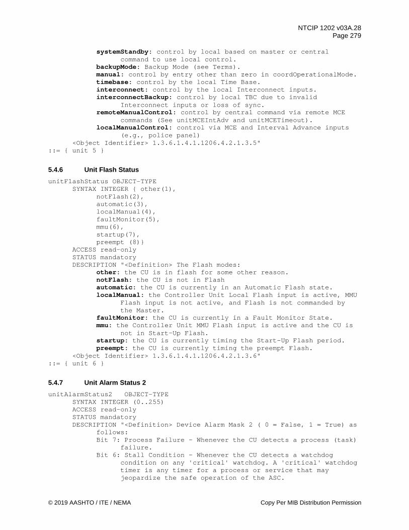
NTCIP 1202 v03A.28 Page 279
© 2019 AASHTO / ITE / NEMA Copy Per MIB Distribution Permission
systemStandby: control by local based on master or central command to use local control.
backupMode: Backup Mode (see Terms). manual: control by entry other than zero in coordOperationalMode. timebase: control by the local Time Base. interconnect: control by the local Interconnect inputs. interconnectBackup: control by local TBC due to invalid
Interconnect inputs or loss of sync. remoteManualControl: control by central command via remote MCE
commands (See unitMCEIntAdv and unitMCETimeout). localManualControl: control via MCE and Interval Advance inputs
(e.g., police panel) <Object Identifier> 1.3.6.1.4.1.1206.4.2.1.3.5"
::= { unit 5 }
5.4.6 Unit Flash Status unitFlashStatus OBJECT-TYPE
SYNTAX INTEGER { other(1), notFlash(2), automatic(3), localManual(4), faultMonitor(5), mmu(6), startup(7), preempt (8)}
ACCESS read-only STATUS mandatory DESCRIPTION "<Definition> The Flash modes:
other: the CU is in flash for some other reason. notFlash: the CU is not in Flash automatic: the CU is currently in an Automatic Flash state. localManual: the Controller Unit Local Flash input is active, MMU
Flash input is not active, and Flash is not commanded by the Master.
faultMonitor: the CU is currently in a Fault Monitor State. mmu: the Controller Unit MMU Flash input is active and the CU is
not in Start-Up Flash. startup: the CU is currently timing the Start-Up Flash period. preempt: the CU is currently timing the preempt Flash.
<Object Identifier> 1.3.6.1.4.1.1206.4.2.1.3.6" ::= { unit 6 }
5.4.7 Unit Alarm Status 2 unitAlarmStatus2 OBJECT-TYPE
SYNTAX INTEGER (0..255) ACCESS read-only STATUS mandatory DESCRIPTION "<Definition> Device Alarm Mask 2 ( 0 = False, 1 = True) as
follows: Bit 7: Process Failure - Whenever the CU detects a process (task)
failure. Bit 6: Stall Condition - Whenever the CU detects a watchdog
condition on any 'critical' watchdog. A 'critical' watchdog timer is any timer for a process or service that may jeopardize the safe operation of the ASC.
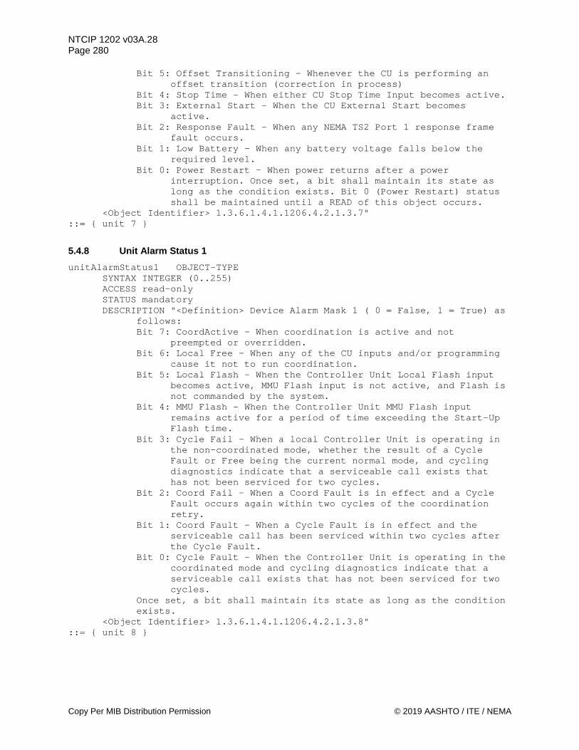
NTCIP 1202 v03A.28 Page 280
Copy Per MIB Distribution Permission © 2019 AASHTO / ITE / NEMA
Bit 5: Offset Transitioning - Whenever the CU is performing an offset transition (correction in process)
Bit 4: Stop Time - When either CU Stop Time Input becomes active. Bit 3: External Start - When the CU External Start becomes
active. Bit 2: Response Fault - When any NEMA TS2 Port 1 response frame
fault occurs. Bit 1: Low Battery - When any battery voltage falls below the
required level. Bit 0: Power Restart - When power returns after a power
interruption. Once set, a bit shall maintain its state as long as the condition exists. Bit 0 (Power Restart) status shall be maintained until a READ of this object occurs.
<Object Identifier> 1.3.6.1.4.1.1206.4.2.1.3.7" ::= { unit 7 }
5.4.8 Unit Alarm Status 1 unitAlarmStatus1 OBJECT-TYPE
SYNTAX INTEGER (0..255) ACCESS read-only STATUS mandatory DESCRIPTION "<Definition> Device Alarm Mask 1 ( 0 = False, 1 = True) as
follows: Bit 7: CoordActive - When coordination is active and not
preempted or overridden. Bit 6: Local Free - When any of the CU inputs and/or programming
cause it not to run coordination. Bit 5: Local Flash - When the Controller Unit Local Flash input
becomes active, MMU Flash input is not active, and Flash is not commanded by the system.
Bit 4: MMU Flash - When the Controller Unit MMU Flash input remains active for a period of time exceeding the Start-Up Flash time.
Bit 3: Cycle Fail - When a local Controller Unit is operating in the non-coordinated mode, whether the result of a Cycle Fault or Free being the current normal mode, and cycling diagnostics indicate that a serviceable call exists that has not been serviced for two cycles.
Bit 2: Coord Fail - When a Coord Fault is in effect and a Cycle Fault occurs again within two cycles of the coordination retry.
Bit 1: Coord Fault - When a Cycle Fault is in effect and the serviceable call has been serviced within two cycles after the Cycle Fault.
Bit 0: Cycle Fault - When the Controller Unit is operating in the coordinated mode and cycling diagnostics indicate that a serviceable call exists that has not been serviced for two cycles.
Once set, a bit shall maintain its state as long as the condition exists.
<Object Identifier> 1.3.6.1.4.1.1206.4.2.1.3.8" ::= { unit 8 }

NTCIP 1202 v03A.28 Page 281
© 2019 AASHTO / ITE / NEMA Copy Per MIB Distribution Permission
5.4.9 Short Alarm Status shortAlarmStatus OBJECT-TYPE
SYNTAX INTEGER (0..255) ACCESS read-only STATUS mandatory DESCRIPTION "<Definition> Short Alarm Mask ( 0 = False, 1 = True) as
follows: Bit 7: Critical Alarm - When the Stop Time input is active. Bit 6: Non-Critical Alarm - When an physical alarm input is
active. Bit 5: Detector Fault - When any detectorAlarm fault occurs. Bit 4: Coordination Alarm - When the CU is not running the called
pattern without offset correction within three cycles of the command. An offset correction requiring less than three cycles due to cycle overrun caused by servicing a pedestrian call shall not cause a Coordination Alarm.
Bit 3: Local Override - When any of the CU inputs and/or programming cause it not to run coordination.
Bit 2: Local Cycle Zero - When running coordinated and the Coord Cycle Status (coordCycleStatus) has passed through zero.
Bit 1: T&F Flash - When either the Local Flash or MMU Flash input becomes active.
Bit 0: Preempt - When any of the CU Preempt inputs become active. Once set, a bit shall maintain its state as long as the condition exists. Bit 2 (Local Cycle Zero) status shall be maintained until a READ of this object occurs.
<Object Identifier> 1.3.6.1.4.1.1206.4.2.1.3.9" ::= { unit 9 }
5.4.10 Unit Control unitControl OBJECT-TYPE
SYNTAX INTEGER (0..255) ACCESS read-write STATUS mandatory DESCRIPTION "<Definition> This object is used to allow a remote entity
to activate unit functions in the device ( 0 = False / Disabled, 1 = True / Enabled) as follows: Bit 7: Dimming Enable - when set to 1, causes channel dimming to
operate as configured. For dimming to occur, (this control OR a dimming input) AND a 'timebaseAscAuxillaryFunction' must be True. REFERENCE NEMA TS 2 Clause 3.9.2
Bit 6: Interconnect - when set to 1, shall cause the interconnect inputs to operate at a higher priority than the timebase control (TBC On Line). REFERENCE NEMA TS 2 Clause 3.6.2.3 and 3.8.3
Bit 5: Walk Rest Modifier - when set to 1, causes non-actuated phases to remain in the timed-out Walk state (rest in Walk) in the absence of a serviceable conflicting call. REFERENCE NEMA TS 2 Clause 3.5.5.5.13
Bit 4: Call to Non-Actuated 2 - when set to 1, causes any phase(s) appropriately programmed in the phaseOptions object to operate in the Non-Actuated Mode. REFERENCE NEMA TS 2 Clause 3.5.5.5.8
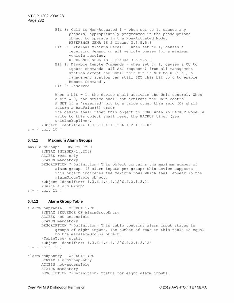
NTCIP 1202 v03A.28 Page 282
Copy Per MIB Distribution Permission © 2019 AASHTO / ITE / NEMA
Bit 3: Call to Non-Actuated 1 - when set to 1, causes any phase(s) appropriately programmed in the phaseOptions object to operate in the Non-Actuated Mode. REFERENCE NEMA TS 2 Clause 3.5.5.5.8
Bit 2: External Minimum Recall - when set to 1, causes a recurring demand on all vehicle phases for a minimum vehicle service. REFERENCE NEMA TS 2 Clause 3.5.5.5.9
Bit 1: Disable Remote Commands - when set to 1, causes a CU to ignore commands (all SET requests) from all management station except and until this bit is SET to 0 (i.e., a management station can still SET this bit to 0 to enable Remote Command).
Bit 0: Reserved When a bit = 1, the device shall activate the Unit control. When a bit = 0, the device shall not activate the Unit control. A SET of a 'reserved' bit to a value other than zero (0) shall return a badValue(3) error. The device shall reset this object to ZERO when in BACKUP Mode. A write to this object shall reset the BACKUP timer (see unitBackupTime).
<Object Identifier> 1.3.6.1.4.1.1206.4.2.1.3.10" ::= { unit 10 }
5.4.11 Maximum Alarm Groups maxAlarmGroups OBJECT-TYPE
SYNTAX INTEGER(1..255) ACCESS read-only STATUS mandatory DESCRIPTION "<Definition> This object contains the maximum number of
alarm groups (8 alarm inputs per group) this device supports. This object indicates the maximum rows which shall appear in the alarmGroupTable object.
<Object Identifier> 1.3.6.1.4.1.1206.4.2.1.3.11 <Unit> alarm Group"
::= { unit 11 }
5.4.12 Alarm Group Table alarmGroupTable OBJECT-TYPE
SYNTAX SEQUENCE OF AlarmGroupEntry ACCESS not-accessible STATUS mandatory DESCRIPTION "<Definition> This table contains alarm input status in
groups of eight inputs. The number of rows in this table is equal to the maxAlarmGroups object.
<TableType> static <Object Identifier> 1.3.6.1.4.1.1206.4.2.1.3.12"
::= { unit 12 } alarmGroupEntry OBJECT-TYPE
SYNTAX AlarmGroupEntry ACCESS not-accessible STATUS mandatory DESCRIPTION "<Definition> Status for eight alarm inputs.

NTCIP 1202 v03A.28 Page 283
© 2019 AASHTO / ITE / NEMA Copy Per MIB Distribution Permission
<Object Identifier> 1.3.6.1.4.1.1206.4.2.1.3.12.1" INDEX { alarmGroupNumber }
::= { alarmGroupTable 1 } AlarmGroupEntry::= SEQUENCE {
alarmGroupNumber INTEGER, alarmGroupState INTEGER}
5.4.12.1 Alarm Group Number alarmGroupNumber OBJECT-TYPE
SYNTAX INTEGER (1..255) ACCESS read-only STATUS mandatory DESCRIPTION "<Definition> The alarm group number for objects in this
row. This value shall not exceed the maxAlarmGroups object value. <Object Identifier> 1.3.6.1.4.1.1206.4.2.1.3.12.1.1 <Unit> group"
::= { alarmGroupEntry 1 }
5.4.12.2 Alarm Group State alarmGroupState OBJECT-TYPE
SYNTAX INTEGER (0..255) ACCESS read-only STATUS mandatory DESCRIPTION "<Definition> Alarm input state bit field. When a bit = 1,
the associated physical alarm input is active. When a bit = 0, the associated alarm input is NOT active. Bit 7: Alarm Input # = ( alarmGroupNumber * 8) Bit 6: Alarm Input # = ( alarmGroupNumber * 8) -1 Bit 5: Alarm Input # = ( alarmGroupNumber * 8) -2 Bit 4: Alarm Input # = ( alarmGroupNumber * 8) -3 Bit 3: Alarm Input # = ( alarmGroupNumber * 8) -4 Bit 2: Alarm Input # = ( alarmGroupNumber * 8) -5 Bit 1: Alarm Input # = ( alarmGroupNumber * 8) -6 Bit 0: Alarm Input # = ( alarmGroupNumber * 8) -7
<Object Identifier> 1.3.6.1.4.1.1206.4.2.1.3.12.1.2" ::= {alarmGroupEntry 2 }
5.4.13 Maximum Special Function Outputs maxSpecialFunctionOutputs OBJECT-TYPE
SYNTAX INTEGER (1..255) ACCESS read-only STATUS mandatory DESCRIPTION "<Definition> The Maximum Number of Special Functions this
Actuated Controller Unit supports. <Object Identifier> 1.3.6.1.4.1.1206.4.2.1.3.13 <Unit> output"
::= { unit 13 }
5.4.14 Special Function Output Table specialFunctionOutputTable OBJECT-TYPE
SYNTAX SEQUENCE OF SpecialFunctionOutputEntry

NTCIP 1202 v03A.28 Page 284
Copy Per MIB Distribution Permission © 2019 AASHTO / ITE / NEMA
ACCESS not-accessible STATUS mandatory DESCRIPTION "<Definition> A table containing Actuated Controller Unit
special function output objects. The number of rows in this table is equal to the maxSpecialFunctionOutputs object.
<TableType> static <Object Identifier> 1.3.6.1.4.1.1206.4.2.1.3.14"
::= { unit 14 } specialFunctionOutputEntry OBJECT-TYPE
SYNTAX SpecialFunctionOutputEntry ACCESS not-accessible STATUS mandatory DESCRIPTION "<Definition> Control for Actuated Controller Unit system
special functions. <Object Identifier> 1.3.6.1.4.1.1206.4.2.1.3.14.1" INDEX { specialFunctionOutputNumber }
::= { specialFunctionOutputTable 1 } SpecialFunctionOutputEntry ::= SEQUENCE {
specialFunctionOutputNumber INTEGER, specialFunctionOutputState INTEGER, -- deprecated specialFunctionOutputControl INTEGER, specialFunctionOutputStatus INTEGER }
5.4.14.1 Special Function Output Number specialFunctionOutputNumber OBJECT-TYPE
SYNTAX INTEGER (1..255) ACCESS read-only STATUS mandatory DESCRIPTION "<Definition> The special function output number associated
with object in this row. This value shall not exceed the maxSpecialFunctionOutputs object value.
<Object Identifier> 1.3.6.1.4.1.1206.4.2.1.3.14.1.1 <Unit> output"
::= { specialFunctionOutputEntry 1 }
5.4.14.2 Special Function Output State specialFunctionOutputState OBJECT-TYPE
SYNTAX INTEGER (0..1) ACCESS read-write STATUS deprecated DESCRIPTION "<Definition> The special function output (logical or
physical) on the device may be controlled by this object. When this object is non-zero then the associated special function output signal shall be ON. When this object is zero then the associated special function output signal shall be OFF A read of this object shall reflect the current state of the special function output.
<Object Identifier> 1.3.6.1.4.1.1206.4.2.1.3.14.1.2" ::= { specialFunctionOutputEntry 2 }
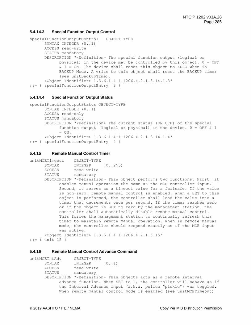
NTCIP 1202 v03A.28 Page 285
© 2019 AASHTO / ITE / NEMA Copy Per MIB Distribution Permission
5.4.14.3 Special Function Output Control specialFunctionOutputControl OBJECT-TYPE
SYNTAX INTEGER (0..1) ACCESS read-write STATUS mandatory DESCRIPTION "<Definition> The special function output (logical or
physical) in the device may be controlled by this object. 0 = OFF & 1 = ON. The device shall reset this object to ZERO when in BACKUP Mode. A write to this object shall reset the BACKUP timer (see unitBackupTime).
<Object Identifier> 1.3.6.1.4.1.1206.4.2.1.3.14.1.3" ::= { specialFunctionOutputEntry 3 }
5.4.14.4 Special Function Output Status specialFunctionOutputStatus OBJECT-TYPE
SYNTAX INTEGER (0..1) ACCESS read-only STATUS mandatory DESCRIPTION "<Definition> The current status (ON-OFF) of the special
function output (logical or physical) in the device. 0 = OFF & 1 = ON.
<Object Identifier> 1.3.6.1.4.1.1206.4.2.1.3.14.1.4" ::= { specialFunctionOutputEntry 4 }
5.4.15 Remote Manual Control Timer unitMCETimeout OBJECT-TYPE
SYNTAX INTEGER (0..255) ACCESS read-write STATUS mandatory DESCRIPTION "<Definition> This object performs two functions. First, it
enables manual operation the same as the MCE controller input. Second, it serves as a timeout value for a failsafe. If the value is non-zero, remote manual control is enabled. When a SET to this object is performed, the controller shall load the value into a timer that decrements once per second. If the timer reaches zero or if the object is SET to zero by the management station, the controller shall automatically disable remote manual control. This forces the management station to continually refresh this timer to maintain remote manual operation. When in remote manual mode, the controller should respond exactly as if the MCE input was active.
<Object Identifier> 1.3.6.1.4.1.1206.4.2.1.3.15" ::= { unit 15 }
5.4.16 Remote Manual Control Advance Command unitMCEIntAdv OBJECT-TYPE
SYNTAX INTEGER (0..1) ACCESS read-write STATUS mandatory DESCRIPTION "<Definition> This objects acts as a remote interval
advance function. When SET to 1, the controller will behave as if the Interval Advance input (a.k.a. police “pickle”) was toggled. When remote manual control mode is enabled (see unitMCETimeout)
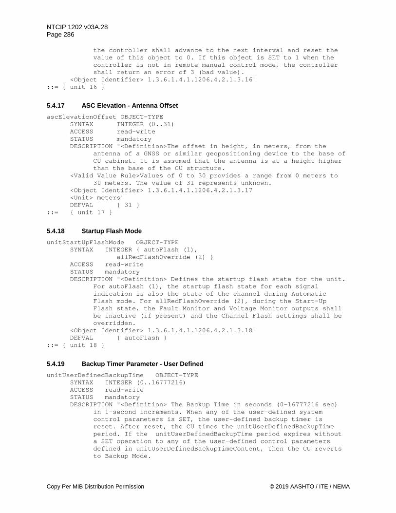
NTCIP 1202 v03A.28 Page 286
Copy Per MIB Distribution Permission © 2019 AASHTO / ITE / NEMA
the controller shall advance to the next interval and reset the value of this object to 0. If this object is SET to 1 when the controller is not in remote manual control mode, the controller shall return an error of 3 (bad value).
<Object Identifier> 1.3.6.1.4.1.1206.4.2.1.3.16" ::= { unit 16 }
5.4.17 ASC Elevation - Antenna Offset ascElevationOffset OBJECT-TYPE
SYNTAX INTEGER (0..31) ACCESS read-write STATUS mandatory DESCRIPTION "<Definition>The offset in height, in meters, from the
antenna of a GNSS or similar geopositioning device to the base of CU cabinet. It is assumed that the antenna is at a height higher than the base of the CU structure.
<Valid Value Rule>Values of 0 to 30 provides a range from 0 meters to 30 meters. The value of 31 represents unknown.
<Object Identifier> 1.3.6.1.4.1.1206.4.2.1.3.17 <Unit> meters" DEFVAL { 31 }
::= { unit 17 }
5.4.18 Startup Flash Mode unitStartUpFlashMode OBJECT-TYPE
SYNTAX INTEGER { autoFlash (1), allRedFlashOverride (2) }
ACCESS read-write STATUS mandatory DESCRIPTION "<Definition> Defines the startup flash state for the unit.
For autoFlash (1), the startup flash state for each signal indication is also the state of the channel during Automatic Flash mode. For allRedFlashOverride (2), during the Start-Up Flash state, the Fault Monitor and Voltage Monitor outputs shall be inactive (if present) and the Channel Flash settings shall be overridden.
<Object Identifier> 1.3.6.1.4.1.1206.4.2.1.3.18" DEFVAL { autoFlash }
::= { unit 18 }
5.4.19 Backup Timer Parameter - User Defined unitUserDefinedBackupTime OBJECT-TYPE
SYNTAX INTEGER (0..16777216) ACCESS read-write STATUS mandatory DESCRIPTION "<Definition> The Backup Time in seconds (0-16777216 sec)
in 1-second increments. When any of the user-defined system control parameters is SET, the user-defined backup timer is reset. After reset, the CU times the unitUserDefinedBackupTime period. If the unitUserDefinedBackupTime period expires without a SET operation to any of the user-defined control parameters defined in unitUserDefinedBackupTimeContent, then the CU reverts to Backup Mode.

NTCIP 1202 v03A.28 Page 287
© 2019 AASHTO / ITE / NEMA Copy Per MIB Distribution Permission
A value of zero (0) for this object shall disable this feature. If the value of this object is non-zero, then all functionality related to unitBackupTime is diabled.
<Object Identifier> 1.3.6.1.4.1.1206.4.2.1.3.19 <Unit> second" DEFVAL {300}
::= { unit 19 }
5.4.20 Maximum Number of User Definable OIDs for Backup Timer maxUserDefinedBackupTimeContent OBJECT-TYPE
SYNTAX INTEGER (2..255) ACCESS read-only STATUS mandatory DESCRIPTION "<Definition> The Maximum Number of user content backup
time contents this controller supports. This object indicates the maximum rows which shall appear in the unitUserDefinedBackupTimeContentTable object.
<Object Identifier> 1.3.6.1.4.1.1206.4.2.1.3.20 <Unit> phase"
::= { unit 20 }
5.4.21 Backup Time - User Defined Functions Table unitUserDefinedBackupTimeContentTable OBJECT-TYPE
SYNTAX SEQUENCE OF UnitUserDefinedBackupTimeContentEntry ACCESS not-accessible STATUS mandatory DESCRIPTION "<Definition> A table containing the parameters of the user
defined parameters for the backup timer. <TableType> static <Object Identifier> 1.3.6.1.4.1.1206.4.2.1.3.21"
::= { unit 21 } unitUserDefinedBackupTimeContentEntry OBJECT-TYPE
SYNTAX UnitUserDefinedBackupTimeContentEntry ACCESS not-accessible STATUS mandatory DESCRIPTION "<Definition> Parameters for a user-defined backup timer. <Object Identifier> 1.3.6.1.4.1.1206.4.2.1.3.21.1" INDEX { unitUserDefinedBackupTimeContentNumber }
::= { unitUserDefinedBackupTimeContentTable 1 } UnitUserDefinedBackupTimeContentEntry ::= SEQUENCE {
unitUserDefinedBackupTimeContentNumber INTEGER, unitUserDefinedBackupTimeContentOID OBJECT IDENTIFIER, unitUserDefinedBackupTimeContentDescription OCTET STRING }
5.4.21.1 Backup Time - User Defined Number unitUserDefinedBackupTimeContentNumber OBJECT-TYPE
SYNTAX INTEGER (1..65535) ACCESS read-only STATUS mandatory

NTCIP 1202 v03A.28 Page 288
Copy Per MIB Distribution Permission © 2019 AASHTO / ITE / NEMA
DESCRIPTION "<Definition> A userDefinedBackupTimeContent number for objects in this row. The value shall not exceed maxUserDefinedBackupTimeContents object value.
<Object Identifier> 1.3.6.1.4.1.1206.4.2.1.3.21.1.1 <Unit> number"
::= { unitUserDefinedBackupTimeContentEntry 1 }
5.4.21.2 Backup Time - User Defined OID unitUserDefinedBackupTimeContentOID OBJECT-TYPE
SYNTAX OBJECT IDENTIFIER ACCESS read-write STATUS mandatory DESCRIPTION "<Definition> This object contains a reference to the
function, which, if any SET operation is performed on it, leads to a reset of the timer associated with the unitUserDefinedbackupTime object. This object shall reference the function by its associated identifier including its instance (i.e., the full OID of the scalar or columnar object).
<Object Identifier> 1.3.6.1.4.1.1206.4.2.1.3.21.1.2" DEFVAL { null }
::= { unitUserDefinedBackupTimeContentEntry 2 }
5.4.21.3 Backup Time - User Defined Content Description unitUserDefinedBackupTimeContentDescription OBJECT-TYPE
SYNTAX OCTET STRING ACCESS read-write STATUS mandatory DESCRIPTION "<Definition> Contains a text description of the referenced
function that, if performing a SET command against its corresponding object, will reset the timer associated with the unitUserDefinedBackupTime object.
<Object Identifier> 1.3.6.1.4.1.1206.4.2.1.3.21.1.3" DEFVAL { "" }
::= { unitUserDefinedBackupTimeContentEntry 3 }
5.4.22 ASC Clock ascClock OBJECT IDENTIFIER ::= { unit 22 } -- This note contains the objects necessary to support time sources.
5.4.22.1 Maximum Number of Time Sources maxTimeSources OBJECT-TYPE
SYNTAX INTEGER (1..255) ACCESS read-only STATUS mandatory DESCRIPTION "<Definition> The maximum number of time sources that this
Controller Unit supports. This object indicates the maximum rows which shall appear in the unitTimeTable object.
<Object Identifier> 1.3.6.1.4.1.1206.4.2.1.3.22.1 <Unit> timeSource"
::= { ascClock 1 }

NTCIP 1202 v03A.28 Page 289
© 2019 AASHTO / ITE / NEMA Copy Per MIB Distribution Permission
5.4.22.2 Unit Time Source Table unitTimeTable OBJECT-TYPE
SYNTAX SEQUENCE OF UnitTimeEntry ACCESS not-accessible STATUS mandatory DESCRIPTION "<Definition> A table containing Controller Unit time
sources. The number of rows in this table is equal to the maxTimeSources object.
<TableType> static <Object Identifier> 1.3.6.1.4.1.1206.4.2.1.3.22.2"
::= { ascClock 2 } unitTimeEntry OBJECT-TYPE
SYNTAX UnitTimeEntry ACCESS not-accessible STATUS mandatory DESCRIPTION "<Definition> Parameters for a specific Controller Unit
time source. <Object Identifier> 1.3.6.1.4.1.1206.4.2.1.3.22.2.1" INDEX { unitTimeIndex }
::= { unitTimeTable 1 } UnitTimeEntry ::= SEQUENCE { unitTimeIndex INTEGER, unitTimeSourceAvailable INTEGER }
5.4.22.2.1 Unit Time Source Index unitTimeIndex OBJECT-TYPE
SYNTAX INTEGER (1..255) ACCESS read-only STATUS mandatory DESCRIPTION "<Definition> The index number for objects in this row. The
value shall not exceed the maxTimeSources object value. <Object Identifier> 1.3.6.1.4.1.1206.4.2.1.3.22.2.1.1 <Unit> timeSource"
::= { unitTimeEntry 1 }
5.4.22.2.2 Unit Time Source unitTimeSourceAvailable OBJECT-TYPE
SYNTAX INTEGER { other (1), lineSync (2),
rtcSqwr (3), crystal (4), gnss (5),
ntp (6) } ACCESS read-only STATUS mandatory DESCRIPTION "<Definition> An enumerated value representing the
available sources for adjusting the clock. This object sets up the clock sources available for use by the CU. other: the source of the unit time is not defined by this
standard.
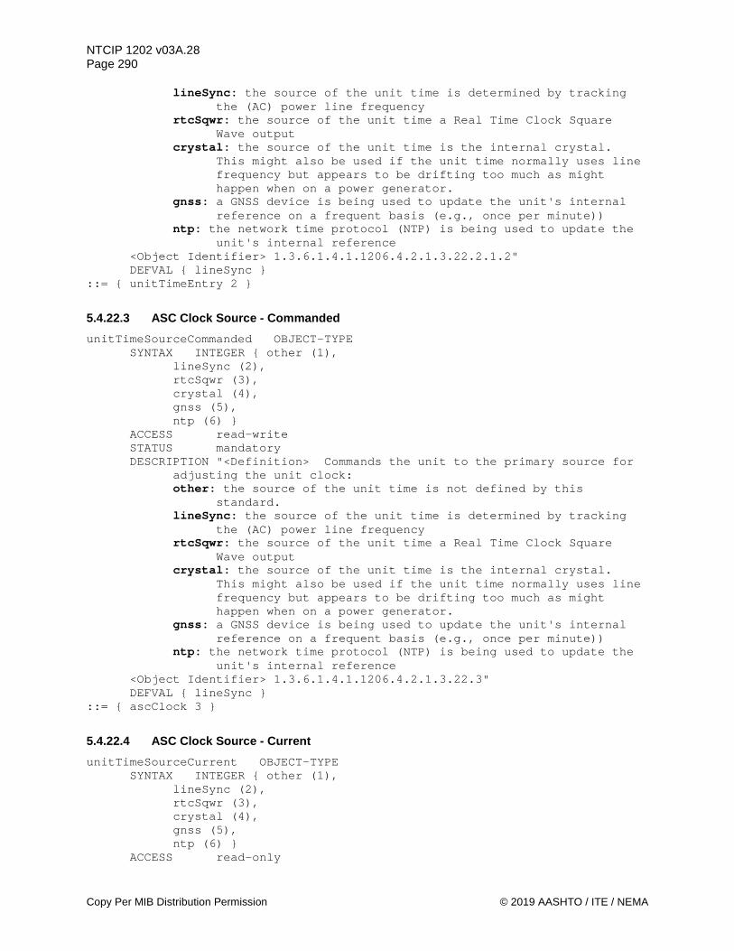
NTCIP 1202 v03A.28 Page 290
Copy Per MIB Distribution Permission © 2019 AASHTO / ITE / NEMA
lineSync: the source of the unit time is determined by tracking the (AC) power line frequency
rtcSqwr: the source of the unit time a Real Time Clock Square Wave output
crystal: the source of the unit time is the internal crystal. This might also be used if the unit time normally uses line frequency but appears to be drifting too much as might happen when on a power generator.
gnss: a GNSS device is being used to update the unit's internal reference on a frequent basis (e.g., once per minute))
ntp: the network time protocol (NTP) is being used to update the unit's internal reference
<Object Identifier> 1.3.6.1.4.1.1206.4.2.1.3.22.2.1.2" DEFVAL { lineSync }
::= { unitTimeEntry 2 }
5.4.22.3 ASC Clock Source - Commanded unitTimeSourceCommanded OBJECT-TYPE
SYNTAX INTEGER { other (1), lineSync (2),
rtcSqwr (3), crystal (4), gnss (5),
ntp (6) } ACCESS read-write STATUS mandatory DESCRIPTION "<Definition> Commands the unit to the primary source for
adjusting the unit clock: other: the source of the unit time is not defined by this
standard. lineSync: the source of the unit time is determined by tracking
the (AC) power line frequency rtcSqwr: the source of the unit time a Real Time Clock Square
Wave output crystal: the source of the unit time is the internal crystal.
This might also be used if the unit time normally uses line frequency but appears to be drifting too much as might happen when on a power generator.
gnss: a GNSS device is being used to update the unit's internal reference on a frequent basis (e.g., once per minute))
ntp: the network time protocol (NTP) is being used to update the unit's internal reference
<Object Identifier> 1.3.6.1.4.1.1206.4.2.1.3.22.3" DEFVAL { lineSync }
::= { ascClock 3 }
5.4.22.4 ASC Clock Source - Current unitTimeSourceCurrent OBJECT-TYPE
SYNTAX INTEGER { other (1), lineSync (2),
rtcSqwr (3), crystal (4), gnss (5),
ntp (6) } ACCESS read-only

NTCIP 1202 v03A.28 Page 291
© 2019 AASHTO / ITE / NEMA Copy Per MIB Distribution Permission
STATUS mandatory DESCRIPTION "<Definition> An enumerated value representing the current
source for adjusting the unit clock as follows: other: the source of the unit time is not defined by this
standard. lineSync: the source of the unit time is determined by tracking
the (AC) power line frequency rtcSqwr: the source of the unit time is a Real Time Clock Square
Wave output crystal: the source of the unit time is the internal crystal.
This might also be used if the unit time normally uses line frequency but appears to be drifting too much as might happen when on a power generator.
gnss: a GNSS device is being used to update the unit's internal reference on a frequent basis (e.g., once per minute))
ntp: the network time protocol (NTP) is being used to update the unit's internal reference
<Object Identifier> 1.3.6.1.4.1.1206.4.2.1.3.22.4" DEFVAL { lineSync }
::= { ascClock 4 }
5.4.22.5 Unit Time Source Status unitTimeSourceStatus OBJECT-TYPE
SYNTAX INTEGER { notActive (1), active (2),
dataError (3), dataTimeOutError (4), pendingUpdate (5),
nonSequential (6) } ACCESS read-only STATUS mandatory DESCRIPTION "<Definition> An enumerated value representing the status
of the current unit clock source (unitTimeSourceCurrent). notActive: The unit is not monitoring this clock source, or
updates are not available. active: The unit is receiving valid updates and is updating the
controller time without errors. dataError: A data error, such as a crc mismatch, was detected. dataTimeoutError: No data has been received from the
unitTimeSourceCurrent within a reasonable amount of time. This timeout will be preset by the driver for this time source as it depends on the specific implementation.
pendingUpdate: The unit is pending an update from the unitTimeSourceCurrent, such as when the controller is in the startup period and is waiting for the external device to sync to its reference and send the time to the unit.
nonSequential: A non-sequential clock change occurrence. Note this value should be cleared upon reading it (i.e., a GET on this object) or 10 seconds after its occurrence, whichever comes first.
<Object Identifier> 1.3.6.1.4.1.1206.4.2.1.3.22.5" ::= { ascClock 5 }
5.4.22.6 ASC Clock Non-Sequential Time Source unitTimeNonSequentialSource OBJECT-TYPE

NTCIP 1202 v03A.28 Page 292
Copy Per MIB Distribution Permission © 2019 AASHTO / ITE / NEMA
SYNTAX INTEGER { unknown (1), dstChange (2), managementStation (3), localUser (4), timeSourceChange (5), timeSourceDiscontinuity (6) }
ACCESS read-only STATUS mandatory DESCRIPTION "<Definition> An enumerated value that indicates the source
of a non-sequential change to the ASC clock time. A non-sequential change occurs anytime the clock changes by more than 1 increment (whether in seconds or milliseconds). unknown: the source of the non-sequential change to the unit time
is unknown or cannot be determined. dstChange: the source of the non-sequential change to the unit
time is a change in daytime savings time. managementStation: the source of the non-sequential change to the
unit time is a command from a management station. localUser: the source of the non-sequential change to the unit
time is a command from a user or device at the controller unit.
timeSourceChange: A change in the time source (e.g., external1) timeSourceDiscontinuity: A change as determined by an external
time source (e.g., GNSS). The value is latched until another non-sequential change to the
ASC clock time or until the ASC is powered off. If a non-sequential change occurs or globalTime is SET, then the
event should be logged. This object is used with the unitTimeNonSequentialChange and the unitTimeNonSequentialDelta objects.
<Object Identifier> 1.3.6.1.4.1.1206.4.2.1.3.22.6" DEFVAL { unknown }
::= { ascClock 6 }
5.4.22.7 ASC Clock Non-Sequential Time Change unitTimeNonSequentialChange OBJECT-TYPE
SYNTAX Counter ACCESS read-only STATUS mandatory DESCRIPTION "<Definition> The 'new' globalTime after a non-sequential
change to the ASC clock time. A non-sequential change occurs anytime the clock changes by more than 1 increment (whether in seconds or milliseconds). The value of this object is number of seconds since the epoch of 00:00:00 (midnight) January 1, 1970 UTC (a.k.a. Zulu or GMT).
<Object Identifier> 1.3.6.1.4.1.1206.4.2.1.3.22.7 <Unit> second" DEFVAL { 0 }
::= { ascClock 7 }
5.4.22.8 ASC Clock Non-Sequential Time Difference unitTimeNonSequentialDelta OBJECT-TYPE
SYNTAX OCTET STRING (SIZE(0 | 5)) ACCESS read-only STATUS mandatory
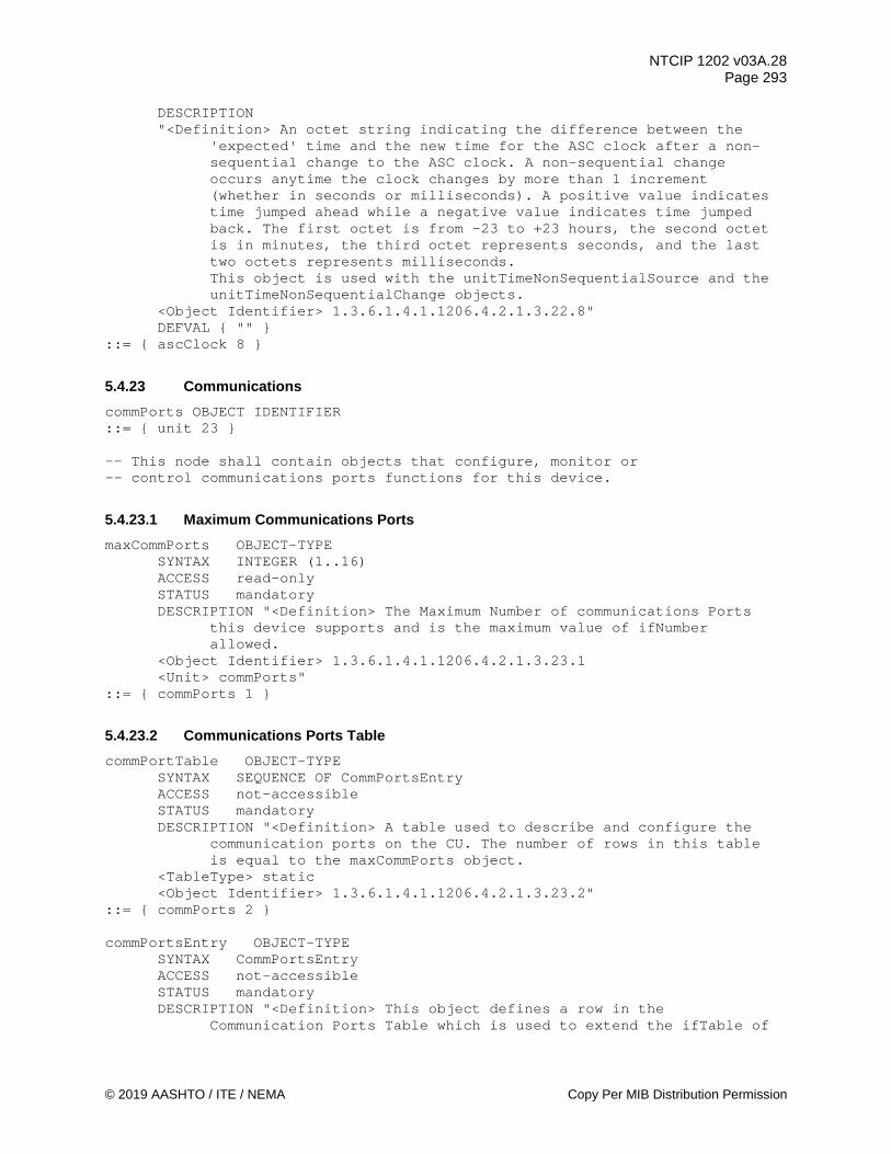
NTCIP 1202 v03A.28 Page 293
© 2019 AASHTO / ITE / NEMA Copy Per MIB Distribution Permission
DESCRIPTION "<Definition> An octet string indicating the difference between the
'expected' time and the new time for the ASC clock after a non-sequential change to the ASC clock. A non-sequential change occurs anytime the clock changes by more than 1 increment (whether in seconds or milliseconds). A positive value indicates time jumped ahead while a negative value indicates time jumped back. The first octet is from -23 to +23 hours, the second octet is in minutes, the third octet represents seconds, and the last two octets represents milliseconds. This object is used with the unitTimeNonSequentialSource and the unitTimeNonSequentialChange objects.
<Object Identifier> 1.3.6.1.4.1.1206.4.2.1.3.22.8" DEFVAL { "" }
::= { ascClock 8 }
5.4.23 Communications commPorts OBJECT IDENTIFIER ::= { unit 23 } -- This node shall contain objects that configure, monitor or -- control communications ports functions for this device.
5.4.23.1 Maximum Communications Ports maxCommPorts OBJECT-TYPE
SYNTAX INTEGER (1..16) ACCESS read-only STATUS mandatory DESCRIPTION "<Definition> The Maximum Number of communications Ports
this device supports and is the maximum value of ifNumber allowed.
<Object Identifier> 1.3.6.1.4.1.1206.4.2.1.3.23.1 <Unit> commPorts"
::= { commPorts 1 }
5.4.23.2 Communications Ports Table commPortTable OBJECT-TYPE
SYNTAX SEQUENCE OF CommPortsEntry ACCESS not-accessible STATUS mandatory DESCRIPTION "<Definition> A table used to describe and configure the
communication ports on the CU. The number of rows in this table is equal to the maxCommPorts object.
<TableType> static <Object Identifier> 1.3.6.1.4.1.1206.4.2.1.3.23.2"
::= { commPorts 2 } commPortsEntry OBJECT-TYPE
SYNTAX CommPortsEntry ACCESS not-accessible STATUS mandatory DESCRIPTION "<Definition> This object defines a row in the
Communication Ports Table which is used to extend the ifTable of

NTCIP 1202 v03A.28 Page 294
Copy Per MIB Distribution Permission © 2019 AASHTO / ITE / NEMA
RFC 1213. It uses ifIndex from RFC 1213 as the index, so all communications ports in the controller has to be included in the ifTable including async RS232 ports which are also in the rs232PortTable.
<Object Identifier> 1.3.6.1.4.1.1206.4.2.1.3.23.2.1" INDEX { ifIndex }
::= { commPortTable 1 } CommPortsEntry ::= SEQUENCE {
commPortType INTEGER, commPortTypeIndex INTEGER, commPortEnable INTEGER, commPortProtocolsSupported INTEGER, commPortProtocol INTEGER, commPortDiagnostics INTEGER }
5.4.23.2.1 Communications Port Type commPortType OBJECT-TYPE
SYNTAX INTEGER { other (1), ethernet (2), rs232like (3) }
ACCESS read-only STATUS mandatory DESCRIPTION "<Definition> This object identifies the port type.
Although RFC 1213 contains ifType, this object provides the user/device further guidance to additional objects that define the port and its configuration. The valid port types are defined as follows: other: the port type is not defined by this standard. Ethernet: the port type is Ethernet based (i.e. IP) and configured per NTCIP 2104 and 2202 rs232like: the port type is rs-232-like (per RFC 1317) and may be either an asynchronous or synchronous serial. Port configuration is contained in RFC 1317 rs232PortTable
<Object Identifier> 1.3.6.1.4.1.1206.4.2.1.3.23.2.1.1" ::= { commPortsEntry 1 }
5.4.23.2.2 Communications Port Type Number Parameter commPortTypeIndex OBJECT-TYPE
SYNTAX INTEGER ACCESS read-write STATUS mandatory DESCRIPTION "<Definition> This object contains the value to be used as
the index into the appropriate communication port configuration table. If commPortType = rs232like, then this value is used for RFC 1317 rs232PortIndex into the rs232PortTable. If commPortType is ethernet then this object is redundant and should have the same value as ifIndex.
<Object Identifier> 1.3.6.1.4.1.1206.4.2.1.3.23.2.1.2" ::= { commPortsEntry 2 }
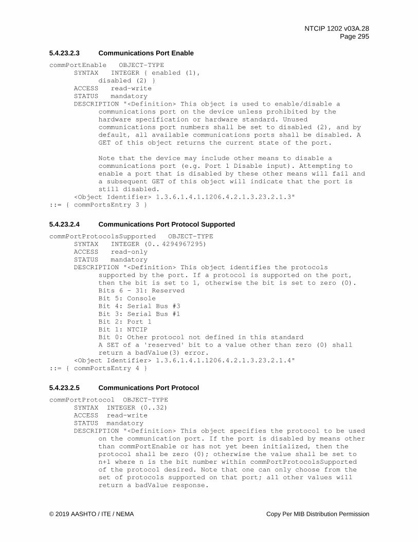
NTCIP 1202 v03A.28 Page 295
© 2019 AASHTO / ITE / NEMA Copy Per MIB Distribution Permission
5.4.23.2.3 Communications Port Enable commPortEnable OBJECT-TYPE
SYNTAX INTEGER { enabled (1), disabled (2) }
ACCESS read-write STATUS mandatory DESCRIPTION "<Definition> This object is used to enable/disable a
communications port on the device unless prohibited by the hardware specification or hardware standard. Unused communications port numbers shall be set to disabled (2), and by default, all available communications ports shall be disabled. A GET of this object returns the current state of the port.
Note that the device may include other means to disable a communications port (e.g. Port 1 Disable input). Attempting to enable a port that is disabled by these other means will fail and a subsequent GET of this object will indicate that the port is still disabled.
<Object Identifier> 1.3.6.1.4.1.1206.4.2.1.3.23.2.1.3" ::= { commPortsEntry 3 }
5.4.23.2.4 Communications Port Protocol Supported commPortProtocolsSupported OBJECT-TYPE
SYNTAX INTEGER (0.. 4294967295) ACCESS read-only STATUS mandatory DESCRIPTION "<Definition> This object identifies the protocols
supported by the port. If a protocol is supported on the port, then the bit is set to 1, otherwise the bit is set to zero (0).
Bits 6 - 31: Reserved Bit 5: Console Bit 4: Serial Bus #3 Bit 3: Serial Bus #1 Bit 2: Port 1 Bit 1: NTCIP Bit 0: Other protocol not defined in this standard
A SET of a 'reserved' bit to a value other than zero (0) shall return a badValue(3) error.
<Object Identifier> 1.3.6.1.4.1.1206.4.2.1.3.23.2.1.4" ::= { commPortsEntry 4 }
5.4.23.2.5 Communications Port Protocol commPortProtocol OBJECT-TYPE
SYNTAX INTEGER (0..32) ACCESS read-write STATUS mandatory DESCRIPTION "<Definition> This object specifies the protocol to be used
on the communication port. If the port is disabled by means other than commPortEnable or has not yet been initialized, then the protocol shall be zero (0); otherwise the value shall be set to n+1 where n is the bit number within commPortProtocolsSupported of the protocol desired. Note that one can only choose from the set of protocols supported on that port; all other values will return a badValue response.
NTCIP 1202 v03A.28 Page 296
Copy Per MIB Distribution Permission © 2019 AASHTO / ITE / NEMA
<Object Identifier> 1.3.6.1.4.1.1206.4.2.1.3.23.2.1.5" ::= { commPortsEntry 5 }
5.4.23.2.6 Communications Port Diagnostics commPortDiagnostics OBJECT-TYPE
SYNTAX INTEGER { normal (1), loopback (2), echomode (3) }
ACCESS read-write STATUS mandatory DESCRIPTION "<Definition> This object specifies the port diagnostic
commands for a communication port. It works in conjunction with ifOperStatus and ifAdminStatus from RFC 1213. Setting this object to loopback or echomode will result in ifAdminStatus being set to 'testing' and if successful the device will update ifOperStatus to testing. When ifAdminStatus is set to either 'up' or 'down', if successful the device will update ifOperStatus accordingly and set this object to 'normal'. One cannot directly set this object to 'normal'.
Note that a user can enable/disable each communications port on the device unless prohibited by the PRL or hardware standard/specification. Unused communications port numbers shall be set to disabled ('down'), and by default, all available communications ports shall be enabled. Note that the device may include other means to disable a communications port (e.g. Port 1 Disable input). Attempting to enable a port that is disabled by these other means will fail and a subsequent GET of this object will indicate that the port is still disabled.
<Object Identifier> 1.3.6.1.4.1.1206.4.2.1.3.23.2.1.6" ::= { commPortsEntry 6 }
5.4.23.3 Maximum Ethernet Ports maxEthernetPorts OBJECT-TYPE
SYNTAX INTEGER (1..255) ACCESS read-only STATUS mandatory DESCRIPTION "<Definition> The Maximum Number of Ethernet
communications ports this device supports. This object indicates the maximum rows which shall appear in the ethernetConfigTable object.
<Object Identifier> 1.3.6.1.4.1.1206.4.2.1.3.23.3 <Unit> ethernetPorts"
::= { commPorts 3 }
5.4.23.4 Ethernet Port Configuration Table ethernetConfigTable OBJECT-TYPE
SYNTAX SEQUENCE OF EthernetConfigEntry ACCESS not-accessible STATUS mandatory

NTCIP 1202 v03A.28 Page 297
© 2019 AASHTO / ITE / NEMA Copy Per MIB Distribution Permission
DESCRIPTION "<Definition> This table extends configurations for the Ethernet ports on the device by providing objects that extend standard configuration tables such as those contained in RFC 1213.
The number of rows in this table is equal to the maxEthernetPorts object. This table only contains rows for communication ports with commPortType = ethernet (2).
Note that the Ethernet port’s MAC address can be found via the ifPhysAddress object in the ifTable at the same value of ifIndex.
<TableType> static <Object Identifier> 1.3.6.1.4.1.1206.4.2.1.3.23.4"
::= { commPorts 4 } ethernetConfigEntry OBJECT-TYPE
SYNTAX EthernetConfigEntry ACCESS not-accessible STATUS mandatory DESCRIPTION "<Definition> This object defines a row in the Ethernet
Port Configuration Table. <Object Identifier> 1.3.6.1.4.1.1206.4.2.1.3.23.4.1" INDEX { ifIndex }
::= { ethernetConfigTable 1 } EthernetConfigEntry ::= SEQUENCE {
ecfgIpAddr IpAddress, ecfgNetMask IpAddress, ecfgGateway IpAddress, ecfgDNS IpAddress, ecfgMode INTEGER, ecfgLogicalName OCTET STRING, ecfgStaticIpAddr IpAddress, ecfgStaticNetMask IpAddress, ecfgStaticGateway IpAddress, ecfgStaticDNS IpAddress }
5.4.23.4.1 IP Address Parameter ecfgIpAddr OBJECT-TYPE
SYNTAX IpAddress ACCESS read-only STATUS mandatory DESCRIPTION "<Definition> This object contains the IP address of this
logical Ethernet Port. <Object Identifier> 1.3.6.1.4.1.1206.4.2.1.3.23.4.1.1"
::= { ethernetConfigEntry 1 }
5.4.23.4.2 Net Mask Parameter ecfgNetMask OBJECT-TYPE
SYNTAX IpAddress ACCESS read-only STATUS mandatory DESCRIPTION "<Definition> This object contains the network mask for
this Ethernet Port. <Object Identifier> 1.3.6.1.4.1.1206.4.2.1.3.23.4.1.2"
::= { ethernetConfigEntry 2 }

NTCIP 1202 v03A.28 Page 298
Copy Per MIB Distribution Permission © 2019 AASHTO / ITE / NEMA
5.4.23.4.3 Gateway Parameter ecfgGateway OBJECT-TYPE
SYNTAX IpAddress ACCESS read-only STATUS mandatory DESCRIPTION "<Definition> This object contains the gateway IP address
for this Ethernet Port. <Object Identifier> 1.3.6.1.4.1.1206.4.2.1.3.23.4.1.3"
::= { ethernetConfigEntry 3 }
5.4.23.4.4 Domain Name Server Parameter ecfgDNS OBJECT-TYPE
SYNTAX IpAddress ACCESS read-only STATUS mandatory DESCRIPTION "<Definition> This object contains the domain name server
IP address for this Ethernet Port. <Object Identifier> 1.3.6.1.4.1.1206.4.2.1.3.23.4.1.4"
::= { ethernetConfigEntry 4 }
5.4.23.4.5 Ethernet Configuration Mode Parameter ecfgMode OBJECT-TYPE
SYNTAX INTEGER { other (1), static (2), dHCPclient (3) }
ACCESS read-write STATUS mandatory DESCRIPTION "<Definition> This object determines how the IPv4 interface
is configured: other: the interface is configured with some other mechanism not defined by this standard static: the interface is configured using the static values in this table dHCPclient: the interface is configured via DHCP request
<Object Identifier> 1.3.6.1.4.1.1206.4.2.1.3.23.4.1.5" DEFVAL { other }
::= { ethernetConfigEntry 5 }
5.4.23.4.6 DHCP Logical Name Parameter ecfgLogicalName OBJECT-TYPE
SYNTAX OCTET STRING ACCESS read-write STATUS mandatory DESCRIPTION "<Definition> This object contains the Logical Name used
for this port if DHCP client is enabled. If DHCP client is disabled then this object contains the last Logical Name used for this port (if none, then the object would be a zero length octet string).
<Object Identifier> 1.3.6.1.4.1.1206.4.2.1.3.23.4.1.6" ::= { ethernetConfigEntry 6 }

NTCIP 1202 v03A.28 Page 299
© 2019 AASHTO / ITE / NEMA Copy Per MIB Distribution Permission
5.4.23.4.7 Static IP Address Parameter ecfgStaticIpAddr OBJECT-TYPE
SYNTAX IpAddress ACCESS read-write STATUS mandatory DESCRIPTION "<Definition> This object contains the IP address to be
used for this logical Ethernet Port if the ecfgMode object is static (2).
<Object Identifier> 1.3.6.1.4.1.1206.4.2.1.3.23.4.1.7" ::= { ethernetConfigEntry 7 }
5.4.23.4.8 Static Net Mask Parameter ecfgStaticNetMask OBJECT-TYPE
SYNTAX IpAddress ACCESS read-write STATUS mandatory DESCRIPTION "<Definition> This object contains the network mask to be
used for this Ethernet Port if the ecfgMode object is static (2). <Object Identifier> 1.3.6.1.4.1.1206.4.2.1.3.23.4.1.8"
::= { ethernetConfigEntry 8 }
5.4.23.4.9 Static Gateway Parameter ecfgStaticGateway OBJECT-TYPE
SYNTAX IpAddress ACCESS read-write STATUS mandatory DESCRIPTION "<Definition> This object contains the gateway IP address
to be used for this Ethernet Port if the ecfgMode object is static (2).
<Object Identifier> 1.3.6.1.4.1.1206.4.2.1.3.23.4.1.9" ::= { ethernetConfigEntry 9 }
5.4.23.4.10 Static Domain Name Server Parameter ecfgStaticDNS OBJECT-TYPE
SYNTAX IpAddress ACCESS read-write STATUS mandatory DESCRIPTION "<Definition> This object contains the domain name server
IP address to be used for this Ethernet Port if the ecfgMode object is static (2).
<Object Identifier> 1.3.6.1.4.1.1206.4.2.1.3.23.4.1.10" ::= { ethernetConfigEntry 10 }
5.4.23.5 Ethernet Communications Ports -- To support the Ethernet protocol running at any of the -- defined communications ports, the object definitions -- contained in the following tables within -- Annex I shall be supported: -- SNMP Group -- System Group -- Interfaces Group -- IP Group
NTCIP 1202 v03A.28 Page 300
Copy Per MIB Distribution Permission © 2019 AASHTO / ITE / NEMA
-- ICMP Group -- TCP Group -- UDP Group -- Ethernet Group -- See Annex I for object definitions to be supported.
5.4.23.6 Asynchronous RS-232 Communications Ports -- To support the asynchronous, serial protocol running at -- any of the defined communications ports, the object -- definitions contained in the following tables within -- Annex I shall be supported: -- SNMP Group -- System Group -- RS232 Group -- HDLC Group -- Interfaces Group -- See Annex I for object definitions to be supported.
5.4.23.7 Synchronous RS-232 Communications Ports -- To support the synchronous, serial protocol running at -- any of the defined communications ports, the object -- definitions contained in the following tables within -- Annex I shall be supported: -- SNMP Group -- System Group -- RS232 Group -- HDLC Group -- Interfaces Group -- See Annex I for object definitions to be supported.
5.4.23.8 Port 1 Timeout Fault port1TimeoutFault OBJECT-TYPE SYNTAX INTEGER (0..255) ACCESS read-only STATUS mandatory
DESCRIPTION "<Definition> This object is the number of Port 1 Timeout Faults during the previous 24 hour period. CUs which do not support a Port 1 Timeout Fault shall report a value of 255. A value of 254 shall indicate 254 or more timeouts during the previous 24 hour period.
<Object Identifier> 1.3.6.1.4.1.1206.4.2.1.3.23.8" REFERENCE "NEMA TS 2 Section 4.4.6"
DEFVAL { 255 } ::= { commPorts 8 }
5.4.23.9 Serial Bus 1 Fault serialBus1Fault OBJECT-TYPE SYNTAX INTEGER (0..255) ACCESS read-only

NTCIP 1202 v03A.28 Page 301
© 2019 AASHTO / ITE / NEMA Copy Per MIB Distribution Permission
STATUS mandatory DESCRIPTION "<Definition> This object is the number of Serial Bus 1
timeout failures measured during the previous 24 hour period. CUs which do not support a Serial Bus 1 Timeout Failures shall report a value of 255. A value of 254 shall indicate 254 or more timeouts during the previous 24 hour period.
<Object Identifier> 1.3.6.1.4.1.1206.4.2.1.3.23.9" REFERENCE "ITS Cabinet Standard v01.02.17b Section 4.4.6.3.1." DEFVAL { 255 }
::= { commPorts 9 }
5.4.24 Maximum Number of OIDs for Global Set ID Parameter maxGlobalSetIds OBJECT-TYPE
SYNTAX INTEGER (0..65535) ACCESS read-only STATUS mandatory DESCRIPTION "<Definition>The maximum number of object identifiers that
can be used to create the value of the globalSetIDParameter as supported by this CU.
<Object Identifier> 1.3.6.1.4.1.1206.4.2.1.3.24" ::= { unit 24 }
5.4.25 Global Set ID Parameter Definition Table globalSetIdTable OBJECT-TYPE
SYNTAX SEQUENCE OF GlobalSetIdEntry ACCESS not-accessible STATUS mandatory DESCRIPTION "<Definition> This table contains the object identifiers
used to create the globalSetIDParameter. The number of rows within this table shall not exceed the value of maxGlobalSetIds. If the rows within this table are defined, the OIDs shall be used in order, as indicated by the globalSetIdNumber, to create the value of the globalSetIDParameter object. The algorithm used to create the actual value of the globalSetIDParameter is not defined by this standard, but may be a CRC algorithm. If there are no rows defined within this table, then the value of the globalSetIDParameter object shall be created as defined in NTCIP 1201v03, Section 2.2.1.
<TableType> static <Object Identifier> 1.3.6.1.4.1.1206.4.2.1.3.25"
::= { unit 25 } globalSetIdEntry OBJECT-TYPE
SYNTAX GlobalSetIdEntry ACCESS not-accessible STATUS mandatory DESCRIPTION "<Definition> This object defines a row in the
globalSetIdTable. <Object Identifier> 1.3.6.1.4.1.1206.4.2.1.3.25.1" INDEX { globalSetIdNumber }
::= { globalSetIdTable 1 } GlobalSetIdEntry ::= SEQUENCE {
globalSetIdNumber INTEGER, globalSetIdOID OBJECT IDENTIFIER }

NTCIP 1202 v03A.28 Page 302
Copy Per MIB Distribution Permission © 2019 AASHTO / ITE / NEMA
5.4.25.1 Global Set ID Number globalSetIdNumber OBJECT-TYPE
SYNTAX INTEGER (1..65535) ACCESS read-only STATUS mandatory DESCRIPTION "<Definition> The global ID number for objects in this row.
This value shall not exceed maxGlobalSetIds. <Object Identifier> 1.3.6.1.4.1.1206.4.2.1.3.25.1.1"
::= { globalSetIdEntry 1 }
5.4.25.2 Global Set ID Object Identifier globalSetIdOID OBJECT-TYPE
SYNTAX OBJECT IDENTIFIER ACCESS read-write STATUS mandatory DESCRIPTION "<Definition> This object contains one of the object
identifiers that are to be used to create the value of the globalSetIDParameter. A value of NULL indicates no further object identifiers will be used to determine the globalSetIDParameter (i.e., end of the list of object identifiers).
<Object Identifier> 1.3.6.1.4.1.1206.4.2.1.3.25.1.2" DEFVAL { null }
::= { globalSetIdEntry 2 }
5.4.26 Unit Alarm Status 3 unitAlarmStatus3 OBJECT-TYPE
SYNTAX INTEGER (0..255) ACCESS read-only STATUS mandatory DESCRIPTION "<Definition> Device Alarm Mask 3 ( 0 = False, 1 = True) as follows:
Bit 7: Reserved Bit 6: Reserved Bit 5: CV Certificate = Whenever the CU detects a fault related
to invalid connected vehicle certificates. Bit 4: Power Issues = Whenever the CU detects power issues such
as brown-outs or brief black outs but do not lead to a shutdown of the CU
Bit 3: RSU Link Status = Whenever the CU is configured to communicate with a RSU but the communications link is failed (e.g., timeouts, errors).
Bit 2: UPS Link Status = Whenever the CU is configured to communicate with a UPS but the communications link is failed (e.g., timeouts, errors).
Bit 1: CMU Link Status = Whenever the CU is configured to communicate with CMU but the communication link is failed (e.g., timeouts, errors).
Bit 0: Communications Timeout = Whenever the CU detects a communications timeout on an enabled communications port on the ASC.
Once set, a bit shall maintain its state as long as the condition exists.
NTCIP 1202 v03A.28 Page 303
© 2019 AASHTO / ITE / NEMA Copy Per MIB Distribution Permission
<Object Identifier> 1.3.6.1.4.1.1206.4.2.1.3.26" ::= { unit 26 }
5.4.27 Unit Alarm Status 4 unitAlarmStatus4 OBJECT-TYPE
SYNTAX INTEGER (0..255) ACCESS read-only STATUS mandatory DESCRIPTION "<Definition> Device Alarm Mask 4 ( 0 = False, 1 = True) as follows:
Bit 7: Reserved Bit 6: Reserved Bit 5: USB = Whenever the CU detects a USB memory device. Bit 4: Scheduler = Whenever the CU is not implementing a
scheduled pattern or scheduled action. Bit 3: Clock = Whenever the CU detects an error with the CU's
internal clock. Bit 2: Cabinet Environmental Sensors = Whenever the cabinet
environmental conditions measured by the CU exceeds the thresholds (e.g., temperature, humidity).
Bit 1: Preempt Maximum Presence - Preempt maximum presence time exceeded
Bit 0: Memory Fault = Whenever the CU detects a memory fault within the controller unit, such as in the firmware, a database or RAM.
<Object Identifier> 1.3.6.1.4.1.1206.4.2.1.3.27" ::= { unit 27 }
5.5 Coordination Parameters coord OBJECT IDENTIFIER ::= { asc 4 } -- The coord node contains objects that support coordination -- configuration, status and control functions for the device.
5.5.1 Coord Operational Mode Parameter coordOperationalMode OBJECT-TYPE
SYNTAX INTEGER (0..255) ACCESS read-write STATUS mandatory DESCRIPTION "<Definition> This object defines the operational mode for
coordination. The possible modes are: Value DESCRIPTION 0 Automatic - this mode provides for coord operation, free,
and flash to be determined automatically by the possible sources (i.e. Interconnect, Time Base, or System Commands).
1-253 Manual Pattern - these modes provides for Coord operation running this pattern. This selection of pattern overrides all other pattern commands.
254 Manual Free - this mode provides for Free operation without coordination or Automatic Flash from any source.
255 Manual Flash - this mode provides for Automatic Flash without coordination or Free from any source.

NTCIP 1202 v03A.28 Page 304
Copy Per MIB Distribution Permission © 2019 AASHTO / ITE / NEMA
<Object Identifier> 1.3.6.1.4.1.1206.4.2.1.4.1" REFERENCE "NEMA TS 2 Clause 3.6.2.4"
::= { coord 1 }
5.5.2 Coord Correction Mode Parameters coordCorrectionMode OBJECT-TYPE
SYNTAX INTEGER { other (1), dwell (2), shortway (3), addOnly (4), subtractOnly (5) }
ACCESS read-write STATUS mandatory DESCRIPTION "<Definition> This object defines the Coord Correction
Mode. The possible modes are: other: the coordinator establishes a new offset by a mechanism not defined in this standard. dwell: when changing offset, the coordinator shall establish a new offset by dwelling in the coord phase(s) until the desired offset is reached. shortway (Smooth): when changing offset, the coordinator shall establish a new offset by adding or subtracting to/from the timings in a manner that limits the cycle change. This operation is performed in a device specific manner. addOnly: when changing offset, the coordinator shall establish a new offset by adding to the timings in a manner that limits the cycle change. This operation is performed in a device specific manner. subtractOnly: when changing offset, the coordinator shall establish a new offset by subtracting from the timings in a manner that limits the cycle change. This operation is performed in a device specific manner.
<Object Identifier> 1.3.6.1.4.1.1206.4.2.1.4.2" ::= { coord 2 }
5.5.3 Coord Maximum Mode Parameter coordMaximumMode OBJECT-TYPE
SYNTAX INTEGER { other (1), maximum1 (2), maximum2 (3), maxInhibit (4), maximum3 (5) }
ACCESS read-write STATUS mandatory DESCRIPTION "This object defines the Coord Maximum Mode. The possible
modes are: other: the maximum mode is determined by some other mechanism not defined in this standard. maximum1: the internal Maximum 1 Timing shall be effective while coordination is running a pattern. maximum2: the internal Maximum 2 Timing shall be effective while coordination is running a pattern. maxInhibit: the internal Maximum Timing shall be inhibited while coordination is running a pattern.
NTCIP 1202 v03A.28 Page 305
© 2019 AASHTO / ITE / NEMA Copy Per MIB Distribution Permission
maximum3: the internal Maximum 3 Timing shall be effective while coordination is running a pattern.
<Object Identifier> 1.3.6.1.4.1.1206.4.2.1.4.3" ::= { coord 3 }
5.5.4 Coord Force Mode Parameter coordForceMode OBJECT-TYPE
SYNTAX INTEGER { other(1), floating (2), fixed (3) }
ACCESS read-write STATUS mandatory DESCRIPTION "<Definition> This object defines the Pattern Force Mode.
The possible modes are: other: the CU implements a mechanism not defined in this standard. floating: each non-coord phase will be forced to limit its time to the split time value. This allows unused split time to revert to the coord phase. fixed: each non-coord phase will be forced at a fixed position in the cycle. This allows unused split time to revert to the following phase.
<Object Identifier> 1.3.6.1.4.1.1206.4.2.1.4.4" ::= { coord 4 }
5.5.5 Maximum Patterns Parameter maxPatterns OBJECT-TYPE
SYNTAX INTEGER (1..253) ACCESS read-only STATUS mandatory DESCRIPTION "<Definition> The maximum number of Patterns this
Controller Unit supports. This object indicates how many rows are in the patternTable object (254 and 255 are defined as non-pattern Status for Free and Flash).
<Object Identifier> 1.3.6.1.4.1.1206.4.2.1.4.5 <Unit> pattern"
::= { coord 5 }
5.5.6 Pattern Table Type patternTableType OBJECT-TYPE
SYNTAX INTEGER { other (1), patterns (2), offset3 (3), offset5 (4) }
ACCESS read-only STATUS mandatory DESCRIPTION "<Definition> This object provides information about any
special organizational structure required for the pattern table. The defined structures are as follows: other: The pattern table setup is not described in this standard, refer to device manual. patterns: Each row of the pattern table represents a unique pattern and has no dependencies on other rows.

NTCIP 1202 v03A.28 Page 306
Copy Per MIB Distribution Permission © 2019 AASHTO / ITE / NEMA
offset3: The pattern table is organized into plans which have three offsets. Each plan uses three consecutive rows. Only patternOffsetTime and patternSequenceNumber values may vary between each of the three rows. Plan 1 is contained in rows 1, 2 and 3, Plan 2 is contained in rows 4, 5 and 6, Plan 3 is in rows 7, 8 and 9, etc. offset5: The pattern table is organized into plans which have five offsets. Each plan occupies five consecutive rows. Only patternOffsetTime and patternSequenceNumber values may vary between each of the rows. Plan 1 is contained in rows 1, 2, 3, 4 and 5, Plan 2 is contained in rows 6, 7, 8, 9 and 10, Plan 3 is contained in rows 11, 12, 13, 14 and 15, etc.
<Object Identifier> 1.3.6.1.4.1.1206.4.2.1.4.6" REFERENCE "NEMA TS 2 Clause 3.6.2.1 and 3.6.2.2"
::= { coord 6 }
5.5.7 Pattern Table patternTable OBJECT-TYPE
SYNTAX SEQUENCE OF PatternEntry ACCESS not-accessible STATUS mandatory DESCRIPTION "<Definition> A table containing Actuated Controller Unit
coordination Pattern parameters. The number of rows in this table is equal to the maxPatterns object.
<TableType> static <Object Identifier> 1.3.6.1.4.1.1206.4.2.1.4.7"
::= { coord 7 } patternEntry OBJECT-TYPE
SYNTAX PatternEntry ACCESS not-accessible STATUS mandatory DESCRIPTION "<Definition> Parameters for a specific Actuated Controller
Unit pattern. <Object Identifier> 1.3.6.1.4.1.1206.4.2.1.4.7.1" INDEX { patternNumber }
::= { patternTable 1 } PatternEntry ::= SEQUENCE {
patternNumber INTEGER, patternCycleTime INTEGER, patternOffsetTime INTEGER, patternSplitNumber INTEGER, patternSequenceNumber INTEGER, patternCoordSyncPoint INTEGER, patternOptions INTEGER, patternSpatEnabledLanes OCTET STRING }
5.5.7.1 Pattern Number Entry patternNumber OBJECT-TYPE
SYNTAX INTEGER (1..253) ACCESS read-only STATUS mandatory DESCRIPTION "<Definition> The pattern number for objects in this row.
This value shall not exceed the maxPatterns object value.

NTCIP 1202 v03A.28 Page 307
© 2019 AASHTO / ITE / NEMA Copy Per MIB Distribution Permission
<Object Identifier> 1.3.6.1.4.1.1206.4.2.1.4.7.1.1 <Unit> pattern"
::= { patternEntry 1 }
5.5.7.2 Pattern Cycle Time patternCycleTime OBJECT-TYPE
SYNTAX INTEGER (0..255) ACCESS read-write STATUS mandatory DESCRIPTION "<Definition> The patternCycleTime object specifies the
length of the pattern cycle in seconds (NEMA TS 2 range: 30-255). A pattern cycle time less than adequate to service the minimum requirements of all phases shall result in Free mode. While this condition exists, the Local Free bit of unitAlarmStatus1 and the Local Override bit of shortAlarmStatus shall be set to one (1).
The minimum requirements of a phase with a not-actuated ped include Minimum Green, Walk, Pedestrian Clear, Yellow Clearance, and Red Clearance; the minimum requirements of a phase with an actuated pedestrian include Minimum Green, Yellow Clearance, and Red Clearance. If the pattern cycle time is zero and the associated split table (if any) contains values greater than zero, then the CU shall utilize the split time values as maximum values for each phase.
<Object Identifier> 1.3.6.1.4.1.1206.4.2.1.4.7.1.2 <Unit> second" REFERENCE "NEMA TS 2 Clause 3.6.2.1.1"
::= { patternEntry 2 }
5.5.7.3 Pattern Offset Time Parameter patternOffsetTime OBJECT-TYPE
SYNTAX INTEGER (0..255) ACCESS read-write STATUS mandatory DESCRIPTION "<Definition> The patternOffsetTime defines by how many
seconds (NEMA TS 2 range: 0-254) the local time zero shall lag the system time zero (synchronization pulse) for this pattern. An offset value equal to or greater than the patternCycleTime shall result in Free being the operational mode. While this condition exists, the Local Free bit of unitAlarmStatus1 and the LocalOverride bit of shortAlarmStatus shall be set to one (1).
<Object Identifier> 1.3.6.1.4.1.1206.4.2.1.4.7.1.3 <Unit> second" REFERENCE "NEMA TS 2 Clause 3.6.2.2"
::= { patternEntry 3 }
5.5.7.4 Pattern Split Number Parameter patternSplitNumber OBJECT-TYPE
SYNTAX INTEGER (1..255) ACCESS read-only STATUS mandatory
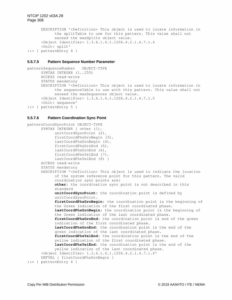
NTCIP 1202 v03A.28 Page 308
Copy Per MIB Distribution Permission © 2019 AASHTO / ITE / NEMA
DESCRIPTION "<Definition> This object is used to locate information in the splitTable to use for this pattern. This value shall not exceed the maxSplits object value.
<Object Identifier> 1.3.6.1.4.1.1206.4.2.1.4.7.1.4 <Unit> split"
::= { patternEntry 4 }
5.5.7.5 Pattern Sequence Number Parameter patternSequenceNumber OBJECT-TYPE
SYNTAX INTEGER (1..255) ACCESS read-write STATUS mandatory DESCRIPTION "<Definition> This object is used to locate information in
the sequenceTable to use with this pattern. This value shall not exceed the maxSequences object value.
<Object Identifier> 1.3.6.1.4.1.1206.4.2.1.4.7.1.5 <Unit> sequence"
::= { patternEntry 5 }
5.5.7.6 Pattern Coordination Sync Point patternCoordSyncPoint OBJECT-TYPE
SYNTAX INTEGER { other (1), unitCoordSyncPoint (2),
firstCoordPhsGrnBegin (3), lastCoordPhsGrnBegin (4), firstCoordPhsGrnEnd (5), lastCoordPhsGrnEnd (6), firstCoordPhsYelEnd (7), lastCoordPhsYelEnd (8) }
ACCESS read-write STATUS mandatory DESCRIPTION "<Definition> This object is used to indicate the location
of the system reference point for this pattern. The valid coordination sync points are: other: the coordination sync point is not described in this standard unitCoordSyncPoint: the coordination point is defined by unitCoordSyncPoint. firstCoordPhsGrnBegin: the coordination point is the beginning of the Green indication of the first coordinated phase. lastCoordPhsGrnBegin: the coordination point is the beginning of the Green indication of the last coordinated phase. firstCoordPhsGrnEnd: the coordination point is end of the green indication of the first coordinated phase. lastCoordPhsGrnEnd: the coordination point is the end of the green indication of the last coordinated phase. firstCoordPhsYelEnd: the coordination point is the end of the yellow indication of the first coordinated phase. lastCoordPhsYelEnd: the coordination point is the end of the yellow indication of the last coordinated phase.
<Object Identifier> 1.3.6.1.4.1.1206.4.2.1.4.7.1.6" DEFVAL { firstCoordPhsGrnBegin }
::= { patternEntry 6 }

NTCIP 1202 v03A.28 Page 309
© 2019 AASHTO / ITE / NEMA Copy Per MIB Distribution Permission
5.5.7.7 Pattern Options patternOptions OBJECT-TYPE
SYNTAX INTEGER { other (1), coordMaximumMode (2),
maxInhibit (3), maximum1 (4), maximum2 (5), maximum3 (6) }
ACCESS read-write STATUS mandatory DESCRIPTION "<Definition> This object represents the maximum mode to be
used for the pattern. The valid maximum modes are: other: the maximum mode is determined by some other mechanism not defined in this standard. coordMaximumMode: use the maximum mode defined by the coordMaximumMode object. maxInhibit: the internal maximum timing shall be inhibited while coordination is running this pattern. maximum1: the internal Maximum 1 Timing shall be effective while coordination is running this pattern. maximum2: the internal Maximum 2 Timing shall be effective while coordination is running this pattern. maximum3: the internal Maximum 3 Timing shall be effective while coordination is running this pattern.
<Object Identifier> 1.3.6.1.4.1.1206.4.2.1.4.7.1.7" ::= { patternEntry 7 }
5.5.7.8 Pattern Enabled Lanes patternSpatEnabledLanes OBJECT-TYPE
SYNTAX OCTET STRING ACCESS read-write STATUS mandatory DESCRIPTION "<Definition> Each octet in this octet string represents
the index of the lanes (mapLaneIndex) that are activated for the current MAP plan in effect(xxxx).
Each indexed lane should have its revocable Lane bit set (Bit 0 set to (1) in the mapLaneAttribute object).
<Object Identifier> 1.3.6.1.4.1.1206.4.2.1.4.7.1.8" ::= { patternEntry 8 }
5.5.8 Maximum Splits maxSplits OBJECT-TYPE
SYNTAX INTEGER (1..255) ACCESS read-only STATUS mandatory DESCRIPTION "<Definition> The maximum number of Split Plans this
Actuated Controller Unit supports. This object indicates how many Split plans are in the splitTable object.
<Object Identifier> 1.3.6.1.4.1.1206.4.2.1.4.8 <Unit> split"
::= { coord 8 }
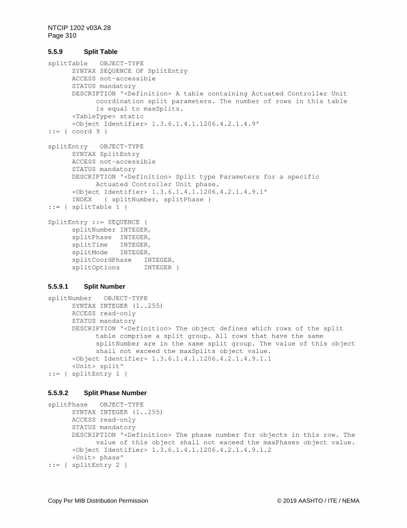
NTCIP 1202 v03A.28 Page 310
Copy Per MIB Distribution Permission © 2019 AASHTO / ITE / NEMA
5.5.9 Split Table splitTable OBJECT-TYPE
SYNTAX SEQUENCE OF SplitEntry ACCESS not-accessible STATUS mandatory DESCRIPTION "<Definition> A table containing Actuated Controller Unit
coordination split parameters. The number of rows in this table is equal to maxSplits.
<TableType> static <Object Identifier> 1.3.6.1.4.1.1206.4.2.1.4.9"
::= { coord 9 } splitEntry OBJECT-TYPE
SYNTAX SplitEntry ACCESS not-accessible STATUS mandatory DESCRIPTION "<Definition> Split type Parameters for a specific
Actuated Controller Unit phase. <Object Identifier> 1.3.6.1.4.1.1206.4.2.1.4.9.1" INDEX { splitNumber, splitPhase }
::= { splitTable 1 } SplitEntry ::= SEQUENCE {
splitNumber INTEGER, splitPhase INTEGER, splitTime INTEGER, splitMode INTEGER, splitCoordPhase INTEGER, splitOptions INTEGER }
5.5.9.1 Split Number splitNumber OBJECT-TYPE
SYNTAX INTEGER (1..255) ACCESS read-only STATUS mandatory DESCRIPTION "<Definition> The object defines which rows of the split
table comprise a split group. All rows that have the same splitNumber are in the same split group. The value of this object shall not exceed the maxSplits object value.
<Object Identifier> 1.3.6.1.4.1.1206.4.2.1.4.9.1.1 <Unit> split"
::= { splitEntry 1 }
5.5.9.2 Split Phase Number splitPhase OBJECT-TYPE
SYNTAX INTEGER (1..255) ACCESS read-only STATUS mandatory DESCRIPTION "<Definition> The phase number for objects in this row. The
value of this object shall not exceed the maxPhases object value. <Object Identifier> 1.3.6.1.4.1.1206.4.2.1.4.9.1.2 <Unit> phase"
::= { splitEntry 2 }

NTCIP 1202 v03A.28 Page 311
© 2019 AASHTO / ITE / NEMA Copy Per MIB Distribution Permission
5.5.9.3 Split Time Parameter splitTime OBJECT-TYPE
SYNTAX INTEGER (0..255) ACCESS read-write STATUS mandatory DESCRIPTION "<Definition> The time in seconds the splitPhase is allowed
to receive (i.e. before a Force Off is applied) when constant demands exist on all phases. In floating coordForceMode, this is always the maximum time a non-coordinated phase is allowed to receive. In fixed coordForceMode, the actual allowed time may be longer if a previous phase gapped out.
The splitTime includes all phase clearance times for the associated phase. The split time shall be longer than the sum of the phase minimum service requirements for the phase. When the time is NOT adequate to service the minimum service requirements of the phase, Free Mode shall be the result. The minimum requirements of a phase with a not-actuated ped include Minimum Green, Walk, Pedestrian Clear, Yellow Clearance, and Red Clearance; the minimum requirements of a phase with an actuated pedestrian include Minimum Green, Yellow Clearance, and Red Clearance.
If the cycleTime entry of the associated patternTable entry is
zero (i.e. the device is in Free Mode), then the value of this object shall be applied, if non-zero, as a maximum time for the associated phase.
If the critical path through the phase diagram is less than the cycleTime entry of the associated patternTable entry, all extra time is allotted to the coordination phase in each ring.
If the critical path through the phase diagram is greater than the cycleTime entry of the associated patternTable entry (and the cycleTime is not zero) the device shall operate in the Free Mode.
While the Free Mode condition exists, the Local Override bit of shortAlarm shall be set to one (1).
<Object Identifier> 1.3.6.1.4.1.1206.4.2.1.4.9.1.3 <Unit> second" REFERENCE "NEMA TS 2 Clause 3.6.2.1.2"
::= { splitEntry 3 }
5.5.9.4 Split Mode Parameter splitMode OBJECT-TYPE
SYNTAX INTEGER { other(1), none (2), minimumVehicleRecall (3), maximumVehicleRecall (4), pedestrianRecall (5), maximumVehicleAndPedestrianRecall (6), phaseOmitted (7), nonActuated (8) }
ACCESS read-write STATUS mandatory

NTCIP 1202 v03A.28 Page 312
Copy Per MIB Distribution Permission © 2019 AASHTO / ITE / NEMA
DESCRIPTION "<Definition> This object defines operational characteristics of the phase. The following options are available: other: the operation is not specified in this standard none: no split mode control. minimumVehicleRecall: this phase operates with a minimum vehicle
recall. maximumVehicleRecall: this phase operates with a maximum vehicle
recall. This value shall also be used for bicycle phase recalls and transit phase recalls.
pedestrianRecall: this phase operates with a pedestrian recall. maximumVehicleAndPedestrianRecall: this phase operates with a
maximum vehicle & pedestrian recall. phaseOmitted: this phase is omitted. nonActuated: this phase operates with a fixed split time.
<Object Identifier> 1.3.6.1.4.1.1206.4.2.1.4.9.1.4" ::= { splitEntry 4 }
5.5.9.5 Split Coordinated Phase splitCoordPhase OBJECT-TYPE
SYNTAX INTEGER (0..1) ACCESS read-write STATUS mandatory DESCRIPTION "<Definition> To select the associated phase as a
coordinated phase this object shall be set to TRUE (non zero). <Object Identifier> 1.3.6.1.4.1.1206.4.2.1.4.9.1.5"
::= { splitEntry 5 }
5.5.9.6 Split Options splitOptions OBJECT-TYPE
SYNTAX INTEGER (0..255) ACCESS read-write STATUS mandatory DESCRIPTION "<Definition> Optional split functions (0 = False/Disabled,
1 = True/Enabled). Bit 7: Reserved
Bit 6: Reserved Bit 5: Reserved Bit 4: Reserved Bit 3: Reserved Bit 2: Reserved Bit 1: Reserved Bit 0: Transition Phase Omit - To allow the associated phase to be omitted during coord Correction Mode (transitions), this object shall be set to TRUE (1). If the associated phase is not allowed to be omitted, this object shall be set to FALSE (0). A SET of a 'reserved' bit to a value other than zero (0) shall return a badValue(3) error.
<Object Identifier> 1.3.6.1.4.1.1206.4.2.1.4.9.1.6" ::= { splitEntry 6 }

NTCIP 1202 v03A.28 Page 313
© 2019 AASHTO / ITE / NEMA Copy Per MIB Distribution Permission
5.5.10 Coordination Pattern Status coordPatternStatus OBJECT-TYPE
SYNTAX INTEGER (0..255) ACCESS read-only STATUS mandatory DESCRIPTION "<Definition> This object defines the running coordination
pattern/mode in the device. The possible values are: Value Description 0 Not used 1-253 Pattern - indicates the currently running pattern 254 Free - indicates Free operation without coordination. 255 Flash - indicates Automatic Flash without coordination.
<Object Identifier> 1.3.6.1.4.1.1206.4.2.1.4.10" ::= { coord 10 }
5.5.11 Local Free Status localFreeStatus OBJECT-TYPE
SYNTAX INTEGER { other(1), notFree(2), commandFree(3), transitionFree(4), inputFree(5), coordFree(6), badPlan(7), badCycleTime(8), splitOverrun (9), invalidOffset (10), failed(11) } ACCESS read-only STATUS mandatory DESCRIPTION "<Definition> The Free modes: other: Some other condition has caused the device to run in free
mode. notFree: The unit is not running in free mode. commandFree: the current pattern command is the Free mode
pattern. transitionFree: the CU has a pattern command but is cycling to a
point to begin coordination. inputFree: one of the CU inputs cause it to not respond to
coordination. coordFree: the CU programming for the called pattern is to run
Free. badPlan: Free - the called pattern is invalid. badCycleTime: the pattern cycle time is less than adequate to
service the minimum requirements of all phases. splitOverrun: Free - the sum of the critical path splitTime’s
exceed the programmed patternCycleTime value. invalidOffset: Free - reserved / not used failed: cycling diagnostics have called for Free.
An ASC may provide diagnostics beyond those stated herein. Therefore, for a set of given bad data, the free status between devices may be inconsistent.
<Object Identifier> 1.3.6.1.4.1.1206.4.2.1.4.11" ::= { coord 11 }

NTCIP 1202 v03A.28 Page 314
Copy Per MIB Distribution Permission © 2019 AASHTO / ITE / NEMA
5.5.12 Coordination Cycle Status coordCycleStatus OBJECT-TYPE
SYNTAX INTEGER (0..510) ACCESS read-only STATUS mandatory DESCRIPTION "<Definition> The Coord Cycle Status represents the current
position in the local coord cycle of the running pattern (0 to 510 sec). This value normally counts down from patternCycleTime to Zero. This value may exceed the patternCycleTime during a coord cycle with offset correction (patternCycleTime + correction).
<Object Identifier> 1.3.6.1.4.1.1206.4.2.1.4.12 <Unit> second"
::= { coord 12 }
5.5.13 Coordination Sync Status coordSyncStatus OBJECT-TYPE
SYNTAX INTEGER (0..510) ACCESS read-only STATUS mandatory DESCRIPTION "<Definition> The Coord Sync Status represents the time
since the system reference point for the running pattern (0 to 510 sec). This value normally counts up from Zero to the next system reference point (patternCycleTime). This value may exceed the patternCycleTime during a coord cycle in which the system reference point has changed.
<Object Identifier> 1.3.6.1.4.1.1206.4.2.1.4.13 <Unit> second"
::= { coord 13 }
5.5.14 System Pattern Control systemPatternControl OBJECT-TYPE
SYNTAX INTEGER (0..255) ACCESS read-write STATUS mandatory DESCRIPTION "<Definition> This object is used to establish the Called
System Pattern/Mode for the device. The possible values are: Value DESCRIPTION 0 Standby - the system relinquishes control of the device. 1-253 Pattern - these values indicate the system commanded pattern 254 Free - this value indicates a call for Free 255 Flash - this value indicates a call for Automatic Flash If an unsupported / invalid pattern is called, Free shall be the operational mode. The device shall reset this object to ZERO when in BACKUP Mode. A write to this object shall reset the Backup timer to ZERO (see unitBackupTime).
<Object Identifier> 1.3.6.1.4.1.1206.4.2.1.4.14" ::= { coord 14 }
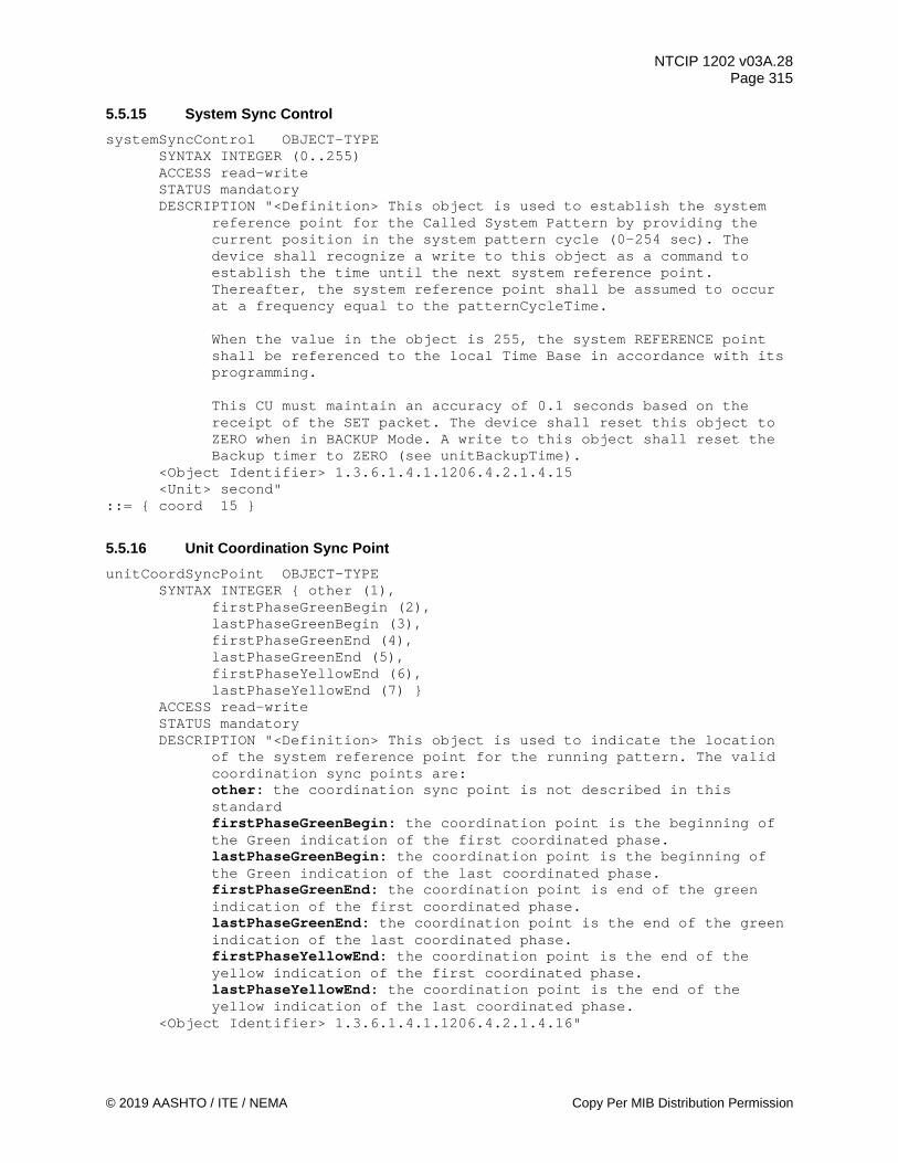
NTCIP 1202 v03A.28 Page 315
© 2019 AASHTO / ITE / NEMA Copy Per MIB Distribution Permission
5.5.15 System Sync Control systemSyncControl OBJECT-TYPE
SYNTAX INTEGER (0..255) ACCESS read-write STATUS mandatory DESCRIPTION "<Definition> This object is used to establish the system
reference point for the Called System Pattern by providing the current position in the system pattern cycle (0-254 sec). The device shall recognize a write to this object as a command to establish the time until the next system reference point. Thereafter, the system reference point shall be assumed to occur at a frequency equal to the patternCycleTime.
When the value in the object is 255, the system REFERENCE point
shall be referenced to the local Time Base in accordance with its programming.
This CU must maintain an accuracy of 0.1 seconds based on the receipt of the SET packet. The device shall reset this object to ZERO when in BACKUP Mode. A write to this object shall reset the Backup timer to ZERO (see unitBackupTime).
<Object Identifier> 1.3.6.1.4.1.1206.4.2.1.4.15 <Unit> second"
::= { coord 15 }
5.5.16 Unit Coordination Sync Point unitCoordSyncPoint OBJECT-TYPE
SYNTAX INTEGER { other (1), firstPhaseGreenBegin (2), lastPhaseGreenBegin (3), firstPhaseGreenEnd (4), lastPhaseGreenEnd (5), firstPhaseYellowEnd (6), lastPhaseYellowEnd (7) }
ACCESS read-write STATUS mandatory DESCRIPTION "<Definition> This object is used to indicate the location
of the system reference point for the running pattern. The valid coordination sync points are: other: the coordination sync point is not described in this standard firstPhaseGreenBegin: the coordination point is the beginning of the Green indication of the first coordinated phase. lastPhaseGreenBegin: the coordination point is the beginning of the Green indication of the last coordinated phase. firstPhaseGreenEnd: the coordination point is end of the green indication of the first coordinated phase. lastPhaseGreenEnd: the coordination point is the end of the green indication of the last coordinated phase. firstPhaseYellowEnd: the coordination point is the end of the yellow indication of the first coordinated phase. lastPhaseYellowEnd: the coordination point is the end of the yellow indication of the last coordinated phase.
<Object Identifier> 1.3.6.1.4.1.1206.4.2.1.4.16"

NTCIP 1202 v03A.28 Page 316
Copy Per MIB Distribution Permission © 2019 AASHTO / ITE / NEMA
DEFVAL { firstPhaseGreenBegin } ::= { coord 16 }
5.6 Time Base Parameters timebaseAsc OBJECT IDENTIFIER ::= { asc 5 } -- This object is an identifier used to group all objects for -- support of timebase functions. If a device implements timebase -- functions then these objects shall be supported.
5.6.1 Time Base Pattern Sync Parameter timebaseAscPatternSync OBJECT-TYPE
SYNTAX INTEGER (0..65535) ACCESS read-write STATUS mandatory DESCRIPTION "<Definition> Pattern Sync Reference in minutes past
midnight. When the value is 65535, the controller unit shall use the Action time as the Sync Reference for that pattern. Action time is the hour and minute associated with the active dayPlanEventNumber (as defined in NTCIP 1201).
<Object Identifier> 1.3.6.1.4.1.1206.4.2.1.5.1 <Unit> minute" REFERENCE "NEMA TS 2 Clause 3.8.2"
::= { timebaseAsc 1 }
5.6.2 Maximum Time Base Actions maxTimebaseAscActions OBJECT-TYPE
SYNTAX INTEGER (1..255) ACCESS read-only STATUS mandatory DESCRIPTION "<Definition> The Maximum Number of Actions this device
supports. This object indicates the maximum rows which shall appear in the timebaseAscActionTable object.
<Object Identifier> 1.3.6.1.4.1.1206.4.2.1.5.2 <Unit> action"
::= { timebaseAsc 2 }
5.6.3 Time Base Asc Action Table timebaseAscActionTable OBJECT-TYPE
SYNTAX SEQUENCE OF TimebaseAscActionEntry ACCESS not-accessible STATUS mandatory DESCRIPTION "<Definition> A table containing Actuated Controller Unit
Time Base action parameters. The number of rows in this table is equal to the maxTimebaseAscActions object.
<TableType> static <Object Identifier> 1.3.6.1.4.1.1206.4.2.1.5.3"
::= { timebaseAsc 3 } timebaseAscActionEntry OBJECT-TYPE
SYNTAX TimebaseAscActionEntry

NTCIP 1202 v03A.28 Page 317
© 2019 AASHTO / ITE / NEMA Copy Per MIB Distribution Permission
ACCESS not-accessible STATUS mandatory DESCRIPTION "<Definition> Action Parameters for a Actuated Controller
Unit Time Base Program. <Object Identifier> 1.3.6.1.4.1.1206.4.2.1.5.3.1" INDEX { timebaseAscActionNumber }
::= { timebaseAscActionTable 1 } TimebaseAscActionEntry ::= SEQUENCE {
timebaseAscActionNumber INTEGER, timebaseAscPattern INTEGER, timebaseAscAuxiliaryFunction INTEGER, timebaseAscSpecialFunction INTEGER }
5.6.3.1 Time Base Action Number timebaseAscActionNumber OBJECT-TYPE
SYNTAX INTEGER (1..255) ACCESS read-only STATUS mandatory DESCRIPTION "<Definition> The time base Action number for objects in
this row. This value shall not exceed the maxTimebaseAscActions object value. This object may be defined as a dayPlanActionOID (as defined in NTCIP 1201).
<Object Identifier> 1.3.6.1.4.1.1206.4.2.1.5.3.1.1 <Unit> action"
::= { timebaseAscActionEntry 1 }
5.6.3.2 Time Base Action Pattern Parameter timebaseAscPattern OBJECT-TYPE
SYNTAX INTEGER (0..255) ACCESS read-write STATUS mandatory DESCRIPTION "<Definition> The Pattern that shall be active when this
Action is active. The value shall not exceed the value of maxPatterns, except for flash or free. A pattern of zero indicates that no pattern is being selected. A pattern = 0 relinquishes control to entity of a lower priority than timebase and allows that entity to control (i.e., interconnect if available).
<Object Identifier> 1.3.6.1.4.1.1206.4.2.1.5.3.1.2 <Unit> pattern"
::= { timebaseAscActionEntry 2 }
5.6.3.3 Time Base Action Auxiliary Function Parameter timebaseAscAuxiliaryFunction OBJECT-TYPE
SYNTAX INTEGER (0..255) ACCESS read-write STATUS mandatory DESCRIPTION "<Definition> The Auxiliary functions that shall be active
when this Action is active. Bit 7: Reserved Bit 6: Reserved Bit 5: Reserved

NTCIP 1202 v03A.28 Page 318
Copy Per MIB Distribution Permission © 2019 AASHTO / ITE / NEMA
Bit 4: Reserved Bit 3: Dimming enabled if set (non-zero), disabled if clear
(zero). For dimming to occur, this control AND ('unitControl' OR a dimming input) must be True.
Bit 2: Auxiliary Function 3 enabled if set (non-zero), disabled if clear (zero).
Bit 1: Auxiliary Function 2 enabled if set (non-zero), disabled if clear (zero).
Bit 0: Auxiliary Function 1 enabled if set (non-zero), disabled if clear (zero).
A SET of a 'reserved' bit to a value other than zero (0) shall return a badValue(3) error.
<Object Identifier> 1.3.6.1.4.1.1206.4.2.1.5.3.1.3" ::= { timebaseAscActionEntry 3 }
5.6.3.4 Time Base Action Special Function Parameter timebaseAscSpecialFunction OBJECT-TYPE
SYNTAX INTEGER (0..255) ACCESS read-write STATUS mandatory DESCRIPTION "<Definition> The Special Functions that shall be active
when this Action is active. Bit 7: Special Function 8 Bit 6: Special Function 7 Bit 5: Special Function 6 Bit 4: Special Function 5 Bit 3: Special Function 4 Bit 2: Special Function 3 Bit 1: Special Function 2 Bit 0: Special Function 1 Bit = 0 - False/Disabled, Bit = 1 - True/Enabled
<Object Identifier> 1.3.6.1.4.1.1206.4.2.1.5.3.1.4" ::= { timebaseAscActionEntry 4 }
5.6.4 Time Base Asc Action Status timebaseAscActionStatus OBJECT-TYPE
SYNTAX INTEGER(0..255) ACCESS read-only STATUS mandatory DESCRIPTION "<Definition> This object indicates the current time base
Action Table row that will be used when the CU is in Time Base operation. A value of zero indicates that no time base Action is selected.
<Object Identifier> 1.3.6.1.4.1.1206.4.2.1.5.4" ::= { timebaseAsc 4 }
5.6.5 Action Plan Command actionPlanControl OBJECT-TYPE
SYNTAX INTEGER (0..255) ACCESS read-write STATUS mandatory DESCRIPTION "<Definition> This object is used to activate a configured
action plan by referencing the Action number
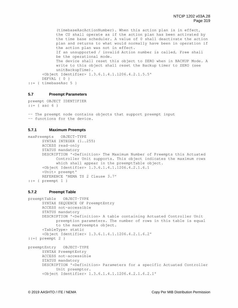
NTCIP 1202 v03A.28 Page 319
© 2019 AASHTO / ITE / NEMA Copy Per MIB Distribution Permission
(timebaseAscActionNumber). When this action plan is in effect, the CU shall operate as if the action plan has been activated by the time base scheduler. A value of 0 shall deactivate the action plan and returns to what would normally have been in operation if the action plan was not in effect. If an unsupported / invalid Action number is called, Free shall be the operational mode.
The device shall reset this object to ZERO when in BACKUP Mode. A write to this object shall reset the Backup timer to ZERO (see unitBackupTime).
<Object Identifier> 1.3.6.1.4.1.1206.4.2.1.5.5" DEFVAL { 0 }
::= { timebaseAsc 5 }
5.7 Preempt Parameters preempt OBJECT IDENTIFIER ::= { asc 6 } -- The preempt node contains objects that support preempt input -- functions for the device.
5.7.1 Maximum Preempts maxPreempts OBJECT-TYPE
SYNTAX INTEGER (1..255) ACCESS read-only STATUS mandatory DESCRIPTION "<Definition> The Maximum Number of Preempts this Actuated
Controller Unit supports. This object indicates the maximum rows which shall appear in the preemptTable object.
<Object Identifier> 1.3.6.1.4.1.1206.4.2.1.6.1 <Unit> preempt" REFERENCE "NEMA TS 2 Clause 3.7"
::= { preempt 1 }
5.7.2 Preempt Table preemptTable OBJECT-TYPE
SYNTAX SEQUENCE OF PreemptEntry ACCESS not-accessible STATUS mandatory DESCRIPTION "<Definition> A table containing Actuated Controller Unit
preemption parameters. The number of rows in this table is equal to the maxPreempts object.
<TableType> static <Object Identifier> 1.3.6.1.4.1.1206.4.2.1.6.2"
::={ preempt 2 } preemptEntry OBJECT-TYPE
SYNTAX PreemptEntry ACCESS not-accessible STATUS mandatory DESCRIPTION "<Definition> Parameters for a specific Actuated Controller
Unit preemptor. <Object Identifier> 1.3.6.1.4.1.1206.4.2.1.6.2.1"

NTCIP 1202 v03A.28 Page 320
Copy Per MIB Distribution Permission © 2019 AASHTO / ITE / NEMA
INDEX { preemptNumber } ::={ preemptTable 1} PreemptEntry ::= SEQUENCE {
preemptNumber INTEGER, preemptControl INTEGER, preemptLink INTEGER, preemptDelay INTEGER, preemptMinimumDuration INTEGER, preemptMinimumGreen INTEGER, preemptMinimumWalk INTEGER, preemptEnterPedClear INTEGER, preemptTrackGreen INTEGER, preemptDwellGreen INTEGER, preemptMaximumPresence INTEGER, preemptTrackPhase OCTET STRING, preemptDwellPhase OCTET STRING, preemptDwellPed OCTET STRING, preemptExitPhase OCTET STRING, preemptState INTEGER, preemptTrackOverlap OCTET STRING, preemptDwellOverlap OCTET STRING, preemptCyclingPhase OCTET STRING, preemptCyclingPed OCTET STRING, preemptCyclingOverlap OCTET STRING, preemptEnterYellowChange INTEGER, preemptEnterRedClear INTEGER, preemptTrackYellowChange INTEGER, preemptTrackRedClear INTEGER, preemptSequenceNumber INTEGER, preemptExitType INTEGER }
5.7.2.1 Preempt Number preemptNumber OBJECT-TYPE
SYNTAX INTEGER (1..255) ACCESS read-only STATUS mandatory DESCRIPTION "<Definition> The preempt number for objects in this row.
The value shall not exceed the maxPreempts object value. When all preemptControl objects have a value where bit 2 = 0, each preemptNumber routine shall be a higher priority and override all preemptNumber routines that have a larger preemptNumber. When a preemptControl object has a value where bit 2 = 1, the next higher preemptNumber becomes of equal priority with the preemptNumber but may still be a higher priority than larger preemptNumbers depending on bit 2 of the relavent preemptControl objects.
<Object Identifier> 1.3.6.1.4.1.1206.4.2.1.6.2.1.1 <Unit> preempt"
::= { preemptEntry 1 }
5.7.2.2 Preempt Control Parameter preemptControl OBJECT-TYPE
SYNTAX INTEGER (0..255)

NTCIP 1202 v03A.28 Page 321
© 2019 AASHTO / ITE / NEMA Copy Per MIB Distribution Permission
ACCESS read-write STATUS mandatory DESCRIPTION "<Definition> Preempt Miscellaneous Control Parameter Mask
(Bit=0: False/Disabled, Bit=1: True/Enabled) as follows: Bit 7: Reserved Bit 6: Reserved Bit 5: All Red Flash - the CU shall enter to all red flash
instead of normal operations when the preemptMaximumPresence is exceeded
Bit 4: Preempt Enable - enables or disables this preemption input. Disabling preempts should be done with extreme caution.
Bit 3: Flash Dwell - the CU shall cause the phases listed in the preemptDwellPhase object to flash Yellow during the Dwell interval. All active phases not listed in preemptDwellPhase shall flash Red. The CU shall cause the overlaps listed in the preemptDwellOverlap object to flash Yellow during the Dwell state. All active overlaps not listed in preemptDwellOverlap shall flash Red. Preempt cycling phase programming is ignored if this bit is set. This control is optional.
Bit 2: Preempt Override preemptNumber + 1 - provide a means to define whether this preempt shall NOT override the next higher numbered Preempt. When set (1) this preempt shall not override the next higher numbered preempt. Lowered numbered preempts override higher numbered preempts. For example, 1 overrides 3, and the only way to get 3 equal to 1, is to set both 1 and 2 to NOT override the next higher numbered preempt. This parameter shall be ignored when preemptNumber equals maxPreempts.
Bit 1: Preempt Override Flash - provide a means to define whether this preempt shall NOT override Automatic Flash. When set (1) this preempt shall not override Automatic Flash.
Bit 0: Non-Locking Memory - provide a means to enable an operation which does not require detector memory. When set (1) a preempt sequence shall not occur if the preempt input terminates prior to expiration of the preemptDelay time.
A SET of a 'reserved' bit to a value other than zero (0) shall return a badValue(3) error. Support for Preempt Enable and All Red Flash added in NTCIP 1202 v03.
<Object Identifier> 1.3.6.1.4.1.1206.4.2.1.6.2.1.2" REFERENCE "NEMA TS 2 Clause 3.7.2.1 and 3.7.2.2" DEFVAL { 0 }
::= { preemptEntry 2 }
5.7.2.3 Preempt Link Parameter preemptLink OBJECT-TYPE
SYNTAX INTEGER (0..255) ACCESS read-write STATUS mandatory DESCRIPTION "<Definition> This object provides a means to define a
higher priority preempt to be combined (linked) with this preempt. At the end of preemptDwellGreen, the linked preempt shall receive an automatic call that shall be maintained as long as the demand for this preempt is active. Any value that is not a
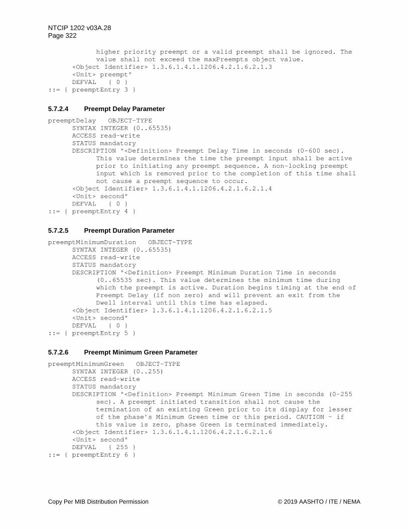
NTCIP 1202 v03A.28 Page 322
Copy Per MIB Distribution Permission © 2019 AASHTO / ITE / NEMA
higher priority preempt or a valid preempt shall be ignored. The value shall not exceed the maxPreempts object value.
<Object Identifier> 1.3.6.1.4.1.1206.4.2.1.6.2.1.3 <Unit> preempt" DEFVAL { 0 }
::= { preemptEntry 3 }
5.7.2.4 Preempt Delay Parameter preemptDelay OBJECT-TYPE
SYNTAX INTEGER (0..65535) ACCESS read-write STATUS mandatory DESCRIPTION "<Definition> Preempt Delay Time in seconds (0-600 sec).
This value determines the time the preempt input shall be active prior to initiating any preempt sequence. A non-locking preempt input which is removed prior to the completion of this time shall not cause a preempt sequence to occur.
<Object Identifier> 1.3.6.1.4.1.1206.4.2.1.6.2.1.4 <Unit> second" DEFVAL { 0 }
::= { preemptEntry 4 }
5.7.2.5 Preempt Duration Parameter preemptMinimumDuration OBJECT-TYPE
SYNTAX INTEGER (0..65535) ACCESS read-write STATUS mandatory DESCRIPTION "<Definition> Preempt Minimum Duration Time in seconds
(0..65535 sec). This value determines the minimum time during which the preempt is active. Duration begins timing at the end of Preempt Delay (if non zero) and will prevent an exit from the Dwell interval until this time has elapsed.
<Object Identifier> 1.3.6.1.4.1.1206.4.2.1.6.2.1.5 <Unit> second" DEFVAL { 0 }
::= { preemptEntry 5 }
5.7.2.6 Preempt Minimum Green Parameter preemptMinimumGreen OBJECT-TYPE
SYNTAX INTEGER (0..255) ACCESS read-write STATUS mandatory DESCRIPTION "<Definition> Preempt Minimum Green Time in seconds (0-255
sec). A preempt initiated transition shall not cause the termination of an existing Green prior to its display for lesser of the phase’s Minimum Green time or this period. CAUTION - if this value is zero, phase Green is terminated immediately.
<Object Identifier> 1.3.6.1.4.1.1206.4.2.1.6.2.1.6 <Unit> second" DEFVAL { 255 }
::= { preemptEntry 6 }

NTCIP 1202 v03A.28 Page 323
© 2019 AASHTO / ITE / NEMA Copy Per MIB Distribution Permission
5.7.2.7 Preempt Minimum Walk Parameter preemptMinimumWalk OBJECT-TYPE
SYNTAX INTEGER (0..255) ACCESS read-write STATUS mandatory DESCRIPTION "<Definition> Preempt Minimum Walk Time in seconds (0-255
sec). A preempt initiated transition shall not cause the termination of an existing Walk prior to its display for the lesser of the phase’s Walk time or this period. CAUTION - if this value is zero, phase Walk is terminated immediately.
<Object Identifier> 1.3.6.1.4.1.1206.4.2.1.6.2.1.7 <Unit> second" DEFVAL { 255 }
::= { preemptEntry 7 }
5.7.2.8 Preempt Enter Pedestrian Clear Parameter preemptEnterPedClear OBJECT-TYPE
SYNTAX INTEGER (0..255) ACCESS read-write STATUS mandatory DESCRIPTION "<Definition> Enter Ped ClearTime in seconds (0-255 sec).
This parameter controls the ped clear timing for a normal Walk signal terminated by a preempt initiated transition. A preempt initiated transition shall not cause the termination of a Pedestrian Clearance prior to its display for the lesser of the phase’s Pedestrian Clearance time or this period. CAUTION - if this value is zero, phase Ped Clear is terminated immediately.
<Object Identifier> 1.3.6.1.4.1.1206.4.2.1.6.2.1.8 <Unit> second" DEFVAL { 255 }
::= { preemptEntry 8 }
5.7.2.9 Preempt Track Green Parameter preemptTrackGreen OBJECT-TYPE
SYNTAX INTEGER (0..255) ACCESS read-write STATUS mandatory DESCRIPTION "<Definition> Track Clear Green Time in seconds (0-255
sec). This parameter controls the green timing for the track clearance movement. Track Clear phase(s) are enabled in the preemptTrackPhase object. If this value is zero, the track clearance movement is omitted, regardless of preemptTrackPhase programming.
<Object Identifier> 1.3.6.1.4.1.1206.4.2.1.6.2.1.9 <Unit> second" DEFVAL { 0 }
::= { preemptEntry 9 }
5.7.2.10 Preempt Minimum Dwell Parameter preemptDwellGreen OBJECT-TYPE
SYNTAX INTEGER (0..255) ACCESS read-write STATUS mandatory

NTCIP 1202 v03A.28 Page 324
Copy Per MIB Distribution Permission © 2019 AASHTO / ITE / NEMA
DESCRIPTION "<Definition> Minimum Dwell interval in seconds (1-255 sec). This parameter controls the minimum timing for the dwell interval. Phase(s) active during the Dwell interval are enabled in preemptDwellPhase and preemptCyclingPhase objects. The Dwell interval shall not terminate prior to the completion of preemptMinimumDuration, preemptDwellGreen (this object), and the call is no longer present.
<Object Identifier> 1.3.6.1.4.1.1206.4.2.1.6.2.1.10 <Unit> second" DEFVAL { 10 }
::= { preemptEntry 10 }
5.7.2.11 Preempt Maximum Presence Parameter preemptMaximumPresence OBJECT-TYPE
SYNTAX INTEGER (0..65535) ACCESS read-write STATUS mandatory DESCRIPTION "<Definition> Preempt Maximum Presence time in seconds (0-
65535 sec). This value determines the maximum time which a preempt call may remain active and be considered valid. When the preempt call has been active for this time period, the CU shall return to normal operation. This preempt call shall be considered invalid until such time as a change in state occurs (no longer active). When set to zero the preempt maximum presence time is disabled.
<Object Identifier> 1.3.6.1.4.1.1206.4.2.1.6.2.1.11 <Unit> second" DEFVAL { 0 }
::= { preemptEntry 11 }
5.7.2.12 Preempt Track Phase Parameter preemptTrackPhase OBJECT-TYPE
SYNTAX OCTET STRING ACCESS read-write STATUS mandatory DESCRIPTION "<Definition> Each octet within the octet string contains a
phaseNumber(binary value) that shall be active during the Preempt Track Clear intervals. The values of phaseNumber used here shall not exceed maxPhases or violate the Consistency Checks defined in Section 4.3.2.
<Object Identifier> 1.3.6.1.4.1.1206.4.2.1.6.2.1.12" DEFVAL { "" }
::= { preemptEntry 12 }
5.7.2.13 Preempt Dwell Phase Parameter preemptDwellPhase OBJECT-TYPE
SYNTAX OCTET STRING ACCESS read-write STATUS mandatory DESCRIPTION "<Definition> Each octet within the octet string contains a
phaseNumber (binary value) that specifies the phase(s) to be served in the Preempt Dwell interval. The phase(s) defined in preemptCyclingPhase shall occur after those defined herein. The
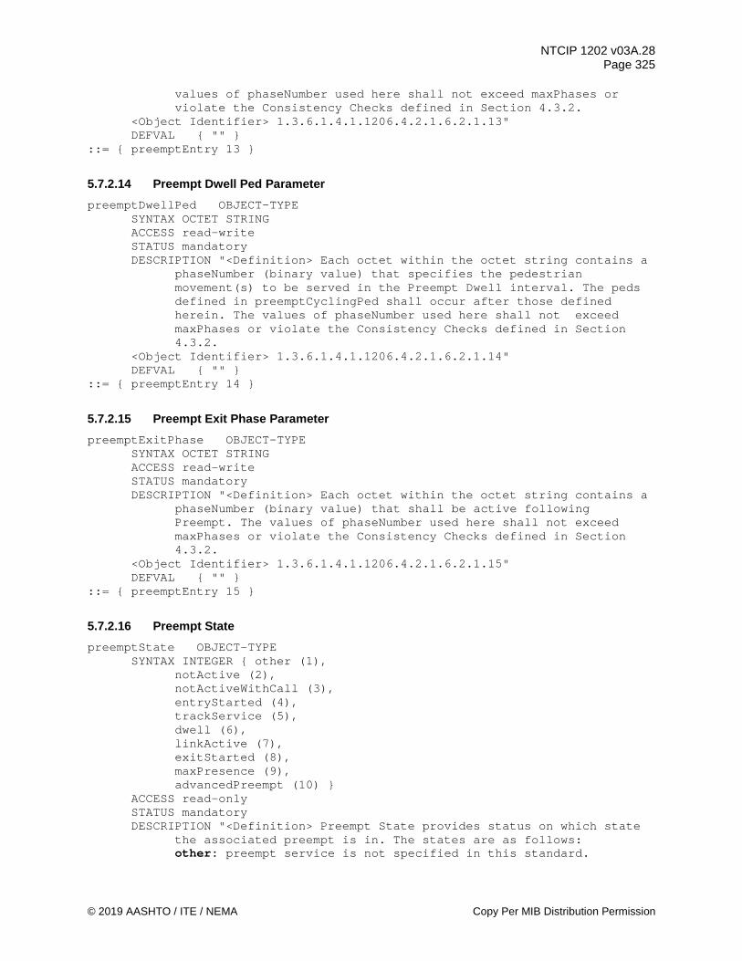
NTCIP 1202 v03A.28 Page 325
© 2019 AASHTO / ITE / NEMA Copy Per MIB Distribution Permission
values of phaseNumber used here shall not exceed maxPhases or violate the Consistency Checks defined in Section 4.3.2.
<Object Identifier> 1.3.6.1.4.1.1206.4.2.1.6.2.1.13" DEFVAL { "" }
::= { preemptEntry 13 }
5.7.2.14 Preempt Dwell Ped Parameter preemptDwellPed OBJECT-TYPE
SYNTAX OCTET STRING ACCESS read-write STATUS mandatory DESCRIPTION "<Definition> Each octet within the octet string contains a
phaseNumber (binary value) that specifies the pedestrian movement(s) to be served in the Preempt Dwell interval. The peds defined in preemptCyclingPed shall occur after those defined herein. The values of phaseNumber used here shall not exceed maxPhases or violate the Consistency Checks defined in Section 4.3.2.
<Object Identifier> 1.3.6.1.4.1.1206.4.2.1.6.2.1.14" DEFVAL { "" }
::= { preemptEntry 14 }
5.7.2.15 Preempt Exit Phase Parameter preemptExitPhase OBJECT-TYPE
SYNTAX OCTET STRING ACCESS read-write STATUS mandatory DESCRIPTION "<Definition> Each octet within the octet string contains a
phaseNumber (binary value) that shall be active following Preempt. The values of phaseNumber used here shall not exceed maxPhases or violate the Consistency Checks defined in Section 4.3.2.
<Object Identifier> 1.3.6.1.4.1.1206.4.2.1.6.2.1.15" DEFVAL { "" }
::= { preemptEntry 15 }
5.7.2.16 Preempt State preemptState OBJECT-TYPE
SYNTAX INTEGER { other (1), notActive (2), notActiveWithCall (3), entryStarted (4), trackService (5), dwell (6), linkActive (7), exitStarted (8), maxPresence (9), advancedPreempt (10) }
ACCESS read-only STATUS mandatory DESCRIPTION "<Definition> Preempt State provides status on which state
the associated preempt is in. The states are as follows: other: preempt service is not specified in this standard.
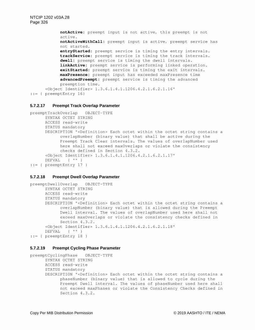
NTCIP 1202 v03A.28 Page 326
Copy Per MIB Distribution Permission © 2019 AASHTO / ITE / NEMA
notActive: preempt input is not active, this preempt is not active. notActiveWithCall: preempt input is active, preempt service has not started. entryStarted: preempt service is timing the entry intervals. trackService: preempt service is timing the track intervals. dwell: preempt service is timing the dwell intervals. linkActive: preempt service is performing linked operation. exitStarted: preempt service is timing the exit intervals. maxPresence: preempt input has exceeded maxPresence time advancedPreempt: preempt service is timing the advanced preemption time.
<Object Identifier> 1.3.6.1.4.1.1206.4.2.1.6.2.1.16" ::= { preemptEntry 16}
5.7.2.17 Preempt Track Overlap Parameter preemptTrackOverlap OBJECT-TYPE
SYNTAX OCTET STRING ACCESS read-write STATUS mandatory DESCRIPTION "<Definition> Each octet within the octet string contains a
overlapNumber (binary value) that shall be active during the Preempt Track Clear intervals. The values of overlapNumber used here shall not exceed maxOverlaps or violate the consistency checks defined in Section 4.3.2.
<Object Identifier> 1.3.6.1.4.1.1206.4.2.1.6.2.1.17" DEFVAL { "" }
::= { preemptEntry 17 }
5.7.2.18 Preempt Dwell Overlap Parameter preemptDwellOverlap OBJECT-TYPE
SYNTAX OCTET STRING ACCESS read-write STATUS mandatory DESCRIPTION "<Definition> Each octet within the octet string contains a
overlapNumber (binary value) that is allowed during the Preempt Dwell interval. The values of overlapNumber used here shall not exceed maxOverlaps or violate the consistency checks defined in Section 4.3.2.
<Object Identifier> 1.3.6.1.4.1.1206.4.2.1.6.2.1.18" DEFVAL { "" }
::= { preemptEntry 18 }
5.7.2.19 Preempt Cycling Phase Parameter preemptCyclingPhase OBJECT-TYPE
SYNTAX OCTET STRING ACCESS read-write STATUS mandatory DESCRIPTION "<Definition> Each octet within the octet string contains a
phaseNumber (binary value) that is allowed to cycle during the Preempt Dwell interval. The values of phaseNumber used here shall not exceed maxPhases or violate the Consistency Checks defined in Section 4.3.2.
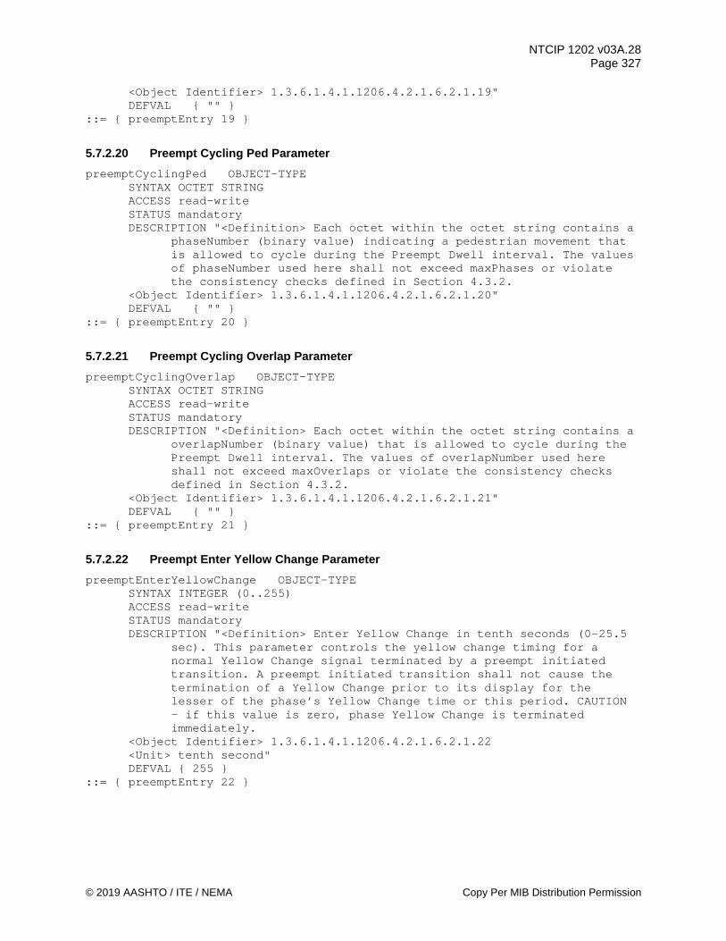
NTCIP 1202 v03A.28 Page 327
© 2019 AASHTO / ITE / NEMA Copy Per MIB Distribution Permission
<Object Identifier> 1.3.6.1.4.1.1206.4.2.1.6.2.1.19" DEFVAL { "" }
::= { preemptEntry 19 }
5.7.2.20 Preempt Cycling Ped Parameter preemptCyclingPed OBJECT-TYPE
SYNTAX OCTET STRING ACCESS read-write STATUS mandatory DESCRIPTION "<Definition> Each octet within the octet string contains a
phaseNumber (binary value) indicating a pedestrian movement that is allowed to cycle during the Preempt Dwell interval. The values of phaseNumber used here shall not exceed maxPhases or violate the consistency checks defined in Section 4.3.2.
<Object Identifier> 1.3.6.1.4.1.1206.4.2.1.6.2.1.20" DEFVAL { "" }
::= { preemptEntry 20 }
5.7.2.21 Preempt Cycling Overlap Parameter preemptCyclingOverlap OBJECT-TYPE
SYNTAX OCTET STRING ACCESS read-write STATUS mandatory DESCRIPTION "<Definition> Each octet within the octet string contains a
overlapNumber (binary value) that is allowed to cycle during the Preempt Dwell interval. The values of overlapNumber used here shall not exceed maxOverlaps or violate the consistency checks defined in Section 4.3.2.
<Object Identifier> 1.3.6.1.4.1.1206.4.2.1.6.2.1.21" DEFVAL { "" }
::= { preemptEntry 21 }
5.7.2.22 Preempt Enter Yellow Change Parameter preemptEnterYellowChange OBJECT-TYPE
SYNTAX INTEGER (0..255) ACCESS read-write STATUS mandatory DESCRIPTION "<Definition> Enter Yellow Change in tenth seconds (0-25.5
sec). This parameter controls the yellow change timing for a normal Yellow Change signal terminated by a preempt initiated transition. A preempt initiated transition shall not cause the termination of a Yellow Change prior to its display for the lesser of the phase’s Yellow Change time or this period. CAUTION - if this value is zero, phase Yellow Change is terminated immediately.
<Object Identifier> 1.3.6.1.4.1.1206.4.2.1.6.2.1.22 <Unit> tenth second" DEFVAL { 255 }
::= { preemptEntry 22 }

NTCIP 1202 v03A.28 Page 328
Copy Per MIB Distribution Permission © 2019 AASHTO / ITE / NEMA
5.7.2.23 Preempt Enter Red Clear Parameter preemptEnterRedClear OBJECT-TYPE
SYNTAX INTEGER (0..255) ACCESS read-write STATUS mandatory DESCRIPTION "<Definition> Enter Red Clear in tenth seconds (0-25.5
sec). This parameter controls the red clearance timing for a normal Red Clear signal terminated by a preempt initiated transition. A preempt initiated transition shall not cause the termination of a Red Clear prior to its display for the lesser of the phase’s Red Clear time or this period. CAUTION - if this value is zero, phase Red Clear is terminated immediately.
<Object Identifier> 1.3.6.1.4.1.1206.4.2.1.6.2.1.23 <Unit> tenth second" DEFVAL { 255 }
::= { preemptEntry 23 }
5.7.2.24 Preempt Track Yellow Change Parameter preemptTrackYellowChange OBJECT-TYPE
SYNTAX INTEGER (0..255) ACCESS read-write STATUS mandatory DESCRIPTION "<Definition> Track Clear Yellow Change time in tenth
seconds (0-25.5 sec). The lesser of the phase’s Yellow Change time or this parameter controls the yellow timing for the track clearance movement. Track clear phase(s) are enabled in the preemptTrackPhase object.
<Object Identifier> 1.3.6.1.4.1.1206.4.2.1.6.2.1.24 <Unit> tenth second" DEFVAL { 255 }
::= { preemptEntry 24 }
5.7.2.25 Preempt Track Red Clear Parameter preemptTrackRedClear OBJECT-TYPE
SYNTAX INTEGER (0..255) ACCESS read-write STATUS mandatory DESCRIPTION "<Definition> Track Clear Red Clear time in tenth seconds
(0-25.5 sec). The lesser of the phase’s Red Clear time or this parameter controls the Red Clear timing for the track clearance movement. Track clear phase(s) are enabled in the preemptTrackPhase object.
<Object Identifier> 1.3.6.1.4.1.1206.4.2.1.6.2.1.25 <Unit> tenth second" DEFVAL { 255 }
::= { preemptEntry 25 }
5.7.2.26 Preempt Sequence Number preemptSequenceNumber OBJECT-TYPE
SYNTAX INTEGER (1..255) ACCESS read-write STATUS mandatory

NTCIP 1202 v03A.28 Page 329
© 2019 AASHTO / ITE / NEMA Copy Per MIB Distribution Permission
DESCRIPTION "<Definition> This object is used to configure the sequenceNumber to run during the preempt's dwell duration. This value shall not exceed the maxSequences object value.
<Object Identifier> 1.3.6.1.4.1.1206.4.2.1.6.2.1.26 <Unit> sequence"
::= { preemptEntry 26 }
5.7.2.27 Preempt Exit Type preemptExitType OBJECT-TYPE
SYNTAX INTEGER { exitPhases (1), queueDelayRecovery (2), shortService (3),
exitCoord (4)} ACCESS read-write STATUS mandatory DESCRIPTION "<Definition> This object defines the exit strategy (type)
to be used following the end of the preempt. The exit types are as follows: exitPhases: the CU immediately enters the exit phases to be
active as configured queueDelayRecovery: the CU immediately enters the phase with the
highest demand or longest wait time shortService: the CU immediately enters the first short service
phase. The first short service phase is a phase where only the preempt minimum green time was serviced during the advanced preemption time or the right-of-way transfer time
exitCoord: the CU immediately returns to the place in the coordinated cycle where the ASC would have been if there was no preempt
<Object Identifier> 1.3.6.1.4.1.1206.4.2.1.6.2.1.27" ::= { preemptEntry 28 }
5.7.3 Preempt Control Table preemptControlTable OBJECT-TYPE
SYNTAX SEQUENCE OF PreemptControlEntry ACCESS not-accessible STATUS mandatory DESCRIPTION "<Definition> This table contains the control objects that
allow the preempts to be activated remotely. There shall be one control object for each preempt input supported by the device. The number of rows in this table shall be equal to maxPreempts.
<TableType> static <Object Identifier> 1.3.6.1.4.1.1206.4.2.1.6.3"
::= { preempt 3 } preemptControlEntry OBJECT-TYPE
SYNTAX PreemptControlEntry ACCESS not-accessible STATUS mandatory DESCRIPTION "<Definition> Control objects for each preempt input. These
objects allow the system to activate preempt functions remotely. <Object Identifier> 1.3.6.1.4.1.1206.4.2.1.6.3.1" INDEX { preemptControlNumber }
::= { preemptControlTable 1 }

NTCIP 1202 v03A.28 Page 330
Copy Per MIB Distribution Permission © 2019 AASHTO / ITE / NEMA
PreemptControlEntry ::= SEQUENCE { preemptControlNumber INTEGER, preemptControlState INTEGER }
5.7.3.1 Preempt Control Number preemptControlNumber OBJECT-TYPE
SYNTAX INTEGER (1..255) ACCESS read-only STATUS mandatory DESCRIPTION "<Definition> This object shall indicate the preempt input
number controlled by the associated preemptControlState object in this row.
<Object Identifier> 1.3.6.1.4.1.1206.4.2.1.6.3.1.1 <Unit> preempt"
::= { preemptControlEntry 1 }
5.7.3.2 Preempt Control State preemptControlState OBJECT-TYPE
SYNTAX INTEGER (0..1) ACCESS read-write STATUS mandatory DESCRIPTION "<Definition> This object when set to ON (one) shall cause
the associated preempt actions to occur unless the actions have already been started by the physical preempt input. The preempt shall remain active as long as this object is ON or the physical preempt input is ON. This object when set to OFF (zero) shall cause the physical preempt input to control the associated preempt actions. The device shall reset this object to ZERO when in BACKUP Mode. A write to this object shall reset the Backup timer to ZERO (see unitBackupTime).
<Object Identifier> 1.3.6.1.4.1.1206.4.2.1.6.3.1.2" ::= { preemptControlEntry 2 }
5.7.4 Preempt Status preemptStatus OBJECT-TYPE
SYNTAX INTEGER (0..255) ACCESS read-only STATUS mandatory DESCRIPTION "<Definition> This object defines the preempt number that
is currently being serviced in the device. <Object Identifier> 1.3.6.1.4.1.1206.4.2.1.6.4"
::= { preempt 4 }
5.7.5 Maximum Preempt Groups maxPreemptGroups OBJECT-TYPE
SYNTAX INTEGER (0..2) ACCESS read-only STATUS mandatory DESCRIPTION "<Definition> The Maximum Number of Preempt Groups (8
Preempt per group) this CU supports. This value is equal to TRUNCATE [(maxPreempts + 7) / 8]. This object indicates the maximum rows which shall appear in the preemptStatusGroupTable.

NTCIP 1202 v03A.28 Page 331
© 2019 AASHTO / ITE / NEMA Copy Per MIB Distribution Permission
<<Object Identifier> 1.3.6.1.4.1.1206.4.2.1.6.5 <Unit> group"
::= { preempt 5 }
5.7.6 Preempt Status Table preemptStatusGroupTable OBJECT-TYPE
SYNTAX SEQUENCE OF PreemptStatusGroupEntry ACCESS not-accessible STATUS mandatory DESCRIPTION "<Definition> A table containing the CU preempt input
signal status in groups of eight Preempts. The number of rows in this table is equal to the maxPreemptGroups object.
<TableType> static <Object Identifier> 1.3.6.1.4.1.1206.4.2.1.6.6"
::= { preempt 6 }
preemptStatusGroupEntry OBJECT-TYPE SYNTAX PreemptStatusGroupEntry ACCESS not-accessible STATUS mandatory DESCRIPTION "<Definition> Preempt input signal status for eight preempt
inputs. <Object Identifier> 1.3.6.1.4.1.1206.4.2.1.6.6.1" INDEX { preemptStatusGroupNumber }
::= { preemptStatusGroupTable 1 } PreemptStatusGroupEntry ::= SEQUENCE {
preemptStatusGroupNumber INTEGER, preemptStatusGroup INTEGER }
5.7.6.1 Preempt Status Group Number preemptStatusGroupNumber OBJECT-TYPE
SYNTAX INTEGER (1..255) ACCESS read-only STATUS mandatory DESCRIPTION "<Definition> The Preempt StatusGroup number for objects in
this row. This value shall not exceed the maxPreemptGroups object value.
<Object Identifier> 1.3.6.1.4.1.1206.4.2.1.6.6.1.1 <Unit> group"
::= { preemptStatusGroupEntry 1 }
5.7.6.2 Preempt Status Group preemptStatusGroup OBJECT-TYPE
SYNTAX INTEGER (0..255) ACCESS read-only STATUS mandatory DESCRIPTION "<Definition> Preempt Input Signal Status Mask, when a,
when a bit = 1, a preempt input signal is detected, and when a bit = 0, no preempt input signal is detected. Bit 7: Preempt # = (preemptStatusGroupNumber * 8) Bit 6: Preempt # = (preemptStatusGroupNumber * 8) - 1 Bit 5: Preempt # = (preemptStatusGroupNumber * 8) - 2
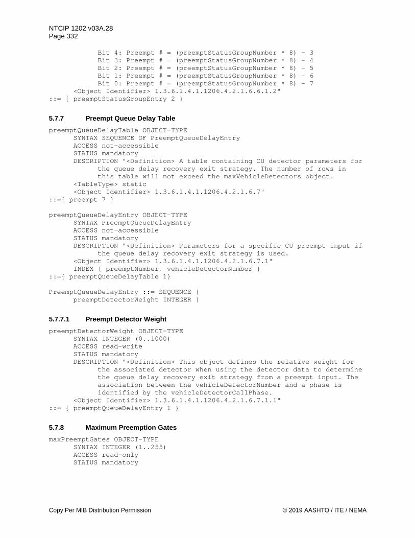
NTCIP 1202 v03A.28 Page 332
Copy Per MIB Distribution Permission © 2019 AASHTO / ITE / NEMA
Bit 4: Preempt # = (preemptStatusGroupNumber * 8) - 3 Bit 3: Preempt # = (preemptStatusGroupNumber * 8) - 4 Bit 2: Preempt # = (preemptStatusGroupNumber * 8) - 5 Bit 1: Preempt # = (preemptStatusGroupNumber * 8) - 6 Bit 0: Preempt # = (preemptStatusGroupNumber * 8) - 7
<Object Identifier> 1.3.6.1.4.1.1206.4.2.1.6.6.1.2" ::= { preemptStatusGroupEntry 2 }
5.7.7 Preempt Queue Delay Table preemptQueueDelayTable OBJECT-TYPE
SYNTAX SEQUENCE OF PreemptQueueDelayEntry ACCESS not-accessible STATUS mandatory DESCRIPTION "<Definition> A table containing CU detector parameters for
the queue delay recovery exit strategy. The number of rows in this table will not exceed the maxVehicleDetectors object.
<TableType> static <Object Identifier> 1.3.6.1.4.1.1206.4.2.1.6.7"
::={ preempt 7 } preemptQueueDelayEntry OBJECT-TYPE
SYNTAX PreemptQueueDelayEntry ACCESS not-accessible STATUS mandatory DESCRIPTION "<Definition> Parameters for a specific CU preempt input if
the queue delay recovery exit strategy is used. <Object Identifier> 1.3.6.1.4.1.1206.4.2.1.6.7.1" INDEX { preemptNumber, vehicleDetectorNumber }
::={ preemptQueueDelayTable 1}
PreemptQueueDelayEntry ::= SEQUENCE { preemptDetectorWeight INTEGER }
5.7.7.1 Preempt Detector Weight preemptDetectorWeight OBJECT-TYPE
SYNTAX INTEGER (0..1000) ACCESS read-write STATUS mandatory DESCRIPTION "<Definition> This object defines the relative weight for
the associated detector when using the detector data to determine the queue delay recovery exit strategy from a preempt input. The association between the vehicleDetectorNumber and a phase is identified by the vehicleDetectorCallPhase.
<Object Identifier> 1.3.6.1.4.1.1206.4.2.1.6.7.1.1" ::= { preemptQueueDelayEntry 1 }
5.7.8 Maximum Preemption Gates maxPreemptGates OBJECT-TYPE
SYNTAX INTEGER (1..255) ACCESS read-only STATUS mandatory

NTCIP 1202 v03A.28 Page 333
© 2019 AASHTO / ITE / NEMA Copy Per MIB Distribution Permission
DESCRIPTION "<Definition> The maximum number of preempt gates this CU supports. This object indicates the maximum rows which shall appear in the preemptGateTable.
<<Object Identifier> 1.3.6.1.4.1.1206.4.2.1.6.8 <Unit> gates"
::= { preempt 8 }
5.7.9 Preempt Gate Table preemptGateTable OBJECT-TYPE
SYNTAX SEQUENCE OF PreemptGateEntry ACCESS not-accessible STATUS mandatory DESCRIPTION "<Definition> A table containing the status of the gates
that may be lowered during a preempt sequence. <TableType> static <Object Identifier> 1.3.6.1.4.1.1206.4.2.1.6.9"
::= { preempt 9 }
preemptGateEntry OBJECT-TYPE SYNTAX PreemptGateEntry ACCESS not-accessible STATUS mandatory DESCRIPTION "<Definition> Gate status for preempt sequences. <Object Identifier> 1.3.6.1.4.1.1206.4.2.1.6.9.1" INDEX { preemptGateNumber }
::= { preemptGateTable 1 } PreemptGateEntry ::= SEQUENCE {
preemptGateNumber INTEGER, preemptGateStatus INTEGER, preemptGateDescription DisplayString }
5.7.9.1 Preempt Gate Number preemptGateNumber OBJECT-TYPE
SYNTAX INTEGER (1..8) ACCESS read-only STATUS mandatory DESCRIPTION "<Definition> The Preempt Gate number for objects in this
row. <Object Identifier> 1.3.6.1.4.1.1206.4.2.1.6.9.1.1"
::= { preemptGateEntry 1 }
5.7.9.2 Preempt Gate Status preemptGateStatus OBJECT-TYPE
SYNTAX INTEGER { unknown(1), other(2),
up(3), down(4) } ACCESS read-only STATUS mandatory DESCRIPTION "<Definition> The status of a gate that may be lowered
during a preempt sequence. unknown: The status of unknown or no gate is present

NTCIP 1202 v03A.28 Page 334
Copy Per MIB Distribution Permission © 2019 AASHTO / ITE / NEMA
other: The gate is neither in the locked up or locked down position
up: The gate is in an up position down: The gate is in a down position
<Object Identifier> 1.3.6.1.4.1.1206.4.2.1.6.9.1.2" DEFVAL { unknown }
::= { preemptGateEntry 2 }
5.7.9.3 Preempt Gate Description preemptGateDescription OBJECT-TYPE
SYNTAX DisplayString (SIZE (0..255)) ACCESS read-only STATUS mandatory DESCRIPTION "<Definition> A textual string indicating the location and
perhaps type of gate. <Object Identifier> 1.3.6.1.4.1.1206.4.2.1.6.9.1.3"
::= { preemptGateEntry 3 }
5.8 Ring Parameters ring OBJECT IDENTIFIER ::= { asc 7 } -- The ring node contains objects that support ring configuration, -- status and control functions in the device.
5.8.1 Maximum Rings maxRings OBJECT-TYPE
SYNTAX INTEGER (1..255) ACCESS read-only STATUS mandatory DESCRIPTION "<Definition> The value of this object shall specify the
maximum number of rings this device supports. <Object Identifier> 1.3.6.1.4.1.1206.4.2.1.7.1 <Unit> ring"
::= { ring 1 }
5.8.2 Maximum Sequences maxSequences OBJECT-TYPE
SYNTAX INTEGER (1..255) ACCESS read-only STATUS mandatory DESCRIPTION "<Definition> The value of this object shall specify the
maximum number of sequence plans this device supports. <Object Identifier> 1.3.6.1.4.1.1206.4.2.1.7.2 <Unit> sequence"
::= { ring 2 }
5.8.3 Sequence Table sequenceTable OBJECT-TYPE
SYNTAX SEQUENCE OF SequenceEntry ACCESS not-accessible

NTCIP 1202 v03A.28 Page 335
© 2019 AASHTO / ITE / NEMA Copy Per MIB Distribution Permission
STATUS mandatory DESCRIPTION "<Definition> This table contains all the sequence plans
for the controller. A sequence plan shall consist of one row for each ring that the CU supports. Each row defines the phase service order for that ring.
<TableType> static <Object Identifier> 1.3.6.1.4.1.1206.4.2.1.7.3"
::= { ring 3 } sequenceEntry OBJECT-TYPE
SYNTAX SequenceEntry ACCESS not-accessible STATUS mandatory DESCRIPTION "<Definition> Phase Sequence Parameters for an Actuated
Controller Unit. <Object Identifier> 1.3.6.1.4.1.1206.4.2.1.7.3.1" INDEX { sequenceNumber, sequenceRingNumber }
::= { sequenceTable 1 } SequenceEntry ::= SEQUENCE {
sequenceNumber INTEGER, sequenceRingNumber INTEGER, sequenceData OCTET STRING }
5.8.3.1 Sequence Number sequenceNumber OBJECT-TYPE
SYNTAX INTEGER (1..255) ACCESS read-only STATUS mandatory DESCRIPTION "<Definition> This number identifies a sequence plan. Each
row of the table contains the phase sequence for a ring. A sequence plan shall consist of one row for each ring that defines the phase sequences for that ring.
<Object Identifier> 1.3.6.1.4.1.1206.4.2.1.7.3.1.1 <Unit> sequence"
::= { sequenceEntry 1 }
5.8.3.2 Sequence Ring Number sequenceRingNumber OBJECT-TYPE
SYNTAX INTEGER (1..255) ACCESS read-only STATUS mandatory DESCRIPTION "<Definition> This number identifies the ring number this
phase sequence applies to. <Object Identifier> 1.3.6.1.4.1.1206.4.2.1.7.3.1.2 <Unit> ring"
::= { sequenceEntry 2 }
5.8.3.3 Sequence Data sequenceData OBJECT-TYPE
SYNTAX OCTET STRING ACCESS read-write STATUS mandatory

NTCIP 1202 v03A.28 Page 336
Copy Per MIB Distribution Permission © 2019 AASHTO / ITE / NEMA
DESCRIPTION "<Definition> Each octet is a Phase Number (binary value) within the associated ring number. The phase number value shall not exceed the maxPhases object value. The order of phase numbers determines the phase sequence for the ring. The phase numbers shall not be ordered in a manner that would violate the Consistency Checks defined in Section 4.3.2.
<Object Identifier> 1.3.6.1.4.1.1206.4.2.1.7.3.1.3" ::= { sequenceEntry 3 }
5.8.4 Maximum Ring Control Groups maxRingControlGroups OBJECT-TYPE
SYNTAX INTEGER (1..255) ACCESS read-only STATUS mandatory DESCRIPTION "<Definition> The maximum number of Ring Control Groups (8
rings per group) this Actuated Controller Unit supports. This value is equal to TRUNCATE[(maxRings + 7) / 8]. This object indicates the maximum rows which shall appear in the ringControlGroupTable object.
<Object Identifier> 1.3.6.1.4.1.1206.4.2.1.7.4 <Unit> group"
::= { ring 4 }
5.8.5 Ring Control Group Table ringControlGroupTable OBJECT-TYPE
SYNTAX SEQUENCE OF RingControlGroupEntry ACCESS not-accessible STATUS mandatory DESCRIPTION "<Definition> A table containing Actuated Controller Unit
Ring Control in groups of eight rings. The number of rows in this table is equal to the maxRingControlGroups object.
<TableType> static <<Object Identifier> 1.3.6.1.4.1.1206.4.2.1.7.5"
::= { ring 5 } ringControlGroupEntry OBJECT-TYPE
SYNTAX RingControlGroupEntry ACCESS not-accessible STATUS mandatory DESCRIPTION "<Definition> Ring Control for eight Actuated Controller
Unit rings. <Object Identifier> 1.3.6.1.4.1.1206.4.2.1.7.5.1" INDEX { ringControlGroupNumber }
::= { ringControlGroupTable 1 } RingControlGroupEntry ::= SEQUENCE {
ringControlGroupNumber INTEGER, ringControlGroupStopTime INTEGER, ringControlGroupForceOff INTEGER, ringControlGroupMax2 INTEGER, ringControlGroupMaxInhibit INTEGER, ringControlGroupPedRecycle INTEGER, ringControlGroupRedRest INTEGER, ringControlGroupOmitRedClear INTEGER, ringControlGroupMax3 INTEGER }
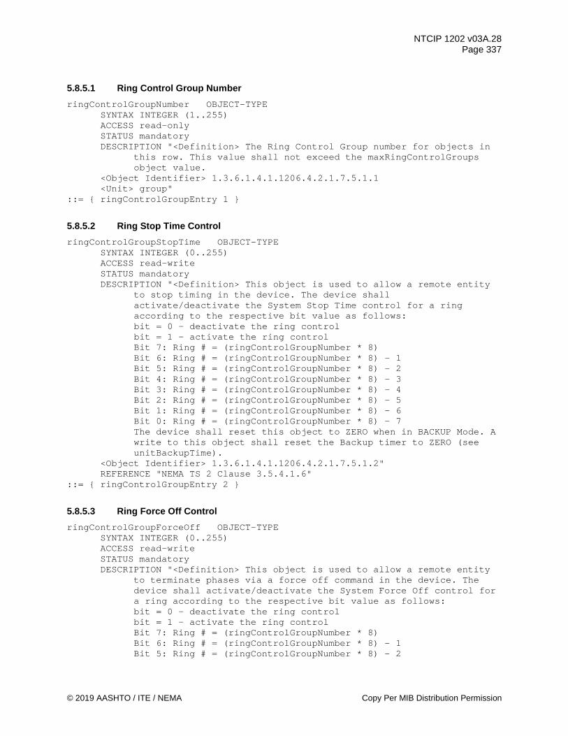
NTCIP 1202 v03A.28 Page 337
© 2019 AASHTO / ITE / NEMA Copy Per MIB Distribution Permission
5.8.5.1 Ring Control Group Number ringControlGroupNumber OBJECT-TYPE
SYNTAX INTEGER (1..255) ACCESS read-only STATUS mandatory DESCRIPTION "<Definition> The Ring Control Group number for objects in
this row. This value shall not exceed the maxRingControlGroups object value.
<Object Identifier> 1.3.6.1.4.1.1206.4.2.1.7.5.1.1 <Unit> group"
::= { ringControlGroupEntry 1 }
5.8.5.2 Ring Stop Time Control ringControlGroupStopTime OBJECT-TYPE
SYNTAX INTEGER (0..255) ACCESS read-write STATUS mandatory DESCRIPTION "<Definition> This object is used to allow a remote entity
to stop timing in the device. The device shall activate/deactivate the System Stop Time control for a ring according to the respective bit value as follows: bit = 0 - deactivate the ring control bit = 1 - activate the ring control Bit 7: Ring # = (ringControlGroupNumber * 8) Bit 6: Ring # = (ringControlGroupNumber * 8) - 1 Bit 5: Ring # = (ringControlGroupNumber * 8) - 2 Bit 4: Ring # = (ringControlGroupNumber * 8) - 3 Bit 3: Ring # = (ringControlGroupNumber * 8) - 4 Bit 2: Ring # = (ringControlGroupNumber * 8) - 5 Bit 1: Ring # = (ringControlGroupNumber * 8) - 6 Bit 0: Ring # = (ringControlGroupNumber * 8) - 7 The device shall reset this object to ZERO when in BACKUP Mode. A write to this object shall reset the Backup timer to ZERO (see unitBackupTime).
<Object Identifier> 1.3.6.1.4.1.1206.4.2.1.7.5.1.2" REFERENCE "NEMA TS 2 Clause 3.5.4.1.6"
::= { ringControlGroupEntry 2 }
5.8.5.3 Ring Force Off Control ringControlGroupForceOff OBJECT-TYPE
SYNTAX INTEGER (0..255) ACCESS read-write STATUS mandatory DESCRIPTION "<Definition> This object is used to allow a remote entity
to terminate phases via a force off command in the device. The device shall activate/deactivate the System Force Off control for a ring according to the respective bit value as follows: bit = 0 - deactivate the ring control bit = 1 - activate the ring control Bit 7: Ring # = (ringControlGroupNumber * 8) Bit 6: Ring # = (ringControlGroupNumber * 8) - 1 Bit 5: Ring # = (ringControlGroupNumber * 8) - 2

NTCIP 1202 v03A.28 Page 338
Copy Per MIB Distribution Permission © 2019 AASHTO / ITE / NEMA
Bit 4: Ring # = (ringControlGroupNumber * 8) - 3 Bit 3: Ring # = (ringControlGroupNumber * 8) - 4 Bit 2: Ring # = (ringControlGroupNumber * 8) - 5 Bit 1: Ring # = (ringControlGroupNumber * 8) - 6 Bit 0: Ring # = (ringControlGroupNumber * 8) - 7 The device shall reset this object to ZERO when in BACKUP Mode. A write to this object shall reset the Backup timer to ZERO (see unitBackupTime).
<Object Identifier> 1.3.6.1.4.1.1206.4.2.1.7.5.1.3" REFERENCE "NEMA TS 2 Clause 3.5.4.1.1"
::= { ringControlGroupEntry 3 }
5.8.5.4 Ring Max 2 Control ringControlGroupMax2 OBJECT-TYPE
SYNTAX INTEGER (0..255) ACCESS read-write STATUS mandatory DESCRIPTION "<Definition> This object is used to allow a remote entity
to request Maximum 2 timings in the device. The device shall activate/deactivate the System Maximum 2 control for a ring according to the respective bit value as follows: bit = 0 - deactivate the ring control bit = 1 - activate the ring control Bit 7: Ring # = (ringControlGroupNumber * 8) Bit 6: Ring # = (ringControlGroupNumber * 8) - 1 Bit 5: Ring # = (ringControlGroupNumber * 8) - 2 Bit 4: Ring # = (ringControlGroupNumber * 8) - 3 Bit 3: Ring # = (ringControlGroupNumber * 8) - 4 Bit 2: Ring # = (ringControlGroupNumber * 8) - 5 Bit 1: Ring # = (ringControlGroupNumber * 8) - 6 Bit 0: Ring # = (ringControlGroupNumber * 8) - 7 The device shall reset this object to ZERO when in BACKUP Mode. A write to this object shall reset the Backup timer to ZERO (see unitBackupTime).
<<Object Identifier> 1.3.6.1.4.1.1206.4.2.1.7.5.1.4" REFERENCE "NEMA TS 2 Clause 3.5.4.1.7"
::= { ringControlGroupEntry 4 }
5.8.5.5 Ring Max Inhibit Control ringControlGroupMaxInhibit OBJECT-TYPE
SYNTAX INTEGER (0..255) ACCESS read-write STATUS mandatory DESCRIPTION "<Definition> This object is used to allow a remote entity to
request internal maximum timings be inhibited in the device. The device shall activate/deactivate the System Max Inhibit control for a ring according to the respective bit value as follows: bit = 0 - deactivate the ring control bit = 1 - activate the ring control Bit 7: Ring # = (ringControlGroupNumber * 8) Bit 6: Ring # = (ringControlGroupNumber * 8) - 1 Bit 5: Ring # = (ringControlGroupNumber * 8) - 2 Bit 4: Ring # = (ringControlGroupNumber * 8) - 3 Bit 3: Ring # = (ringControlGroupNumber * 8) - 4

NTCIP 1202 v03A.28 Page 339
© 2019 AASHTO / ITE / NEMA Copy Per MIB Distribution Permission
Bit 2: Ring # = (ringControlGroupNumber * 8) - 5 Bit 1: Ring # = (ringControlGroupNumber * 8) - 6 Bit 0: Ring # = (ringControlGroupNumber * 8) - 7 The device shall reset this object to ZERO when in BACKUP Mode. A write to this object shall reset the Backup timer to ZERO (see unitBackupTime).
<<Object Identifier> 1.3.6.1.4.1.1206.4.2.1.7.5.1.5" REFERENCE "NEMA TS 2 Clause 3.5.4.1.3"
::= { ringControlGroupEntry 5 }
5.8.5.6 Ring Ped Recycle Control ringControlGroupPedRecycle OBJECT-TYPE
SYNTAX INTEGER (0..255) ACCESS read-write STATUS mandatory DESCRIPTION "<Definition> This object is used to allow a remote entity
to request a pedestrian recycle in the device. The device shall activate/deactivate the System Ped Recycle control for a ring according to the respective bit value as follows: bit = 0 - deactivate the ring control bit = 1 - activate the ring control Bit 7: Ring # = (ringControlGroupNumber * 8) Bit 6: Ring # = (ringControlGroupNumber * 8) - 1 Bit 5: Ring # = (ringControlGroupNumber * 8) - 2 Bit 4: Ring # = (ringControlGroupNumber * 8) - 3 Bit 3: Ring # = (ringControlGroupNumber * 8) - 4 Bit 2: Ring # = (ringControlGroupNumber * 8) - 5 Bit 1: Ring # = (ringControlGroupNumber * 8) - 6 Bit 0: Ring # = (ringControlGroupNumber * 8) - 7 The device shall reset this object to ZERO when in BACKUP Mode. A write to this object shall reset the Backup timer to ZERO (see unitBackupTime).
<Object Identifier> 1.3.6.1.4.1.1206.4.2.1.7.5.1.6" REFERENCE "NEMA TS 2 Clause 3.5.4.1.5"
::= { ringControlGroupEntry 6 }
5.8.5.7 Ring Red Rest Control ringControlGroupRedRest OBJECT-TYPE
SYNTAX INTEGER (0..255) ACCESS read-write STATUS mandatory DESCRIPTION "<Definition> This object is used to allow a remote entity
to request red rest in the device. The device shall activate/deactivate the System Red Rest control for a ring according to the respective bit value as follows: bit = 0 - deactivate the ring control bit = 1 - activate the ring control Bit 7: Ring # = (ringControlGroupNumber * 8) Bit 6: Ring # = (ringControlGroupNumber * 8) - 1 Bit 5: Ring # = (ringControlGroupNumber * 8) - 2 Bit 4: Ring # = (ringControlGroupNumber * 8) - 3 Bit 3: Ring # = (ringControlGroupNumber * 8) - 4 Bit 2: Ring # = (ringControlGroupNumber * 8) - 5 Bit 1: Ring # = (ringControlGroupNumber * 8) - 6 Bit 0: Ring # = (ringControlGroupNumber * 8) - 7

NTCIP 1202 v03A.28 Page 340
Copy Per MIB Distribution Permission © 2019 AASHTO / ITE / NEMA
The device shall reset this object to ZERO when in BACKUP Mode. A write to this object shall reset the Backup timer to ZERO (see unitBackupTime).
<Object Identifier> 1.3.6.1.4.1.1206.4.2.1.7.5.1.7" REFERENCE "NEMA TS 2 Clause 3.5.4.1.2"
::= { ringControlGroupEntry 7 }
5.8.5.8 Ring Omit Red Control ringControlGroupOmitRedClear OBJECT-TYPE
SYNTAX INTEGER (0..255) ACCESS read-write STATUS mandatory DESCRIPTION "<Definition> This object is used to allow a remote entity
to omit red clearances in the device. The device shall activate/deactivate the System Omit Red Clear control for a ring according to the respective bit value as follows: bit = 0 - deactivate the ring control bit = 1 - activate the ring control Bit 7: Ring # = (ringControlGroupNumber * 8) Bit 6: Ring # = (ringControlGroupNumber * 8) - 1 Bit 5: Ring # = (ringControlGroupNumber * 8) - 2 Bit 4: Ring # = (ringControlGroupNumber * 8) - 3 Bit 3: Ring # = (ringControlGroupNumber * 8) - 4 Bit 2: Ring # = (ringControlGroupNumber * 8) - 5 Bit 1: Ring # = (ringControlGroupNumber * 8) - 6 Bit 0: Ring # = (ringControlGroupNumber * 8) - 7 The device shall reset this object to ZERO when in BACKUP Mode. A write to this object shall reset the Backup timer to ZERO (see unitBackupTime).
<Object Identifier> 1.3.6.1.4.1.1206.4.2.1.7.5.1.8" REFERENCE "NEMA TS 2 Clause 3.5.4.1.4"
::= { ringControlGroupEntry 8 }
5.8.5.9 Ring Max 3 Control ringControlGroupMax3 OBJECT-TYPE
SYNTAX INTEGER (0..255) ACCESS read-write STATUS mandatory DESCRIPTION "<Definition> This object is used to allow a remote entity
to request Maximum 3 timings in the device. The device shall activate/deactivate the System Maximum 3 control for a ring according to the respective bit value as follows: bit = 0 - deactivate the ring control bit = 1 - activate the ring control Bit 7: Ring # = (ringControlGroupNumber * 8) Bit 6: Ring # = (ringControlGroupNumber * 8) - 1 Bit 5: Ring # = (ringControlGroupNumber * 8) - 2 Bit 4: Ring # = (ringControlGroupNumber * 8) - 3 Bit 3: Ring # = (ringControlGroupNumber * 8) - 4 Bit 2: Ring # = (ringControlGroupNumber * 8) - 5 Bit 1: Ring # = (ringControlGroupNumber * 8) - 6 Bit 0: Ring # = (ringControlGroupNumber * 8) - 7 The device shall reset this object to ZERO when in BACKUP Mode. A write to this object shall reset the Backup timer to ZERO (see unitBackupTime).

NTCIP 1202 v03A.28 Page 341
© 2019 AASHTO / ITE / NEMA Copy Per MIB Distribution Permission
<Object Identifier> 1.3.6.1.4.1.1206.4.2.1.7.5.1.9" ::= { ringControlGroupEntry 9 }
5.8.6 Ring Status Table ringStatusTable OBJECT-TYPE
SYNTAX SEQUENCE OF RingStatusEntry ACCESS not-accessible STATUS mandatory DESCRIPTION "<Definition> A table containing Actuated Controller Unit
Ring Status. The number of rows in this table is equal to the maxRings object.
<TableType> static <Object Identifier> 1.3.6.1.4.1.1206.4.2.1.7.6"
::= { ring 6 } ringStatusEntry OBJECT-TYPE
SYNTAX RingStatusEntry ACCESS not-accessible STATUS mandatory DESCRIPTION "<Definition> Ring Status for an Actuated Controller Unit
ring. <Object Identifier> 1.3.6.1.4.1.1206.4.2.1.7.6.1" INDEX { sequenceRingNumber }
::= { ringStatusTable 1 } RingStatusEntry ::= SEQUENCE {
ringStatus INTEGER }
5.8.6.1 Ring Status ringStatus OBJECT-TYPE
SYNTAX INTEGER (0..255) ACCESS read-only STATUS mandatory DESCRIPTION "<Definition> The Ring Status for this ring.
Bit 7: Reserved (always zero) Bit 6: Reserved (always zero) Bit 5: Force Off - When bit = 1, the active phase in the ring was
terminated by Force Off Bit 4: Max Out - When bit = 1, the active phase in the ring was
terminated by Max Out Bit 3: Gap Out - When bit = 1, the active phase in the ring was
terminated by Gap Out Bit 2: Coded Status Bit C Bit 1: Coded Status Bit B Bit 0: Coded Status Bit A +======+=====+=====+=====+===============+ | Code | Bit States | State | | ## | A | B | C | Names | +======+=====+=====+=====+===============+ | 0 | 0 | 0 | 0 | Min Green | | 1 | 1 | 0 | 0 | Extension | | 2 | 0 | 1 | 0 | Maximum | | 3 | 1 | 1 | 0 | Green Rest | | 4 | 0 | 0 | 1 | Yellow Change | | 5 | 1 | 0 | 1 | Red Clearance |

NTCIP 1202 v03A.28 Page 342
Copy Per MIB Distribution Permission © 2019 AASHTO / ITE / NEMA
| 6 | 0 | 1 | 1 | Red Rest | | 7 | 1 | 1 | 1 | Undefined | +======+=====+=====+=====+===============+ NEMA TS 2 Clause 3.5.4.2 provides further definition of Coded Status Bits.
<Object Identifier> 1.3.6.1.4.1.1206.4.2.1.7.6.1.1" ::= { ringStatusEntry 1 }
5.9 Channel Parameters channel OBJECT IDENTIFIER ::= { asc 8 } --This defines a node for supporting channel objects.
5.9.1 Maximum Channels maxChannels OBJECT-TYPE
SYNTAX INTEGER (1..255) ACCESS read-only STATUS mandatory DESCRIPTION "<Definition> The Maximum Number of Channels this Actuated
Controller Unit supports. This object indicates the maximum rows which shall appear in the channelTable object.
<Object Identifier> 1.3.6.1.4.1.1206.4.2.1.8.1 <Unit> channel"
::= { channel 1 }
5.9.2 Channel Table channelTable OBJECT-TYPE
SYNTAX SEQUENCE OF ChannelEntry ACCESS not-accessible STATUS mandatory DESCRIPTION "<Definition> A table containing Actuated Controller Unit
channel parameters. The number of rows in this table is equal to the maxChannels object.
<TableType> static <Object Identifier> 1.3.6.1.4.1.1206.4.2.1.8.2"
::= { channel 2 } channelEntry OBJECT-TYPE
SYNTAX ChannelEntry ACCESS not-accessible STATUS mandatory DESCRIPTION "<Definition> Parameters for a specific Actuated Controller
Unit channel. <Object Identifier> 1.3.6.1.4.1.1206.4.2.1.8.2.1" INDEX { channelNumber }
::= { channelTable 1 } ChannelEntry ::= SEQUENCE {
channelNumber INTEGER, channelControlSource INTEGER, channelControlType INTEGER, channelFlash INTEGER,
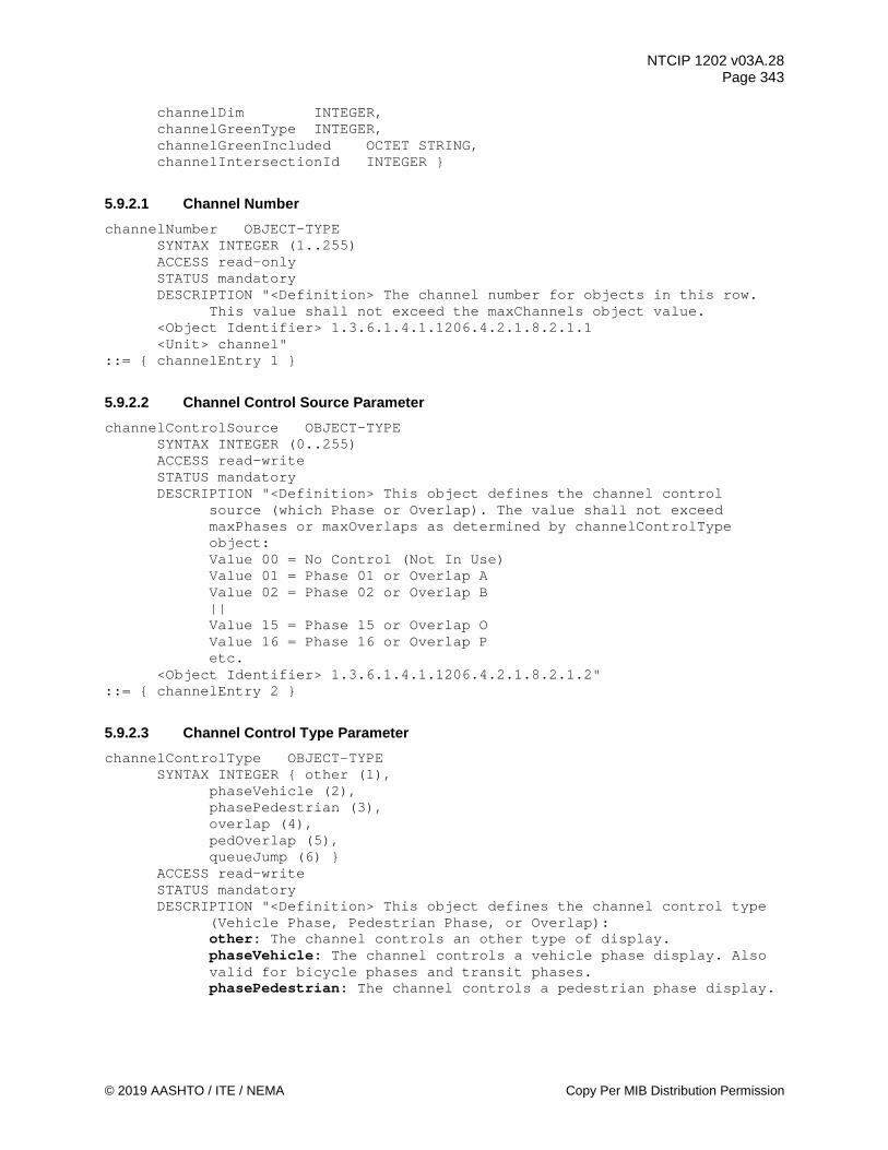
NTCIP 1202 v03A.28 Page 343
© 2019 AASHTO / ITE / NEMA Copy Per MIB Distribution Permission
channelDim INTEGER, channelGreenType INTEGER, channelGreenIncluded OCTET STRING, channelIntersectionId INTEGER }
5.9.2.1 Channel Number channelNumber OBJECT-TYPE
SYNTAX INTEGER (1..255) ACCESS read-only STATUS mandatory DESCRIPTION "<Definition> The channel number for objects in this row.
This value shall not exceed the maxChannels object value. <Object Identifier> 1.3.6.1.4.1.1206.4.2.1.8.2.1.1 <Unit> channel"
::= { channelEntry 1 }
5.9.2.2 Channel Control Source Parameter channelControlSource OBJECT-TYPE
SYNTAX INTEGER (0..255) ACCESS read-write STATUS mandatory DESCRIPTION "<Definition> This object defines the channel control
source (which Phase or Overlap). The value shall not exceed maxPhases or maxOverlaps as determined by channelControlType object: Value 00 = No Control (Not In Use) Value 01 = Phase 01 or Overlap A Value 02 = Phase 02 or Overlap B || Value 15 = Phase 15 or Overlap O Value 16 = Phase 16 or Overlap P etc.
<Object Identifier> 1.3.6.1.4.1.1206.4.2.1.8.2.1.2" ::= { channelEntry 2 }
5.9.2.3 Channel Control Type Parameter channelControlType OBJECT-TYPE
SYNTAX INTEGER { other (1), phaseVehicle (2), phasePedestrian (3), overlap (4), pedOverlap (5), queueJump (6) }
ACCESS read-write STATUS mandatory DESCRIPTION "<Definition> This object defines the channel control type
(Vehicle Phase, Pedestrian Phase, or Overlap): other: The channel controls an other type of display. phaseVehicle: The channel controls a vehicle phase display. Also valid for bicycle phases and transit phases. phasePedestrian: The channel controls a pedestrian phase display.

NTCIP 1202 v03A.28 Page 344
Copy Per MIB Distribution Permission © 2019 AASHTO / ITE / NEMA
overlap: The channel controls an overlap display, which might include flashing yellow arrows, flashing red arrows, vehicle overlaps, bicycle overlaps and transit overlaps. pedOverlap: The channel controls an overlap for pedestrian display. queueJump: The channel controls a queue jump display typically used for transit priority
<Object Identifier> 1.3.6.1.4.1.1206.4.2.1.8.2.1.3" ::= { channelEntry 3 }
5.9.2.4 Channel Flash Parameter channelFlash OBJECT-TYPE
SYNTAX INTEGER (0..255) ACCESS read-write STATUS mandatory DESCRIPTION "<Definition> This object defines the channel state during
Automatic Flash. Bit 7: Reserved Bit 6: Reserved Bit 5: Reserved Bit 4: Reserved Bit 3: Flash Alternate Half Hertz
Bit=0: Off/Disabled & Bit=1: On/Enabled Bit 2: Flash Red
Bit=0: Off/Red Dark & Bit=1: On/Flash Red Bit 1: Flash Yellow
Bit=0: Off/Yellow Dark & Bit=1: On/Flash Yellow Bit 0: Reserved A SET of both bits 1 & 2 shall result in bit 1=0 and bit 2=1. A SET of a 'reserved' bit to a value other than zero (0) shall return a badValue(3) error.
<Object Identifier> 1.3.6.1.4.1.1206.4.2.1.8.2.1.4" ::= { channelEntry 4 }
5.9.2.5 Channel Dim Parameter channelDim OBJECT-TYPE
SYNTAX INTEGER (0..255) ACCESS read-write STATUS mandatory DESCRIPTION "<Definition> This object defines the channel state during
Dimming. Dimming shall be accomplished by the elimination of alternate one-half segments from the AC sinusoid applied to the field terminals. Bit 7: Reserved Bit 6: Reserved Bit 5: Reserved Bit 4: Reserved Bit 3: Dim Alternate Half Line Cycle
Bit=0: Off/+ half cycle & Bit=1: On/- half cycle Bit 2: Dim Red
Bit=0: Off/Red Not Dimmed & Bit=1: On/Dimmed Red Bit 1: Dim Yellow
Bit=0: Off / Yellow Not Dimmed & Bit=1: On / Dimmed Yellow Bit 0: Dim Green
Bit=0: Off / Green Not Dimmed & Bit=1: On / Dimmed Green
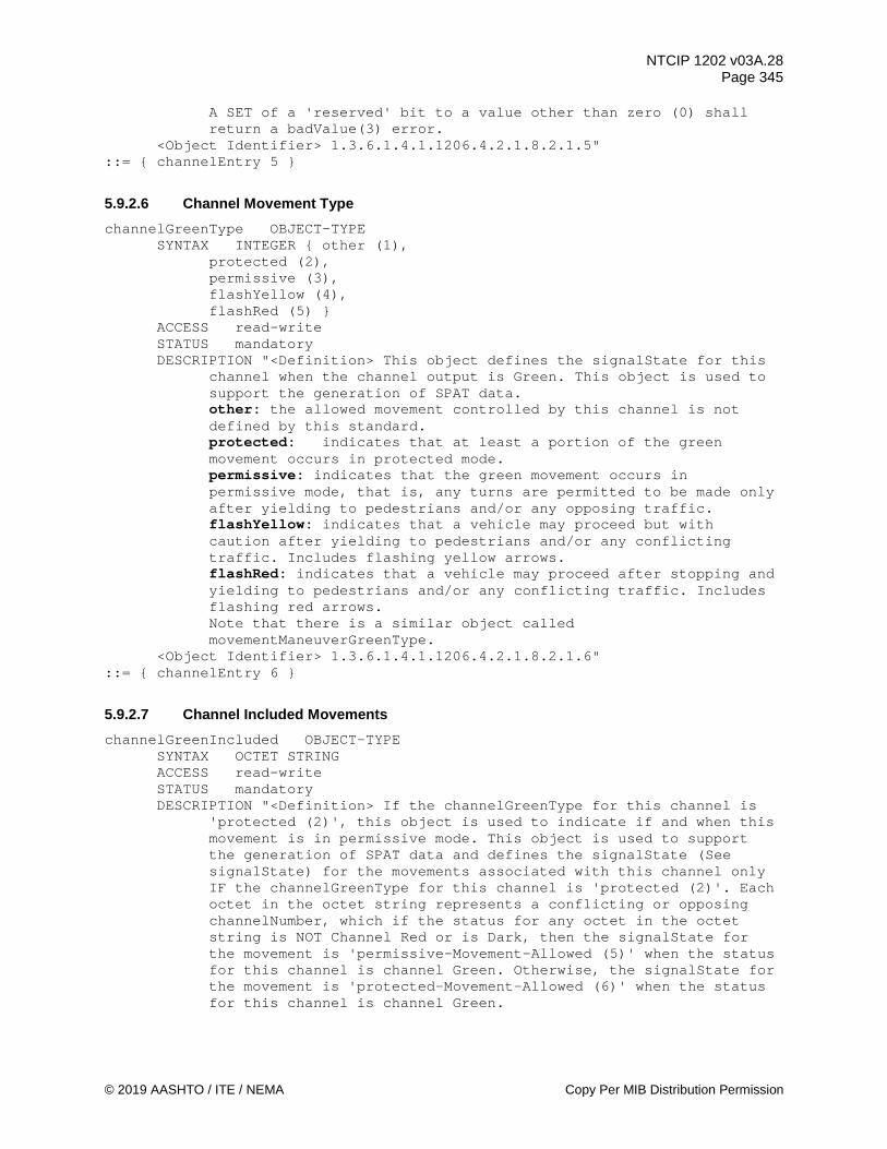
NTCIP 1202 v03A.28 Page 345
© 2019 AASHTO / ITE / NEMA Copy Per MIB Distribution Permission
A SET of a 'reserved' bit to a value other than zero (0) shall return a badValue(3) error.
<Object Identifier> 1.3.6.1.4.1.1206.4.2.1.8.2.1.5" ::= { channelEntry 5 }
5.9.2.6 Channel Movement Type channelGreenType OBJECT-TYPE
SYNTAX INTEGER { other (1), protected (2), permissive (3), flashYellow (4), flashRed (5) } ACCESS read-write STATUS mandatory DESCRIPTION "<Definition> This object defines the signalState for this
channel when the channel output is Green. This object is used to support the generation of SPAT data. other: the allowed movement controlled by this channel is not defined by this standard. protected: indicates that at least a portion of the green movement occurs in protected mode. permissive: indicates that the green movement occurs in permissive mode, that is, any turns are permitted to be made only after yielding to pedestrians and/or any opposing traffic. flashYellow: indicates that a vehicle may proceed but with caution after yielding to pedestrians and/or any conflicting traffic. Includes flashing yellow arrows. flashRed: indicates that a vehicle may proceed after stopping and yielding to pedestrians and/or any conflicting traffic. Includes flashing red arrows. Note that there is a similar object called movementManeuverGreenType.
<Object Identifier> 1.3.6.1.4.1.1206.4.2.1.8.2.1.6" ::= { channelEntry 6 }
5.9.2.7 Channel Included Movements channelGreenIncluded OBJECT-TYPE
SYNTAX OCTET STRING ACCESS read-write STATUS mandatory DESCRIPTION "<Definition> If the channelGreenType for this channel is
'protected (2)', this object is used to indicate if and when this movement is in permissive mode. This object is used to support the generation of SPAT data and defines the signalState (See signalState) for the movements associated with this channel only IF the channelGreenType for this channel is 'protected (2)'. Each octet in the octet string represents a conflicting or opposing channelNumber, which if the status for any octet in the octet string is NOT Channel Red or is Dark, then the signalState for the movement is 'permissive-Movement-Allowed (5)' when the status for this channel is channel Green. Otherwise, the signalState for the movement is 'protected-Movement-Allowed (6)' when the status for this channel is channel Green.

NTCIP 1202 v03A.28 Page 346
Copy Per MIB Distribution Permission © 2019 AASHTO / ITE / NEMA
If channelGreenType in this row is not 'protected (2)', then this object value is ignored. It is assumed that a clearance state following a signalState of 'permissive movement allowed' will be a signalState of 'permissive clearance', and a clearance state following a signalState of 'protected movement allowed' will be a signalState of 'protected movement allowed'. For example, assume channelNumber 1 represents a northbound left turn, while channelNumber 2 is a southbound through movement. A channelGreenType.1 of 'protected (2)' and channelGreenIncluded.1 of '02' indicates that if the status of channelNumber 2 is NOT Channel Red or is dark, then signalState for the movement associated with channelNumber.1 is 'permissive-Movement-Allowed (5)' when the status for channelNumber.1 is channel Green. Otherwise, the signalState for the movement associated with channelNumber.1 is 'protected-Movement-Allowed (6)' when the status for this channel is channel Green.
<Object Identifier> 1.3.6.1.4.1.1206.4.2.1.8.2.1.7" ::= { channelEntry 7 }
5.9.2.8 Channel Intersection Identifier channelIntersectionId OBJECT-TYPE
SYNTAX INTEGER (0..65535) ACCESS read-write STATUS mandatory DESCRIPTION "<Definition> To support SAE J2735, this object is used to
support the exchange of SPAT data and contains the (regionally) unique identifier of the intersection that the channel output is associated with. It is expected that this same identifier will be broadcasted in a MAP data message that describes the roadway geometry configuration of this intersection.
<Object Identifier> 1.3.6.1.4.1.1206.4.2.1.8.2.1.8" REFERENCE "SAE J2735_201603 DE_IntersectionID"
::= { channelEntry 8 }
5.9.3 Maximum Channel Status Groups maxChannelStatusGroups OBJECT-TYPE
SYNTAX INTEGER (1..255) ACCESS read-only STATUS mandatory DESCRIPTION "<Definition> The maximum number of Channel Status Groups
(8 channels per group) this Actuated Controller Unit supports. This value is equal to TRUNCATE [(maxChannels + 7) / 8]. This object indicates the maximum rows which shall appear in the channelStatusGroupTable object.
<Object Identifier> 1.3.6.1.4.1.1206.4.2.1.8.3 <Unit> group"
::= { channel 3 }
5.9.4 Channel Status Group Table channelStatusGroupTable OBJECT-TYPE

NTCIP 1202 v03A.28 Page 347
© 2019 AASHTO / ITE / NEMA Copy Per MIB Distribution Permission
SYNTAX SEQUENCE OF ChannelStatusGroupEntry ACCESS not-accessible STATUS mandatory DESCRIPTION "<Definition> A table containing Actuated Controller Unit
channel output (Red, Yellow, & Green) status in groups of eight channels. The number of rows in this table is equal to the maxChannelStatusGroups object.
<TableType> static <Object Identifier> 1.3.6.1.4.1.1206.4.2.1.8.4"
::= { channel 4 } channelStatusGroupEntry OBJECT-TYPE
SYNTAX ChannelStatusGroupEntry ACCESS not-accessible STATUS mandatory DESCRIPTION "<Definition> Red, Yellow, & Green Output Status for eight
Actuated Controller Unit channels. <Object Identifier> 1.3.6.1.4.1.1206.4.2.1.8.4.1" INDEX { channelStatusGroupNumber }
::= { channelStatusGroupTable 1 } ChannelStatusGroupEntry ::= SEQUENCE {
channelStatusGroupNumber INTEGER, channelStatusGroupReds INTEGER, channelStatusGroupYellows INTEGER, channelStatusGroupGreens INTEGER }
5.9.4.1 Channel Status Group Number channelStatusGroupNumber OBJECT-TYPE
SYNTAX INTEGER (1..255) ACCESS read-only STATUS mandatory DESCRIPTION "<Definition> The channelStatusGroup number for objects in
this row. This value shall not exceed the maxChannelStatusGroups object value.
<Object Identifier> 1.3.6.1.4.1.1206.4.2.1.8.4.1.1 <Unit> group"
::= { channelStatusGroupEntry 1 }
5.9.4.2 Channel Status Group Reds channelStatusGroupReds OBJECT-TYPE
SYNTAX INTEGER (0..255) ACCESS read-only STATUS mandatory DESCRIPTION "<Definition> Channel Red Output Status Mask, when a bit=1,
the Channel Red is currently active. When a bit=0, the Channel Red is NOT currently active. Bit 7: Channel # = (channelStatusGroupNumber * 8) Bit 6: Channel # = (channelStatusGroupNumber * 8) - 1 Bit 5: Channel # = (channelStatusGroupNumber * 8) - 2 Bit 4: Channel # = (channelStatusGroupNumber * 8) - 3 Bit 3: Channel # = (channelStatusGroupNumber * 8) - 4 Bit 2: Channel # = (channelStatusGroupNumber * 8) - 5 Bit 1: Channel # = (channelStatusGroupNumber * 8) - 6 Bit 0: Channel # = (channelStatusGroupNumber * 8) - 7

NTCIP 1202 v03A.28 Page 348
Copy Per MIB Distribution Permission © 2019 AASHTO / ITE / NEMA
<Object Identifier> 1.3.6.1.4.1.1206.4.2.1.8.4.1.2" ::= { channelStatusGroupEntry 2 }
5.9.4.3 Channel Status Group Yellows channelStatusGroupYellows OBJECT-TYPE
SYNTAX INTEGER (0..255) ACCESS read-only STATUS mandatory DESCRIPTION "<Definition> Channel Yellow Output Status Mask, when a
bit=1, the Channel Yellow is currently active. When a bit=0, the Channel Yellow is NOT currently active. Bit 7: Channel # = (channelStatusGroupNumber * 8) Bit 6: Channel # = (channelStatusGroupNumber * 8) - 1 Bit 5: Channel # = (channelStatusGroupNumber * 8) - 2 Bit 4: Channel # = (channelStatusGroupNumber * 8) - 3 Bit 3: Channel # = (channelStatusGroupNumber * 8) - 4 Bit 2: Channel # = (channelStatusGroupNumber * 8) - 5 Bit 1: Channel # = (channelStatusGroupNumber * 8) - 6 Bit 0: Channel # = (channelStatusGroupNumber * 8) - 7
<Object Identifier> 1.3.6.1.4.1.1206.4.2.1.8.4.1.3" ::= { channelStatusGroupEntry 3 }
5.9.4.4 Channel Status Group Greens channelStatusGroupGreens OBJECT-TYPE
SYNTAX INTEGER (0..255) ACCESS read-only STATUS mandatory DESCRIPTION "<Definition> Channel Green Output Status Mask, when a
bit=1, the Channel Green is currently active. When a bit=0, the Channel Green is NOT currently active. Bit 7: Channel # = (channelStatusGroupNumber * 8) Bit 6: Channel # = (channelStatusGroupNumber * 8) - 1 Bit 5: Channel # = (channelStatusGroupNumber * 8) - 2 Bit 4: Channel # = (channelStatusGroupNumber * 8) - 3 Bit 3: Channel # = (channelStatusGroupNumber * 8) - 4 Bit 2: Channel # = (channelStatusGroupNumber * 8) - 5 Bit 1: Channel # = (channelStatusGroupNumber * 8) - 6 Bit 0: Channel # = (channelStatusGroupNumber * 8) - 7
<Object Identifier> 1.3.6.1.4.1.1206.4.2.1.8.4.1.4" ::= { channelStatusGroupEntry 4 }
5.10 Overlap Parameters overlap OBJECT IDENTIFIER ::= { asc 9 } -- This node contains objects that configure, monitor and -- control overlap functions.
5.10.1 Maximum Overlaps maxOverlaps OBJECT-TYPE
SYNTAX INTEGER (1..255) ACCESS read-only

NTCIP 1202 v03A.28 Page 349
© 2019 AASHTO / ITE / NEMA Copy Per MIB Distribution Permission
STATUS mandatory DESCRIPTION "<Definition> The Maximum Number of Overlaps this Actuated
Controller Unit supports. This object indicates the maximum number of rows which shall appear in the overlapTable object.
<Object Identifier> 1.3.6.1.4.1.1206.4.2.1.9.1 <Unit> overlap"
::= { overlap 1 }
5.10.2 Overlap Table overlapTable OBJECT-TYPE
SYNTAX SEQUENCE OF OverlapEntry ACCESS not-accessible STATUS mandatory DESCRIPTION "<Definition> A table containing Actuated Controller Unit
overlap parameters. The number of rows in this table is equal to the maxOverlaps object.
<TableType> static <Object Identifier> 1.3.6.1.4.1.1206.4.2.1.9.2"
::= { overlap 2 } overlapEntry OBJECT-TYPE
SYNTAX OverlapEntry ACCESS not-accessible STATUS mandatory DESCRIPTION "<Definition> Parameters for a specific Actuated Controller
Unit overlap. <Object Identifier> 1.3.6.1.4.1.1206.4.2.1.9.2.1" INDEX { overlapNumber }
::= { overlapTable 1 } OverlapEntry ::= SEQUENCE {
overlapNumber INTEGER, overlapType INTEGER, overlapIncludedPhases OCTET STRING, overlapModifierPhases OCTET STRING, overlapTrailGreen INTEGER, overlapTrailYellow INTEGER, overlapTrailRed INTEGER, overlapWalk INTEGER, overlapPedClearance INTEGER, overlapConflictingPedPhases OCTET STRING }
5.10.2.1 Overlap Number overlapNumber OBJECT-TYPE
SYNTAX INTEGER (1..255) ACCESS read-only STATUS mandatory DESCRIPTION "<Definition> The overlap number for objects in this row.
The value shall not exceed the maxOverlaps object. The value maps to the Overlap as follows: 1 = Overlap A, 2 = Overlap B etc.
<Object Identifier> 1.3.6.1.4.1.1206.4.2.1.9.2.1.1 <Unit> overlap"
::= { overlapEntry 1 }
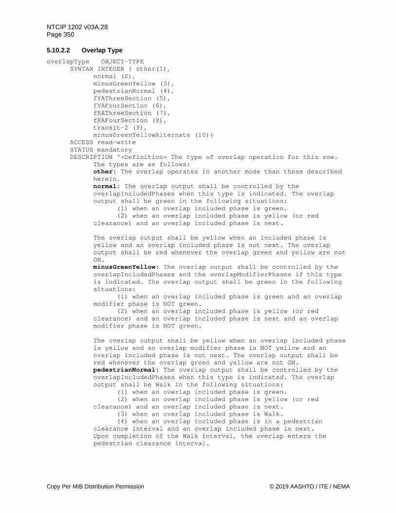
NTCIP 1202 v03A.28 Page 350
Copy Per MIB Distribution Permission © 2019 AASHTO / ITE / NEMA
5.10.2.2 Overlap Type overlapType OBJECT-TYPE
SYNTAX INTEGER { other(1), normal (2), minusGreenYellow (3), pedestrianNormal (4), fYAThreeSection (5), fYAFourSection (6), fRAThreeSection (7), fRAFourSection (8), transit-2 (9), minusGreenYellowAlternate (10)}
ACCESS read-write STATUS mandatory DESCRIPTION "<Definition> The type of overlap operation for this row.
The types are as follows: other: The overlap operates in another mode than those described herein. normal: The overlap output shall be controlled by the overlapIncludedPhases when this type is indicated. The overlap output shall be green in the following situations:
(1) when an overlap included phase is green. (2) when an overlap included phase is yellow (or red
clearance) and an overlap included phase is next.
The overlap output shall be yellow when an included phase is yellow and an overlap included phase is not next. The overlap output shall be red whenever the overlap green and yellow are not ON. minusGreenYellow: The overlap output shall be controlled by the overlapIncludedPhases and the overlapModifierPhases if this type is indicated. The overlap output shall be green in the following situations:
(1) when an overlap included phase is green and an overlap modifier phase is NOT green.
(2) when an overlap included phase is yellow (or red clearance) and an overlap included phase is next and an overlap modifier phase is NOT green.
The overlap output shall be yellow when an overlap included phase is yellow and an overlap modifier phase is NOT yellow and an overlap included phase is not next. The overlap output shall be red whenever the overlap green and yellow are not ON. pedestrianNormal: The overlap output shall be controlled by the overlapIncludedPhases when this type is indicated. The overlap output shall be Walk in the following situations:
(1) when an overlap included phase is green. (2) when an overlap included phase is yellow (or red
clearance) and an overlap included phase is next. (3) when an overlap included phase is Walk. (4) when an overlap included phase is in a pedestrian
clearance interval and an overlap included phase is next. Upon completion of the Walk interval, the overlap enters the
pedestrian clearance interval.

NTCIP 1202 v03A.28 Page 351
© 2019 AASHTO / ITE / NEMA Copy Per MIB Distribution Permission
The overlap output shall exit the pedestrian clearance interval to steady Dont Walk when the programmed pedestrian clearance time expires. The overlap output shall be steady Dont Walk whenever the overlap Walk and pedestrian clearance are not ON. fYAThreeSection: The overlap output shall be controlled by the overlapIncludedPhases and the overlapModifierPhases if this type is indicated. It shall be used with a 3-section signal head where the overlap output drives the green arrow, combined yellow/flashing yellow arrow, and red arrow. The permissive through phase opposing the left-turn signal is the overlapIncludedPhases and the associated left-turn protected phase is the overlapModifierPhases. The overlap output shall be FYA in the following situations:
(1) when an overlap included phase is green and an overlap modifier phase is NOT green.
(2) when an overlap included phase is yellow (or red clearance), an overlap included phase is next or an overlap modifier phase is next, and a modifier phase is NOT green.
The overlap output shall be yellow: (1) when an overlap included phase is yellow, an overlap included phase is not next, and an overlap modifier phase is NOT green. (2) when an overlap modifier phase is yellow. The overlap output shall be red: (1) when an overlap included phase is red, an overlap modifier phase is NOT green, and an overlap modifier phase is NOT yellow. (2) when an overlap modifier phase is timing a red-clearance interval. The overlap output shall be green: (1) when an overlap modifier phase is green. fYAFourSection: The overlap output shall be controlled by the overlapIncludedPhases and the overlapModifierPhases if this type is indicated. It shall be used with a 4-section signal head where the overlap output drives the flashing yellow arrow, yellow and red. The permissive through phase opposing the left-turn signal is the overlapIncludedPhases and the associated left-turn protected phase is the overlapModifierPhases. The overlap output shall be FYA in the following situations:
(1) when an overlap included phase is green and an overlap modifier phase is NOT green.
(2) when an overlap included phase is yellow (or red clearance), an overlap included phase or an overlap modifier phase is next and an overlap modifier phase is NOT green. The overlap output shall be yellow: (1) when an overlap included phase is yellow, an overlap included phase is not next, and an overlap modifier phase is NOT green. (2) when an overlap modifier phase is yellow. The overlap output shall be red:
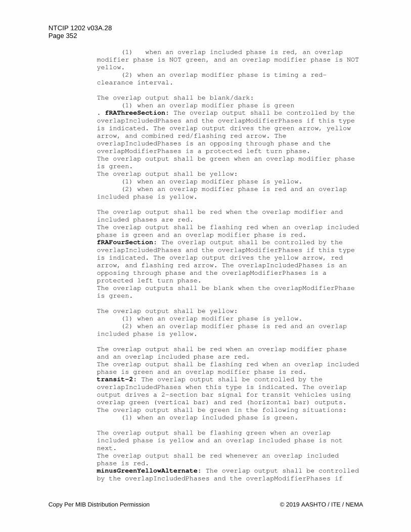
NTCIP 1202 v03A.28 Page 352
Copy Per MIB Distribution Permission © 2019 AASHTO / ITE / NEMA
(1) when an overlap included phase is red, an overlap modifier phase is NOT green, and an overlap modifier phase is NOT yellow. (2) when an overlap modifier phase is timing a red-clearance interval. The overlap output shall be blank/dark: (1) when an overlap modifier phase is green . fRAThreeSection: The overlap output shall be controlled by the overlapIncludedPhases and the overlapModifierPhases if this type is indicated. The overlap output drives the green arrow, yellow arrow, and combined red/flashing red arrow. The overlapIncludedPhases is an opposing through phase and the overlapModifierPhases is a protected left turn phase. The overlap output shall be green when an overlap modifier phase is green. The overlap output shall be yellow:
(1) when an overlap modifier phase is yellow. (2) when an overlap modifier phase is red and an overlap
included phase is yellow.
The overlap output shall be red when the overlap modifier and included phases are red. The overlap output shall be flashing red when an overlap included phase is green and an overlap modifier phase is red. fRAFourSection: The overlap output shall be controlled by the overlapIncludedPhases and the overlapModifierPhases if this type is indicated. The overlap output drives the yellow arrow, red arrow, and flashing red arrow. The overlapIncludedPhases is an opposing through phase and the overlapModifierPhases is a protected left turn phase. The overlap outputs shall be blank when the overlapModifierPhase is green. The overlap output shall be yellow:
(1) when an overlap modifier phase is yellow. (2) when an overlap modifier phase is red and an overlap
included phase is yellow.
The overlap output shall be red when an overlap modifier phase and an overlap included phase are red. The overlap output shall be flashing red when an overlap included phase is green and an overlap modifier phase is red. transit-2: The overlap output shall be controlled by the overlapIncludedPhases when this type is indicated. The overlap output drives a 2-section bar signal for transit vehicles using overlap green (vertical bar) and red (horizontal bar) outputs. The overlap output shall be green in the following situations:
(1) when an overlap included phase is green.
The overlap output shall be flashing green when an overlap included phase is yellow and an overlap included phase is not next. The overlap output shall be red whenever an overlap included phase is red. minusGreenYellowAlternate: The overlap output shall be controlled by the overlapIncludedPhases and the overlapModifierPhases if

NTCIP 1202 v03A.28 Page 353
© 2019 AASHTO / ITE / NEMA Copy Per MIB Distribution Permission
this type is indicated. The overlap output shall be green in the following situations:
(1) when an overlap included phase is green and an overlap modifier phase is NOT green.
(2) when an overlap included phase is yellow (or red clearance) and an overlap included phase is next and an overlap modifier phase is NOT green and an overlap modifier phase is not next.
The overlap output shall be yellow when an overlap included phase is yellow and an overlap modifier phase is NOT yellow and an overlap included phase is not next. The overlap output shall be red whenever the overlap green and yellow are not ON. Note: Each enumeration requires the user to understand and avoid violation of MUTCD operational guidelines.
<Object Identifier> 1.3.6.1.4.1.1206.4.2.1.9.2.1.2" ::= { overlapEntry 2 }
5.10.2.3 Overlap Included Phase Parameter overlapIncludedPhases OBJECT-TYPE
SYNTAX OCTET STRING ACCESS read-write STATUS mandatory DESCRIPTION "<Definition> Each octet is a Phase (number) that shall be
an included phase for the overlap. The phase number value shall not exceed the maxPhases object value.
<Object Identifier> 1.3.6.1.4.1.1206.4.2.1.9.2.1.3" ::= { overlapEntry 3 }
5.10.2.4 Overlap Modifier Phase Parameter overlapModifierPhases OBJECT-TYPE
SYNTAX OCTET STRING ACCESS read-write STATUS mandatory DESCRIPTION "<Definition> Each octet is a Phase (number) that shall be
a modifier phase for the overlap. The phase number value shall not exceed the maxPhases object value. The use of this object is defined by the overlapType.
<Object Identifier> 1.3.6.1.4.1.1206.4.2.1.9.2.1.4" ::= { overlapEntry 4 }
5.10.2.5 Overlap Trailing Green Parameter overlapTrailGreen OBJECT-TYPE
SYNTAX INTEGER (0..255) ACCESS read-write STATUS mandatory DESCRIPTION "<Definition> Overlap Trailing Green Parameter in seconds
(0-255 sec). When this value is greater than zero and the overlap green (or walk) would normally terminate, the overlap green (or walk) shall be extended by this additional time. This is applicable to vehicle phases, bicycle phases, and transit phases.
<Object Identifier> 1.3.6.1.4.1.1206.4.2.1.9.2.1.5

NTCIP 1202 v03A.28 Page 354
Copy Per MIB Distribution Permission © 2019 AASHTO / ITE / NEMA
<Unit> second" ::= { overlapEntry 5 }
5.10.2.6 Overlap Trailing Yellow Change Parameter overlapTrailYellow OBJECT-TYPE
SYNTAX INTEGER (0..255) ACCESS read-write STATUS mandatory DESCRIPTION "<Definition> Overlap Trailing Yellow Change Parameter in
tenth seconds (NEMA range: 3.0-25.5 sec). When the overlap green has been extended (Trailing Green), this value shall determine the current length of the Yellow Change interval for the overlap. This is applicable to vehicle phases, bicycle phases, and transit phases.
<Object Identifier> 1.3.6.1.4.1.1206.4.2.1.9.2.1.6 <Unit> tenth second"
::= { overlapEntry 6 }
5.10.2.7 Overlap Trailing Red Clear Parameter overlapTrailRed OBJECT-TYPE
SYNTAX INTEGER (0..255) ACCESS read-write STATUS mandatory DESCRIPTION "<Definition> Overlap Trailing Red Clear Parameter in tenth
seconds (0-25.5 sec). When the overlap green has been extended (Trailing Green), this value shall determine the current length of the Red Clearance interval for the overlap. This is applicable to vehicle phases, bicycle phases, and transit phases.
<Object Identifier> 1.3.6.1.4.1.1206.4.2.1.9.2.1.7 <Unit> tenth second"
::= { overlapEntry 7 }
5.10.2.8 Overlap Walk Parameter overlapWalk OBJECT-TYPE
SYNTAX INTEGER (0..255) ACCESS read-write STATUS mandatory DESCRIPTION "<Definition> Overlap Walk Parameter in seconds (0-255
sec). This value is the length of the walk interval for a pedestrian overlap. Upon completion of the Walk interval, the overlap enters the pedestrian clearance interval.
<Object Identifier> 1.3.6.1.4.1.1206.4.2.1.9.2.1.8 <Unit> second"
::= { overlapEntry 8 }
5.10.2.9 Overlap Pedestrian Clearance Parameter overlapPedClearance OBJECT-TYPE
SYNTAX INTEGER (0..255) ACCESS read-write STATUS mandatory

NTCIP 1202 v03A.28 Page 355
© 2019 AASHTO / ITE / NEMA Copy Per MIB Distribution Permission
DESCRIPTION "<Definition> Overlap Pedestrian Clearance Parameter in seconds (0-255 sec). This value is the length of the pedestrian clearance interval.
<Object Identifier> 1.3.6.1.4.1.1206.4.2.1.9.2.1.9 <Unit> second"
::= { overlapEntry 9 }
5.10.2.10 Overlap Conflicting Pedestrian Phase Parameter overlapConflictingPedPhases OBJECT-TYPE
SYNTAX OCTET STRING ACCESS read-write STATUS mandatory DESCRIPTION "<Definition> Each octet is a Phase (number) that shall be
a pedestrian modifier phase for the overlap. The phase number value shall not exceed the maxPhases object value. If the overlap type is 'normal', a non-null value would suppress the overlap when the pedestrian phase is active (in the walk or clearance interval). Upon completion of the active pedestrian phase and upon completion of a clearance interval (MUTCD requires 3 seconds), the overlap is allowed to proceed to the green state. If the overlap type is fYAThreeSection or fYAFourSection, a non-null value would maintain the overlap red state when the pedestrian phase is active (in the walk or clearance interval). Upon completion of the active pedestrian phase and upon completion of a clearance interval (MUTCD requires 3 seconds), the overlap is allowed to proceed to the flashing yellow state.
<Object Identifier> 1.3.6.1.4.1.1206.4.2.1.9.2.1.10" ::= { overlapEntry 10 }
5.10.3 Maximum Overlap Status Groups maxOverlapStatusGroups OBJECT-TYPE
SYNTAX INTEGER (1..255) ACCESS read-only STATUS mandatory DESCRIPTION "<Definition> The Maximum Number of Overlap Status Groups
(8 overlaps per group) this Actuated Controller Unit supports. This value is equal to TRUNCATE [(maxOverlaps + 7) / 8]. This object indicates the maximum rows which shall appear in the overlapStatusGroupTable object.
<Object Identifier> 1.3.6.1.4.1.1206.4.2.1.9.3 <Unit> group"
::= { overlap 3 }
5.10.4 Overlap Status Group Table overlapStatusGroupTable OBJECT-TYPE
SYNTAX SEQUENCE OF OverlapStatusGroupEntry ACCESS not-accessible STATUS mandatory DESCRIPTION "<Definition> A table containing Actuated Controller Unit
overlap output (Red, Yellow, & Green) status in groups of eight overlaps. The number of rows in this table is equal to the maxOverlapStatusGroups object.

NTCIP 1202 v03A.28 Page 356
Copy Per MIB Distribution Permission © 2019 AASHTO / ITE / NEMA
<TableType> static <Object Identifier> 1.3.6.1.4.1.1206.4.2.1.9.4"
::= { overlap 4 } overlapStatusGroupEntry OBJECT-TYPE
SYNTAX OverlapStatusGroupEntry ACCESS not-accessible STATUS mandatory DESCRIPTION "<Definition> Red, Yellow, & Green Output Status for eight
Actuated Controller Unit overlaps. <Object Identifier> 1.3.6.1.4.1.1206.4.2.1.9.4.1" INDEX { overlapStatusGroupNumber }
::= { overlapStatusGroupTable 1 } OverlapStatusGroupEntry ::= SEQUENCE {
overlapStatusGroupNumber INTEGER, overlapStatusGroupReds INTEGER, overlapStatusGroupYellows INTEGER, overlapStatusGroupGreens INTEGER }
5.10.4.1 Overlap Status Group Number overlapStatusGroupNumber OBJECT-TYPE
SYNTAX INTEGER (1..255) ACCESS read-only STATUS mandatory DESCRIPTION "<Definition> The overlap StatusGroup number for objects in
this row. This value shall not exceed the maxOverlapStatusGroups object value.
<Object Identifier> 1.3.6.1.4.1.1206.4.2.1.9.4.1.1 <Unit> group"
::= { overlapStatusGroupEntry 1 }
5.10.4.2 Overlap Status Group Reds overlapStatusGroupReds OBJECT-TYPE
SYNTAX INTEGER (0..255) ACCESS read-only STATUS mandatory DESCRIPTION "<Definition> Overlap Red Output Status Mask, when a bit=1,
the Overlap Red is currently active. When a bit=0, the Overlap Red is NOT currently active. Bit 7: Overlap # = (overlapStatusGroupNumber * 8) Bit 6: Overlap # = (overlapStatusGroupNumber * 8) - 1 Bit 5: Overlap # = (overlapStatusGroupNumber * 8) - 2 Bit 4: Overlap # = (overlapStatusGroupNumber * 8) - 3 Bit 3: Overlap # = (overlapStatusGroupNumber * 8) - 4 Bit 2: Overlap # = (overlapStatusGroupNumber * 8) - 5 Bit 1: Overlap # = (overlapStatusGroupNumber * 8) - 6 Bit 0: Overlap # = (overlapStatusGroupNumber * 8) - 7
<Object Identifier> 1.3.6.1.4.1.1206.4.2.1.9.4.1.2" ::= { overlapStatusGroupEntry 2 }
5.10.4.3 Overlap Status Group Yellows overlapStatusGroupYellows OBJECT-TYPE

NTCIP 1202 v03A.28 Page 357
© 2019 AASHTO / ITE / NEMA Copy Per MIB Distribution Permission
SYNTAX INTEGER (0..255) ACCESS read-only STATUS mandatory DESCRIPTION "<Definition> Overlap Yellow Output Status Mask, when a
bit=1, the Overlap Yellow is currently active. When a bit=0, the Overlap Yellow is NOT currently active. Bit 7: Overlap # = (overlapStatusGroupNumber * 8) Bit 6: Overlap # = (overlapStatusGroupNumber * 8) - 1 Bit 5: Overlap # = (overlapStatusGroupNumber * 8) - 2 Bit 4: Overlap # = (overlapStatusGroupNumber * 8) - 3 Bit 3: Overlap # = (overlapStatusGroupNumber * 8) - 4 Bit 2: Overlap # = (overlapStatusGroupNumber * 8) - 5 Bit 1: Overlap # = (overlapStatusGroupNumber * 8) - 6 Bit 0: Overlap # = (overlapStatusGroupNumber * 8) - 7 For pedestrianNormal overlap type, this object is used to represent the pedestrian clearance interval.
<Object Identifier> 1.3.6.1.4.1.1206.4.2.1.9.4.1.3" ::= { overlapStatusGroupEntry 3 }
5.10.4.4 Overlap Status Group Greens overlapStatusGroupGreens OBJECT-TYPE
SYNTAX INTEGER (0..255) ACCESS read-only STATUS mandatory DESCRIPTION "<Definition> Overlap Green Output Status Mask, when a
bit=1, the Overlap Green is currently active. When a bit=0, the Overlap Green is NOT currently active. Bit 7: Overlap # = (overlapStatusGroupNumber * 8) Bit 6: Overlap # = (overlapStatusGroupNumber * 8) - 1 Bit 5: Overlap # = (overlapStatusGroupNumber * 8) - 2 Bit 4: Overlap # = (overlapStatusGroupNumber * 8) - 3 Bit 3: Overlap # = (overlapStatusGroupNumber * 8) - 4 Bit 2: Overlap # = (overlapStatusGroupNumber * 8) - 5 Bit 1: Overlap # = (overlapStatusGroupNumber * 8) - 6 Bit 0: Overlap # = (overlapStatusGroupNumber * 8) - 7
<Object Identifier> 1.3.6.1.4.1.1206.4.2.1.9.4.1.4" ::= { overlapStatusGroupEntry 4 }
5.11 TS2 Port 1 Parameters ts2port1 OBJECT IDENTIFIER ::= { asc 10 } -- This object is an identifier used to group all objects for -- support of NEMA TS 2 (Clause 3.3.1) Port 1 activities.
5.11.1 Maximum Port 1 Addresses maxPort1Addresses OBJECT-TYPE
SYNTAX INTEGER (1..255) ACCESS read-only STATUS mandatory DESCRIPTION "<Definition> The Maximum Number of Port 1 addresses this
Actuated Controller Unit supports. This object indicates the maximum rows which shall appear in the port1Table object.

NTCIP 1202 v03A.28 Page 358
Copy Per MIB Distribution Permission © 2019 AASHTO / ITE / NEMA
<Object Identifier> 1.3.6.1.4.1.1206.4.2.1.10.1 <Unit> address"
::= { ts2port1 1 }
5.11.2 Port 1 Table port1Table OBJECT-TYPE
SYNTAX SEQUENCE OF Port1Entry ACCESS not-accessible STATUS mandatory DESCRIPTION "<Definition> A table containing Actuated Controller Unit
port 1 parameters. The number of rows in this table is equal to maxPort1Addresses object. Address 255 is reserved for the all stations (link devices) address.
<TableType> static <Object Identifier> 1.3.6.1.4.1.1206.4.2.1.10.2"
::= { ts2port1 2 } port1Entry OBJECT-TYPE
SYNTAX Port1Entry ACCESS not-accessible STATUS mandatory DESCRIPTION "<Definition> This object defines a conceptual row in the
port 1 Table. <Object Identifier> 1.3.6.1.4.1.1206.4.2.1.10.2.1" INDEX { port1Number }
::= { port1Table 1 } Port1Entry ::= SEQUENCE {
port1Number INTEGER, port1DevicePresent INTEGER, port1Frame40Enable INTEGER, port1Status INTEGER, port1FaultFrame INTEGER }
5.11.2.1 Port 1 Number port1Number OBJECT-TYPE
SYNTAX INTEGER (1..255) ACCESS read-only STATUS mandatory DESCRIPTION "<Definition> The (Port 1 address plus one) for objects in
this row. This value shall not exceed the maxPort1Addresses object value.
<Object Identifier> 1.3.6.1.4.1.1206.4.2.1.10.2.1.1 <Unit> address"
::= { port1Entry 1 }
5.11.2.2 Port 1 Device Present port1DevicePresent OBJECT-TYPE
SYNTAX INTEGER (0..1) ACCESS read-write STATUS mandatory DESCRIPTION "<Definition> This object is used to program the CU as to
the presence or absence of a device for this Port 1 address. The

NTCIP 1202 v03A.28 Page 359
© 2019 AASHTO / ITE / NEMA Copy Per MIB Distribution Permission
CU shall transmit Command Frames only to those devices that are present as determined by this programming. True (one) - the device is present. False (zero) - the device is not present.
<Object Identifier> 1.3.6.1.4.1.1206.4.2.1.10.2.1.2" REFERENCE "NEMA TS 2 Clause 3.3.1.4"
::= { port1Entry 2 }
5.11.2.3 Port 1 Frame 40 Enable port1Frame40Enable OBJECT-TYPE
SYNTAX INTEGER (0..1) ACCESS read-write STATUS mandatory DESCRIPTION "<Definition> To enable or disable Frame 40 messages to the
device at this Port 1 address. Frame 40 is used to poll the secondary stations for a secondary to secondary message exchange. Command 40 series frames shall be transmitted only to those devices that are enabled, as determined by this programming. TRUE (one) - Enable frame 40 messages for this device. FALSE (zero) - Disable frame 40 messages for this device.
<Object Identifier> 1.3.6.1.4.1.1206.4.2.1.10.2.1.3" REFERENCE "NEMA TS 2 Clause 3.3.1.4.1"
::= { port1Entry 3 }
5.11.2.4 Port 1 Status port1Status OBJECT-TYPE
SYNTAX INTEGER { other (1), online (2), responseFault (3) }
ACCESS read-only STATUS mandatory DESCRIPTION "<Definition> This object indicates the communications
status with the associated device: other: This indicates that some other communications fault has been detected. online: This indicates that at least five of the most recent 10 response transfers were received correctly. responseFault: This indicates that more than 5 of the most recent 10 response transfers were received incorrectly.
<Object Identifier> 1.3.6.1.4.1.1206.4.2.1.10.2.1.4" ::= { port1Entry 4 }
5.11.2.5 Port 1 Fault Frame port1FaultFrame OBJECT-TYPE
SYNTAX INTEGER (0..255) ACCESS read-only STATUS mandatory DESCRIPTION "<Definition> This object indicates the frame number that
caused the most recent fault. <Object Identifier> 1.3.6.1.4.1.1206.4.2.1.10.2.1.5"
::= { port1Entry 5 }
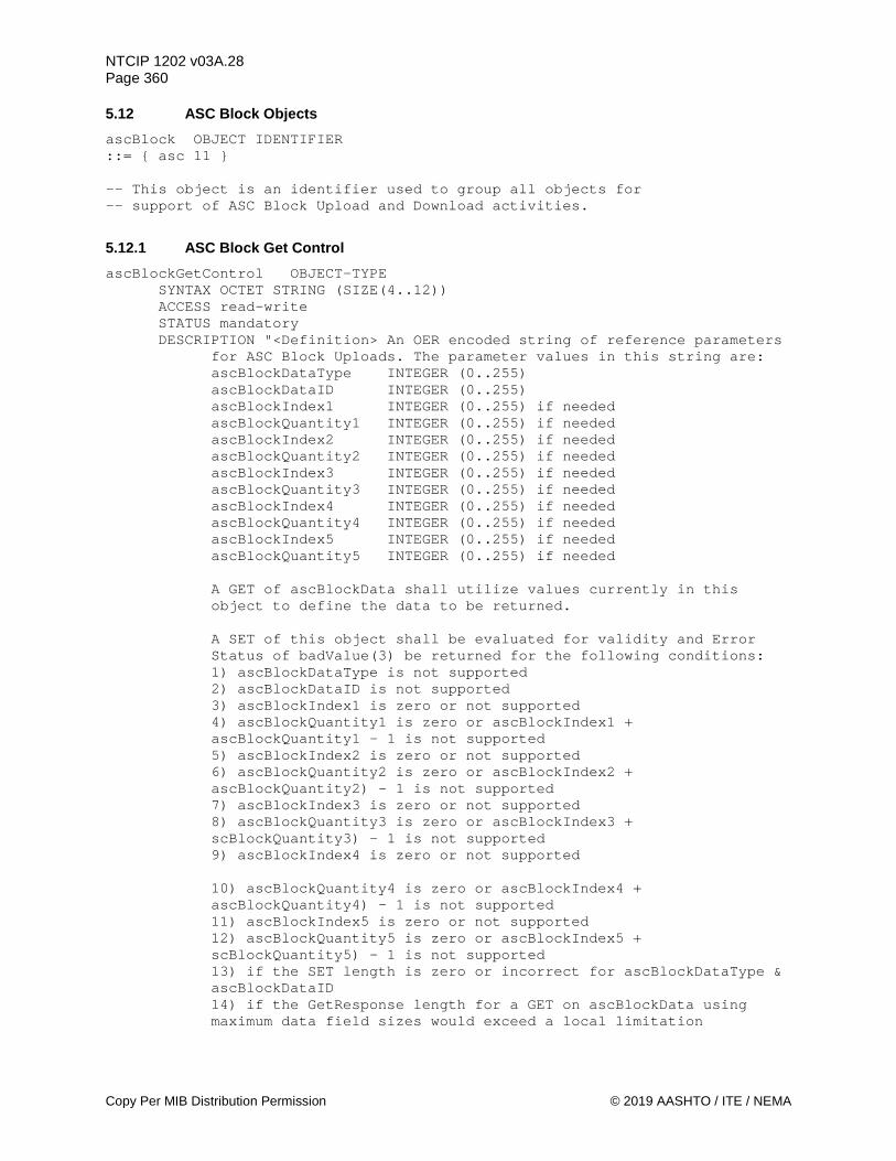
NTCIP 1202 v03A.28 Page 360
Copy Per MIB Distribution Permission © 2019 AASHTO / ITE / NEMA
5.12 ASC Block Objects ascBlock OBJECT IDENTIFIER ::= { asc 11 } -- This object is an identifier used to group all objects for -- support of ASC Block Upload and Download activities.
5.12.1 ASC Block Get Control ascBlockGetControl OBJECT-TYPE
SYNTAX OCTET STRING (SIZE(4..12)) ACCESS read-write STATUS mandatory DESCRIPTION "<Definition> An OER encoded string of reference parameters
for ASC Block Uploads. The parameter values in this string are: ascBlockDataType INTEGER (0..255) ascBlockDataID INTEGER (0..255) ascBlockIndex1 INTEGER (0..255) if needed ascBlockQuantity1 INTEGER (0..255) if needed ascBlockIndex2 INTEGER (0..255) if needed ascBlockQuantity2 INTEGER (0..255) if needed ascBlockIndex3 INTEGER (0..255) if needed ascBlockQuantity3 INTEGER (0..255) if needed ascBlockIndex4 INTEGER (0..255) if needed ascBlockQuantity4 INTEGER (0..255) if needed ascBlockIndex5 INTEGER (0..255) if needed ascBlockQuantity5 INTEGER (0..255) if needed
A GET of ascBlockData shall utilize values currently in this object to define the data to be returned.
A SET of this object shall be evaluated for validity and Error Status of badValue(3) be returned for the following conditions: 1) ascBlockDataType is not supported 2) ascBlockDataID is not supported 3) ascBlockIndex1 is zero or not supported 4) ascBlockQuantity1 is zero or ascBlockIndex1 + ascBlockQuantity1 - 1 is not supported 5) ascBlockIndex2 is zero or not supported 6) ascBlockQuantity2 is zero or ascBlockIndex2 + ascBlockQuantity2) - 1 is not supported 7) ascBlockIndex3 is zero or not supported 8) ascBlockQuantity3 is zero or ascBlockIndex3 + scBlockQuantity3) - 1 is not supported 9) ascBlockIndex4 is zero or not supported
10) ascBlockQuantity4 is zero or ascBlockIndex4 + ascBlockQuantity4) - 1 is not supported 11) ascBlockIndex5 is zero or not supported 12) ascBlockQuantity5 is zero or ascBlockIndex5 + scBlockQuantity5) - 1 is not supported 13) if the SET length is zero or incorrect for ascBlockDataType & ascBlockDataID 14) if the GetResponse length for a GET on ascBlockData using maximum data field sizes would exceed a local limitation

NTCIP 1202 v03A.28 Page 361
© 2019 AASHTO / ITE / NEMA Copy Per MIB Distribution Permission
When this validity check fails, ascBlockErrorStatus shall be set equal to the Bullet Value above that generated the error.
<Object Identifier> 1.3.6.1.4.1.1206.4.2.1.11.1 <Unit> "
::= { ascBlock 1 }
5.12.2 ASC Block Data ascBlockData OBJECT-TYPE
SYNTAX OCTET STRING (SIZE(6..65535)) ACCESS read-write STATUS mandatory DESCRIPTION "<Definition> An OER encoded string used for uploading and
downloading ASC parameters. See SECTION 6 for encoding and decoding the block. A SET on this object shall require the use of 'dbCreateTransaction' defined in NTCIP 1201 Clause 2.3.1.
A SET of this object shall be evaluated for validity and Error Status of badValue(3) be returned for the following conditions: 1) ascBlockDataType is not supported 2) ascBlockDataID is not supported 3) ascBlockIndex1 is zero or not supported 4) ascBlockQuantity1 is zero or ascBlockIndex1 + ascBlockQuantity1 - 1 is not supported 5) ascBlockIndex2 is zero or not supported 6) ascBlockQuantity2 is zero or ascBlockIndex2 + ascBlockQuantity2) - 1 is not supported 7) ascBlockIndex3 is zero or not supported 8) ascBlockQuantity3 is zero or ascBlockIndex3 + ascBlockQuantity3) - 1 is not supported 9) ascBlockIndex4 is zero or not supported 10) ascBlockQuantity4 is zero or ascBlockIndex4 + ascBlockQuantity4) - 1 is not supported 11) ascBlockIndex5 is zero or not supported 12) ascBlockQuantity5 is zero or ascBlockIndex5 + ascBlockQuantity5) - 1 is not supported 13) if the SET length is zero or incorrect for ascBlockDataType & ascBlockDataID 14) if the SET (SEQUENCE OF) value is incorrect. When this validity check fails, ascBlockErrorStatus shall be set equal to the Bullet Value above that generated the error.
A SET that includes an unsupported value for a supported data element shall return an Error Status of badValue(3) and ascBlockErrorStatus shall be set equal to: (data Sequence # * 100) + data Element #
A SET that includes a non-zero or non-null value in the position of an unsupported data element shall return an Error Status of badValue(3) and ascBlockErrorStatus shall be set equal to: (data Sequence # * 100) + data Element #
A GET on this object shall utilize values currently in ascBlockGetControl to define the data to be returned. When ascBlockGetControl has invalid data, an Error STATUS of badValue(3) shall be returned.

NTCIP 1202 v03A.28 Page 362
Copy Per MIB Distribution Permission © 2019 AASHTO / ITE / NEMA
A GET shall return a zero or null value in the position of an unsupported object.
<Object Identifier> 1.3.6.1.4.1.1206.4.2.1.11.2 <Unit> "
::= { ascBlock 2 }
5.12.3 ASC Block Error Status ascBlockErrorStatus OBJECT-TYPE
SYNTAX INTEGER (0..65535) ACCESS read-only STATUS mandatory DESCRIPTION "<Definition> This object defines the data element within
ascBlockGetControl or ascBlockData that caused a badValue(3) ErrorStatus. This object should equal zero after any successful SET to ascBlockGetControl or ascBlockData.
<Object Identifier> 1.3.6.1.4.1.1206.4.2.1.11.3" ::= { ascBlock 3 }
5.13 Cabinet Parameters cabinetEnvironment OBJECT IDENTIFIER ::= { asc 12 } -- This node contains objects that monitor and control the cabinet -- environment functions for this device.
5.13.1 Maximum Cabinet Environmental Monitoring Devices maxCabinetEnvironDevices OBJECT-TYPE
SYNTAX INTEGER (1..255) ACCESS read-only STATUS mandatory DESCRIPTION "<Definition> The maximum number of environmental
monitoring devices this CU supports. This object indicates the maximum rows which shall appear in the cabinetEnvironDevicesTable object.
<Object Identifier> 1.3.6.1.4.1.1206.4.2.1.12.1 <Unit> number"
::= { cabinetEnvironment 1 }
5.13.2 Cabinet Environmental Devices Table cabinetEnvironDevicesTable OBJECT-TYPE
SYNTAX SEQUENCE OF CabinetEnvironDeviceEntry ACCESS not-accessible STATUS mandatory DESCRIPTION "<Definition> A table containing the parameters of the
environmental monitoring devices contained in the cabinet. The number of rows in this table is equal to the maxCabinetEnvironDevices object.
<Object Identifier> 1.3.6.1.4.1.1206.4.2.1.12.2 <TableType> static"
::= { cabinetEnvironment 2 }
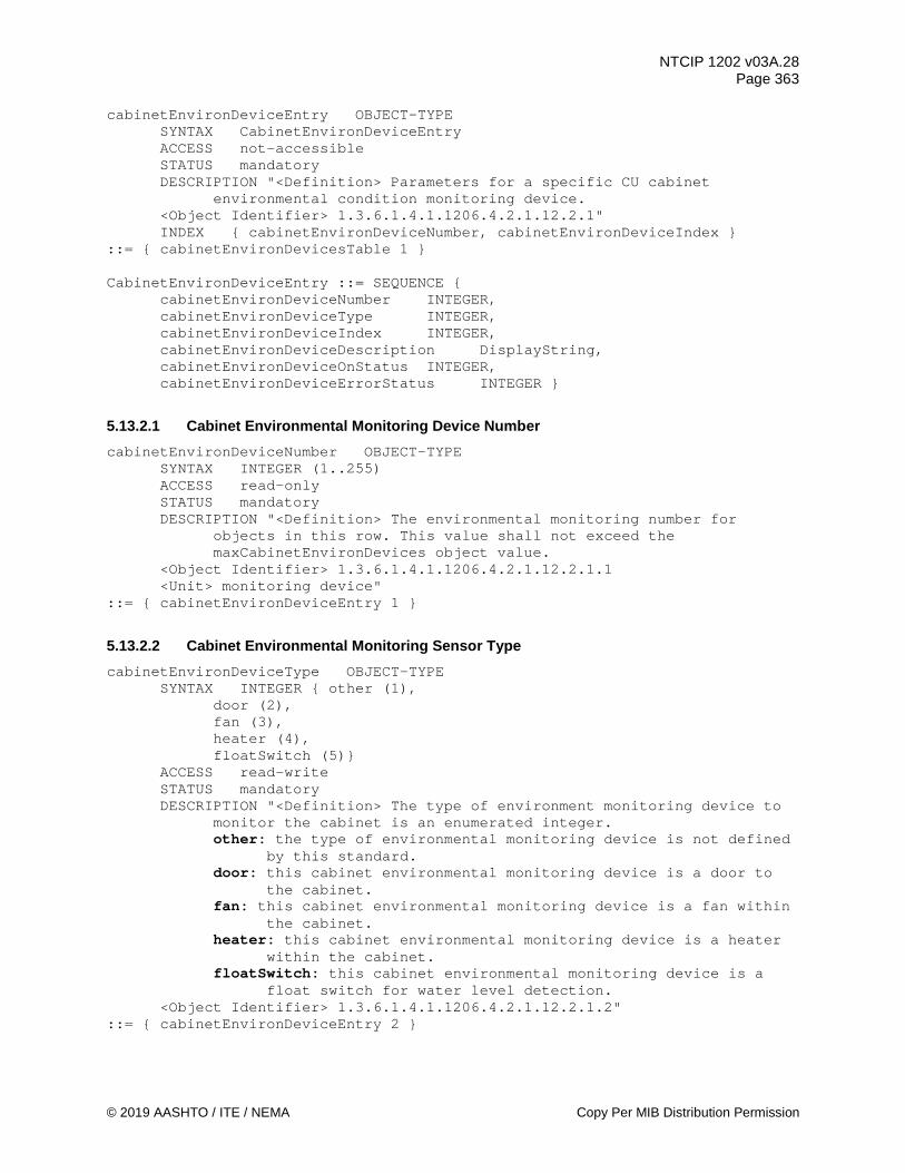
NTCIP 1202 v03A.28 Page 363
© 2019 AASHTO / ITE / NEMA Copy Per MIB Distribution Permission
cabinetEnvironDeviceEntry OBJECT-TYPE SYNTAX CabinetEnvironDeviceEntry ACCESS not-accessible STATUS mandatory DESCRIPTION "<Definition> Parameters for a specific CU cabinet
environmental condition monitoring device. <Object Identifier> 1.3.6.1.4.1.1206.4.2.1.12.2.1" INDEX { cabinetEnvironDeviceNumber, cabinetEnvironDeviceIndex }
::= { cabinetEnvironDevicesTable 1 } CabinetEnvironDeviceEntry ::= SEQUENCE {
cabinetEnvironDeviceNumber INTEGER, cabinetEnvironDeviceType INTEGER, cabinetEnvironDeviceIndex INTEGER, cabinetEnvironDeviceDescription DisplayString, cabinetEnvironDeviceOnStatus INTEGER, cabinetEnvironDeviceErrorStatus INTEGER }
5.13.2.1 Cabinet Environmental Monitoring Device Number cabinetEnvironDeviceNumber OBJECT-TYPE
SYNTAX INTEGER (1..255) ACCESS read-only STATUS mandatory DESCRIPTION "<Definition> The environmental monitoring number for
objects in this row. This value shall not exceed the maxCabinetEnvironDevices object value.
<Object Identifier> 1.3.6.1.4.1.1206.4.2.1.12.2.1.1 <Unit> monitoring device"
::= { cabinetEnvironDeviceEntry 1 }
5.13.2.2 Cabinet Environmental Monitoring Sensor Type cabinetEnvironDeviceType OBJECT-TYPE
SYNTAX INTEGER { other (1), door (2), fan (3), heater (4), floatSwitch (5)}
ACCESS read-write STATUS mandatory DESCRIPTION "<Definition> The type of environment monitoring device to
monitor the cabinet is an enumerated integer. other: the type of environmental monitoring device is not defined
by this standard. door: this cabinet environmental monitoring device is a door to
the cabinet. fan: this cabinet environmental monitoring device is a fan within
the cabinet. heater: this cabinet environmental monitoring device is a heater
within the cabinet. floatSwitch: this cabinet environmental monitoring device is a
float switch for water level detection. <Object Identifier> 1.3.6.1.4.1.1206.4.2.1.12.2.1.2"
::= { cabinetEnvironDeviceEntry 2 }

NTCIP 1202 v03A.28 Page 364
Copy Per MIB Distribution Permission © 2019 AASHTO / ITE / NEMA
5.13.2.3 Cabinet Environmental Monitoring Device Index cabinetEnvironDeviceIndex OBJECT-TYPE
SYNTAX INTEGER (1..255) ACCESS read-only STATUS mandatory DESCRIPTION "<Definition> The index for the cabinetEnvironDeviceType.
This value allows support for multiple sensors of a specific environment monitoring device type.
<Object Identifier> 1.3.6.1.4.1.1206.4.2.1.12.2.1.3" ::= { cabinetEnvironDeviceEntry 3 }
5.13.2.4 Cabinet Environmental Monitoring Device Description cabinetEnvironDeviceDescription OBJECT-TYPE
SYNTAX DisplayString (SIZE (0..64)) ACCESS read-write STATUS mandatory DESCRIPTION "<Definition> Human-readable description of the cabinet
environmental device. This value should provide enough information for maintenance personnel to identify the type (door, fan, heater, etc.) and physical location of the device defined in this row within the CU or CU cabinet.
<Object Identifier> 1.3.6.1.4.1.1206.4.2.1.12.2.1.4" ::= { cabinetEnvironDeviceEntry 4 }
5.13.2.5 Cabinet Environmental Monitoring Device On Status cabinetEnvironDeviceOnStatus OBJECT-TYPE
SYNTAX INTEGER { true (1), false (2) }
ACCESS read-only STATUS mandatory DESCRIPTION "<Definition> Indicates if this environmental monitoring
device is on/open or off/closed. A bit orientation of 1 (true) indicates the environmental monitoring device is on, or in the case of a door, the door is open. A value of 0 (false) indicates this environmental monitoring device is off, or in the case of a door, the door is closed.
<Object Identifier> 1.3.6.1.4.1.1206.4.2.1.12.2.1.5" ::= { cabinetEnvironDeviceEntry 5 }
5.13.2.6 Cabinet Environmental Monitoring Device Error Status cabinetEnvironDeviceErrorStatus OBJECT-TYPE
SYNTAX INTEGER { other (1), --not used noError (2), fail (3), notMonitored (4) } ACCESS read-only STATUS mandatory DESCRIPTION "<Definition> Indicates the current status of the
environmental monitoring device. <Object Identifier> 1.3.6.1.4.1.1206.4.2.1.12.2.1.6"
::= { cabinetEnvironDeviceEntry 6 }

NTCIP 1202 v03A.28 Page 365
© 2019 AASHTO / ITE / NEMA Copy Per MIB Distribution Permission
5.13.3 Maximum Number of Cabinet Temperature Sensors maxCabinetTempSensors OBJECT-TYPE
SYNTAX INTEGER (0..16) ACCESS read-only STATUS mandatory DESCRIPTION "<Definition> Indicates the number of rows in the
cabinetTempSensorStatusTable. <Unit> temperature sensors <Object Identifier> 1.3.6.1.4.1.1206.4.2.1.12.3"
::= { cabinetEnvironment 3 }
5.13.4 Cabinet Temperature Sensor Status Table cabinetTempSensorStatusTable OBJECT-TYPE
SYNTAX SEQUENCE OF CabinetTempSensorStatusEntry ACCESS not-accessible STATUS mandatory DESCRIPTION "<Definition> A table containing status information for
each temperature sensor within a CU and CU cabinet. <Table Type> static <Object Identifier> 1.3.6.1.4.1.1206.4.2.1.12.4"
::= { cabinetEnvironment 4 } cabinetTempSensorStatusEntry OBJECT-TYPE
SYNTAX CabinetTempSensorStatusEntry ACCESS not-accessible STATUS mandatory DESCRIPTION "<Definition> An entry in the cabinet temperature sensor
status table. <Object Identifier> 1.3.6.1.4.1.1206.4.2.1.12.4.1" INDEX { cabinetTempSensorIndex }
::= { cabinetTempSensorStatusTable 1} CabinetTempSensorStatusEntry ::= SEQUENCE {
cabinetTempSensorIndex INTEGER, cabinetTempSensorDescription DisplayString, cabinetTempSensorCurrentReading INTEGER, cabinetTempSensorHighThreshold INTEGER, cabinetTempSensorLowThreshold INTEGER, cabinetTempSensorStatus INTEGER }
5.13.4.1 Cabinet Temperature Sensor Index cabinetTempSensorIndex OBJECT-TYPE
SYNTAX INTEGER (1..16) ACCESS read-only STATUS mandatory DESCRIPTION "<Definition> Index of the cabinet temperature sensor
status table. This value shall not exceed maxCabinetTempSensors. <Object Identifier> 1.3.6.1.4.1.1206.4.2.1.12.4.1.1"
::= { cabinetTempSensorStatusEntry 1 }
5.13.4.2 Cabinet Temperature Sensor Description cabinetTempSensorDescription OBJECT-TYPE
SYNTAX DisplayString (SIZE (0..64))
NTCIP 1202 v03A.28 Page 366
Copy Per MIB Distribution Permission © 2019 AASHTO / ITE / NEMA
ACCESS read-write STATUS mandatory DESCRIPTION "<Definition> Human-readable description of the temperature
sensor. This value should provide enough information for maintenance personnel to identify the physical location of the temperature sensor within the CU or CU cabinet.
<Object Identifier> 1.3.6.1.4.1.1206.4.2.1.12.4.1.2" ::= { cabinetTempSensorStatusEntry 2 }
5.13.4.3 Cabinet Temperature Sensor Current Reading cabinetTempSensorCurrentReading OBJECT-TYPE
SYNTAX INTEGER (-128..127) ACCESS read-only STATUS mandatory DESCRIPTION "<Definition> Indicates the current reading, in degrees
Celsius, of the temperature sensor. <Valid Value Rule> The value -127 shall indicate a temperature of -127
degrees Celsius or lower. The value 127 shall indicate a temperature of 127 degrees Celsius or higher. The value -128 shall indicate an error condition or missing value.
<Object Identifier> 1.3.6.1.4.1.1206.4.2.1.12.4.1.3 <Unit> degrees Celsius" DEFVAL { -56 }
::= { cabinetTempSensorStatusEntry 3 }
5.13.4.4 Cabinet Temperature Sensor High Warning Temperature cabinetTempSensorHighThreshold OBJECT-TYPE
SYNTAX INTEGER (-128..127) ACCESS read-write STATUS mandatory DESCRIPTION "<Definition> Indicates the high value of the temperature,
in degrees Celsius, associated with this temperature sensor above which would generate a warning (Bit 3 of unitAlarmStatus4). This value should not be lower than the value of the cabinetTempSensorLowThreshold object.
<Object Identifier> 1.3.6.1.4.1.1206.4.2.1.12.4.1.4 <Unit>degrees Celsius"
::= { cabinetTempSensorStatusEntry 4 }
5.13.4.5 Cabinet Temperature Sensor Low Warning Temperature cabinetTempSensorLowThreshold OBJECT-TYPE
SYNTAX INTEGER (-128..127) ACCESS read-write STATUS mandatory DESCRIPTION "<Definition> Indicates the low value of the temperature,
in degrees Celsius, associated with this temperature sensor below which would generate a warning (Bit 3 of unitAlarmStatus4). This value should not be higher than the value of the cabinetTempSensorHighThreshold object.
<Object Identifier> 1.3.6.1.4.1.1206.4.2.1.12.4.1.5 <Unit>degrees Celsius"
::= { cabinetTempSensorStatusEntry 5 }
NTCIP 1202 v03A.28 Page 367
© 2019 AASHTO / ITE / NEMA Copy Per MIB Distribution Permission
5.13.4.6 Cabinet Temperature Sensor Status cabinetTempSensorStatus OBJECT-TYPE
SYNTAX INTEGER { other (1), noError (2), fail (3) }
ACCESS read-only STATUS mandatory DESCRIPTION "<Definition> Indicates the current status of the indicated
temperature sensor. <Object Identifier> 1.3.6.1.4.1.1206.4.2.1.12.4.1.6"
::= { cabinetTempSensorStatusEntry 6 }
5.13.5 Maximum Number of Humidity Sensors maxCabinetHumiditySensors OBJECT-TYPE
SYNTAX INTEGER (0..16) ACCESS read-only STATUS mandatory DESCRIPTION "<Definition> Indicates the number of rows in the
cabinetHumiditySensorStatusTable. <Unit> humidity sensors <Object Identifier> 1.3.6.1.4.1.1206.4.2.1.12.5"
::= { cabinetEnvironment 5 }
5.13.6 Cabinet Humidity Sensor Status Table cabinetHumiditySensorStatusTable OBJECT-TYPE
SYNTAX SEQUENCE OF CabinetHumiditySensorStatusEntry ACCESS not-accessible STATUS mandatory DESCRIPTION "<Definition> A table containing status information for
each humidity sensor within a CU cabinet. <Table Type> static <Object Identifier> 1.3.6.1.4.1.1206.4.2.1.12.6"
::= { cabinetEnvironment 6 } cabinetHumiditySensorStatusEntry OBJECT-TYPE
SYNTAX CabinetHumiditySensorStatusEntry ACCESS not-accessible STATUS mandatory DESCRIPTION "<Definition> An entry in the humidity sensor status table. <Object Identifier> 1.3.6.1.4.1.1206.4.2.1.12.6.1" INDEX { cabinetHumiditySensorIndex } ::= { cabinetHumiditySensorStatusTable 1}
CabinetHumiditySensorStatusEntry ::= SEQUENCE {
cabinetHumiditySensorIndex INTEGER, cabinetHumiditySensorDescription DisplayString, cabinetHumiditySensorCurrentReading INTEGER, cabinetHumidityThreshold INTEGER, cabinetHumiditySensorStatus INTEGER }
5.13.6.1 Cabinet Humidity Sensor Index cabinetHumiditySensorIndex OBJECT-TYPE
SYNTAX INTEGER (1..16)

NTCIP 1202 v03A.28 Page 368
Copy Per MIB Distribution Permission © 2019 AASHTO / ITE / NEMA
ACCESS read-only STATUS mandatory DESCRIPTION "<Definition> Index of the humidity sensor status table.
This value does not exceed maxCabinetHumiditySensors. <Object Identifier> 1.3.6.1.4.1.1206.4.2.1.12.6.1.1"
::= { cabinetHumiditySensorStatusEntry 1 }
5.13.6.2 Cabinet Humidity Sensor Description cabinetHumiditySensorDescription OBJECT-TYPE
SYNTAX DisplayString (SIZE (0..64)) ACCESS read-write STATUS mandatory DESCRIPTION "<Definition> Human-readable description of the humidity
sensor. This value should provide enough information for maintenance personnel to identify the physical location of the humidity sensor within the CU cabinet.
<Object Identifier> 1.3.6.1.4.1.1206.4.2.1.12.6.1.2" ::= { cabinetHumiditySensorStatusEntry 2 }
5.13.6.3 Cabinet Humidity Sensor Current Reading cabinetHumiditySensorCurrentReading OBJECT-TYPE
SYNTAX INTEGER (0..101) ACCESS read-only STATUS mandatory DESCRIPTION "<Definition> Indicates the current reading of the humidity
sensor, in percent relative humidity. <Valid Value Rule> The value 101 shall indicate an error condition or
missing value. <Object Identifier> 1.3.6.1.4.1.1206.4.2.1.12.6.1.3 <Unit>percent relative humidity" DEFVAL { 101 }
::= { cabinetHumiditySensorStatusEntry 3 }
5.13.6.4 Cabinet Humidity Sensor Threshold cabinetHumidityThreshold OBJECT-TYPE
SYNTAX INTEGER (0..101) ACCESS read-write STATUS mandatory DESCRIPTION "<Definition> Indicates the relative humidity, in percent,
within the CU cabinet above which the humidity threshold alarm shall be activated (Bit 3 of unitAlarmStatus4).
<Object Identifier> 1.3.6.1.4.1.1206.4.2.1.12.6.1.4 <Unit> percent humidity"
::= { cabinetHumiditySensorStatusEntry 4 }
5.13.6.5 Cabinet Humidity Sensor Status cabinetHumiditySensorStatus OBJECT-TYPE
SYNTAX INTEGER { other (1), --not used noError (2), fail (3) }
ACCESS read-only STATUS mandatory
NTCIP 1202 v03A.28 Page 369
© 2019 AASHTO / ITE / NEMA Copy Per MIB Distribution Permission
DESCRIPTION "<Definition> Indicates the current status of the indicated humidity sensor.
<Object Identifier> 1.3.6.1.4.1.1206.4.2.1.12.6.1.5" ::= { cabinetHumiditySensorStatusEntry 5 }
5.13.7 Power Source ascPowerSource OBJECT-TYPE
SYNTAX INTEGER { unknown (1), other (2), acLine (3), generator (4), solar (5), battery-UPS (6), dc48VPower (7), dc24Vpower (8) }
ACCESS read-only STATUS mandatory DESCRIPTION "<Definition> Integer value that indicates the current
primary power source for the CU cabinet, expressed as an enumerated integer. unknown: the current primary power source is unknown or cannot
be determined. other: the current primary power source is not defined by
this standard. acLine: the current primary power source is in-line AC power. generator: the current primary power source is a generator that
is operational. solar: the current primary power source is solar equipment, that
may be have a battery as an intermediary. battery-UPS: the current primary power source is a battery
or UPS with no significant charging occurring. dc48VPower: the current primary power source is 48 volts DC
directly into the cabinet. dc24VPower: the current primary power source is 48 volts DC
directly into the cabinet. <Object Identifier> 1.3.6.1.4.1.1206.4.2.1.12.7" DEFVAL { unknown }
::= { cabinetEnvironment 7 }
5.13.8 Line Volts ascLineVolts OBJECT-TYPE
SYNTAX INTEGER (0..6001) ACCESS read-only STATUS mandatory DESCRIPTION "<Definition> Indicates the voltage, in 0.1 RMS volt units,
measured on the incoming power line for the CU. This object shall only be used to indicate A/C power conditions. If the line power is DC, this object shall not apply (i.e., this object will either not be supported or this object will have a value of 3001).
<Valid Value Rule> Values 0 through 5999 shall indicate valid values. The value 6000 shall mean a voltage of 600.0 Vrms or greater. The value of 6001 shall indicate an error condition or missing value.
<Object Identifier> 1.3.6.1.4.1.1206.4.2.1.12.8 <Unit>0.1 Volts Root Mean Squared (Vrms)"

NTCIP 1202 v03A.28 Page 370
Copy Per MIB Distribution Permission © 2019 AASHTO / ITE / NEMA
DEFVAL { 6001 } ::= { cabinetEnvironment 8 }
5.13.9 ATC Cabinet LED Displays atccLEDMode OBJECT-TYPE
SYNTAX INTEGER { other (1), on (2), off (3) }
ACCESS read-write STATUS mandatory DESCRIPTION "<Definition> Object that allows control of the LED
displays within an ATC cabinet. other: LED mode of operation is not defined by this standard. on: ATCC module LEDs operate normally (e.g., full brightness and
flashing are prescribed by module documentation). off: ATCC module LEDs are off (sleep) when all cabinet door(s)
are closed. All other values are RESERVED.
<Object Identifier> 1.3.6.1.4.1.1206.4.2.1.12.9" ::= { cabinetEnvironment 9 }
5.14 I/O Mapping ascIOmapping OBJECT IDENTIFIER ::= { asc 13 } -- This node contains objects that configure, monitor or control input and -- output mapping in the ASC
5.14.1 I/O Mapping Control ascIOmapControl OBJECT IDENTIFIER ::= { ascIOmapping 1 } -- This node contains objects that control the current I/O map
5.14.1.1 Maximum Number of I/O Maps ascIOmaxMaps OBJECT-TYPE SYNTAX INTEGER (1..255) ACCESS read-only STATUS mandatory DESCRIPTION "<Definition> This object contains the maximum number of I/O maps this ASC supports. This object indicates the number of rows in the ascIOmapsTable. <Object Identifier> 1.3.6.1.4.1.1206.4.2.1.13.1.1" ::= { ascIOmapControl 1 }
5.14.1.2 Active I/O Map ascIOactiveMap OBJECT-TYPE SYNTAX INTEGER (1..255) ACCESS read-write STATUS mandatory
NTCIP 1202 v03A.28 Page 371
© 2019 AASHTO / ITE / NEMA Copy Per MIB Distribution Permission
DESCRIPTION "<Definition> This object selects the active I/O map. This object has to be changed as part of a 1201 Database Transaction (see the dbCreateTransaction object). A Database Transaction that changes this object or edits the currently active I/O map has to satisfy the activation requirements in ascIOactivateRequirement at the time dbCreateTransaction is set to verify (3) for the transaction to successfully verify. The value of this object cannot exceed the value of ascIOmaxMaps. <Object Identifier> 1.3.6.1.4.1.1206.4.2.1.13.1.2" DEFVAL { 1 } ::= { ascIOmapControl 2 }
5.14.1.3 Conditions for Activating New I/O Map ascIOactivateRequirement OBJECT-TYPE SYNTAX INTEGER (0..255) ACCESS read-only STATUS mandatory DESCRIPTION "<Definition> This object returns the conditions under which an ASC will confirm a DB transaction that activates a new I/O map or edits the currently active I/O map. The requirements are selected in a bitmap format: Bit 0 - cabinetDoorOpen -- I/O input cabinetDoorOpen active Bit 1 - inFlash -- in any flash state Bit 2 – allRedFlash -- in programmed all red flash Bit 3 - cabinetFlash -- in CVM flash, input localFlashSense active Bit 4 – restart -- changes take effect only after a restart Bit 5 – reserved Bit 6 – reserved Bit 7 - reserved
Note: if all I/O mapping values being set are the same as the current values, the DB transaction shall succeed without requiring any conditions set by this object.
<Object Identifier> 1.3.6.1.4.1.1206.4.2.1.13.1.3" ::= { ascIOmapControl 3 }
5.14.2 I/O Maps Maximum Inputs ascIOmapMaxInputs OBJECT-TYPE SYNTAX INTEGER (1..65535) ACCESS read-only STATUS mandatory DESCRIPTION "<Definition> This object contains the maximum number of I/O mapping input functions this ASC supports. This object indicates the number of rows in the ascIOinputMapTable.
<Object Identifier> 1.3.6.1.4.1.1206.4.2.1.13.2" ::= { ascIOmapping 2 }
5.14.3 I/O Maps Maximum Outputs ascIOmapMaxOutputs OBJECT-TYPE SYNTAX INTEGER (1..65535)
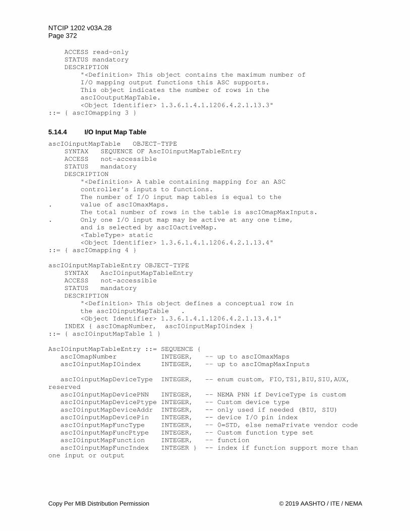
NTCIP 1202 v03A.28 Page 372
Copy Per MIB Distribution Permission © 2019 AASHTO / ITE / NEMA
ACCESS read-only STATUS mandatory DESCRIPTION "<Definition> This object contains the maximum number of I/O mapping output functions this ASC supports. This object indicates the number of rows in the ascIOoutputMapTable. <Object Identifier> 1.3.6.1.4.1.1206.4.2.1.13.3" ::= { ascIOmapping 3 }
5.14.4 I/O Input Map Table ascIOinputMapTable OBJECT-TYPE SYNTAX SEQUENCE OF AscIOinputMapTableEntry ACCESS not-accessible STATUS mandatory DESCRIPTION "<Definition> A table containing mapping for an ASC controller’s inputs to functions. The number of I/O input map tables is equal to the . value of ascIOmaxMaps. The total number of rows in the table is ascIOmapMaxInputs. . Only one I/O input map may be active at any one time, and is selected by ascIOactiveMap. <TableType> static <Object Identifier> 1.3.6.1.4.1.1206.4.2.1.13.4" ::= { ascIOmapping 4 } ascIOinputMapTableEntry OBJECT-TYPE SYNTAX AscIOinputMapTableEntry ACCESS not-accessible STATUS mandatory DESCRIPTION "<Definition> This object defines a conceptual row in the ascIOinputMapTable . <Object Identifier> 1.3.6.1.4.1.1206.4.2.1.13.4.1" INDEX { ascIOmapNumber, ascIOinputMapIOindex } ::= { ascIOinputMapTable 1 } AscIOinputMapTableEntry ::= SEQUENCE { ascIOmapNumber INTEGER, -- up to ascIOmaxMaps ascIOinputMapIOindex INTEGER, -- up to ascIOmapMaxInputs ascIOinputMapDeviceType INTEGER, -- enum custom, FIO,TS1,BIU,SIU,AUX, reserved ascIOinputMapDevicePNN INTEGER, -- NEMA PNN if DeviceType is custom ascIOinputMapDevicePtype INTEGER, -- Custom device type ascIOinputMapDeviceAddr INTEGER, -- only used if needed (BIU, SIU) ascIOinputMapDevicePin INTEGER, -- device I/O pin index ascIOinputMapFuncType INTEGER, -- 0=STD, else nemaPrivate vendor code ascIOinputMapFuncPtype INTEGER, -- Custom function type set ascIOinputMapFunction INTEGER, -- function ascIOinputMapFuncIndex INTEGER } -- index if function support more than one input or output

NTCIP 1202 v03A.28 Page 373
© 2019 AASHTO / ITE / NEMA Copy Per MIB Distribution Permission
5.14.4.1 I/O Map Number ascIOmapNumber OBJECT-TYPE SYNTAX INTEGER (1..255) ACCESS read-only STATUS mandatory DESCRIPTION "<Definition> The value of this object shall not exceed the ascIOmaxMaps value. <Object Identifier> 1.3.6.1.4.1.1206.4.2.1.13.4.1.1" ::= { ascIOinputMapTableEntry 1 }
5.14.4.2 I/O Input Map Index ascIOinputMapIOindex OBJECT-TYPE SYNTAX INTEGER (1..65535) ACCESS read-only STATUS mandatory DESCRIPTION "<Definition> The I/O index for this row of the table. The range will not exceed ascIOmapMaxInputs. <Object Identifier> 1.3.6.1.4.1.1206.4.2.1.13.4.1.2" ::= { ascIOinputMapTableEntry 2 }
5.14.4.3 I/O Input Map Device Type ascIOinputMapDeviceType OBJECT-TYPE SYNTAX INTEGER { unused (1), custom (2), fio (3), ts1 (4), biu (5), siu (6), aux (7) } ACCESS read-write STATUS mandatory DESCRIPTION "<Definition> This object is an selects the device type for this row of the table. A value of unused (1) means that this row of the table is unused (all values of ascIOinputMapIOindex up to ascIOmapMaxInputs may not be needed by every mapping). A custom type is a manufacturer defined device which also requires a ascIOinputMapDevicePNN and a ascIOinputMapDevicePtype to fully specify the device. Values > 7 are reserved for future device types. <Object Identifier> 1.3.6.1.4.1.1206.4.2.1.13.4.1.3" ::= { ascIOinputMapTableEntry 3 }
5.14.4.4 I/O Input Map Custom Device Manufacturer ID ascIOinputMapDevicePNN OBJECT-TYPE SYNTAX INTEGER (0..65535) ACCESS read-write STATUS mandatory DESCRIPTION

NTCIP 1202 v03A.28 Page 374
Copy Per MIB Distribution Permission © 2019 AASHTO / ITE / NEMA
"<Definition> The object is used to further define a device type when ascIOinputMapDeviceType is custom (1). The value of this object will be the manufacturer's Private Node Number (PNN) as assigned by NEMA (1.3.6.1.4.1.1206.3.PNN). This is the same identifier used for ASC custom blocks. <Object Identifier> 1.3.6.1.4.1.1206.4.2.1.13.4.1.4" ::= { ascIOinputMapTableEntry 4 }
5.14.4.5 I/O Input Map Custom Device Type ascIOinputMapDevicePtype OBJECT-TYPE SYNTAX INTEGER (0..255) ACCESS read-write STATUS mandatory DESCRIPTION "<Definition> The object is used to further define a device type when ascIOinputMapDeviceType is custom (1). The value of this object will identify a custom device type unique to the manufacturer specified by ascIOinputMapDevicePNN. <Object Identifier> 1.3.6.1.4.1.1206.4.2.1.13.4.1.5" ::= { ascIOinputMapTableEntry 5 }
5.14.4.6 I/O Input Map Device Address ascIOinputMapDeviceAddr OBJECT-TYPE SYNTAX INTEGER (0..255) ACCESS read-write STATUS mandatory DESCRIPTION "<Definition> An address for the device at this table row. The address is used for devices like BIUs and SIUs that require an address. The value should be zero if the address is not needed for this row. If the ascIOinputMapDeviceType is biu (4), the address values are: 1 - Traffic Facilities BIU #1 2 - Traffic Facilities BIU #2 3 - Traffic Facilities BIU #3 4 - Traffic Facilities BIU #4 5-8 - reserved 9 - Detector BIU #1 10 - Detector BIU #2 11 - Detector BIU #3 12 - Detector BIU #4 13-16 - reserved Note that these values are the BIU SDLC address + 1. If the ascIOinputMapDeviceType is siu (5), the address values are: 1 - reserved 2 - 14-pack output SIU position 1 3 - reserved 4 - 14-pack output SIU position 3 5 - 6-pack output SIU position 4 6 - 6-pack output SIU position 1 7 - 6-pack output SIU position 2

NTCIP 1202 v03A.28 Page 375
© 2019 AASHTO / ITE / NEMA Copy Per MIB Distribution Permission
8 - 6-pack output SIU position 3 9 - reserved 10 - input SIU #1 11 - input SIU #2 12 - input SIU #3 13 - input SIU #4 14 - input SIU #5 15 - reserved Note that these values are the SIU SDLC address + 1. <Object Identifier> 1.3.6.1.4.1.1206.4.2.1.13.4.1.6" ::= { ascIOinputMapTableEntry 6 }
5.14.4.7 I/O Input Map Device Pin ascIOinputMapDevicePin OBJECT-TYPE SYNTAX INTEGER (0..255) ACCESS read-write STATUS mandatory DESCRIPTION "<Definition> An index for the I/O pin at this table row. The range for this value will depend upon the value of other objects in the row. The range for ascIOinputMapDeviceType: fio (3) pin range is AscIOmapFIOinputs ts1 (4) pin range is AscIOmapTS1inputs biu (5) pin range is AscIOmapBIUinputs siu (6) pin range is AscIOmapSIUinputs aux (7) pin range is AscIOmapAUXinputs The range for a custom device type will be determined by the manufacturer defining it. <Object Identifier> 1.3.6.1.4.1.1206.4.2.1.13.4.1.7" ::= { ascIOinputMapTableEntry 7 }
5.14.4.8 I/O Input Map Function Type ascIOinputMapFuncType OBJECT-TYPE SYNTAX INTEGER (0..65535) ACCESS read-write STATUS mandatory DESCRIPTION "<Definition> This object selects the function type for this row of the table. A value of 0 references the standard input functions defined by AscIOinputType and the ascIOinputMapFunction. Any other value is a manufacturer's Private Node Number (PNN) as assigned by NEMA (1.3.6.1.4.1.1206.3.PNN). In this case the function. is defined by the PNN (the manufacturer), ascIOinputMapFuncPtype (which of the manufacturer's multiple function sets), and the ascIOinputMapFunction. <Object Identifier> 1.3.6.1.4.1.1206.4.2.1.13.4.1.8" ::= { ascIOinputMapTableEntry 8 }
5.14.4.9 I/O Input Map Custom Function Type ascIOinputMapFuncPtype OBJECT-TYPE

NTCIP 1202 v03A.28 Page 376
Copy Per MIB Distribution Permission © 2019 AASHTO / ITE / NEMA
SYNTAX INTEGER (0..255) ACCESS read-write STATUS mandatory DESCRIPTION "<Definition> The object is used to further define a function type when ascIOinputMapFuncType is not zero. The value of this object will identify a custom function type unique to the manufacturer specified by ascIOinputMapDevicePNN. This allows a manufacturer to have multiple sets of functions for their one Private Node Number. <Object Identifier> 1.3.6.1.4.1.1206.4.2.1.13.4.1.9" ::= { ascIOinputMapTableEntry 9 }
5.14.4.10 I/O Input Map Function ascIOinputMapFunction OBJECT-TYPE SYNTAX INTEGER (0..255) ACCESS read-write STATUS mandatory DESCRIPTION "<Definition> This object specifies the function that is mapped to the I/O pin specified by this row. For example, if ascIOinputMapFuncType is zero (standard) then the function could be any AscIOinputType value such as vehicleDetector (51). <Object Identifier> 1.3.6.1.4.1.1206.4.2.1.13.4.1.10" ::= { ascIOinputMapTableEntry 10 }
5.14.4.11 I/O Input Map Function Index ascIOinputMapFuncIndex OBJECT-TYPE SYNTAX INTEGER (0..255) ACCESS read-write STATUS mandatory DESCRIPTION "<Definition> An index for the function at this table row. For example, if ascIOinputMapFuncType is zero (standard) and the ascIOinputMapFunction is vehicleDetector (51) then this index will determine which detector input it is (1 to maxVehicleDetectors). <Object Identifier> 1.3.6.1.4.1.1206.4.2.1.13.4.1.11" ::= { ascIOinputMapTableEntry 11 }
5.14.5 I/O Input Map Status table ascIOinputMapStatusTable OBJECT-TYPE SYNTAX SEQUENCE OF AscIOinputMapStatusTableEntry ACCESS not-accessible STATUS mandatory DESCRIPTION "<Definition> A table containing status for the current mapping for an ASC controller’s inputs. <TableType> static

NTCIP 1202 v03A.28 Page 377
© 2019 AASHTO / ITE / NEMA Copy Per MIB Distribution Permission
<Object Identifier> 1.3.6.1.4.1.1206.4.2.1.13.5" ::= { ascIOmapping 5 } ascIOinputMapStatusTableEntry OBJECT-TYPE SYNTAX AscIOinputMapStatusTableEntry ACCESS not-accessible STATUS mandatory DESCRIPTION "<Definition> This object defines a conceptual row in the ascIOinputMapStatusTable. <Object Identifier> 1.3.6.1.4.1.1206.4.2.1.13.5.1" INDEX { ascIOmapNumber, ascIOinputMapIOindex } ::= { ascIOinputMapStatusTable 1 } AscIOinputMapStatusTableEntry ::= SEQUENCE { ascIOinputMapDevPinDescr OCTET STRING, -- description of input pin ascIOinputMapDevPinStatus INTEGER } -- 0 or 1 for active
5.14.5.1 I/O Input Map Device Pin Description ascIOinputMapDevPinDescr OBJECT-TYPE SYNTAX OCTET STRING (SIZE (32)) ACCESS read-only STATUS mandatory DESCRIPTION "<Definition> This object returns the name of the input pin, such as 'C1-39 Detector 2'. Since the physical pins are determined by the controller hardware, the value is read-only. <Object Identifier> 1.3.6.1.4.1.1206.4.2.1.13.5.1.1" ::= { ascIOinputMapStatusTableEntry 1 }
5.14.5.2 I/O Input Map Device Pin Status ascIOinputMapDevPinStatus OBJECT-TYPE SYNTAX INTEGER (0..1) ACCESS read-only STATUS mandatory DESCRIPTION "<Definition> This object returns the current status of an input pin: inactive/OFF (0) or active/ON (1). <Object Identifier> 1.3.6.1.4.1.1206.4.2.1.13.5.1.2" ::= { ascIOinputMapStatusTableEntry 2 }
5.14.6 I/O Output Map Table ascIOoutputMapTable OBJECT-TYPE SYNTAX SEQUENCE OF AscIOoutputMapTableEntry ACCESS not-accessible STATUS mandatory DESCRIPTION "<Definition> A table containing mapping for an ASC controller’s inputs and outputs to functions. The number of I/O map tables is equal to the value of ascIOmaxMaps. The total number of rows in the table is ascIOmapMaxOutputs.

NTCIP 1202 v03A.28 Page 378
Copy Per MIB Distribution Permission © 2019 AASHTO / ITE / NEMA
Only one I/O map may be active at any one time, and is selected by ascIOactiveMap. <TableType> static <Object Identifier> 1.3.6.1.4.1.1206.4.2.1.13.6" ::= { ascIOmapping 6 } ascIOoutputMapTableEntry OBJECT-TYPE SYNTAX AscIOoutputMapTableEntry ACCESS not-accessible STATUS mandatory DESCRIPTION "<Definition> This object defines a conceptual row in the ascIOoutputMapTable. <Object Identifier> 1.3.6.1.4.1.1206.4.2.1.13.6.1" INDEX { ascIOmapNumber, ascIOoutputMapIOindex } ::= { ascIOoutputMapTable 1 } AscIOoutputMapTableEntry ::= SEQUENCE { ascIOoutputMapIOindex INTEGER, -- up to ascIOmapMaxOutputs ascIOoutputMapDeviceType INTEGER, -- enum custom, FIO,TS1,BIU,SIU,AUX, reserved ascIOoutputMapDevicePNN INTEGER, -- NEMA PNN if DeviceType is custom ascIOoutputMapDevicePtype INTEGER, -- Custom device type ascIOoutputMapDeviceAddr INTEGER, -- only used if needed (BIU, SIU) ascIOoutputMapDevicePin INTEGER, -- device I/O pin index ascIOoutputMapFuncType INTEGER, -- 0=STD, else nemaPrivate vendor code ascIOoutputMapFuncPtype INTEGER, -- Custom function type ascIOoutputMapFunction INTEGER, -- function ascIOoutputMapFuncIndex INTEGER } -- index if function support more than one input or output
5.14.6.1 I/O Output Map Index ascIOoutputMapIOindex OBJECT-TYPE SYNTAX INTEGER (1..65535) ACCESS read-only STATUS mandatory DESCRIPTION "<Definition> The I/O index for this row of the table. The range is 1 to ascIOmapMaxOutputs. <Object Identifier> 1.3.6.1.4.1.1206.4.2.1.13.6.1.1" ::= { ascIOoutputMapTableEntry 1 }
5.14.6.2 I/O Output Map Device Type ascIOoutputMapDeviceType OBJECT-TYPE SYNTAX INTEGER { unused (1), custom (2), fio (3), ts1 (4), biu (5), siu (6), aux (7) }

NTCIP 1202 v03A.28 Page 379
© 2019 AASHTO / ITE / NEMA Copy Per MIB Distribution Permission
ACCESS read-write STATUS mandatory DESCRIPTION "<Definition> This object is an selects the device type for this row of the table. A value of unused (1) means that this row of the table is unused (all values of ascIOoutputMapIOindex up to or ascIOmapMaxOutputs may not be needed by every mapping). A custom type is a manufacturer defined device which also requires a ascIOoutputMapDevicePNN and a ascIOoutputMapDevicePtype to fully specify the device. Values > 7 are reserved for future device types. <Object Identifier> 1.3.6.1.4.1.1206.4.2.1.13.6.1.2" ::= { ascIOoutputMapTableEntry 2 }
5.14.6.3 I/O Output Map Custom Device Manufacturer ascIOoutputMapDevicePNN OBJECT-TYPE SYNTAX INTEGER (0..65535) ACCESS read-write STATUS mandatory DESCRIPTION "<Definition> The object is used to further define a device type when ascIOoutputMapDeviceType is custom (1). The value of this object will be the manufacturer's Private Node Number (PNN) as assigned by NEMA (1.3.6.1.4.1.1206.3.PNN). This is the same identifier used for ASC custom blocks. <Object Identifier> 1.3.6.1.4.1.1206.4.2.1.13.6.1.3" ::= { ascIOoutputMapTableEntry 3 }
5.14.6.4 I/O Output Map Custom Device Type ascIOoutputMapDevicePtype OBJECT-TYPE SYNTAX INTEGER (0..255) ACCESS read-write STATUS mandatory DESCRIPTION "<Definition> The object is used to further define a device type when ascIOoutputMapDeviceType is custom (1). The value of this object will identify a custom device type unique to the manufacturer specified by ascIOoutputMapDevicePNN. <Object Identifier> 1.3.6.1.4.1.1206.4.2.1.13.6.1.4" ::= { ascIOoutputMapTableEntry 4 }
5.14.6.5 I/O Output Map Device Address ascIOoutputMapDeviceAddr OBJECT-TYPE SYNTAX INTEGER (0..255) ACCESS read-write STATUS mandatory DESCRIPTION "<Definition> An address for the device at this table row. The address is used for devices like BIUs and SIUs that require an address.

NTCIP 1202 v03A.28 Page 380
Copy Per MIB Distribution Permission © 2019 AASHTO / ITE / NEMA
The value should be zero if the address is not needed for this row. If the ascIOoutputMapDeviceType is biu (4), the address values are: 1 - Traffic Facilities BIU #1 2 - Traffic Facilities BIU #2 3 - Traffic Facilities BIU #3 4 - Traffic Facilities BIU #4 5-8 - reserved 9 - Detector BIU #1 10 - Detector BIU #2 11 - Detector BIU #3 12 - Detector BIU #4 13-16 - reserved Note that these values are the BIU SDLC address + 1. If the ascIOoutputMapDeviceType is siu (5), the address values are: 1 - reserved 2 - 14-pack output SIU position 1 3 - reserved 4 - 14-pack output SIU position 3 5 - 6-pack output SIU position 4 6 - 6-pack output SIU position 1 7 - 6-pack output SIU position 2 8 - 6-pack output SIU position 3 9 - reserved 10 - input SIU #1 11 - input SIU #2 12 - input SIU #3 13 - input SIU #4 14 - input SIU #5 15 - reserved Note that these values are the SIU SDLC address + 1. <Object Identifier> 1.3.6.1.4.1.1206.4.2.1.13.6.1.5" ::= { ascIOoutputMapTableEntry 5 }
5.14.6.6 I/O Output Map Device Pin ascIOoutputMapDevicePin OBJECT-TYPE SYNTAX INTEGER (0..255) ACCESS read-write STATUS mandatory DESCRIPTION "<Definition> An index for the I/O pin at this table row. The range for this value will depend upon the value of other objects in the row. The range for ascIOmapDeviceType: fio (3) pin range is AscIOmapFIOoutputs ts1 (4) pin range is AscIOmapTS1outputs biu (5) pin range is AscIOmapBIUoutputs siu (6) pin range is AscIOmapSIUoutputs aux (7) pin range is AscIOmapAUXoutputs The range for a custom device type will be determined by the manufacturer defining it. <Object Identifier> 1.3.6.1.4.1.1206.4.2.1.13.6.1.6" ::= { ascIOoutputMapTableEntry 6 }

NTCIP 1202 v03A.28 Page 381
© 2019 AASHTO / ITE / NEMA Copy Per MIB Distribution Permission
5.14.6.7 I/O Output Map Function Type ascIOoutputMapFuncType OBJECT-TYPE SYNTAX INTEGER (0..65535) ACCESS read-write STATUS mandatory DESCRIPTION "<Definition> This object selects the function type for this row of the table. A value of 0 references the standard output functions defined by AscIOoutputType and the ascIOoutputMapFunction. Any other value is a manufacturer's Private Node Number (PNN) as assigned by NEMA (1.3.6.1.4.1.1206.3.PNN). In this case the function. is defined by the PNN (the manufacturer), ascIOoutputMapFuncPtype (which of the manufacturer's multiple function sets), and the ascIOoutputMapFunction. <Object Identifier> 1.3.6.1.4.1.1206.4.2.1.13.6.1.7" ::= { ascIOoutputMapTableEntry 7 }
5.14.6.8 I/O Output Map Custom Function Type ascIOoutputMapFuncPtype OBJECT-TYPE SYNTAX INTEGER (0..255) ACCESS read-write STATUS mandatory DESCRIPTION "<Definition> The object is used to further define a function type when ascIOoutputMapFuncType is not zero. The value of this object will identify a custom function type unique to the manufacturer specified by ascIOoutputMapDevicePNN. <Object Identifier> 1.3.6.1.4.1.1206.4.2.1.13.6.1.8" ::= { ascIOoutputMapTableEntry 8 }
5.14.6.9 I/O Output Map Function ascIOoutputMapFunction OBJECT-TYPE SYNTAX INTEGER (0..255) ACCESS read-write STATUS mandatory DESCRIPTION "<Definition> This object specifies the function that is mapped to the I/O pin specified by this row. For example, if ascIOoutputMapFuncType is zero (standard) then the function could be any AscIOoutputType value such as channelGreen (6). <Object Identifier> 1.3.6.1.4.1.1206.4.2.1.13.6.1.9" ::= { ascIOoutputMapTableEntry 9 }
5.14.6.10 I/O Output Map Function Index ascIOoutputMapFuncIndex OBJECT-TYPE SYNTAX INTEGER (0..255) ACCESS read-write STATUS mandatory DESCRIPTION

NTCIP 1202 v03A.28 Page 382
Copy Per MIB Distribution Permission © 2019 AASHTO / ITE / NEMA
"<Definition> An index for the function at this table row. For example, if ascIOoutputMapFuncType is zero (standard) and the ascIOoutputMapFunction is channelGreen (6), then this index will determine which channelGreen output it is (1 to maxChannels). <Object Identifier> 1.3.6.1.4.1.1206.4.2.1.13.6.1.11" ::= { ascIOoutputMapTableEntry 11 }
5.14.7 I/O Output Map Status Table ascIOoutputMapStatusTable OBJECT-TYPE SYNTAX SEQUENCE OF AscIOoutputMapStatusTableEntry ACCESS not-accessible STATUS mandatory DESCRIPTION "<Definition> A table containing status for the current mapping for an ASC controller’s outputs. <TableType> static <Object Identifier> 1.3.6.1.4.1.1206.4.2.1.13.7" ::= { ascIOmapping 7 } ascIOoutputMapStatusTableEntry OBJECT-TYPE SYNTAX AscIOoutputMapStatusTableEntry ACCESS not-accessible STATUS mandatory DESCRIPTION "<Definition> This object defines a conceptual row in the ascIOoutputMapStatusTable. <Object Identifier> 1.3.6.1.4.1.1206.4.2.1.13.7.1" INDEX { ascIOmapNumber, ascIOoutputMapIOindex } ::= { ascIOoutputMapStatusTable 1 } AscIOoutputMapStatusTableEntry ::= SEQUENCE { ascIOoutputMapDevPinDescr OCTET STRING, -- description of output pin ascIOoutputMapDevPinStatus INTEGER } -- 0 or 1 for active
5.14.7.1 I/O Output Map Device Pin Description ascIOoutputMapDevPinDescr OBJECT-TYPE SYNTAX OCTET STRING (SIZE (32)) ACCESS read-only STATUS mandatory DESCRIPTION "<Definition> This object returns the name of the output pin, such as 'C1-39 Detector 2'. Since the physical pins are determined by the controller hardware, the value is read-only. <Object Identifier> 1.3.6.1.4.1.1206.4.2.1.13.7.1.1" ::= { ascIOoutputMapStatusTableEntry 1 }
5.14.7.2 I/O Output Map Device Pin Status ascIOoutputMapDevPinStatus OBJECT-TYPE SYNTAX INTEGER (0..1) ACCESS read-only
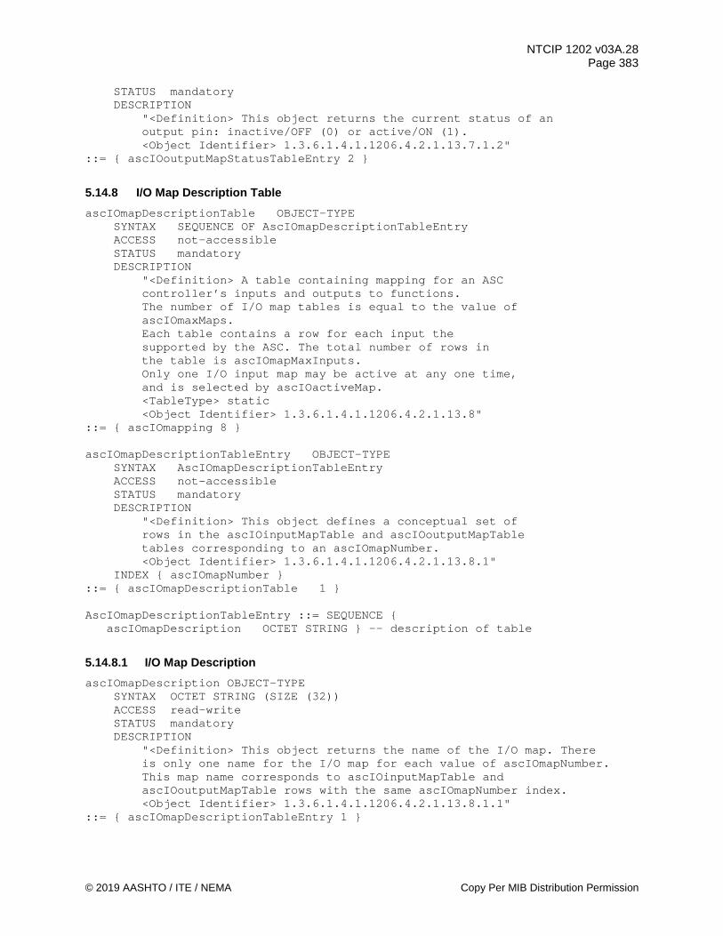
NTCIP 1202 v03A.28 Page 383
© 2019 AASHTO / ITE / NEMA Copy Per MIB Distribution Permission
STATUS mandatory DESCRIPTION "<Definition> This object returns the current status of an output pin: inactive/OFF (0) or active/ON (1). <Object Identifier> 1.3.6.1.4.1.1206.4.2.1.13.7.1.2" ::= { ascIOoutputMapStatusTableEntry 2 }
5.14.8 I/O Map Description Table ascIOmapDescriptionTable OBJECT-TYPE SYNTAX SEQUENCE OF AscIOmapDescriptionTableEntry ACCESS not-accessible STATUS mandatory DESCRIPTION "<Definition> A table containing mapping for an ASC controller’s inputs and outputs to functions. The number of I/O map tables is equal to the value of ascIOmaxMaps. Each table contains a row for each input the supported by the ASC. The total number of rows in the table is ascIOmapMaxInputs. Only one I/O input map may be active at any one time, and is selected by ascIOactiveMap. <TableType> static <Object Identifier> 1.3.6.1.4.1.1206.4.2.1.13.8" ::= { ascIOmapping 8 } ascIOmapDescriptionTableEntry OBJECT-TYPE SYNTAX AscIOmapDescriptionTableEntry ACCESS not-accessible STATUS mandatory DESCRIPTION "<Definition> This object defines a conceptual set of rows in the ascIOinputMapTable and ascIOoutputMapTable tables corresponding to an ascIOmapNumber. <Object Identifier> 1.3.6.1.4.1.1206.4.2.1.13.8.1" INDEX { ascIOmapNumber } ::= { ascIOmapDescriptionTable 1 } AscIOmapDescriptionTableEntry ::= SEQUENCE { ascIOmapDescription OCTET STRING } -- description of table
5.14.8.1 I/O Map Description ascIOmapDescription OBJECT-TYPE SYNTAX OCTET STRING (SIZE (32)) ACCESS read-write STATUS mandatory DESCRIPTION "<Definition> This object returns the name of the I/O map. There is only one name for the I/O map for each value of ascIOmapNumber. This map name corresponds to ascIOinputMapTable and ascIOoutputMapTable rows with the same ascIOmapNumber index. <Object Identifier> 1.3.6.1.4.1.1206.4.2.1.13.8.1.1" ::= { ascIOmapDescriptionTableEntry 1 }
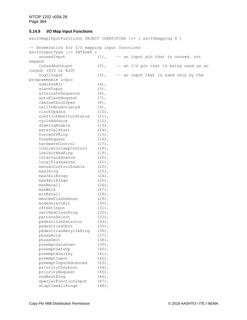
NTCIP 1202 v03A.28 Page 384
Copy Per MIB Distribution Permission © 2019 AASHTO / ITE / NEMA
5.14.9 I/O Map Input Functions ascIOmapInputFunctions OBJECT IDENTIFIER ::= { ascIOmapping 9 } -- Enumeration for I/O mapping input functions AscIOinputType ::= INTEGER { unusedInput (1), -- an input pin that is unused, not mapped ioUsedAsOutput (2), -- an I/O pin that is being used as an output (SIU or BIU) logicInput (3), -- an input that is used only by the programmable logic addressBit (4), alarmInput (5), alternateSequence (6), autoFlashRequest (7), cabinetDoorOpen (8), callToNonActuated (9), clockUpdate (10), conflictMonitorStatus (11), cycleAdvance (12), dimmingEnable (13), externalStart (14), forceOffRing (15), freeRequest (16), hardwareControl (17), indicatorLampControl (18), inhibitMaxRing (19), intervalAdvance (20), localFlashSense (21), manualControlEnable (22), max2Ring (23), max3AllRings (24), max4AllRings (25), maxRecall (26), maxWalk (27), minRecall (28), mmuCmuFlashSense (29), modeSelectBit (30), offsetInput (31), omitRedClearRing (32), patternSelect (33), pedestrianDetector (34), pedestrianOmit (35), pedestrianRecycleRing (36), phaseHold (37), phaseOmit (38), preemptGateDown (39), preemptGateUp (40), preemptHealthy (41), preemptInput (42), preemptInputAdvanced (43), priorityCheckout (44), priorityRequest (45), redRestRing (46), specialFunctionInput (47), stopTimeAllRings (48),
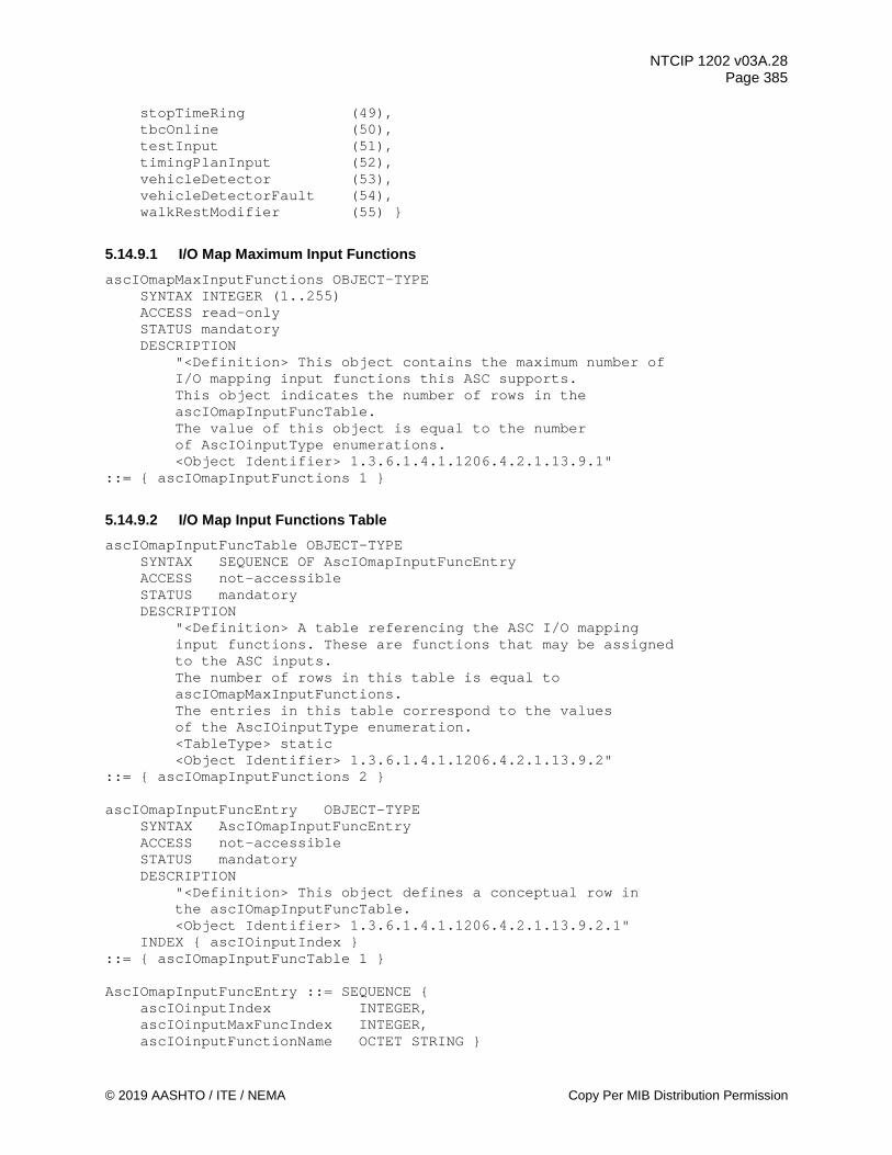
NTCIP 1202 v03A.28 Page 385
© 2019 AASHTO / ITE / NEMA Copy Per MIB Distribution Permission
stopTimeRing (49), tbcOnline (50), testInput (51), timingPlanInput (52), vehicleDetector (53), vehicleDetectorFault (54),
walkRestModifier (55) }
5.14.9.1 I/O Map Maximum Input Functions ascIOmapMaxInputFunctions OBJECT-TYPE SYNTAX INTEGER (1..255) ACCESS read-only STATUS mandatory DESCRIPTION "<Definition> This object contains the maximum number of I/O mapping input functions this ASC supports. This object indicates the number of rows in the ascIOmapInputFuncTable. The value of this object is equal to the number of AscIOinputType enumerations. <Object Identifier> 1.3.6.1.4.1.1206.4.2.1.13.9.1" ::= { ascIOmapInputFunctions 1 }
5.14.9.2 I/O Map Input Functions Table ascIOmapInputFuncTable OBJECT-TYPE SYNTAX SEQUENCE OF AscIOmapInputFuncEntry ACCESS not-accessible STATUS mandatory DESCRIPTION "<Definition> A table referencing the ASC I/O mapping input functions. These are functions that may be assigned to the ASC inputs. The number of rows in this table is equal to ascIOmapMaxInputFunctions. The entries in this table correspond to the values of the AscIOinputType enumeration. <TableType> static <Object Identifier> 1.3.6.1.4.1.1206.4.2.1.13.9.2" ::= { ascIOmapInputFunctions 2 } ascIOmapInputFuncEntry OBJECT-TYPE SYNTAX AscIOmapInputFuncEntry ACCESS not-accessible STATUS mandatory DESCRIPTION "<Definition> This object defines a conceptual row in the ascIOmapInputFuncTable. <Object Identifier> 1.3.6.1.4.1.1206.4.2.1.13.9.2.1" INDEX { ascIOinputIndex } ::= { ascIOmapInputFuncTable 1 } AscIOmapInputFuncEntry ::= SEQUENCE { ascIOinputIndex INTEGER, ascIOinputMaxFuncIndex INTEGER, ascIOinputFunctionName OCTET STRING }

NTCIP 1202 v03A.28 Page 386
Copy Per MIB Distribution Permission © 2019 AASHTO / ITE / NEMA
5.14.9.2.1 I/O Map Input Functions Table Index ascIOinputIndex OBJECT-TYPE SYNTAX INTEGER (1..255) ACCESS read-only STATUS mandatory DESCRIPTION "<Definition> Indicates the row number of the entry in the ascIOmapInputFuncTable. The value of this object shall not exceed the ascIOmapMaxInputFunctions value. These indexes correspond to the values of the AscIOinputType enumeration. <Object Identifier> 1.3.6.1.4.1.1206.4.2.1.13.9.2.1.1" ::= { ascIOmapInputFuncEntry 1 }
5.14.9.2.2 I/O Map Input Function Maximum Index ascIOinputMaxFuncIndex OBJECT-TYPE SYNTAX INTEGER (1..255) ACCESS read-only STATUS mandatory DESCRIPTION "<Definition> Some input functions support an array of inputs, this object indicates the maximum array index for this input function. <Object Identifier> 1.3.6.1.4.1.1206.4.2.1.13.9.2.1.2" ::= { ascIOmapInputFuncEntry 2 }
5.14.9.2.3 I/O Map Input Function Name ascIOinputFunctionName OBJECT-TYPE SYNTAX OCTET STRING (SIZE (32)) ACCESS read-only STATUS mandatory DESCRIPTION "<Definition> This object contains an ASCII string describing the input function. <Object Identifier> 1.3.6.1.4.1.1206.4.2.1.13.9.2.1.3" ::= { ascIOmapInputFuncEntry 3 }
5.14.10 I/O Map Output Functions ascIOmapOutputFunctions OBJECT IDENTIFIER ::= { ascIOmapping 10 } -- Enumeration for I/O mapping output functions AscIOoutputType ::= INTEGER { unusedOutput (1), -- an output pin that is unused, not mapped ioUsedAsInput (2), -- an I/O pin that is being used as an input (SIU or BIU) logicOutput (3), -- an output function from the programmable logic advWarnGrn (4),
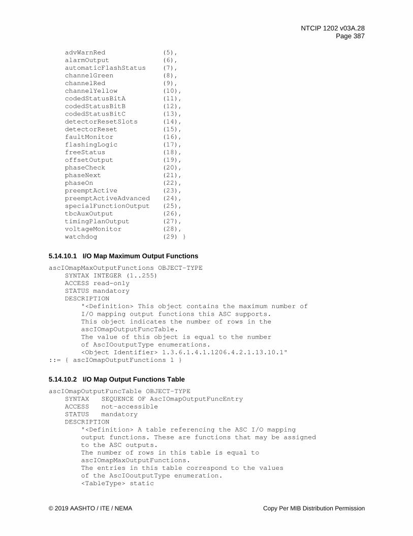
NTCIP 1202 v03A.28 Page 387
© 2019 AASHTO / ITE / NEMA Copy Per MIB Distribution Permission
advWarnRed (5), alarmOutput (6), automaticFlashStatus (7), channelGreen (8), channelRed (9), channelYellow (10), codedStatusBitA (11), codedStatusBitB (12), codedStatusBitC (13), detectorResetSlots (14), detectorReset (15), faultMonitor (16), flashingLogic (17), freeStatus (18), offsetOutput (19), phaseCheck (20), phaseNext (21), phaseOn (22), preemptActive (23), preemptActiveAdvanced (24), specialFunctionOutput (25), tbcAuxOutput (26), timingPlanOutput (27), voltageMonitor (28), watchdog (29) }
5.14.10.1 I/O Map Maximum Output Functions ascIOmapMaxOutputFunctions OBJECT-TYPE SYNTAX INTEGER (1..255) ACCESS read-only STATUS mandatory DESCRIPTION "<Definition> This object contains the maximum number of I/O mapping output functions this ASC supports. This object indicates the number of rows in the ascIOmapOutputFuncTable. The value of this object is equal to the number of AscIOoutputType enumerations. <Object Identifier> 1.3.6.1.4.1.1206.4.2.1.13.10.1" ::= { ascIOmapOutputFunctions 1 }
5.14.10.2 I/O Map Output Functions Table ascIOmapOutputFuncTable OBJECT-TYPE SYNTAX SEQUENCE OF AscIOmapOutputFuncEntry ACCESS not-accessible STATUS mandatory DESCRIPTION "<Definition> A table referencing the ASC I/O mapping output functions. These are functions that may be assigned to the ASC outputs. The number of rows in this table is equal to ascIOmapMaxOutputFunctions. The entries in this table correspond to the values of the AscIOoutputType enumeration. <TableType> static

NTCIP 1202 v03A.28 Page 388
Copy Per MIB Distribution Permission © 2019 AASHTO / ITE / NEMA
<Object Identifier> 1.3.6.1.4.1.1206.4.2.1.13.10.2" ::= { ascIOmapOutputFunctions 2 } ascIOmapOutputFuncEntry OBJECT-TYPE SYNTAX AscIOmapOutputFuncEntry ACCESS not-accessible STATUS mandatory DESCRIPTION "<Definition> This object defines a conceptual row in the ascIOmapOutputFuncTable. <Object Identifier> 1.3.6.1.4.1.1206.4.2.1.13.10.2.1" INDEX { ascIOoutputIndex } ::= { ascIOmapOutputFuncTable 1 } AscIOmapOutputFuncEntry ::= SEQUENCE { ascIOoutputIndex INTEGER, ascIOoutputMaxFuncIndex INTEGER, ascIOoutputFunctionName OCTET STRING }
5.14.10.2.1 I/O Map Output Functions Table Index ascIOoutputIndex OBJECT-TYPE SYNTAX INTEGER (1..255) ACCESS read-only STATUS mandatory DESCRIPTION "<Definition> Indicates the row number of the entry in the ascIOmapOutputFuncTable. The value of this object shall not exceed the ascIOmapMaxOutputFunctions value. These indexes correspond to the values of the AscIOoutputType enumeration. <Object Identifier> 1.3.6.1.4.1.1206.4.2.1.13.10.2.1.1" ::= { ascIOmapOutputFuncEntry 1 }
5.14.10.2.2 I/O Map Output Function Maximum Index ascIOoutputMaxFuncIndex OBJECT-TYPE SYNTAX INTEGER (1..255) ACCESS read-only STATUS mandatory DESCRIPTION "<Definition> Some output functions support an array of outputs, this object indicates the maximum array index for this output function. <Object Identifier> 1.3.6.1.4.1.1206.4.2.1.13.10.2.1.2" ::= { ascIOmapOutputFuncEntry 2 }
5.14.10.2.3 I/O Map Output Function Name ascIOoutputFunctionName OBJECT-TYPE SYNTAX OCTET STRING (SIZE (32)) ACCESS read-only STATUS mandatory DESCRIPTION "<Definition> This object contains an ASCII string describing

NTCIP 1202 v03A.28 Page 389
© 2019 AASHTO / ITE / NEMA Copy Per MIB Distribution Permission
the output function. <<Object Identifier> 1.3.6.1.4.1.1206.4.2.1.13.10.2.1.3" ::= { ascIOmapOutputFuncEntry 3 }
5.14.11 I/O Map FIO Pins ascIOmapFIO OBJECT IDENTIFIER ::= { ascIOmapping 11 }
5.14.11.1 I/O Map FIO Input Pins AscIOmapFIOinputs ::= INTEGER { -- Enumeration for 2070-2A FIO (170) inputs pinC1-39 (1), -- Detector 2 pinC1-40 (2), -- Detector 16 pinC1-41 (3), -- Detector 8 pinC1-42 (4), -- Detector 22 pinC1-43 (5), -- Detector 3 pinC1-44 (6), -- Detector 17 pinC1-45 (7), -- Detector 9 pinC1-46 (8), -- Detector 23 pinC1-47 (9), -- Detector 6 pinC1-48 (10), -- Detector 20 pinC1-49 (11), -- Detector 12 pinC1-50 (12), -- Detector 26 pinC1-51 (13), -- RR1 Preempt pinC1-52 (14), -- RR2 Preempt pinC1-53 (15), -- Manual Control pinC1-54 (16), -- Spare pinC1-55 (17), -- Detector 15 pinC1-56 (18), -- Detector 1 pinC1-57 (19), -- Detector 21 pinC1-58 (20), -- Detector 7 pinC1-59 (21), -- Detector 27 pinC1-60 (22), -- Detector 13 pinC1-61 (23), -- Detector 28 pinC1-62 (24), -- Detector 14 pinC1-63 (25), -- Detector 4 pinC1-64 (26), -- Detector 18 pinC1-65 (27), -- Detector 10 pinC1-66 (28), -- Detector 24 pinC1-67 (29), -- Ped Detector 1 pinC1-68 (30), -- Ped Detector 3 pinC1-69 (31), -- Ped Detector 2 pinC1-70 (32), -- Ped Detector 4 pinC1-71 (33), -- EVA Preempt pinC1-72 (34), -- EVB Preempt pinC1-73 (35), -- EVC Preempt pinC1-74 (36), -- EVD Preempt pinC1-75 (37), -- Spare pinC1-76 (38), -- Detector 5 pinC1-77 (39), -- Detector 19 pinC1-78 (40), -- Detector 11 pinC1-79 (41), -- Detector 25 pinC1-80 (42), -- Interval Advance pinC1-81 (43), -- Flash Sense pinC1-82 (44), -- Stop Time pinC11-10 (45), -- C11 inputs all spare

NTCIP 1202 v03A.28 Page 390
Copy Per MIB Distribution Permission © 2019 AASHTO / ITE / NEMA
pinC11-11 (46), pinC11-12 (47), pinC11-13 (48), pinC11-15 (49), pinC11-16 (50), pinC11-17 (51), pinC11-18 (52), pinC11-19 (53), pinC11-20 (54), pinC11-21 (55), pinC11-22 (56), pinC11-23 (57), pinC11-24 (58), pinC11-25 (69), pinC11-26 (60), pinC11-27 (61), pinC11-28 (62), pinC11-29 (63), pinC11-30 (64) }
5.14.11.2 I/O Map FIO Output Pins AscIOmapFIOoutputs ::= INTEGER { -- Enumeration for 2070-2A FIO (170) outputs pinC1-2 (1), -- Ped 4 red pinC1-3 (2), -- Ped 4 green pinC1-4 (3), -- Phase 4 red pinC1-5 (4), -- Phase 4 yellow pinC1-6 (5), -- Phase 4 green pinC1-7 (6), -- Phase 3 red pinC1-8 (7), -- Phase 3 yellow pinC1-9 (8), -- Phase 3 green pinC1-10 (9), -- Ped 2 red pinC1-11 (10), -- Ped 2 green pinC1-12 (11), -- Phase 2 red pinC1-13 (12), -- Phase 2 yellow pinC1-15 (13), -- Phase 2 green pinC1-16 (14), -- Phase 1 red pinC1-17 (15), -- Phase 1 yellow pinC1-18 (16), -- Phase 1 green pinC1-19 (17), -- Ped 8 red pinC1-20 (18), -- Ped 8 green pinC1-21 (19), -- Phase 8 red pinC1-22 (20), -- Phase 8 yellow pinC1-23 (21), -- Phase 8 green pinC1-24 (22), -- Phase 7 red pinC1-25 (23), -- Phase 7 yellow pinC1-26 (24), -- Phase 7 green pinC1-27 (25), -- Ped 6 red pinC1-28 (26), -- Ped 6 green pinC1-29 (27), -- Phase 6 red pinC1-30 (28), -- Phase 6 yellow pinC1-31 (29), -- Phase 6 green pinC1-32 (30), -- Phase 5 red pinC1-33 (31), -- Phase 5 yellow pinC1-34 (32), -- Phase 5 green pinC1-35 (33), -- Ped 2 yellow

NTCIP 1202 v03A.28 Page 391
© 2019 AASHTO / ITE / NEMA Copy Per MIB Distribution Permission
pinC1-36 (34), -- Ped 6 yellow pinC1-37 (35), -- Ped 4 yellow pinC1-38 (36), -- Ped 8 yellow pinC1-83 (37), -- Spare pinC1-84 (38), -- Spare pinC1-85 (39), -- Overlap D red pinC1-86 (40), -- Overlap D yellow pinC1-87 (41), -- Overlap D green pinC1-88 (42), -- Overlap C red pinC1-89 (43), -- Overlap C yellow pinC1-90 (44), -- Overlap C green pinC1-91 (45), -- Spare pinC1-93 (46), -- Spare pinC1-94 (47), -- Overlap B red pinC1-95 (48), -- Overlap B yellow pinC1-96 (49), -- Overlap B green pinC1-97 (50), -- Overlap A red pinC1-98 (51), -- Overlap A yellow pinC1-99 (52), -- Overlap A green pinC1-100 (53), -- Spare pinC1-101 (54), -- Flash status pinC1-102 (55), -- Detector reset pinC1-103 (56), -- Watchdog pinC11-1 (57), -- all C11 outputs are spare pinC11-2 (58), pinC11-3 (59), pinC11-4 (60), pinC11-5 (61), pinC11-6 (62), pinC11-7 (63), pinC11-8 (64) }
5.14.12 I/O Map TS1 Pins ascIOmapTS1 OBJECT IDENTIFIER ::= { ascIOmapping 12 }
5.14.12.1 I/O Map TS1 Input Pins AscIOmapTS1inputs ::= INTEGER { -- Enumeration for type 2070-8 NEMA TS1 inputs pinA-f (1), -- Vehicle Detector 1 pinA-g (2), -- Ped Detector 1 pinA-h (3), -- Hold 1 pinA-i (4), -- Force Off Ring 1 pinA-j (5), -- Min Recall pinA-k (6), -- Manual Control pinA-m (7), -- CNA 1 pinA-n (8), -- Test A pinA-q (9), -- Mode Bit A pinA-v (10), -- Ped Omit 2 pinA-w (11), -- Omit Red Ring 1 pinA-x (12), -- Red Rest Ring 1 pinA-y (13), -- Mode Bit B pinA-z (14), -- CNA 2 pinA-K (15), -- Vehicle Detector 2 pinA-L (16), -- Ped Detector 2 pinA-M (17), -- Hold 2
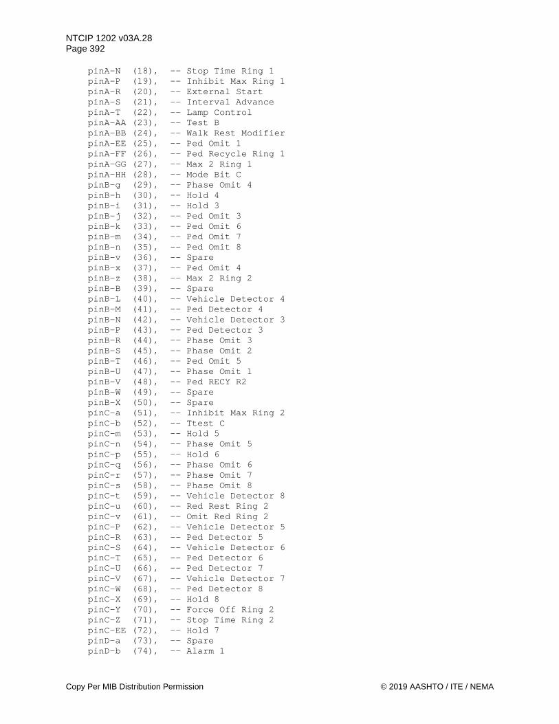
NTCIP 1202 v03A.28 Page 392
Copy Per MIB Distribution Permission © 2019 AASHTO / ITE / NEMA
pinA-N (18), -- Stop Time Ring 1 pinA-P (19), -- Inhibit Max Ring 1 pinA-R (20), -- External Start pinA-S (21), -- Interval Advance pinA-T (22), -- Lamp Control pinA-AA (23), -- Test B pinA-BB (24), -- Walk Rest Modifier pinA-EE (25), -- Ped Omit 1 pinA-FF (26), -- Ped Recycle Ring 1 pinA-GG (27), -- Max 2 Ring 1 pinA-HH (28), -- Mode Bit C pinB-g (29), -- Phase Omit 4 pinB-h (30), -- Hold 4 pinB-i (31), -- Hold 3 pinB-j (32), -- Ped Omit 3 pinB-k (33), -- Ped Omit 6 pinB-m (34), -- Ped Omit 7 pinB-n (35), -- Ped Omit 8 pinB-v (36), -- Spare pinB-x (37), -- Ped Omit 4 pinB-z (38), -- Max 2 Ring 2 pinB-B (39), -- Spare pinB-L (40), -- Vehicle Detector 4 pinB-M (41), -- Ped Detector 4 pinB-N (42), -- Vehicle Detector 3 pinB-P (43), -- Ped Detector 3 pinB-R (44), -- Phase Omit 3 pinB-S (45), -- Phase Omit 2 pinB-T (46), -- Ped Omit 5 pinB-U (47), -- Phase Omit 1 pinB-V (48), -- Ped RECY R2 pinB-W (49), -- Spare pinB-X (50), -- Spare pinC-a (51), -- Inhibit Max Ring 2 pinC-b (52), -- Ttest C pinC-m (53), -- Hold 5 pinC-n (54), -- Phase Omit 5 pinC-p (55), -- Hold 6 pinC-q (56), -- Phase Omit 6 pinC-r (57), -- Phase Omit 7 pinC-s (58), -- Phase Omit 8 pinC-t (59), -- Vehicle Detector 8 pinC-u (60), -- Red Rest Ring 2 pinC-v (61), -- Omit Red Ring 2 pinC-P (62), -- Vehicle Detector 5 pinC-R (63), -- Ped Detector 5 pinC-S (64), -- Vehicle Detector 6 pinC-T (65), -- Ped Detector 6 pinC-U (66), -- Ped Detector 7 pinC-V (67), -- Vehicle Detector 7 pinC-W (68), -- Ped Detector 8 pinC-X (69), -- Hold 8 pinC-Y (70), -- Force Off Ring 2 pinC-Z (71), -- Stop Time Ring 2 pinC-EE (72), -- Hold 7 pinD-a (73), -- Spare pinD-b (74), -- Alarm 1

NTCIP 1202 v03A.28 Page 393
© 2019 AASHTO / ITE / NEMA Copy Per MIB Distribution Permission
pinD-c (75), -- Alarm 2 pinD-d (76), -- Alarm 3 pinD-e (77), -- Alarm 4 pinD-f (78), -- Alarm 5 pinD-g (79), -- Flash In pinD-h (80), -- Conflict Monitor Status pinD-i (81), -- Door Open pinD-j (82), -- Special Function 1 pinD-k (83), -- Special Function 2 pinD-m (84), -- Special Function 3 pinD-n (85), -- Special Function 4 pinD-p (86), -- Special Function 5 pinD-q (87), -- Special Function 6 pinD-r (88), -- Special Function 7 pinD-s (89), -- Special Function 8 pinD-t (90), -- Preempt 1 pinD-u (91), -- Preempt 2 pinD-v (92), -- Preempt 3 pinD-w (93), -- Preempt 4 pinD-x (94), -- Preempt 5 pinD-y (95), -- Preempt 6 pinD-A (96), -- Vehicle Detector 9 pinD-B (97), -- Vehicle Detector 10 pinD-C (98), -- Vehicle Detector 11 pinD-D (99), -- Vehicle Detector 12 pinD-E (100), -- Vehicle Detector 13 pinD-F (101), -- Vehicle Detector 14 pinD-G (102), -- Vehicle Detector 15 pinD-H (103), -- Vehicle Detector 16 pinD-J (104), -- Vehicle Detector 17 pinD-K (105), -- Vehicle Detector 18 pinD-L (106), -- Vehicle Detector 19 pinD-M (107), -- Vehicle Detector 20 pinD-N (108), -- Vehicle Detector 21 pinD-P (109), -- Vehicle Detector 22 pinD-R (110), -- Vehicle Detector 23 pinD-S (111), -- Vehicle Detector 24 pinD-T (112), -- Clock Update pinD-U (113), -- Hardware Control pinD-V (114), -- Cycle Advance pinD-W (115), -- Max 3 Select pinD-X (116), -- Max 4 Select pinD-Y (117), -- Free pinD-Z (118), -- Spare pinD-KK (119), -- Spare pinD-MM (120) } -- Spare
5.14.12.2 I/O Map TS1 Output Pins AscIOmapTS1outputs ::= INTEGER { -- Enumeration for 2070-8 NEMA TS1 outputs pinA-a (1), -- Ped 1 Yellow pinA-b (2), -- Phase 2 Yellow pinA-c (3), -- Phase 2 Green pinA-d (4), -- Phase Check 2 pinA-e (5), -- Phase On 2 pinA-r (6), -- Status B Ring 1

NTCIP 1202 v03A.28 Page 394
Copy Per MIB Distribution Permission © 2019 AASHTO / ITE / NEMA
pinA-s (7), -- Phase 1 Green pinA-t (8), -- Ped 1 Green pinA-u (9), -- Phase Check 1 pinA-A (10), -- Fault Monitor pinA-C (11), -- Voltage Monitor pinA-D (12), -- Phase 1 Red pinA-E (13), -- Ped 1 Red pinA-F (14), -- Phase 2 Red pinA-G (15), -- Ped 2 Red pinA-H (16), -- Ped 2 Yellow pinA-J (17), -- Ped 2 Green pinA-X (18), -- Flashing Logic pinA-Y (19), -- Status C Ring 1 pinA-Z (20), -- Phase 1 Yellow pinA-CC (21), -- Status A Ring 1 pinA-DD (22), -- Phase ON 1 pinB-a (23), -- Ped 3 Red pinB-b (24), -- Phase 4 Green pinB-c (25), -- Phase 4 Yellow pinB-d (26), -- Ped 4 Green pinB-e (27), -- Phase On 4 pinB-f (28), -- Phase Next 4 pinB-p (29), -- Overlap A Yellow pinB-q (30), -- Overlap A Red pinB-r (31), -- Phase Check 3 pinB-s (32), -- Phase On 3 pinB-t (33), -- Phase Next 3 pinB-u (34), -- Overlap D Red pinB-w (35), -- Overlap D Green pinB-A (36), -- Phase Next 1 pinB-C (37), -- Phase Next 2 pinB-D (38), -- Phase 3 Green pinB-E (39), -- Phase 3 Yellow pinB-F (40), -- Phase 3 Red pinB-G (41), -- Phase 4 Red pinB-H (42), -- Ped 4 Yellow pinB-J (43), -- Ped 4 Red pinB-K (44), -- Phase Check 4 pinB-Y (45), -- Ped 3 Green pinB-Z (46), -- Ped 3 Yellow pinB-AA (47), -- Overlap A Green pinB-BB (48), -- Overlap B Yellow pinB-CC (49), -- Overlap B Red pinB-DD (50), -- Overlap C Red pinB-EE (51), -- Overlap D Yellow pinB-FF (52), -- Overlap C Green pinB-GG (53), -- Overlap B Green pinB-HH (54), -- Overlap C Yellow pinC-c (55), -- Status C Ring 2 pinC-d (56), -- Ped 8 Green pinC-e (57), -- Phase 8 Yellow pinC-f (58), -- Phase 7 Green pinC-g (59), -- Phase 6 Green pinC-h (60), -- Phase 6 Yellow pinC-i (61), -- Phase 5 Green pinC-j (62), -- Ped 5 Green pinC-k (63), -- Phase Check 5

NTCIP 1202 v03A.28 Page 395
© 2019 AASHTO / ITE / NEMA Copy Per MIB Distribution Permission
pinC-w (64), -- Ped 8 Yellow pinC-x (65), -- Phase 8 Green pinC-y (66), -- Ped 7 Red pinC-z (67), -- Ped 6 Red pinC-A (68), -- Status A Ring 2 pinC-B (69), -- Status B Ring 2 pinC-C (70), -- Ped 8 Red pinC-D (71), -- Phase 8 Red pinC-E (72), -- Phase 7 Yellow pinC-F (73), -- Phase 7 Red pinC-G (74), -- Phase 6 Red pinC-H (75), -- Phase 5 Red pinC-J (76), -- Phase 5 Yellow pinC-K (77), -- Ped 5 Yellow pinC-L (78), -- Ped 5 Red pinC-M (79), -- Phase Next 5 pinC-N (80), -- Phase On 5 pinC-AA (81), -- Ped 6 Yellow pinC-BB (82), -- Phase Check 6 pinC-CC (83), -- Phase ON 6 pinC-DD (84), -- Phase Next 6 pinC-FF (85), -- Phase Check 8 pinC-GG (86), -- Phase On 8 pinC-HH (87), -- Phase Next 8 pinC-JJ (88), -- Ped 7 Green pinC-KK (89), -- Ped 7 Yellow pinC-LL (90), -- Ped 6 Green pinC-MM (91), -- Phase Check 7 pinC-NN (92), -- Phase On 7 pinC-PP (93), -- Phase Next 7 pinD-z (94), -- Alarm 1 pinD-AA (95), -- Alarm 2 pinD-BB (96), -- Special Function 1 pinD-CC (97), -- Special Function 2 pinD-DD (98), -- Special Function 3 pinD-EE (99), -- Special Function 4 pinD-FF (100), -- Special Function 5 pinD-GG (101), -- Special Function 6 pinD-HH (102), -- Special Function 7 pinD-JJ (103), -- Special Function 8 pinD-LL (104) } -- Detector Reset
5.14.13 I/O Map TS2 BIU Pins ascIOmapBIU OBJECT IDENTIFIER ::= { ascIOmapping 13 }
5.14.13.1 I/O Map TS2 BIU Input Pins AscIOmapBIUinputs ::= INTEGER { -- Enumeration for NEMA TS2 BIU inputs (for each BIU) biuInputIO1 (1), biuInputIO2 (2), biuInputIO3 (3), biuInputIO4 (4), biuInputIO5 (5), biuInputIO6 (6), biuInputIO7 (7),

NTCIP 1202 v03A.28 Page 396
Copy Per MIB Distribution Permission © 2019 AASHTO / ITE / NEMA
biuInputIO8 (8), biuInputIO9 (9), biuInputIO10 (10), biuInputIO11 (11), biuInputIO12 (12), biuInputIO13 (13), biuInputIO14 (14), biuInputIO15 (15), biuInputIO16 (16), biuInputIO17 (17), biuInputIO18 (18), biuInputIO19 (19), biuInputIO20 (20), biuInputIO21 (21), biuInputIO22 (22), biuInputIO23 (23), biuInputIO24 (24), biuInputIN1 (25), biuInputIN2 (26), biuInputIN3 (27), biuInputIN4 (28), biuInputIN5 (29), biuInputIN6 (30), biuInputIN7 (31), biuInputIN8 (32), biuInputOPT1 (33), biuInputOPT2 (34), biuInputOPT3 (35), biuInputOPT4 (36) }
5.14.13.2 I/O Map TS2 BIU Output Pins AscIOmapBIUoutputs ::= INTEGER { -- Enumeration for NEMA TS2 BIU outputs (for each BIU) biuOutputO1 (1), biuOutputO2 (2), biuOutputO3 (3), biuOutputO4 (4), biuOutputO5 (5), biuOutputO6 (6), biuOutputO7 (7), biuOutputO8 (8), biuOutputO9 (9), biuOutputO10 (10), biuOutputO11 (11), biuOutputO12 (12), biuOutputO13 (13), biuOutputO14 (14), biuOutputO15 (15), biuOutputIO1 (16), biuOutputIO2 (17), biuOutputIO3 (18), biuOutputIO4 (19), biuOutputIO5 (20), biuOutputIO6 (21), biuOutputIO7 (22), biuOutputIO8 (23),
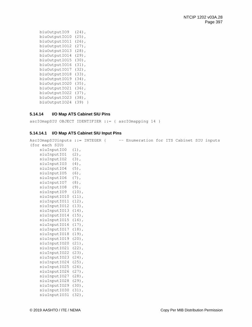
NTCIP 1202 v03A.28 Page 397
© 2019 AASHTO / ITE / NEMA Copy Per MIB Distribution Permission
biuOutputIO9 (24), biuOutputIO10 (25), biuOutputIO11 (26), biuOutputIO12 (27), biuOutputIO13 (28), biuOutputIO14 (29), biuOutputIO15 (30), biuOutputIO16 (31), biuOutputIO17 (32), biuOutputIO18 (33), biuOutputIO19 (34), biuOutputIO20 (35), biuOutputIO21 (36), biuOutputIO22 (37), biuOutputIO23 (38), biuOutputIO24 (39) }
5.14.14 I/O Map ATS Cabinet SIU Pins ascIOmapSIU OBJECT IDENTIFIER ::= { ascIOmapping 14 }
5.14.14.1 I/O Map ATS Cabinet SIU Input Pins AscIOmapSIUinputs ::= INTEGER { -- Enumeration for ITS Cabinet SIU inputs (for each SIU) siuInputIO0 (1), siuInputIO1 (2), siuInputIO2 (3), siuInputIO3 (4), siuInputIO4 (5), siuInputIO5 (6), siuInputIO6 (7), siuInputIO7 (8), siuInputIO8 (9), siuInputIO9 (10), siuInputIO10 (11), siuInputIO11 (12), siuInputIO12 (13), siuInputIO13 (14), siuInputIO14 (15), siuInputIO15 (16), siuInputIO16 (17), siuInputIO17 (18), siuInputIO18 (19), siuInputIO19 (20), siuInputIO20 (21), siuInputIO21 (22), siuInputIO22 (23), siuInputIO23 (24), siuInputIO24 (25), siuInputIO25 (26), siuInputIO26 (27), siuInputIO27 (28), siuInputIO28 (29), siuInputIO29 (30), siuInputIO30 (31), siuInputIO31 (32),
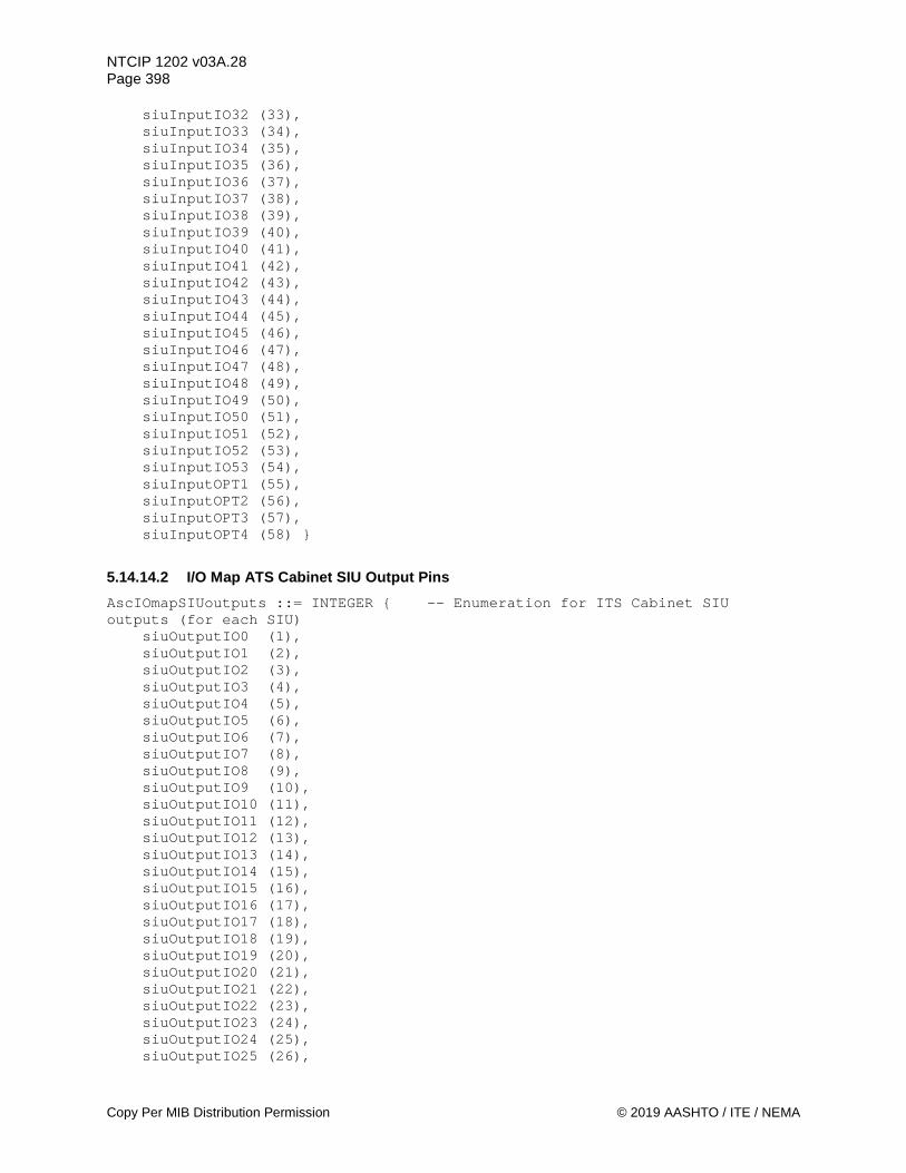
NTCIP 1202 v03A.28 Page 398
Copy Per MIB Distribution Permission © 2019 AASHTO / ITE / NEMA
siuInputIO32 (33), siuInputIO33 (34), siuInputIO34 (35), siuInputIO35 (36), siuInputIO36 (37), siuInputIO37 (38), siuInputIO38 (39), siuInputIO39 (40), siuInputIO40 (41), siuInputIO41 (42), siuInputIO42 (43), siuInputIO43 (44), siuInputIO44 (45), siuInputIO45 (46), siuInputIO46 (47), siuInputIO47 (48), siuInputIO48 (49), siuInputIO49 (50), siuInputIO50 (51), siuInputIO51 (52), siuInputIO52 (53), siuInputIO53 (54), siuInputOPT1 (55), siuInputOPT2 (56), siuInputOPT3 (57), siuInputOPT4 (58) }
5.14.14.2 I/O Map ATS Cabinet SIU Output Pins AscIOmapSIUoutputs ::= INTEGER { -- Enumeration for ITS Cabinet SIU outputs (for each SIU) siuOutputIO0 (1), siuOutputIO1 (2), siuOutputIO2 (3), siuOutputIO3 (4), siuOutputIO4 (5), siuOutputIO5 (6), siuOutputIO6 (7), siuOutputIO7 (8), siuOutputIO8 (9), siuOutputIO9 (10), siuOutputIO10 (11), siuOutputIO11 (12), siuOutputIO12 (13), siuOutputIO13 (14), siuOutputIO14 (15), siuOutputIO15 (16), siuOutputIO16 (17), siuOutputIO17 (18), siuOutputIO18 (19), siuOutputIO19 (20), siuOutputIO20 (21), siuOutputIO21 (22), siuOutputIO22 (23), siuOutputIO23 (24), siuOutputIO24 (25), siuOutputIO25 (26),

NTCIP 1202 v03A.28 Page 399
© 2019 AASHTO / ITE / NEMA Copy Per MIB Distribution Permission
siuOutputIO26 (27), siuOutputIO27 (28), siuOutputIO28 (29), siuOutputIO29 (30), siuOutputIO30 (31), siuOutputIO31 (32), siuOutputIO32 (33), siuOutputIO33 (34), siuOutputIO34 (35), siuOutputIO35 (36), siuOutputIO36 (37), siuOutputIO37 (38), siuOutputIO38 (39), siuOutputIO39 (40), siuOutputIO40 (41), siuOutputIO41 (42), siuOutputIO42 (43), siuOutputIO43 (44), siuOutputIO44 (45), siuOutputIO45 (46), siuOutputIO46 (47), siuOutputIO47 (48), siuOutputIO48 (49), siuOutputIO49 (50), siuOutputIO50 (51), siuOutputIO51 (52), siuOutputIO52 (53), siuOutputIO53 (54) }
5.14.15 I/O Map Auxiliary Device Pins ascIOmapAUX OBJECT IDENTIFIER ::= { ascIOmapping 15 }
5.14.15.1 I/O Map Auxiliary Device Input Pins AscIOmapAUXinputs ::= INTEGER { -- Enumeration for AUX inputs auxInputFPSwitch (1), -- front panel AUX switch auxInputIO0 (2), auxInputIO1 (3), auxInputIO2 (4), auxInputIO3 (5), auxInputIO4 (6), auxInputIO5 (7), auxInputIO6 (8),
auxInputIO7 (9) }
5.14.15.2 I/O Map Auxiliary Device Outputs AscIOmapAUXoutputs ::= INTEGER { -- Enumeration for AUX outputs auxOutputIO0 (1), auxOutputIO1 (2), auxOutputIO2 (3), auxOutputIO3 (4), auxOutputIO4 (5), auxOutputIO5 (6),

NTCIP 1202 v03A.28 Page 400
Copy Per MIB Distribution Permission © 2019 AASHTO / ITE / NEMA
auxOutputIO6 (7), auxOutputIO7 (8) }
5.15 SIU Port 1 Parameters siuport1 OBJECT IDENTIFIER ::= { asc 14 } -- This object is an identifier used to group all objects for -- support of ITS Cabinet V1 Section 4.7.14.7.1 SIU Port 1 Operation.
5.15.1 Maximum SIU Port 1 Addresses maxSIUPort1Addresses OBJECT-TYPE
SYNTAX INTEGER (1..255) ACCESS read-only STATUS mandatory DESCRIPTION "<Definition> The Maximum Number of SIU Port 1 addresses
this Actuated Controller Unit supports. This object indicates the maximum rows which shall appear in the siuPort1Table object.
<Object Identifier> 1.3.6.1.4.1.1206.4.2.1.14.1 <Unit> address"
::= { siuport1 1 }
5.15.2 SIU Port 1 Table siuport1Table OBJECT-TYPE
SYNTAX SEQUENCE OF SIUPort1Entry ACCESS not-accessible STATUS mandatory DESCRIPTION "<Definition> A table containing Actuated Controller Unit
port 1 parameters. The number of rows in this table is equal to maxSIUPort1Addresses object. Address 255 is reserved for the Broadcast All address.
<TableType> static <Object Identifier> 1.3.6.1.4.1.1206.4.2.1.14.2"
::= { siuport1 2 } siuport1Entry OBJECT-TYPE
SYNTAX SIUPort1Entry ACCESS not-accessible STATUS mandatory DESCRIPTION "<Definition> This object defines a conceptual row in the SIU Port 1
Table. <Object Identifier> 1.3.6.1.4.1.1206.4.2.1.14.2.1" INDEX { siuport1Number }
::= { siuport1Table 1 } SIUPort1Entry ::= SEQUENCE {
siuport1Number INTEGER, siuport1DevicePresent INTEGER, siuport1Status INTEGER}

NTCIP 1202 v03A.28 Page 401
© 2019 AASHTO / ITE / NEMA Copy Per MIB Distribution Permission
5.15.2.1 SIU Port 1 Number siuport1Number OBJECT-TYPE
SYNTAX INTEGER (1..255) ACCESS read-only STATUS mandatory DESCRIPTION "<Definition> The (SIU Port 1 address plus one) for objects
in this row. This value shall not exceed the maxSIUPort1Addresses object value.
<Object Identifier> 1.3.6.1.4.1.1206.4.2.1.14.2.1.1 <Unit> address"
::= { siuport1Entry 1 }
5.15.2.2 SIU Port 1 Device Present siuport1DevicePresent OBJECT-TYPE
SYNTAX INTEGER (0..1) ACCESS read-write STATUS mandatory DESCRIPTION "<Definition> This object is used to program the CU as to
the presence or absence of a device for this SIU Port 1 address. The CU shall transmit Command Frames only to those devices that are present as determined by this programming.
True (one) - the device is present. False (zero) - the device is not present. <Object Identifier> 1.3.6.1.4.1.1206.4.2.1.14.2.1.2" REFERENCE "ITS Cabinet V1 Section 4.7.14.7.1"
::= { siuport1Entry 2 }
5.15.2.3 SIU Port 1 Status siuport1Status OBJECT-TYPE
SYNTAX INTEGER { other (1), online (2), responseFault (3)}
ACCESS read-only STATUS mandatory DESCRIPTION "<Definition> This object indicates the communications
status with the associated device: other: This indicates that some other communications fault has
been detected. online: This indicates that at least five of the most recent 10
response transfers were received correctly. responseFault: This indicates that more than 5 of the most recent
10 response transfers were received incorrectly. <Object Identifier> 1.3.6.1.4.1.1206.4.2.1.14.2.1.3"
::= { siuport1Entry 3 }
5.16 RSU Interface ascRsuPort OBJECT IDENTIFIER ::= { asc 15 } -- This defines a node to configure communications for a connected vehicle environment.
NTCIP 1202 v03A.28 Page 402
Copy Per MIB Distribution Permission © 2019 AASHTO / ITE / NEMA
5.16.1 RSU Interface Port rsuCommPort OBJECT-TYPE
SYNTAX INTEGER (0..255) ACCESS read-write STATUS mandatory DESCRIPTION "<Definition> This object defines the ifIndex for a row in
the ifTable and the commPortTable that identifies a communications port that is used to exchange data with an RSU. A value of 0 indicates that there is no RSU port or RSU communications is disabled. The value shall not exceed the object maxCommPorts value.
<Object Identifier> 1.3.6.1.4.1.1206.4.2.1.15.1" ::= { ascRsuPort 1 }
5.16.2 Maximum Number of RSU Ports maxRsuPorts OBJECT-TYPE
SYNTAX INTEGER(0..16) ACCESS read-only STATUS mandatory DESCRIPTION "<Definition> This object contains the maximum number of
logical RSU Ports this CU supports for a channel. This object indicates the maximum rows which shall appear in the rsuPortTable object.
<Object Identifier> 1.3.6.1.4.1.1206.4.2.1.15.2 <Unit> port"
::= { ascRsuPort 2 }
5.16.3 Logical RSU Ports Table rsuPortTable OBJECT-TYPE
SYNTAX SEQUENCE OF RsuPortEntry ACCESS not-accessible STATUS mandatory DESCRIPTION "<Definition> This table contains configuration and status
information for logical ports to communicate with RSUs. The number of rows in this table is equal to the maxRsuPorts object.
<TableType> static <Object Identifier> 1.3.6.1.4.1.1206.4.2.1.15.3"
::= { ascRsuPort 3 } rsuPortEntry OBJECT-TYPE
SYNTAX RsuPortEntry ACCESS not-accessible STATUS mandatory DESCRIPTION "<Definition> The configuration and status of a logical RSU
port. <Object Identifier> 1.3.6.1.4.1.1206.4.2.1.15.3.1" INDEX { rsuPortIndex }
::= { rsuPortTable 1 } RsuPortEntry ::= SEQUENCE {
rsuPortIndex INTEGER, rsuPortPointer INTEGER, rsuPortName DisplayString, rsuPortPollingPeriod INTEGER,

NTCIP 1202 v03A.28 Page 403
© 2019 AASHTO / ITE / NEMA Copy Per MIB Distribution Permission
rsuPortWatchdogTime INTEGER, rsuPortWatchdogTimer INTEGER, rsuPortNumber INTEGER }
5.16.3.1 RSU Port Index rsuPortIndex OBJECT-TYPE
SYNTAX INTEGER (1..16) ACCESS read-only STATUS mandatory DESCRIPTION "<Definition> This object provides the index into the RSU
port table. This value shall not exceed the maxRsuPorts object value.
<Object Identifier> 1.3.6.1.4.1.1206.4.2.1.15.3.1.1" ::= { rsuPortEntry 1 }
5.16.3.2 RSU Logical Name Translation Entry Pointer rsuPortPointer OBJECT-TYPE
SYNTAX INTEGER (1..255) ACCESS read-write STATUS mandatory DESCRIPTION "<Definition> This value is equal to the
logicalNameTranslationIndex for the logical name translation table entry where logicalNameTranslationName holds the logical name and logicalNameTranslationNetworkAddress holds the IP address of the RSU port. This value shall not exceed the logicalNameTranslationTableMaxEntries object value.
<Object Identifier> 1.3.6.1.4.1.1206.4.2.1.15.3.1.2" ::= { rsuPortEntry 2 }
5.16.3.3 RSU Port Name rsuPortName OBJECT-TYPE
SYNTAX DisplayString (SIZE (0..255)) ACCESS read-write STATUS mandatory DESCRIPTION "<Definition> A textual string describing the RSU or the
location of the RSU. <Object Identifier> 1.3.6.1.4.1.1206.4.2.1.15.3.1.3"
::= { rsuPortEntry 3 }
5.16.3.4 RSU Interface Polling Period rsuPortPollingPeriod OBJECT-TYPE
SYNTAX INTEGER (0..65535) ACCESS read-write STATUS mandatory DESCRIPTION "<Definition> This object defines the interval, in
milliseconds, between polls on the port identified by this row. This object assumes that the CU behaves as the manager when exchanging data with an RSU. A value of 0 indicates that polling is disabled. This object is not used if the CU is the SNMP agent between the ASC - RSU interface.
<Object Identifier> 1.3.6.1.4.1.1206.4.2.1.15.3.1.4

NTCIP 1202 v03A.28 Page 404
Copy Per MIB Distribution Permission © 2019 AASHTO / ITE / NEMA
<Unit> milliseconds" ::= { rsuPortEntry 4 }
5.16.3.5 RSU Port Watchdog Time rsuPortWatchdogTime OBJECT-TYPE
SYNTAX INTEGER (0..65535) ACCESS read-write STATUS mandatory DESCRIPTION "<Definition> This object defines the maximum time
duration, in milliseconds, allowable without activity on the port identified by this row. If the amount of time that activity was last detected exceeds this value, then a RSU watchdog no activity fault alarm is SET. A value of 0 disables the RSU Watchdog no activity fault alarm. This object is not used if rsuPortPollingPeriod is 0.
<Object Identifier> 1.3.6.1.4.1.1206.4.2.1.15.3.1.5 <Unit> milliseconds"
::= { rsuPortEntry 5 }
5.16.3.6 RSU Port Watchdog Timer rsuPortWatchdogTimer OBJECT-TYPE
SYNTAX INTEGER (0..65535) ACCESS read-only STATUS mandatory DESCRIPTION "<Definition> This object defines the watchdog time, in
milliseconds, which is the amount of time since activity was last detected on the port identified by this row (rsuPortIndex). Activity is defined as any valid data object received on the port. If this object exceeds rsuPortWatchdogTime, then a RSU watchdog no activity fault is reported. This object is not used if rsuPortPollingPeriod is 0.
<Object Identifier> 1.3.6.1.4.1.1206.4.2.1.15.3.1.6 <Unit> milliseconds"
::= { rsuPortEntry 6 }
5.16.3.7 RSU Port Number rsuPortNumber OBJECT-TYPE
SYNTAX INTEGER (0..65535) ACCESS read-write STATUS mandatory DESCRIPTION "<Definition> This object defines the port number for
transmissions. An object value of 0 indicates the port is disabled.
<Object Identifier> 1.3.6.1.4.1.1206.4.2.1.15.3.1.7" DEFVAL { 0 }
::= { rsuPortEntry 7 }
5.17 ASC SPaT ascSpat OBJECT IDENTIFIER ::= { asc 16 }

NTCIP 1202 v03A.28 Page 405
© 2019 AASHTO / ITE / NEMA Copy Per MIB Distribution Permission
-- This defines a node to support signal phase and timing objects for a connected vehicle environment.
5.17.1 SPaT Data Timestamp spatTimestamp OBJECT-TYPE
SYNTAX OCTET STRING (SIZE(0 | 5)) ACCESS read-only STATUS mandatory DESCRIPTION "<Definition> A 5-byte value representing the time of day
the SPAT data is generated by the CU. The 5 bytes are: Byte 1: hours (0..23) Byte 2: minutes (0..59) Byte 3: seconds (0..60). 60 is used to support leap seconds. Byte 4-5: milliseconds (0..999) <Object Identifier> 1.3.6.1.4.1.1206.4.2.1.16.1" DEFVAL { "" }
::= { ascSpat 1 }
5.17.2 SPaT Enabled Lanes Command spatEnabledLanesCommand OBJECT-TYPE
SYNTAX OCTET STRING ACCESS read-write STATUS mandatory DESCRIPTION "<Definition> To support SAE J2735, this object is used to
establish the Enabled lanes for the device to be broadcast in a SPAT message. Each octet within the octet string contains the mapLaneIndex(s) (binary value) in the MAP plan data configuration that is broadcast to be ACTIVE.
An octet string of SIZE(1) with a value of 0xFF indicates that the device shall cancel this command and shall revert back to the Enabled lanes defined by patternSpatEnabledLanes for the current pattern (coordPatternStatus). Otherwise, the Enabled lanes defined is this command shall override the Enabled lanes defined in patternSpatEnabledLanes. If the commanded set if Enabled lanes is valid, the new set of Enabled lanes will be broadcast at the top of the next cycle. If an unsupported / invalid set of Enabled lanes is called, then the spatPortStatus object shall be SET to enabledLanesError(5) for all valid entries in the spatPortTable.
<Object Identifier> 1.3.6.1.4.1.1206.4.2.1.16.2" REFERENCE "SAE J2735_201603 DF_EnabledLaneList"
::= { ascSpat 2 }
5.17.3 SPaT Enabled Lanes Concurrency Table spatEnabledLanesConcurrencyTable OBJECT-TYPE
SYNTAX SEQUENCE OF SpatEnabledLanesConcurrencyEntry ACCESS not-accessible STATUS mandatory DESCRIPTION "<Definition> A table containing the lanes that are
allowable to be concurrently ACTIVE for the MAP plan. <TableType> static

NTCIP 1202 v03A.28 Page 406
Copy Per MIB Distribution Permission © 2019 AASHTO / ITE / NEMA
<Object Identifier> 1.3.6.1.4.1.1206.4.2.1.16.3" ::= { ascSpat 3 } spatEnabledLanesConcurrencyEntry OBJECT-TYPE
SYNTAX SpatEnabledLanesConcurrencyEntry ACCESS not-accessible STATUS mandatory DESCRIPTION "<Definition> The allowable lanes (mapLaneIndex) that may
be ACTIVE concurrently. <Object Identifier> 1.3.6.1.4.1.1206.4.2.1.16.3.1" INDEX { enabledLaneIndex }
::= { spatEnabledLanesConcurrencyTable 1 } SpatEnabledLanesConcurrencyEntry::= SEQUENCE { enabledLaneIndex INTEGER, enabledLaneConcurrency OCTET STRING }
5.17.3.1 Enabled Lane Index enabledLaneIndex OBJECT-TYPE
SYNTAX INTEGER (1..254) ACCESS read-only STATUS mandatory DESCRIPTION "<Definition> The mapLaneIndex of the associated MAP plan
for objects in this row. This value shall not exceed the maxLanes object value for the associated MAP plan. Note: mapLaneIndex = 255 is not allowed to be enabled as a revocable lane.
<Object Identifier> 1.3.6.1.4.1.1206.4.2.1.16.3.1.1" ::= { spatEnabledLanesConcurrencyEntry 1 }
5.17.3.2 Enabled Lane Concurrency enabledLaneConcurrency OBJECT-TYPE
SYNTAX OCTET STRING ACCESS read-write STATUS mandatory DESCRIPTION "<Definition> Each octet contains a mapLaneIndex (binary
value) of the associated MAP plan that may be ACTIVE concurrently with the associated enabledLaneIndex. Allowable values are n > enabledLaneIndex, n <= maxLanes.
<Object Identifier> 1.3.6.1.4.1.1206.4.2.1.16.3.1.2" ::= { spatEnabledLanesConcurrencyEntry 2 }
5.17.4 SPaT Message Options spatOptions OBJECT-TYPE
SYNTAX INTEGER(0..255) ACCESS read-write STATUS mandatory DESCRIPTION "<Definition> Optional SPAT functions ( 0 = False/Disabled,
1 = True/Enabled) Bit 1 - 7: Reserved Bit 0: Enabled SPAT. Provides a means to enable the CU to provide
SPAT data to a management station or a RSU. <Object Identifier> 1.3.6.1.4.1.1206.4.2.1.16.4"
::= { ascSpat 4 }

NTCIP 1202 v03A.28 Page 407
© 2019 AASHTO / ITE / NEMA Copy Per MIB Distribution Permission
5.17.5 SPaT RSU Ports Table spatPortTable OBJECT-TYPE
SYNTAX SEQUENCE OF SpatPortEntry ACCESS not-accessible STATUS mandatory DESCRIPTION "<Definition> This table contains configuration and status
information for exchanging SPAT information with RSUs. The number of rows in this table is equal to the maxRsuPorts object.
<TableType> static <Object Identifier> 1.3.6.1.4.1.1206.4.2.1.16.5"
::= { ascSpat 5 } spatPortEntry OBJECT-TYPE
SYNTAX SpatPortEntry ACCESS not-accessible STATUS mandatory DESCRIPTION "<Definition> The configuration and status to exchange SPAT
data with a logical RSU port. <Object Identifier> 1.3.6.1.4.1.1206.4.2.1.16.5.1" INDEX { rsuPortIndex }
::= { spatPortTable 1 } SpatPortEntry ::= SEQUENCE {
spatPortOptions INTEGER, spatPortStatus INTEGER, spatPortMapActivationCode MapActivationCode }
5.17.5.1 SPaT Port Options spatPortOptions OBJECT-TYPE
SYNTAX INTEGER(0..255) ACCESS read-write STATUS mandatory DESCRIPTION "<Definition> Optional SPAT functions for this SPAT port(0
= False/Disabled, 1 = True/Enabled) Bit 1 - 7: Reserved Bit 0: Enabled SPAT. Provides a means to enable the CU to
exchange SPAT data on this RSU port. <Object Identifier> 1.3.6.1.4.1.1206.4.2.1.16.5.1.1"
::= { spatPortEntry 1 }
5.17.5.2 SPaT Port Status spatPortStatus OBJECT-TYPE
SYNTAX INTEGER { other(1), disabled(2),
normal(3), mapError(4), enabledLanesError(5) } ACCESS read-only STATUS mandatory DESCRIPTION "<Definition> The status for exchanging SPAT data for this
RSU port. other: A status not defined by this standard.
NTCIP 1202 v03A.28 Page 408
Copy Per MIB Distribution Permission © 2019 AASHTO / ITE / NEMA
disabled: The capability to provide SPAT data is disabled. normal: The CU is providing SPAT data. mapError: The CU has stopped providing SPAT data because of an inconsistency in the spatPortMapActivationCode. Note: Bit 12 in the spatStatus is also enabled.
enabledLanesError: The CU has stopped providing SPAT data because of an consistency error with the SPAT enabled lanes concurrency table (spatEnabledLanesConcurrencyTable). Note: Bit 13 in the spatStatus is also enabled.
<Object Identifier> 1.3.6.1.4.1.1206.4.2.1.16.5.1.2" ::= { spatPortEntry 2 }
5.17.5.3 SPaT Port MAP Activation Code spatPortMapActivationCode OBJECT-TYPE
SYNTAX MapActivationCode ACCESS read-write STATUS mandatory DESCRIPTION "<Definition> Represents the current mapActivationCode for
this RSU port that the signal patterns on the CU are programmed for. The spatPortMapActivationCode value in this row should match the mapActivatePlan value for the RSU on this RSU port. This object allows the CU to compare and confirm that the signal phase and timing data matches the MAP data that may be broadcast by the RSU.
<Object Identifier> 1.3.6.1.4.1.1206.4.2.1.16.5.1.3" ::= { spatPortEntry 3 }
5.17.6 Current Tick Counter ascCurrentTick OBJECT-TYPE
SYNTAX INTEGER (0..36000) ACCESS read-only STATUS mandatory DESCRIPTION "<Definition> This object is a counter of the number of
elapsed ASC traffic processing ticks. The value is incremented by 1 (decisecond) every time the ASC completes its tenth of a second processing and commits a new set of IO signal states.
The object is represented as a rolling counter with a zero representing the top of the hour. If the counter were to be incremented beyond 35999 the value shall roll over back to 0. Values equal to or greater than 36000 are reserved.
<Object Identifier> 1.3.6.1.4.1.1206.4.2.1.16.6 <Unit> tenth of a second"
::= { ascSpat 6 }
5.17.7 Current Tick Counter - Milliseconds ascCurrentTickMsOffset OBJECT-TYPE
SYNTAX INTEGER (0..99) ACCESS read-only STATUS mandatory DESCRIPTION "<Definition> This object reflects the elapsed milliseconds
within the current ASC traffic processing tick at the moment this object was encoded and transmitted. The main purpose of this
NTCIP 1202 v03A.28 Page 409
© 2019 AASHTO / ITE / NEMA Copy Per MIB Distribution Permission
object is to provide millisecond accuracy when calculating the future time points defined in the signalStatusTable. It is important to note that this object is intended to be used with a remote NTCIP manager polling or issuing GET requests on the ascCurrentTick object. If ascCurrentTick is pushed, SET, or otherwise event driven then the ascCurrentTickMsOffset will not be useful as the ascCurrentTick object will be transmitted exactly on tick boundaries (ie always when ascCurrentTickMsOffset is 0). If an NTCIP manager is polling the ASC for the tick count it is recommended that the manager request both ascCurrentTick and ascCurrentMsTickOffset in a combined atomic varbind PDU to guarantee consistency between both objects.
<Object Identifier> 1.3.6.1.4.1.1206.4.2.1.16.7 <Unit> millisecond"
::= { ascSpat 7 }
5.18 RSU - ASC Support rsuAsc OBJECT IDENTIFIER ::= { asc 17 } -- This defines a node for objects to support a CV Roadside Process in a connected vehicle environment. MapActivationCode ::= OCTET STRING (SIZE(3)) -- The MapActivationCode consists of those parameters required to activate a -- MAP Plan message in an ASC. It is defined as an OCTET STRING containing -- the OER-encoding of the following ASN.1 structure. -- mapActivationCodeStructure ::= SEQUENCE { -- mapPlanIndex INTEGER (1..8), -- mapPlanCRC OCTET STRING (SIZE (2)) } -- -- mapPlanIndex (8 bits) shall indicate the mapPlanIndex requested. -- -- mapPlanCRC (16 bits) shall indicate the mapPlanCRC of the requested -- mapPlanIndex.
5.18.1 RSU Signal Phase and Timing Functions rsuAscSpat OBJECT IDENTIFIER ::= { rsuAsc 1 } -- This defines a node for objects to support signalized intersection -- applications in a CV Roadside Process in a connected vehicle environment.
5.18.1.1 Maximum Number of ASCs Supported maxRsuAscs OBJECT-TYPE
SYNTAX INTEGER (1..32) ACCESS read-only STATUS mandatory DESCRIPTION "<Definition> This object contains the maximum number of
signal controller entries this RSU supports. Each entry represents a signalized intersection whose signal phase and timing information is broadcast by the RSU. This object indicates

NTCIP 1202 v03A.28 Page 410
Copy Per MIB Distribution Permission © 2019 AASHTO / ITE / NEMA
the maximum rows which shall appear in the mapIntersectionTable object.
<Object Identifier> 1.3.6.1.4.1.1206.4.2.1.17.1.1 <Unit> movement"
::= { rsuAscSpat 1 }
5.18.1.2 SPaT ASC Table rsuAscSpatTable OBJECT-TYPE
SYNTAX SEQUENCE OF RsuAscSpatEntry ACCESS not-accessible STATUS mandatory DESCRIPTION "<Definition>This table contains information describing the
signal phase and timing information for a signalized intersection broadcast by the RSU. The number of rows in this table is equal to the maxRsuAscs object.
<TableType> static <Object Identifier> 1.3.6.1.4.1.1206.4.2.1.17.1.2"
::= { rsuAscSpat 2 } rsuAscSpatEntry OBJECT-TYPE
SYNTAX RsuAscSpatEntry ACCESS not-accessible STATUS mandatory DESCRIPTION "<Definition> Signal phase and timing information for a
signalized intersection broadcast in a SPAT message. <Object Identifier> 1.3.6.1.4.1.1206.4.2.1.17.1.2.1" INDEX { rsuAscSpatIndex }
::= { rsuAscSpatTable 1 } RsuAscSpatEntry::= SEQUENCE {
rsuAscSpatIndex INTEGER, rsuAscSpatId INTEGER, rsuAscSpatMsgCount INTEGER, rsuAscSpatMinuteOfTheYear INTEGER, rsuAscSpatMilliseconds INTEGER, rsuAscSpatEnabledLanes OCTET STRING }
5.18.1.2.1 SPaT ASC Index rsuAscSpatIndex OBJECT-TYPE
SYNTAX INTEGER (1..32) ACCESS read-only STATUS mandatory DESCRIPTION "<Definition> The index number of the signalized
intersection objects in this row. This value shall not exceed the maxRsuAscs object value.
<Object Identifier> 1.3.6.1.4.1.1206.4.2.1.17.1.2.1.1 <Unit> node"
::= { rsuAscSpatEntry 1 }
5.18.1.2.2 SPaT ASC Intersection Identifier rsuAscSpatId OBJECT-TYPE
SYNTAX INTEGER (0..65535) ACCESS read-write

NTCIP 1202 v03A.28 Page 411
© 2019 AASHTO / ITE / NEMA Copy Per MIB Distribution Permission
STATUS mandatory DESCRIPTION "<Definition> To support SAE J2735, the regionally unique
identifier of the intersection. <Object Identifier> 1.3.6.1.4.1.1206.4.2.1.17.1.2.1.2" REFERENCE "SAE J2735 DE_IntersectionID"
::= { rsuAscSpatEntry 2 }
5.18.1.2.3 SPaT ASC Message Count rsuAscSpatMsgCount OBJECT-TYPE
SYNTAX INTEGER (0..127) ACCESS read-only STATUS mandatory DESCRIPTION "<Definition> To support SAE J2735, a sequence number that
is incremented when the contents for the intersection in the SPaT data message has changed.
<Object Identifier> 1.3.6.1.4.1.1206.4.2.1.17.1.2.1.3" REFERENCE "SAE J2735_201603 DF_IntersectionState and DE_MsgCount"
::= { rsuAscSpatEntry 3 }
5.18.1.2.4 SPaT ASC Message Time rsuAscSpatMinuteOfTheYear OBJECT-TYPE
SYNTAX INTEGER (0..527040) ACCESS read-only STATUS mandatory DESCRIPTION "<Definition> To support SAE J2735, the minute of the
current year SPaT data for this intersection in this row was last broadcast by the CV Roadside Process.
<Object Identifier> 1.3.6.1.4.1.1206.4.2.1.17.1.2.1.4" REFERENCE "SAE J2735_201603 DF_IntersectionState and
DE_MinuteOfTheYear" DEFVAL { 0 }
::= { rsuAscSpatEntry 4 }
5.18.1.2.5 SPaT ASC Message Time (Milliseconds) rsuAscSpatMilliseconds OBJECT-TYPE
SYNTAX INTEGER (0..65535) ACCESS read-only STATUS mandatory DESCRIPTION "<Definition> To support SAE J2735, the millisecond of the
current minute (rsuAscSpatMinuteOfTheYear) SPaT data for this intersection in this row was generated.
<Object Identifier> 1.3.6.1.4.1.1206.4.2.1.17.1.2.1.5" REFERENCE "SAE J2735_201603 DF_IntersectionState and DE_DSecond" DEFVAL { 0 }
::= { rsuAscSpatEntry 5 }
5.18.1.2.6 SPaT ASC Message Enabled Lanes rsuAscSpatEnabledLanes OBJECT-TYPE SYNTAX OCTET STRING
ACCESS read-write STATUS mandatory

NTCIP 1202 v03A.28 Page 412
Copy Per MIB Distribution Permission © 2019 AASHTO / ITE / NEMA
DESCRIPTION "<Definition> To support SAE J2735, this object is used to indicate the Enabled lanes list generated by a specific signal controller and broadcast in a SPaT message. Each octet within the octet string contains the mapLaneIndex(s) (binary value) in the MAP plan data configuration that is broadcast to be ACTIVE. Lanes that may not always be ACTIVE (enabled) are identified as a RevocableLane (Bit 0) in mapLaneType. If a lane is to be identified as ACTIVE, the mapLaneIndex is added to this OCTET STRING.
<Object Identifier> 1.3.6.1.4.1.1206.4.2.1.17.1.2.1.6" REFERENCE "SAE J2735_201603 DF_EnabledLaneList" DEFVAL { "" }
::= { rsuAscSpatEntry 6 }
5.18.1.3 SPaT Message Time rsuSpatMinuteOfTheYear OBJECT-TYPE
SYNTAX INTEGER (0..527040) ACCESS read-only STATUS mandatory DESCRIPTION "<Definition> To support SAE J2735, the minute of the
current year a SPaT message was last broadcast by the CV Roadside Process.
<Object Identifier> 1.3.6.1.4.1.1206.4.2.1.17.1.3" REFERENCE "SAE J2735_201603 MSG_SignalPhaseAndTiming Message and
DE_MinuteOfTheYear" DEFVAL { 0 }
::= { rsuAscSpat 3 }
5.18.1.4 Control Active MAP Plan mapActivatePlan OBJECT-TYPE
SYNTAX MapActivationCode ACCESS read-write STATUS mandatory DESCRIPTION "<Definition> A code indicating the active MAP plan. The
value of this object may be SET by a management station. If a GET is performed on this object, the device shall respond with the value for the last MAP plan that was successfully activated. The mapActivatePlanError object shall be updated appropriately upon any attempt to update the value of this object. If a MAP plan activation error occurs (e.g., mapActivatePlanError is updated to a value other than 'none'), the new MAP plan shall not be activated and a genErr shall be returned. A management station should then GET the mapActivatePlanError object as soon as possible to minimize the chance of additional activation attempts from overwriting the mapActivatePlanError. A value of 00 00 00 indicates no MAP plan is active and thus no MAP data should be broadcast.
<Object Identifier> 1.3.6.1.4.1.1206.4.2.1.17.1.4" ::= { rsuAscSpat 4 }

NTCIP 1202 v03A.28 Page 413
© 2019 AASHTO / ITE / NEMA Copy Per MIB Distribution Permission
5.18.1.5 Active MAP Plan Error mapActivatePlanError OBJECT-TYPE
SYNTAX INTEGER { other (1), none (2), mapPlanIndex (3), mapPlanCRC (4) }
ACCESS read-only STATUS mandatory DESCRIPTION "<Definition> This is an error code used to identify why a
commanded MAP plan was not not implemented. other: any error not defined by this standard. none: no error. mapPlanIndex: the MAP plan index requested is not supported or is not
defined (populated) by the device. mapPlanCRC: the checksum in the mapActivatePlan is different than the
CRC value contained in the 'mapPlanCRC'. <Object Identifier> 1.3.6.1.4.1.1206.4.2.1.17.1.5"
::= { rsuAscSpat 5 }
5.18.2 Connected Detection Zone ascCvDetector OBJECT IDENTIFIER ::= { rsuAsc 2 } -- This defines a node for a CV Roadside Process to support detection of connected devices in a connected vehicle environment.
5.18.2.1 Connected Detection Zone Enable cvDetectionEnable OBJECT-TYPE
SYNTAX INTEGER { enabled (1), disabled (2) }
ACCESS read-write STATUS mandatory DESCRIPTION "<Definition> This object is used to enable/disable
detection zones in a connected vehicle environment. If enabled, the CU allows detectors defined in vehicleDetectorTable and pedestrianDetectorTable to use inputs from the connected vehicle environment. Inputs may be in the form of actuations, safety messages and/or detection reports in the detectionReportTable.
<Object Identifier> 1.3.6.1.4.1.1206.4.2.1.17.2.1" DEFVAL { disabled }
::= { ascCvDetector 1 }
5.18.2.2 Maximum Connected Detection Zones maxCvDetectionZones OBJECT-TYPE
SYNTAX INTEGER(1..255) ACCESS read-only STATUS mandatory DESCRIPTION "<Definition> The maximum number of connected vehicle
detection zones this RSU supports. This object indicates the maximum rows which appear in the ascCvDetectorTable object.
<Object Identifier> 1.3.6.1.4.1.1206.4.2.1.17.2.2" ::= { ascCvDetector 2 }

NTCIP 1202 v03A.28 Page 414
Copy Per MIB Distribution Permission © 2019 AASHTO / ITE / NEMA
5.18.2.3 Connected Detection Zone Table ascCvDetectorTable OBJECT-TYPE
SYNTAX SEQUENCE OF AscCvDetectorEntry ACCESS not-accessible STATUS mandatory DESCRIPTION "<Definition> A table containing the connected vehicle
detection zone parameters for this RSU. The number of rows in this table is equal to the maxCvDetectionZones object.
<TableType> static <Object Identifier> 1.3.6.1.4.1.1206.4.2.1.17.2.3"
::= { ascCvDetector 3 }
ascCvDetectorEntry OBJECT-TYPE SYNTAX AscCvDetectorEntry ACCESS not-accessible STATUS mandatory DESCRIPTION "<Definition> Parameters for a specific connected vehicle
detection zone. <Object Identifier> 1.3.6.1.4.1.1206.4.2.1.17.2.3.1" INDEX { ascCvDetectorNumber }
::= { ascCvDetectorTable 1 }
AscCvDetectorEntry ::= SEQUENCE { ascCvDetectorNumber INTEGER, ascCvDetectorOptions INTEGER, ascCvDetectorIntersection INTEGER, ascCvDetectorInput OCTET STRING, ascCvDetectorAssignment OCTET STRING, ascCvDetectorSamplePeriod INTEGER, ascCvDetectorUserClass INTEGER, ascCvDetectorHeading INTEGER, ascCvDetectorMinSpeed INTEGER, ascCvDetectorMaxSpeed INTEGER, ascCvDetectorMinSize INTEGER, ascCvDetectorMaxSize INTEGER, ascCvDetectorFlags INTEGER }
5.18.2.3.1 Connected Detection Zone Number ascCvDetectorNumber OBJECT-TYPE
SYNTAX INTEGER(1..255) ACCESS read-only STATUS mandatory DESCRIPTION "<Definition> The connected vehicle detection zone number
for objects in this row. This value shall not exceed the maxCvDetectionZones object value.
<Object Identifier> 1.3.6.1.4.1.1206.4.2.1.17.2.3.1.1" ::= { ascCvDetectorEntry 1 }
5.18.2.3.2 Connected Detection Zone Options Parameter ascCvDetectorOptions OBJECT-TYPE
SYNTAX INTEGER (0..255) ACCESS read-write STATUS mandatory

NTCIP 1202 v03A.28 Page 415
© 2019 AASHTO / ITE / NEMA Copy Per MIB Distribution Permission
DESCRIPTION "<Definition> Connected Detection Zone Options Parameter as follows (0=Disabled, 1=Enabled): Bit 7: Reserved Bit 6: Enable processed data - enables the exchange of
detectionReports across the ASC - RSU interface. Bit 5: Enable actuation. - enables the
ascCvDetectionActuations object for this detection zone. Bits 3 & 4: Indicates which detector table the detector number in
ascCvDetectorAssignment is assigned to. Bit 3 = 0, Bit 4 = 0 - unknown or not applicable Bit 3 = 1, Bit 4 = 0 - vehicleDetectorTable Bit 3 = 0, Bit 4 = 1 - pedestrianDetectorTable Bit 4 = 1, Bit 4 = 1 - Reserved
Bit 2: Input Type - A value of 0 indicates the detection zone boundaries are defined by mapLaneIndex (that is, the detection zone boundaries are equal to the boundaries of the lane indexed). A value of 1 indicates the detection zone boundaries are defined by detectionZoneNodePointIndex.
Bit 1: A bit value of 1 enables the processing of Personal Safety messages (PSMs) detected within the detection zone.
Bit 0: A bit value of 1 enables the processing of Basic Safety Messages (BSMs) detected within the detection zone.
<Object Identifier> 1.3.6.1.4.1.1206.4.2.1.17.2.3.1.2" ::= { ascCvDetectorEntry 2 }
5.18.2.3.3 Connected Detection Intersection ascCvDetectorIntersection OBJECT-TYPE
SYNTAX INTEGER (0..65535) ACCESS read-write STATUS mandatory DESCRIPTION "<Definition> An object referencing the intersection that
this connected vehicle detection zone is associated with. This reference is used to establish which controller unit the actuations are intended for and the reference point for the geometric boundaries of the detection zone (ascCvDetectorInput). 0 indicates no intersection has been associated with this CV detection zone.
<Object Identifier> 1.3.6.1.4.1.1206.4.2.1.17.2.3.1.3" DEFVAL { 0 }
::= { ascCvDetectorEntry 3 }
5.18.2.3.4 Connected Detection Zone Input ascCvDetectorInput OBJECT-TYPE
SYNTAX OCTET STRING ACCESS read-write STATUS mandatory DESCRIPTION "<Definition> A null octet string indicates there is no
geographic boundary, so any safety message received that satisfies the other criteria defined in the row is valid, regardless of its geographic location. If Bit 2 of ascCvDetectorOptions is equal to 0, then each octet within the octet string represents a mapLaneIndex that defines the geographic boundaries of the detection zone for this connected device detector. If Bit 2 of ascCvDetectorOptions is
NTCIP 1202 v03A.28 Page 416
Copy Per MIB Distribution Permission © 2019 AASHTO / ITE / NEMA
equal to 1, then the octet represents the detectionZoneNodePointIndex that defines the geometric boundaries for this connected vehicle detector. The maximum size of this octet string is equal to the greater of maxLanes or maxDetectionZoneNodePoints.
<Object Identifier> 1.3.6.1.4.1.1206.4.2.1.17.2.3.1.4" DEFVAL { "" }
::= { ascCvDetectorEntry 4 }
5.18.2.3.5 Connected Detection Zone Assignment Parameter ascCvDetectorAssignment OBJECT-TYPE
SYNTAX OCTET STRING ACCESS read-write STATUS mandatory DESCRIPTION "<Definition> Each octet in this octet string represents a
detector number in the appropriate detector table (as defined in Bits 3 and 4 in ascCvDetectorOptions) of the reference intersection (ascCvDetectorIntersection) that this connected vehicle detector is assigned to. Any Basic Safety Messages or Personal Safety Messages that satisfy all the criteria defined in the row will result in an actuation for this detector or can be used as an input for this detector. A null value indicates this detection zone is not assigned to any detector number.
<Object Identifier> 1.3.6.1.4.1.1206.4.2.1.17.2.3.1.5" DEFVAL { "" }
::= { ascCvDetectorEntry 5 }
5.18.2.3.6 Connected Detection Zone Sampling Period Parameter ascCvDetectorSamplePeriod OBJECT-TYPE
SYNTAX INTEGER (0..255) ACCESS read-write STATUS mandatory DESCRIPTION "<Definition> This object defines the frequency (in
seconds) that a detection report for this connected vehicle detection zone is generated and exchanged. This object is enabled if the collection of processed data is enabled (ascCvDetectionOptions, Bit 7 = 1).
<Object Identifier> 1.3.6.1.4.1.1206.4.2.1.17.2.3.1.6 <Unit>seconds" DEFVAL { 0 }
::= { ascCvDetectorEntry 6 }
5.18.2.3.7 Connected Detection Zone User Class Parameter ascCvDetectorUserClass OBJECT-TYPE
SYNTAX INTEGER (0..255) ACCESS read-write STATUS mandatory DESCRIPTION "<Definition> The mapUserClassId value to which this
connected vehicle detection zone applies to. Only connected devices that satisfy all of the vehicle types defined may result in an actuation for this detector. A value of 0 indicates that any vehicle type may result in an actuation.

NTCIP 1202 v03A.28 Page 417
© 2019 AASHTO / ITE / NEMA Copy Per MIB Distribution Permission
<Object Identifier> 1.3.6.1.4.1.1206.4.2.1.17.2.3.1.7" ::= { ascCvDetectorEntry 7 }
5.18.2.3.8 Connected Detection Zone Heading Parameter ascCvDetectorHeading OBJECT-TYPE
SYNTAX INTEGER (0..65535) ACCESS read-write STATUS mandatory DESCRIPTION "<Definition> To support SAE J2735, this object represents
heading slices that this connected vehicle detection zone applies to. Only connected devices that have a current heading within one of the enabled heading slices may result in an actuation for this detector. A value of 1 indicates that the heading slice is enabled.
<Object Identifier> 1.3.6.1.4.1.1206.4.2.1.17.2.3.1.8" REFERENCE "SAE J2735_201603 DE_HeadingSlice" DEFVAL { 0 }
::= { ascCvDetectorEntry 8 }
5.18.2.3.9 Connected Detection Zone Minimum Speed Parameter ascCvDetectorMinSpeed OBJECT-TYPE
SYNTAX INTEGER (0..8191) ACCESS read-write STATUS mandatory DESCRIPTION "<Definition> This object represents the minimum speed, in
0.02 meters per second units, that this connected vehicle detection zone applies to. A value of 0 indicates that the connected vehicle detection zone applies to connected devices of any speed. A value of 8190 indicates the detector zone applies only to speeds equal to or greater than 40.90 meters per second.
<Object Identifier> 1.3.6.1.4.1.1206.4.2.1.17.2.3.1.9" DEFVAL { 0 }
::= { ascCvDetectorEntry 9 }
5.18.2.3.10 Connected Detection Zone Maximum Speed Parameter ascCvDetectorMaxSpeed OBJECT-TYPE
SYNTAX INTEGER (0..8191) ACCESS read-write STATUS mandatory DESCRIPTION "<Definition> This object represents the maximum speed, in
0.02 meters per second units, that this connected vehicle detection zone applies to. A value of 0 is reserved. A value of 8190 indicates that the connected vehicle detection zone applies to connected devices that are equal to or less than 40.90 meters per second. A value of 8191 indicates that this object is not used and that the connected vehicle detection zone applies to connected devices of any speed.
<Object Identifier> 1.3.6.1.4.1.1206.4.2.1.17.2.3.1.10 <Unit> 0.02 meters per second" DEFVAL { 8191 }
::= { ascCvDetectorEntry 10 }

NTCIP 1202 v03A.28 Page 418
Copy Per MIB Distribution Permission © 2019 AASHTO / ITE / NEMA
5.18.2.3.11 Connected Detection Zone Minimum Vehicle Size Parameter ascCvDetectorMinSize OBJECT-TYPE
SYNTAX INTEGER (0..4194303) ACCESS read-write STATUS mandatory DESCRIPTION "<Definition> This object represents the minimum vehicle
size, in centimeters, that this connected vehicle detection zone applies to. Bits 0 to 9 represents the minimum width of the vehicle, and Bits 10 to 21 represents the minimum length of the vehicle. A value of 0 indicates that the connected vehicle detection zone applies to connected devices of any size. This object is valid only for BSMs.
<Object Identifier> 1.3.6.1.4.1.1206.4.2.1.17.2.3.1.11" DEFVAL { 0 }
::= { ascCvDetectorEntry 11 }
5.18.2.3.12 Connected Detection Zone Maximum Vehicle Size Parameter ascCvDetectorMaxSize OBJECT-TYPE
SYNTAX INTEGER (0..4194303) ACCESS read-write STATUS mandatory DESCRIPTION "<Definition> This object represents the maximum vehicle
size, in centimeters, that this connected vehicle detection zone applies to. Bits 0 to 9 represents the maximum width of the vehicle, and Bits 10 to 21 represents the maximum length of the vehicle. A value of 0 is reserved. A value of 4194303 indicates that this object is not used and that the connected vehicle detection zone applies to connected devices of any s.ize.
<Object Identifier> 1.3.6.1.4.1.1206.4.2.1.17.2.3.1.12 <Unit> 0.02 meters per second" DEFVAL { 4194303 }
::= { ascCvDetectorEntry 12 }
5.18.2.3.13 Connected Detection Zone Flags Parameter ascCvDetectorFlags OBJECT-TYPE
SYNTAX INTEGER(0..255) ACCESS read-write STATUS mandatory DESCRIPTION "<Definition> To support SAE J2735, this object represents
a filter for the event flags and brake status of a connected vehicle that this connected vehicle detection zone applies to. If a value is set to true (set to 1), this indicates that only basic safety messages whose event flag status is also true will result in an actuation, will be exchanged, or will be stored (as appropriate) for that connected device detection zone. If multiple values are set to true, then any basic safety messages that satisfy ANY ONE of those values will result in an actuation, exchanged, or stored (i.e., this is an OR object). Bit 15: braking active Bit 14: brake boost assist engaged Bit 13: auxiliary brake engaged
Bit 12: Air bags deployed Bit 11: Vehicle disabled Bit 10: Flat tire
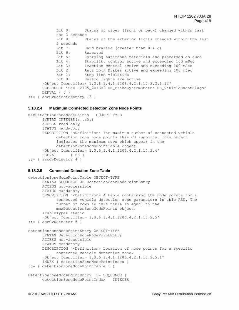
NTCIP 1202 v03A.28 Page 419
© 2019 AASHTO / ITE / NEMA Copy Per MIB Distribution Permission
Bit 9: Status of wiper (front or back) changed within last the 2 seconds
Bit 8: Status of the exterior lights changed within the last 2 seconds
Bit 7: Hard braking (greater than 0.4 g) Bit 6: Reserved Bit 5: Carrying hazardous materials and placarded as such Bit 4: Stability control active and exceeding 100 mSec Bit 3: Traction control active and exceeding 100 mSec Bit 2: Anti Lock Brakes active and exceeding 100 mSec Bit 1: Stop line violation
Bit 0: Hazard lights are active <Object Identifier> 1.3.6.1.4.1.1206.4.2.1.17.2.3.1.13" REFERENCE "SAE J2735_201603 DF_BrakeSystemStatus DE_VehicleEventFlags" DEFVAL { 0 }
::= { ascCvDetectorEntry 13 }
5.18.2.4 Maximum Connected Detection Zone Node Points maxDetectionZoneNodePoints OBJECT-TYPE
SYNTAX INTEGER(2..255) ACCESS read-only STATUS mandatory DESCRIPTION "<Definition> The maximum number of connected vehicle
detection zone node points this CU supports. This object indicates the maximum rows which appear in the detectionZoneNodePointTable object.
<Object Identifier> 1.3.6.1.4.1.1206.4.2.1.17.2.4" DEFVAL { 63 }
::= { ascCvDetector 4 }
5.18.2.5 Connected Detection Zone Table detectionZoneNodePointTable OBJECT-TYPE
SYNTAX SEQUENCE OF DetectionZoneNodePointEntry ACCESS not-accessible STATUS mandatory DESCRIPTION "<Definition> A table containing the node points for a
connected vehicle detection zone parameters in this RSU. The number of rows in this table is equal to the maxDetectionZoneNodePoints object.
<TableType> static <Object Identifier> 1.3.6.1.4.1.1206.4.2.1.17.2.5"
::= { ascCvDetector 5 }
detectionZoneNodePointEntry OBJECT-TYPE SYNTAX DetectionZoneNodePointEntry ACCESS not-accessible STATUS mandatory DESCRIPTION "<Definition> Location of node points for a specific
connected vehicle detection zone. <Object Identifier> 1.3.6.1.4.1.1206.4.2.1.17.2.5.1" INDEX { detectionZoneNodePointIndex }
::= { detectionZoneNodePointTable 1 }
DetectionZoneNodePointEntry ::= SEQUENCE { detectionZoneNodePointIndex INTEGER,

NTCIP 1202 v03A.28 Page 420
Copy Per MIB Distribution Permission © 2019 AASHTO / ITE / NEMA
detectionZoneNodePointX INTEGER, detectionZoneNodePointY INTEGER, detectionZoneNodePointWidth INTEGER, detectionZoneNodePointZ INTEGER, detectionZoneNodePointHeight INTEGER }
5.18.2.5.1 Connected Detection Zone Node Point Index detectionZoneNodePointIndex OBJECT-TYPE
SYNTAX INTEGER(1..255) ACCESS read-only STATUS mandatory DESCRIPTION "<Definition> An index for the detection zone node points
for objects in this row. This value shall not exceed the maxDetectionZoneNodePoints object value.
<Object Identifier> 1.3.6.1.4.1.1206.4.2.1.17.2.5.1.1" ::= { detectionZoneNodePointEntry 1 }
5.18.2.5.2 Detection Zone Node Point X detectionZoneNodePointX OBJECT-TYPE
SYNTAX INTEGER (-32767..32767) ACCESS read-write STATUS mandatory DESCRIPTION "<Definition>Represents the X offset, in centimeters, from
the previous node point (defined in the previous row of this table, with the first path node defined in the row detectionZoneNodePointIndex = 1). For row detectionZoneNodePointIndex = 1, the offset is from the reference point of the referenced intersection (ascCvDetectorIntersection). The sequence of nodes defines the centerline of the detection zone. A positive value is to the East.
<Object Identifier> 1.3.6.1.4.1.1206.4.2.1.17.2.5.1.2 <Unit> centimeter"
::= { detectionZoneNodePointEntry 2 }
5.18.2.5.3 Detection Zone Node Point Y detectionZoneNodePointY OBJECT-TYPE
SYNTAX INTEGER (-32767..32767) ACCESS read-write STATUS mandatory DESCRIPTION "<Definition>Represents the Y offset, in centimeters, from
the previous node point (defined in the previous row of this table, with the first node point defined in the row detectionZoneNodePointIndex = 1). For detectionZoneNodePointIndex = 1, the offset is from the reference point of the referenced intersection (ascCvDetectorIntersection). The sequence of node points defines the centerline of the zone. A positive value is to the North.
<Object Identifier> 1.3.6.1.4.1.1206.4.2.1.17.2.5.1.3 <Unit> centimeter"
::= { detectionZoneNodePointEntry 3 }

NTCIP 1202 v03A.28 Page 421
© 2019 AASHTO / ITE / NEMA Copy Per MIB Distribution Permission
5.18.2.5.4 Detection Zone Node Point Width detectionZoneNodePointWidth OBJECT-TYPE
SYNTAX INTEGER (-32767..32767) ACCESS read-write STATUS mandatory DESCRIPTION "<Definition> A value added to the current zone width at
this node and from this node onwards, in 1 centimeter steps. Lane widths between nodes are a linear taper between points.
<Object Identifier> 1.3.6.1.4.1.1206.4.2.1.17.2.5.1.4 <Unit> centimeter"
::= { detectionZoneNodePointEntry 4 }
5.18.2.5.5 Detection Zone Node Point Z detectionZoneNodePointZ OBJECT-TYPE
SYNTAX INTEGER (-32767..32767) ACCESS read-write STATUS mandatory DESCRIPTION "<Definition>Represents the Z offset, in centimeters, from
the previous node point (defined in the previous row of this table, with the first node point defined in the row detectionZoneNodePointIndex = 1). For detectionZoneNodePointIndex = 1, the offset is from the reference point of the referenced intersection (ascCvDetectorIntersection). The sequence of node points defines the elevation of the roadway pavement that the zone is on top of. A positive value represents a higher elevation.
<Object Identifier> 1.3.6.1.4.1.1206.4.2.1.17.2.5.1.5 <Unit> centimeter"
::= { detectionZoneNodePointEntry 5 }
5.18.2.5.6 Detection Zone Node Point Height detectionZoneNodePointHeight OBJECT-TYPE
SYNTAX INTEGER (0..32767) ACCESS read-write STATUS mandatory DESCRIPTION "<Definition> The height, in centimeters, above the roadway
pavement for the detection zone. This value is added to the detectionZoneNodePointZ to represent the upper boundary of the detection zone. The detection zone height between node points are a linear taper between points.
<Object Identifier> 1.3.6.1.4.1.1206.4.2.1.17.2.5.1.6 <Unit> centimeter"
::= { detectionZoneNodePointEntry 6 }
5.18.2.6 Detection Actuations Sample Period cvDetectionActuationSamplePeriod OBJECT-TYPE
SYNTAX INTEGER (0..65535) ACCESS read-write STATUS mandatory DESCRIPTION "The sample period for updating the cvDetectionActuations
object, in units of milliseconds. If the value is zero (0), then the cvDetectionActuations is not collected on a periodic basis.
<Object Identifier> 1.3.6.1.4.1.1206.4.2.1.17.2.6
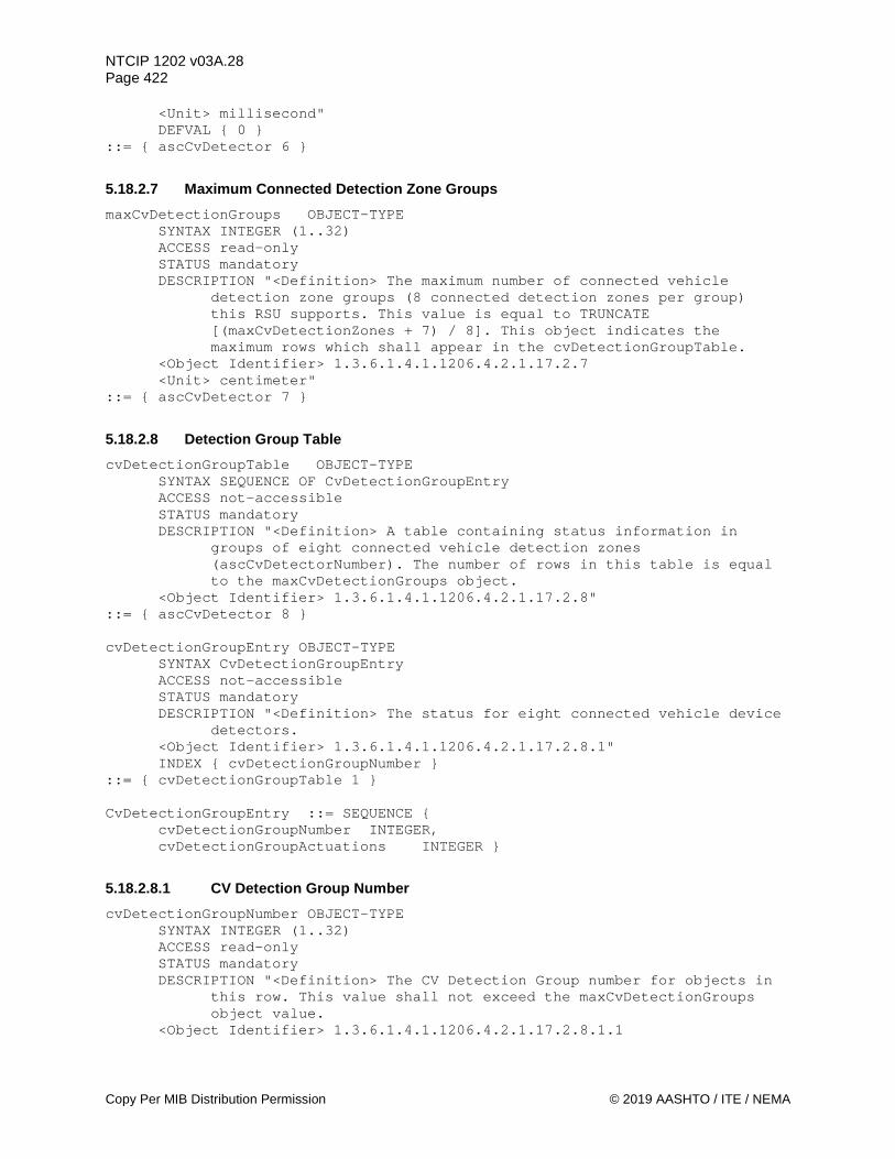
NTCIP 1202 v03A.28 Page 422
Copy Per MIB Distribution Permission © 2019 AASHTO / ITE / NEMA
<Unit> millisecond" DEFVAL { 0 }
::= { ascCvDetector 6 }
5.18.2.7 Maximum Connected Detection Zone Groups maxCvDetectionGroups OBJECT-TYPE
SYNTAX INTEGER (1..32) ACCESS read-only STATUS mandatory DESCRIPTION "<Definition> The maximum number of connected vehicle
detection zone groups (8 connected detection zones per group) this RSU supports. This value is equal to TRUNCATE [(maxCvDetectionZones + 7) / 8]. This object indicates the maximum rows which shall appear in the cvDetectionGroupTable.
<Object Identifier> 1.3.6.1.4.1.1206.4.2.1.17.2.7 <Unit> centimeter"
::= { ascCvDetector 7 }
5.18.2.8 Detection Group Table cvDetectionGroupTable OBJECT-TYPE
SYNTAX SEQUENCE OF CvDetectionGroupEntry ACCESS not-accessible STATUS mandatory DESCRIPTION "<Definition> A table containing status information in
groups of eight connected vehicle detection zones (ascCvDetectorNumber). The number of rows in this table is equal to the maxCvDetectionGroups object.
<Object Identifier> 1.3.6.1.4.1.1206.4.2.1.17.2.8" ::= { ascCvDetector 8 } cvDetectionGroupEntry OBJECT-TYPE
SYNTAX CvDetectionGroupEntry ACCESS not-accessible STATUS mandatory DESCRIPTION "<Definition> The status for eight connected vehicle device
detectors. <Object Identifier> 1.3.6.1.4.1.1206.4.2.1.17.2.8.1" INDEX { cvDetectionGroupNumber }
::= { cvDetectionGroupTable 1 } CvDetectionGroupEntry ::= SEQUENCE { cvDetectionGroupNumber INTEGER, cvDetectionGroupActuations INTEGER }
5.18.2.8.1 CV Detection Group Number cvDetectionGroupNumber OBJECT-TYPE
SYNTAX INTEGER (1..32) ACCESS read-only STATUS mandatory DESCRIPTION "<Definition> The CV Detection Group number for objects in
this row. This value shall not exceed the maxCvDetectionGroups object value.
<Object Identifier> 1.3.6.1.4.1.1206.4.2.1.17.2.8.1.1

NTCIP 1202 v03A.28 Page 423
© 2019 AASHTO / ITE / NEMA Copy Per MIB Distribution Permission
<Unit> group" ::= { cvDetectionGroupEntry 1 }
5.18.2.8.2 CV Detection Group Actuations cvDetectionGroupActuations OBJECT-TYPE
SYNTAX INTEGER (0..255) ACCESS read-only STATUS mandatory DESCRIPTION "<Definition> CV Detection Actuation Mask, where when a bit
= 1, the CV Detection is currently actuated. When a bit = 0, the CV Detection is NOT currently actuated.
Bit 7: CV Detection # = (cvDetectionGroupNumber * 8) Bit 6: CV Detection # = (cvDetectionGroupNumber * 8) - 1 Bit 5: CV Detection # = (cvDetectionGroupNumber * 8) - 2 Bit 4: CV Detection # = (cvDetectionGroupNumber * 8) - 3 Bit 3: CV Detection # = (cvDetectionGroupNumber * 8) - 4 Bit 2: CV Detection # = (cvDetectionGroupNumber * 8) - 5 Bit 1: CV Detection # = (cvDetectionGroupNumber * 8) - 6 Bit 0: CV Detection # = (cvDetectionGroupNumber * 8) - 7 <Object Identifier> 1.3.6.1.4.1.1206.4.2.1.17.2.8.1.2 <Unit> group"
::= { cvDetectionGroupEntry 2 }
5.18.2.9 CV Detection Report Collection detectionReportCollection OBJECT-TYPE
SYNTAX INTEGER (0..255) ACCESS read-write STATUS mandatory DESCRIPTION "<Definition> This object determines what pieces of data
will be exchanged and stored for the detectionReportTable. A value set to 1 indicates that piece of data shall be stored. Bit 6 & 7 = Reserved Bit 5 = platoon - detectionReportPlatoon Bit 4 = gap - detectionReportGap Bit 3 = queue length - detectionReportQueue Bit 2 = travel time - detectionReportTravelTime Bit 1 = average speed - detectionReportSpeed Bit 0 = volume - detectionReportVolume
<Object Identifier> 1.3.6.1.4.1.1206.4.2.1.17.2.9" ::= { ascCvDetector 9 }
5.18.2.10 Active CV Detectors activeCvDetectors OBJECT-TYPE
SYNTAX INTEGER (0..255) ACCESS read-only STATUS mandatory DESCRIPTION "<Definition> The number of active CV detectors in this
device. This object indicates how many rows are in the detectionReportTable object. There shall be a row for every active CV detector collecting CV data.
<Object Identifier> 1.3.6.1.4.1.1206.4.2.1.17.2.10" ::= { ascCvDetector 10 }

NTCIP 1202 v03A.28 Page 424
Copy Per MIB Distribution Permission © 2019 AASHTO / ITE / NEMA
5.18.2.11 Detection Reports Sequence detectionReportSequence OBJECT-TYPE
SYNTAX INTEGER(0..65535) ACCESS read-only STATUS mandatory DESCRIPTION "<Definition> This object defines a sequence number for
detection reports received from defined connected vehicle detection zones. This object is used to track where a new detection report received by the CU should be stored. The value cycles within the limits of 0 to 65535 and is incremented by one when a detection report is stored in the detectionReportTable.
<Object Identifier> 1.3.6.1.4.1.1206.4.2.1.17.2.11 <Unit> sequence"
::= { ascCvDetector 11 }
5.18.2.12 Connected Detection Reports Table detectionReportTable OBJECT-TYPE
SYNTAX SEQUENCE OF DetectionReportEntry ACCESS not-accessible STATUS mandatory DESCRIPTION "<Definition> A table containing detector reports for a
connected vehicle detection zone defined for this CU. The number of rows in this table is equal to the activeCvDetectors object.
Note: The objects in this table are read-write to allow the RSU to be the SNMP manager and the ASC to be the SNMP agent across the RSU - ASC interface.
<TableType> static <Object Identifier> 1.3.6.1.4.1.1206.4.2.1.17.2.12"
::= { ascCvDetector 12 }
detectionReportEntry OBJECT-TYPE SYNTAX DetectionReportEntry ACCESS not-accessible STATUS mandatory DESCRIPTION "<Definition> Detection reports received for a specific
connected vehicle detection zone. <Object Identifier> 1.3.6.1.4.1.1206.4.2.1.17.2.12.1" INDEX { ascCvDetectorNumber }
::= { detectionReportTable 1 }
DetectionReportEntry ::= SEQUENCE { detectionReportTime INTEGER, detectionReportVolume INTEGER, detectionReportSpeed INTEGER, detectionReportTravelTime INTEGER, detectionReportQueue INTEGER, detectionReportGap INTEGER, detectionReportPlatoon INTEGER }
5.18.2.12.1 Connected Detection Zone Report Time detectionReportTime OBJECT-TYPE
SYNTAX INTEGER (0..3601000) ACCESS read-write STATUS mandatory

NTCIP 1202 v03A.28 Page 425
© 2019 AASHTO / ITE / NEMA Copy Per MIB Distribution Permission
DESCRIPTION "<Definition> This object indicates the seconds within the hour the detector report is generated.
<Valid Value Rule> 0 to 3600999 are in milliseconds, with a leap second represented by 3600000 to 3600999. A value of 3601000 shall represent unavailable.
<Object Identifier> 1.3.6.1.4.1.1206.4.2.1.17.2.12.1.1 <Unit> millisecond" DEFVAL { 3601000 }
::= { detectionReportEntry 1 }
5.18.2.12.2 Connected Detection Zone Volume Data detectionReportVolume OBJECT-TYPE
SYNTAX INTEGER (0..255) ACCESS read-write STATUS mandatory DESCRIPTION "<Definition> A count of the number of connected devices
currently detected in the connected vehicle detection zone at the time the report was generated. This value shall range from 0 to 254. The value 255 shall indicate volume overflow.
<Object Identifier> 1.3.6.1.4.1.1206.4.2.1.17.2.12.1.2 <Unit> volume" DEFVAL { 0 }
::= { detectionReportEntry 2 }
5.18.2.12.3 Connected Detection Zone Speed Data detectionReportSpeed OBJECT-TYPE
SYNTAX INTEGER (0..255) ACCESS read-write STATUS mandatory DESCRIPTION "<Definition> The average speed, in 0.5 kilometers per
hour, of the connected devices currently detected in the connected vehicle detection zone at the time the report was generated.
<Valid Value Rule> A value of 0 to 253 is the average connected device speed in 0.5 kilometers per hour units. A value of 254 represents an average speed of 127 kilometers per hour or higher. A value of 255 represents an invalid or missing value.
<Object Identifier> 1.3.6.1.4.1.1206.4.2.1.17.2.12.1.3 <Unit> 0.5 kilometers/hour" DEFVAL { 255 }
::= { detectionReportEntry 3 }
5.18.2.12.4 Connected Detection Zone Travel Time Data detectionReportTravelTime OBJECT-TYPE
SYNTAX INTEGER (0..65535) ACCESS read-write STATUS mandatory DESCRIPTION "<Definition> The average travel time, in tenths of a
second, for a connected device to traverse the connected vehicle detection zone at the time the report was generated. A value of 65535 represents an invalid or missing value.
<Object Identifier> 1.3.6.1.4.1.1206.4.2.1.17.2.12.1.4 <Unit> tenth second"
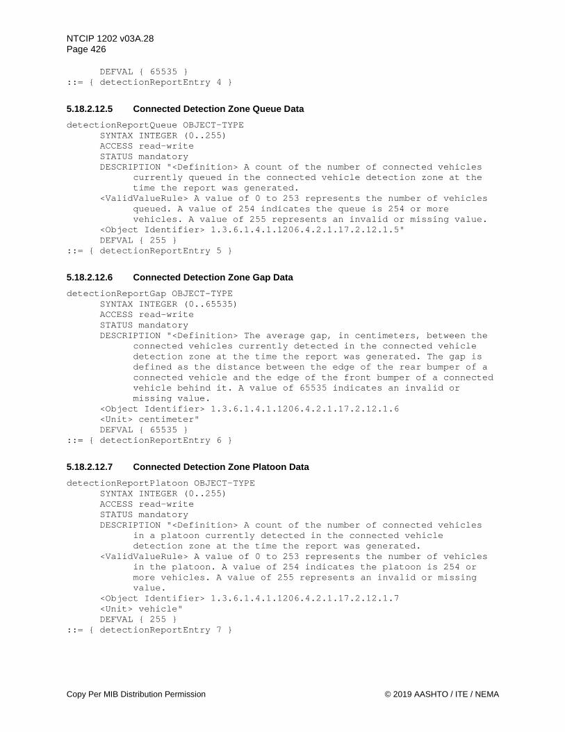
NTCIP 1202 v03A.28 Page 426
Copy Per MIB Distribution Permission © 2019 AASHTO / ITE / NEMA
DEFVAL { 65535 } ::= { detectionReportEntry 4 }
5.18.2.12.5 Connected Detection Zone Queue Data detectionReportQueue OBJECT-TYPE
SYNTAX INTEGER (0..255) ACCESS read-write STATUS mandatory DESCRIPTION "<Definition> A count of the number of connected vehicles
currently queued in the connected vehicle detection zone at the time the report was generated.
<ValidValueRule> A value of 0 to 253 represents the number of vehicles queued. A value of 254 indicates the queue is 254 or more vehicles. A value of 255 represents an invalid or missing value.
<Object Identifier> 1.3.6.1.4.1.1206.4.2.1.17.2.12.1.5" DEFVAL { 255 }
::= { detectionReportEntry 5 }
5.18.2.12.6 Connected Detection Zone Gap Data detectionReportGap OBJECT-TYPE
SYNTAX INTEGER (0..65535) ACCESS read-write STATUS mandatory DESCRIPTION "<Definition> The average gap, in centimeters, between the
connected vehicles currently detected in the connected vehicle detection zone at the time the report was generated. The gap is defined as the distance between the edge of the rear bumper of a connected vehicle and the edge of the front bumper of a connected vehicle behind it. A value of 65535 indicates an invalid or missing value.
<Object Identifier> 1.3.6.1.4.1.1206.4.2.1.17.2.12.1.6 <Unit> centimeter" DEFVAL { 65535 }
::= { detectionReportEntry 6 }
5.18.2.12.7 Connected Detection Zone Platoon Data detectionReportPlatoon OBJECT-TYPE
SYNTAX INTEGER (0..255) ACCESS read-write STATUS mandatory DESCRIPTION "<Definition> A count of the number of connected vehicles
in a platoon currently detected in the connected vehicle detection zone at the time the report was generated.
<ValidValueRule> A value of 0 to 253 represents the number of vehicles in the platoon. A value of 254 indicates the platoon is 254 or more vehicles. A value of 255 represents an invalid or missing value.
<Object Identifier> 1.3.6.1.4.1.1206.4.2.1.17.2.12.1.7 <Unit> vehicle" DEFVAL { 255 }
::= { detectionReportEntry 7 }

NTCIP 1202 v03A.28 Page 427
© 2019 AASHTO / ITE / NEMA Copy Per MIB Distribution Permission
END

NTCIP 1202 v03A.28 Page 428
Copy Per MIB Distribution Permission © 2019 AASHTO / ITE / NEMA
Section 6 Block Object Definitions
BLOCK OBJECT DEFINITIONS
6.1 Block Data Type and ID All ASC Block Objects shall begin with two octets that define the Data Type and Data ID. The Data Type octet (ascBlockDataType) provides for the definition of both NTCIP Standard and Device Proprietary data blocks. NTCIP Standard Data Blocks shall utilize an 'ascBlockDataType' of zero. Device Proprietary Data Blocks shall utilize an 'ascBlockDataType' equal to the Private Node Number (PNN) as assigned by NEMA (1.3.6.1.4.1.1206.3.PNN).
dataType Description 0x00 Standard Data Block 0XPNN Device Proprietary Data Block
The Data ID octet (ascBlockDataID) provides for definition of included data parameters. NTCIP Standard Data Blocks shall include an 'ascBlockDataID' as listed below:
ascBlockData-dataID Definitions dataID Name Description 0x00 AscPhaseBlock Phase Data (see 6.2) 0x01 AscVehDetectorBlock Vehicle Detector Data (see
6.3) 0x02 AscPedDetectorBlock Pedestrian Detector Data (see
6.4) 0x03 AscPatternBlock Pattern Data (see 6.5) 0x04 AscSplitBlock Split Data (see 6.6) 0x05 AscTimebaseBlock Time Base Data (see 6.7) 0x06 AscPreemptBlock Preempt Data (see 6.8) 0x07 AscSequenceBlock Sequence Data (see 6.9) 0x08 AscChannelBlock Channel Data (see 6.10) 0x09 AscOverlapBlock Overlap Data (see 6.11) 0x0A AscPort1Block Port 1 Data (see 6.12) 0x0B AscScheduleBlock Schedule Data (see 6.13) 0x0C AscDayPlanBlock Day Plan Data (see 6.14) 0x0D AscEventConfigBlock Event Config Data (see 6.15) 0x0E AscEventClassBlock Event Class Data (see 6.16) 0x0F AscDynObjConfigBlock (*) Dynamic Object Config Data
(see 6.17) 0x10 AscDynObjOwnerBlock (*) Dynamic Object Owner Data
(see 6.18) 0x11 AscDynObjStatusBlock (*) Dynamic Object Status Data
(see 6.19) 0x12 AscMiscBlock Miscellaneous ASC Data (see
6.20) 0x13 AscPhase2Block Phase 2 Data (see 6.21) 0x14 AscVehDetector2Block Vehicle Detector 2 Data (See
6.22)
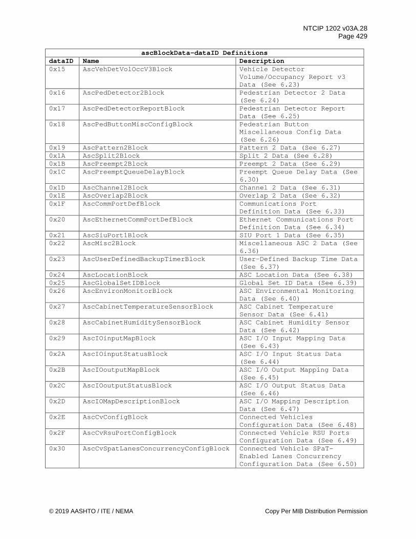
NTCIP 1202 v03A.28 Page 429
© 2019 AASHTO / ITE / NEMA Copy Per MIB Distribution Permission
ascBlockData-dataID Definitions dataID Name Description 0x15 AscVehDetVolOccV3Block Vehicle Detector
Volume/Occupancy Report v3 Data (See 6.23)
0x16 AscPedDetector2Block Pedestrian Detector 2 Data (See 6.24)
0x17 AscPedDetectorReportBlock Pedestrian Detector Report Data (See 6.25)
0x18 AscPedButtonMiscConfigBlock Pedestrian Button Miscellaneous Config Data (See 6.26)
0x19 AscPattern2Block Pattern 2 Data (See 6.27) 0x1A AscSplit2Block Split 2 Data (See 6.28) 0x1B AscPreempt2Block Preempt 2 Data (See 6.29) 0x1C AscPreemptQueueDelayBlock Preempt Queue Delay Data (See
6.30) 0x1D AscChannel2Block Channel 2 Data (See 6.31) 0x1E AscOverlap2Block Overlap 2 Data (See 6.32) 0x1F AscCommPortDefBlock Communications Port
Definition Data (See 6.33) 0x20 AscEthernetCommPortDefBlock Ethernet Communications Port
Definition Data (See 6.34) 0x21 AscSiuPort1Block SIU Port 1 Data (See 6.35) 0x22 AscMisc2Block Miscellaneous ASC 2 Data (See
6.36) 0x23 AscUserDefinedBackupTimerBlock User-Defined Backup Time Data
(See 6.37) 0x24 AscLocationBlock ASC Location Data (See 6.38) 0x25 AscGlobalSetIDBlock Global Set ID Data (See 6.39) 0x26 AscEnvironMonitorBlock ASC Environmental Monitoring
Data (See 6.40) 0x27 AscCabinetTemperatureSensorBlock ASC Cabinet Temperature
Sensor Data (See 6.41) 0x28 AscCabinetHumiditySensorBlock ASC Cabinet Humidity Sensor
Data (See 6.42) 0x29 AscIOinputMapBlock ASC I/O Input Mapping Data
(See 6.43) 0x2A AscIOinputStatusBlock ASC I/O Input Status Data
(See 6.44) 0x2B AscIOoutputMapBlock ASC I/O Output Mapping Data
(See 6.45) 0x2C AscIOoutputStatusBlock ASC I/O Output Status Data
(See 6.46) 0x2D AscIOMapDescriptionBlock ASC I/O Mapping Description
Data (See 6.47) 0x2E AscCvConfigBlock Connected Vehicles
Configuration Data (See 6.48) 0x2F AscCvRsuPortConfigBlock Connected Vehicle RSU Ports
Configuration Data (See 6.49) 0x30 AscCvSpatLanesConcurrencyConfigBlock Connected Vehicle SPaT-
Enabled Lanes Concurrency Configuration Data (See 6.50)
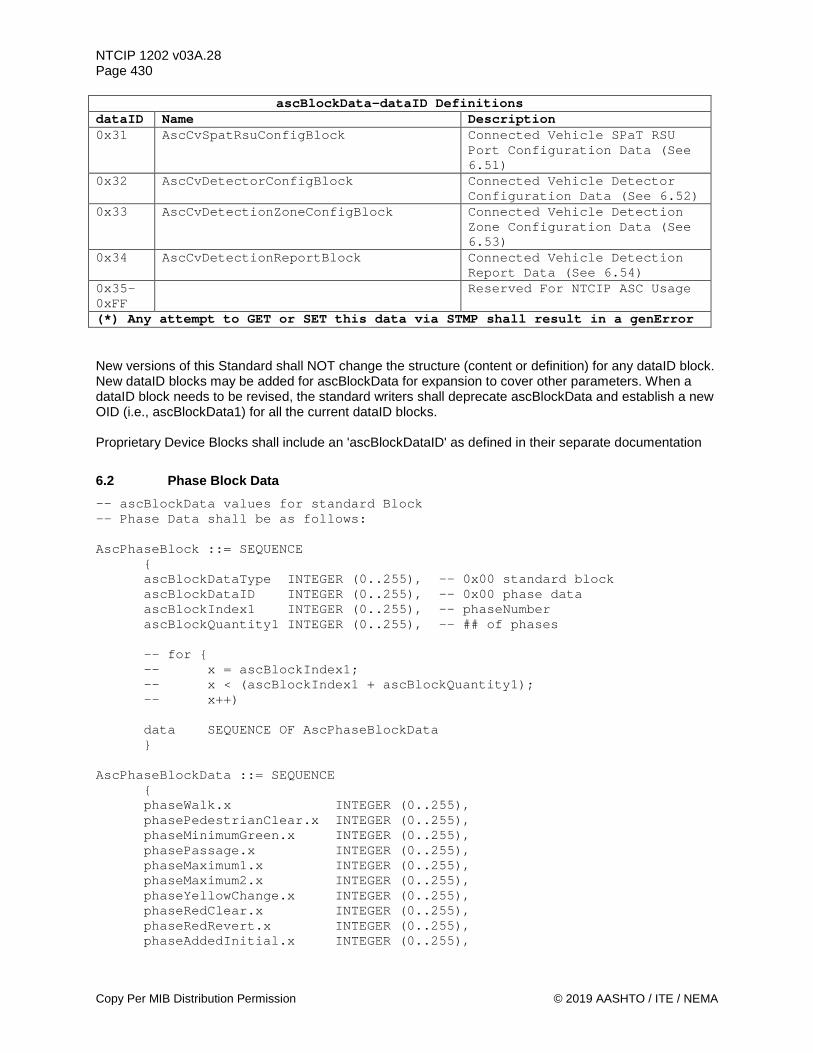
NTCIP 1202 v03A.28 Page 430
Copy Per MIB Distribution Permission © 2019 AASHTO / ITE / NEMA
ascBlockData-dataID Definitions dataID Name Description 0x31 AscCvSpatRsuConfigBlock Connected Vehicle SPaT RSU
Port Configuration Data (See 6.51)
0x32 AscCvDetectorConfigBlock Connected Vehicle Detector Configuration Data (See 6.52)
0x33 AscCvDetectionZoneConfigBlock Connected Vehicle Detection Zone Configuration Data (See 6.53)
0x34 AscCvDetectionReportBlock Connected Vehicle Detection Report Data (See 6.54)
0x35-0xFF
Reserved For NTCIP ASC Usage
(*) Any attempt to GET or SET this data via STMP shall result in a genError New versions of this Standard shall NOT change the structure (content or definition) for any dataID block. New dataID blocks may be added for ascBlockData for expansion to cover other parameters. When a dataID block needs to be revised, the standard writers shall deprecate ascBlockData and establish a new OID (i.e., ascBlockData1) for all the current dataID blocks. Proprietary Device Blocks shall include an 'ascBlockDataID' as defined in their separate documentation
6.2 Phase Block Data -- ascBlockData values for standard Block -- Phase Data shall be as follows: AscPhaseBlock ::= SEQUENCE
{ ascBlockDataType INTEGER (0..255), -- 0x00 standard block ascBlockDataID INTEGER (0..255), -- 0x00 phase data ascBlockIndex1 INTEGER (0..255), -- phaseNumber ascBlockQuantity1 INTEGER (0..255), -- ## of phases -- for { -- x = ascBlockIndex1; -- x < (ascBlockIndex1 + ascBlockQuantity1); -- x++) data SEQUENCE OF AscPhaseBlockData }
AscPhaseBlockData ::= SEQUENCE
{ phaseWalk.x INTEGER (0..255), phasePedestrianClear.x INTEGER (0..255), phaseMinimumGreen.x INTEGER (0..255), phasePassage.x INTEGER (0..255), phaseMaximum1.x INTEGER (0..255), phaseMaximum2.x INTEGER (0..255), phaseYellowChange.x INTEGER (0..255), phaseRedClear.x INTEGER (0..255), phaseRedRevert.x INTEGER (0..255), phaseAddedInitial.x INTEGER (0..255),
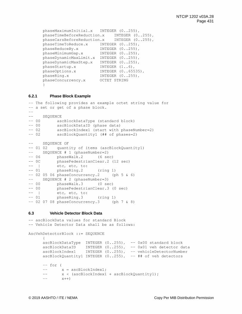
NTCIP 1202 v03A.28 Page 431
© 2019 AASHTO / ITE / NEMA Copy Per MIB Distribution Permission
phaseMaximumInitial.x INTEGER (0..255), phaseTimeBeforeReduction.x INTEGER (0..255), phaseCarsBeforeReduction.x INTEGER (0..255), phaseTimeToReduce.x INTEGER (0..255), phaseReduceBy.x INTEGER (0..255), phaseMinimumGap.x INTEGER (0..255), phaseDynamicMaxLimit.x INTEGER (0..255), phaseDynamicMaxStep.x INTEGER (0..255), phaseStartup.x INTEGER (1..6), phaseOptions.x INTEGER (0..65535), phaseRing.x INTEGER (0..255), phaseConcurrency.x OCTET STRING }
6.2.1 Phase Block Example -- The following provides an example octet string value for -- a set or get of a phase block. -- -- SEQUENCE -- 00 ascBlockDataType (standard block) -- 00 ascBlockDataID (phase data) -- 02 ascBlockIndex1 (start with phaseNumber=2) -- 02 ascBlockQuantity1 (## of phases=2) -- SEQUENCE OF -- 01 02 quantity of items (ascBlockQuantity1) -- SEQUENCE # 1 (phaseNumber=2) -- 06 phaseWalk.2 (6 sec) -- 0C phasePedestrianClear.2 (12 sec) -- | etc, etc, to: -- 01 phaseRing.2 (ring 1) -- 02 05 06 phaseConcurrency.2 (ph 5 & 6) -- SEQUENCE # 2 (phaseNumber=3) -- 00 phaseWalk.3 (0 sec) -- 00 phasePedestrianClear.3 (0 sec) -- | etc, etc, to: -- 01 phaseRing.3 (ring 1) -- 02 07 08 phaseConcurrency.3 (ph 7 & 8)
6.3 Vehicle Detector Block Data -- ascBlockData values for standard Block -- Vehicle Detector Data shall be as follows: AscVehDetectorBlock ::= SEQUENCE
{ ascBlockDataType INTEGER (0..255), -- 0x00 standard block ascBlockDataID INTEGER (0..255), -- 0x01 veh detector data ascBlockIndex1 INTEGER (0..255), -- vehicleDetectorNumber ascBlockQuantity1 INTEGER (0..255), -- ## of veh detectors -- for ( -- x = ascBlockIndex1; -- x < (ascBlockIndex1 + ascBlockQuantity1); -- x++)

NTCIP 1202 v03A.28 Page 432
Copy Per MIB Distribution Permission © 2019 AASHTO / ITE / NEMA
data SEQUENCE OF AscVehDetectorBlockData }
AscVehDetectorBlockData ::= SEQUENCE
{ vehicleDetectorOptions.x INTEGER (0..255), vehicleDetectorCallPhase.x INTEGER (0..255), vehicleDetectorSwitchPhase.x INTEGER (0..255), vehicleDetectorDelay.x INTEGER (0..65535), vehicleDetectorExtend.x INTEGER (0..255), vehicleDetectorQueueLimit.x INTEGER (0..255), vehicleDetectorNoActivity.x INTEGER (0..255), vehicleDetectorMaxPresence.x INTEGER (0..255), vehicleDetectorErraticCounts.x INTEGER (0..255), vehicleDetectorFailTime.x INTEGER (0..255) }
6.3.1 Vehicle Detector Block Example -- The following provides an example octet string value for -- a set or get of a vehicle detector block. -- -- SEQUENCE -- 00 ascBlockDataType (standard block) -- 01 ascBlockDataID (veh detector data) -- 02 ascBlockIndex1 (start with vehicleDetectorNumber=2) -- 02 ascBlockQuantity1 (## of veh det=2) -- SEQUENCE OF -- 01 02 quantity of items (ascBlockQuantity1) -- SEQUENCE # 1 (vehicleDetectorNumber =2) -- B4 vehicleDetectorOptions.2 (bits) -- 02 vehicleDetectorCallPhase.2 (ph 2) -- | etc, etc, to: -- 00 vehicleDetectorErraticCounts.2 (0 cpm) -- FF vehicleDetectorFailTime.2 (255 sec) -- SEQUENCE # 2 (vehicleDetectorNumber =3) -- B4 vehicleDetectorOptions.3 (bits) -- 03 vehicleDetectorCallPhase.3 (ph 3) -- | etc, etc, to: -- 00 vehicleDetectorErraticCounts.3 (0 cpm) -- FF vehicleDetectorFailTime.3 (255 sec)
6.4 Pedestrian Detector Block Data -- ascBlockData values for standard Block -- Pedestrian Detector Data shall be as follows: AscPedDetectorBlock ::= SEQUENCE
{ ascBlockDataType INTEGER (0..255), -- 0x00 standard block ascBlockDataID INTEGER (0..255), -- 0x02 ped detector data ascBlockIndex1 INTEGER (0..255), -- pedestrianDetectorNumber ascBlockQuantity1 INTEGER (0..255), -- ## of ped detectors -- for ( -- x = ascBlockIndex1;
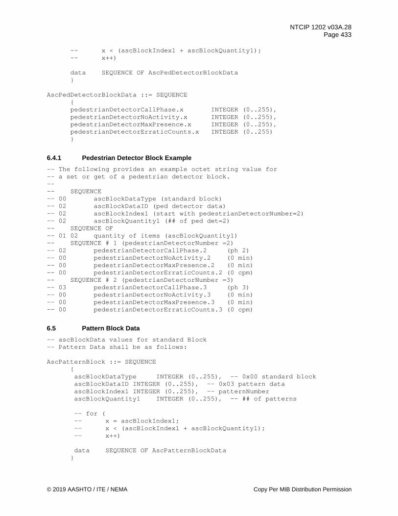
NTCIP 1202 v03A.28 Page 433
© 2019 AASHTO / ITE / NEMA Copy Per MIB Distribution Permission
-- x < (ascBlockIndex1 + ascBlockQuantity1); -- x++) data SEQUENCE OF AscPedDetectorBlockData }
AscPedDetectorBlockData ::= SEQUENCE
{ pedestrianDetectorCallPhase.x INTEGER (0..255), pedestrianDetectorNoActivity.x INTEGER (0..255), pedestrianDetectorMaxPresence.x INTEGER (0..255), pedestrianDetectorErraticCounts.x INTEGER (0..255) }
6.4.1 Pedestrian Detector Block Example -- The following provides an example octet string value for -- a set or get of a pedestrian detector block. -- -- SEQUENCE -- 00 ascBlockDataType (standard block) -- 02 ascBlockDataID (ped detector data) -- 02 ascBlockIndex1 (start with pedestrianDetectorNumber=2) -- 02 ascBlockQuantity1 (## of ped det=2) -- SEQUENCE OF -- 01 02 quantity of items (ascBlockQuantity1) -- SEQUENCE # 1 (pedestrianDetectorNumber =2) -- 02 pedestrianDetectorCallPhase.2 (ph 2) -- 00 pedestrianDetectorNoActivity.2 (0 min) -- 00 pedestrianDetectorMaxPresence.2 (0 min) -- 00 pedestrianDetectorErraticCounts.2 (0 cpm) -- SEQUENCE # 2 (pedestrianDetectorNumber =3) -- 03 pedestrianDetectorCallPhase.3 (ph 3) -- 00 pedestrianDetectorNoActivity.3 (0 min) -- 00 pedestrianDetectorMaxPresence.3 (0 min) -- 00 pedestrianDetectorErraticCounts.3 (0 cpm)
6.5 Pattern Block Data -- ascBlockData values for standard Block -- Pattern Data shall be as follows: AscPatternBlock ::= SEQUENCE
{ ascBlockDataType INTEGER (0..255), -- 0x00 standard block ascBlockDataID INTEGER (0..255), -- 0x03 pattern data ascBlockIndex1 INTEGER (0..255), -- patternNumber ascBlockQuantity1 INTEGER (0..255), -- ## of patterns -- for ( -- x = ascBlockIndex1; -- x < (ascBlockIndex1 + ascBlockQuantity1); -- x++) data SEQUENCE OF AscPatternBlockData }

NTCIP 1202 v03A.28 Page 434
Copy Per MIB Distribution Permission © 2019 AASHTO / ITE / NEMA
AscPatternBlockData ::= SEQUENCE { patternCycleTime.x INTEGER (0..255), patternOffsetTime.x INTEGER (0..255), patternSequenceNumber.x INTEGER (0..255) }
6.5.1 Pattern Block Example -- The following provides an example octet string value for -- a set or get of a pattern block. -- -- SEQUENCE -- 00 ascBlockDataType (standard block) -- 03 ascBlockDataID (pattern data) -- 02 ascBlockIndex1 (start with patternNumber=2) -- 02 ascBlockQuantity1 (## of patterns=2) -- SEQUENCE OF -- 01 02 quantity of items (ascBlockQuantity1) -- SEQUENCE # 1 (patternNumber =2) -- 50 patternCycleTime.2 (80 sec) -- 00 patternOffsetTime.2 (0 sec) -- 01 patternSequenceNumber.2 (seq 1) -- SEQUENCE # 2 (patternNumber =3) -- 64 patternCycleTime.3 (100 sec) -- 05 patternOffsetTime.3 (5 sec) -- 01 patternSequenceNumber.3 (seq 1)
6.6 Split Block Data -- ascBlockData values for standard Block -- Split Data shall be as follows: AscSplitBlock ::= SEQUENCE
{ ascBlockDataType INTEGER (0..255), -- 0x00 standard block ascBlockDataID INTEGER (0..255), -- 0x04 split data ascBlockIndex1 INTEGER (0..255), -- splitPhase ascBlockQuantity1 INTEGER (0..255), -- ## of phases ascBlockIndex2 INTEGER (0..255), -- splitNumber ascBlockQuantity2 INTEGER (0..255), -- ## of splits -- for ( -- y = ascBlockIndex2; -- y < (ascBlockIndex2 + ascBlockQuantity2); -- y++) -- for ( -- x = ascBlockIndex1; -- x < (ascBlockIndex1 + ascBlockQuantity1); -- x++) data SEQUENCE OF AscSplitBlockData }
AscSplitBlockData ::= SEQUENCE
{ splitTime.y.x INTEGER (0..255),

NTCIP 1202 v03A.28 Page 435
© 2019 AASHTO / ITE / NEMA Copy Per MIB Distribution Permission
splitMode.y.x INTEGER (1..7), splitCoordPhase.y.x INTEGER (0..1) }
6.6.1 Split Block Example -- The following provides an example octet string value for -- a set or get of a split block. -- -- SEQUENCE -- 00 ascBlockDataType (standard block) -- 04 ascBlockDataID (split data) -- 01 ascBlockIndex1 (start with splitPhase=1) -- 02 ascBlockQuantity1 (## of phases=2) -- 01 ascBlockIndex2 (start with splitNumber=1) -- 02 ascBlockQuantity2 (## of splits=2) -- SEQUENCE OF -- 01 04 quantity of items (ascBlockQuantity1 * ascBlockQuantity2) -- SEQUENCE # 1 (splitNumber=1 / splitPhase=1) -- 14 splitTime.1.1 (20 sec) -- 02 splitMode.1.1 (none) -- 00 splitCoordPhase.1.1 (false) -- SEQUENCE # 2 (splitNumber=1 / splitPhase=2) -- 14 splitTime.1.2 (20 sec) -- 02 splitMode.1.2 (none) -- 01 splitCoordPhase.1.2 (true) -- SEQUENCE # 3 (splitNumber=2 / splitPhase=1) -- 19 splitTime.2.1 (25 sec) -- 02 splitMode.2.1 (none) -- 00 splitCoordPhase.2.1 (false) -- SEQUENCE # 4 (splitNumber=2 / splitPhase=2) -- 19 splitTime.2.2 (25 sec) -- 02 splitMode.2.2 (none) -- 01 splitCoordPhase.2.2 (true)
6.7 Time Base Block Data -- ascBlockData values for standard Block -- Time Base Data shall be as follows: AscTimebaseBlock ::= SEQUENCE
{ ascBlockDataType INTEGER (0..255), -- 0x00 standard block ascBlockDataID INTEGER (0..255), -- 0x05 time base data ascBlockIndex1 INTEGER (0..255), -- timebaseAscActionNumber ascBlockQuantity1 INTEGER (0..255), -- ## of actions -- for ( -- x = ascBlockIndex1; -- x < (ascBlockIndex1 + ascBlockQuantity1); -- x++) data SEQUENCE OF AscTimebaseBlockData }
AscTimebaseBlockData ::= SEQUENCE
{
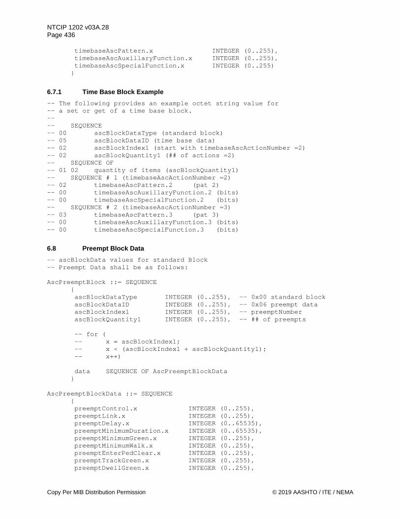
NTCIP 1202 v03A.28 Page 436
Copy Per MIB Distribution Permission © 2019 AASHTO / ITE / NEMA
timebaseAscPattern.x INTEGER (0..255), timebaseAscAuxillaryFunction.x INTEGER (0..255), timebaseAscSpecialFunction.x INTEGER (0..255) }
6.7.1 Time Base Block Example -- The following provides an example octet string value for -- a set or get of a time base block. -- -- SEQUENCE -- 00 ascBlockDataType (standard block) -- 05 ascBlockDataID (time base data) -- 02 ascBlockIndex1 (start with timebaseAscActionNumber =2) -- 02 ascBlockQuantity1 (## of actions =2) -- SEQUENCE OF -- 01 02 quantity of items (ascBlockQuantity1) -- SEQUENCE # 1 (timebaseAscActionNumber =2) -- 02 timebaseAscPattern.2 (pat 2) -- 00 timebaseAscAuxillaryFunction.2 (bits) -- 00 timebaseAscSpecialFunction.2 (bits) -- SEQUENCE # 2 (timebaseAscActionNumber =3) -- 03 timebaseAscPattern.3 (pat 3) -- 00 timebaseAscAuxillaryFunction.3 (bits) -- 00 timebaseAscSpecialFunction.3 (bits)
6.8 Preempt Block Data -- ascBlockData values for standard Block -- Preempt Data shall be as follows: AscPreemptBlock ::= SEQUENCE
{ ascBlockDataType INTEGER (0..255), -- 0x00 standard block ascBlockDataID INTEGER (0..255), -- 0x06 preempt data ascBlockIndex1 INTEGER (0..255), -- preemptNumber ascBlockQuantity1 INTEGER (0..255), -- ## of preempts -- for ( -- x = ascBlockIndex1; -- x < (ascBlockIndex1 + ascBlockQuantity1); -- x++) data SEQUENCE OF AscPreemptBlockData }
AscPreemptBlockData ::= SEQUENCE
{ preemptControl.x INTEGER (0..255), preemptLink.x INTEGER (0..255), preemptDelay.x INTEGER (0..65535), preemptMinimumDuration.x INTEGER (0..65535), preemptMinimumGreen.x INTEGER (0..255), preemptMinimumWalk.x INTEGER (0..255), preemptEnterPedClear.x INTEGER (0..255), preemptTrackGreen.x INTEGER (0..255), preemptDwellGreen.x INTEGER (0..255),
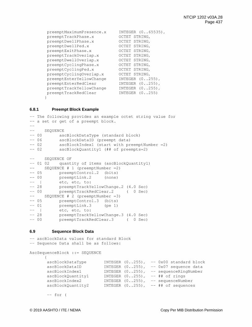
NTCIP 1202 v03A.28 Page 437
© 2019 AASHTO / ITE / NEMA Copy Per MIB Distribution Permission
preemptMaximumPresence.x INTEGER (0..65535), preemptTrackPhase.x OCTET STRING, preemptDwellPhase.x OCTET STRING, preemptDwellPed.x OCTET STRING, preemptExitPhase.x OCTET STRING, preemptTrackOverlap.x OCTET STRING, preemptDwellOverlap.x OCTET STRING, preemptCyclingPhase.x OCTET STRING, preemptCyclingPed.x OCTET STRING, preemptCyclingOverlap.x OCTET STRING, preemptEnterYellowChange INTEGER (0..255), preemptEnterRedClear INTEGER (0..255), preemptTrackYellowChange INTEGER (0..255), preemptTrackRedClear INTEGER (0..255) }
6.8.1 Preempt Block Example -- The following provides an example octet string value for -- a set or get of a preempt block. -- -- SEQUENCE -- 00 ascBlockDataType (standard block) -- 06 ascBlockDataID (preempt data) -- 02 ascBlockIndex1 (start with preemptNumber =2) -- 02 ascBlockQuantity1 (## of preempts=2) -- SEQUENCE OF -- 01 02 quantity of items (ascBlockQuantity1) -- SEQUENCE # 1 (preemptNumber =2) -- 05 preemptControl.2 (bits) -- 00 preemptLink.2 (none) -- | etc, etc, to: -- 28 preemptTrackYellowChange.2 (4.0 Sec) -- 00 preemptTrackRedClear.2 ( 0 Sec) -- SEQUENCE # 2 (preemptNumber =3) -- 05 preemptControl.3 (bits) -- 01 preemptLink.3 (pe 1) -- | etc, etc, to: -- 28 preemptTrackYellowChange.3 (4.0 Sec) -- 00 preemptTrackRedClear.3 ( 0 Sec)
6.9 Sequence Block Data -- ascBlockData values for standard Block -- Sequence Data shall be as follows: AscSequenceBlock ::= SEQUENCE
{ ascBlockDataType INTEGER (0..255), -- 0x00 standard block ascBlockDataID INTEGER (0..255), -- 0x07 sequence data ascBlockIndex1 INTEGER (0..255), -- sequenceRingNumber ascBlockQuantity1 INTEGER (0..255), -- ## of rings ascBlockIndex2 INTEGER (0..255), -- sequenceNumber ascBlockQuantity2 INTEGER (0..255), -- ## of sequences -- for (

NTCIP 1202 v03A.28 Page 438
Copy Per MIB Distribution Permission © 2019 AASHTO / ITE / NEMA
-- y = ascBlockIndex2; -- y < (ascBlockIndex2 + ascBlockQuantity2); -- y++) -- for ( -- x = ascBlockIndex1; -- x < (ascBlockIndex1 + ascBlockQuantity1); -- x++) data SEQUENCE OF AscSequenceBlockData }
AscSequenceBlockData ::= SEQUENCE
{ sequenceData.y.x OCTET STRING }
6.9.1 Sequence Block Example -- The following provides an example octet string value for -- a set or get of a sequence block. -- -- SEQUENCE -- 00 ascBlockDataType (standard block) -- 07 ascBlockDataID (sequence data) -- 01 ascBlockIndex1 (start with sequenceRingNumber=1) -- 02 ascBlockQuantity1 (## of rings=2) -- 01 ascBlockIndex2 (start with sequenceNumber=1) -- 02 ascBlockQuantity2 (## of sequences =2) -- SEQUENCE OF -- 01 04 quantity of items (ascBlockQuantity1 * ascBlockQuantity2) -- SEQUENCE # 1 (sequenceNumber=1 / sequenceRingNumber=1) -- 04 01 02 03 04 sequenceData.1.1 (ph 1-2-3-4) -- SEQUENCE # 2 (sequenceNumber=1 / sequenceRingNumber=2) -- 04 05 06 07 08 sequenceData.1.2 (ph 5-6-7-8) -- SEQUENCE # 3 (sequenceNumber=2 / sequenceRingNumber=1) -- 04 02 01 04 03 sequenceData.2.1 (ph 1-2-3-4) -- SEQUENCE # 4 (sequenceNumber=2 / sequenceRingNumber=2) -- 04 06 05 08 07 sequenceData.2.2 (ph 5-6-7-8)
6.10 Channel Block Data -- ascBlockData values for standard Block -- Channel Data shall be as follows: AscChannelBlock ::= SEQUENCE
{ ascBlockDataType INTEGER (0..255), -- 0x00 standard block ascBlockDataID INTEGER (0..255), -- 0x08 channel data ascBlockIndex1 INTEGER (0..255), -- channelNumber ascBlockQuantity1 INTEGER (0..255), -- ## of channels -- for ( -- x = ascBlockIndex1; -- x < (ascBlockIndex1 + ascBlockQuantity1); -- x++) data SEQUENCE OF AscChannelBlockData

NTCIP 1202 v03A.28 Page 439
© 2019 AASHTO / ITE / NEMA Copy Per MIB Distribution Permission
} AscChannelBlockData ::= SEQUENCE
{ channelControlSource.x INTEGER (0..255), channelControlType.x INTEGER (1..4), channelFlash.x INTEGER (0..255), channelDim.x INTEGER (0..255) }
6.10.1 Channel Block Example -- The following provides an example octet string value for -- a SET or GET of a channel block. -- -- SEQUENCE -- 00 ascBlockDataType (standard block) -- 08 ascBlockDataID (channel data) -- 02 ascBlockIndex1 (start with channelNumber=2) -- 02 ascBlockQuantity1 (## of channels=2) -- SEQUENCE OF -- 01 02 quantity of items (ascBlockQuantity1) -- SEQUENCE # 1 (channelNumber=2) -- 02 channelControlSource.2 (ph 2) -- 02 channelControlType.2 (phaseVehicle) -- 02 channelFlash.2 (bits) -- 07 channelDim.2 (bits) -- SEQUENCE # 2 (channelNumber=3) -- 03 channelControlSource.3 (ph 3) -- 02 channelControlType.3 (phaseVehicle) -- 04 channelFlash.3 (bits) -- 0F channelDim.3 (bits)
6.11 Overlap Block Data -- ascBlockData values for standard Block -- Overlap Data shall be as follows: AscOverlapBlock ::= SEQUENCE
{ ascBlockDataType INTEGER (0..255), -- 0x00 standard block ascBlockDataID INTEGER (0..255), -- 0x09 overlap data ascBlockIndex1 INTEGER (0..255), -- overlapNumber ascBlockQuantity1 INTEGER (0..255), -- ## of overlaps -- for ( -- x = ascBlockIndex1; -- x < (ascBlockIndex1 + ascBlockQuantity1); -- x++) data SEQUENCE OF AscOverlapBlockData }
AscOverlapBlockData ::= SEQUENCE
{ overlapIncludedPhases.x OCTET STRING, overlapModifierPhases.x OCTET STRING,
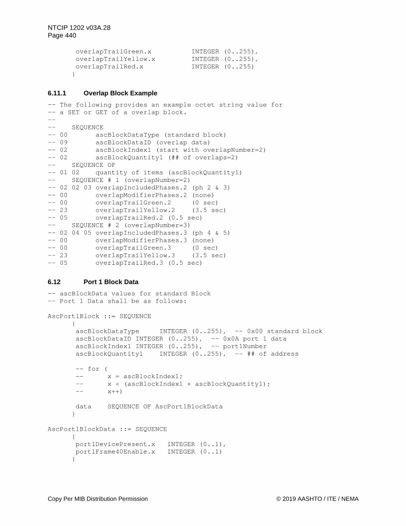
NTCIP 1202 v03A.28 Page 440
Copy Per MIB Distribution Permission © 2019 AASHTO / ITE / NEMA
overlapTrailGreen.x INTEGER (0..255), overlapTrailYellow.x INTEGER (0..255), overlapTrailRed.x INTEGER (0..255) }
6.11.1 Overlap Block Example -- The following provides an example octet string value for -- a SET or GET of a overlap block. -- -- SEQUENCE -- 00 ascBlockDataType (standard block) -- 09 ascBlockDataID (overlap data) -- 02 ascBlockIndex1 (start with overlapNumber=2) -- 02 ascBlockQuantity1 (## of overlaps=2) -- SEQUENCE OF -- 01 02 quantity of items (ascBlockQuantity1) -- SEQUENCE # 1 (overlapNumber=2) -- 02 02 03 overlapIncludedPhases.2 (ph 2 & 3) -- 00 overlapModifierPhases.2 (none) -- 00 overlapTrailGreen.2 (0 sec) -- 23 overlapTrailYellow.2 (3.5 sec) -- 05 overlapTrailRed.2 (0.5 sec) -- SEQUENCE # 2 (overlapNumber=3) -- 02 04 05 overlapIncludedPhases.3 (ph 4 & 5) -- 00 overlapModifierPhases.3 (none) -- 00 overlapTrailGreen.3 (0 sec) -- 23 overlapTrailYellow.3 (3.5 sec) -- 05 overlapTrailRed.3 (0.5 sec)
6.12 Port 1 Block Data -- ascBlockData values for standard Block -- Port 1 Data shall be as follows: AscPort1Block ::= SEQUENCE
{ ascBlockDataType INTEGER (0..255), -- 0x00 standard block ascBlockDataID INTEGER (0..255), -- 0x0A port 1 data ascBlockIndex1 INTEGER (0..255), -- port1Number ascBlockQuantity1 INTEGER (0..255), -- ## of address -- for ( -- x = ascBlockIndex1; -- x < (ascBlockIndex1 + ascBlockQuantity1); -- x++) data SEQUENCE OF AscPort1BlockData }
AscPort1BlockData ::= SEQUENCE
{ port1DevicePresent.x INTEGER (0..1), port1Frame40Enable.x INTEGER (0..1) }

NTCIP 1202 v03A.28 Page 441
© 2019 AASHTO / ITE / NEMA Copy Per MIB Distribution Permission
6.12.1 Port 1 Block Example -- The following provides an example octet string value for -- a SET or GET of a port 1 block. -- -- SEQUENCE -- 00 ascBlockDataType (standard block) -- 0A ascBlockDataID (port 1 data) -- 02 ascBlockIndex1 (start with port1Number=2) -- 02 ascBlockQuantity1 (## of address=2) -- SEQUENCE OF -- 01 02 quantity of items (ascBlockQuantity1) -- SEQUENCE # 1 (port1Number=2) -- 01 port1DevicePresent.2 (true) -- 00 port1Frame40Enable.2 (false) -- SEQUENCE # 2 (port1Number=3) -- 01 port1DevicePresent.3 (true) -- 00 port1Frame40Enable.3 (false)
6.13 Schedule Block Data -- ascBlockData values for standard Block -- Schedule Data shall be as follows: AscScheduleBlock ::= SEQUENCE
{ ascBlockDataType INTEGER (0..255), -- 0x00 standard block ascBlockDataID INTEGER (0..255), -- 0x0B schedule data ascBlockIndex1 INTEGER (0..255), -- timeBaseScheduleNumber ascBlockQuantity1 INTEGER (0..255), -- ## of schedules -- for ( -- x = ascBlockIndex1; -- x < (ascBlockIndex1 + ascBlockQuantity1); -- x++) data SEQUENCE OF AscScheduleBlockData }
AscScheduleBlockData ::= SEQUENCE
{ timeBaseScheduleMonth.x INTEGER (0..65535), timeBaseScheduleDay.x INTEGER (0..255), timeBaseScheduleDate.x INTEGER (0..4294967295), timeBaseScheduleDayPlan.x INTEGER (1..255) }
6.13.1 Schedule Block Example -- The following provides an example octet string value for -- a set or get of a schedule block. -- -- SEQUENCE -- 00 ascBlockDataType (standard block) -- 0B ascBlockDataID (schedule data) -- 02 ascBlockIndex1 (start with timeBaseScheduleNumber=2) -- 02 ascBlockQuantity1 (## of schedules=2)

NTCIP 1202 v03A.28 Page 442
Copy Per MIB Distribution Permission © 2019 AASHTO / ITE / NEMA
-- SEQUENCE OF -- 01 02 quantity of items (ascBlockQuantity1) -- SEQUENCE # 1 (timeBaseScheduleNumber=2) -- 1F FE timeBaseScheduleMonth.2 (all) -- 04 timeBaseScheduleDay.2 (Mon) -- FF FF FF FE timeBaseScheduleDate.2 (all) -- 02 timeBaseScheduleDayPlan.2 (dp 2) -- SEQUENCE # 2 (timeBaseScheduleNumber=3) -- 1F FE timeBaseScheduleMonth.3 (all) -- 08 timeBaseScheduleDay.3 (Tue) -- FF FF FF FE timeBaseScheduleDate.3 (all) -- 03 timeBaseScheduleDayPlan.3 (dp 3)
6.14 Day Plan Block Data -- ascBlockData values for standard Block -- Day Plan Data shall be as follows: AscDayPlanBlock ::= SEQUENCE
{ ascBlockDataType INTEGER (0..255), -- 0x00 standard block ascBlockDataID INTEGER (0..255), -- 0x0C day plan data ascBlockIndex1 INTEGER (0..255), -- dayPlanEventNumber ascBlockQuantity1 INTEGER (0..255), -- ## of day plan events ascBlockIndex2 INTEGER (0..255), -- dayPlanNumber ascBlockQuantity2 INTEGER (0..255), -- ## of day plans -- for ( -- y = ascBlockIndex2; -- y < (ascBlockIndex2 + ascBlockQuantity2); -- y++) -- for ( -- x = ascBlockIndex1; -- x < (ascBlockIndex1 + ascBlockQuantity1); -- x++) data SEQUENCE OF AscDayPlanBlockData }
AscDayPlanBlockData ::= SEQUENCE
{ dayPlanHour.y.x INTEGER (0..23), dayPlanMinute.y.x INTEGER (0..59), dayPlanActionNumberOID.y.x OBJECT IDENTIFIER }
6.14.1 Day Plan Block Example -- The following provides an example octet string value for -- a SET or - of a day plan block. -- -- SEQUENCE -- 00 ascBlockDataType (standard block) -- 0C ascBlockDataID (day plan data) -- 01 ascBlockIndex1 (start with dayPlanEventNumber=1) -- 02 ascBlockQuantity1 (## of day plan events=2) -- 01 ascBlockIndex2 (start with dayPlanNumber=1)

NTCIP 1202 v03A.28 Page 443
© 2019 AASHTO / ITE / NEMA Copy Per MIB Distribution Permission
-- 02 ascBlockQuantity2 (## of day plans=2) -- SEQUENCE OF -- 01 04 quantity of items (ascBlockQuantity1 * ascBlockQuantity2) -- SEQUENCE # 1 (dayPlanNumber=1 / dayPlanEventNumber=1) -- 04 dayPlanHour.1.1 (04 hours) -- 30 dayPlanMinute.1.1 (30 minutes) -- dayPlanActionNumberOID.1.1 (timebaseAscActionNumber=1) -- 0F 2B 06 01 04 01 89 36 04 02 01 05 03 01 01 01 -- SEQUENCE # 2 (dayPlanNumber=1 / dayPlanEventNumber=2) -- 06 dayPlanHour.1.2 (06 hours) -- 00 dayPlanMinute.1.2 (00 minutes) -- dayPlanActionNumberOID.1.2 (timebaseAscActionNumber=2) -- 0F 2B 06 01 04 01 89 36 04 02 01 05 03 01 01 02 -- SEQUENCE # 3 (dayPlanNumber=2 / dayPlanEventNumber=1) -- 05 dayPlanHour.2.1 (05 hours) -- 30 dayPlanMinute.2.1 (30 minutes) -- dayPlanActionNumberOID.2.1 (timebaseAscActionNumber=1) -- 0F 2B 06 01 04 01 89 36 04 02 01 05 03 01 01 01 -- SEQUENCE # 4 (dayPlanNumber=2 / dayPlanEventNumber=2) -- 08 dayPlanHour.2.2 (08 hours) -- 00 dayPlanMinute.2.2 (00 minutes) -- dayPlanActionNumberOID.2.2 (timebaseAscActionNumber=2) -- 0F 2B 06 01 04 01 89 36 04 02 01 05 03 01 01 02
6.15 Event Log Config Block Data -- ascBlockData values for standard Block -- Event Config Data shall be as follows: AscEventConfigBlock ::= SEQUENCE
{ ascBlockDataType INTEGER (0..255), -- 0x00 standard block ascBlockDataID INTEGER (0..255), -- 0x0D event log config data ascBlockIndex1 INTEGER (0..255), -- eventConfigID ascBlockQuantity1 INTEGER (0..255), -- ## of events -- for ( -- x = ascBlockIndex1; -- x < (ascBlockIndex1 + ascBlockQuantity1); -- x++) data SEQUENCE OF AscEventConfigBlockData }
AscEventConfigBlockData ::= SEQUENCE
{ eventConfigClass.x INTEGER (1..255), eventConfigMode.x INTEGER (1..6), eventConfigCompareValue.x INTEGER, eventConfigCompareValue2.x INTEGER, eventConfigCompareOID.x OBJECT IDENTIFIER, eventConfigLogOID.x OBJECT IDENTIFIER, eventConfigAction.x INTEGER (1..3) }

NTCIP 1202 v03A.28 Page 444
Copy Per MIB Distribution Permission © 2019 AASHTO / ITE / NEMA
6.15.1 Event Log Config Block Example -- The following provides an example octet string value for -- a set or get of a event log config block. -- -- SEQUENCE -- 00 ascBlockDataType (standard block) -- 0D ascBlockDataID (event log config data) -- 02 ascBlockIndex1 (start with eventConfigID=2) -- 02 ascBlockQuantity1 (## of events=2) -- SEQUENCE OF -- 01 02 quantity of items (ascBlockQuantity1) -- SEQUENCE # 1 (eventConfigID=2) -- 01 eventConfigClass.2 (class=1) -- 02 eventConfigMode.2 (onChange) -- 00 eventConfigCompareValue.2 (no value) -- 00 eventConfigCompareValue2.2 (no value) -- eventConfigCompareOID.2 (shortAlarmStatus.0) -- 0D 2B 06 01 04 01 89 36 04 02 01 03 09 00 -- eventConfigLogOID.2 (shortAlarmStatus.0) -- 0D 2B 06 01 04 01 89 36 04 02 01 03 09 00 -- 03 eventConfigAction.2 (log) -- SEQUENCE # 2 (eventConfigID=3) -- 01 eventConfigClass.3 (class=1) -- 02 eventConfigMode.3 (onChange) -- 00 eventConfigCompareValue.3 (no value) -- 00 eventConfigCompareValue2.3 (no value) -- eventConfigCompareOID.3 (unitAlarmStatus1.0) -- 0D 2B 06 01 04 01 89 36 04 02 01 03 08 00 -- eventConfigLogOID.3 (unitAlarmStatus1.0) -- 0D 2B 06 01 04 01 89 36 04 02 01 03 08 00 -- 03 eventConfigAction.3 (log)
6.16 Event Class Block Data -- ascBlockData values for standard Block -- Event Class Data shall be as follows: AscEventClassBlock ::= SEQUENCE
{ ascBlockDataType INTEGER (0..255), -- 0x00 standard block ascBlockDataID INTEGER (0..255), -- 0x0E event class data ascBlockIndex1 INTEGER (0..255), -- eventClassNumber ascBlockQuantity1 INTEGER (0..255), -- ## of classes -- for ( -- x = ascBlockIndex1; -- x < (ascBlockIndex1 + ascBlockQuantity1); -- x++) data SEQUENCE OF AscEventClassBlockData }
AscEventClassBlockData ::= SEQUENCE
{ eventClassLimit.x INTEGER (0..255), eventClassClearTime.x Counter,
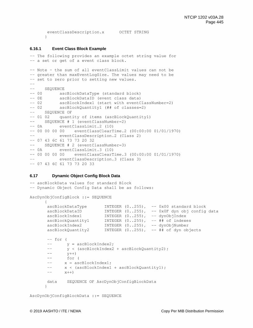
NTCIP 1202 v03A.28 Page 445
© 2019 AASHTO / ITE / NEMA Copy Per MIB Distribution Permission
eventClassDescription.x OCTET STRING }
6.16.1 Event Class Block Example -- The following provides an example octet string value for -- a set or get of a event class block. -- Note – the sum of all eventClassLimit values can not be -- greater than maxEventLogSize. The values may need to be -- set to zero prior to setting new values. -- -- SEQUENCE -- 00 ascBlockDataType (standard block) -- 0E ascBlockDataID (event class data) -- 02 ascBlockIndex1 (start with eventClassNumber=2) -- 02 ascBlockQuantity1 (## of classes=2) -- SEQUENCE OF -- 01 02 quantity of items (ascBlockQuantity1) -- SEQUENCE # 1 (eventClassNumber=2) -- 0A eventClassLimit.2 (10) -- 00 00 00 00 eventClassClearTime.2 (00:00:00 01/01/1970) -- eventClassDescription.2 (Class 2) -- 07 43 6C 61 73 73 20 32 -- SEQUENCE # 2 (eventClassNumber=3) -- 0A eventClassLimit.3 (10) -- 00 00 00 00 eventClassClearTime.3 (00:00:00 01/01/1970) -- eventClassDescription.3 (Class 3) -- 07 43 6C 61 73 73 20 33
6.17 Dynamic Object Config Block Data -- ascBlockData values for standard Block -- Dynamic Object Config Data shall be as follows: AscDynObjConfigBlock ::= SEQUENCE
{ ascBlockDataType INTEGER (0..255), -- 0x00 standard block ascBlockDataID INTEGER (0..255), -- 0x0F dyn obj config data ascBlockIndex1 INTEGER (0..255), -- dynObjIndex ascBlockQuantity1 INTEGER (0..255), -- ## of indexes ascBlockIndex2 INTEGER (0..255), -- dynObjNumber ascBlockQuantity2 INTEGER (0..255), -- ## of dyn objects -- for ( -- y = ascBlockIndex2; -- y < (ascBlockIndex2 + ascBlockQuantity2); -- y++) -- for ( -- x = ascBlockIndex1; -- x < (ascBlockIndex1 + ascBlockQuantity1); -- x++) data SEQUENCE OF AscDynObjConfigBlockData }
AscDynObjConfigBlockData ::= SEQUENCE
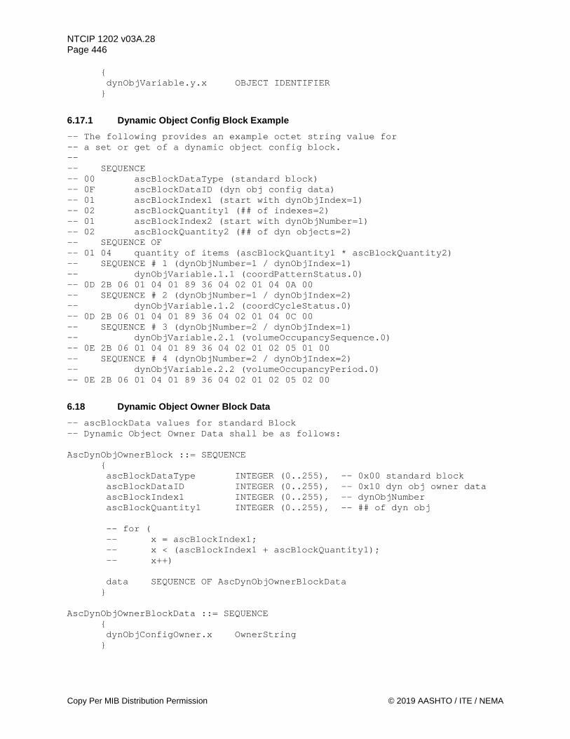
NTCIP 1202 v03A.28 Page 446
Copy Per MIB Distribution Permission © 2019 AASHTO / ITE / NEMA
{ dynObjVariable.y.x OBJECT IDENTIFIER }
6.17.1 Dynamic Object Config Block Example -- The following provides an example octet string value for -- a set or get of a dynamic object config block. -- -- SEQUENCE -- 00 ascBlockDataType (standard block) -- 0F ascBlockDataID (dyn obj config data) -- 01 ascBlockIndex1 (start with dynObjIndex=1) -- 02 ascBlockQuantity1 (## of indexes=2) -- 01 ascBlockIndex2 (start with dynObjNumber=1) -- 02 ascBlockQuantity2 (## of dyn objects=2) -- SEQUENCE OF -- 01 04 quantity of items (ascBlockQuantity1 * ascBlockQuantity2) -- SEQUENCE # 1 (dynObjNumber=1 / dynObjIndex=1) -- dynObjVariable.1.1 (coordPatternStatus.0) -- 0D 2B 06 01 04 01 89 36 04 02 01 04 0A 00 -- SEQUENCE # 2 (dynObjNumber=1 / dynObjIndex=2) -- dynObjVariable.1.2 (coordCycleStatus.0) -- 0D 2B 06 01 04 01 89 36 04 02 01 04 0C 00 -- SEQUENCE # 3 (dynObjNumber=2 / dynObjIndex=1) -- dynObjVariable.2.1 (volumeOccupancySequence.0) -- 0E 2B 06 01 04 01 89 36 04 02 01 02 05 01 00 -- SEQUENCE # 4 (dynObjNumber=2 / dynObjIndex=2) -- dynObjVariable.2.2 (volumeOccupancyPeriod.0) -- 0E 2B 06 01 04 01 89 36 04 02 01 02 05 02 00
6.18 Dynamic Object Owner Block Data -- ascBlockData values for standard Block -- Dynamic Object Owner Data shall be as follows: AscDynObjOwnerBlock ::= SEQUENCE
{ ascBlockDataType INTEGER (0..255), -- 0x00 standard block ascBlockDataID INTEGER (0..255), -- 0x10 dyn obj owner data ascBlockIndex1 INTEGER (0..255), -- dynObjNumber ascBlockQuantity1 INTEGER (0..255), -- ## of dyn obj -- for ( -- x = ascBlockIndex1; -- x < (ascBlockIndex1 + ascBlockQuantity1); -- x++) data SEQUENCE OF AscDynObjOwnerBlockData }
AscDynObjOwnerBlockData ::= SEQUENCE
{ dynObjConfigOwner.x OwnerString }

NTCIP 1202 v03A.28 Page 447
© 2019 AASHTO / ITE / NEMA Copy Per MIB Distribution Permission
6.18.1 Dynamic Object Owner Block Example -- The following provides an example octet string value for -- a set or get of a dynamic object owner block. -- -- SEQUENCE -- 00 ascBlockDataType (standard block) -- 10 ascBlockDataID (dyn obj owner data) -- 02 ascBlockIndex1 (start with dynObjNumber=2) -- 02 ascBlockQuantity1 (## of dyn obj=2) -- SEQUENCE OF -- 01 02 quantity of items (ascBlockQuantity1) -- SEQUENCE # 1 (dynObjNumber=2) -- dynObjConfigOwner.2 (TMC 2) -- 05 54 4D 43 20 32 -- SEQUENCE # 2 (dynObjNumber=3) -- dynObjConfigOwner.3 (TMC 2) -- 05 54 4D 43 20 32
6.19 Dynamic Object Status Block Data -- ascBlockData values for standard Block -- Dynamic Object Status Data shall be as follows: AscDynObjStatusBlock ::= SEQUENCE
{ ascBlockDataType INTEGER (0..255), -- 0x00 standard block ascBlockDataID INTEGER (0..255), -- 0x11 dyn obj status data ascBlockIndex1 INTEGER (0..255), -- dynObjNumber ascBlockQuantity1 INTEGER (0..255), -- ## of dyn obj -- for ( -- x = ascBlockIndex1; -- x < (ascBlockIndex1 + ascBlockQuantity1); -- x++) data SEQUENCE OF AscDynObjStatusBlockData }
AscDynObjStatusBlockData ::= SEQUENCE
{ dynObjConfigStatus.x ConfigEntryStatus }
6.19.1 Dynamic Object Status Block Example -- The following provides an example octet string value for -- a set or get of a dynamic object status block. -- -- SEQUENCE -- 00 ascBlockDataType (standard block) -- 11 ascBlockDataID (dyn obj status data) -- 02 ascBlockIndex1 (start with dynObjNumber=2) -- 02 ascBlockQuantity1 (## of dyn obj=2) -- SEQUENCE OF -- 01 02 quantity of items (ascBlockQuantity1) -- SEQUENCE # 1 (dynObjNumber=2)
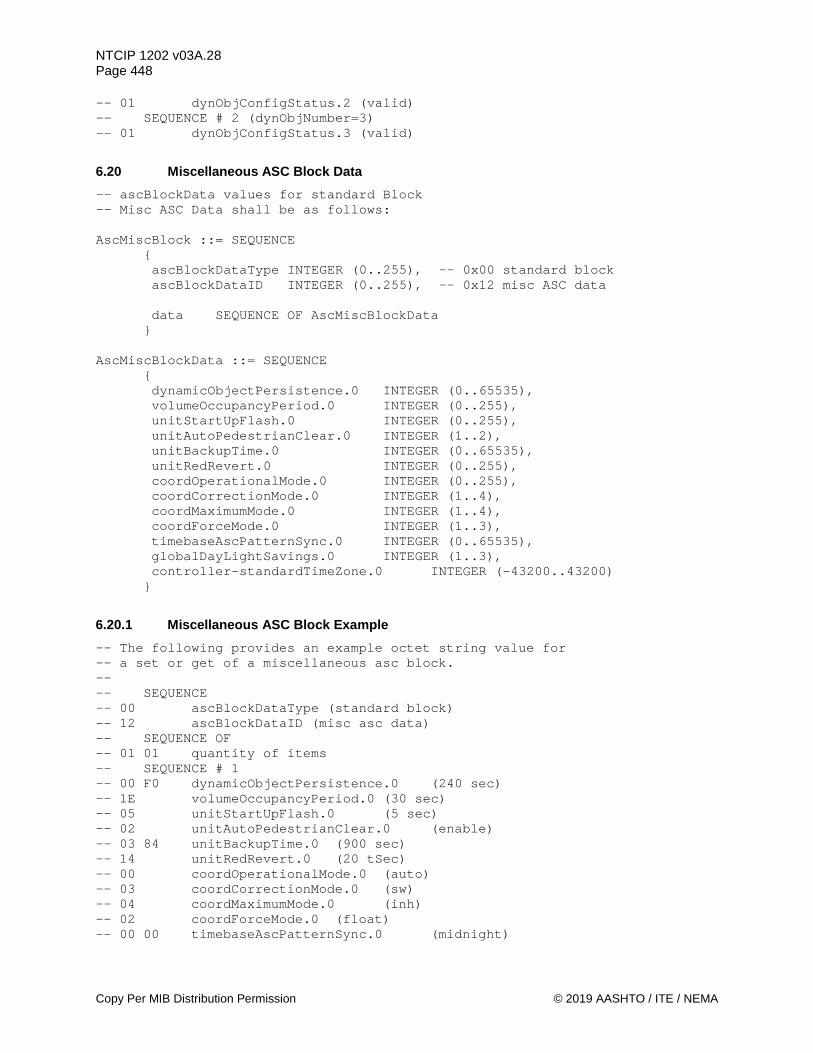
NTCIP 1202 v03A.28 Page 448
Copy Per MIB Distribution Permission © 2019 AASHTO / ITE / NEMA
-- 01 dynObjConfigStatus.2 (valid) -- SEQUENCE # 2 (dynObjNumber=3) -- 01 dynObjConfigStatus.3 (valid)
6.20 Miscellaneous ASC Block Data -- ascBlockData values for standard Block -- Misc ASC Data shall be as follows: AscMiscBlock ::= SEQUENCE
{ ascBlockDataType INTEGER (0..255), -- 0x00 standard block ascBlockDataID INTEGER (0..255), -- 0x12 misc ASC data data SEQUENCE OF AscMiscBlockData }
AscMiscBlockData ::= SEQUENCE
{ dynamicObjectPersistence.0 INTEGER (0..65535), volumeOccupancyPeriod.0 INTEGER (0..255), unitStartUpFlash.0 INTEGER (0..255), unitAutoPedestrianClear.0 INTEGER (1..2), unitBackupTime.0 INTEGER (0..65535), unitRedRevert.0 INTEGER (0..255), coordOperationalMode.0 INTEGER (0..255), coordCorrectionMode.0 INTEGER (1..4), coordMaximumMode.0 INTEGER (1..4), coordForceMode.0 INTEGER (1..3), timebaseAscPatternSync.0 INTEGER (0..65535), globalDayLightSavings.0 INTEGER (1..3), controller-standardTimeZone.0 INTEGER (-43200..43200) }
6.20.1 Miscellaneous ASC Block Example -- The following provides an example octet string value for -- a set or get of a miscellaneous asc block. -- -- SEQUENCE -- 00 ascBlockDataType (standard block) -- 12 ascBlockDataID (misc asc data) -- SEQUENCE OF -- 01 01 quantity of items -- SEQUENCE # 1 -- 00 F0 dynamicObjectPersistence.0 (240 sec) -- 1E volumeOccupancyPeriod.0 (30 sec) -- 05 unitStartUpFlash.0 (5 sec) -- 02 unitAutoPedestrianClear.0 (enable) -- 03 84 unitBackupTime.0 (900 sec) -- 14 unitRedRevert.0 (20 tSec) -- 00 coordOperationalMode.0 (auto) -- 03 coordCorrectionMode.0 (sw) -- 04 coordMaximumMode.0 (inh) -- 02 coordForceMode.0 (float) -- 00 00 timebaseAscPatternSync.0 (midnight)
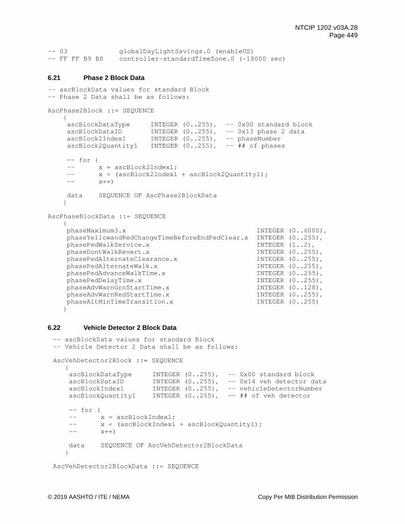
NTCIP 1202 v03A.28 Page 449
© 2019 AASHTO / ITE / NEMA Copy Per MIB Distribution Permission
-- 03 globalDayLightSavings.0 (enableUS) -- FF FF B9 B0 controller-standardTimeZone.0 (-18000 sec)
6.21 Phase 2 Block Data -- ascBlockData values for standard Block -- Phase 2 Data shall be as follows: AscPhase2Block ::= SEQUENCE
{ ascBlockDataType INTEGER (0..255), -- 0x00 standard block ascBlockDataID INTEGER (0..255), -- 0x13 phase 2 data ascBlock2Index1 INTEGER (0..255), -- phaseNumber ascBlock2Quantity1 INTEGER (0..255), -- ## of phases
-- for { -- x = ascBlock2Index1; -- x < (ascBlock2Index1 + ascBlock2Quantity1); -- x++)
data SEQUENCE OF AscPhase2BlockData
} AscPhaseBlockData ::= SEQUENCE
{ phaseMaximum3.x INTEGER (0..6000), phaseYellowandRedChangeTimeBeforeEndPedClear.x INTEGER (0..255), phasePedWalkService.x INTEGER (1..2), phaseDontWalkRevert.x INTEGER (0..255), phasePedAlternateClearance.x INTEGER (0..255), phasePedAlternateWalk.x INTEGER (0..255), phasePedAdvanceWalkTime.x INTEGER (0..255), phasePedDelayTime.x INTEGER (0..255), phaseAdvWarnGrnStartTime.x INTEGER (0..128), phaseAdvWarnRedStartTime.x INTEGER (0..255), phaseAltMinTimeTransition.x INTEGER (0..255)
}
6.22 Vehicle Detector 2 Block Data -- ascBlockData values for standard Block -- Vehicle Detector 2 Data shall be as follows:
AscVehDetector2Block ::= SEQUENCE
{ ascBlockDataType INTEGER (0..255), -- 0x00 standard block ascBlockDataID INTEGER (0..255), -- 0x14 veh detector data ascBlockIndex1 INTEGER (0..255), -- vehicleDetectorNumber ascBlockQuantity1 INTEGER (0..255), -- ## of veh detector
-- for ( -- x = ascBlockIndex1; -- x < (ascBlockIndex1 + ascBlockQuantity1); -- x++)
data SEQUENCE OF AscVehDetector2BlockData
} AscVehDetector2BlockData ::= SEQUENCE
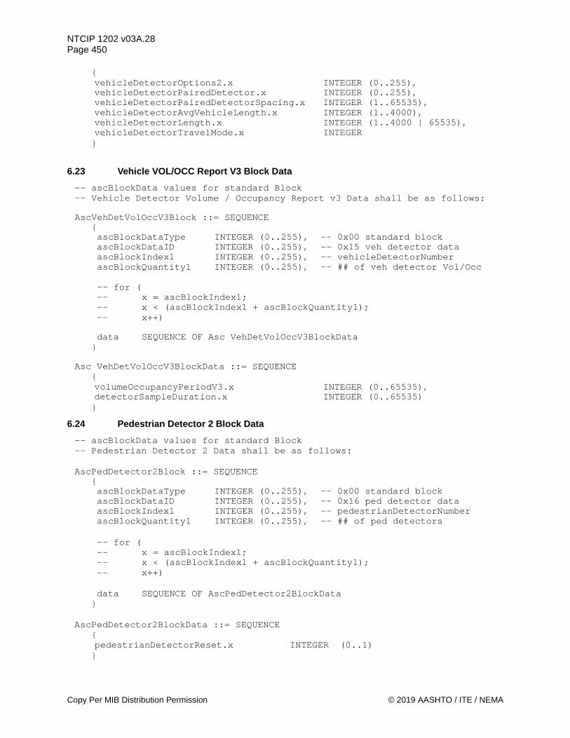
NTCIP 1202 v03A.28 Page 450
Copy Per MIB Distribution Permission © 2019 AASHTO / ITE / NEMA
{
vehicleDetectorOptions2.x INTEGER (0..255), vehicleDetectorPairedDetector.x INTEGER (0..255), vehicleDetectorPairedDetectorSpacing.x INTEGER (1..65535), vehicleDetectorAvgVehicleLength.x INTEGER (1..4000), vehicleDetectorLength.x INTEGER (1..4000 | 65535), vehicleDetectorTravelMode.x INTEGER }
6.23 Vehicle VOL/OCC Report V3 Block Data -- ascBlockData values for standard Block -- Vehicle Detector Volume / Occupancy Report v3 Data shall be as follows:
AscVehDetVolOccV3Block ::= SEQUENCE
{ ascBlockDataType INTEGER (0..255), -- 0x00 standard block ascBlockDataID INTEGER (0..255), -- 0x15 veh detector data ascBlockIndex1 INTEGER (0..255), -- vehicleDetectorNumber ascBlockQuantity1 INTEGER (0..255), -- ## of veh detector Vol/Occ
-- for ( -- x = ascBlockIndex1; -- x < (ascBlockIndex1 + ascBlockQuantity1); -- x++)
data SEQUENCE OF Asc VehDetVolOccV3BlockData
} Asc VehDetVolOccV3BlockData ::= SEQUENCE
{
volumeOccupancyPeriodV3.x INTEGER (0..65535), detectorSampleDuration.x INTEGER (0..65535) }
6.24 Pedestrian Detector 2 Block Data -- ascBlockData values for standard Block -- Pedestrian Detector 2 Data shall be as follows:
AscPedDetector2Block ::= SEQUENCE
{ ascBlockDataType INTEGER (0..255), -- 0x00 standard block ascBlockDataID INTEGER (0..255), -- 0x16 ped detector data ascBlockIndex1 INTEGER (0..255), -- pedestrianDetectorNumber ascBlockQuantity1 INTEGER (0..255), -- ## of ped detectors
-- for ( -- x = ascBlockIndex1; -- x < (ascBlockIndex1 + ascBlockQuantity1); -- x++)
data SEQUENCE OF AscPedDetector2BlockData
} AscPedDetector2BlockData ::= SEQUENCE
{ pedestrianDetectorReset.x INTEGER (0..1) }
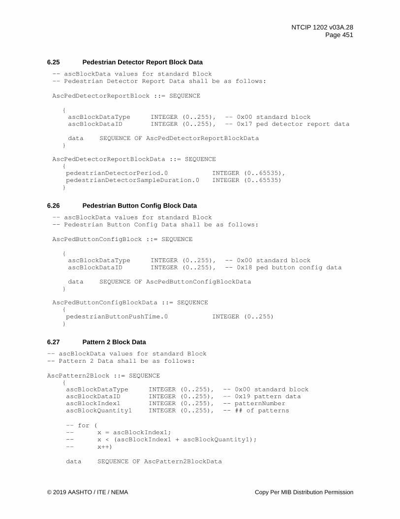
NTCIP 1202 v03A.28 Page 451
© 2019 AASHTO / ITE / NEMA Copy Per MIB Distribution Permission
6.25 Pedestrian Detector Report Block Data -- ascBlockData values for standard Block -- Pedestrian Detector Report Data shall be as follows:
AscPedDetectorReportBlock ::= SEQUENCE
{ ascBlockDataType INTEGER (0..255), -- 0x00 standard block ascBlockDataID INTEGER (0..255), -- 0x17 ped detector report data
data SEQUENCE OF AscPedDetectorReportBlockData
} AscPedDetectorReportBlockData ::= SEQUENCE
{ pedestrianDetectorPeriod.0 INTEGER (0..65535), pedestrianDetectorSampleDuration.0 INTEGER (0..65535)
}
6.26 Pedestrian Button Config Block Data -- ascBlockData values for standard Block -- Pedestrian Button Config Data shall be as follows:
AscPedButtonConfigBlock ::= SEQUENCE
{ ascBlockDataType INTEGER (0..255), -- 0x00 standard block ascBlockDataID INTEGER (0..255), -- 0x18 ped button config data
data SEQUENCE OF AscPedButtonConfigBlockData
} AscPedButtonConfigBlockData ::= SEQUENCE
{ pedestrianButtonPushTime.0 INTEGER (0..255)
}
6.27 Pattern 2 Block Data -- ascBlockData values for standard Block -- Pattern 2 Data shall be as follows: AscPattern2Block ::= SEQUENCE
{ ascBlockDataType INTEGER (0..255), -- 0x00 standard block ascBlockDataID INTEGER (0..255), -- 0x19 pattern data ascBlockIndex1 INTEGER (0..255), -- patternNumber ascBlockQuantity1 INTEGER (0..255), -- ## of patterns
-- for ( -- x = ascBlockIndex1; -- x < (ascBlockIndex1 + ascBlockQuantity1); -- x++)
data SEQUENCE OF AscPattern2BlockData

NTCIP 1202 v03A.28 Page 452
Copy Per MIB Distribution Permission © 2019 AASHTO / ITE / NEMA
} AscPattern2BlockData ::= SEQUENCE
{ patternCoordSyncPoint.x INTEGER, patternOptions.x INTEGER (1..255), patternSpatEnabledLanes.x OCTET STRING }
6.28 Split 2 Block Data -- ascBlockData values for standard Block -- Split 2 Data shall be as follows: AscSplit2Block ::= SEQUENCE
{ ascBlockDataType INTEGER (0..255), -- 0x00 standard block ascBlockDataID INTEGER (0..255), -- 0x1A split 2 data ascBlockIndex1 INTEGER (0..255), -- splitPhase ascBlockQuantity1 INTEGER (0..255), -- ## of phases ascBlockIndex2 INTEGER (0..255), -- splitNumber ascBlockQuantity2 INTEGER (0..255), -- ## of splits
-- for ( -- y = ascBlockIndex2; -- y < (ascBlockIndex2 + ascBlockQuantity2); -- y++) -- for ( -- x = ascBlockIndex1; -- x < (ascBlockIndex1 + ascBlockQuantity1); -- x++) data SEQUENCE OF AscSplit2BlockData
} AscSplitBlockData ::= SEQUENCE
{ splitOptions.y.x INTEGER (0..255) }
6.29 Preempt 2 Block Data -- ascBlockData values for standard Block -- Preempt 2 Data shall be as follows: AscPreempt2Block ::= SEQUENCE
{ ascBlockDataType INTEGER (0..255), -- 0x00 standard block ascBlockDataID INTEGER (0..255), -- 0x1B preempt data ascBlockIndex1 INTEGER (0..255), -- preemptNumber ascBlockQuantity1 INTEGER (0..255), -- ## of preempts
-- for ( -- x = ascBlockIndex1; -- x < (ascBlockIndex1 + ascBlockQuantity1); -- x++)
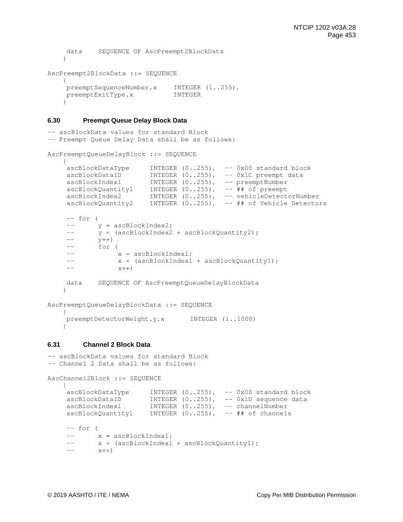
NTCIP 1202 v03A.28 Page 453
© 2019 AASHTO / ITE / NEMA Copy Per MIB Distribution Permission
data SEQUENCE OF AscPreempt2BlockData }
AscPreempt2BlockData ::= SEQUENCE
{ preemptSequenceNumber.x INTEGER (1..255), preemptExitType.x INTEGER
}
6.30 Preempt Queue Delay Block Data -- ascBlockData values for standard Block -- Preempt Queue Delay Data shall be as follows: AscPreemptQueueDelayBlock ::= SEQUENCE
{ ascBlockDataType INTEGER (0..255), -- 0x00 standard block ascBlockDataID INTEGER (0..255), -- 0x1C preempt data ascBlockIndex1 INTEGER (0..255), -- preemptNumber ascBlockQuantity1 INTEGER (0..255), -- ## of preempt ascBlockIndex2 INTEGER (0..255), -- vehicleDetectorNumber ascBlockQuantity2 INTEGER (0..255), -- ## of Vehicle Detectors
-- for ( -- y = ascBlockIndex2; -- y < (ascBlockIndex2 + ascBlockQuantity2); -- y++) -- for ( -- x = ascBlockIndex1; -- x < (ascBlockIndex1 + ascBlockQuantity1); -- x++) data SEQUENCE OF AscPreemptQueueDelayBlockData
} AscPreemptQueueDelayBlockData ::= SEQUENCE
{ preemptDetectorWeight.y.x INTEGER (1..1000)
}
6.31 Channel 2 Block Data -- ascBlockData values for standard Block -- Channel 2 Data shall be as follows: AscChannel2Block ::= SEQUENCE
{ ascBlockDataType INTEGER (0..255), -- 0x00 standard block ascBlockDataID INTEGER (0..255), -- 0x1D sequence data ascBlockIndex1 INTEGER (0..255), -- channelNumber ascBlockQuantity1 INTEGER (0..255), -- ## of channels
-- for ( -- x = ascBlockIndex1; -- x < (ascBlockIndex1 + ascBlockQuantity1); -- x++)

NTCIP 1202 v03A.28 Page 454
Copy Per MIB Distribution Permission © 2019 AASHTO / ITE / NEMA
data SEQUENCE OF AscChannel2BlockData }
AscChannel2BlockData ::= SEQUENCE
{ channelGreenType.x INTEGER (0..255), channelGreenIncluded.x OCTET STRING, channelIntersectionId.x INTEGER (0..65535)
}
6.32 Overlap 2 Block Data -- ascBlockData values for standard Block -- Overlap 2 Data shall be as follows: AscOverlap2Block ::= SEQUENCE
{ ascBlockDataType INTEGER (0..255), -- 0x00 standard block ascBlockDataID INTEGER (0..255), -- 0x1E overlap data ascBlockIndex1 INTEGER (0..255), -- overlapNumber ascBlockQuantity1 INTEGER (0..255), -- ## of overlaps
-- for ( -- x = ascBlockIndex1; -- x < (ascBlockIndex1 + ascBlockQuantity1); -- x++)
data SEQUENCE OF AscOverlap2BlockData
} AscOverlap2BlockData ::= SEQUENCE
{ overlapWalk.x INTEGER (0..255), overlapPedClearance.x INTEGER (0..255), overlapConflictingPedPhases OCTET STRING
}
6.33 Communications Port Definition Block Data -- ascBlockData values for standard Block -- Communications Port Definition Data shall be as follows: AscCommPortDefBlock ::= SEQUENCE
{ ascBlockDataType INTEGER (0..255), -- 0x00 standard block ascBlockDataID INTEGER (0..255), -- 0x1F comm port def data ascBlockIndex1 INTEGER (1..255), -- ifIndex ascBlockQuantity1 INTEGER (1..255), -- ## of Comm Port
-- for ( -- x = ascBlockIndex1; -- x < (ascBlockIndex1 + ascBlockQuantity1); -- x++)
data SEQUENCE OF AscCommPortDefBlockData
} AscCommPortDefBlockData ::= SEQUENCE
{
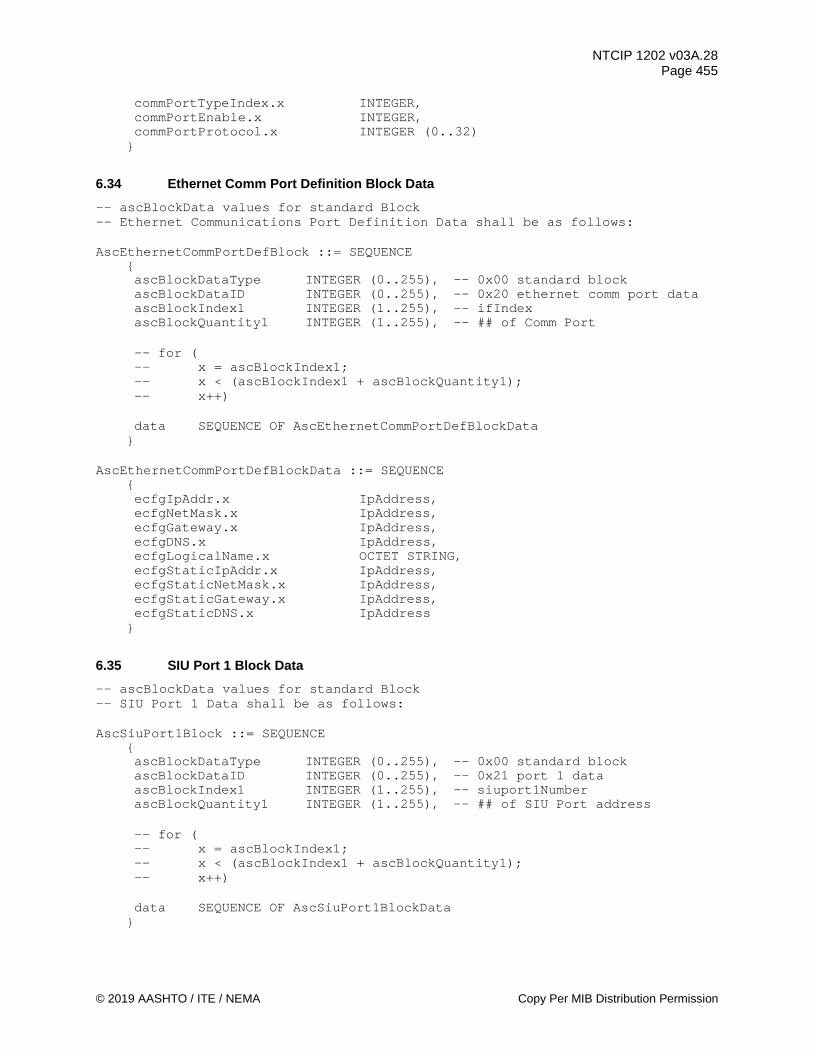
NTCIP 1202 v03A.28 Page 455
© 2019 AASHTO / ITE / NEMA Copy Per MIB Distribution Permission
commPortTypeIndex.x INTEGER, commPortEnable.x INTEGER, commPortProtocol.x INTEGER (0..32)
}
6.34 Ethernet Comm Port Definition Block Data -- ascBlockData values for standard Block -- Ethernet Communications Port Definition Data shall be as follows: AscEthernetCommPortDefBlock ::= SEQUENCE
{ ascBlockDataType INTEGER (0..255), -- 0x00 standard block ascBlockDataID INTEGER (0..255), -- 0x20 ethernet comm port data ascBlockIndex1 INTEGER (1..255), -- ifIndex ascBlockQuantity1 INTEGER (1..255), -- ## of Comm Port
-- for ( -- x = ascBlockIndex1; -- x < (ascBlockIndex1 + ascBlockQuantity1); -- x++)
data SEQUENCE OF AscEthernetCommPortDefBlockData
} AscEthernetCommPortDefBlockData ::= SEQUENCE
{ ecfgIpAddr.x IpAddress, ecfgNetMask.x IpAddress, ecfgGateway.x IpAddress, ecfgDNS.x IpAddress, ecfgLogicalName.x OCTET STRING, ecfgStaticIpAddr.x IpAddress, ecfgStaticNetMask.x IpAddress, ecfgStaticGateway.x IpAddress, ecfgStaticDNS.x IpAddress
}
6.35 SIU Port 1 Block Data -- ascBlockData values for standard Block -- SIU Port 1 Data shall be as follows: AscSiuPort1Block ::= SEQUENCE
{ ascBlockDataType INTEGER (0..255), -- 0x00 standard block ascBlockDataID INTEGER (0..255), -- 0x21 port 1 data ascBlockIndex1 INTEGER (1..255), -- siuport1Number ascBlockQuantity1 INTEGER (1..255), -- ## of SIU Port address
-- for ( -- x = ascBlockIndex1; -- x < (ascBlockIndex1 + ascBlockQuantity1); -- x++)
data SEQUENCE OF AscSiuPort1BlockData
}

NTCIP 1202 v03A.28 Page 456
Copy Per MIB Distribution Permission © 2019 AASHTO / ITE / NEMA
AscSiuPort1BlockData ::= SEQUENCE { siuport1DevicePresent.x INTEGER (0..1)
}
6.36 Miscellaneous 2 ASC Block Data -- ascBlockData values for standard Block -- Miscellaneous ASC 2 Data shall be as follows: AscMisc2Block ::= SEQUENCE
{ ascBlockDataType INTEGER (0..255), -- 0x00 standard block ascBlockDataID INTEGER (0..255), -- 0x22 misc ASC 2 data
data SEQUENCE OF AscMisc2BlockData
} AscMisc2BlockData ::= SEQUENCE
{ unitStartUpFlashMode.0 INTEGER, unitUserDefinedBackupTime.0 INTEGER (0..16777216), unitCoordSyncPoint.0 INTEGER, unitMCETimeout.0 INTEGER (0..255), unitMCEIntAdv.0 INTEGER (0..1), eventLogConfigPersistence.0 INTEGER (0..65535), eventLogPersistence.0 INTEGER (0..65535)
}
6.37 User-Defined Backup Timer Definition Block Data -- ascBlockData values for standard Block -- User-Defined Backup Timer Data shall be as follows: AscUserDefinedBackupTimerBlock ::= SEQUENCE { ascBlockDataType INTEGER (0..255), -- 0x00 standard block ascBlockDataID INTEGER (0..255), -- 0x23 user-def backup timer data ascBlockIndex1 INTEGER (1..65535), -- unitUserDefinedBackupTimeContentNumber ascBlockQuantity1 INTEGER (1..65535), -- ## of OIDs in User-Def Timer data SEQUENCE OF AscUserDefinedBackupTimerBlockData }
AscUserDefinedBackupTimerBlockData ::= SEQUENCE
{ unitUserDefinedBackupTimeContentOID.x OBJECT IDENTIFIER, unitUserDefinedBackupTimeContentDescription.x OCTET STRING
}
6.38 ASC Location Block Data -- ascBlockData values for standard Block -- ASC Location Data shall be as follows: AscLocationBlock ::= SEQUENCE
{ ascBlockDataType INTEGER (0..255), -- 0x00 standard block
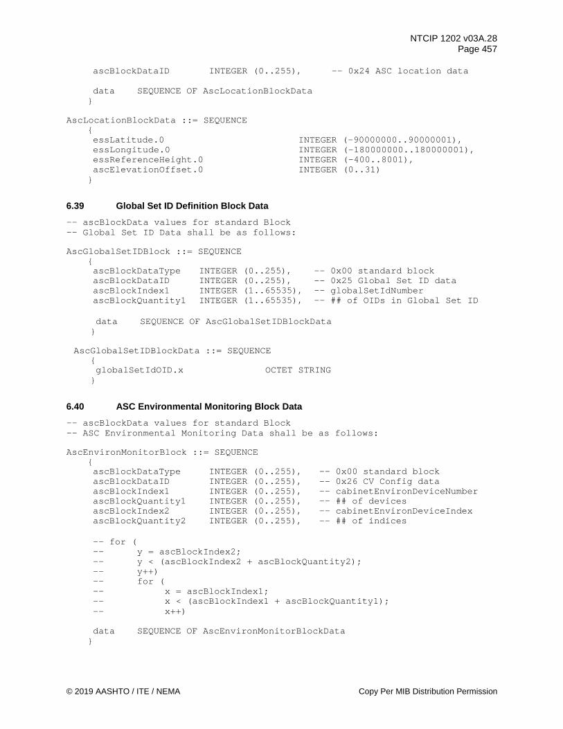
NTCIP 1202 v03A.28 Page 457
© 2019 AASHTO / ITE / NEMA Copy Per MIB Distribution Permission
ascBlockDataID INTEGER (0..255), -- 0x24 ASC location data
data SEQUENCE OF AscLocationBlockData }
AscLocationBlockData ::= SEQUENCE
{ essLatitude.0 INTEGER (-90000000..90000001), essLongitude.0 INTEGER (-180000000..180000001), essReferenceHeight.0 INTEGER (-400..8001), ascElevationOffset.0 INTEGER (0..31)
}
6.39 Global Set ID Definition Block Data -- ascBlockData values for standard Block -- Global Set ID Data shall be as follows: AscGlobalSetIDBlock ::= SEQUENCE
{ ascBlockDataType INTEGER (0..255), -- 0x00 standard block ascBlockDataID INTEGER (0..255), -- 0x25 Global Set ID data ascBlockIndex1 INTEGER (1..65535), -- globalSetIdNumber ascBlockQuantity1 INTEGER (1..65535), -- ## of OIDs in Global Set ID
data SEQUENCE OF AscGlobalSetIDBlockData
} AscGlobalSetIDBlockData ::= SEQUENCE
{ globalSetIdOID.x OCTET STRING
}
6.40 ASC Environmental Monitoring Block Data -- ascBlockData values for standard Block -- ASC Environmental Monitoring Data shall be as follows: AscEnvironMonitorBlock ::= SEQUENCE
{ ascBlockDataType INTEGER (0..255), -- 0x00 standard block ascBlockDataID INTEGER (0..255), -- 0x26 CV Config data ascBlockIndex1 INTEGER (0..255), -- cabinetEnvironDeviceNumber ascBlockQuantity1 INTEGER (0..255), -- ## of devices ascBlockIndex2 INTEGER (0..255), -- cabinetEnvironDeviceIndex ascBlockQuantity2 INTEGER (0..255), -- ## of indices
-- for ( -- y = ascBlockIndex2; -- y < (ascBlockIndex2 + ascBlockQuantity2); -- y++) -- for ( -- x = ascBlockIndex1; -- x < (ascBlockIndex1 + ascBlockQuantity1); -- x++)
data SEQUENCE OF AscEnvironMonitorBlockData
}

NTCIP 1202 v03A.28 Page 458
Copy Per MIB Distribution Permission © 2019 AASHTO / ITE / NEMA
AscEnvironMonitorBlockData ::= SEQUENCE { cabinetEnvironDeviceType.y.x INTEGER, cabinetEnvironDeviceDescription.y.x DisplayString (SIZE (0..64))
}
6.41 ASC Cabinet Temperature Sensor Block Data -- ascBlockData values for standard Block -- ASC Cabinet Temperature Sensor Data shall be as follows: AscCabinetTemperatureSensorBlock ::= SEQUENCE
{ ascBlockDataType INTEGER (0..255), -- 0x00 standard block ascBlockDataID INTEGER (0..255), -- 0x27 Cabinet Temp Sensor data ascBlockIndex1 INTEGER (0..255), -- cabinetTempSensorIndex ascBlockQuantity1 INTEGER (0..255), -- ## of devices
-- for ( -- x = ascBlockIndex1; -- x < (ascBlockIndex1 + ascBlockQuantity1); -- x++)
data SEQUENCE OF AscCabinetTemperatureSensorBlockData
} AscCabinetTemperatureSensorBlockData ::= SEQUENCE
{ cabinetTempSensorDescription.x DisplayString (SIZE (0..64)), cabinetTempSensorHighThreshold.x INTEGER (-128..127), cabinetTempSensorLowThreshold.x INTEGER (-128..127)
}
6.42 ASC Cabinet Humidity Sensor Block Data -- ascBlockData values for standard Block -- ASC Cabinet Humidity Sensor Data shall be as follows: AscCabinetHumiditySensorBlock ::= SEQUENCE
{ ascBlockDataType INTEGER (0..255), -- 0x00 standard block ascBlockDataID INTEGER (0..255), -- 0x28 cabinet humidity data ascBlockIndex1 INTEGER (0..255), -- cabinetHumiditySensorIndex ascBlockQuantity1 INTEGER (0..255), -- ## of devices
-- for ( -- x = ascBlockIndex1; -- x < (ascBlockIndex1 + ascBlockQuantity1); -- x++)
data SEQUENCE OF AscCabinetHumiditySensorBlockData
} AscCabinetHumiditySensorBlockData ::= SEQUENCE
{ cabinetHumiditySensorDescription.x DisplayString (SIZE (0..64)), cabinetHumidityThreshold.x INTEGER (0..101)
}

NTCIP 1202 v03A.28 Page 459
© 2019 AASHTO / ITE / NEMA Copy Per MIB Distribution Permission
6.43 ASC I/O Input Mapping Block Data -- ascBlockData values for standard Block -- ASC I/O Input Mapping Data shall be as follows: AscIOinputMapBlock ::= SEQUENCE
{ ascBlockDataType INTEGER (0..255), -- 0x00 standard block ascBlockDataID INTEGER (0..255), -- 0x29 ASC I/O Mapping data ascBlockIndex1 INTEGER (0..255), -- ascIOmapNumber ascBlockQuantity1 INTEGER (0..255), -- ## of I/O maps ascBlockIndex2 INTEGER (0..65535), -- ascIOinputMapIOindex ascBlockQuantity2 INTEGER (0..65535), -- ## of indices
data SEQUENCE OF AscIOinputMapBlockData
}
-- for ( -- z = ascBlockIndex2; -- z < (ascBlockIndex2 + ascBlockQuantity2); -- z++) -- for ( -- y = ascBlockIndex1; -- y < (ascBlockIndex1 + ascBlockQuantity1); -- y++) data SEQUENCE OF AscIOMapConfigBlockData
} AscIOMapConfigBlockData::= SEQUENCE
{ ascIOinputMapDeviceType INTEGER (0..255), -- Device Type ascIOinputMapDevicePNN INTEGER (0..65535),-- NEMA PNN for custom ascIOinputMapDevicePtype INTEGER (0..255), -- Custom device type ascIOinputMapDeviceAddr INTEGER (0..255), -- Device addr ascIOinputMapDevicePin INTEGER (0..255), -- device I/O pin index ascIOinputMapFuncType INTEGER (0..255), -- 0 or nemaPrivate code ascIOinputMapFuncPtype INTEGER (0..255), -- Custom function type set ascIOinputMapFunction INTEGER (0..255), -- function ascIOinputMapFuncIndex INTEGER (0..255) -- function index }
6.44 ASC I/O Input Status Block Data -- ascBlockData values for standard Block -- ASC I/O Input Status Data shall be as follows: AscIOinputStatusBlock ::= SEQUENCE
{ ascBlockDataType INTEGER (0..255), -- 0x00 standard block ascBlockDataID INTEGER (0..255), -- 0x2A ASC I/O Mapping data ascBlockIndex1 INTEGER (0..255), -- ascIOmapNumber ascBlockQuantity1 INTEGER (0..255), -- ## of I/O maps ascBlockIndex2 INTEGER (0..65535), -- ascIOinputMapIOindex ascBlockQuantity2 INTEGER (0..65535), -- ## of indices
data SEQUENCE OF AscIOinputStatusBlockData
}

NTCIP 1202 v03A.28 Page 460
Copy Per MIB Distribution Permission © 2019 AASHTO / ITE / NEMA
-- for ( -- z = ascBlockIndex2; -- z < (ascBlockIndex2 + ascBlockQuantity2); -- z++) -- for ( -- y = ascBlockIndex1; -- y < (ascBlockIndex1 + ascBlockQuantity1); -- y++) data SEQUENCE OF AscIOinputStatusBlockData
} AscIOinputStatusBlockData::= SEQUENCE
{ ascIOinputMapDevPinDescr OCTET STRING (0..32), -- Device Pin Description ascIOinputMapDevPinStatus INTEGER (0..1) -- Device Pin Status }
6.45 ASC I/O Output Mapping Block Data -- ascBlockData values for standard Block -- ASC I/O Output Mapping Data shall be as follows: AscIOoutputMapBlock ::= SEQUENCE
{ ascBlockDataType INTEGER (0..255), -- 0x00 standard block ascBlockDataID INTEGER (0..255), -- 0x2B ASC I/O Mapping data ascBlockIndex1 INTEGER (0..255), -- ascIOmapNumber ascBlockQuantity1 INTEGER (0..255), -- ## of I/O maps ascBlockIndex2 INTEGER (0..65535), -- ascIOoutputMapIOindex ascBlockQuantity2 INTEGER (0..65535), -- ## of indices
data SEQUENCE OF AscIOoutputMapBlockData
}
-- for ( -- z = ascBlockIndex2; -- z < (ascBlockIndex2 + ascBlockQuantity2); -- z++) -- for ( -- y = ascBlockIndex1; -- y < (ascBlockIndex1 + ascBlockQuantity1); -- y++) data SEQUENCE OF AscIOMapConfigBlockData
} AscIOoutputMapBlockData::= SEQUENCE
{ ascIOoutputMapDeviceType INTEGER (0..255), -- Device Type ascIOoutputMapDevicePNN INTEGER (0..65535),-- NEMA PNN for custom ascIOoutputMapDevicePtype INTEGER (0..255), -- Custom device type ascIOoutputMapDeviceAddr INTEGER (0..255), -- Device addr ascIOoutputMapDevicePin INTEGER (0..255), -- device I/O pin index ascIOoutputMapFuncType INTEGER (0..255), -- 0 or nemaPrivate code ascIOoutputMapFuncPtype INTEGER (0..255), -- Custom function type set ascIOoutputMapFunction INTEGER (0..255), -- function ascIOoutputMapFuncIndex INTEGER (0..255) -- function index
}
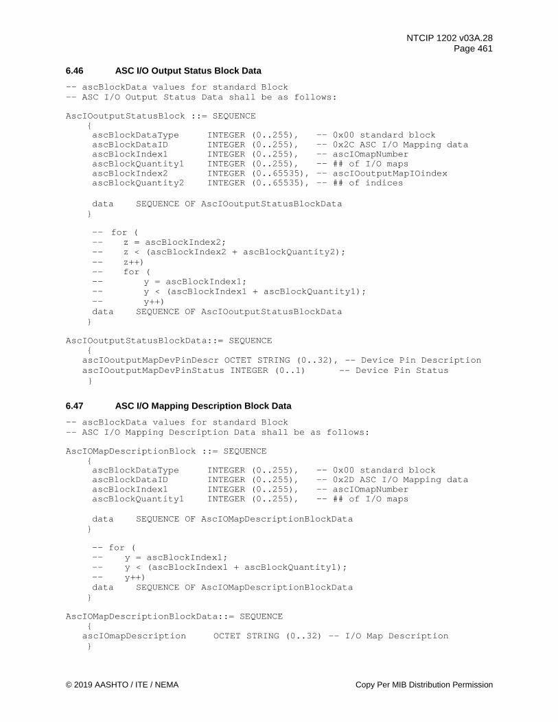
NTCIP 1202 v03A.28 Page 461
© 2019 AASHTO / ITE / NEMA Copy Per MIB Distribution Permission
6.46 ASC I/O Output Status Block Data -- ascBlockData values for standard Block -- ASC I/O Output Status Data shall be as follows: AscIOoutputStatusBlock ::= SEQUENCE
{ ascBlockDataType INTEGER (0..255), -- 0x00 standard block ascBlockDataID INTEGER (0..255), -- 0x2C ASC I/O Mapping data ascBlockIndex1 INTEGER (0..255), -- ascIOmapNumber ascBlockQuantity1 INTEGER (0..255), -- ## of I/O maps ascBlockIndex2 INTEGER (0..65535), -- ascIOoutputMapIOindex ascBlockQuantity2 INTEGER (0..65535), -- ## of indices
data SEQUENCE OF AscIOoutputStatusBlockData
}
-- for ( -- z = ascBlockIndex2; -- z < (ascBlockIndex2 + ascBlockQuantity2); -- z++) -- for ( -- y = ascBlockIndex1; -- y < (ascBlockIndex1 + ascBlockQuantity1); -- y++) data SEQUENCE OF AscIOoutputStatusBlockData
} AscIOoutputStatusBlockData::= SEQUENCE
{ ascIOoutputMapDevPinDescr OCTET STRING (0..32), -- Device Pin Description ascIOoutputMapDevPinStatus INTEGER (0..1) -- Device Pin Status }
6.47 ASC I/O Mapping Description Block Data -- ascBlockData values for standard Block -- ASC I/O Mapping Description Data shall be as follows: AscIOMapDescriptionBlock ::= SEQUENCE
{ ascBlockDataType INTEGER (0..255), -- 0x00 standard block ascBlockDataID INTEGER (0..255), -- 0x2D ASC I/O Mapping data ascBlockIndex1 INTEGER (0..255), -- ascIOmapNumber ascBlockQuantity1 INTEGER (0..255), -- ## of I/O maps data SEQUENCE OF AscIOMapDescriptionBlockData
}
-- for ( -- y = ascBlockIndex1; -- y < (ascBlockIndex1 + ascBlockQuantity1); -- y++) data SEQUENCE OF AscIOMapDescriptionBlockData
} AscIOMapDescriptionBlockData::= SEQUENCE
{ ascIOmapDescription OCTET STRING (0..32) -- I/O Map Description
}

NTCIP 1202 v03A.28 Page 462
Copy Per MIB Distribution Permission © 2019 AASHTO / ITE / NEMA
6.48 CV Configuration ASC Block Data -- ascBlockData values for standard Block -- Connected Vehicles Configuration Data shall be as follows: AscCvConfigBlock ::= SEQUENCE
{ ascBlockDataType INTEGER (0..255), -- 0x00 standard block ascBlockDataID INTEGER (0..255), -- 0x2E CV Config data
data SEQUENCE OF AscCvConfigBlockData
} AscCvConfigBlockData ::= SEQUENCE
{ rsuCommPort.0 INTEGER (0..255), spatEnabledLanesCommand.0 OCTET STRING, spatOptions.0 INTEGER(0..255), cvDetectionActuationSamplePeriod,0 INTEGER (1..65535), detectionReportCollection.0 INTEGER (0..255), spatStatus.0 INTEGER (0..16)
}
6.49 CV Logical RSU Ports Configuration Block Data -- ascBlockData values for standard Block -- Connected Vehicle RSU Ports Configuration Data shall be as follows: AscCvRsuPortConfigBlock ::= SEQUENCE
{ ascBlockDataType INTEGER (0..255), -- 0x00 standard block ascBlockDataID INTEGER (0..255), -- 0x2F CV RSU Port Config data ascBlockIndex1 INTEGER (1..255), -- rsuPortIndex ascBlockQuantity1 INTEGER (1..255), -- ## of CV RSU Port
data SEQUENCE OF AscCvRsuPortConfigBlockData
} AscCvRsuPortConfigBlockData ::= SEQUENCE
{ rsuPortPointer.x INTEGER (1..255), rsuPortName.x DisplayString (SIZE (0..255)), rsuPortPollingPeriod.x INTEGER (0..65535), rsuPortWatchdogTime.x INTEGER (0..65535), rsuPortNumber INTEGER (0..65535)
}
6.50 CV SPaT Enabled Lanes Concurrency Configuration Block Data -- ascBlockData values for standard Block -- Connected Vehicle SPaT-Enabled Lanes Concurrency Configuration Data -- shall be as follows: AscCvSpatLanesConcurrencyConfigBlock ::= SEQUENCE
{ ascBlockDataType INTEGER (0..255), -- 0x00 standard block ascBlockDataID INTEGER (0..255), -- 0x30 CV SPAT Lanes Concur data

NTCIP 1202 v03A.28 Page 463
© 2019 AASHTO / ITE / NEMA Copy Per MIB Distribution Permission
ascBlockIndex1 INTEGER (1..254), -- enabledLaneIndex ascBlockQuantity1 INTEGER (1..254), -- ## of MAP Lane
data SEQUENCE OF AscCvSpatLanesConcurrencyConfigBlockData
} AscCvSpatLanesConcurrencyConfigBlockData ::= SEQUENCE
{ enabledLaneConcurrency.x OCTET STRING
}
6.51 CV SPaT RSU Ports Configuration Block Data -- ascBlockData values for standard Block -- Connected Vehicle SPaT RSU Port Configuration Data shall be as follows: AscCvSpatRsuConfigBlock ::= SEQUENCE
{ ascBlockDataType INTEGER (0..255), -- 0x00 standard block ascBlockDataID INTEGER (0..255), -- 0x31 CV SPAT RSU Port data ascBlockIndex1 INTEGER (1..255), -- rsuPortIndex ascBlockQuantity1 INTEGER (1..255), -- ## of SPaT RSU Port
data SEQUENCE OF AscCvSpatRsuConfigBlockData
} AscCvSpatRsuConfigBlockData ::= SEQUENCE
{ spatPortOptions.x INTEGER (0..255), spatPortMapActivationCode.x MapActivationCode
}
6.52 CV Detector Configuration Block Data -- ascBlockData values for standard Block -- Connected Vehicle Detector Configuration Data shall be as follows: AscCvDetectorConfigBlock ::= SEQUENCE
{ ascBlockDataType INTEGER (0..255), -- 0x00 standard block ascBlockDataID INTEGER (0..255), -- 0x32 CV Detector Config data ascBlockIndex1 INTEGER (1..255), -- cvDetectorNumber ascBlockQuantity1 INTEGER (1..255), -- ## of CV Detector
data SEQUENCE OF AscCvDetectorConfigBlockData
} AscCvDetectorConfigBlockData ::= SEQUENCE
{ cvDetectorOptions.x INTEGER (0..255), cvDetectorIntersection.x INTEGER (1..65535), cvDetectorInput.x OCTET STRING, cvDetectorAssignment.x OCTET STRING, cvDetectorSamplePeriod.x INTEGER (0..255), cvDetectorUserClass.x INTEGER (0..255), cvDetectorHeading.x , -- see J2735-2016 DE_HeadingSlice cvDetectorMinSpeed.x INTEGER (0..8191), cvDetectorMaxSpeed.x INTEGER (0..8191), cvDetectorMinSize.x INTEGER (0..4194303),
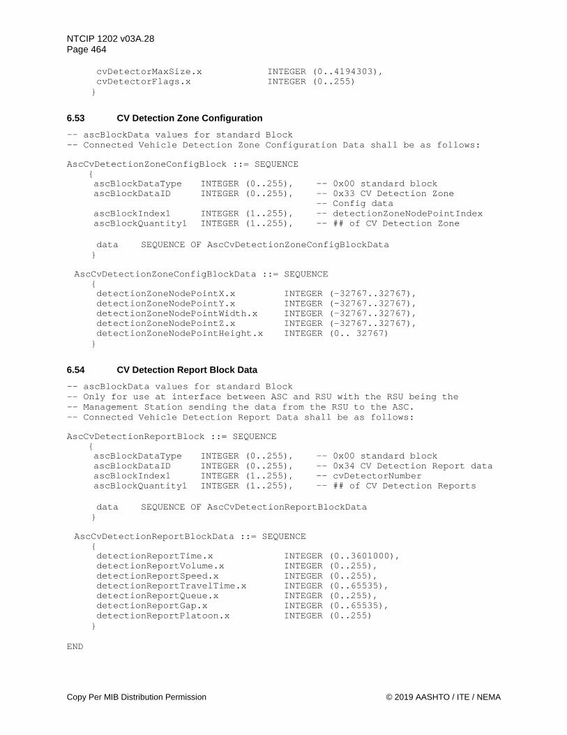
NTCIP 1202 v03A.28 Page 464
Copy Per MIB Distribution Permission © 2019 AASHTO / ITE / NEMA
cvDetectorMaxSize.x INTEGER (0..4194303), cvDetectorFlags.x INTEGER (0..255)
}
6.53 CV Detection Zone Configuration -- ascBlockData values for standard Block -- Connected Vehicle Detection Zone Configuration Data shall be as follows: AscCvDetectionZoneConfigBlock ::= SEQUENCE
{ ascBlockDataType INTEGER (0..255), -- 0x00 standard block ascBlockDataID INTEGER (0..255), -- 0x33 CV Detection Zone -- Config data ascBlockIndex1 INTEGER (1..255), -- detectionZoneNodePointIndex ascBlockQuantity1 INTEGER (1..255), -- ## of CV Detection Zone
data SEQUENCE OF AscCvDetectionZoneConfigBlockData
} AscCvDetectionZoneConfigBlockData ::= SEQUENCE
{ detectionZoneNodePointX.x INTEGER (-32767..32767), detectionZoneNodePointY.x INTEGER (-32767..32767), detectionZoneNodePointWidth.x INTEGER (-32767..32767), detectionZoneNodePointZ.x INTEGER (-32767..32767), detectionZoneNodePointHeight.x INTEGER (0.. 32767)
}
6.54 CV Detection Report Block Data -- ascBlockData values for standard Block -- Only for use at interface between ASC and RSU with the RSU being the -- Management Station sending the data from the RSU to the ASC. -- Connected Vehicle Detection Report Data shall be as follows: AscCvDetectionReportBlock ::= SEQUENCE
{ ascBlockDataType INTEGER (0..255), -- 0x00 standard block ascBlockDataID INTEGER (0..255), -- 0x34 CV Detection Report data ascBlockIndex1 INTEGER (1..255), -- cvDetectorNumber ascBlockQuantity1 INTEGER (1..255), -- ## of CV Detection Reports
data SEQUENCE OF AscCvDetectionReportBlockData
} AscCvDetectionReportBlockData ::= SEQUENCE
{ detectionReportTime.x INTEGER (0..3601000), detectionReportVolume.x INTEGER (0..255), detectionReportSpeed.x INTEGER (0..255), detectionReportTravelTime.x INTEGER (0..65535), detectionReportQueue.x INTEGER (0..255), detectionReportGap.x INTEGER (0..65535), detectionReportPlatoon.x INTEGER (0..255)
} END

NTCIP 1202 v03A.28 Page 465
© 2019 AASHTO / ITE / NEMA Copy Per MIB Distribution Permission
Section 7 SAE/NTCIP Object Definitions
This section is a snapshot of the MIB containing the object definitions that relate directly to the data set defined in SAE J2735_201603 to support the Connected Vehicle interface. The snapshot is provided, with permission from SAE, so users of NTCIP 1202 v03 document can correctly reference the correct object definitions in the NTCIP 1217 MIB. To obtain the complete MIB, including the full object definitions, please contact SAE. Section 1.2.3.5 provides the contact information for SAE. To review the full description and correct use of the corresponding SAE data elements, please refer to SAE J2735_201603. .
7.1 MIB Header --********************************************************************* -- Filename: 1217v0128.MIB -- Date: May 30, 2019 -- Description: This MIB is used -- in conjunction with SAE data elements --********************************************************************* NTCIP1217-v01 DEFINITIONS ::= BEGIN -- the following OBJECT IDENTIFIERS are used in the SAENTCIP MIB: IMPORTS OBJECT-TYPE FROM RFC-1212 DisplayString, ifIndex FROM RFC1213-MIB channelNumber FROM NTCIP1202-v03 Devices, OerString FROM NTCIP8004v02; saeNtcip OBJECT IDENTIFIER ::= { devices 17 } -- MapActivationCode ::= OCTET STRING (SIZE(3)) -- The MapActivationCode consists of those parameters required to activate -- a MAP Plan message in an ASC. It is defined as an OCTET STRING containing -- the OER-encoding of the following ASN.1 structure. -- mapActivationCodeStructure ::= SEQUENCE { -- mapPlanIndex INTEGER (1..8), -- mapPlanCRC OCTET STRING (SIZE (2)) } -- -- mapPlanIndex (8 bits) shall indicate the mapPlanIndex requested. --

NTCIP 1202 v03A.28 Page 466
Copy Per MIB Distribution Permission © 2019 AASHTO / ITE / NEMA
-- mapPlanCRC (16 bits) shall indicate the mapPlanCRC of the requested -- mapPlanIndex.
7.2 Signal Phase and Timing spat OBJECT IDENTIFIER ::= { saeNtcip 1 } -- This defines a node for supporting signal phase and timing objects for a connected vehicle environment.
7.2.1 Intersection Status spatStatus OBJECT-TYPE
DESCRIPTION "<Definition> For NTCIP 1202 user clarification, if a mode is enabled or active, the associated bit shall be set to (1). The definition of the term 'recent' is defined by the system in use. Bit 0 is equal to Bit 0 of the BIT STRING of DE_IntersectionStatusObject, Bit 1 is equal to Bit 1, etc.
Bit 0: Enabled when unitControlStatus is remoteManualControl (9) Bit 1: Enabled when Bit 4: Stop Time in unitAlarmStatus2 is TRUE Bit 2: Enabled when unitFlashStatus is other (1), faultMonitor (5) or
mmu (6) Bit 3: Enabled when the preemptState for any preempt is any value other
than other (1), notActive (2), or notActiveWithCall (3). Bit 4: Enabled if the CU is servicing a signal priority request. Bit 5: Enabled if the CU is operating in fixedTime mode. This bit and
bit 6 are mutually exclusive. Bit 6: Enabled if the CU is operating in an actuated mode. This bit and
bit 5 are mutually exclusive. Bit 7: Enabled if the unitFlashStatus is automatic (3), localManual (4)
or in startup (7) Bit 8: Controller failure or failure in operation. Bit 9: Reserved Bit 10: Enabled if a spatMapActivationCode value has changed within the
previous two coordination cycles. Bit 11: Enabled if the current cycle is the first cycle that a new set
of enabledLanesBits is used. Bit 12: Enabled if the mapActivatePlanError is any value other than
none (2). Bit 13: Enabled if any spatPortStatus object is any value other than
normal (3). <Object Identifier> 1.3.6.1.4.1.1206.4.2.17.1.1" REFERENCE "SAE J2735_201603 DE_IntersectionStatusObject"
::= { spat 1 }
7.2.2 Maximum SPaT Speed Advisories maxAdvisorySpeeds OBJECT-TYPE
SYNTAX INTEGER(0..16) ACCESS read-only STATUS mandatory DESCRIPTION "<Definition> This object contains the maximum number of
movement speed advisory entries this CU supports. This object indicates the maximum rows which shall appear in the advisorySpeedTable object.
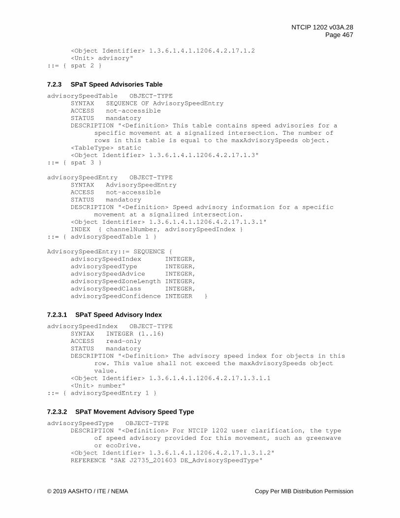
NTCIP 1202 v03A.28 Page 467
© 2019 AASHTO / ITE / NEMA Copy Per MIB Distribution Permission
<Object Identifier> 1.3.6.1.4.1.1206.4.2.17.1.2 <Unit> advisory"
::= { spat 2 }
7.2.3 SPaT Speed Advisories Table advisorySpeedTable OBJECT-TYPE
SYNTAX SEQUENCE OF AdvisorySpeedEntry ACCESS not-accessible STATUS mandatory DESCRIPTION "<Definition> This table contains speed advisories for a
specific movement at a signalized intersection. The number of rows in this table is equal to the maxAdvisorySpeeds object.
<TableType> static <Object Identifier> 1.3.6.1.4.1.1206.4.2.17.1.3"
::= { spat 3 } advisorySpeedEntry OBJECT-TYPE
SYNTAX AdvisorySpeedEntry ACCESS not-accessible STATUS mandatory DESCRIPTION "<Definition> Speed advisory information for a specific
movement at a signalized intersection. <Object Identifier> 1.3.6.1.4.1.1206.4.2.17.1.3.1" INDEX { channelNumber, advisorySpeedIndex }
::= { advisorySpeedTable 1 } AdvisorySpeedEntry::= SEQUENCE {
advisorySpeedIndex INTEGER, advisorySpeedType INTEGER, advisorySpeedAdvice INTEGER, advisorySpeedZoneLength INTEGER, advisorySpeedClass INTEGER, advisorySpeedConfidence INTEGER }
7.2.3.1 SPaT Speed Advisory Index advisorySpeedIndex OBJECT-TYPE
SYNTAX INTEGER (1..16) ACCESS read-only STATUS mandatory DESCRIPTION "<Definition> The advisory speed index for objects in this
row. This value shall not exceed the maxAdvisorySpeeds object value.
<Object Identifier> 1.3.6.1.4.1.1206.4.2.17.1.3.1.1 <Unit> number"
::= { advisorySpeedEntry 1 }
7.2.3.2 SPaT Movement Advisory Speed Type advisorySpeedType OBJECT-TYPE
DESCRIPTION "<Definition> For NTCIP 1202 user clarification, the type of speed advisory provided for this movement, such as greenwave or ecoDrive.
<Object Identifier> 1.3.6.1.4.1.1206.4.2.17.1.3.1.2" REFERENCE "SAE J2735_201603 DE_AdvisorySpeedType"
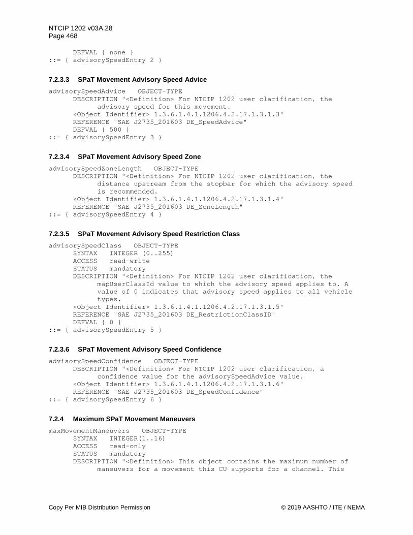
NTCIP 1202 v03A.28 Page 468
Copy Per MIB Distribution Permission © 2019 AASHTO / ITE / NEMA
DEFVAL { none } ::= { advisorySpeedEntry 2 }
7.2.3.3 SPaT Movement Advisory Speed Advice advisorySpeedAdvice OBJECT-TYPE
DESCRIPTION "<Definition> For NTCIP 1202 user clarification, the advisory speed for this movement.
<Object Identifier> 1.3.6.1.4.1.1206.4.2.17.1.3.1.3" REFERENCE "SAE J2735_201603 DE_SpeedAdvice" DEFVAL { 500 }
::= { advisorySpeedEntry 3 }
7.2.3.4 SPaT Movement Advisory Speed Zone advisorySpeedZoneLength OBJECT-TYPE
DESCRIPTION "<Definition> For NTCIP 1202 user clarification, the distance upstream from the stopbar for which the advisory speed is recommended.
<Object Identifier> 1.3.6.1.4.1.1206.4.2.17.1.3.1.4" REFERENCE "SAE J2735_201603 DE_ZoneLength"
::= { advisorySpeedEntry 4 }
7.2.3.5 SPaT Movement Advisory Speed Restriction Class advisorySpeedClass OBJECT-TYPE
SYNTAX INTEGER (0..255) ACCESS read-write STATUS mandatory DESCRIPTION "<Definition> For NTCIP 1202 user clarification, the
mapUserClassId value to which the advisory speed applies to. A value of 0 indicates that advisory speed applies to all vehicle types.
<Object Identifier> 1.3.6.1.4.1.1206.4.2.17.1.3.1.5" REFERENCE "SAE J2735_201603 DE_RestrictionClassID" DEFVAL { 0 }
::= { advisorySpeedEntry 5 }
7.2.3.6 SPaT Movement Advisory Speed Confidence advisorySpeedConfidence OBJECT-TYPE
DESCRIPTION "<Definition> For NTCIP 1202 user clarification, a confidence value for the advisorySpeedAdvice value.
<Object Identifier> 1.3.6.1.4.1.1206.4.2.17.1.3.1.6" REFERENCE "SAE J2735_201603 DE_SpeedConfidence"
::= { advisorySpeedEntry 6 }
7.2.4 Maximum SPaT Movement Maneuvers maxMovementManeuvers OBJECT-TYPE
SYNTAX INTEGER(1..16) ACCESS read-only STATUS mandatory DESCRIPTION "<Definition> This object contains the maximum number of
maneuvers for a movement this CU supports for a channel. This
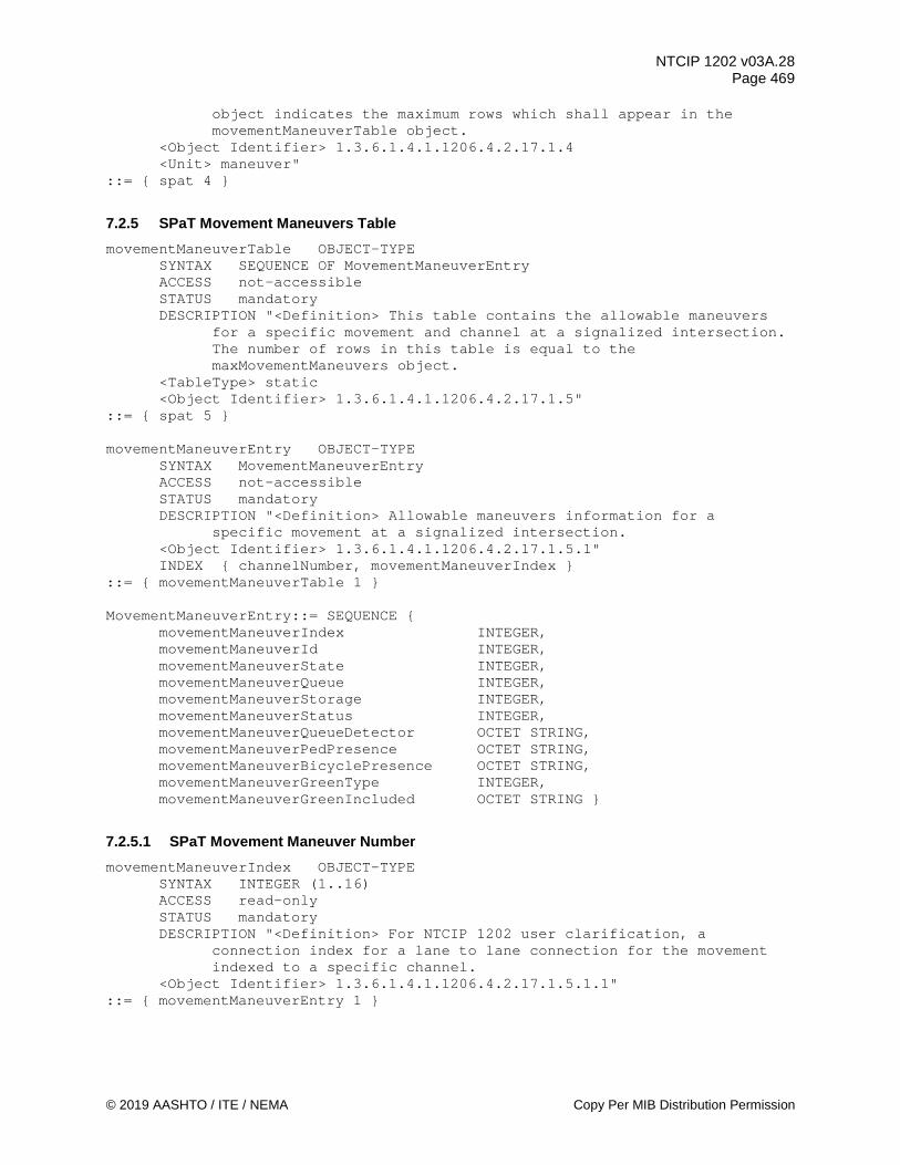
NTCIP 1202 v03A.28 Page 469
© 2019 AASHTO / ITE / NEMA Copy Per MIB Distribution Permission
object indicates the maximum rows which shall appear in the movementManeuverTable object.
<Object Identifier> 1.3.6.1.4.1.1206.4.2.17.1.4 <Unit> maneuver"
::= { spat 4 }
7.2.5 SPaT Movement Maneuvers Table movementManeuverTable OBJECT-TYPE
SYNTAX SEQUENCE OF MovementManeuverEntry ACCESS not-accessible STATUS mandatory DESCRIPTION "<Definition> This table contains the allowable maneuvers
for a specific movement and channel at a signalized intersection. The number of rows in this table is equal to the maxMovementManeuvers object.
<TableType> static <Object Identifier> 1.3.6.1.4.1.1206.4.2.17.1.5"
::= { spat 5 } movementManeuverEntry OBJECT-TYPE
SYNTAX MovementManeuverEntry ACCESS not-accessible STATUS mandatory DESCRIPTION "<Definition> Allowable maneuvers information for a
specific movement at a signalized intersection. <Object Identifier> 1.3.6.1.4.1.1206.4.2.17.1.5.1" INDEX { channelNumber, movementManeuverIndex }
::= { movementManeuverTable 1 } MovementManeuverEntry::= SEQUENCE {
movementManeuverIndex INTEGER, movementManeuverId INTEGER, movementManeuverState INTEGER, movementManeuverQueue INTEGER, movementManeuverStorage INTEGER, movementManeuverStatus INTEGER, movementManeuverQueueDetector OCTET STRING, movementManeuverPedPresence OCTET STRING, movementManeuverBicyclePresence OCTET STRING, movementManeuverGreenType INTEGER, movementManeuverGreenIncluded OCTET STRING }
7.2.5.1 SPaT Movement Maneuver Number movementManeuverIndex OBJECT-TYPE
SYNTAX INTEGER (1..16) ACCESS read-only STATUS mandatory DESCRIPTION "<Definition> For NTCIP 1202 user clarification, a
connection index for a lane to lane connection for the movement indexed to a specific channel.
<Object Identifier> 1.3.6.1.4.1.1206.4.2.17.1.5.1.1" ::= { movementManeuverEntry 1 }

NTCIP 1202 v03A.28 Page 470
Copy Per MIB Distribution Permission © 2019 AASHTO / ITE / NEMA
7.2.5.2 SPaT Movement Maneuver Identifier movementManeuverId OBJECT-TYPE
SYNTAX INTEGER (0..255) ACCESS read-write STATUS mandatory DESCRIPTION "<Definition> This object is used to uniquely identify a
lane to lane connection for the intersection. Can be used to relate SPaT data to a lane defined in the MAP messages. A value of 0 indicates that the row is disabled and all other values in the row are not valid.
<Object Identifier> 1.3.6.1.4.1.1206.4.2.17.1.5.1.2" REFERENCE "SAE J2735_201603 DF_ConnectionManeuverAssist and
DE_LaneConnectionID" ::= { movementManeuverEntry 2 }
7.2.5.3 SPaT Movement Maneuver State movementManeuverState OBJECT-TYPE
SYNTAX INTEGER (0..9) ACCESS read-only STATUS mandatory DESCRIPTION "<Definition> For NTCIP 1202 user clarification, this
object defines the state of a specific movement maneuver (lane connection) at the intersection, unlike signalState, which defines the general state of a channel. This object value is determined as follows where Column A is the movementManeuverGreenType, Column B is the movementManeuverGreenIncluded, and Column C is the channel output for the channelNumber:
+-----------------+-----------------+-----+-----------------+--------+ | movementManeuver| | | | | | State | A | B | C | Notes | +-----------------+-----------------+-----+-----------------+--------+ | unavailable (0) | Any | Any | Unavailable | | | 1 - See Note G | Any | Any | See Note A | | | 2 - See Note G | flashRed (5) | 0 | Green or Red | | | 3 - See Note G | Any | Any | Red | Note B | | 4 - See Note G | N/A | N/A | N/A | | | 5 - See Note G | permissive (3) | 0 | Green | | | 5 - See Note G | protected (2) | > 0 |Not Yellow or Red| Note C | | 6 - See Note G | protected (2) | > 0 |Not Yellow or Red| Note D | | 6 - See Note G | protected (2) | 0 | Green | | | 7 - See Note G | Any | Any | Yellow | Note E | | 8 - See Note G | protected (2) | Any | Yellow | Note F | | 9 - See Note G | flashYellow (4) | 0 | Green or Yellow | | +-----------------+-----------------+-----+-----------------+--------+ Note A: Not Green, Yellow or Red. Note B: If this movement maneuver is controlled by a 4-section head or
5-section head, and the signal indication is 'Red', then this movement maneuver is also considered 'Red'.
Note C: If one or more of the octets in movementManeuverGreenIncluded is NOT 'Red' or is Dark.
Note D: If all octets in movementManeuverGreenIncluded are 'Red'. Note E: Only if the preceding movementManeuverState was permissive-
movement-allowed.

NTCIP 1202 v03A.28 Page 471
© 2019 AASHTO / ITE / NEMA Copy Per MIB Distribution Permission
Note F: Only if the preceding movementManeuverState was protected-movement-allowed.
Note G: The definition of the value can be found in SAE J2735_201603 DE_MovementPhaseState.
For example, the object value is '6' if the movementManeuverGreenType
is protected (2), and all octets in movementManeuverGreenIncluded (each representing a channelNumber) are 'Red'; OR if the movementManeuverGreenType is protected (2) and the movementManeuverGreenIncluded is 00.
If the movementManeuverTable is used, this object may be exchanged between the ASC and the CV Roadside Process in lieu of the signalState object.
<Object Identifier> 1.3.6.1.4.1.1206.4.2.17.1.5.1.3" REFERENCE "SAE J2735_201603 DE_MovementPhaseState"
::= { movementManeuverEntry 3 }
7.2.5.4 SPaT Movement Queue movementManeuverQueue OBJECT-TYPE
DESCRIPTION "<Definition> For NTCIP 1202 user clarification, the distance from the stop line at the intersection for this movement to the back edge of the last vehicle in the queue.
<Object Identifier> 1.3.6.1.4.1.1206.4.2.17.1.5.1.4" REFERENCE "SAE J2735_201603 DF_ConnectionManeuverAssist and
DE_ZoneLength" DEFVAL { 0 }
::= { movementManeuverEntry 4 }
7.2.5.5 SPaT Movement Storage movementManeuverStorage OBJECT-TYPE
DESCRIPTION "<Definition> For NTCIP 1202 user clarification, the distance with a high probability for successfully executing the connecting maneuver between the approach lane and the egress lane during the current cycle.
<Object Identifier> 1.3.6.1.4.1.1206.4.2.17.1.5.1.5" REFERENCE "SAE J2735_201603 DF_ConnectionManeuverAssist and
DE_ZoneLength" DEFVAL { 0 }
::= { movementManeuverEntry 5 }
7.2.5.6 SPaT Movement Assist Status movementManeuverStatus OBJECT-TYPE
SYNTAX INTEGER (0..255) ACCESS read-only STATUS mandatory DESCRIPTION "<Definition> For NTCIP 1202 user clarification, this
object defines the options for traveler connections through an intersection. Bit 7: Reserved Bit 6: Reserved Bit 5: Reserved Bit 4: Reserved Bit 3: Reserved

NTCIP 1202 v03A.28 Page 472
Copy Per MIB Distribution Permission © 2019 AASHTO / ITE / NEMA
Bit 2: Reserved Bit 1: Status bit set to TRUE (1) if ANY pedestrians or bicyclists are detected in a conflicting movement. Set to FALSE (0) if there is a high certainty no pedestrians or bicyclists are present. Bit 0: Set to TRUE (1) if vehicles for this movement maneuver have to stop on the stop-line and not enter the intersection. A SET of a 'reserved' bit of Bit 1 to a value other than zero (0) shall return a badValue(3) error.
<Object Identifier> 1.3.6.1.4.1.1206.4.2.17.1.5.1.6" REFERENCE "SAE J2735_201603 DE_WaitOnStopline and
DE_PedestrianBicycleDetect" ::= { movementManeuverEntry 6 }
7.2.5.7 SPaT Movement Queue Detector movementManeuverQueueDetector OBJECT-TYPE
SYNTAX OCTET STRING ACCESS read-write STATUS mandatory DESCRIPTION "<Definition> Each octet in this octet string represents a
vehicle detector number (vehicleDetectorNumber) in the vehicleDetectorTable that provides the data to determine movementManeuverQueue. A value of 00 indicates that no additional vehicle detectors follow in the octet string.
<Object Identifier> 1.3.6.1.4.1.1206.4.2.17.1.5.1.7" ::= { movementManeuverEntry 7 }
7.2.5.8 SPaT Movement Pedestrian Presence movementManeuverPedPresence OBJECT-TYPE
SYNTAX OCTET STRING ACCESS read-write STATUS mandatory DESCRIPTION "<Definition> Each octet in this octet string represents a
pedestrian detector number (pedestrianDetectorNumber) in the pedestrianDetectorTable (with Bit 0 in the corresponding pedestrianDetectorOptions Enabled) whose detection status indicates a pedestrian is detected in the pedestrian crossing that conflicts with this movementManeuverIndex. For example, an octet string of 01 03 indicates that if pedestrian detector 1 or pedestrian detector 3 is active/ON, then the presence of a pedestrian has been detected that conflicts with this movementManeuverIndex. If a pedestrian is detected by any pedestrianDetectorNumber in the octet string, Bit 1 in movementManeuverStatus shall be SET to TRUE (1).
<Object Identifier> 1.3.6.1.4.1.1206.4.2.17.1.5.1.8" ::= { movementManeuverEntry 8 }
7.2.5.9 SPaT Movement Bicycle Presence movementManeuverBicyclePresence OBJECT-TYPE
SYNTAX OCTET STRING ACCESS read-write STATUS mandatory

NTCIP 1202 v03A.28 Page 473
© 2019 AASHTO / ITE / NEMA Copy Per MIB Distribution Permission
DESCRIPTION "<Definition> Each octet in this octet string represents a vehicle detector number (vehicleDetectorNumber) in the vehicleDetectorTable that when active/ON indicates that a bicyclist is detected that conflicts with this movementManeuverIndex. If a bicyclist is detected by any of the vehicleDetectorNumber in the octet string, Bit 1 in movementManeuverStatus shall be SET to TRUE (1). For example, an octet string of 02 06 indicates that if vehicle detector 2 or vehicle detector 6 is active/ON, then the presence of a bicyclist has been detected that conflicts with this movementManeuverIndex.
<Object Identifier> 1.3.6.1.4.1.1206.4.2.17.1.5.1.9" ::= { movementManeuverEntry 9 }
7.2.5.10 SPaT Movement Type movementManeuverGreenType OBJECT-TYPE
SYNTAX INTEGER { other (1), protected (2), permissive (3), flashYellow (4), flashRed (5) } ACCESS read-write STATUS mandatory DESCRIPTION "<Definition> This object defines the movementManeuverState
for this specific movement maneuver when the channel output is Green. This object is used to support the generation of SPAT data. other: the allowed movement controlled by this channel is not defined by this standard. protected: indicates that at least a portion of the green movement occurs in protected mode. permissive: indicates that the green movement occurs in permissive mode, that is, any turns are permitted to be made only after yielding to pedestrians and/or any opposing traffic. flashYellow: indicates that a vehicle may proceed but with caution after yielding to pedestrians and/or any conflicting traffic. Includes flashing yellow arrows. flashRed: indicates that a vehicle may proceed after stopping and yielding to pedestrians and/or any conflicting traffic. Includes flashing red arrows. Note there is a similar object called channelGreenType that identifies the state when the channel output is Green in general.
<Object Identifier> 1.3.6.1.4.1.1206.4.2.17.1.5.1.10" ::= { movementManeuverEntry 10 }
7.2.5.11 SPaT Movement Included Movements movementManeuverGreenIncluded OBJECT-TYPE
SYNTAX OCTET STRING ACCESS read-write STATUS mandatory DESCRIPTION "<Definition> If the movementManeuverGreenType for this
movement maneuver is 'protected (2)', this object is used to indicate if and when this movement maneuver is in permissive mode. This object is used to support the generation of SPAT data and defines the movementManeuverState for this movement maneuver only IF the maneuverMovementGreenType is 'protected (2)'. Each
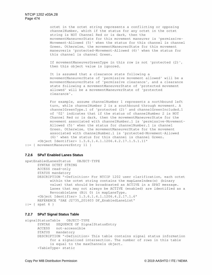
NTCIP 1202 v03A.28 Page 474
Copy Per MIB Distribution Permission © 2019 AASHTO / ITE / NEMA
octet in the octet string represents a conflicting or opposing channelNumber, which if the status for any octet in the octet string is NOT Channel Red or is dark, then the movementManeuverState for this movement maneuver is 'permissive-Movement-Allowed (5)' when the status for this channel is channel Green. Otherwise, the movementManeuverState for this movement maneuveris 'protected-Movement-Allowed (6)' when the status for this channel is channel Green.
If movementManeuverGreenType in this row is not 'protected (2)',
then this object value is ignored. It is assumed that a clearance state following a movementManeuverState of 'permissive movement allowed' will be a movementManeuverState of 'permissive clearance', and a clearance state following a movementManeuverState of 'protected movement allowed' will be a movementManeuverState of 'protected clearance'. For example, assume channelNumber 1 represents a northbound left turn, while channelNumber 2 is a southbound through movement. A channelGreenType.1 of 'protected (2)' and channelGreenIncluded.1 of '02' indicates that if the status of channelNumber 2 is NOT Channel Red or is dark, then the movementManeuverState for the movement associated with channelNumber.1 is 'permissive-Movement-Allowed (5)' when the status for channelNumber.1 is channel Green. Otherwise, the movementManeuverState for the movement associated with channelNumber.1 is 'protected-Movement-Allowed (6)' when the status for this channel is channel Green.
<Object Identifier> 1.3.6.1.4.1.1206.4.2.17.1.5.1.11" ::= { movementManeuverEntry 11 }
7.2.6 SPaT Enabled Lanes Status spatEnabledLanesStatus OBJECT-TYPE
SYNTAX OCTET STRING ACCESS read-only STATUS mandatory DESCRIPTION "<Definition> For NTCIP 1202 user clarification, each octet
within the octet string contains the mapLaneIndex(s) (binary value) that should be broadcasted as ACTIVE in a SPAT message. Lanes that may not always be ACTIVE (enabled) are identified as a RevocableLane (Bit 0) in mapLaneType.
<Object Identifier> 1.3.6.1.4.1.1206.4.2.17.1.6" REFERENCE "SAE J2735_201603 DF_EnabledLaneList"
::= { spat 6 }
7.2.7 SPaT Signal Status Table signalStatusTable OBJECT-TYPE
SYNTAX SEQUENCE OF SignalStatusEntry ACCESS not-accessible STATUS mandatory DESCRIPTION "<Definition> This table contains signal status information
for a signalized intersection. The number of rows in this table is equal to the maxChannels object.
<TableType> static
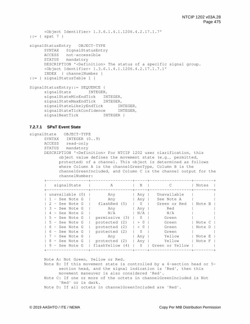
NTCIP 1202 v03A.28 Page 475
© 2019 AASHTO / ITE / NEMA Copy Per MIB Distribution Permission
<Object Identifier> 1.3.6.1.4.1.1206.4.2.17.1.7" ::= { spat 7 } signalStatusEntry OBJECT-TYPE
SYNTAX SignalStatusEntry ACCESS not-accessible STATUS mandatory DESCRIPTION "<Definition> The status of a specific signal group. <Object Identifier> 1.3.6.1.4.1.1206.4.2.17.1.7.1" INDEX { channelNumber }
::= { signalStatusTable 1 } SignalStatusEntry::= SEQUENCE { signalState INTEGER,
signalStateMinEndTick INTEGER, signalStateMaxEndTick INTEGER, signalStateLikelyEndTick INTEGER, signalStateTickConfidence INTEGER, signalNextTick INTEGER }
7.2.7.1 SPaT Event State signalState OBJECT-TYPE
SYNTAX INTEGER (0..9) ACCESS read-only STATUS mandatory DESCRIPTION "<Definition> For NTCIP 1202 user clarification, this
object value defines the movement state (e.g., permitted, protected) of a channel. This object is determined as follows where Column A is the channelGreenType, Column B is the channelGreenIncluded, and Column C is the channel output for the channelNumber:
+-----------------+-----------------+-----+-----------------+--------+ | signalState | A | B | C | Notes | +-----------------+-----------------+-----+-----------------+--------+ | unavailable (0) | Any | Any | Unavailable | | | 1 - See Note G | Any | Any | See Note A | | | 2 - See Note G | flashRed (5) | 0 | Green or Red | Note B | | 3 - See Note G | Any | Any | Red | | | 4 - See Note G | N/A | N/A | N/A | | | 5 - See Note G | permissive (3) | 0 | Green | | | 5 - See Note G | protected (2) | > 0 | Green | Note C | | 6 - See Note G | protected (2) | > 0 | Green | Note D | | 6 - See Note G | protected (2) | 0 | Green | | | 7 - See Note G | Any | Any | Yellow | Note E | | 8 - See Note G | protected (2) | Any | Yellow | Note F | | 9 - See Note G | flashYellow (4) | 0 | Green or Yellow | | +-----------------+-----------------+-----+-----------------+--------+ Note A: Not Green, Yellow or Red. Note B: If this movement state is controlled by a 4-section head or 5-
section head, and the signal indication is 'Red', then this movement maneuver is also considered 'Red'.
Note C: If one or more of the octets in channelGreenIncluded is Not 'Red' or is dark.
Note D: If all octets in channelGreenIncluded are 'Red'.
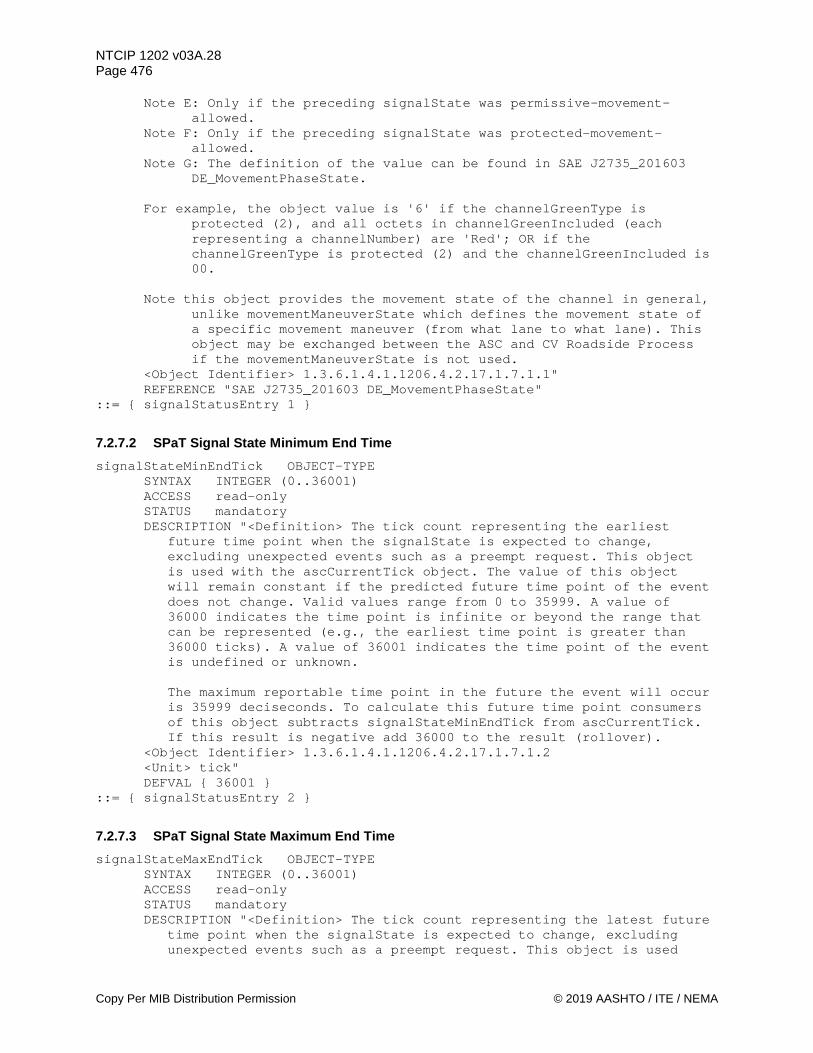
NTCIP 1202 v03A.28 Page 476
Copy Per MIB Distribution Permission © 2019 AASHTO / ITE / NEMA
Note E: Only if the preceding signalState was permissive-movement-allowed.
Note F: Only if the preceding signalState was protected-movement-allowed.
Note G: The definition of the value can be found in SAE J2735_201603 DE_MovementPhaseState.
For example, the object value is '6' if the channelGreenType is
protected (2), and all octets in channelGreenIncluded (each representing a channelNumber) are 'Red'; OR if the channelGreenType is protected (2) and the channelGreenIncluded is 00.
Note this object provides the movement state of the channel in general,
unlike movementManeuverState which defines the movement state of a specific movement maneuver (from what lane to what lane). This object may be exchanged between the ASC and CV Roadside Process if the movementManeuverState is not used.
<Object Identifier> 1.3.6.1.4.1.1206.4.2.17.1.7.1.1" REFERENCE "SAE J2735_201603 DE_MovementPhaseState"
::= { signalStatusEntry 1 }
7.2.7.2 SPaT Signal State Minimum End Time signalStateMinEndTick OBJECT-TYPE
SYNTAX INTEGER (0..36001) ACCESS read-only STATUS mandatory DESCRIPTION "<Definition> The tick count representing the earliest
future time point when the signalState is expected to change, excluding unexpected events such as a preempt request. This object is used with the ascCurrentTick object. The value of this object will remain constant if the predicted future time point of the event does not change. Valid values range from 0 to 35999. A value of 36000 indicates the time point is infinite or beyond the range that can be represented (e.g., the earliest time point is greater than 36000 ticks). A value of 36001 indicates the time point of the event is undefined or unknown. The maximum reportable time point in the future the event will occur is 35999 deciseconds. To calculate this future time point consumers of this object subtracts signalStateMinEndTick from ascCurrentTick. If this result is negative add 36000 to the result (rollover).
<Object Identifier> 1.3.6.1.4.1.1206.4.2.17.1.7.1.2 <Unit> tick" DEFVAL { 36001 }
::= { signalStatusEntry 2 }
7.2.7.3 SPaT Signal State Maximum End Time signalStateMaxEndTick OBJECT-TYPE
SYNTAX INTEGER (0..36001) ACCESS read-only STATUS mandatory DESCRIPTION "<Definition> The tick count representing the latest future
time point when the signalState is expected to change, excluding unexpected events such as a preempt request. This object is used

NTCIP 1202 v03A.28 Page 477
© 2019 AASHTO / ITE / NEMA Copy Per MIB Distribution Permission
with the ascCurrentTick object. The value of this object will remain constant if the predicted future time point of the event does not change. Valid values range from 0 to 35999. A value of 36000 indicates the time point is infinite or beyond the range that can be represented (e.g., the latest time point is greater than 36000 ticks). A value of 36001 indicates the time point of the event is undefined or unknown. The maximum reportable time point in the future the event will occur is 35999 deciseconds. To calculate this future time point consumers of this object subtracts signalStateMaxEndTick from ascCurrentTick. If this result is negative add 36000 to the result (rollover).
<Object Identifier> 1.3.6.1.4.1.1206.4.2.17.1.7.1.3 <Unit> tick" DEFVAL { 36001 }
::= { signalStatusEntry 3 }
7.2.7.4 SPaT Signal State Likely Time signalStateLikelyEndTick OBJECT-TYPE
SYNTAX INTEGER (0..36001) ACCESS read-only STATUS mandatory DESCRIPTION "<Definition> The tick count representing the most likely
future time point when the signalState is expected to change, excluding unexpected events such as a preempt request. This object is used with the ascCurrentTick object. The value of this object will remain constant if the predicted future time point of the event does not change. Valid values range from 0 to 35999. A value of 36000 indicates the time point is infinite or beyond the range that can be represented (e.g., the likely time point is greater than 36000 ticks). A value of 36001 indicates the time point of the event is undefined or unknown. The maximum reportable time point in the future the event will occur is 35999 deciseconds. To calculate this future time point consumers of this object subtracts signalStateLikelyEndTick from ascCurrentTick. If this result is negative add 36000 to the result (rollover).
<Object Identifier> 1.3.6.1.4.1.1206.4.2.17.1.7.1.4 <Unit> tick" DEFVAL { 36001 }
::= { signalStatusEntry 4 }
7.2.7.5 SPaT Signal State Time Confidence signalStateTickConfidence OBJECT-TYPE
SYNTAX INTEGER (0..15) ACCESS read-only STATUS mandatory DESCRIPTION "<Definition> For NTCIP 1202 user clarification, the
statistical confidence in the predicted value of the signalStateLikelyTick.
<Object Identifier> 1.3.6.1.4.1.1206.4.2.17.1.7.1.5" REFERENCE "SAE J2735_201603 DE_TimeIntervalConfidence"
::= { signalStatusEntry 5 }

NTCIP 1202 v03A.28 Page 478
Copy Per MIB Distribution Permission © 2019 AASHTO / ITE / NEMA
7.2.7.6 SPaT Signal Next Tick signalNextTick OBJECT-TYPE
SYNTAX INTEGER (0..36001) ACCESS read-only STATUS mandatory DESCRIPTION "<Definition> The tick count representing the most likely
future time point when the movement is expected to be allowed to move again (e.g., green), excluding unexpected events such as a preempt request. This object is used with the ascCurrentTick object. The value of this object will remain constant if the predicted future time point of the event does not change. Valid values range from 0 to 35999. A value of 36000 indicates the time point is infinite or beyond the range that can be represented (e.g., the time point is greater than 36000 ticks). A value of 36001 indicates the time point of the event is undefined or unknown. If the current signalState is not a red light or in a clearance interval, then a value of 36001 is used. The maximum reportable time point in the future the event will occur is 35999 deciseconds. To calculate this future time point consumers of this object subtracts signalNextTick from ascCurrentTick. If this result is negative add 36000 to the result (rollover).
<Object Identifier> 1.3.6.1.4.1.1206.4.2.17.1.7.1.6 <Unit> tick" DEFVAL { 36001 }
::= { signalStatusEntry 6 }
7.2.8 SPaT Signal Status Block signalStatusBlock OBJECT-TYPE
SYNTAX OerString ACCESS read-write STATUS mandatory DESCRIPTION "<Definition> An OER encoded string of the
signalStatusTable structure as defined below. This object is used for uploading configuration data from the ASC in a bandwidth efficient manner. The following data is repeated for each channel. OPTIONAL fields shall be present only if there are changes in the data values and if the data is supported by the implementation. The OPTIONAL fields shall be omitted for any data that has not changed from a previously transmitted object or not supported by the implementation.
signalStatus ::= SEQUENCE {
ascCurrentTick.0, -- @NTCIP1202-v03, Bytes 1 & 2 channelData SEQUENCE OF channelSignalData OPTIONAL
} channelSignalData ::== SEQUENCE {
channelNumber.x -- 1 BYTE @NTCIP1202-v03 signalStatusBitMask.x -- 1 BYTE signalState.x OPTIONAL, -- 1 BYTE @NTCIP1202-v03 signalStateMinEndTick.x OPTIONAL, -- 2 BYTES @NTCIP1202-v03 signalStateMaxEndTick.x OPTIONAL, -- 2 BYTES @NTCIP1202-v03 signalStateLikelyEndTick.x OPTIONAL, -- 2 BYTES @NTCIP1202-v03 signalStateTickConfidence.x OPTIONAL, -- 1 BYTE @NTCIP1202-v03

NTCIP 1202 v03A.28 Page 479
© 2019 AASHTO / ITE / NEMA Copy Per MIB Distribution Permission
signalNextTick.x OPTIONAL -- 2 BYTES @NTCIP1202-v03 } where: signalStatusBitMask is a bit mask (INTEGER (0..255)) defining the data that follows in the OerString. When a bit=1, the data is included in the OerString. If a bit=0, the corresponding data is omitted and not in the OER string.
Bit 7: Reserved Bit 6: Reserved Bit 5: signalNextTick - reference tick to next green state data
is present. Values are 0..36001. 36001 means could not calculate or undefined.
Bit 4: signalStateTickConfidence data for this channel is present (1 byte).
Bit 3: signalStateLikelyEndTick data for this channel is present (2 bytes). Values are 0..36001. 36001 means could not calculate or undefined.
Bit 2: signalStateMaxEndTick data for this channel is present (2 bytes). Values are 0..36001. 36001 means could not calculate or undefined.
Bit 1: signalStateMinEndTick data for this channel is present (2 bytes). Values are 0..36001. 36001 means could not calculate or undefined.
Bit 0: signalState data for this channel is present (1 byte). <Object Identifier> 1.3.6.1.4.1.1206.4.2.17.1.8"
::= { spat 8 }
7.2.9 SPaT Movement Maneuver Status Block movementManeuverStatusBlock OBJECT-TYPE
SYNTAX OerString ACCESS read-write STATUS mandatory DESCRIPTION "<Definition> An OER encoded string of the
movementManeuverTable structure as defined below. This object is used for uploading configuration data from the ASC in a bandwidth efficient manner. The following data is repeated for each channel. OPTIONAL fields shall be present only if there are changes in the data values and if the data is supported by the implementation. The OPTIONAL fields shall be omitted for any data that has not changed from a previously transmitted object or not supported by the implementation.
movementManeuverStatus ::= SEQUENCE {
ascCurrentTick.0, -- @NTCIP1202-v03, Bytes 1 & 2 movementManeuverData SEQUENCE OF movementManeuverStatusData
OPTIONAL } movementManeuverStatusData ::== SEQUENCE {
channelNumber.x -- 1 BYTE @NTCIP1202-v03 movementManeuverCount.x -- 1 BYTE movementManeuverIndex.x.y -- 1 BYTE @NTCIP1202-v03 movementManeuverBitMask.x.y -- 1 BYTE movementManeuverState.x.y OPTIONAL, -- 1 BYTE @NTCIP1202-v03
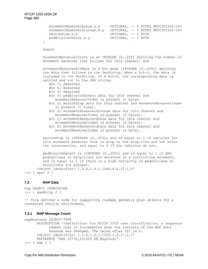
NTCIP 1202 v03A.28 Page 480
Copy Per MIB Distribution Permission © 2019 AASHTO / ITE / NEMA
movementManeuverQueue.x.y OPTIONAL, -- 2 BYTES @NTCIP1202-v03 movementManeuverStorage.x.y OPTIONAL, -- 2 BYTES @NTCIP1202-v03 waitOnStop.x.y OPTIONAL, -- 1 BYTE pedBicycleDetect.x.y OPTIONAL, -- 1 BYTE
} where: movementManueuverCount is an INTEGER (0..255) defining the number of movement maneuver that follows for this channel; and movementManeuverBitMask is a bit mask (INTEGER (0..255)) defining the data that follows in the OerString. When a bit=1, the data is included in the OerString. If a bit=0, the corresponding data is omitted and not in the OER string.
Bit 7: Reserved Bit 6: Reserved Bit 5: Reserved Bit 4: pedBicycleDetect data for this channel and
movementManeuverIndex is present (1 byte). Bit 3: waitOnStop data for this channel and movementManeuverIndex
is present (1 byte). Bit 2: movementManeuverStorage data for this channel and
movementManeuverIndex is present (2 bytes). Bit 1: movementManeuverQueue data for this channel and
movementManeuverIndex is present (2 bytes). Bit 0: movementManeuverState data for this channel and
movementManeuverIndex is present (1 byte). waitOnStop is (INTEGER (0..255)) and is equal to 1 if vehicles for this movement maneuver have to stop on the stop-line and not enter the intersection, and equal to 2 if the vehicles do not. pedBicycleDetect is (INTEGER (0..255)) and is equal to 1 if ANY pedestrians or bicyclists are detected in a conflicting movement, and is equal to 2 if there is a high certainty no pedestrians or bicyclists are present.
<Object Identifier> 1.3.6.1.4.1.1206.4.2.17.1.9" ::= { spat 9 }
7.3 MAP Data map OBJECT IDENTIFIER ::= { saeNtcip 2 } -- This defines a node for supporting roadway geometry plan objects for a connected vehicle environment.
7.3.1 MAP Message Count mapMsgCount OBJECT-TYPE
DESCRIPTION "<Definition> For NTCIP 1202 user clarification, a sequence number that is incremented when the contents of the MAP data message has changed. The value after 127 is 0.
<Object Identifier> 1.3.6.1.4.1.1206.4.2.17.2.1" REFERENCE "SAE J2735_201603 DE_MsgCount"
::= { map 1 }

NTCIP 1202 v03A.28 Page 481
© 2019 AASHTO / ITE / NEMA Copy Per MIB Distribution Permission
7.3.2 MAP Message Time mapMessageTime OBJECT-TYPE
DESCRIPTION "<Definition> For NTCIP 1202 user clarification, this object indicates the minute of the year the MAP data message was last created by the RSU.
<Object Identifier> 1.3.6.1.4.1.1206.4.2.17.2.2" REFERENCE "SAE J2735_201603 DE_MinuteOfTheYear" DEFVAL { 0 }
::= { map 2 }
7.3.3 Maximum Number of Lanes maxLanes OBJECT-TYPE
SYNTAX INTEGER(1..255) ACCESS read-only STATUS mandatory DESCRIPTION "<Definition> This object contains the maximum number of
lane entries this CU supports. This object indicates the maximum rows which shall appear in the mapLaneTable object.
<Object Identifier> 1.3.6.1.4.1.1206.4.2.17.2.3 <Unit> lanes"
::= { map 3 }
7.3.4 Intersection Lane Table mapLaneTable OBJECT-TYPE
SYNTAX SEQUENCE OF MapLaneEntry ACCESS not-accessible STATUS mandatory DESCRIPTION "<Definition> This table contains lane information for
intersections. The number of rows in this table is equal to the maxLanes object.
<TableType> static <Object Identifier> 1.3.6.1.4.1.1206.4.2.17.2.4"
::= { map 4 } mapLaneEntry OBJECT-TYPE
SYNTAX MapLaneEntry ACCESS not-accessible STATUS mandatory DESCRIPTION "<Definition> The parameters for a specific lane at an
intersection. <Object Identifier> 1.3.6.1.4.1.1206.4.2.17.2.4.1" INDEX { mapLaneIndex }
::= { mapLaneTable 1 } MapLaneEntry::= SEQUENCE { mapLaneIndex INTEGER, mapLaneIntersection INTEGER,
mapLaneNumber INTEGER, mapLaneName DisplayString, mapLaneDirection INTEGER, mapLaneSharing INTEGER, mapLaneType INTEGER,

NTCIP 1202 v03A.28 Page 482
Copy Per MIB Distribution Permission © 2019 AASHTO / ITE / NEMA
mapLaneAttribute INTEGER, mapLaneManeuver INTEGER, mapLaneOverlay OCTET STRING, mapLaneIngress INTEGER, mapLaneEgress INTEGER, mapLaneCRC OCTET STRING }
7.3.4.1 Lane Index mapLaneIndex OBJECT-TYPE
SYNTAX INTEGER (1..255) ACCESS read-only STATUS mandatory DESCRIPTION "<Definition> The lane index of objects in this row. The
entries in each row define the attributes of a specific lane (mapLaneNumber) at a referenced intersection (mapLaneIntersection). This value shall not exceed the maxLanes object value.
<Object Identifier> 1.3.6.1.4.1.1206.4.2.17.2.4.1.1 <Unit> lane"
::= { mapLaneEntry 1 }
7.3.4.2 Lane Intersection mapLaneIntersection OBJECT-TYPE
SYNTAX INTEGER (1..255) ACCESS read-write STATUS mandatory DESCRIPTION "<Definition> The index of the intersection
(mapIntersectionIndex) that this lane is associated with. <Object Identifier> 1.3.6.1.4.1.1206.4.2.17.2.4.1.2 <Unit> lane"
::= { mapLaneEntry 2 }
7.3.4.3 Lane Number mapLaneNumber OBJECT-TYPE
DESCRIPTION "<Definition> For NTCIP 1202 user clarification, the identifier of the lane of the referenced intersection (mapLaneIntersection).
<Object Identifier> 1.3.6.1.4.1.1206.4.2.17.2.4.1.3" REFERENCE "SAE J2735_201603 DF_GenericLane and DE_LaneID"
::= { mapLaneEntry 3 }
7.3.4.4 Lane Name mapLaneName OBJECT-TYPE
DESCRIPTION "<Definition> For NTCIP 1202 user clarification, a textual string describing the lane.
<Object Identifier> 1.3.6.1.4.1.1206.4.2.17.2.4.1.4" REFERENCE "SAE J2735_201603 DF_GenericLane and DE_DescriptiveName"
::= { mapLaneEntry 4 }
7.3.4.5 Lane Direction mapLaneDirection OBJECT-TYPE
NTCIP 1202 v03A.28 Page 483
© 2019 AASHTO / ITE / NEMA Copy Per MIB Distribution Permission
DESCRIPTION "<Definition> For NTCIP 1202 user clarification, this object denotes the allowed direction of travel over the lane.
<Object Identifier> 1.3.6.1.4.1.1206.4.2.17.2.4.1.5" REFERENCE "SAE J2735_201603 DE_LaneDirection" DEFVAL { 0 }
::= { mapLaneEntry 5 }
7.3.4.6 Lane Sharing mapLaneSharing OBJECT-TYPE
DESCRIPTION "<Definition> For NTCIP 1202 user clarification, this object describes other users (travel modes) with equal rights and access to the lane.
<Object Identifier> 1.3.6.1.4.1.1206.4.2.17.2.4.1.6" REFERENCE "SAE J2735_201603 DE_LaneSharing" DEFVAL { 0 }
::= { mapLaneEntry 6 }
7.3.4.7 Lane Type mapLaneType OBJECT-TYPE
SYNTAX INTEGER { vehicle (0), -- motor vehicle lanes crosswalk (1), -- pedestrian crosswalk bikelane (2), -- bike lane sidewalk (3), -- pedestrian sidewalk path median (4), -- median and channelization striping (5), -- roadway marking trackedvehicle (6), -- trains, trolleys, light rail parking (7) } -- parking or stopping lane
ACCESS read-write STATUS mandatory DESCRIPTION "<Definition> For NTCIP 1202 user clarification, this
object defines the type of lane. This value is used to determine the meaning of the values in mapLaneAttribute.
<Object Identifier> 1.3.6.1.4.1.1206.4.2.17.2.4.1.7" REFERENCE "SAE J2735_201603 DF_LaneTypeAttributes" DEFVAL { vehicle }
::= { mapLaneEntry 7 }
7.3.4.8 Lane Attribute mapLaneAttribute OBJECT-TYPE
DESCRIPTION "<Definition> For NTCIP 1202 user clarification, if a specific attribute for the lane is true, the associated bit shall be set to (1). Bit 0 is equal to Bit 0 of the BIT STRING of the appropriate LaneAttribute type, Bit 1 is equal to Bit 1, etc. If the mapLaneType is vehicle (0), then the attribute values are defined by SAE J2735_201603 DE_LaneAttributes-Vehicle.
If the mapLaneType is crosswalk (1), then the attribute values are defined by SAE J2735_201603 DE_LaneAttributes-Crosswalk.
If the mapLaneType is bikelane (2), then the attribute values are defined by SAE J2735_201603 DE_LaneAttributes-Bike.
If the mapLaneType is sidewalk (3), then the attribute values are defined by SAE J2735_201603 DE_LaneAttributes-Sidewalk.
If the mapLaneType is median (4), then the attribute values are defined by SAE J2735_201603 DE_LaneAttributes-Barrier.

NTCIP 1202 v03A.28 Page 484
Copy Per MIB Distribution Permission © 2019 AASHTO / ITE / NEMA
If the mapLaneType is striping (5), then the attribute values are defined by SAE J2735_201603 DE_LaneAttributes-Striping.
If the mapLaneType is trackedvehicle(6), then the attribute values are defined by SAE J2735_201603 DE_LaneAttributes-TrackedVehicle.
If the mapLaneType is parking (7), then the attribute values are defined by SAE J2735_201603 DE_LaneAttributes-ParkingLane.
Note: Bit 0 should not be enabled as a revocable lane for mapLaneIndex = 255. It is reserved for spatEnabledLanesCommand.
<Object Identifier> 1.3.6.1.4.1.1206.4.2.17.2.4.1.8" REFERENCE "SAE J2735_201603 DF_LaneTypeAttributes"
::= { mapLaneEntry 8 }
7.3.4.9 Lane Maneuver mapLaneManeuver OBJECT-TYPE
DESCRIPTION "<Definition> For NTCIP 1202 user clarification, represents the allowed maneuvers from this lane at the stop line. Note: these values may be further restricted by vehicle class, local regulations or other changing conditions.
<Object Identifier> 1.3.6.1.4.1.1206.4.2.17.2.4.1.9" REFERENCE "SAE J2735_201603 DE_AllowedManeuvers"
::= { mapLaneEntry 9 }
7.3.4.10 Lane Overlay mapLaneOverlay OBJECT-TYPE
SYNTAX OCTET STRING ACCESS read-write STATUS mandatory DESCRIPTION "<Definition> For NTCIP 1202 user clarification, each octet
in this octet string represents the index of the lanes (mapLaneIndex) that overlay (run on top of) the spatial path of this lane. If there is no overlay lane, the octet shall be set to 00.
<Object Identifier> 1.3.6.1.4.1.1206.4.2.17.2.4.1.10" REFERENCE "SAE J2735_201603 DF_OverlayLaneList"
::= { mapLaneEntry 10 }
7.3.4.11 Lane Ingress mapLaneIngress OBJECT-TYPE
DESCRIPTION "<Definition> For NTCIP 1202 user clarification, an index of an approach, to aid in the gross position of a traveler. Intended when the MAP data represents lanes as a group of lanes and not as individual lanes.
<Object Identifier> 1.3.6.1.4.1.1206.4.2.17.2.4.1.11" REFERENCE "SAE J2735_201603 DF_GenericLane and DE_ApproachID" DEFVAL { 0 }
::= { mapLaneEntry 11 }
7.3.4.12 Lane Egress mapLaneEgress OBJECT-TYPE
DESCRIPTION "<Definition> For NTCIP 1202 user clarification, an index of an approach, to aid in the gross position of a traveler.

NTCIP 1202 v03A.28 Page 485
© 2019 AASHTO / ITE / NEMA Copy Per MIB Distribution Permission
Intended when the MAP data represents lanes as a group of lanes and not as individual lanes.
<Object Identifier> 1.3.6.1.4.1.1206.4.2.17.2.4.1.12" REFERENCE "SAE J2735_201603 DF_GenericLane and DE_ApproachID" DEFVAL { 0 }
::= { mapLaneEntry 12 }
7.3.4.13 MAP Lane CRC mapLaneCRC OBJECT-TYPE
SYNTAX OCTET STRING (SIZE(2)) ACCESS read-only STATUS mandatory DESCRIPTION "<Definition> The mapLaneCRC is the CRC-16 (polynomial
defined in ISO/IEC 13239:2002) of the associated OER-encoded (as defined in NTCIP 1102) MapLaneCRCByteStream.
MapLaneCRCByteStream ::= SEQUENCE { mapLaneIntersection.x INTEGER(1..255),
mapLaneNumber.x INTEGER(0..255), mapLaneDirection.x BITSTRING(SIZE(2)), mapLaneSharing.x BITSTRING(SIZE(10)), mapLaneType.x INTEGER(0..255), mapLaneAttribute.x BITSTRING(SIZE(16)), mapLaneManeuver.x BITSTRING(SIZE(12)), mapNodePointX.x.1 INTEGER(-179999999..180000001), mapNodePointY.x.1 INTEGER(-90000000..90000001), mapComputedLaneXOffset.1 INTEGER(-32767..32767), mapComputedLaneYOffset.1 INTEGER(-32767..32767) }
Only the first node point of a lane is included in the construct. It is assumed that if all the other characteristics of the lane did not change, and the first node point of the lane remains the same, it is likely the lane path did not change. Note that one of the mapNodePointX.x.1/mapNodePointY.x.1 pair or mapComputedLaneXOffset.x.1/mapComputedLaneYOffset.x.1 pair will have a value of 00 00.
<Object Identifier> 1.3.6.1.4.1.1206.4.2.17.2.4.1.13" ::= { mapLaneEntry 13 }
7.3.5 Maximum Number of Intersections maxMapIntersections OBJECT-TYPE
SYNTAX INTEGER (1..64) ACCESS read-only STATUS mandatory DESCRIPTION "<Definition> This object contains the maximum number of
intersection entries this CU supports. Each entry represents an intersection that may be included in the MAP data stored and broadcasted by a RSU. This object indicates the maximum rows which shall appear in the mapIntersectionTable object.
<Object Identifier> 1.3.6.1.4.1.1206.4.2.17.2.5 <Unit> intersections"
::= { map 5 }
NTCIP 1202 v03A.28 Page 486
Copy Per MIB Distribution Permission © 2019 AASHTO / ITE / NEMA
7.3.6 MAP Intersection Table mapIntersectionTable OBJECT-TYPE
SYNTAX SEQUENCE OF MapIntersectionEntry ACCESS not-accessible STATUS mandatory DESCRIPTION "<Definition> This table contains information describing an
intersection that may be included in a MAP message, including its reference point. The number of rows in this table is equal to the maxMapIntersections object.
<TableType> static <Object Identifier> 1.3.6.1.4.1.1206.4.2.17.2.6"
::= { map 6 } mapIntersectionEntry OBJECT-TYPE
SYNTAX MapIntersectionEntry ACCESS not-accessible STATUS mandatory DESCRIPTION "<Definition> Description and characteristics of an
intersection that may be broadcasted in a MAP message. <Object Identifier> 1.3.6.1.4.1.1206.4.2.17.2.6.1" INDEX { mapIntersectionIndex }
::= { mapIntersectionTable 1 } MapIntersectionEntry::= SEQUENCE {
mapIntersectionIndex INTEGER, mapIntersectionId INTEGER, mapIntersectionName DisplayString, mapIntersectionAuthority INTEGER, mapIntersectionLatitude INTEGER, mapIntersectionLongitude INTEGER, mapIntersectionElevation INTEGER, mapIntersectionDefaultWidth INTEGER, mapIntersectionMsgCount INTEGER }
7.3.6.1 MAP Intersection Index mapIntersectionIndex OBJECT-TYPE
SYNTAX INTEGER (1..64) ACCESS read-only STATUS mandatory DESCRIPTION "<Definition> The index number of the intersection objects
in this row. This value shall not exceed the maxMapIntersections object value.
<Object Identifier> 1.3.6.1.4.1.1206.4.2.17.2.6.1.1 <Unit> node"
::= { mapIntersectionEntry 1 }
7.3.6.2 MAP Intersection Identifier mapIntersectionId OBJECT-TYPE
DESCRIPTION "<Definition> For NTCIP 1202 user clarification, an identifier to uniquely define an intersection within a region.
<Object Identifier> 1.3.6.1.4.1.1206.4.2.17.2.6.1.2" REFERENCE "SAE J2735_201603 DE_IntersectionID"
::= { mapIntersectionEntry 2 }

NTCIP 1202 v03A.28 Page 487
© 2019 AASHTO / ITE / NEMA Copy Per MIB Distribution Permission
7.3.6.3 MAP Intersection Name mapIntersectionName OBJECT-TYPE
DESCRIPTION "<Definition> For NTCIP 1202 user clarification, an textual string describing the intersection.
<Object Identifier> 1.3.6.1.4.1.1206.4.2.17.2.6.1.3" REFERENCE "SAE J2735_201603 DE_DescriptiveName"
::= { mapIntersectionEntry 3 }
7.3.6.4 MAP Authority Identifier mapIntersectionAuthority OBJECT-TYPE
DESCRIPTION "<Definition> For NTCIP 1202 user clarification, a globally unique identifier assigned to an entity in a region (or country) responsible for assigning the intersectionId. The value 0 is reserved for testing and is SET only in the absence of a suitable assignment.
<Object Identifier> 1.3.6.1.4.1.1206.4.2.17.2.6.1.4" REFERENCE "SAE J2735_201603 DE_RoadRegulatorID"
::= { mapIntersectionEntry 4 }
7.3.6.5 MAP Intersection Latitude mapIntersectionLatitude OBJECT-TYPE
DESCRIPTION "<Definition> For NTCIP 1202 user clarification, the latitude of the intersection's reference point.
<Object Identifier> 1.3.6.1.4.1.1206.4.2.17.2.6.1.5" REFERENCE "SAE J2735_201603 DE_Latitude" DEFVAL { 90000001 }
::= { mapIntersectionEntry 5 }
7.3.6.6 MAP Intersection Longitude mapIntersectionLongitude OBJECT-TYPE
DESCRIPTION "<Definition> For NTCIP 1202 user clarification, the geographic longitude of the intersection's reference point.
<Object Identifier> 1.3.6.1.4.1.1206.4.2.17.2.6.1.6" REFERENCE "SAE J2735_201603 DE_Longitude" DEFVAL { 180000001 }
::= { mapIntersectionEntry 6 }
7.3.6.7 MAP Intersection Elevation mapIntersectionElevation OBJECT-TYPE
DESCRIPTION "<Definition> For NTCIP 1202 user clarification, the elevation of the intersection's reference point.
<Object Identifier> 1.3.6.1.4.1.1206.4.2.17.2.6.1.7" REFERENCE "SAE J2735_201603 DE_Elevation" DEFVAL { -4096 }
::= { mapIntersectionEntry 7 }
7.3.6.8 MAP Intersection Default Width mapIntersectionDefaultWidth OBJECT-TYPE
DESCRIPTION "<Definition> For NTCIP 1202 user clarification, the default lane width for the intersection.
<Object Identifier> 1.3.6.1.4.1.1206.4.2.17.2.6.1.8"
NTCIP 1202 v03A.28 Page 488
Copy Per MIB Distribution Permission © 2019 AASHTO / ITE / NEMA
REFERENCE "SAE J2735_201603 DE_LaneWidth" DEFVAL { 0 }
::= { mapIntersectionEntry 8 }
7.3.6.9 MAP Intersection Message Count mapIntersectionMsgCount OBJECT-TYPE
DESCRIPTION "<Definition> For NTCIP 1202 user clarification, a sequence number that is incremented when the contents for the intersection in the MAP data message has changed.
<Object Identifier> 1.3.6.1.4.1.1206.4.2.17.2.6.1.9" REFERENCE "SAE J2735_201603 DF_IntersectionGeometry and DE_MsgCount"
::= { mapIntersectionEntry 9 }
7.3.7 Maximum Number of Node Points maxNodePoints OBJECT-TYPE
SYNTAX INTEGER(2..63) ACCESS read-only STATUS mandatory DESCRIPTION "<Definition> This object contains the maximum number of
node point entries this CU supports. Each node point represents a point along the path of a lane. This object indicates the maximum rows which shall appear in the mapNodePointTable object.
<Object Identifier> 1.3.6.1.4.1.1206.4.2.17.2.7 <Unit> node"
::= { map 7 }
7.3.8 Node Point Table mapNodePointTable OBJECT-TYPE
SYNTAX SEQUENCE OF MapPathEntry ACCESS not-accessible STATUS mandatory DESCRIPTION "<Definition> This table contains node point information
describing the path of a lane at an intersection. The number of rows in this table is equal to the maxNodePoints object.
<TableType> static <Object Identifier> 1.3.6.1.4.1.1206.4.2.17.2.8"
::= { map 8 } mapPathEntry OBJECT-TYPE
SYNTAX MapPathEntry ACCESS not-accessible STATUS mandatory DESCRIPTION "<Definition> The node offsets for a specific lane at an
intersection. <Object Identifier> 1.3.6.1.4.1.1206.4.2.17.2.8.1" INDEX { mapLaneIndex, mapNodePointNumber }
::= { mapNodePointTable 1 } MapPathEntry::= SEQUENCE {
mapNodePointNumber INTEGER, mapNodePointX INTEGER, mapNodePointY INTEGER, mapNodePointAttribute INTEGER,

NTCIP 1202 v03A.28 Page 489
© 2019 AASHTO / ITE / NEMA Copy Per MIB Distribution Permission
mapNodeSegmentAttribute INTEGER, mapNodePointEndAngle INTEGER, mapNodePointCrownCenter INTEGER, mapNodePointCrownLeft INTEGER, mapNodePointCrownRight INTEGER, mapNodePointAngle INTEGER, mapNodePointWidth INTEGER, mapNodePointElevation INTEGER, mapNodePointSpeedLimits OCTET STRING }
7.3.8.1 Node Point Number mapNodePointNumber OBJECT-TYPE
SYNTAX INTEGER (1..255) ACCESS read-only STATUS mandatory DESCRIPTION "<Definition> The node number of objects in this row. This
value shall not exceed the maxNodePoints object value. <Object Identifier> 1.3.6.1.4.1.1206.4.2.17.2.8.1.1 <Unit> node"
::= { mapPathEntry 1 }
7.3.8.2 Node Point X mapNodePointX OBJECT-TYPE
DESCRIPTION "<Definition> For NTCIP 1202 user clarification, represents the X offset from the previous node OR the geographic longitude position, as determined by Bit 15 in mapNodePointAttribute. If the value is an offset, the offset is measured from the previous path node (defined in the previous row of this table, with the first path node defined in the row mapNodePointNumber = 1), in centimeters. For row mapNodePointNumber = 1, the offset is from the intersection's reference point (intersectionLongitude). The sequence of nodes defines the centerline of the lane. A positive value is to the East.
If this object is a geographic position, the value represents the
geographic longitude of the path node. The value 1800000001 is unknown.
<Object Identifier> 1.3.6.1.4.1.1206.4.2.17.2.8.1.2" REFERENCE "SAE J2735_201603 DF_NodeOffsetPointXY"
::= { mapPathEntry 2 }
7.3.8.3 Node Point Y mapNodePointY OBJECT-TYPE
DESCRIPTION "<Definition> For NTCIP 1202 user clarification, represents the Y offset from the previous node OR the geographic latitude position, as determined by Bit 15 of the mapNodePointAttribute. If the value is an offset, the offset is measured from the previous path node (defined in the previous row of this table, with the first path node defined in the row mapNodePointNumber = 1), in centimeters. For row mapNodePointNumber = 1, the offset is from the intersection's reference point (intersectionLatitude). The sequence of nodes defines the centerline of the lane. A positive value is to the North.

NTCIP 1202 v03A.28 Page 490
Copy Per MIB Distribution Permission © 2019 AASHTO / ITE / NEMA
If this object is a geographic position, the value represents the
geographic latitude of the path node. The value 900000001 is unknown.
<Object Identifier> 1.3.6.1.4.1.1206.4.2.17.2.8.1.3" REFERENCE "SAE J2735_201603 DF_NodeOffsetPointXY"
::= { mapPathEntry 3 }
7.3.8.4 Node Point Attributes mapNodePointAttribute OBJECT-TYPE
DESCRIPTION "<Definition> For NTCIP 1202 user clarification, defines the attributes that pertain to the current node point. If an attribute is TRUE, the associated bit shall be set to (1).
<Object Identifier> 1.3.6.1.4.1.1206.4.2.17.2.8.1.4" REFERENCE "SAE J2735_201603 DF_NodeAttributeXYList"
::= { mapPathEntry 4 }
7.3.8.5 Node Point Segment Attributes mapNodeSegmentAttribute OBJECT-TYPE
DESCRIPTION "<Definition> For NTCIP 1202 user clarification, defines the attributes about the current lane segment. A segment is one or more straight lines formed between each set of path nodes. If an attribute is TRUE, the associated bit shall be set to (1), and indicates that the attribute exists between this path node and the next path node (defined in the next row of the mapNodePointTable).
<Object Identifier> 1.3.6.1.4.1.1206.4.2.17.2.8.1.5" REFERENCE "SAE J2735_201603 DF_SegmentAttributeXYList"
::= { mapPathEntry 5 }
7.3.8.6 Node Point End Angle mapNodePointEndAngle OBJECT-TYPE
DESCRIPTION "<Definition> For NTCIP 1202 user clarification, provides the final angle used in the last point of the lane path. Used to 'cant' the stop line of the lane.
<Object Identifier> 1.3.6.1.4.1.1206.4.2.17.2.8.1.6 " REFERENCE "SAE J2735_201603 DE_DeltaAngle" DEFVAL { -151 }
::= { mapPathEntry 6 }
7.3.8.7 Node Point Crown Point Center mapNodePointCrownCenter OBJECT-TYPE
DESCRIPTION "<Definition> For NTCIP 1202 user clarification, relates the gross tangential angle of the roadway surface with respect to the local horizontal axis measured at the crown (centerline) of the lane at this node point.
<Object Identifier> 1.3.6.1.4.1.1206.4.2.17.2.8.1.7" REFERENCE "SAE J2735_201603 DE_RoadwayCrownAngle" DEFVAL { -128 }
::= { mapPathEntry 7 }

NTCIP 1202 v03A.28 Page 491
© 2019 AASHTO / ITE / NEMA Copy Per MIB Distribution Permission
7.3.8.8 Node Point Crown Point Left Edge mapNodePointCrownLeft OBJECT-TYPE
DESCRIPTION "<Definition> For NTCIP 1202 user clarification, relates the gross tangential angle of the roadway surface with respect to the local horizontal axis measured at the left edge of the lane (in the normal direction of traffic) at this node point.
<Object Identifier> 1.3.6.1.4.1.1206.4.2.17.2.8.1.8" REFERENCE "SAE J2735_201603 DE_RoadwayCrownAngle" DEFVAL { -128 }
::= { mapPathEntry 8 }
7.3.8.9 Node Point Crown Point Right Edge mapNodePointCrownRight OBJECT-TYPE
DESCRIPTION "<Definition> For NTCIP 1202 user clarification, relates the gross tangential angle of the roadway surface with respect to the local horizontal axis measured at the right edge of the lane (in the normal direction of traffic) at this node point. The value 0 indicates an angle between -0.15 and +0.15 degrees. The value -128 shall be used for unknown. Note: SAE J2735_201603 does not clearly define positive values.
<Object Identifier> 1.3.6.1.4.1.1206.4.2.17.2.8.1.9" REFERENCE "SAE J2735_201603 DE_RoadwayCrownAngle" DEFVAL { -128 }
::= { mapPathEntry 9 }
7.3.8.10 Node Point Lane Angle mapNodePointAngle OBJECT-TYPE
DESCRIPTION "<Definition> For NTCIP 1202 user clarification, provides the angle and direction at which another lane path meets the current lane at the node point.
<Object Identifier> 1.3.6.1.4.1.1206.4.2.17.2.8.1.10" REFERENCE "SAE J2735_201603 DE_MergeDivergeNodeAngle" DEFVAL { -180 }
::= { mapPathEntry 10 }
7.3.8.11 Node Point Width mapNodePointWidth OBJECT-TYPE
DESCRIPTION "<Definition> For NTCIP 1202 user clarification, a value added to the current lane width at this node and from this node onwards. Lane widths between nodes are a linear taper between points. Note: SAE J2735_1603 states that zero is not allowed.
<Object Identifier> 1.3.6.1.4.1.1206.4.2.17.2.8.1.11" REFERENCE "SAE J2735_201603 DF_NodeAttributeSetXY and DE_Offset_B10"
::= { mapPathEntry 11 }
7.3.8.12 Node Point Elevation mapNodePointElevation OBJECT-TYPE
DESCRIPTION "<Definition> For NTCIP 1202 user clarification, a value added to the current elevation at this node from this node onwards. Lane elevations between nodes are a linear taper between points. Note: SAE J2735_1603 states that zero is not allowed.
<Object Identifier> 1.3.6.1.4.1.1206.4.2.17.2.8.1.12"

NTCIP 1202 v03A.28 Page 492
Copy Per MIB Distribution Permission © 2019 AASHTO / ITE / NEMA
REFERENCE "SAE J2735_201603 DF_NodeAttributeSetXY and DE_Offset_B10" ::= { mapPathEntry 12 }
7.3.8.13 Node Point Speed Limits mapNodePointSpeedLimits OBJECT-TYPE
SYNTAX OCTET STRING ACCESS read-write STATUS mandatory DESCRIPTION "<Definition> For NTCIP 1202 user clarification, each octet
within the octet string contains a mapSpeedLimitIndex (binary value) that is applicable at this path node. The values of the mapSpeedLimitIndex shall not exceed mapSpeedLimits.
<Object Identifier> 1.3.6.1.4.1.1206.4.2.17.2.8.1.13" REFERENCE "SAE J2735_201603 DF_LaneDataAttribute and
DF_RegulatorySpeedLimit" ::= { mapPathEntry 13 }
7.3.9 Maximum Computed Lane maxComputedLanes OBJECT-TYPE
SYNTAX INTEGER(1..255) ACCESS read-only STATUS mandatory DESCRIPTION "<Definition> For NTCIP 1202 user clarification, this
object contains the maximum number of computed lane entries this ASC supports. This object indicates the maximum rows which shall appear in the mapComputedLaneTable object.
<Object Identifier> 1.3.6.1.4.1.1206.4.2.17.2.9 <Unit> lane" REFERENCE "SAE J2735_201603 DF_ComputedLane"
::= { map 9 }
7.3.10 Intersection Computed Lane Table mapComputedLaneTable OBJECT-TYPE
SYNTAX SEQUENCE OF MapComputedLaneEntry ACCESS not-accessible STATUS mandatory DESCRIPTION "<Definition> This table contains computed lane information
for an intersection. The number of rows in this table is equal to the maxComputedLanes object.
<TableType> static <Object Identifier> 1.3.6.1.4.1.1206.4.2.17.2.10"
::= { map 10 } mapComputedLaneEntry OBJECT-TYPE
SYNTAX MapComputedLaneEntry ACCESS not-accessible STATUS mandatory DESCRIPTION "<Definition> The parameters for a specific computed lane
at an intersection. <Object Identifier> 1.3.6.1.4.1.1206.4.2.17.2.10.1" INDEX { mapLaneIndex }
::= { mapComputedLaneTable 1 }
NTCIP 1202 v03A.28 Page 493
© 2019 AASHTO / ITE / NEMA Copy Per MIB Distribution Permission
MapComputedLaneEntry::= SEQUENCE { mapComputedLaneReference INTEGER,
mapComputedLaneXOffset INTEGER, mapComputedLaneYOffset INTEGER, mapComputedLaneAngle INTEGER, mapComputedLaneXScale INTEGER, mapComputedLaneYScale INTEGER }
7.3.10.1 Computed Lane Reference mapComputedLaneReference OBJECT-TYPE
SYNTAX INTEGER (1..255) ACCESS read-only STATUS mandatory DESCRIPTION "<Definition> The index of the lane (mapLaneIndex) that
this computed lane is based on. This value shall not exceed the maxLanes object value.
<Object Identifier> 1.3.6.1.4.1.1206.4.2.17.2.10.1.1" ::= { mapComputedLaneEntry 1 }
7.3.10.2 Computed Lane X Offset mapComputedLaneXOffset OBJECT-TYPE
DESCRIPTION "<Definition> For NTCIP 1202 user clarification, the X offset from the x-coordinate of the initial path node of the referenced lane (mapComputedLaneReference).
<Object Identifier> 1.3.6.1.4.1.1206.4.2.17.2.10.1.2" REFERENCE "SAE J2735_201603 DF_ComputedLane and DE_DrivenLineOffsetLg" DEFVAL { 0 }
::= { mapComputedLaneEntry 2 }
7.3.10.3 Computed Lane Y Offset mapComputedLaneYOffset OBJECT-TYPE
DESCRIPTION "<Definition> For NTCIP 1202 user clarification, the Y offset from the y-coordinate of the initial path node of the referenced lane (mapComputedLaneReference).
<Object Identifier> 1.3.6.1.4.1.1206.4.2.17.2.10.1.3" REFERENCE "SAE J2735_201603 DF_ComputedLane and
DE_DrivenLineOffsetLarge" DEFVAL { 0 }
::= { mapComputedLaneEntry 3 }
7.3.10.4 Computed Lane Angle mapComputedLaneAngle OBJECT-TYPE
DESCRIPTION "<Definition> For NTCIP 1202 user clarification, a path rotation value for the lane. Rotation occurs around the initial path node of the referenced lane (mapComputedLaneReference).
<Object Identifier> 1.3.6.1.4.1.1206.4.2.17.2.10.1.4" REFERENCE "SAE J2735_201603 DF_ComputedLane and DE_Angle" DEFVAL { 28800 }
::= { mapComputedLaneEntry 4 }
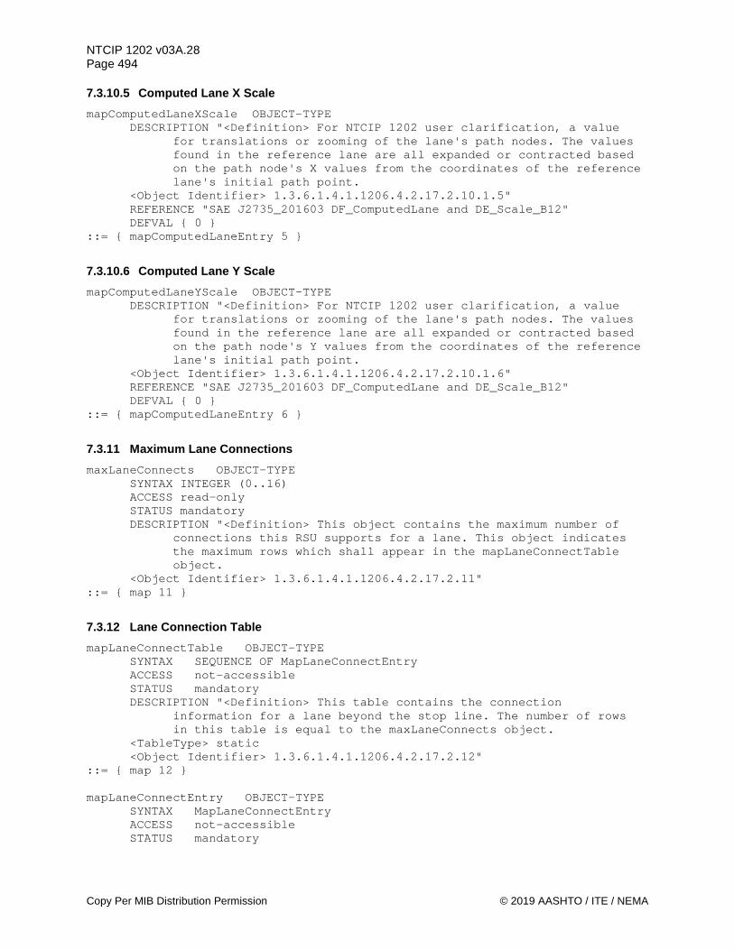
NTCIP 1202 v03A.28 Page 494
Copy Per MIB Distribution Permission © 2019 AASHTO / ITE / NEMA
7.3.10.5 Computed Lane X Scale mapComputedLaneXScale OBJECT-TYPE
DESCRIPTION "<Definition> For NTCIP 1202 user clarification, a value for translations or zooming of the lane's path nodes. The values found in the reference lane are all expanded or contracted based on the path node's X values from the coordinates of the reference lane's initial path point.
<Object Identifier> 1.3.6.1.4.1.1206.4.2.17.2.10.1.5" REFERENCE "SAE J2735_201603 DF_ComputedLane and DE_Scale_B12" DEFVAL { 0 }
::= { mapComputedLaneEntry 5 }
7.3.10.6 Computed Lane Y Scale mapComputedLaneYScale OBJECT-TYPE
DESCRIPTION "<Definition> For NTCIP 1202 user clarification, a value for translations or zooming of the lane's path nodes. The values found in the reference lane are all expanded or contracted based on the path node's Y values from the coordinates of the reference lane's initial path point.
<Object Identifier> 1.3.6.1.4.1.1206.4.2.17.2.10.1.6" REFERENCE "SAE J2735_201603 DF_ComputedLane and DE_Scale_B12" DEFVAL { 0 }
::= { mapComputedLaneEntry 6 }
7.3.11 Maximum Lane Connections maxLaneConnects OBJECT-TYPE
SYNTAX INTEGER (0..16) ACCESS read-only STATUS mandatory DESCRIPTION "<Definition> This object contains the maximum number of
connections this RSU supports for a lane. This object indicates the maximum rows which shall appear in the mapLaneConnectTable object.
<Object Identifier> 1.3.6.1.4.1.1206.4.2.17.2.11" ::= { map 11 }
7.3.12 Lane Connection Table mapLaneConnectTable OBJECT-TYPE
SYNTAX SEQUENCE OF MapLaneConnectEntry ACCESS not-accessible STATUS mandatory DESCRIPTION "<Definition> This table contains the connection
information for a lane beyond the stop line. The number of rows in this table is equal to the maxLaneConnects object.
<TableType> static <Object Identifier> 1.3.6.1.4.1.1206.4.2.17.2.12"
::= { map 12 } mapLaneConnectEntry OBJECT-TYPE
SYNTAX MapLaneConnectEntry ACCESS not-accessible STATUS mandatory

NTCIP 1202 v03A.28 Page 495
© 2019 AASHTO / ITE / NEMA Copy Per MIB Distribution Permission
DESCRIPTION "<Definition> The parameters for a specific connection for a lane.
<Object Identifier> 1.3.6.1.4.1.1206.4.2.17.2.12.1" INDEX { mapLaneIndex, mapLaneConnectIndex }
::= { mapLaneConnectTable 1 } MapLaneConnectEntry::= SEQUENCE {
mapLaneConnectIndex INTEGER, mapLaneConnectId INTEGER, mapLaneConnectManeuver INTEGER, mapLaneConnectIntersectionId INTEGER, mapLaneConnectIntersectionAuthority INTEGER, mapLaneConnectChannel INTEGER, mapLaneConnectClass INTEGER, mapLaneConnectManeuverNumber INTEGER }
7.3.12.1 Lane Connect Index mapLaneConnectIndex OBJECT-TYPE
SYNTAX INTEGER (1..16) ACCESS read-only STATUS mandatory DESCRIPTION "<Definition> The lane connection number for the objects in
this row. This value shall not exceed the maxLaneConnects object value.
<Object Identifier> 1.3.6.1.4.1.1206.4.2.17.2.12.1.1 <Unit> lane connection"
::= { mapLaneConnectEntry 1 }
7.3.12.2 Lane Connect Identifier mapLaneConnectId OBJECT-TYPE
SYNTAX INTEGER (1..255) ACCESS read-only STATUS mandatory DESCRIPTION "<Definition> The index of the lane (mapLaneIndex) that
this lane connects to. This value shall not exceed the maxLanes object value.
<Object Identifier> 1.3.6.1.4.1.1206.4.2.17.2.12.1.2" ::= { mapLaneConnectEntry 2 }
7.3.12.3 Lane Connect Maneuver mapLaneConnectManeuver OBJECT-TYPE
DESCRIPTION "<Definition> For NTCIP 1202 user clarification, represents the maneuver(s) necessary from this lane at the stop line to the connecting lane. Note: these values may be further restricted by vehicle class, local regulations or other changing conditions. If a specific attribute for the lane is true, the associated bit shall be set to (1).
<Object Identifier> 1.3.6.1.4.1.1206.4.2.17.2.12.1.3" REFERENCE "SAE J2735_201603 DF_ConnectingLane and DE_AllowedManeuvers"
::= { mapLaneConnectEntry 3 }

NTCIP 1202 v03A.28 Page 496
Copy Per MIB Distribution Permission © 2019 AASHTO / ITE / NEMA
7.3.12.4 Lane Connect Remote Intersection ID mapLaneConnectIntersectionId OBJECT-TYPE
DESCRIPTION "<Definition> For NTCIP 1202 user clarification, the identifier of the intersection if the connecting lane belongs to another intersection layout.
<Object Identifier> 1.3.6.1.4.1.1206.4.2.17.2.12.1.4" REFERENCE "SAE J2735_201603 DF_Connection and DE_IntersectionID"
::= { mapLaneConnectEntry 4 }
7.3.12.5 Lane Connect Authority Identifier mapLaneConnectIntersectionAuthority OBJECT-TYPE
DESCRIPTION "<Definition> For NTCIP 1202 user clarification, non zero if the intersection of the connecting lane belongs to another entity. A globally unique identifier assigned to an entity in a region (or country) responsible for assigning the intersectionId.
<Object Identifier> 1.3.6.1.4.1.1206.4.2.17.2.12.1.5" REFERENCE "SAE J2735_201603 DE_RoadRegulatorID"
::= { mapLaneConnectEntry 5 }
7.3.12.6 Lane Connect Channel mapLaneConnectChannel OBJECT-TYPE
DESCRIPTION "<Definition> For NTCIP 1202 user clarification, the channelNumber that this lane connecting maneuver is associated with. This value shall not exceed the maxChannels object value.
<Object Identifier> 1.3.6.1.4.1.1206.4.2.17.2.12.1.6" REFERENCE "SAE J2735_201603 DF_Connection and DE_SignalGroupID"
::= { mapLaneConnectEntry 6 }
7.3.12.7 Lane Connect Restriction Class mapLaneConnectClass OBJECT-TYPE
DESCRIPTION "<Definition> For NTCIP 1202 user clarification, the mapUserClassId to which this lane connection maneuver applies. A value of 0 indicates that lane connection maneuver applies to all vehicle types.
<Object Identifier> 1.3.6.1.4.1.1206.4.2.17.2.12.1.7" REFERENCE "SAE J2735_201603 DF_Connection and DE_RestrictionClassID" DEFVAL { 0 }
::= { mapLaneConnectEntry 7 }
7.3.12.8 Lane Connect Maneuver Number mapLaneConnectManeuverNumber OBJECT-TYPE
SYNTAX INTEGER (0..255) ACCESS read-only STATUS mandatory DESCRIPTION "<Definition> For NTCIP 1202 user clarification, the
movementManeuverId for a lane to lane connection that this mapLaneIndex and mapLaneConnectIndex is tied to. The movementManeuverIdentifier is unique within the intersection. Used to relate this lane connection to variable interval information that may be sent in the SPAT message. A value of 0 indicates undefined or not used.
<Object Identifier> 1.3.6.1.4.1.1206.4.2.17.2.12.1.8"

NTCIP 1202 v03A.28 Page 497
© 2019 AASHTO / ITE / NEMA Copy Per MIB Distribution Permission
REFERENCE "SAE J2735_201603 DF_Connection and DE_LaneConnectionID" ::= { mapLaneConnectEntry 8 }
7.3.13 Maximum Number of Speed Limits maxSpeedLimits OBJECT-TYPE
SYNTAX INTEGER (1..9) ACCESS read-only STATUS mandatory DESCRIPTION "<Definition> This object contains the maximum number of
speed limit entries this CU supports. This object indicates the maximum rows which shall appear in the mapSpeedLimitTable object.
<Object Identifier> 1.3.6.1.4.1.1206.4.2.17.2.13 <Unit> speed limits"
::= { map 13 }
7.3.14 Intersection Speed Limit Table mapSpeedLimitTable OBJECT-TYPE
SYNTAX SEQUENCE OF MapSpeedLimitEntry ACCESS not-accessible STATUS mandatory DESCRIPTION "<Definition> This table contains speed limit information.
The number of rows in this table is equal to the maxSpeedLimits object.
<TableType> static <Object Identifier> 1.3.6.1.4.1.1206.4.2.17.2.14"
::= { map 14 } mapSpeedLimitEntry OBJECT-TYPE
SYNTAX MapSpeedLimitEntry ACCESS not-accessible STATUS mandatory DESCRIPTION "<Definition> The parameters for a specific speed limit. <Object Identifier> 1.3.6.1.4.1.1206.4.2.17.2.14.1" INDEX { mapSpeedLimitIndex }
::= { mapSpeedLimitTable 1 } MapSpeedLimitEntry::= SEQUENCE {
mapSpeedLimitIndex INTEGER, mapSpeedLimitType INTEGER, mapSpeedLimit INTEGER }
7.3.14.1 Speed Limit Index mapSpeedLimitIndex OBJECT-TYPE
SYNTAX INTEGER (1..9) ACCESS read-only STATUS mandatory DESCRIPTION "<Definition> The speed limit index for objects in this
row. This value shall not exceed the maxSpeedLimits object value. <Object Identifier> 1.3.6.1.4.1.1206.4.2.17.2.14.1.1 <Unit> speed limit"
::= { mapSpeedLimitEntry 1 }

NTCIP 1202 v03A.28 Page 498
Copy Per MIB Distribution Permission © 2019 AASHTO / ITE / NEMA
7.3.14.2 Speed Limit Type mapSpeedLimitType OBJECT-TYPE
DESCRIPTION "<Definition> For NTCIP 1202 user clarification, the first enumeration (0) is unknown, the second enumeration (1) is maxSpeedInSchoolZone, etc.
<Object Identifier> 1.3.6.1.4.1.1206.4.2.17.2.14.1.2" REFERENCE "SAE J2735_201603 DE_SpeedLimitType" DEFVAL { unknown }
::= { mapSpeedLimitEntry 2 }
7.3.14.3 Speed Limit mapSpeedLimit OBJECT-TYPE
DESCRIPTION "<Definition> For NTCIP 1202 user clarification, the speed limit value.
<Object Identifier> 1.3.6.1.4.1.1206.4.2.17.2.14.1.3" REFERENCE "SAE J2735_201603 DF_RegulatorySpeedLimit and DE_Velocity" DEFVAL { 8191 }
::= { mapSpeedLimitEntry 3 }
7.3.15 Maximum User Types maxUserTypes OBJECT-TYPE
SYNTAX INTEGER(1..254) ACCESS read-only STATUS mandatory DESCRIPTION "<Definition> This object contains the maximum number of
user type entries this CU supports. This object indicates the maximum rows which shall appear in the mapUserTable object.
<Object Identifier> 1.3.6.1.4.1.1206.4.2.17.2.15 <Unit> user types"
::= { map 15 }
7.3.16 Intersection User Types Table mapUserTable OBJECT-TYPE
SYNTAX SEQUENCE OF MapUserEntry ACCESS not-accessible STATUS mandatory DESCRIPTION "<Definition> This table contains a list of user classes
that belong to a given assigned index. The number of rows in this table is equal to the maxUserTypes object.
<TableType> static <Object Identifier> 1.3.6.1.4.1.1206.4.2.17.2.16"
::= { map 16 } mapUserEntry OBJECT-TYPE
SYNTAX MapUserEntry ACCESS not-accessible STATUS mandatory DESCRIPTION "<Definition> A description of user type special movements
supported at this intersection. <Object Identifier> 1.3.6.1.4.1.1206.4.2.17.2.16.1" INDEX { mapUserIndex }
::= { mapUserTable 1 }

NTCIP 1202 v03A.28 Page 499
© 2019 AASHTO / ITE / NEMA Copy Per MIB Distribution Permission
MapUserEntry::= SEQUENCE { mapUserIndex INTEGER, mapUserClassTypes OCTET STRING }
7.3.16.1 MAP User Type Index mapUserIndex OBJECT-TYPE
SYNTAX INTEGER(1..254) ACCESS read-only STATUS mandatory DESCRIPTION "<Definition> For NTCIP 1202 user clarification, the index
of the user type for objects in this row. This value shall not exceed the maxUserTypes object value.
<Object Identifier> 1.3.6.1.4.1.1206.4.2.17.2.16.1.1" REFERENCE "SAE J2735_201603 DE_RestrictionClassID"
::= { mapUserEntry 1 }
7.3.16.2 MAP User Class Types mapUserClassTypes OBJECT-TYPE
SYNTAX OCTET STRING (SIZE (1..16)) ACCESS read-write STATUS mandatory DESCRIPTION "<Definition> For NTCIP 1202 user clarification, each octet
within the octet string represents an enumeration defined in SAE J2735_201603 DF_RestrictionAppliesTo. This object is used to indicate movements at an intersection are intended for specific traveler types or classes, as represented by SAE J2735_201603 DF_RestrictionAppliesTo.
<Object Identifier> 1.3.6.1.4.1.1206.4.2.17.2.16.1.2" REFERENCE "SAE J2735_201603 DF_RestrictionUserTypeList" DEFVAL { '00'H }
::= { mapUserEntry 2 }
7.3.17 Maximum MAP Plans maxMapPlans OBJECT-TYPE
SYNTAX INTEGER(0..8) ACCESS read-only STATUS mandatory DESCRIPTION "<Definition> This object contains the maximum number of
MAP plans this RSU supports. This object indicates the maximum rows which shall appear in the mapPlanTable object. Each MAP plan defines the lane indexes that are to be broadcasted in a MAP data message.
<Object Identifier> 1.3.6.1.4.1.1206.4.2.17.2.17 <Unit> MAP plans"
::= { map 19 }
7.3.18 MAP Plan Table mapPlanTable OBJECT-TYPE
SYNTAX SEQUENCE OF MapPlanEntry ACCESS not-accessible STATUS mandatory
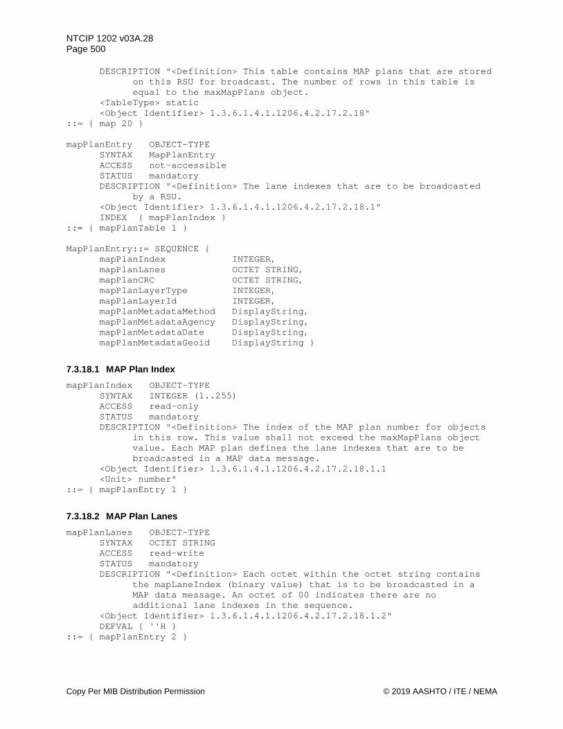
NTCIP 1202 v03A.28 Page 500
Copy Per MIB Distribution Permission © 2019 AASHTO / ITE / NEMA
DESCRIPTION "<Definition> This table contains MAP plans that are stored on this RSU for broadcast. The number of rows in this table is equal to the maxMapPlans object.
<TableType> static <Object Identifier> 1.3.6.1.4.1.1206.4.2.17.2.18"
::= { map 20 } mapPlanEntry OBJECT-TYPE
SYNTAX MapPlanEntry ACCESS not-accessible STATUS mandatory DESCRIPTION "<Definition> The lane indexes that are to be broadcasted
by a RSU. <Object Identifier> 1.3.6.1.4.1.1206.4.2.17.2.18.1" INDEX { mapPlanIndex }
::= { mapPlanTable 1 } MapPlanEntry::= SEQUENCE {
mapPlanIndex INTEGER, mapPlanLanes OCTET STRING, mapPlanCRC OCTET STRING, mapPlanLayerType INTEGER, mapPlanLayerId INTEGER, mapPlanMetadataMethod DisplayString, mapPlanMetadataAgency DisplayString, mapPlanMetadataDate DisplayString, mapPlanMetadataGeoid DisplayString }
7.3.18.1 MAP Plan Index mapPlanIndex OBJECT-TYPE
SYNTAX INTEGER (1..255) ACCESS read-only STATUS mandatory DESCRIPTION "<Definition> The index of the MAP plan number for objects
in this row. This value shall not exceed the maxMapPlans object value. Each MAP plan defines the lane indexes that are to be broadcasted in a MAP data message.
<Object Identifier> 1.3.6.1.4.1.1206.4.2.17.2.18.1.1 <Unit> number"
::= { mapPlanEntry 1 }
7.3.18.2 MAP Plan Lanes mapPlanLanes OBJECT-TYPE
SYNTAX OCTET STRING ACCESS read-write STATUS mandatory DESCRIPTION "<Definition> Each octet within the octet string contains
the mapLaneIndex (binary value) that is to be broadcasted in a MAP data message. An octet of 00 indicates there are no additional lane indexes in the sequence.
<Object Identifier> 1.3.6.1.4.1.1206.4.2.17.2.18.1.2" DEFVAL { ''H }
::= { mapPlanEntry 2 }
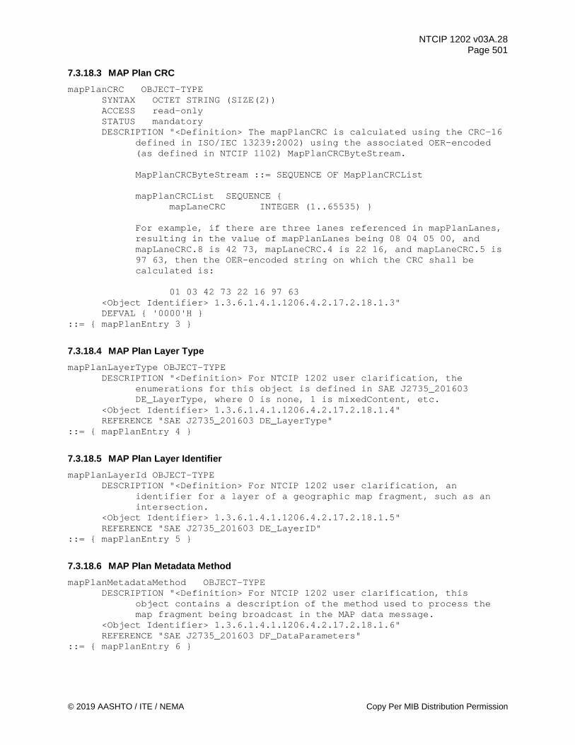
NTCIP 1202 v03A.28 Page 501
© 2019 AASHTO / ITE / NEMA Copy Per MIB Distribution Permission
7.3.18.3 MAP Plan CRC mapPlanCRC OBJECT-TYPE
SYNTAX OCTET STRING (SIZE(2)) ACCESS read-only STATUS mandatory DESCRIPTION "<Definition> The mapPlanCRC is calculated using the CRC-16
defined in ISO/IEC 13239:2002) using the associated OER-encoded (as defined in NTCIP 1102) MapPlanCRCByteStream.
MapPlanCRCByteStream ::= SEQUENCE OF MapPlanCRCList mapPlanCRCList SEQUENCE {
mapLaneCRC INTEGER (1..65535) }
For example, if there are three lanes referenced in mapPlanLanes, resulting in the value of mapPlanLanes being 08 04 05 00, and mapLaneCRC.8 is 42 73, mapLaneCRC.4 is 22 16, and mapLaneCRC.5 is 97 63, then the OER-encoded string on which the CRC shall be calculated is:
01 03 42 73 22 16 97 63
<Object Identifier> 1.3.6.1.4.1.1206.4.2.17.2.18.1.3" DEFVAL { '0000'H }
::= { mapPlanEntry 3 }
7.3.18.4 MAP Plan Layer Type mapPlanLayerType OBJECT-TYPE
DESCRIPTION "<Definition> For NTCIP 1202 user clarification, the enumerations for this object is defined in SAE J2735_201603 DE_LayerType, where 0 is none, 1 is mixedContent, etc.
<Object Identifier> 1.3.6.1.4.1.1206.4.2.17.2.18.1.4" REFERENCE "SAE J2735_201603 DE_LayerType"
::= { mapPlanEntry 4 }
7.3.18.5 MAP Plan Layer Identifier mapPlanLayerId OBJECT-TYPE
DESCRIPTION "<Definition> For NTCIP 1202 user clarification, an identifier for a layer of a geographic map fragment, such as an intersection.
<Object Identifier> 1.3.6.1.4.1.1206.4.2.17.2.18.1.5" REFERENCE "SAE J2735_201603 DE_LayerID"
::= { mapPlanEntry 5 }
7.3.18.6 MAP Plan Metadata Method mapPlanMetadataMethod OBJECT-TYPE
DESCRIPTION "<Definition> For NTCIP 1202 user clarification, this object contains a description of the method used to process the map fragment being broadcast in the MAP data message.
<Object Identifier> 1.3.6.1.4.1.1206.4.2.17.2.18.1.6" REFERENCE "SAE J2735_201603 DF_DataParameters"
::= { mapPlanEntry 6 }

NTCIP 1202 v03A.28 Page 502
Copy Per MIB Distribution Permission © 2019 AASHTO / ITE / NEMA
7.3.18.7 MAP Plan Metadata Agency mapPlanMetadataAgency OBJECT-TYPE
DESCRIPTION "<Definition> For NTCIP 1202 user clarification, this object describes the agency that developed or processed the map fragment being broadcast in the MAP data message.
<Object Identifier> 1.3.6.1.4.1.1206.4.2.17.2.18.1.7" REFERENCE "SAE J2735_201603 DF_DataParameters"
::= { mapPlanEntry 7 }
7.3.18.8 MAP Plan Metadata Date mapPlanMetadataDate OBJECT-TYPE
DESCRIPTION "<Definition> For NTCIP 1202 user clarification, this object contains the date that the map fragment being broadcast in the MAP data message was last checked.
<Object Identifier> 1.3.6.1.4.1.1206.4.2.17.2.18.1.8" REFERENCE "SAE J2735_201603 DF_DataParameters"
::= { mapPlanEntry 8 }
7.3.18.9 MAP Plan Metadata Geoid mapPlanMetadataGeoid OBJECT-TYPE
DESCRIPTION "<Object Identifier> 1.3.6.1.4.1.1206.4.2.17.2.18.1.9" REFERENCE "SAE J2735_201603 DF_DataParameters"
::= { mapPlanEntry 9 } END

NTCIP 1202 v03A.28 Page 503
© 2019 AASHTO / ITE / NEMA Copy Per RTM Distribution Permission
Annex A Requirements Traceability Matrix (RTM) [Normative]
The Requirements Traceability Matrix (RTM) links the Functional Requirements as presented in Section 3 with the corresponding Dialogs (Section 4.2) on the same (gray) line. Each Functional Requirement/Dialog relates/uses one or more groups of Objects. The Objects (also known as Data Elements) are listed to the side; the formal definition of each object is contained within Section 5. Using this table, each Functional Requirement can thus be traced in a standardized way.
Note: The INDEX objects into any of the tables are not explicitly exchanged but are used as index values for other objects that are exchanged.
The audience for this table is implementers (vendors and central system developers) and conformance testers. Additionally, other interested parties might use this table to determine how particular functions are to be implemented using the standardized dialogs, interfaces, and object definitions. To conform to a requirement, an ASC system shall implement all objects traced from that requirement; and unless otherwise indicated, shall implement all dialogs traced from the requirement. To be consistent with a requirement, an ASC system shall be able to fulfill the requirement using only objects that a conforming ASC system is required to support. Section 3 defines Supplemental Requirements, which are refining other functional requirements. These functional requirements in turn are generally traced to design elements (e.g., rather than being directly traced to design elements).
Note: Visit www.ntcip.org for information on availability of electronic copies of the RTM.
A.1 Notation [Informative]
A.1.1 Functional Requirement Columns The functional requirements are defined within Section 3 and the RTM is based upon the requirements within that Section. The section number and the functional requirement name are indicated within these columns.
A.1.2 Dialog Column The standardized dialogs are defined within Section 4 and the RTM references the traces from requirements to this dialog. The section number of the dialog is indicated within this column.

NTCIP 1202 v03A.28 Page 504
Copy Per RTM Distribution Permission © 2019 AASHTO / ITE / NEMA
A.1.3 Object Columns The objects are defined within Section 5 of NTCIP 1202 v03 and Section 2 of NTCIP 1201 v03. The RTM references the data objects that are referenced by the dialog. The section number and object name are indicated within these columns.
A.1.4 Additional Specifications The "Additional Specifications" column may (and should) be used to provide additional notes and requirements about the dialog or may be used by an implementer to provide any additional details about the implementation.
A.2 Instructions For Completing The RTM [Informative] To find the standardized design content for a functional requirement, search for the requirement identification number and functional requirement under the functional requirements columns. Next to the functional requirements column is a dialog identification number, identifying either a generic dialog (found in Annex G.3) or a specified dialog (found in Section 4.2) to be used to fulfill that requirement. To the right of the dialog identification number are the identification number and name of the data objects that are referenced or used by the dialog to fulfill the functional requirement. Object definitions specific to NTCIP 1202 v03 can be found in Section 5. If an object is defined in a different standard, that standard shall be listed first, followed by the section number where the object definition can be found. The "Additional Specifications" column provides additional notes or details about the design content.
A.3 Requirements Traceability Matrix (RTM) Table
Table 7 Requirements Traceability Matrix (RTM) Requirements Traceability Matrix (RTM)
FR ID Functional Requirement Dialog ID Object ID Object Name Additional Specifications
3.4 Architectural Requirements
3.4.1 Support Basic Communications Requirements
3.4.1.1 Retrieve Data G.1 3.4.1.2 Deliver Data G.3 3.4.1.3 Explore Data G.2 3.4.2 Support Logged Data Requirements See Annex H.1.3 3.4.3 Support Exception Reporting Requirements See Annex H.1.1.10 3.4.4 Manage Access Requirements

NTCIP 1202 v03A.28 Page 505
© 2019 AASHTO / ITE / NEMA Copy Per RTM Distribution Permission
Requirements Traceability Matrix (RTM) FR ID Functional Requirement Dialog ID Object ID Object Name Additional
Specifications 3.4.4.1 Configure Access H.2.7
1103v03 - A.8.1
communityNameAdmin
1103v03 - A.8.2
communityNamesMax
1103v03 - A.8.3
communityNameTable
1103v03 - A.8.3.1
communityNameIndex
1103v03 - A.8.3.2
communityNameUser
1103v03 - A.8.3.3
communityNameAccessMask
3.4.4.2 Determine Current Access Settings H.2.5
1103v03 - A.8.1
communityNameAdmin
1103v03 - A.8.2
communityNamesMax
1103v03 - A.8.3
communityNameTable
1103v03 - A.8.3.1
communityNameIndex
1103v03 - A.8.3.2
communityNameUser
1103v03 - A.8.3.3
communityNameAccessMask
3.5 Data Exchange and Operational Environment Requirements
3.5.1 ASC Configuration Management Requirements
3.5.1.1 Manage ASC Location Requirements

NTCIP 1202 v03A.28 Page 506
Copy Per RTM Distribution Permission © 2019 AASHTO / ITE / NEMA
Requirements Traceability Matrix (RTM) FR ID Functional Requirement Dialog ID Object ID Object Name Additional
Specifications 3.5.1.1.1 Configure ASC Location G.3
1204v03 - 5.4.1
essLatitude
1204v03 - 5.4.2
essLongitude
1204v03 - 5.5.1
essReferenceHeight Note: This height shall be measured to the base of the ASC cabinet.
3.5.1.1.2 Configure ASC Location - Antenna Offset G.3 5.4.17 ascElevationOffset 3.5.1.2 Manage Communications Requirements 3.5.1.2.1 Configure Communications Requirements 3.5.1.2.1.1 Enable/Disable Communications Port H.2.7
2103v02 - A.4.3.4 if.2.1
ifIndex
2103v02 - A.4.3.4 if.2.3
ifType
2103v02 - A.4.3.4 if.2.7
ifAdminStatus
2103v02 - A.4.3.4 if.2.8
ifOperStatus
5.4.23.2 commPortTable 5.4.23.2.1 commPortType 5.4.23.2.3 commPortEnable 3.5.1.2.1.2 Configure ASC Ethernet Ports H.2.7
2103v02 - A.4.3.4 if.2
ifTable
2103v02 - A.4.3.4 if.2.1
ifIndex
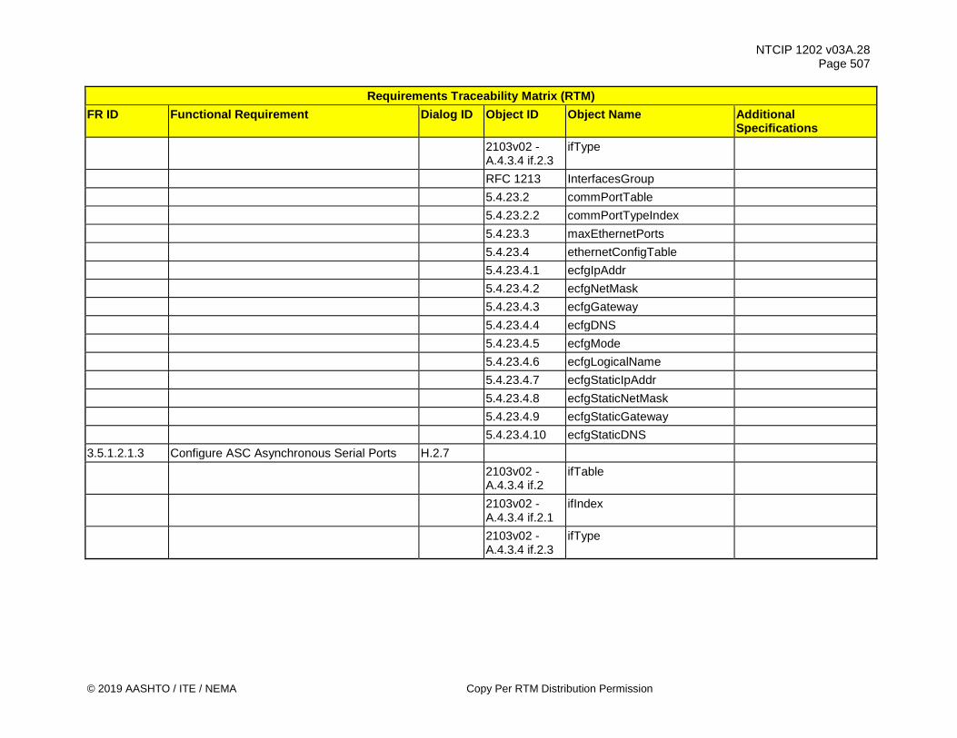
NTCIP 1202 v03A.28 Page 507
© 2019 AASHTO / ITE / NEMA Copy Per RTM Distribution Permission
Requirements Traceability Matrix (RTM) FR ID Functional Requirement Dialog ID Object ID Object Name Additional
Specifications
2103v02 - A.4.3.4 if.2.3
ifType
RFC 1213 InterfacesGroup 5.4.23.2 commPortTable 5.4.23.2.2 commPortTypeIndex 5.4.23.3 maxEthernetPorts 5.4.23.4 ethernetConfigTable 5.4.23.4.1 ecfgIpAddr 5.4.23.4.2 ecfgNetMask 5.4.23.4.3 ecfgGateway 5.4.23.4.4 ecfgDNS 5.4.23.4.5 ecfgMode 5.4.23.4.6 ecfgLogicalName 5.4.23.4.7 ecfgStaticIpAddr 5.4.23.4.8 ecfgStaticNetMask 5.4.23.4.9 ecfgStaticGateway 5.4.23.4.10 ecfgStaticDNS 3.5.1.2.1.3 Configure ASC Asynchronous Serial Ports H.2.7
2103v02 - A.4.3.4 if.2
ifTable
2103v02 - A.4.3.4 if.2.1
ifIndex
2103v02 - A.4.3.4 if.2.3
ifType

NTCIP 1202 v03A.28 Page 508
Copy Per RTM Distribution Permission © 2019 AASHTO / ITE / NEMA
Requirements Traceability Matrix (RTM) FR ID Functional Requirement Dialog ID Object ID Object Name Additional
Specifications
RFC 1317
rs232AsyncPortTable The following sections in RFC1317 are mandatory: rs232.1, rs232.2, rs232.2.1, rs232.2.2, rs232.2.5, rs232.2.6, rs232.3, rs232.3.1, rs232.3.7, rs232.3.8.
5.4.23.2 commPortTable 5.4.23.2.2 commPortTypeIndex 3.5.1.2.1.4 Configure ASC Synchronous Serial Ports H.2.7
2103v02 - A.4.3.4 if.2
ifTable
2103v02 - A.4.3.4 if.2.1
ifIndex
2103v02 - A.4.3.4 if.2.3
ifType
RFC 1317
rs232SyncPortTable The following sections in RFC1317 are mandatory: rs232.1, rs232.2, rs232.2.1, rs232.2.2, rs232.2.5, rs232.2.6, rs232.3, rs232.3.1, rs232.3.7, rs232.3.8.
5.4.23.2 commPortTable 5.4.23.2.2 commPortTypeIndex
3.5.1.2.1.5 Configure ASC Communications Protocol - Serial Ports H.2.7
2103v02 - A.4.3.4 if.2.1
ifIndex
5.4.23.2 commPortTable 5.4.23.2.4 commPortProtocolsSupported 5.4.23.2.5 commPortProtocol

NTCIP 1202 v03A.28 Page 509
© 2019 AASHTO / ITE / NEMA Copy Per RTM Distribution Permission
Requirements Traceability Matrix (RTM) FR ID Functional Requirement Dialog ID Object ID Object Name Additional
Specifications 3.5.1.2.2 Retrieve Communications Requirements
3.5.1.2.2.1 Determine Number of ASC Communications Ports G.1
5.4.23.1 maxCommPorts 3.5.1.2.3 Monitor Communications Requirements 3.5.1.2.3.1 Monitor Response Timeout - Ethernet G.1 RFC 1643 dot3 3.5.1.2.3.2 Monitor Response Timeout - Serial G.1 RFC 1317 rs232 3.5.1.2.3.3 Monitor Data Link Errors - Ethernet G.1 RFC 1643 dot3 3.5.1.2.3.4 Monitor Data Link Errors - Serial G.1 RFC 1317 rs232 3.5.1.2.3.5 Monitor Polling Timeout - Port 1 G.1 5.4.23.8 port1TimeoutFault 3.5.1.2.3.6 Monitor Polling Timeout - Serial Bus G.1 5.4.23.9 serialBus1Fault
3.5.1.2.4 Perform Communications Diagnostics Requirements
3.5.1.2.4.1 Set Communications Port to Loopback Mode H.2.7
2103v02 - A.4.3.4
ifIndex
5.4.23.2 commPortTable 5.4.23.2.6 commPortDiagnostics 3.5.1.2.4.2 Set Communications Port to Echo Mode H.2.7
2103v02 - A.4.3.4
ifIndex
5.4.23.2 commPortTable 5.4.23.2.6 commPortDiagnostics

NTCIP 1202 v03A.28 Page 510
Copy Per RTM Distribution Permission © 2019 AASHTO / ITE / NEMA
Requirements Traceability Matrix (RTM) FR ID Functional Requirement Dialog ID Object ID Object Name Additional
Specifications 3.5.1.3 Retrieve Cabinet Environment Requirements 3.5.1.3.1 Monitor Cabinet Door Status H.2.5 5.13.1 maxCabinetEnvironDevices 5.13.2 cabinetEnvironDevicesTable 5.13.2.1 cabinetEnvironDeviceNumber 5.13.2.2 cabinetEnvironDeviceType 5.13.2.3 cabinetEnvironDeviceIndex
5.13.2.4 cabinetEnvironDeviceDescription
5.13.2.5 cabinetEnvironDeviceOnStatus
5.13.2.6 cabinetEnvironDeviceErrorStatus
3.5.1.3.2 Monitor Cabinet Fan Status H.2.5 5.13.1 maxCabinetEnvironDevices 5.13.2 cabinetEnvironDevicesTable 5.13.2.1 cabinetEnvironDeviceNumber 5.13.2.2 cabinetEnvironDeviceType 5.13.2.3 cabinetEnvironDeviceIndex
5.13.2.4 cabinetEnvironDeviceDescription
5.13.2.5 cabinetEnvironDeviceOnStatus
5.13.2.6 cabinetEnvironDeviceErrorStatus
3.5.1.3.3 Monitor Cabinet Heater Status H.2.5 5.13.1 maxCabinetEnvironDevices 5.13.2 cabinetEnvironDevicesTable 5.13.2.1 cabinetEnvironDeviceNumber

NTCIP 1202 v03A.28 Page 511
© 2019 AASHTO / ITE / NEMA Copy Per RTM Distribution Permission
Requirements Traceability Matrix (RTM) FR ID Functional Requirement Dialog ID Object ID Object Name Additional
Specifications 5.13.2.2 cabinetEnvironDeviceType 5.13.2.3 cabinetEnvironDeviceIndex
5.13.2.4 cabinetEnvironDeviceDescription
5.13.2.5 cabinetEnvironDeviceOnStatus
5.13.2.6 cabinetEnvironDeviceErrorStatus
3.5.1.3.4 Monitor Cabinet Float Switch Status H.2.5 5.13.1 maxCabinetEnvironDevices 5.13.2 cabinetEnvironDevicesTable 5.13.2.1 cabinetEnvironDeviceNumber 5.13.2.2 cabinetEnvironDeviceType 5.13.2.3 cabinetEnvironDeviceIndex
5.13.2.4 cabinetEnvironDeviceDescription
5.13.2.5 cabinetEnvironDeviceOnStatus
5.13.2.6 cabinetEnvironDeviceErrorStatus
3.5.1.3.5 Monitor ASC Temperature H.2.5 5.13.3 maxCabinetTempSensors
5.13.4 cabinetTempSensorStatusTable
5.13.4.1 cabinetTempSensorIndex
5.13.4.2 cabinetTempSensorDescription
5.13.4.3 cabinetTempSensorCurrentReading
5.13.4.6 cabinetTempSensorStatus

NTCIP 1202 v03A.28 Page 512
Copy Per RTM Distribution Permission © 2019 AASHTO / ITE / NEMA
Requirements Traceability Matrix (RTM) FR ID Functional Requirement Dialog ID Object ID Object Name Additional
Specifications 3.5.1.3.6 Monitor ASC Humidity H.2.5 5.13.5 maxCabinetHumiditySensors
5.13.6 cabinetHumiditySensorStatusTable
5.13.6.1 cabinetHumiditySensorIndex
5.13.6.2 cabinetHumiditySensorDescription
5.13.6.3 cabinetHumiditySensorCurrentReading
5.13.6.5 cabinetHumiditySensorStatus 3.5.1.3.7 Configure ASC Temperature Threshold H.2.5 5.13.3 maxCabinetTempSensors
5.13.4 cabinetTempSensorStatusTable
5.13.4.1 cabinetTempSensorIndex
5.13.4.4 cabinetTempSensorHighThreshold
5.13.4.5 cabinetTempSensorLowThreshold
3.5.1.3.8 Configure ASC Humidity Thresholds H.2.5 5.13.5 maxCabinetHumiditySensors
5.13.6 cabinetHumiditySensorStatusTable
5.13.6.1 cabinetHumiditySensorIndex 5.13.6.4 cabinetHumidityThreshold 3.5.1.3.9 Configure ATC Cabinet Device LEDs G.3 5.13.9 atccLEDMode 3.5.1.4 Monitor Power Requirements 3.5.1.4.1 Determine Power Source G.1

NTCIP 1202 v03A.28 Page 513
© 2019 AASHTO / ITE / NEMA Copy Per RTM Distribution Permission
Requirements Traceability Matrix (RTM) FR ID Functional Requirement Dialog ID Object ID Object Name Additional
Specifications 5.13.7 ascPowerSource 3.5.1.4.2 Monitor AC Power Status G.1 5.13.8 ascLineVolts 3.5.1.4.3 Monitor UPS Battery Charge G.1
RFC 1628 upsEstimatedChargeRemaining
Note: support for the object only, not the complete RFC1628.
3.5.1.4.4 Monitor UPS Battery Voltage G.1
RFC 1628 upsBatteryVoltage Note: support for the
object only, not the complete RFC1628.
3.5.1.4.5 Monitor UPS Battery Current G.1
RFC 1628 upsBatteryCurrent Note: support for the
object only, not the complete RFC1628.
3.5.1.5 Manage Operational Performance Data Requirements
3.5.1.5.1 Configure Operational Performance Data Requirements
3.5.1.5.1.1 Enable/Disable Collection of Operational Performance Data H.2.7
1103v03 - A.10.1.7
recConfigTable
1103v03 - A.10.1.7.1
recConfigID
1103v03 - A.10.1.7.2
recConfigClass
1103v03 - A.10.1.7.3
recConfigMode
1103v03 - A.10.1.7.4
recConfigCompareValue

NTCIP 1202 v03A.28 Page 514
Copy Per RTM Distribution Permission © 2019 AASHTO / ITE / NEMA
Requirements Traceability Matrix (RTM) FR ID Functional Requirement Dialog ID Object ID Object Name Additional
Specifications
1103v03 - A.10.1.7.5
recConfigCompareValue2
1103v03 - A.10.1.7.6
recConfigCompareOID
1103v03 - A.10.1.7.7
recConfigRecordOID
1103v03 - A.10.1.7.8
recConfigTriggerPoint
1103v03 - A.10.1.7.9
recConfigSamplePeriod
1103v03 - A.10.1.7.10
recConfigSampleOID
1103v03 - A.10.1.7.11
recConfigNumEntries
1103v03 - A.10.1.7.12
recConfigAction
3.5.1.5.1.2 Start Collection of Operational Performance Data on Specific Date/Time H.2.7
1103v03 - A.10.1.7
recConfigTable
1103v03 - A.10.1.7.1
recConfigID
1103v03 - A.10.1.7.3
recConfigMode
1103v03 - A.10.1.7.4
recConfigCompareValue
1103v03 - A.10.1.7.5
recConfigCompareValue2
1103v03 - A.10.1.7.6
recConfigCompareOID

NTCIP 1202 v03A.28 Page 515
© 2019 AASHTO / ITE / NEMA Copy Per RTM Distribution Permission
Requirements Traceability Matrix (RTM) FR ID Functional Requirement Dialog ID Object ID Object Name Additional
Specifications
3.5.1.5.1.3 End Collection of Operational Performance Data on Specific Date/Time H.2.7
1103v03 - A.10.1.7
recConfigTable
1103v03 - A.10.1.7.1
recConfigID
1103v03 - A.10.1.7.3
recConfigMode
1103v03 - A.10.1.7.4
recConfigCompareValue
1103v03 - A.10.1.7.5
recConfigCompareValue2
1103v03 - A.10.1.7.6
recConfigCompareOID
3.5.1.5.1.4 Configure Collection of Operational Performance Data H.2.7
1103v03 - A.10.1.2
recClassTable
1103v03 - A.10.1.2.1
recClassNumber
1103v03 - A.10.1.2.2
recClassLimit
1103v03 - A.10.1.2.4
recClassDescription
1103v03 - A.10.1.7
recConfigTable
1103v03 - A.10.1.7.1
recConfigID
1103v03 - A.10.1.7.2
recConfigClass

NTCIP 1202 v03A.28 Page 516
Copy Per RTM Distribution Permission © 2019 AASHTO / ITE / NEMA
Requirements Traceability Matrix (RTM) FR ID Functional Requirement Dialog ID Object ID Object Name Additional
Specifications
1103v03 - A.10.1.7.3
recConfigMode
1103v03 - A.10.1.7.4
recConfigCompareValue
1103v03 - A.10.1.7.5
recConfigCompareValue2
1103v03 - A.10.1.7.6
recConfigCompareOID
1103v03 - A.10.1.7.7
recConfigRecordOID
1103v03 - A.10.1.7.8
recConfigTriggerPoint
1103v03 - A.10.1.7.9
recConfigSamplePeriod
1103v03 - A.10.1.7.10
recConfigSampleOID
1103v03 - A.10.1.7.11
recConfigNumEntries
1103v03 - A.10.1.7.12
recConfigAction
3.5.1.5.2 Retrieve Operational Performance Data Configuration Requirements
3.5.1.5.2.1 Determine Collection of Operational Performance Data H.2.5
1103v03 - A.10.1.3
maxRecConfigs
1103v03 - A.10.1.7
recConfigTable
1103v03 - A.10.1.7.1
recConfigID

NTCIP 1202 v03A.28 Page 517
© 2019 AASHTO / ITE / NEMA Copy Per RTM Distribution Permission
Requirements Traceability Matrix (RTM) FR ID Functional Requirement Dialog ID Object ID Object Name Additional
Specifications
1103v03 - A.10.1.7.2
recConfigClass
1103v03 - A.10.1.7.13
recConfigStatus
3.5.1.5.2.2 Determine Operational Performance Data Collection Capabilities G.1
1103v03 - A.10.1.1
maxRecClasses
1103v03 - A.10.1.3
maxRecConfigs
1103v03 - A.10.1.4
recMinSamplePeriod
1103v03 - A.10.1.5
recMaxSamplePeriod
1103v03 - A.10.1.6
recSamplePeriodResolution
1103v03 - A.10.1.8
maxRecordings
1103v03 - A.10.1.10
maxRecEntries
3.5.1.5.3 Retrieve Operational Performance Data Requirements
3.5.1.5.3.1 Monitor Operational Performance Data H.2.5
1103v03 - A.10.1.11
recEntriesTable
1103v03 - A.10.1.11.1
recEntryNumber
1103v03 - A.10.1.11.2
recSampleTime
1103v03 - A.10.1.11.3
recValue

NTCIP 1202 v03A.28 Page 518
Copy Per RTM Distribution Permission © 2019 AASHTO / ITE / NEMA
Requirements Traceability Matrix (RTM) FR ID Functional Requirement Dialog ID Object ID Object Name Additional
Specifications 3.5.1.5.3.2 Retrieve Operational Performance Data H.2.6
1103v03 - A.10.1.2
recClassTable
1103v03 - A.10.1.2.1
recClassNumber
1103v03 - A.10.1.2.5
recClassNumRecordings
1103v03 - A.10.1.2.6
recClassRecordingCounter
1103v03 - A.10.1.9
recRecordingTable
1103v03 - A.10.1.9.1
recordingClass
1103v03 - A.10.1.9.2
recordingNumber
1103v03 - A.10.1.9.3
recordingID
1103v03 - A.10.1.9.4
recordingConfigID
1103v03 - A.10.1.9.5
recordingTriggerTime
1103v03 - A.10.1.9.6
recordingStatus
1103v03 - A.10.1.9.7
recordingTriggerRecNum
1103v03 - A.10.1.9.8
recordingNumEntries
1103v03 - A.10.1.11
recEntriesTable
1103v03 - A.10.1.11.1
recEntryNumber

NTCIP 1202 v03A.28 Page 519
© 2019 AASHTO / ITE / NEMA Copy Per RTM Distribution Permission
Requirements Traceability Matrix (RTM) FR ID Functional Requirement Dialog ID Object ID Object Name Additional
Specifications
3.5.1.5.3.3 Retrieve Operational Performance Data - Time Range H.2.5
1103v03 - A.10.1.8
maxRecordings
1103v03 - A.10.1.9
recRecordingTable
1103v03 - A.10.1.9.1
recordingClass
1103v03 - A.10.1.9.2
recordingNumber
1103v03 - A.10.1.9.3
recordingID
1103v03 - A.10.1.9.7
recordingTriggerRecNum
1103v03 - A.10.1.9.8
recordingNumEntries
1103v03 - A.10.1.11
recEntriesTable
1103v03 - A.10.1.11.1
recEntryNumber
3.5.1.5.3.4 Retrieve Operational Performance Data - Event Code H.2.5
1103v03 - A.10.1.8
maxRecordings
1103v03 - A.10.1.9
recRecordingTable
1103v03 - A.10.1.9.1
recordingClass
1103v03 - A.10.1.9.2
recordingNumber
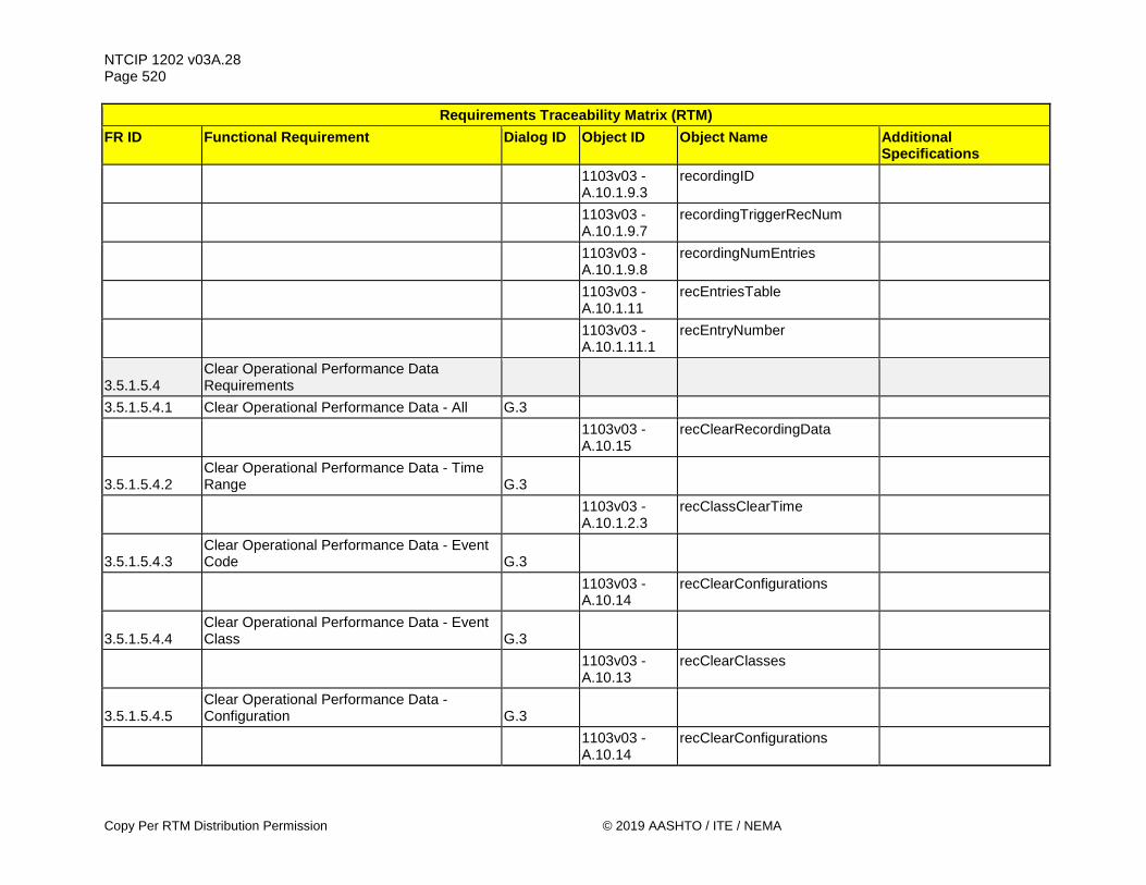
NTCIP 1202 v03A.28 Page 520
Copy Per RTM Distribution Permission © 2019 AASHTO / ITE / NEMA
Requirements Traceability Matrix (RTM) FR ID Functional Requirement Dialog ID Object ID Object Name Additional
Specifications
1103v03 - A.10.1.9.3
recordingID
1103v03 - A.10.1.9.7
recordingTriggerRecNum
1103v03 - A.10.1.9.8
recordingNumEntries
1103v03 - A.10.1.11
recEntriesTable
1103v03 - A.10.1.11.1
recEntryNumber
3.5.1.5.4 Clear Operational Performance Data Requirements
3.5.1.5.4.1 Clear Operational Performance Data - All G.3
1103v03 - A.10.15
recClearRecordingData
3.5.1.5.4.2 Clear Operational Performance Data - Time Range G.3
1103v03 - A.10.1.2.3
recClassClearTime
3.5.1.5.4.3 Clear Operational Performance Data - Event Code G.3
1103v03 - A.10.14
recClearConfigurations
3.5.1.5.4.4 Clear Operational Performance Data - Event Class G.3
1103v03 - A.10.13
recClearClasses
3.5.1.5.4.5 Clear Operational Performance Data - Configuration G.3
1103v03 - A.10.14
recClearConfigurations

NTCIP 1202 v03A.28 Page 521
© 2019 AASHTO / ITE / NEMA Copy Per RTM Distribution Permission
Requirements Traceability Matrix (RTM) FR ID Functional Requirement Dialog ID Object ID Object Name Additional
Specifications 3.5.1.6 Manage ASC Clock Requirements 3.5.1.6.1 Configure ASC Clock Source G.3 5.4.22.3 unitTimeSourceCommanded 3.5.1.6.2 Determine ASC Clock Status G.1 5.4.22.5 unitTimeSourceStatus 3.5.1.6.3 Determine Current ASC Clock Source G.1 5.4.22.4 unitTimeSourceCurrent 3.5.1.6.4 Determine Available ASC Clock Sources H.2.5 5.4.22.1 maxTimeSources 5.4.22.2 unitTimeTable 5.4.22.2.1 unitTimeIndex 5.4.22.2.2 unitTimeSourceAvailable
3.5.2 Manage Signal Operations Management Requirements
3.5.2.1 Manage Signal Configuration Requirements 3.5.2.1.1 Manage Unit Configuration Requirements 3.5.2.1.1.1 Manage Startup Requirements 3.5.2.1.1.1.1 Configure Startup All-Red Flash Mode G.3 5.4.18 unitStartUpFlashMode 3.5.2.1.1.1.2 Configure Startup Flash Time G.3 5.4.1 unitStartUpFlash
3.5.2.1.1.1.3 Enable/Disable Automatic Pedestrian Clearance Setting G.3
5.4.2 unitAutoPedestrianClear 3.5.2.1.1.2 Configure Backup Time G.3 5.4.3 unitBackupTime 3.5.2.1.1.3 Configure Backup Time - User-Defined G.3 5.4.19 unitUserDefinedBackupTime

NTCIP 1202 v03A.28 Page 522
Copy Per RTM Distribution Permission © 2019 AASHTO / ITE / NEMA
Requirements Traceability Matrix (RTM) FR ID Functional Requirement Dialog ID Object ID Object Name Additional
Specifications
3.5.2.1.1.4 Configure Backup Time - User-Defined Functions H.2.7
5.4.20 maxUserDefinedBackupTimeContent
5.4.21 unitUserDefinedBackupTimeContentTable
5.4.21.1 unitUserDefinedBackupTimeContentNumber
5.4.21.2 unitUserDefinedBackupTimeContentOID
5.4.21.3 unitUserDefinedBackupTimeContentDescription
3.5.2.1.1.5 Determine Maximum Number of Functions Supported for Backup Time G.1
5.4.20 maxUserDefinedBackupTimeContent
3.5.2.1.1.6 Configure Parameters for Creation of an Alternate Device Configuration Identifier 4.2.2
5.4.24 maxGlobalSetIds 5.4.25 globalSetIdTable 5.4.25.1 globalSetIdNumber 5.4.25.2 globalSetIdOID 3.5.2.1.2 Manage Phase Configuration Requirements 3.5.2.1.2.1 Configure Phases Requirements 3.5.2.1.2.1.1 Enable/Disable Phase 4.2.2 5.2.2 phaseTable 5.2.2.1 phaseNumber 5.2.2.21 phaseOptions Bit 0
3.5.2.1.2.1.2 Configure Vehicle Phase Minimum Green Time H.2.7

NTCIP 1202 v03A.28 Page 523
© 2019 AASHTO / ITE / NEMA Copy Per RTM Distribution Permission
Requirements Traceability Matrix (RTM) FR ID Functional Requirement Dialog ID Object ID Object Name Additional
Specifications 5.2.2 phaseTable 5.2.2.1 phaseNumber 5.2.2.4 phaseMinimumGreen 3.5.2.1.2.1.3 Configure Vehicle Phase Passage Time H.2.7 5.2.2 phaseTable 5.2.2.1 phaseNumber 5.2.2.5 phasePassage
3.5.2.1.2.1.4 Configure Vehicle Phase Maximum Green Times H.2.7
5.2.2 phaseTable 5.2.2.1 phaseNumber 5.2.2.6 phaseMaximum1 5.2.2.7 phaseMaximum2
3.5.2.1.2.1.5 Configure Vehicle Phase Third Maximum Green Times H.2.7
5.2.2 phaseTable 5.2.2.1 phaseNumber 5.2.2.24 phaseMaximum3 3.5.2.1.2.1.6 Configure Phase Yellow Time H.2.7 5.2.2 phaseTable 5.2.2.1 phaseNumber 5.2.2.8 phaseYellowChange 3.5.2.1.2.1.7 Configure Red Clearance Time H.2.7 5.2.2 phaseTable 5.2.2.1 phaseNumber 5.2.2.9 phaseRedClear 3.5.2.1.2.1.8 Configure Phase Red Revert Time H.2.7 5.2.2 phaseTable

NTCIP 1202 v03A.28 Page 524
Copy Per RTM Distribution Permission © 2019 AASHTO / ITE / NEMA
Requirements Traceability Matrix (RTM) FR ID Functional Requirement Dialog ID Object ID Object Name Additional
Specifications 5.2.2.1 phaseNumber 5.2.2.10 phaseRedRevert 3.5.2.1.2.1.9 Configure Unit Red Revert Time G.3 5.4.4 unitRedRevert 3.5.2.1.2.1.10 Configure Added Initial Time H.2.7 5.2.2 phaseTable 5.2.2.1 phaseNumber 5.2.2.11 phaseAddedInitial 3.5.2.1.2.1.11 Configure Maximum Initial Time H.2.7 5.2.2 phaseTable 5.2.2.1 phaseNumber 5.2.2.12 phaseMaximumInitial 3.5.2.1.2.1.12 Configure Time Before Reduction H.2.7 5.2.2 phaseTable 5.2.2.1 phaseNumber 5.2.2.13 phaseTimeBeforeReduction 3.5.2.1.2.1.13 Configure Phase Time to Reduce H.2.7 5.2.2 phaseTable 5.2.2.1 phaseNumber 5.2.2.15 phaseTimeToReduce 3.5.2.1.2.1.14 Configure Cars Before Reduction H.2.7 5.2.2 phaseTable 5.2.2.1 phaseNumber 5.2.2.14 phaseCarsBeforeReduction 3.5.2.1.2.1.15 Configure Phase Reduce By Time H.2.7 5.2.2 phaseTable 5.2.2.1 phaseNumber 5.2.2.16 phaseReduceBy

NTCIP 1202 v03A.28 Page 525
© 2019 AASHTO / ITE / NEMA Copy Per RTM Distribution Permission
Requirements Traceability Matrix (RTM) FR ID Functional Requirement Dialog ID Object ID Object Name Additional
Specifications 3.5.2.1.2.1.16 Configure Phase Minimum Gap Time H.2.7 5.2.2 phaseTable 5.2.2.1 phaseNumber 5.2.2.17 phaseMinimumGap 3.5.2.1.2.1.17 Configure Phase Dynamic Maximum Limit H.2.7 5.2.2 phaseTable 5.2.2.1 phaseNumber 5.2.2.18 phaseDynamicMaxLimit 3.5.2.1.2.1.18 Configure Phase Dynamic Maximum Step H.2.7 5.2.2 phaseTable 5.2.2.1 phaseNumber 5.2.2.19 phaseDynamicMaxStep 3.5.2.1.2.1.19 Configure Phase Startup Requirements 3.5.2.1.2.1.19.1
Configure Phase Startup - Initialize in a Red State 4.2.2
5.2.2 phaseTable 5.2.2.1 phaseNumber 5.2.2.20 phaseStartup phaseNotOn (2) 3.5.2.1.2.1.19.2
Configure Phase Startup - Initialize at Beginning of Min Green and Walk 4.2.2
5.2.2 phaseTable 5.2.2.1 phaseNumber 5.2.2.20 phaseStartup greenWalk (3) 3.5.2.1.2.1.19.3
Configure Phase Startup - Initialize at Beginning of Min Green 4.2.2
5.2.2 phaseTable 5.2.2.1 phaseNumber 5.2.2.20 phaseStartup greenNoWalk (4)

NTCIP 1202 v03A.28 Page 526
Copy Per RTM Distribution Permission © 2019 AASHTO / ITE / NEMA
Requirements Traceability Matrix (RTM) FR ID Functional Requirement Dialog ID Object ID Object Name Additional
Specifications 3.5.2.1.2.1.19.4
Configure Phase Startup - Initialize at Beginning of Yellow 4.2.2
5.2.2 phaseTable 5.2.2.1 phaseNumber 5.2.2.20 phaseStartup yellowChange (5) 3.5.2.1.2.1.19.5
Configure Phase Startup - Initialize at Beginning of Red Clearance 4.2.2
5.2.2 phaseTable 5.2.2.1 phaseNumber 5.2.2.20 phaseStartup redClear (6) 3.5.2.1.2.1.20 Configure Automatic Flash Entry Phase 4.2.2 5.2.2 phaseTable 5.2.2.1 phaseNumber 5.2.2.21 phaseOptions Bit 1 3.5.2.1.2.1.21 Configure Automatic Flash Exit Phase 4.2.2 5.2.2 phaseTable 5.2.2.1 phaseNumber 5.2.2.21 phaseOptions Bit 2 3.5.2.1.2.1.22 Configure Call to Non-Actuated 1 4.2.2 5.2.2 phaseTable 5.2.2.1 phaseNumber 5.2.2.21 phaseOptions Bit 3 3.5.2.1.2.1.23 Configure Call to Non-Actuated 2 4.2.2 5.2.2 phaseTable 5.2.2.1 phaseNumber 5.2.2.21 phaseOptions Bit 4 3.5.2.1.2.1.24 Configure Non-Lock Detector Memory 4.2.2 5.2.2 phaseTable

NTCIP 1202 v03A.28 Page 527
© 2019 AASHTO / ITE / NEMA Copy Per RTM Distribution Permission
Requirements Traceability Matrix (RTM) FR ID Functional Requirement Dialog ID Object ID Object Name Additional
Specifications 5.2.2.1 phaseNumber 5.2.2.21 phaseOptions Bit 5 3.5.2.1.2.1.25 Configure Minimum Vehicle Recall 4.2.2 5.2.2 phaseTable 5.2.2.1 phaseNumber 5.2.2.21 phaseOptions Bit 6 3.5.2.1.2.1.26 Configure Maximum Vehicle Recall 4.2.2 5.2.2 phaseTable 5.2.2.1 phaseNumber 5.2.2.21 phaseOptions Bit 7 3.5.2.1.2.1.27 Configure Soft Vehicle Recall 4.2.2 5.2.2 phaseTable 5.2.2.1 phaseNumber 5.2.2.21 phaseOptions Bit 9 3.5.2.1.2.1.28 Configure Dual Phase Entry 4.2.2 5.2.2 phaseTable 5.2.2.1 phaseNumber 5.2.2.21 phaseOptions Bit 10 3.5.2.1.2.1.29 Configure Simultaneous Gap Disable 4.2.2 5.2.2 phaseTable 5.2.2.1 phaseNumber 5.2.2.21 phaseOptions Bit 11 3.5.2.1.2.1.30 Configure Guaranteed Passage 4.2.2 5.2.2 phaseTable 5.2.2.1 phaseNumber 5.2.2.21 phaseOptions Bit 12 3.5.2.1.2.1.31 Configure Actuated Rest-in-Walk 4.2.2 5.2.2 phaseTable
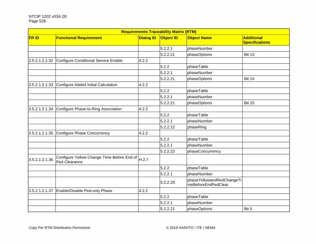
NTCIP 1202 v03A.28 Page 528
Copy Per RTM Distribution Permission © 2019 AASHTO / ITE / NEMA
Requirements Traceability Matrix (RTM) FR ID Functional Requirement Dialog ID Object ID Object Name Additional
Specifications 5.2.2.1 phaseNumber 5.2.2.21 phaseOptions Bit 13 3.5.2.1.2.1.32 Configure Conditional Service Enable 4.2.2 5.2.2 phaseTable 5.2.2.1 phaseNumber 5.2.2.21 phaseOptions Bit 14 3.5.2.1.2.1.33 Configure Added Initial Calculation 4.2.2 5.2.2 phaseTable 5.2.2.1 phaseNumber 5.2.2.21 phaseOptions Bit 15 3.5.2.1.2.1.34 Configure Phase-to-Ring Association 4.2.2 5.2.2 phaseTable 5.2.2.1 phaseNumber 5.2.2.22 phaseRing 3.5.2.1.2.1.35 Configure Phase Concurrency 4.2.2 5.2.2 phaseTable 5.2.2.1 phaseNumber 5.2.2.23 phaseConcurrency
3.5.2.1.2.1.36 Configure Yellow Change Time Before End of Ped Clearance H.2.7
5.2.2 phaseTable 5.2.2.1 phaseNumber
5.2.2.25 phaseYellowandRedChangeTimeBeforeEndPedClear
3.5.2.1.2.1.37 Enable/Disable Ped-only Phase 4.2.2 5.2.2 phaseTable 5.2.2.1 phaseNumber 5.2.2.21 phaseOptions Bit 0

NTCIP 1202 v03A.28 Page 529
© 2019 AASHTO / ITE / NEMA Copy Per RTM Distribution Permission
Requirements Traceability Matrix (RTM) FR ID Functional Requirement Dialog ID Object ID Object Name Additional
Specifications 3.5.2.1.2.1.38 Configure Pedestrian Green Time H.2.7 5.2.2 phaseTable 5.2.2.1 phaseNumber 5.2.2.2 phaseWalk 3.5.2.1.2.1.39 Configure Pedestrian Clearance Time H.2.7 5.2.2 phaseTable 5.2.2.1 phaseNumber 5.2.2.3 phasePedestrianClear 3.5.2.1.2.1.40 Configure Ped Phase Walk Recycle Time H.2.7 5.2.2 phaseTable 5.2.2.1 phaseNumber 5.2.2.26 phasePedWalkService 3.5.2.1.2.1.41 Configure Ped Phase Don't Walk Revert Time H.2.7 5.2.2 phaseTable 5.2.2.1 phaseNumber 5.2.2.27 phaseDontWalkRevert 3.5.2.1.2.1.42 Configure Non-Lock Ped Detector Memory 4.2.2 5.2.2 phaseTable 5.2.2.1 phaseNumber 5.2.2.21 phaseOptions Bit 5 3.5.2.1.2.1.43 Configure Pedestrian Recall 4.2.2 5.2.2 phaseTable 5.2.2.1 phaseNumber 5.2.2.21 phaseOptions Bit 8
3.5.2.1.2.1.44 Configure Alternate Pedestrian Clearance Time H.2.7
5.2.2 phaseTable 5.2.2.1 phaseNumber

NTCIP 1202 v03A.28 Page 530
Copy Per RTM Distribution Permission © 2019 AASHTO / ITE / NEMA
Requirements Traceability Matrix (RTM) FR ID Functional Requirement Dialog ID Object ID Object Name Additional
Specifications 5.2.2.28 phasePedAlternateClearance 3.5.2.1.2.1.45 Configure Alternate Pedestrian Walk Time H.2.7 5.2.2 phaseTable 5.2.2.1 phaseNumber 5.2.2.29 phasePedAlternateWalk 3.5.2.1.2.1.46 Configure Vehicle Phase Walk Offset Time H.2.7 5.2.2 phaseTable 5.2.2.1 phaseNumber 5.2.2.30 phasePedAdvanceWalkTime 5.2.2.31 phasePedDelayTime
3.5.2.1.2.1.47 Configure Advanced Green Warning - Associated Vehicle Phase H.2.7
See Requirement 3.5.2.1.11.1.2.3.3, Object ID 5.14.10, ascIOmapOutputFunctions - advWarnGrn (4)
5.2.2 phaseTable 5.2.2.1 phaseNumber 5.2.2.32 phaseAdvWarnGrnStartTime
3.5.2.1.2.1.48 Configure Advanced Green Warning - Start Delay Time H.2.7
5.2.2 phaseTable 5.2.2.1 phaseNumber 5.2.2.32 phaseAdvWarnGrnStartTime
3.5.2.1.2.1.49 Configure Advanced Red Warning - Associated Vehicle Phase H.2.7
See Requirement 3.5.2.1.11.1.2.3.3, Object ID 5.14.10, ascIOmapOutputFunctions - advWarnRed (5)
5.2.2 phaseTable 5.2.2.1 phaseNumber

NTCIP 1202 v03A.28 Page 531
© 2019 AASHTO / ITE / NEMA Copy Per RTM Distribution Permission
Requirements Traceability Matrix (RTM) FR ID Functional Requirement Dialog ID Object ID Object Name Additional
Specifications 5.2.2.33 phaseAdvWarnRedStartTime
3.5.2.1.2.1.50 Configure Red Indication Advanced Warning - Start Delay Time H.2.7
5.2.2 phaseTable 5.2.2.1 phaseNumber 5.2.2.33 phaseAdvWarnRedStartTime
3.5.2.1.2.1.51 Configure Flashing Yellow Arrow Associated Vehicle Phase H.2.7
5.10.2 overlapTable 5.10.2.1 overlapNumber 5.10.2.2 overlapType 5.10.2.3 overlapIncludedPhases 5.10.2.4 overlapModifierPhases
3.5.2.1.2.1.52 Configure Flashing Red Arrow Associated Vehicle Phase H.2.7
5.10.2 overlapTable 5.10.2.1 overlapNumber 5.10.2.2 overlapType 5.10.2.3 overlapIncludedPhases 5.10.2.4 overlapModifierPhases
3.5.2.1.2.1.53 Configure Bicycle Phase Minimum Green Time H.2.7
5.2.2 phaseTable 5.2.2.1 phaseNumber 5.2.2.4 phaseMinimumGreen 3.5.2.1.2.1.54 Configure Bicycle Phase Yellow Time H.2.7 5.2.2 phaseTable 5.2.2.1 phaseNumber 5.2.2.8 phaseYellowChange

NTCIP 1202 v03A.28 Page 532
Copy Per RTM Distribution Permission © 2019 AASHTO / ITE / NEMA
Requirements Traceability Matrix (RTM) FR ID Functional Requirement Dialog ID Object ID Object Name Additional
Specifications 3.5.2.1.2.1.55 Configure Bicycle Phase Red Clearance Time H.2.7 5.2.2 phaseTable 5.2.2.1 phaseNumber 5.2.2.9 phaseRedClear 3.5.2.1.2.1.56 Configure Bicycle Phase Red Revert Time H.2.7 5.2.2 phaseTable 5.2.2.1 phaseNumber 5.2.2.10 phaseRedRevert 3.5.2.1.2.1.57 Enable/Disable Bicycle Phase 4.2.2 5.2.2 phaseTable 5.2.2.1 phaseNumber 5.2.2.21 phaseOptions Bit 0 3.5.2.1.2.1.58 Configure Non-Lock Bicycle Detector Memory 4.2.2 5.2.2 phaseTable 5.2.2.1 phaseNumber 5.2.2.21 phaseOptions Bit 5 3.5.2.1.2.1.59 Configure Bicycle Phase Recall 4.2.2 5.2.2 phaseTable 5.2.2.1 phaseNumber 5.2.2.21 phaseOptions Bit 6 3.5.2.1.2.1.60 Configure Soft Bicycle Phase Recall 4.2.2 5.2.2 phaseTable 5.2.2.1 phaseNumber 5.2.2.21 phaseOptions Bit 9 3.5.2.1.2.1.61 Configure Bicycle Phase-to-Ring Association 4.2.2 5.2.2 phaseTable 5.2.2.1 phaseNumber 5.2.2.22 phaseRing
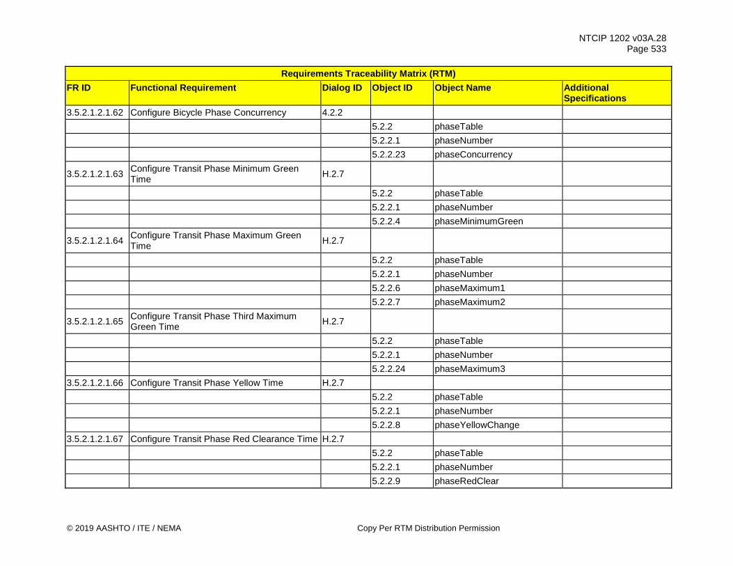
NTCIP 1202 v03A.28 Page 533
© 2019 AASHTO / ITE / NEMA Copy Per RTM Distribution Permission
Requirements Traceability Matrix (RTM) FR ID Functional Requirement Dialog ID Object ID Object Name Additional
Specifications 3.5.2.1.2.1.62 Configure Bicycle Phase Concurrency 4.2.2 5.2.2 phaseTable 5.2.2.1 phaseNumber 5.2.2.23 phaseConcurrency
3.5.2.1.2.1.63 Configure Transit Phase Minimum Green Time H.2.7
5.2.2 phaseTable 5.2.2.1 phaseNumber 5.2.2.4 phaseMinimumGreen
3.5.2.1.2.1.64 Configure Transit Phase Maximum Green Time H.2.7
5.2.2 phaseTable 5.2.2.1 phaseNumber 5.2.2.6 phaseMaximum1 5.2.2.7 phaseMaximum2
3.5.2.1.2.1.65 Configure Transit Phase Third Maximum Green Time H.2.7
5.2.2 phaseTable 5.2.2.1 phaseNumber 5.2.2.24 phaseMaximum3 3.5.2.1.2.1.66 Configure Transit Phase Yellow Time H.2.7 5.2.2 phaseTable 5.2.2.1 phaseNumber 5.2.2.8 phaseYellowChange 3.5.2.1.2.1.67 Configure Transit Phase Red Clearance Time H.2.7 5.2.2 phaseTable 5.2.2.1 phaseNumber 5.2.2.9 phaseRedClear

NTCIP 1202 v03A.28 Page 534
Copy Per RTM Distribution Permission © 2019 AASHTO / ITE / NEMA
Requirements Traceability Matrix (RTM) FR ID Functional Requirement Dialog ID Object ID Object Name Additional
Specifications 3.5.2.1.2.1.68 Configure Transit Phase Red Revert Time H.2.7 5.2.2 phaseTable 5.2.2.1 phaseNumber 5.2.2.10 phaseRedRevert 3.5.2.1.2.1.69 Configure Transit Phase Added Initial Time H.2.7 5.2.2 phaseTable 5.2.2.1 phaseNumber 5.2.2.11 phaseAddedInitial
3.5.2.1.2.1.70 Configure Transit Phase Maximum Initial Time H.2.7
5.2.2 phaseTable 5.2.2.1 phaseNumber 5.2.2.12 phaseMaximumInitial 3.5.2.1.2.1.71 Enable/Disable Transit Phase 4.2.2 5.2.2 phaseTable 5.2.2.1 phaseNumber 5.2.2.21 phaseOptions Bit 0 3.5.2.1.2.1.72 Configure Non-Lock Transit Detector Memory 4.2.2 5.2.2 phaseTable 5.2.2.1 phaseNumber 5.2.2.21 phaseOptions Bit 5 3.5.2.1.2.1.73 Configure Transit Phase Recall 4.2.2 5.2.2 phaseTable 5.2.2.1 phaseNumber 5.2.2.21 phaseOptions Bit 6 3.5.2.1.2.1.74 Configure Soft Transit Phase Recall 4.2.2 5.2.2 phaseTable 5.2.2.1 phaseNumber

NTCIP 1202 v03A.28 Page 535
© 2019 AASHTO / ITE / NEMA Copy Per RTM Distribution Permission
Requirements Traceability Matrix (RTM) FR ID Functional Requirement Dialog ID Object ID Object Name Additional
Specifications 5.2.2.21 phaseOptions Bit 9 3.5.2.1.2.1.75 Configure Dual Transit Phase Entry 4.2.2 5.2.2 phaseTable 5.2.2.1 phaseNumber 5.2.2.21 phaseOptions Bit 10 3.5.2.1.2.1.76 Configure Transit Phase-to-Ring Association 4.2.2 5.2.2 phaseTable 5.2.2.1 phaseNumber 5.2.2.22 phaseRing 3.5.2.1.2.1.77 Configure Transit Phase Concurrency 4.2.2 5.2.2 phaseTable 5.2.2.1 phaseNumber 5.2.2.23 phaseConcurrency 3.5.2.1.2.1.78 Enable/Disable Vehicle Phase Omit H.2.7 5.2.5 phaseControlGroupTable 5.2.5.1 phaseControlGroupNumber
5.2.5.2 phaseControlGroupPhaseOmit
3.5.2.1.2.1.79 Enable/Disable Vehicle Phase Omit during Transition H.2.7
5.5.9 splitTable 5.5.9.1 splitNumber 5.5.9.2 splitPhase 5.5.9.6 splitOptions Bit 0 3.5.2.1.2.1.80 Enable/Disable Ped-only Phase Omit H.2.7 5.2.5 phaseControlGroupTable 5.2.5.1 phaseControlGroupNumber 5.2.5.3 phaseControlGroupPedOmit

NTCIP 1202 v03A.28 Page 536
Copy Per RTM Distribution Permission © 2019 AASHTO / ITE / NEMA
Requirements Traceability Matrix (RTM) FR ID Functional Requirement Dialog ID Object ID Object Name Additional
Specifications
3.5.2.1.2.1.81 Enable/Disable Ped-only Phase Omit during Transition H.2.7
5.5.9 splitTable 5.5.9.1 splitNumber 5.5.9.2 splitPhase 5.5.9.6 splitOptions Bit 0 3.5.2.1.2.1.82 Enable/Disable Bicycle-only Phase Omit H.2.7 5.2.5 phaseControlGroupTable 5.2.5.1 phaseControlGroupNumber
5.2.5.2 phaseControlGroupPhaseOmit
3.5.2.1.2.1.83 Enable/Disable Bicycle-only Phase Omit during Transition H.2.7
5.5.9 splitTable 5.5.9.1 splitNumber 5.5.9.2 splitPhase 5.5.9.6 splitOptions Bit 0 3.5.2.1.2.1.84 Enable/Disable Transit Phase Omit H.2.7 5.2.5 phaseControlGroupTable 5.2.5.1 phaseControlGroupNumber
5.2.5.2 phaseControlGroupPhaseOmit
3.5.2.1.2.1.85 Enable/Disable Transit Phase Omit during Transition H.2.7
5.5.9 splitTable 5.5.9.1 splitNumber 5.5.9.2 splitPhase 5.5.9.6 splitOptions Bit 0
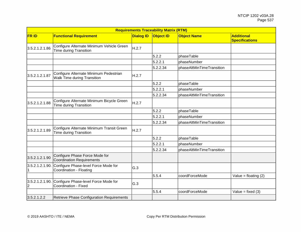
NTCIP 1202 v03A.28 Page 537
© 2019 AASHTO / ITE / NEMA Copy Per RTM Distribution Permission
Requirements Traceability Matrix (RTM) FR ID Functional Requirement Dialog ID Object ID Object Name Additional
Specifications
3.5.2.1.2.1.86 Configure Alternate Minimum Vehicle Green Time during Transition H.2.7
5.2.2 phaseTable 5.2.2.1 phaseNumber 5.2.2.34 phaseAltMinTimeTransition
3.5.2.1.2.1.87 Configure Alternate Minimum Pedestrian Walk Time during Transition H.2.7
5.2.2 phaseTable 5.2.2.1 phaseNumber 5.2.2.34 phaseAltMinTimeTransition
3.5.2.1.2.1.88 Configure Alternate Minimum Bicycle Green Time during Transition H.2.7
5.2.2 phaseTable 5.2.2.1 phaseNumber 5.2.2.34 phaseAltMinTimeTransition
3.5.2.1.2.1.89 Configure Alternate Minimum Transit Green Time during Transition H.2.7
5.2.2 phaseTable 5.2.2.1 phaseNumber 5.2.2.34 phaseAltMinTimeTransition
3.5.2.1.2.1.90 Configure Phase Force Mode for Coordination Requirements
3.5.2.1.2.1.90.1
Configure Phase-level Force Mode for Coordination - Floating G.3
5.5.4 coordForceMode Value = floating (2) 3.5.2.1.2.1.90.2
Configure Phase-level Force Mode for Coordination - Fixed G.3
5.5.4 coordForceMode Value = fixed (3) 3.5.2.1.2.2 Retrieve Phase Configuration Requirements

NTCIP 1202 v03A.28 Page 538
Copy Per RTM Distribution Permission © 2019 AASHTO / ITE / NEMA
Requirements Traceability Matrix (RTM) FR ID Functional Requirement Dialog ID Object ID Object Name Additional
Specifications 3.5.2.1.2.2.1 Determine Maximum Number of Phases G.1 5.2.1 maxPhases
3.5.2.1.3 Manage Coordination Configuration Requirements
3.5.2.1.3.1 Configure Operational Mode for Coordination Requirements
3.5.2.1.3.1.1 Configure Operational Mode for Coordination - Automatic G.3
5.5.1 coordOperationalMode Value = 0
3.5.2.1.3.1.2 Configure Operational Mode for Coordination - Manual Pattern G.3
5.5.1 coordOperationalMode
3.5.2.1.3.1.3 Configure Operational Mode for Coordination - Manual Free G.3
5.5.1 coordOperationalMode Value = 254
3.5.2.1.3.1.4 Configure Operational Mode for Coordination - Manual Flash G.3
5.5.1 coordOperationalMode Value = 255
3.5.2.1.3.2 Configure Correction Mode for Coordination Requirements
3.5.2.1.3.2.1 Configure Correction Mode for Coordination - Dwell G.3
5.5.2 coordCorrectionMode Value = dwell (2)
3.5.2.1.3.2.2 Configure Correction Mode for Coordination - Shortway G.3
5.5.2 coordCorrectionMode Value = shortway (3)
3.5.2.1.3.2.3 Configure Correction Mode for Coordination - AddOnly G.3
5.5.2 coordCorrectionMode Value = addOnly (4)
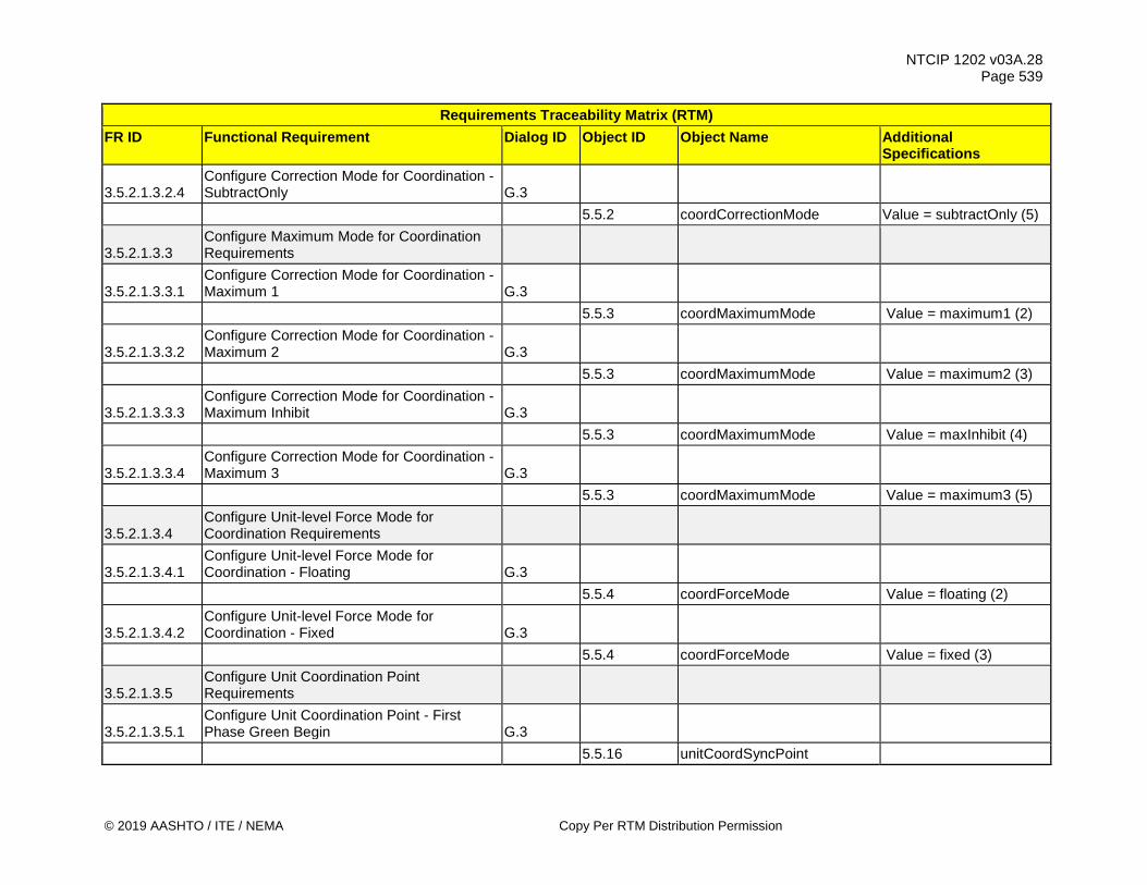
NTCIP 1202 v03A.28 Page 539
© 2019 AASHTO / ITE / NEMA Copy Per RTM Distribution Permission
Requirements Traceability Matrix (RTM) FR ID Functional Requirement Dialog ID Object ID Object Name Additional
Specifications
3.5.2.1.3.2.4 Configure Correction Mode for Coordination - SubtractOnly G.3
5.5.2 coordCorrectionMode Value = subtractOnly (5)
3.5.2.1.3.3 Configure Maximum Mode for Coordination Requirements
3.5.2.1.3.3.1 Configure Correction Mode for Coordination - Maximum 1 G.3
5.5.3 coordMaximumMode Value = maximum1 (2)
3.5.2.1.3.3.2 Configure Correction Mode for Coordination - Maximum 2 G.3
5.5.3 coordMaximumMode Value = maximum2 (3)
3.5.2.1.3.3.3 Configure Correction Mode for Coordination - Maximum Inhibit G.3
5.5.3 coordMaximumMode Value = maxInhibit (4)
3.5.2.1.3.3.4 Configure Correction Mode for Coordination - Maximum 3 G.3
5.5.3 coordMaximumMode Value = maximum3 (5)
3.5.2.1.3.4 Configure Unit-level Force Mode for Coordination Requirements
3.5.2.1.3.4.1 Configure Unit-level Force Mode for Coordination - Floating G.3
5.5.4 coordForceMode Value = floating (2)
3.5.2.1.3.4.2 Configure Unit-level Force Mode for Coordination - Fixed G.3
5.5.4 coordForceMode Value = fixed (3)
3.5.2.1.3.5 Configure Unit Coordination Point Requirements
3.5.2.1.3.5.1 Configure Unit Coordination Point - First Phase Green Begin G.3
5.5.16 unitCoordSyncPoint

NTCIP 1202 v03A.28 Page 540
Copy Per RTM Distribution Permission © 2019 AASHTO / ITE / NEMA
Requirements Traceability Matrix (RTM) FR ID Functional Requirement Dialog ID Object ID Object Name Additional
Specifications
3.5.2.1.3.5.2 Configure Unit Coordination Point - Last Phase Green Begin G.3
5.5.16 unitCoordSyncPoint
3.5.2.1.3.5.3 Configure Unit Coordination Point - First Phase Green End G.3
5.5.16 unitCoordSyncPoint
3.5.2.1.3.5.4 Configure Unit Coordination Point - Last Phase Green End G.3
5.5.16 unitCoordSyncPoint
3.5.2.1.3.5.5 Configure Unit Coordination Point - First Phase Yellow End G.3
5.5.16 unitCoordSyncPoint
3.5.2.1.3.5.6 Configure Unit Coordination Point - Last Phase Yellow End G.3
5.5.16 unitCoordSyncPoint 3.5.2.1.3.6 Configure Coordination Point Requirements
3.5.2.1.3.6.1 Configure Coordination Point - First Phase Green Begin H.2.7
5.5.7 patternTable 5.5.7.1 patternNumber
5.5.7.6
patternCoordSyncPoint Value = firstCoordPhsGrnBegin (2)
3.5.2.1.3.6.2 Configure Coordination Point - Last Phase Green Begin H.2.7
5.5.7 patternTable 5.5.7.1 patternNumber
5.5.7.6
patternCoordSyncPoint Value = lastCoordPhsGrnBegin (3)

NTCIP 1202 v03A.28 Page 541
© 2019 AASHTO / ITE / NEMA Copy Per RTM Distribution Permission
Requirements Traceability Matrix (RTM) FR ID Functional Requirement Dialog ID Object ID Object Name Additional
Specifications
3.5.2.1.3.6.3 Configure Coordination Point - First Phase Green End H.2.7
5.5.7 patternTable 5.5.7.1 patternNumber
5.5.7.6 patternCoordSyncPoint Value =
firstCoordPhsGrnEnd (4)
3.5.2.1.3.6.4 Configure Coordination Point - Last Phase Green End H.2.7
5.5.7 patternTable 5.5.7.1 patternNumber
5.5.7.6 patternCoordSyncPoint Value =
lastCoordPhsGrnEnd (5)
3.5.2.1.3.6.5 Configure Coordination Point - First Phase Yellow End H.2.7
5.5.7 patternTable 5.5.7.1 patternNumber
5.5.7.6 patternCoordSyncPoint Value =
firstCoordPhsYelEnd (6)
3.5.2.1.3.6.6 Configure Coordination Point - Last Phase Yellow End H.2.7
5.5.7 patternTable 5.5.7.1 patternNumber
5.5.7.6 patternCoordSyncPoint Value =
lastCoordPhsYelEnd (6) 3.5.2.1.3.7 Configure Omit Phases During Transitions H.2.7 5.2.2 phaseTable 5.2.2.1 phaseNumber 5.2.2.34 phaseAltMinTimeTransition
3.5.2.1.3.8 Configure Minimum Green Times During Transitions H.2.7

NTCIP 1202 v03A.28 Page 542
Copy Per RTM Distribution Permission © 2019 AASHTO / ITE / NEMA
Requirements Traceability Matrix (RTM) FR ID Functional Requirement Dialog ID Object ID Object Name Additional
Specifications 5.2.2 phaseTable 5.2.2.1 phaseNumber 5.2.2.34 phaseAltMinTimeTransition
3.5.2.1.3.9 Configure Minimum Pedestrian Times During Transitions H.2.7
5.2.2 phaseTable 5.2.2.1 phaseNumber 5.2.2.34 phaseAltMinTimeTransition
3.5.2.1.3.10 Configure Transit Maximum Mode for Coordination Requirements
3.5.2.1.3.10.1 Configure Transit Correction Mode for Coordination - Maximum 1 G.3
5.5.3 coordMaximumMode Value = maximum1 (2)
3.5.2.1.3.10.2 Configure Transit Correction Mode for Coordination - Maximum 2 G.3
5.5.3 coordMaximumMode Value = maximum2 (3)
3.5.2.1.3.10.3 Configure Transit Correction Mode for Coordination - MaxInhibit G.3
5.5.3 coordMaximumMode Value = maxInhibit (4)
3.5.2.1.3.10.4 Configure Transit Correction Mode for Coordination - Maximum 3 G.3
5.5.3 coordMaximumMode Value = maximum3 (5)
3.5.2.1.4 Manage Phase-Based Timing Patterns Requirements
3.5.2.1.4.1 Configure Phase-Based Timing Patterns Requirements
3.5.2.1.4.1.1 Configure Pattern Cycle Time H.2.7 5.5.6 patternTableType 5.5.7 patternTable

NTCIP 1202 v03A.28 Page 543
© 2019 AASHTO / ITE / NEMA Copy Per RTM Distribution Permission
Requirements Traceability Matrix (RTM) FR ID Functional Requirement Dialog ID Object ID Object Name Additional
Specifications 5.5.7.1 patternNumber 5.5.7.2 patternCycleTime 3.5.2.1.4.1.2 Configure Pattern Offset Time H.2.7 5.5.6 patternTableType 5.5.7 patternTable 5.5.7.1 patternNumber 5.5.7.3 patternOffsetTime 3.5.2.1.4.1.3 Configure Pattern Split Association H.2.7 5.5.6 patternTableType 5.5.7 patternTable 5.5.7.1 patternNumber 5.5.7.4 patternSplitNumber 3.5.2.1.4.1.4 Configure Pattern Sequence Association H.2.7 5.5.6 patternTableType 5.5.7 patternTable 5.5.7.1 patternNumber 5.5.7.5 patternSequenceNumber 3.5.2.1.4.1.5 Configure Pattern Maximum Mode H.2.7 5.5.6 patternTableType 5.5.7 patternTable 5.5.7.1 patternNumber 5.5.7.7 patternOptions Bits 0, 1, 2
3.5.2.1.4.2 Retrieve Phase-Based Timing Patterns Requirements
3.5.2.1.4.2.1 Determine Maximum Number of Phase-based Timing Pattern G.1
5.5.5 maxPatterns 3.5.2.1.4.2.2 Determine Phase-based Timing Pattern Type G.1

NTCIP 1202 v03A.28 Page 544
Copy Per RTM Distribution Permission © 2019 AASHTO / ITE / NEMA
Requirements Traceability Matrix (RTM) FR ID Functional Requirement Dialog ID Object ID Object Name Additional
Specifications 5.5.6 patternTableType 3.5.2.1.5 Manage Splits Configuration Requirements 3.5.2.1.5.1 Configure Split Requirements 3.5.2.1.5.1.1 Configure Phase Split Time H.2.7 5.5.9 splitTable 5.5.9.1 splitNumber 5.5.9.2 splitPhase 5.5.9.3 splitTime 3.5.2.1.5.1.2 Configure Phase Split Mode Requirements 3.5.2.1.5.1.2.1 Configure Phase Split Mode - None H.2.7 5.5.9 splitTable 5.5.9.1 splitNumber 5.5.9.4 splitMode Value = 2
3.5.2.1.5.1.2.2 Configure Phase Split Mode - Minimum Vehicle Recall H.2.7
5.5.9 splitTable 5.5.9.1 splitNumber 5.5.9.4 splitMode Value = 3
3.5.2.1.5.1.2.3 Configure Phase Split Mode - Maximum Vehicle Recall H.2.7
5.5.9 splitTable 5.5.9.1 splitNumber 5.5.9.4 splitMode Value = 4
3.5.2.1.5.1.2.4 Configure Phase Split Mode - Pedestrian Recall H.2.7
5.5.9 splitTable 5.5.9.1 splitNumber 5.5.9.4 splitMode Value = 5

NTCIP 1202 v03A.28 Page 545
© 2019 AASHTO / ITE / NEMA Copy Per RTM Distribution Permission
Requirements Traceability Matrix (RTM) FR ID Functional Requirement Dialog ID Object ID Object Name Additional
Specifications
3.5.2.1.5.1.2.5 Configure Phase Split Mode - Maximum Vehicle and Pedestrian Recall H.2.7
5.5.9 splitTable 5.5.9.1 splitNumber 5.5.9.4 splitMode Value = 6 3.5.2.1.5.1.2.6 Configure Phase Split Mode - Phase Omit H.2.7 5.5.9 splitTable 5.5.9.1 splitNumber 5.5.9.4 splitMode Value = 7 3.5.2.1.5.1.2.7 Configure Phase Split Mode - Bicycle Recall H.2.7 5.5.9 splitTable 5.5.9.1 splitNumber 5.5.9.4 splitMode Value = 4 3.5.2.1.5.1.2.8 Configure Phase Split Mode - Transit Recall H.2.7 5.5.9 splitTable 5.5.9.1 splitNumber 5.5.9.4 splitMode Value = 4 3.5.2.1.5.1.2.9 Configure Phase Split Mode - Non-Actuated H.2.7 5.5.9 splitTable 5.5.9.1 splitNumber 5.5.9.4 splitMode Value = 8 3.5.2.1.5.1.3 Configure Split Coordination Phase H.2.7 5.5.9 splitTable 5.5.9.1 splitNumber 5.5.9.5 splitCoordPhase 3.5.2.1.5.1.4 Configure Pre-timed Split H.2.7 5.5.9 splitTable 5.5.9.1 splitNumber

NTCIP 1202 v03A.28 Page 546
Copy Per RTM Distribution Permission © 2019 AASHTO / ITE / NEMA
Requirements Traceability Matrix (RTM) FR ID Functional Requirement Dialog ID Object ID Object Name Additional
Specifications 5.5.9.3 splitTime 3.5.2.1.5.2 Retrieve Split Requirements 3.5.2.1.5.2.1 Determine Maximum Number of Phase Splits G.1 5.5.8 maxSplits 3.5.2.1.6 Manage Ring Configuration Requirements 3.5.2.1.6.1 Configure Ring Requirements 3.5.2.1.6.1.1 Configure Sequence Data 4.2.2 5.8.3 sequenceTable 5.8.3.1 sequenceNumber 5.8.3.2 sequenceRingNumber 5.8.3.3 sequenceData 3.5.2.1.6.2 Retrieve Rings Requirements 3.5.2.1.6.2.1 Determine Maximum Number of Rings G.1 5.8.1 maxRings 3.5.2.1.6.2.2 Determine Maximum Number of Sequences G.1 5.8.2 maxSequences 3.5.2.1.7 Manage Channel Configuration Requirements 3.5.2.1.7.1 Configure Channel Requirements 3.5.2.1.7.1.1 Configure Channel Control Source H.2.7 5.9.2 channelTable 5.9.2.1 channelNumber 5.9.2.2 channelControlSource
3.5.2.1.7.1.2 Configure Channel Control Type Requirements
3.5.2.1.7.1.2.1 Configure Channel Control Type - Vehicle Phase H.2.7
5.9.2 channelTable 5.9.2.1 channelNumber
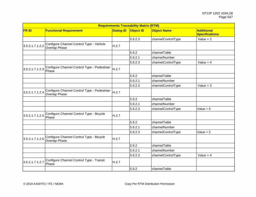
NTCIP 1202 v03A.28 Page 547
© 2019 AASHTO / ITE / NEMA Copy Per RTM Distribution Permission
Requirements Traceability Matrix (RTM) FR ID Functional Requirement Dialog ID Object ID Object Name Additional
Specifications 5.9.2.3 channelControlType Value = 2
3.5.2.1.7.1.2.2 Configure Channel Control Type - Vehicle Overlap Phase H.2.7
5.9.2 channelTable 5.9.2.1 channelNumber 5.9.2.3 channelControlType Value = 4
3.5.2.1.7.1.2.3 Configure Channel Control Type - Pedestrian Phase H.2.7
5.9.2 channelTable 5.9.2.1 channelNumber 5.9.2.3 channelControlType Value = 3
3.5.2.1.7.1.2.4 Configure Channel Control Type - Pedestrian Overlap Phase H.2.7
5.9.2 channelTable 5.9.2.1 channelNumber 5.9.2.3 channelControlType Value = 5
3.5.2.1.7.1.2.5 Configure Channel Control Type - Bicycle Phase H.2.7
5.9.2 channelTable 5.9.2.1 channelNumber 5.9.2.3 channelControlType Value = 2
3.5.2.1.7.1.2.6 Configure Channel Control Type - Bicycle Overlap Phase H.2.7
5.9.2 channelTable 5.9.2.1 channelNumber 5.9.2.3 channelControlType Value = 4
3.5.2.1.7.1.2.7 Configure Channel Control Type - Transit Phase H.2.7
5.9.2 channelTable

NTCIP 1202 v03A.28 Page 548
Copy Per RTM Distribution Permission © 2019 AASHTO / ITE / NEMA
Requirements Traceability Matrix (RTM) FR ID Functional Requirement Dialog ID Object ID Object Name Additional
Specifications 5.9.2.1 channelNumber 5.9.2.3 channelControlType Value = 2
3.5.2.1.7.1.2.8 Configure Channel Control Type - Transit Overlap Phase H.2.7
5.9.2 channelTable 5.9.2.1 channelNumber 5.9.2.3 channelControlType Value = 4
3.5.2.1.7.1.2.9 Configure Channel Control Type - Queue Jump Phase H.2.7
5.9.2 channelTable 5.9.2.1 channelNumber 5.9.2.3 channelControlType Value = 6
3.5.2.1.7.1.3 Configure Channel Flash Enable/Disable Requirements
3.5.2.1.7.1.3.1 Enable/Disable Channel Flash - Yellow H.2.7 5.9.2 channelTable 5.9.2.1 channelNumber 5.9.2.4 channelFlash Bit 1 3.5.2.1.7.1.3.2 Enable/Disable Channel Flash - Red H.2.7 5.9.2 channelTable 5.9.2.1 channelNumber 5.9.2.4 channelFlash Bit 2
3.5.2.1.7.1.3.3 Enable/Disable Channel Flash - Alternate Half Hertz H.2.7
5.9.2 channelTable 5.9.2.1 channelNumber 5.9.2.4 channelFlash Bit 3
3.5.2.1.7.1.4 Configure Channel Dim Enable/Disable Requirements

NTCIP 1202 v03A.28 Page 549
© 2019 AASHTO / ITE / NEMA Copy Per RTM Distribution Permission
Requirements Traceability Matrix (RTM) FR ID Functional Requirement Dialog ID Object ID Object Name Additional
Specifications 3.5.2.1.7.1.4.1 Enable/Disable Channel Dim - Green H.2.7 5.9.2 channelTable 5.9.2.1 channelNumber 5.9.2.5 channelDim Bit 0 3.5.2.1.7.1.4.2 Enable/Disable Channel Dim - Yellow H.2.7 5.9.2 channelTable 5.9.2.1 channelNumber 5.9.2.5 channelDim Bit 1 3.5.2.1.7.1.4.3 Enable/Disable Channel Dim - Red H.2.7 5.9.2 channelTable 5.9.2.1 channelNumber 5.9.2.5 channelDim Bit 2
3.5.2.1.7.1.4.4 Enable/Disable Channel Dim - Alternate Half Hertz H.2.7
5.9.2 channelTable 5.9.2.1 channelNumber 5.9.2.5 channelDim Bit 3 3.5.2.1.7.2 Retrieve Channel Requirements 3.5.2.1.7.2.1 Determine Maximum Number of Channels G.1 5.9.1 maxChannels 3.5.2.1.8 Manage Overlap Configuration Requirements 3.5.2.1.8.1 Configure Overlap Requirements 3.5.2.1.8.1.1 Configure Overlap Type Requirements 3.5.2.1.8.1.1.1 Configure Overlap Type - Vehicle Normal H.2.7 5.10.2 overlapTable 5.10.2.1 overlapNumber 5.10.2.2 overlapType Value = 2

NTCIP 1202 v03A.28 Page 550
Copy Per RTM Distribution Permission © 2019 AASHTO / ITE / NEMA
Requirements Traceability Matrix (RTM) FR ID Functional Requirement Dialog ID Object ID Object Name Additional
Specifications
3.5.2.1.8.1.1.2 Configure Overlap Type - Vehicle Minus Green and Yellow H.2.7
5.10.2 overlapTable 5.10.2.1 overlapNumber 5.10.2.2 overlapType Value = 3 3.5.2.1.8.1.1.3 Configure Overlap Type - Pedestrian Normal H.2.7 5.10.2 overlapTable 5.10.2.1 overlapNumber 5.10.2.2 overlapType Value = 4 3.5.2.1.8.1.1.4 Configure Overlap Type - Bicycle Normal H.2.7 5.10.2 overlapTable 5.10.2.1 overlapNumber 5.10.2.2 overlapType Value = 2 3.5.2.1.8.1.1.5 Configure Overlap Type - Transit Normal H.2.7 5.10.2 overlapTable 5.10.2.1 overlapNumber 5.10.2.2 overlapType Value = 2
3.5.2.1.8.1.1.6 Configure Overlap Type - Flashing Yellow Arrow - 3 Section Head H.2.7
5.10.2 overlapTable 5.10.2.1 overlapNumber 5.10.2.2 overlapType Value = 5
3.5.2.1.8.1.1.7 Configure Overlap Type - Flashing Yellow Arrow - 4 Section Head H.2.7
5.10.2 overlapTable 5.10.2.1 overlapNumber 5.10.2.2 overlapType Value = 6
3.5.2.1.8.1.1.8 Configure Overlap Type - Flashing Yellow Arrow for Pedestrians H.2.7
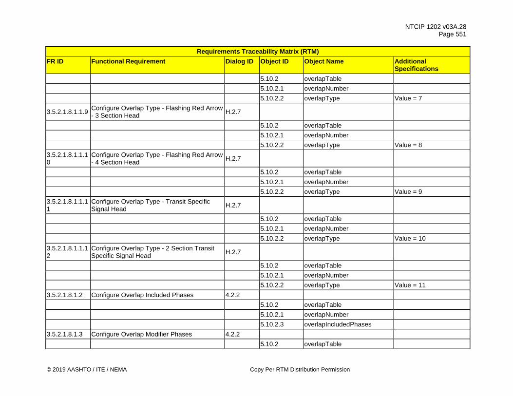
NTCIP 1202 v03A.28 Page 551
© 2019 AASHTO / ITE / NEMA Copy Per RTM Distribution Permission
Requirements Traceability Matrix (RTM) FR ID Functional Requirement Dialog ID Object ID Object Name Additional
Specifications 5.10.2 overlapTable 5.10.2.1 overlapNumber 5.10.2.2 overlapType Value = 7
3.5.2.1.8.1.1.9 Configure Overlap Type - Flashing Red Arrow - 3 Section Head H.2.7
5.10.2 overlapTable 5.10.2.1 overlapNumber 5.10.2.2 overlapType Value = 8 3.5.2.1.8.1.1.10
Configure Overlap Type - Flashing Red Arrow - 4 Section Head H.2.7
5.10.2 overlapTable 5.10.2.1 overlapNumber 5.10.2.2 overlapType Value = 9 3.5.2.1.8.1.1.11
Configure Overlap Type - Transit Specific Signal Head H.2.7
5.10.2 overlapTable 5.10.2.1 overlapNumber 5.10.2.2 overlapType Value = 10 3.5.2.1.8.1.1.12
Configure Overlap Type - 2 Section Transit Specific Signal Head H.2.7
5.10.2 overlapTable 5.10.2.1 overlapNumber 5.10.2.2 overlapType Value = 11 3.5.2.1.8.1.2 Configure Overlap Included Phases 4.2.2 5.10.2 overlapTable 5.10.2.1 overlapNumber 5.10.2.3 overlapIncludedPhases 3.5.2.1.8.1.3 Configure Overlap Modifier Phases 4.2.2 5.10.2 overlapTable

NTCIP 1202 v03A.28 Page 552
Copy Per RTM Distribution Permission © 2019 AASHTO / ITE / NEMA
Requirements Traceability Matrix (RTM) FR ID Functional Requirement Dialog ID Object ID Object Name Additional
Specifications 5.10.2.1 overlapNumber 5.10.2.4 overlapModifierPhases 3.5.2.1.8.1.4 Configure Pedestrian Modifier Phases 4.2.2 5.10.2 overlapTable 5.10.2.1 overlapNumber 5.10.2.10 overlapConflictingPedPhases 3.5.2.1.8.1.5 Configure Overlap Trailing Green H.2.7 5.10.2 overlapTable 5.10.2.1 overlapNumber 5.10.2.5 overlapTrailGreen 3.5.2.1.8.1.6 Configure Overlap Trailing Yellow H.2.7 5.10.2 overlapTable 5.10.2.1 overlapNumber 5.10.2.6 overlapTrailYellow 3.5.2.1.8.1.7 Configure Overlap Trailing Red Clearance H.2.7 5.10.2 overlapTable 5.10.2.1 overlapNumber 5.10.2.7 overlapTrailRed 3.5.2.1.8.1.8 Configure Overlap Walk H.2.7 5.10.2 overlapTable 5.10.2.1 overlapNumber 5.10.2.8 overlapWalk 3.5.2.1.8.1.9 Configure Overlap Pedestrian Clearance H.2.7 5.10.2 overlapTable 5.10.2.1 overlapNumber 5.10.2.9 overlapPedClearance 3.5.2.1.8.2 Retrieve Overlaps Requirements 3.5.2.1.8.2.1 Determine Maximum Number of Overlaps G.1
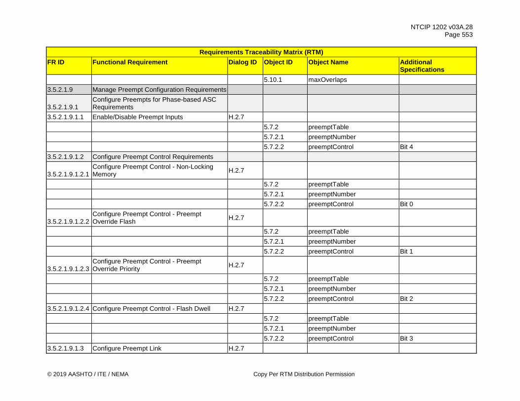
NTCIP 1202 v03A.28 Page 553
© 2019 AASHTO / ITE / NEMA Copy Per RTM Distribution Permission
Requirements Traceability Matrix (RTM) FR ID Functional Requirement Dialog ID Object ID Object Name Additional
Specifications 5.10.1 maxOverlaps 3.5.2.1.9 Manage Preempt Configuration Requirements
3.5.2.1.9.1 Configure Preempts for Phase-based ASC Requirements
3.5.2.1.9.1.1 Enable/Disable Preempt Inputs H.2.7 5.7.2 preemptTable 5.7.2.1 preemptNumber 5.7.2.2 preemptControl Bit 4 3.5.2.1.9.1.2 Configure Preempt Control Requirements
3.5.2.1.9.1.2.1 Configure Preempt Control - Non-Locking Memory H.2.7
5.7.2 preemptTable 5.7.2.1 preemptNumber 5.7.2.2 preemptControl Bit 0
3.5.2.1.9.1.2.2 Configure Preempt Control - Preempt Override Flash H.2.7
5.7.2 preemptTable 5.7.2.1 preemptNumber 5.7.2.2 preemptControl Bit 1
3.5.2.1.9.1.2.3 Configure Preempt Control - Preempt Override Priority H.2.7
5.7.2 preemptTable 5.7.2.1 preemptNumber 5.7.2.2 preemptControl Bit 2 3.5.2.1.9.1.2.4 Configure Preempt Control - Flash Dwell H.2.7 5.7.2 preemptTable 5.7.2.1 preemptNumber 5.7.2.2 preemptControl Bit 3 3.5.2.1.9.1.3 Configure Preempt Link H.2.7
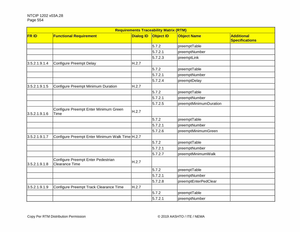
NTCIP 1202 v03A.28 Page 554
Copy Per RTM Distribution Permission © 2019 AASHTO / ITE / NEMA
Requirements Traceability Matrix (RTM) FR ID Functional Requirement Dialog ID Object ID Object Name Additional
Specifications 5.7.2 preemptTable 5.7.2.1 preemptNumber 5.7.2.3 preemptLink 3.5.2.1.9.1.4 Configure Preempt Delay H.2.7 5.7.2 preemptTable 5.7.2.1 preemptNumber 5.7.2.4 preemptDelay 3.5.2.1.9.1.5 Configure Preempt Minimum Duration H.2.7 5.7.2 preemptTable 5.7.2.1 preemptNumber 5.7.2.5 preemptMinimumDuration
3.5.2.1.9.1.6 Configure Preempt Enter Minimum Green Time H.2.7
5.7.2 preemptTable 5.7.2.1 preemptNumber 5.7.2.6 preemptMinimumGreen 3.5.2.1.9.1.7 Configure Preempt Enter Minimum Walk Time H.2.7 5.7.2 preemptTable 5.7.2.1 preemptNumber 5.7.2.7 preemptMinimumWalk
3.5.2.1.9.1.8 Configure Preempt Enter Pedestrian Clearance Time H.2.7
5.7.2 preemptTable 5.7.2.1 preemptNumber 5.7.2.8 preemptEnterPedClear 3.5.2.1.9.1.9 Configure Preempt Track Clearance Time H.2.7 5.7.2 preemptTable 5.7.2.1 preemptNumber

NTCIP 1202 v03A.28 Page 555
© 2019 AASHTO / ITE / NEMA Copy Per RTM Distribution Permission
Requirements Traceability Matrix (RTM) FR ID Functional Requirement Dialog ID Object ID Object Name Additional
Specifications 5.7.2.9 preemptTrackGreen 3.5.2.1.9.1.10 Configure Preempt Minimum Dwell Time H.2.7 5.7.2 preemptTable 5.7.2.1 preemptNumber 5.7.2.10 preemptDwellGreen 3.5.2.1.9.1.11 Configure Preempt Maximum Presence Time H.2.7 5.7.2 preemptTable 5.7.2.1 preemptNumber 5.7.2.11 preemptMaximumPresence 3.5.2.1.9.1.12 Configure Preempt Track Clearance Phases H.2.7 5.7.2 preemptTable 5.7.2.1 preemptNumber 5.7.2.12 preemptTrackPhase 3.5.2.1.9.1.13 Configure Preempt Dwell Phases H.2.7 5.7.2 preemptTable 5.7.2.1 preemptNumber 5.7.2.13 preemptDwellPhase
3.5.2.1.9.1.14 Configure Preempt Dwell Pedestrian Movements H.2.7
5.7.2 preemptTable 5.7.2.1 preemptNumber 5.7.2.14 preemptDwellPed 3.5.2.1.9.1.15 Configure Preempt Exit Phases H.2.7 5.7.2 preemptTable 5.7.2.1 preemptNumber 5.7.2.15 preemptExitPhase
3.5.2.1.9.1.16 Configure Preempt Exit Phase Strategy Requirements

NTCIP 1202 v03A.28 Page 556
Copy Per RTM Distribution Permission © 2019 AASHTO / ITE / NEMA
Requirements Traceability Matrix (RTM) FR ID Functional Requirement Dialog ID Object ID Object Name Additional
Specifications 3.5.2.1.9.1.16.1
Configure Preempt Exit Phase Strategy - Exit to Normal Operation H.2.7
5.7.2 preemptTable 5.7.2.1 preemptNumber 5.7.2.27 preemptExitType exitPhases (1) 3.5.2.1.9.1.16.2
Configure Preempt Exit Phase Strategy - Exit to Coordination H.2.7
5.7.2 preemptTable 5.7.2.1 preemptNumber 5.7.2.27 preemptExitType exitCoord (4) 3.5.2.1.9.1.16.3
Configure Preempt Exit Phase Strategy - Exit to Queue Delay Recovery H.2.7
5.7.2 preemptTable 5.7.2.1 preemptNumber 5.7.2.27 preemptExitType queueDelayRecovery (2) 3.5.2.1.9.1.16.4
Configure Preempt Exit Phase Strategy - Exit to Short Service Phase H.2.7
5.7.2 preemptTable 5.7.2.1 preemptNumber 5.7.2.27 preemptExitType shortService (3) 3.5.2.1.9.1.17 Configure Preempt Track Overlap H.2.7 5.7.2 preemptTable 5.7.2.1 preemptNumber 5.7.2.17 preemptTrackOverlap 3.5.2.1.9.1.18 Configure Preempt Dwell Overlap H.2.7 5.7.2 preemptTable 5.7.2.1 preemptNumber 5.7.2.18 preemptDwellOverlap 3.5.2.1.9.1.19 Configure Preempt Cycling Phases H.2.7

NTCIP 1202 v03A.28 Page 557
© 2019 AASHTO / ITE / NEMA Copy Per RTM Distribution Permission
Requirements Traceability Matrix (RTM) FR ID Functional Requirement Dialog ID Object ID Object Name Additional
Specifications 5.7.2 preemptTable 5.7.2.1 preemptNumber 5.7.2.19 preemptCyclingPhase
3.5.2.1.9.1.20 Configure Preempt Cycling Pedestrian Movements H.2.7
5.7.2 preemptTable 5.7.2.1 preemptNumber 5.7.2.20 preemptCyclingPed 3.5.2.1.9.1.21 Configure Preempt Cycling Overlaps H.2.7 5.7.2 preemptTable 5.7.2.1 preemptNumber 5.7.2.21 preemptCyclingOverlap
3.5.2.1.9.1.22 Configure Preempt Enter Yellow Change Time H.2.7
5.7.2 preemptTable 5.7.2.1 preemptNumber 5.7.2.22 preemptEnterYellowChange
3.5.2.1.9.1.23 Configure Preempt Enter Red Clearance Time H.2.7
5.7.2 preemptTable 5.7.2.1 preemptNumber 5.7.2.23 preemptEnterRedClear
3.5.2.1.9.1.24 Configure Preempt Track Yellow Change Time H.2.7
5.7.2 preemptTable 5.7.2.1 preemptNumber 5.7.2.24 preemptTrackYellowChange
3.5.2.1.9.1.25 Configure Preempt Track Red Clearance Time H.2.7

NTCIP 1202 v03A.28 Page 558
Copy Per RTM Distribution Permission © 2019 AASHTO / ITE / NEMA
Requirements Traceability Matrix (RTM) FR ID Functional Requirement Dialog ID Object ID Object Name Additional
Specifications 5.7.2 preemptTable 5.7.2.1 preemptNumber 5.7.2.25 preemptTrackRedClear 3.5.2.1.9.1.26 Configure Preempt Exit Priority Levels H.2.7 5.3.2.1 vehicleDetectorNumber 5.7.7 preemptQueueDelayTable 5.7.7.1 preemptDetectorWeight
3.5.2.1.9.1.27 Configure Preempt Max Presence Exceeded Requirements
3.5.2.1.9.1.27.1
Configure Preempt Max Presence Exceeded - Normal H.2.7
5.7.2 preemptTable 5.7.2.1 preemptNumber 5.7.2.11 preemptMaximumPresence 3.5.2.1.9.1.27.2
Configure Preempt Max Presence Exceeded - All Flash Red H.2.7
5.7.2 preemptTable 5.7.2.1 preemptNumber 5.7.2.2 preemptControl Bit 5 3.5.2.1.9.1.28 Configure Preempt Cycling Phases Sequence H.2.7 5.7.2 preemptTable 5.7.2.1 preemptNumber 5.7.2.13 preemptDwellPhase
3.5.2.1.9.1.29 Configure Preempt Enter Minimum Bicycle Time H.2.7
5.7.2 preemptTable 5.7.2.1 preemptNumber 5.7.2.6 preemptMinimumGreen

NTCIP 1202 v03A.28 Page 559
© 2019 AASHTO / ITE / NEMA Copy Per RTM Distribution Permission
Requirements Traceability Matrix (RTM) FR ID Functional Requirement Dialog ID Object ID Object Name Additional
Specifications
3.5.2.1.9.1.30 Configure Preempt Enter Bicycle Clearance Time H.2.7
5.7.2 preemptTable 5.7.2.1 preemptNumber 5.7.2.22 preemptEnterYellowChange 3.5.2.1.9.1.31 Configure Preempt Cycling Bicycle Phases H.2.7 5.7.2 preemptTable 5.7.2.1 preemptNumber 5.7.2.26 preemptSequenceNumber
3.5.2.1.9.1.32 Configure Preempt Enter Minimum Transit Time H.2.7
5.7.2 preemptTable 5.7.2.1 preemptNumber 5.7.2.6 preemptMinimumGreen
3.5.2.1.9.1.33 Configure Preempt Enter Transit Clearance Time H.2.7
5.7.2 preemptTable 5.7.2.1 preemptNumber 5.7.2.22 preemptEnterYellowChange 3.5.2.1.9.1.34 Configure Preempt Cycling Transit Phases H.2.7 5.7.2 preemptTable 5.7.2.1 preemptNumber 5.7.2.13 preemptDwellPhase
3.5.2.1.9.2 Retrieve Preempt Configuration for Phase-based ASC Requirements
3.5.2.1.9.2.1 Determine Maximum Number of Preempts G.1 5.7.1 maxPreempts
3.5.2.1.10 Manage Timing Pattern Scheduler Requirements
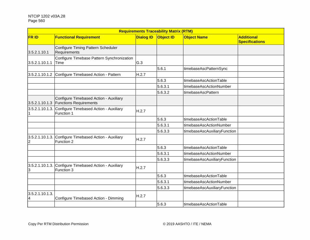
NTCIP 1202 v03A.28 Page 560
Copy Per RTM Distribution Permission © 2019 AASHTO / ITE / NEMA
Requirements Traceability Matrix (RTM) FR ID Functional Requirement Dialog ID Object ID Object Name Additional
Specifications
3.5.2.1.10.1 Configure Timing Pattern Scheduler Requirements
3.5.2.1.10.1.1 Configure Timebase Pattern Synchronization Time G.3
5.6.1 timebaseAscPatternSync 3.5.2.1.10.1.2 Configure Timebased Action - Pattern H.2.7 5.6.3 timebaseAscActionTable 5.6.3.1 timebaseAscActionNumber 5.6.3.2 timebaseAscPattern
3.5.2.1.10.1.3 Configure Timebased Action - Auxiliary Functions Requirements
3.5.2.1.10.1.3.1
Configure Timebased Action - Auxiliary Function 1 H.2.7
5.6.3 timebaseAscActionTable 5.6.3.1 timebaseAscActionNumber 5.6.3.3 timebaseAscAuxiliaryFunction 3.5.2.1.10.1.3.2
Configure Timebased Action - Auxiliary Function 2 H.2.7
5.6.3 timebaseAscActionTable 5.6.3.1 timebaseAscActionNumber 5.6.3.3 timebaseAscAuxiliaryFunction 3.5.2.1.10.1.3.3
Configure Timebased Action - Auxiliary Function 3 H.2.7
5.6.3 timebaseAscActionTable 5.6.3.1 timebaseAscActionNumber 5.6.3.3 timebaseAscAuxiliaryFunction 3.5.2.1.10.1.3.4 Configure Timebased Action - Dimming H.2.7
5.6.3 timebaseAscActionTable
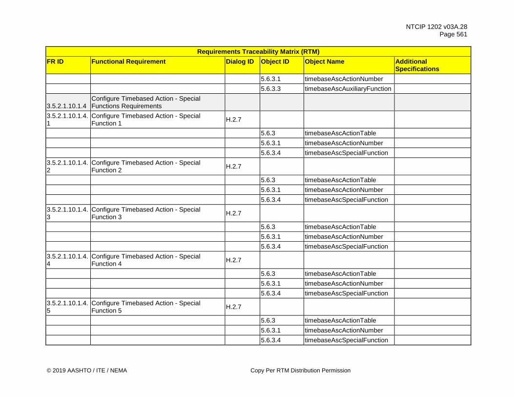
NTCIP 1202 v03A.28 Page 561
© 2019 AASHTO / ITE / NEMA Copy Per RTM Distribution Permission
Requirements Traceability Matrix (RTM) FR ID Functional Requirement Dialog ID Object ID Object Name Additional
Specifications 5.6.3.1 timebaseAscActionNumber 5.6.3.3 timebaseAscAuxiliaryFunction
3.5.2.1.10.1.4 Configure Timebased Action - Special Functions Requirements
3.5.2.1.10.1.4.1
Configure Timebased Action - Special Function 1 H.2.7
5.6.3 timebaseAscActionTable 5.6.3.1 timebaseAscActionNumber 5.6.3.4 timebaseAscSpecialFunction 3.5.2.1.10.1.4.2
Configure Timebased Action - Special Function 2 H.2.7
5.6.3 timebaseAscActionTable 5.6.3.1 timebaseAscActionNumber 5.6.3.4 timebaseAscSpecialFunction 3.5.2.1.10.1.4.3
Configure Timebased Action - Special Function 3 H.2.7
5.6.3 timebaseAscActionTable 5.6.3.1 timebaseAscActionNumber 5.6.3.4 timebaseAscSpecialFunction 3.5.2.1.10.1.4.4
Configure Timebased Action - Special Function 4 H.2.7
5.6.3 timebaseAscActionTable 5.6.3.1 timebaseAscActionNumber 5.6.3.4 timebaseAscSpecialFunction 3.5.2.1.10.1.4.5
Configure Timebased Action - Special Function 5 H.2.7
5.6.3 timebaseAscActionTable 5.6.3.1 timebaseAscActionNumber 5.6.3.4 timebaseAscSpecialFunction

NTCIP 1202 v03A.28 Page 562
Copy Per RTM Distribution Permission © 2019 AASHTO / ITE / NEMA
Requirements Traceability Matrix (RTM) FR ID Functional Requirement Dialog ID Object ID Object Name Additional
Specifications 3.5.2.1.10.1.4.6
Configure Timebased Action - Special Function 6 H.2.7
5.6.3 timebaseAscActionTable 5.6.3.1 timebaseAscActionNumber 5.6.3.4 timebaseAscSpecialFunction 3.5.2.1.10.1.4.7
Configure Timebased Action - Special Function 7 H.2.7
5.6.3 timebaseAscActionTable 5.6.3.1 timebaseAscActionNumber 5.6.3.4 timebaseAscSpecialFunction 3.5.2.1.10.1.4.8
Configure Timebased Action - Special Function 8 H.2.7
5.6.3 timebaseAscActionTable 5.6.3.1 timebaseAscActionNumber 5.6.3.4 timebaseAscSpecialFunction
3.5.2.1.10.2 Retrieve Timing Pattern Scheduler Requirements
3.5.2.1.10.2.1 Determine Maximum Number of Timebased Actions G.1
5.6.2 maxTimebaseAscActions 3.5.2.1.10.2.2 Determine Action In Effect G.1 5.6.4 timebaseAscActionStatus 3.5.2.1.11 Manage I/O Mapping Requirements 3.5.2.1.11.1 Configure I/O Mapping Requirements 3.5.2.1.11.1.1 Set Active I/O Map 4.2.5 5.14.1.2 ascIOactiveMap 5.14.1.3 ascIOactivateRequirement 3.5.2.1.11.1.2 Configure I/O Map Requirements

NTCIP 1202 v03A.28 Page 563
© 2019 AASHTO / ITE / NEMA Copy Per RTM Distribution Permission
Requirements Traceability Matrix (RTM) FR ID Functional Requirement Dialog ID Object ID Object Name Additional
Specifications 3.5.2.1.11.1.2.1
Configure I/O Map Description 4.2.4
5.14.4.1 ascIOmapNumber 5.14.8 ascIOmapDescriptionTable 5.14.8.1 ascIOmapDescription 3.5.2.1.11.1.2.2
Configure I/O Map Input Requirements
3.5.2.1.11.1.2.2.1
Configure I/O Map Input Device 4.2.4
5.14.4 ascIOinputMapTable 5.14.4.1 ascIOmapNumber 5.14.4.2 ascIOinputMapIOindex 5.14.4.3 ascIOinputMapDeviceType 5.14.4.4 ascIOinputMapDevicePNN 5.14.4.5 ascIOinputMapDevicePtype 5.14.4.6 ascIOinputMapDeviceAddr 3.5.2.1.11.1.2.2.2
Configure I/O Map Input Device Pin 4.2.4
5.14.4 ascIOinputMapTable 5.14.4.1 ascIOmapNumber 5.14.4.2 ascIOinputMapIOindex 5.14.4.3 ascIOinputMapDeviceType 5.14.4.4 ascIOinputMapDevicePNN 5.14.4.5 ascIOinputMapDevicePtype 5.14.4.7 ascIOinputMapDevicePin 3.5.2.1.11.1.2.2.3
Configure I/O Map Input Function 4.2.4
5.14.4 ascIOinputMapTable 5.14.4.1 ascIOmapNumber

NTCIP 1202 v03A.28 Page 564
Copy Per RTM Distribution Permission © 2019 AASHTO / ITE / NEMA
Requirements Traceability Matrix (RTM) FR ID Functional Requirement Dialog ID Object ID Object Name Additional
Specifications 5.14.4.2 ascIOinputMapIOindex 5.14.4.8 ascIOinputMapFuncType 5.14.4.9 ascIOinputMapFuncPtype 5.14.4.10 ascIOinputMapFunction 5.14.4.11 ascIOinputMapFuncIndex 3.5.2.1.11.1.2.3
Configure I/O Map Output Requirements
3.5.2.1.11.1.2.3.1
Configure I/O Map Output Device 4.2.4
5.14.6 ascIOoutputMapTable 5.14.4.1 ascIOmapNumber 5.14.6.1 ascIOoutputMapIOindex 5.14.6.2 ascIOoutputMapDeviceType 5.14.6.3 ascIOoutputMapDevicePNN 5.14.6.4 ascIOoutputMapDevicePtype 5.14.6.5 ascIOoutputMapDeviceAddr 3.5.2.1.11.1.2.3.2
Configure I/O Map Output Device Pin 4.2.4
5.14.6 ascIOoutputMapTable 5.14.4.1 ascIOmapNumber 5.14.6.1 ascIOoutputMapIOindex 5.14.6.2 ascIOoutputMapDeviceType 5.14.6.3 ascIOoutputMapDevicePNN 5.14.6.4 ascIOoutputMapDevicePtype 5.14.6.6 ascIOoutputMapDevicePin 3.5.2.1.11.1.2.3.3
Configure I/O Map Output Function 4.2.4
5.14.6 ascIOoutputMapTable 5.14.4.1 ascIOmapNumber
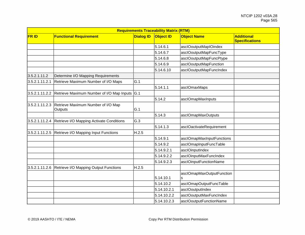
NTCIP 1202 v03A.28 Page 565
© 2019 AASHTO / ITE / NEMA Copy Per RTM Distribution Permission
Requirements Traceability Matrix (RTM) FR ID Functional Requirement Dialog ID Object ID Object Name Additional
Specifications 5.14.6.1 ascIOoutputMapIOindex 5.14.6.7 ascIOoutputMapFuncType 5.14.6.8 ascIOoutputMapFuncPtype 5.14.6.9 ascIOoutputMapFunction 5.14.6.10 ascIOoutputMapFuncIndex 3.5.2.1.11.2 Determine I/O Mapping Requirements 3.5.2.1.11.2.1 Retrieve Maximum Number of I/O Maps G.1 5.14.1.1 ascIOmaxMaps 3.5.2.1.11.2.2 Retrieve Maximum Number of I/O Map Inputs G.1 5.14.2 ascIOmapMaxInputs 3.5.2.1.11.2.3 Retrieve Maximum Number of I/O Map
Outputs G.1
5.14.3 ascIOmapMaxOutputs 3.5.2.1.11.2.4 Retrieve I/O Mapping Activate Conditions G.3 5.14.1.3 ascIOactivateRequirement 3.5.2.1.11.2.5 Retrieve I/O Mapping Input Functions H.2.5 5.14.9.1 ascIOmapMaxInputFunctions 5.14.9.2 ascIOmapInputFuncTable 5.14.9.2.1 ascIOinputIndex 5.14.9.2.2 ascIOinputMaxFuncIndex 5.14.9.2.3 ascIOinputFunctionName 3.5.2.1.11.2.6 Retrieve I/O Mapping Output Functions H.2.5
5.14.10.1 ascIOmapMaxOutputFunctions
5.14.10.2 ascIOmapOutputFuncTable 5.14.10.2.1 ascIOoutputIndex 5.14.10.2.2 ascIOoutputMaxFuncIndex 5.14.10.2.3 ascIOoutputFunctionName

NTCIP 1202 v03A.28 Page 566
Copy Per RTM Distribution Permission © 2019 AASHTO / ITE / NEMA
Requirements Traceability Matrix (RTM) FR ID Functional Requirement Dialog ID Object ID Object Name Additional
Specifications 3.5.2.1.11.2.7 Retrieve I/O Map Input Device Pin Status H.2.5 5.14.1.1 ascIOmaxMaps 5.14.2 ascIOmapMaxInputs 5.14.4.1 ascIOmapNumber 5.14.4.2 ascIOinputMapIOindex 5.14.5 ascIOinputMapStatusTable 5.14.5.1 ascIOinputMapDevPinDescr 5.14.5.2 ascIOinputMapDevPinStatus 3.5.2.1.11.2.8 Retrieve I/O Map Output Device Pin Status H.2.5 5.14.1.1 ascIOmaxMaps 5.14.3 ascIOmapMaxOutputs 5.14.4.1 ascIOmapNumber 5.14.6.1 ascIOoutputMapIOindex 5.14.7 ascIOoutputMapStatusTable 5.14.7.1 ascIOoutputMapDevPinDescr 5.14.7.2 ascIOoutputMapDevPinStatus 3.5.2.1.11.2.9 Enumerate I/O Mapping Device Pin
Requirements
3.5.2.1.11.2.9.1
Enumerate I/O Map - FIO Inputs
5.14.11.1 - AscIOmapFIOinputs
3.5.2.1.11.2.9.2
Enumerate I/O Map - FIO Outputs
5.14.11.2 - AscIOmapFIOoutputs
3.5.2.1.11.2.9.3
Enumerate I/O Map - TS1 Inputs
5.14.12.1 - AscIOmapTS1inputs
3.5.2.1.11.2.9.4
Enumerate I/O Map - TS1 Outputs
5.14.12.2 - AscIOmapTS1outputs
3.5.2.1.11.2.9.5
Enumerate I/O Map - TS2 BIU Inputs
5.14.13.1 - AscIOmapBIUinputs
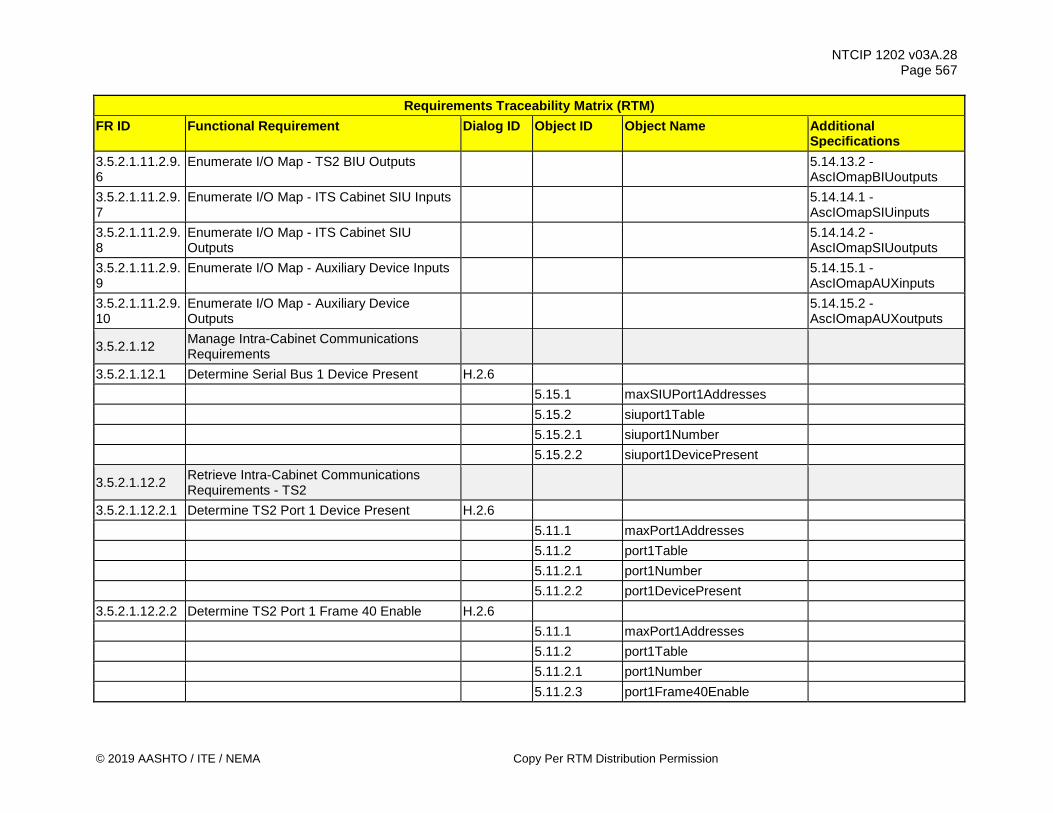
NTCIP 1202 v03A.28 Page 567
© 2019 AASHTO / ITE / NEMA Copy Per RTM Distribution Permission
Requirements Traceability Matrix (RTM) FR ID Functional Requirement Dialog ID Object ID Object Name Additional
Specifications 3.5.2.1.11.2.9.6
Enumerate I/O Map - TS2 BIU Outputs
5.14.13.2 - AscIOmapBIUoutputs
3.5.2.1.11.2.9.7
Enumerate I/O Map - ITS Cabinet SIU Inputs
5.14.14.1 - AscIOmapSIUinputs
3.5.2.1.11.2.9.8
Enumerate I/O Map - ITS Cabinet SIU Outputs
5.14.14.2 - AscIOmapSIUoutputs
3.5.2.1.11.2.9.9
Enumerate I/O Map - Auxiliary Device Inputs
5.14.15.1 - AscIOmapAUXinputs
3.5.2.1.11.2.9.10
Enumerate I/O Map - Auxiliary Device Outputs
5.14.15.2 - AscIOmapAUXoutputs
3.5.2.1.12 Manage Intra-Cabinet Communications Requirements
3.5.2.1.12.1 Determine Serial Bus 1 Device Present H.2.6 5.15.1 maxSIUPort1Addresses 5.15.2 siuport1Table 5.15.2.1 siuport1Number 5.15.2.2 siuport1DevicePresent
3.5.2.1.12.2 Retrieve Intra-Cabinet Communications Requirements - TS2
3.5.2.1.12.2.1 Determine TS2 Port 1 Device Present H.2.6 5.11.1 maxPort1Addresses 5.11.2 port1Table 5.11.2.1 port1Number 5.11.2.2 port1DevicePresent 3.5.2.1.12.2.2 Determine TS2 Port 1 Frame 40 Enable H.2.6 5.11.1 maxPort1Addresses 5.11.2 port1Table 5.11.2.1 port1Number 5.11.2.3 port1Frame40Enable

NTCIP 1202 v03A.28 Page 568
Copy Per RTM Distribution Permission © 2019 AASHTO / ITE / NEMA
Requirements Traceability Matrix (RTM) FR ID Functional Requirement Dialog ID Object ID Object Name Additional
Specifications 3.5.2.1.13 Manage ADA Support Requirements 3.5.2.1.13.1 Configure ADA Support Requirements
3.5.2.1.13.1.1 Configure APS Push Button Minimum Press Time H.2.7
5.3.7 pedestrianDetectorTable 5.3.7.1 pedestrianDetectorNumber 5.3.7.8 pedestrianButtonPushTime
3.5.2.1.13.1.2 Configure APS Push Button to Phase Association H.2.7
5.3.7 pedestrianDetectorTable 5.3.7.1 pedestrianDetectorNumber 5.3.7.2 pedestrianDetectorCallPhase 3.5.2.1.13.1.3 Configure APS Extra Crossing Time 4.2.2 5.2.2 phaseTable 5.2.2.1 phaseNumber 5.2.2.28 phasePedAlternateClearance 5.2.2.29 phasePedAlternateWalk
3.5.2.1.13.2 Determine Maximum Number of Pedestrian Buttons G.1
5.3.6 maxPedestrianDetectors 3.5.2.1.14 Manage Block Object Requirements 3.5.2.1.14.1 Configure Block Object Requirements
3.5.2.1.14.1.1 Configure Block Object Get Control Requirements
3.5.2.1.14.1.1.1
Configure Block Object Get Control - Phase Data 4.2.3
1201v03 - 2.3.1
dbCreateTransaction

NTCIP 1202 v03A.28 Page 569
© 2019 AASHTO / ITE / NEMA Copy Per RTM Distribution Permission
Requirements Traceability Matrix (RTM) FR ID Functional Requirement Dialog ID Object ID Object Name Additional
Specifications
1201v03 - 2.3.6
dbVerifyStatus
1201v03 - 2.3.7
dbVerifyError
5.12.2 ascBlockData 6.2 - AscPhaseBlock 3.5.2.1.14.1.1.2
Configure Block Object Get Control - Vehicle Detector Data
4.2.3
1201v03 - 2.3.1
dbCreateTransaction
1201v03 - 2.3.6
dbVerifyStatus
1201v03 - 2.3.7
dbVerifyError
5.12.2 ascBlockData 6.3 - AscVehDetectorBlock
3.5.2.1.14.1.1.3
Configure Block Object Get Control - Pedestrian Detector Data
4.2.3
1201v03 - 2.3.1
dbCreateTransaction
1201v03 - 2.3.6
dbVerifyStatus
1201v03 - 2.3.7
dbVerifyError
5.12.2 ascBlockData 6.4 - AscPedDetectorBlock
3.5.2.1.14.1.1.4
Configure Block Object Get Control - Pattern Data
4.2.3
1201v03 - 2.3.1
dbCreateTransaction
1201v03 - 2.3.6
dbVerifyStatus

NTCIP 1202 v03A.28 Page 570
Copy Per RTM Distribution Permission © 2019 AASHTO / ITE / NEMA
Requirements Traceability Matrix (RTM) FR ID Functional Requirement Dialog ID Object ID Object Name Additional
Specifications
1201v03 - 2.3.7
dbVerifyError
5.12.2 ascBlockData 6.5 - AscPatternBlock 3.5.2.1.14.1.1.5
Configure Block Object Get Control - Split Data
4.2.3
1201v03 - 2.3.1
dbCreateTransaction
1201v03 - 2.3.6
dbVerifyStatus
1201v03 - 2.3.7
dbVerifyError
5.12.2 ascBlockData 6.6 - AscSplitBlock 3.5.2.1.14.1.1.6
Configure Block Object Get Control - Time Base Data
4.2.3
1201v03 - 2.3.1
dbCreateTransaction
1201v03 - 2.3.6
dbVerifyStatus
1201v03 - 2.3.7
dbVerifyError
5.12.2 ascBlockData 6.7 - AscTimebaseBlock 3.5.2.1.14.1.1.7
Configure Block Object Get Control - Preempt Data
4.2.3
1201v03 - 2.3.1
dbCreateTransaction
1201v03 - 2.3.6
dbVerifyStatus
1201v03 - 2.3.7
dbVerifyError
5.12.2 ascBlockData 6.8 - AscPreemptBlock
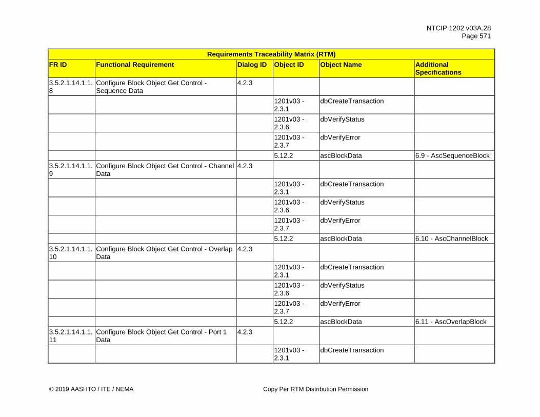
NTCIP 1202 v03A.28 Page 571
© 2019 AASHTO / ITE / NEMA Copy Per RTM Distribution Permission
Requirements Traceability Matrix (RTM) FR ID Functional Requirement Dialog ID Object ID Object Name Additional
Specifications 3.5.2.1.14.1.1.8
Configure Block Object Get Control - Sequence Data
4.2.3
1201v03 - 2.3.1
dbCreateTransaction
1201v03 - 2.3.6
dbVerifyStatus
1201v03 - 2.3.7
dbVerifyError
5.12.2 ascBlockData 6.9 - AscSequenceBlock 3.5.2.1.14.1.1.9
Configure Block Object Get Control - Channel Data
4.2.3
1201v03 - 2.3.1
dbCreateTransaction
1201v03 - 2.3.6
dbVerifyStatus
1201v03 - 2.3.7
dbVerifyError
5.12.2 ascBlockData 6.10 - AscChannelBlock 3.5.2.1.14.1.1.10
Configure Block Object Get Control - Overlap Data
4.2.3
1201v03 - 2.3.1
dbCreateTransaction
1201v03 - 2.3.6
dbVerifyStatus
1201v03 - 2.3.7
dbVerifyError
5.12.2 ascBlockData 6.11 - AscOverlapBlock 3.5.2.1.14.1.1.11
Configure Block Object Get Control - Port 1 Data
4.2.3
1201v03 - 2.3.1
dbCreateTransaction

NTCIP 1202 v03A.28 Page 572
Copy Per RTM Distribution Permission © 2019 AASHTO / ITE / NEMA
Requirements Traceability Matrix (RTM) FR ID Functional Requirement Dialog ID Object ID Object Name Additional
Specifications
1201v03 - 2.3.6
dbVerifyStatus
1201v03 - 2.3.7
dbVerifyError
5.12.2 ascBlockData 6.12 - AscPort1Block 3.5.2.1.14.1.1.12
Configure Block Object Get Control - Schedule Data
4.2.3
1201v03 - 2.3.1
dbCreateTransaction
1201v03 - 2.3.6
dbVerifyStatus
1201v03 - 2.3.7
dbVerifyError
5.12.2 ascBlockData 6.13 - AscScheduleBlock 3.5.2.1.14.1.1.13
Configure Block Object Get Control - Day Plan Data
4.2.3
1201v03 - 2.3.1
dbCreateTransaction
1201v03 - 2.3.6
dbVerifyStatus
1201v03 - 2.3.7
dbVerifyError
5.12.2 ascBlockData 6.14 - AscDayPlanBlock
3.5.2.1.14.1.1.14
Configure Block Object Get Control - Event Configuration Data
4.2.3
1201v03 - 2.3.1
dbCreateTransaction
1201v03 - 2.3.6
dbVerifyStatus
1201v03 - 2.3.7
dbVerifyError
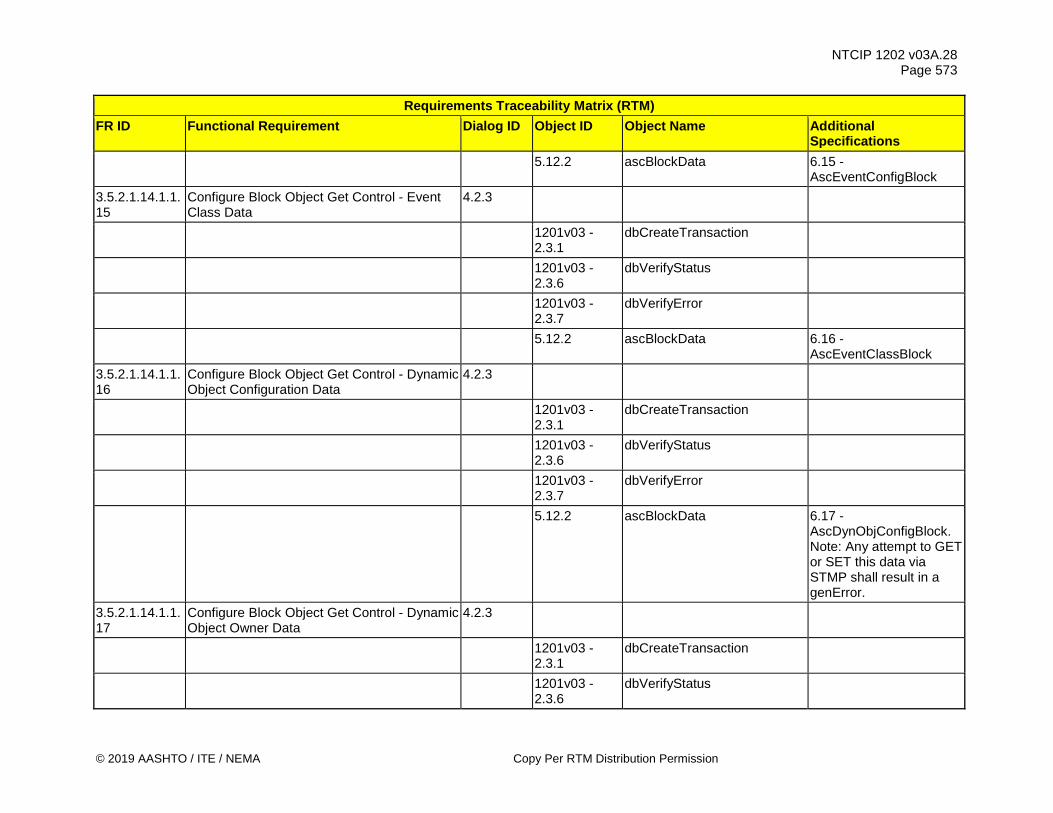
NTCIP 1202 v03A.28 Page 573
© 2019 AASHTO / ITE / NEMA Copy Per RTM Distribution Permission
Requirements Traceability Matrix (RTM) FR ID Functional Requirement Dialog ID Object ID Object Name Additional
Specifications
5.12.2 ascBlockData 6.15 - AscEventConfigBlock
3.5.2.1.14.1.1.15
Configure Block Object Get Control - Event Class Data
4.2.3
1201v03 - 2.3.1
dbCreateTransaction
1201v03 - 2.3.6
dbVerifyStatus
1201v03 - 2.3.7
dbVerifyError
5.12.2 ascBlockData 6.16 - AscEventClassBlock
3.5.2.1.14.1.1.16
Configure Block Object Get Control - Dynamic Object Configuration Data
4.2.3
1201v03 - 2.3.1
dbCreateTransaction
1201v03 - 2.3.6
dbVerifyStatus
1201v03 - 2.3.7
dbVerifyError
5.12.2 ascBlockData 6.17 - AscDynObjConfigBlock. Note: Any attempt to GET or SET this data via STMP shall result in a genError.
3.5.2.1.14.1.1.17
Configure Block Object Get Control - Dynamic Object Owner Data
4.2.3
1201v03 - 2.3.1
dbCreateTransaction
1201v03 - 2.3.6
dbVerifyStatus
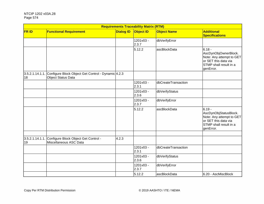
NTCIP 1202 v03A.28 Page 574
Copy Per RTM Distribution Permission © 2019 AASHTO / ITE / NEMA
Requirements Traceability Matrix (RTM) FR ID Functional Requirement Dialog ID Object ID Object Name Additional
Specifications
1201v03 - 2.3.7
dbVerifyError
5.12.2 ascBlockData 6.18 - AscDynObjOwnerBlock. Note: Any attempt to GET or SET this data via STMP shall result in a genError.
3.5.2.1.14.1.1.18
Configure Block Object Get Control - Dynamic Object Status Data
4.2.3
1201v03 - 2.3.1
dbCreateTransaction
1201v03 - 2.3.6
dbVerifyStatus
1201v03 - 2.3.7
dbVerifyError
5.12.2 ascBlockData 6.19 - AscDynObjStatusBlock. Note: Any attempt to GET or SET this data via STMP shall result in a genError.
3.5.2.1.14.1.1.19
Configure Block Object Get Control - Miscellaneous ASC Data
4.2.3
1201v03 - 2.3.1
dbCreateTransaction
1201v03 - 2.3.6
dbVerifyStatus
1201v03 - 2.3.7
dbVerifyError
5.12.2 ascBlockData 6.20 - AscMiscBlock

NTCIP 1202 v03A.28 Page 575
© 2019 AASHTO / ITE / NEMA Copy Per RTM Distribution Permission
Requirements Traceability Matrix (RTM) FR ID Functional Requirement Dialog ID Object ID Object Name Additional
Specifications 3.5.2.1.14.1.1.20
Configure Block Object Get Control - Version 3 Additional Phase Data
4.2.3
1201v03 - 2.3.1
dbCreateTransaction
1201v03 - 2.3.6
dbVerifyStatus
1201v03 - 2.3.7
dbVerifyError
5.12.2 ascBlockData 6.21 - AscPhase2Block 3.5.2.1.14.1.1.21
Configure Block Object Get Control - Version 3 Additional Vehicle Detector Data
4.2.3
1201v03 - 2.3.1
dbCreateTransaction
1201v03 - 2.3.6
dbVerifyStatus
1201v03 - 2.3.7
dbVerifyError
5.12.2 ascBlockData 6.22 - AscVehDetector2Block
3.5.2.1.14.1.1.22
Configure Block Object Get Control - Version 3 Vehicle Detector Volume Occupancy Report Data
4.2.3
1201v03 - 2.3.1
dbCreateTransaction
1201v03 - 2.3.6
dbVerifyStatus
1201v03 - 2.3.7
dbVerifyError
5.12.2 ascBlockData 6.23 -
AscVehDetVolOccV3Block

NTCIP 1202 v03A.28 Page 576
Copy Per RTM Distribution Permission © 2019 AASHTO / ITE / NEMA
Requirements Traceability Matrix (RTM) FR ID Functional Requirement Dialog ID Object ID Object Name Additional
Specifications 3.5.2.1.14.1.1.23
Configure Block Object Get Control - Version 3 Additional Pedestrian Detector Data
4.2.3
1201v03 - 2.3.1
dbCreateTransaction
1201v03 - 2.3.6
dbVerifyStatus
1201v03 - 2.3.7
dbVerifyError
5.12.2 ascBlockData 6.24 - AscPedDetector2Block
3.5.2.1.14.1.1.24
Configure Block Object Get Control - Version 3 Pedestrian Detector Report Data
4.2.3
1201v03 - 2.3.1
dbCreateTransaction
1201v03 - 2.3.6
dbVerifyStatus
1201v03 - 2.3.7
dbVerifyError
5.12.2 ascBlockData 6.25 -
AscPedDetectorReportBlock
3.5.2.1.14.1.1.25
Configure Block Object Get Control - Version 3 Pedestrian Push Button Configuration Data
4.2.3
1201v03 - 2.3.1
dbCreateTransaction
1201v03 - 2.3.6
dbVerifyStatus
1201v03 - 2.3.7
dbVerifyError
5.12.2 ascBlockData 6.26 -
AscPedButtonConfigBlock
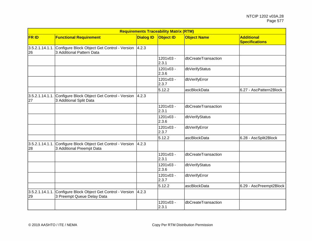
NTCIP 1202 v03A.28 Page 577
© 2019 AASHTO / ITE / NEMA Copy Per RTM Distribution Permission
Requirements Traceability Matrix (RTM) FR ID Functional Requirement Dialog ID Object ID Object Name Additional
Specifications 3.5.2.1.14.1.1.26
Configure Block Object Get Control - Version 3 Additional Pattern Data
4.2.3
1201v03 - 2.3.1
dbCreateTransaction
1201v03 - 2.3.6
dbVerifyStatus
1201v03 - 2.3.7
dbVerifyError
5.12.2 ascBlockData 6.27 - AscPattern2Block 3.5.2.1.14.1.1.27
Configure Block Object Get Control - Version 3 Additional Split Data
4.2.3
1201v03 - 2.3.1
dbCreateTransaction
1201v03 - 2.3.6
dbVerifyStatus
1201v03 - 2.3.7
dbVerifyError
5.12.2 ascBlockData 6.28 - AscSplit2Block 3.5.2.1.14.1.1.28
Configure Block Object Get Control - Version 3 Additional Preempt Data
4.2.3
1201v03 - 2.3.1
dbCreateTransaction
1201v03 - 2.3.6
dbVerifyStatus
1201v03 - 2.3.7
dbVerifyError
5.12.2 ascBlockData 6.29 - AscPreempt2Block 3.5.2.1.14.1.1.29
Configure Block Object Get Control - Version 3 Preempt Queue Delay Data
4.2.3
1201v03 - 2.3.1
dbCreateTransaction
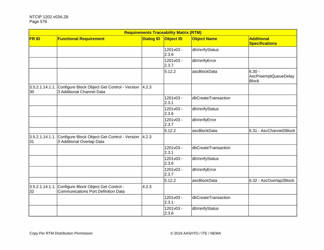
NTCIP 1202 v03A.28 Page 578
Copy Per RTM Distribution Permission © 2019 AASHTO / ITE / NEMA
Requirements Traceability Matrix (RTM) FR ID Functional Requirement Dialog ID Object ID Object Name Additional
Specifications
1201v03 - 2.3.6
dbVerifyStatus
1201v03 - 2.3.7
dbVerifyError
5.12.2 ascBlockData 6.30 -
AscPreemptQueueDelayBlock
3.5.2.1.14.1.1.30
Configure Block Object Get Control - Version 3 Additional Channel Data
4.2.3
1201v03 - 2.3.1
dbCreateTransaction
1201v03 - 2.3.6
dbVerifyStatus
1201v03 - 2.3.7
dbVerifyError
5.12.2 ascBlockData 6.31 - AscChannel2Block 3.5.2.1.14.1.1.31
Configure Block Object Get Control - Version 3 Additional Overlap Data
4.2.3
1201v03 - 2.3.1
dbCreateTransaction
1201v03 - 2.3.6
dbVerifyStatus
1201v03 - 2.3.7
dbVerifyError
5.12.2 ascBlockData 6.32 - AscOverlap2Block 3.5.2.1.14.1.1.32
Configure Block Object Get Control - Communications Port Definition Data
4.2.3
1201v03 - 2.3.1
dbCreateTransaction
1201v03 - 2.3.6
dbVerifyStatus

NTCIP 1202 v03A.28 Page 579
© 2019 AASHTO / ITE / NEMA Copy Per RTM Distribution Permission
Requirements Traceability Matrix (RTM) FR ID Functional Requirement Dialog ID Object ID Object Name Additional
Specifications
1201v03 - 2.3.7
dbVerifyError
5.12.2 ascBlockData 6.33 - AscCommPortDefBlock
3.5.2.1.14.1.1.33
Configure Block Object Get Control – Ethernet Communications Port Definition Data
4.2.3
1201v03 - 2.3.1
dbCreateTransaction
1201v03 - 2.3.6
dbVerifyStatus
1201v03 - 2.3.7
dbVerifyError
5.12.2 ascBlockData 6.34 -
AscEthernetCommPortDefBlock
3.5.2.1.14.1.1.34
Configure Block Object Get Control – SIU Communications Port 1 Definition Data
4.2.3
1201v03 - 2.3.1
dbCreateTransaction
1201v03 - 2.3.6
dbVerifyStatus
1201v03 - 2.3.7
dbVerifyError
5.12.2 ascBlockData 6.35 - AscSiuPort1Block 3.5.2.1.14.1.1.35
Configure Block Object Get Control - Version 3 Additional Miscellaneous ASC Data
4.2.3
1201v03 - 2.3.1
dbCreateTransaction
1201v03 - 2.3.6
dbVerifyStatus

NTCIP 1202 v03A.28 Page 580
Copy Per RTM Distribution Permission © 2019 AASHTO / ITE / NEMA
Requirements Traceability Matrix (RTM) FR ID Functional Requirement Dialog ID Object ID Object Name Additional
Specifications
1201v03 - 2.3.7
dbVerifyError
5.12.2 ascBlockData 6.36 - AscMisc2Block 3.5.2.1.14.1.1.36
Configure Block Object Get Control – User-Defined Backup Timer Content Data
4.2.3
1201v03 - 2.3.1
dbCreateTransaction
1201v03 - 2.3.6
dbVerifyStatus
1201v03 - 2.3.7
dbVerifyError
5.12.2 ascBlockData 6.37 -
AscUserDefinedBackupTimerBlock
3.5.2.1.14.1.1.37
Configure Block Object Get Control – ASC Location Data
4.2.3
1201v03 - 2.3.1
dbCreateTransaction
1201v03 - 2.3.6
dbVerifyStatus
1201v03 - 2.3.7
dbVerifyError
5.12.2 ascBlockData 6.38 - AscLocationBlock 3.5.2.1.14.1.1.38
Configure Block Object Get Control – Global Set ID Data
4.2.3
1201v03 - 2.3.1
dbCreateTransaction
1201v03 - 2.3.6
dbVerifyStatus
1201v03 - 2.3.7
dbVerifyError

NTCIP 1202 v03A.28 Page 581
© 2019 AASHTO / ITE / NEMA Copy Per RTM Distribution Permission
Requirements Traceability Matrix (RTM) FR ID Functional Requirement Dialog ID Object ID Object Name Additional
Specifications
5.12.2 ascBlockData 6.39 - AscGlobalSetIDBlock
3.5.2.1.14.1.1.39
Configure Block Object Get Control – ASC Environmental Monitoring Data
4.2.3
1201v03 - 2.3.1
dbCreateTransaction
1201v03 - 2.3.6
dbVerifyStatus
1201v03 - 2.3.7
dbVerifyError
5.12.2 ascBlockData 6.40 - AscEnvironMonitorBlock
3.5.2.1.14.1.1.40
Configure Block Object Get Control – ASC Cabinet Temperature Sensor Data
4.2.3
1201v03 - 2.3.1
dbCreateTransaction
1201v03 - 2.3.6
dbVerifyStatus
1201v03 - 2.3.7
dbVerifyError
5.12.2 ascBlockData 6.41 -
AscCabinetTemperatureSensorBlock
3.5.2.1.14.1.1.41
Configure Block Object Get Control – ASC Cabinet Humidity Sensor Data
4.2.3
1201v03 - 2.3.1
dbCreateTransaction
1201v03 - 2.3.6
dbVerifyStatus

NTCIP 1202 v03A.28 Page 582
Copy Per RTM Distribution Permission © 2019 AASHTO / ITE / NEMA
Requirements Traceability Matrix (RTM) FR ID Functional Requirement Dialog ID Object ID Object Name Additional
Specifications
1201v03 - 2.3.7
dbVerifyError
5.12.2 ascBlockData 6.42 -
AscCabinetHumiditySensorBlock
3.5.2.1.14.1.1.42
Configure Block Object Get Control - I/O Input Mapping Data
4.2.3
1201v03 - 2.3.1
dbCreateTransaction
1201v03 - 2.3.6
dbVerifyStatus
1201v03 - 2.3.7
dbVerifyError
5.12.2 ascBlockData 6.43 - AscIOinputMapBlock
3.5.2.1.14.1.1.43
Configure Block Object Get Control - I/O Input Mapping Status Data
4.2.3
1201v03 - 2.3.1
dbCreateTransaction
1201v03 - 2.3.6
dbVerifyStatus
1201v03 - 2.3.7
dbVerifyError
5.12.2 ascBlockData 6.44 - AscIOinputStatusBlock
3.5.2.1.14.1.1.44
Configure Block Object Get Control – I/O Output Mapping Data
4.2.3
1201v03 - 2.3.1
dbCreateTransaction
1201v03 - 2.3.6
dbVerifyStatus

NTCIP 1202 v03A.28 Page 583
© 2019 AASHTO / ITE / NEMA Copy Per RTM Distribution Permission
Requirements Traceability Matrix (RTM) FR ID Functional Requirement Dialog ID Object ID Object Name Additional
Specifications
1201v03 - 2.3.7
dbVerifyError
5.12.2 ascBlockData 6.45 - AscIOoutputMapBlock
3.5.2.1.14.1.1.45
Configure Block Object Get Control - I/O Output Mapping Status Data
4.2.3
1201v03 - 2.3.1
dbCreateTransaction
1201v03 - 2.3.6
dbVerifyStatus
1201v03 - 2.3.7
dbVerifyError
5.12.2 ascBlockData 6.46 - AscIOoutputStatusBlock
3.5.2.1.14.1.1.46
Configure Block Object Get Control - I/O Mapping Description Data
4.2.3
1201v03 - 2.3.1
dbCreateTransaction
1201v03 - 2.3.6
dbVerifyStatus
1201v03 - 2.3.7
dbVerifyError
5.12.2 ascBlockData 6.47 -
AscIOMapDescriptionBlock
3.5.2.1.14.1.1.47
Configure Block Object Get Control – Connected Vehicle Configuration Data
4.2.3
1201v03 - 2.3.1
dbCreateTransaction
1201v03 - 2.3.6
dbVerifyStatus

NTCIP 1202 v03A.28 Page 584
Copy Per RTM Distribution Permission © 2019 AASHTO / ITE / NEMA
Requirements Traceability Matrix (RTM) FR ID Functional Requirement Dialog ID Object ID Object Name Additional
Specifications
1201v03 - 2.3.7
dbVerifyError
5.12.2 ascBlockData 6.48 - AscCvConfigBlock
3.5.2.1.14.1.1.48
Configure Block Object Get Control – Connected Vehicle RSU Port Configuration Data
4.2.3
1201v03 - 2.3.1
dbCreateTransaction
1201v03 - 2.3.6
dbVerifyStatus
1201v03 - 2.3.7
dbVerifyError
5.12.2 ascBlockData 6.49 -
AscCvRsuPortConfigBlock
3.5.2.1.14.1.1.49
Configure Block Object Get Control - SPaT Lanes Concurrency Data
4.2.3
1201v03 - 2.3.1
dbCreateTransaction
1201v03 - 2.3.6
dbVerifyStatus
1201v03 - 2.3.7
dbVerifyError
5.12.2 ascBlockData 6.50 -
AscCvSpatLanesConcurrencyConfigBlock
3.5.2.1.14.1.1.50
Configure Block Object Get Control – Connected Vehicle SPaT RSU Port Configuration Data
4.2.3
1201v03 - 2.3.1
dbCreateTransaction

NTCIP 1202 v03A.28 Page 585
© 2019 AASHTO / ITE / NEMA Copy Per RTM Distribution Permission
Requirements Traceability Matrix (RTM) FR ID Functional Requirement Dialog ID Object ID Object Name Additional
Specifications
1201v03 - 2.3.6
dbVerifyStatus
1201v03 - 2.3.7
dbVerifyError
5.12.2 ascBlockData 6.51 -
AscCvSpatRsuConfigBlock
3.5.2.1.14.1.1.51
Configure Block Object Get Control – Connected Vehicle Detector Configuration Data
4.2.3
1201v03 - 2.3.1
dbCreateTransaction
1201v03 - 2.3.6
dbVerifyStatus
1201v03 - 2.3.7
dbVerifyError
5.12.2 ascBlockData 6.52 -
AscCvDetectorConfigBlock
3.5.2.1.14.1.1.52
Configure Block Object Get Control – Connected Vehicle Detection Zone Configuration Data
4.2.3
1201v03 - 2.3.1
dbCreateTransaction
1201v03 - 2.3.6
dbVerifyStatus
1201v03 - 2.3.7
dbVerifyError
5.12.2 ascBlockData 6.53 -
AscCvDetectionZoneConfigBlock
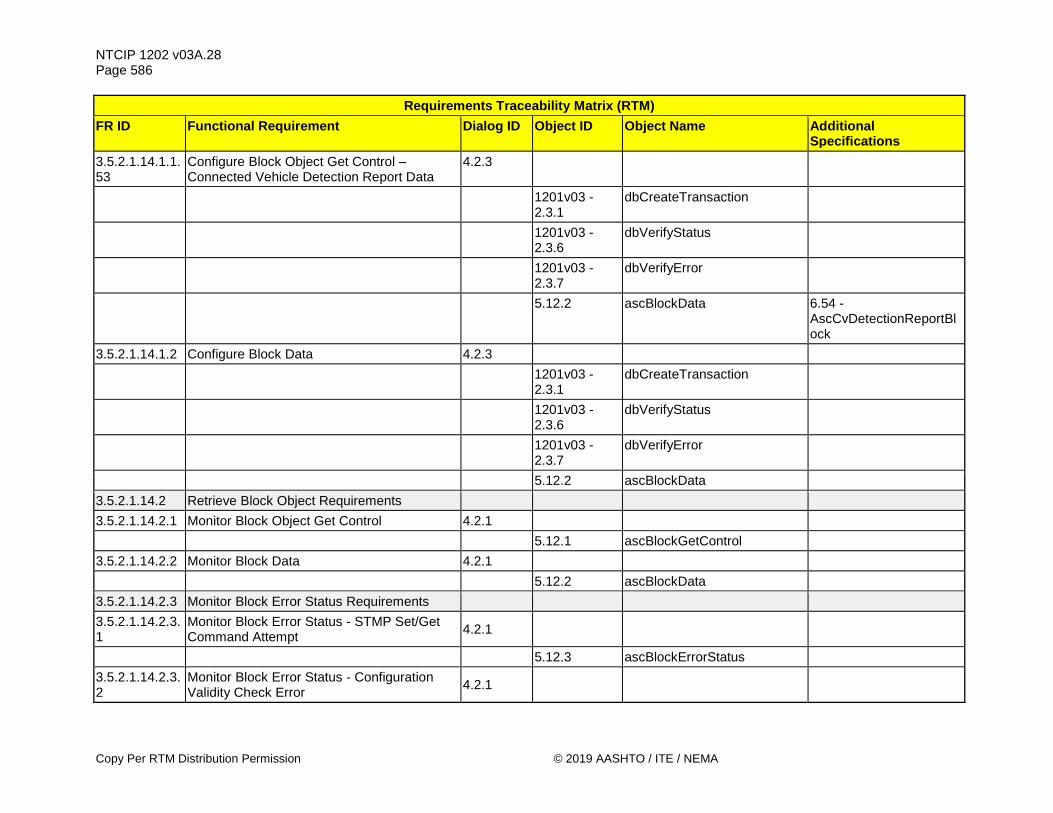
NTCIP 1202 v03A.28 Page 586
Copy Per RTM Distribution Permission © 2019 AASHTO / ITE / NEMA
Requirements Traceability Matrix (RTM) FR ID Functional Requirement Dialog ID Object ID Object Name Additional
Specifications 3.5.2.1.14.1.1.53
Configure Block Object Get Control – Connected Vehicle Detection Report Data
4.2.3
1201v03 - 2.3.1
dbCreateTransaction
1201v03 - 2.3.6
dbVerifyStatus
1201v03 - 2.3.7
dbVerifyError
5.12.2 ascBlockData 6.54 -
AscCvDetectionReportBlock
3.5.2.1.14.1.2 Configure Block Data 4.2.3
1201v03 - 2.3.1
dbCreateTransaction
1201v03 - 2.3.6
dbVerifyStatus
1201v03 - 2.3.7
dbVerifyError
5.12.2 ascBlockData 3.5.2.1.14.2 Retrieve Block Object Requirements 3.5.2.1.14.2.1 Monitor Block Object Get Control 4.2.1 5.12.1 ascBlockGetControl 3.5.2.1.14.2.2 Monitor Block Data 4.2.1 5.12.2 ascBlockData 3.5.2.1.14.2.3 Monitor Block Error Status Requirements 3.5.2.1.14.2.3.1
Monitor Block Error Status - STMP Set/Get Command Attempt 4.2.1
5.12.3 ascBlockErrorStatus 3.5.2.1.14.2.3.2
Monitor Block Error Status - Configuration Validity Check Error 4.2.1
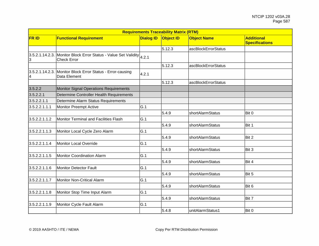
NTCIP 1202 v03A.28 Page 587
© 2019 AASHTO / ITE / NEMA Copy Per RTM Distribution Permission
Requirements Traceability Matrix (RTM) FR ID Functional Requirement Dialog ID Object ID Object Name Additional
Specifications 5.12.3 ascBlockErrorStatus 3.5.2.1.14.2.3.3
Monitor Block Error Status - Value Set Validity Check Error 4.2.1
5.12.3 ascBlockErrorStatus 3.5.2.1.14.2.3.4
Monitor Block Error Status - Error-causing Data Element 4.2.1
5.12.3 ascBlockErrorStatus 3.5.2.2 Monitor Signal Operations Requirements 3.5.2.2.1 Determine Controller Health Requirements 3.5.2.2.1.1 Determine Alarm Status Requirements 3.5.2.2.1.1.1 Monitor Preempt Active G.1 5.4.9 shortAlarmStatus Bit 0 3.5.2.2.1.1.2 Monitor Terminal and Facilities Flash G.1 5.4.9 shortAlarmStatus Bit 1 3.5.2.2.1.1.3 Monitor Local Cycle Zero Alarm G.1 5.4.9 shortAlarmStatus Bit 2 3.5.2.2.1.1.4 Monitor Local Override G.1 5.4.9 shortAlarmStatus Bit 3 3.5.2.2.1.1.5 Monitor Coordination Alarm G.1 5.4.9 shortAlarmStatus Bit 4 3.5.2.2.1.1.6 Monitor Detector Fault G.1 5.4.9 shortAlarmStatus Bit 5 3.5.2.2.1.1.7 Monitor Non-Critical Alarm G.1 5.4.9 shortAlarmStatus Bit 6 3.5.2.2.1.1.8 Monitor Stop Time Input Alarm G.1 5.4.9 shortAlarmStatus Bit 7 3.5.2.2.1.1.9 Monitor Cycle Fault Alarm G.1 5.4.8 unitAlarmStatus1 Bit 0

NTCIP 1202 v03A.28 Page 588
Copy Per RTM Distribution Permission © 2019 AASHTO / ITE / NEMA
Requirements Traceability Matrix (RTM) FR ID Functional Requirement Dialog ID Object ID Object Name Additional
Specifications 3.5.2.2.1.1.10 Monitor Coordination Fault G.1 5.4.8 unitAlarmStatus1 Bit 1 3.5.2.2.1.1.11 Monitor Coordination Fail Alarm G.1 5.4.8 unitAlarmStatus1 Bit 2 3.5.2.2.1.1.12 Monitor Cycle Fail Alarm G.1 5.4.8 unitAlarmStatus1 Bit 3 3.5.2.2.1.1.13 Monitor SMU Flash Alarm G.1 5.4.8 unitAlarmStatus1 Bit 4 3.5.2.2.1.1.14 Monitor Local Flash Alarm G.1 5.4.8 unitAlarmStatus1 Bit 5 3.5.2.2.1.1.15 Monitor Local Free Alarm G.1 5.4.8 unitAlarmStatus1 Bit 6 3.5.2.2.1.1.16 Monitor Coordination Active Alarm G.1 5.4.8 unitAlarmStatus1 Bit 7 3.5.2.2.1.1.17 Monitor Power Restart Alarm G.1 5.4.7 unitAlarmStatus2 Bit 0 3.5.2.2.1.1.18 Monitor Low Battery Alarm G.1 5.4.7 unitAlarmStatus2 Bit 1 3.5.2.2.1.1.19 Monitor Response Fault Alarm G.1 5.4.7 unitAlarmStatus2 Bit 2 3.5.2.2.1.1.20 Monitor External Start G.1 5.4.7 unitAlarmStatus2 Bit 3 3.5.2.2.1.1.21 Monitor Stop Time Alarm G.1 5.4.7 unitAlarmStatus2 Bit 4 3.5.2.2.1.1.22 Monitor Offset Transitioning Alarm G.1 5.4.7 unitAlarmStatus2 Bit 5 3.5.2.2.1.1.23 Monitor Stall Condition G.1 5.4.7 unitAlarmStatus2 Bit 6

NTCIP 1202 v03A.28 Page 589
© 2019 AASHTO / ITE / NEMA Copy Per RTM Distribution Permission
Requirements Traceability Matrix (RTM) FR ID Functional Requirement Dialog ID Object ID Object Name Additional
Specifications 3.5.2.2.1.1.24 Monitor Memory Fault G.1 5.4.27 unitAlarmStatus4 Bit 0 3.5.2.2.1.1.25 Monitor Process Failure G.1 5.4.7 unitAlarmStatus2 Bit 7 3.5.2.2.1.1.26 Monitor Communications Timeout G.1 5.4.26 unitAlarmStatus3 Bit 0 3.5.2.2.1.1.27 Monitor Power Problems G.1 5.4.26 unitAlarmStatus3 Bit 5 3.5.2.2.1.1.28 Monitor UPS Errors G.1 5.4.26 unitAlarmStatus3 Bit 3 3.5.2.2.1.1.29 Monitor Scheduler Errors G.1 5.4.27 unitAlarmStatus4 Bit 4 3.5.2.2.1.1.30 Monitor Signal Monitor Communications Error G.1 5.4.26 unitAlarmStatus3 Bit 2 3.5.2.2.1.1.31 Monitor Signal Monitor Unit Presence G.1 5.4.26 unitAlarmStatus3 Bit 1 3.5.2.2.1.1.32 Monitor USB Memory Device G.1 5.4.27 unitAlarmStatus4 Bit 5 3.5.2.2.1.1.33 Monitor ASC Cabinet Temperature Alarm G.1 5.4.27 unitAlarmStatus4 Bit 2 3.5.2.2.1.1.34 Monitor ASC Cabinet Humidity Alarm G.1 5.4.27 unitAlarmStatus4 Bit 2 3.5.2.2.1.1.35 Monitor Clock Failure G.1 5.4.27 unitAlarmStatus4 Bit 3 3.5.2.2.1.1.36 Monitor Preempt Maximum Presence Alarm G.1 5.4.27 unitAlarmStatus4 Bit 1 3.5.2.2.1.1.37 Monitor RSU Watchdog Timer G.1 5.4.26 unitAlarmStatus3 Bit 4

NTCIP 1202 v03A.28 Page 590
Copy Per RTM Distribution Permission © 2019 AASHTO / ITE / NEMA
Requirements Traceability Matrix (RTM) FR ID Functional Requirement Dialog ID Object ID Object Name Additional
Specifications 3.5.2.2.1.1.38 Monitor CV Certificate Faults G.1 5.4.26 unitAlarmStatus3 Bit 6 3.5.2.2.1.2 Monitor Alarm Group State H.2.5 5.4.11 maxAlarmGroups 5.4.12 alarmGroupTable 5.4.12.1 alarmGroupNumber 5.4.12.2 alarmGroupState 3.5.2.2.2 Retrieve Mode of Operation Requirements 3.5.2.2.2.1 Monitor Unit Control Status G.1 5.4.5 unitControlStatus 3.5.2.2.2.2 Monitor External Minimum Recall G.1 5.4.10 unitControl 3.5.2.2.2.3 Monitor Call to Non-Actuated 1 G.1 5.4.10 unitControl 3.5.2.2.2.4 Monitor Call to Non-Actuated 2 G.1 5.4.10 unitControl 3.5.2.2.2.5 Monitor Walk Rest Modifier G.1 5.4.10 unitControl 3.5.2.2.2.6 Monitor Interconnect G.1 5.4.10 unitControl 3.5.2.2.2.7 Monitor Dimming Enabled G.1 5.4.10 unitControl 3.5.2.2.2.8 Monitor Unit Flash Status G.1 5.4.6 unitFlashStatus 3.5.2.2.2.9 Monitor Current Timing Pattern Requirements 3.5.2.2.2.9.1 Monitor Current Pattern Status G.1 5.5.10 coordPatternStatus 3.5.2.2.2.9.2 Monitor Local Free Status G.1

NTCIP 1202 v03A.28 Page 591
© 2019 AASHTO / ITE / NEMA Copy Per RTM Distribution Permission
Requirements Traceability Matrix (RTM) FR ID Functional Requirement Dialog ID Object ID Object Name Additional
Specifications 5.5.11 localFreeStatus 3.5.2.2.2.9.3 Monitor Current Mode of Operation G.1 5.5.1 coordOperationalMode 3.5.2.2.2.9.4 Monitor Programmed Pattern G.1 5.5.14 systemPatternControl 3.5.2.2.2.10 Monitor Current Cycle Requirements 3.5.2.2.2.10.1 Monitor Coordination Cycle Status G.1 5.5.12 coordCycleStatus 3.5.2.2.2.10.2 Monitor Coordination Synchronization Status G.1 5.5.13 coordSyncStatus 3.5.2.2.2.10.3 Monitor Current Split H.2.5 5.5.5 maxPatterns 5.5.6 patternTableType 5.5.7 patternTable 5.5.7.1 patternNumber 5.5.7.4 patternSplitNumber 5.5.8 maxSplits 5.5.9 splitTable 5.5.9.1 splitNumber 5.5.9.2 splitPhase 5.5.9.3 splitTime 5.5.10 coordPatternStatus 3.5.2.2.2.10.4 Monitor Current Offset H.2.5 5.5.5 maxPatterns 5.5.6 patternTableType 5.5.7 patternTable 5.5.7.1 patternNumber 5.5.7.3 patternOffsetTime

NTCIP 1202 v03A.28 Page 592
Copy Per RTM Distribution Permission © 2019 AASHTO / ITE / NEMA
Requirements Traceability Matrix (RTM) FR ID Functional Requirement Dialog ID Object ID Object Name Additional
Specifications 5.5.14 systemPatternControl
3.5.2.2.3 Monitor Current Signal Indications Requirements
3.5.2.2.3.1 Determine Maximum Number of Phase Groups G.1
5.2.3 maxPhaseGroups 3.5.2.2.3.2 Monitor Phase Group Reds H.2.5 5.2.3 maxPhaseGroups 5.2.4 phaseStatusGroupTable 5.2.4.1 phaseStatusGroupNumber 5.2.4.2 phaseStatusGroupReds 3.5.2.2.3.3 Monitor Phase Group Yellows H.2.5 5.2.3 maxPhaseGroups 5.2.4 phaseStatusGroupTable 5.2.4.1 phaseStatusGroupNumber 5.2.4.3 phaseStatusGroupYellows 3.5.2.2.3.4 Monitor Phase Group Greens H.2.5 5.2.3 maxPhaseGroups 5.2.4 phaseStatusGroupTable 5.2.4.1 phaseStatusGroupNumber 5.2.4.4 phaseStatusGroupGreens 3.5.2.2.3.5 Monitor Phase Group Don't Walks H.2.5 5.2.3 maxPhaseGroups 5.2.4 phaseStatusGroupTable 5.2.4.1 phaseStatusGroupNumber 5.2.4.5 phaseStatusGroupDontWalks 3.5.2.2.3.6 Monitor Phase Group Pedestrian Clearance H.2.5 5.2.3 maxPhaseGroups

NTCIP 1202 v03A.28 Page 593
© 2019 AASHTO / ITE / NEMA Copy Per RTM Distribution Permission
Requirements Traceability Matrix (RTM) FR ID Functional Requirement Dialog ID Object ID Object Name Additional
Specifications 5.2.4 phaseStatusGroupTable 5.2.4.1 phaseStatusGroupNumber 5.2.4.6 phaseStatusGroupPedClears 3.5.2.2.3.7 Monitor Phase Group Walks H.2.5 5.2.3 maxPhaseGroups 5.2.4 phaseStatusGroupTable 5.2.4.1 phaseStatusGroupNumber 5.2.4.7 phaseStatusGroupWalks 3.5.2.2.3.8 Monitor Phase Group Flashing Yellow Arrow H.2.5 5.10.3 maxOverlapStatusGroups 5.10.4 overlapStatusGroupTable 5.10.4.1 overlapStatusGroupNumber
5.10.4.3
overlapStatusGroupYellows Note: whether this object or overlapStatusGroupGreens is used is dependent on where the FYA is wired.
5.10.4.4 overlapStatusGroupGreens 3.5.2.2.3.9 Monitor Phase Group Flashing Red Arrow H.2.5 5.10.3 maxOverlapStatusGroups 5.10.4 overlapStatusGroupTable 5.10.4.1 overlapStatusGroupNumber
5.10.4.2
overlapStatusGroupReds Note: whether this object or overlapStatusGroupGreens is used is dependent on where the FRA is wired.
5.10.4.4 overlapStatusGroupGreens

NTCIP 1202 v03A.28 Page 594
Copy Per RTM Distribution Permission © 2019 AASHTO / ITE / NEMA
Requirements Traceability Matrix (RTM) FR ID Functional Requirement Dialog ID Object ID Object Name Additional
Specifications 3.5.2.2.4 Monitor Current Phase Requirements 3.5.2.2.4.1 Monitor Phase Group Phase Ons H.2.5 5.2.3 maxPhaseGroups 5.2.4 phaseStatusGroupTable 5.2.4.1 phaseStatusGroupNumber 5.2.4.10 phaseStatusGroupPhaseOns 3.5.2.2.4.2 Monitor Phase Group Phase Nexts H.2.5 5.2.3 maxPhaseGroups 5.2.4 phaseStatusGroupTable 5.2.4.1 phaseStatusGroupNumber
5.2.4.11 phaseStatusGroupPhaseNexts
3.5.2.2.4.3 Monitor Phase Group Vehicle Call H.2.5 5.2.3 maxPhaseGroups 5.2.4 phaseStatusGroupTable 5.2.4.1 phaseStatusGroupNumber 5.2.4.8 phaseStatusGroupVehCalls 3.5.2.2.4.4 Monitor Phase Group Pedestrian Call H.2.5 5.2.3 maxPhaseGroups 5.2.4 phaseStatusGroupTable 5.2.4.1 phaseStatusGroupNumber 5.2.4.9 phaseStatusGroupPedCalls 3.5.2.2.4.5 Monitor Phase Group Bicycle Call H.2.5 5.2.3 maxPhaseGroups 5.2.4 phaseStatusGroupTable 5.2.4.1 phaseStatusGroupNumber 5.2.4.8 phaseStatusGroupVehCalls 3.5.2.2.4.6 Monitor Phase Group Transit Call H.2.5

NTCIP 1202 v03A.28 Page 595
© 2019 AASHTO / ITE / NEMA Copy Per RTM Distribution Permission
Requirements Traceability Matrix (RTM) FR ID Functional Requirement Dialog ID Object ID Object Name Additional
Specifications 5.2.3 maxPhaseGroups 5.2.4 phaseStatusGroupTable 5.2.4.1 phaseStatusGroupNumber 5.2.4.8 phaseStatusGroupVehCalls 3.5.2.2.5 Retrieve Current Ring Requirements 3.5.2.2.5.1 Monitor Ring Status H.2.5 5.8.1 maxRings 5.8.6 ringStatusTable 5.8.6.1 ringStatus 3.5.2.2.5.2 Monitor Ring Termination Cause H.2.5 5.8.1 maxRings 5.8.6 ringStatusTable 5.8.6.1 ringStatus
3.5.2.2.6 Retrieve Current Channel Status Requirements
3.5.2.2.6.1 Determine Maximum Number of Channel Status Groups G.1
5.9.3 maxChannelStatusGroups 3.5.2.2.6.2 Monitor Channel Status Group Reds H.2.5 5.9.3 maxChannelStatusGroups 5.9.4 channelStatusGroupTable 5.9.4.1 channelStatusGroupNumber 5.9.4.2 channelStatusGroupReds 3.5.2.2.6.3 Monitor Channel Status Group Yellows H.2.5 5.9.3 maxChannelStatusGroups 5.9.4 channelStatusGroupTable 5.9.4.1 channelStatusGroupNumber 5.9.4.3 channelStatusGroupYellows

NTCIP 1202 v03A.28 Page 596
Copy Per RTM Distribution Permission © 2019 AASHTO / ITE / NEMA
Requirements Traceability Matrix (RTM) FR ID Functional Requirement Dialog ID Object ID Object Name Additional
Specifications 3.5.2.2.6.4 Monitor Channel Status Group Greens H.2.5 5.9.3 maxChannelStatusGroups 5.9.4 channelStatusGroupTable 5.9.4.1 channelStatusGroupNumber 5.9.4.4 channelStatusGroupGreens
3.5.2.2.7 Retrieve Current Overlap Status Requirements
3.5.2.2.7.1 Determine Maximum Number of Overlap Status Groups G.1
5.10.3 maxOverlapStatusGroups 3.5.2.2.7.2 Monitor Overlap Status Group Reds H.2.5 5.10.3 maxOverlapStatusGroups 5.10.4 overlapStatusGroupTable 5.10.4.1 overlapStatusGroupNumber 5.10.4.2 overlapStatusGroupReds 3.5.2.2.7.3 Monitor Overlap Status Group Yellows H.2.5 5.10.3 maxOverlapStatusGroups 5.10.4 overlapStatusGroupTable 5.10.4.1 overlapStatusGroupNumber 5.10.4.3 overlapStatusGroupYellows 3.5.2.2.7.4 Monitor Overlap Status Group Greens H.2.5 5.10.3 maxOverlapStatusGroups 5.10.4 overlapStatusGroupTable 5.10.4.1 overlapStatusGroupNumber 5.10.4.4 overlapStatusGroupGreens
3.5.2.2.7.5 Monitor Overlap Status Group Flashing Yellow Arrows H.2.5
5.10.3 maxOverlapStatusGroups
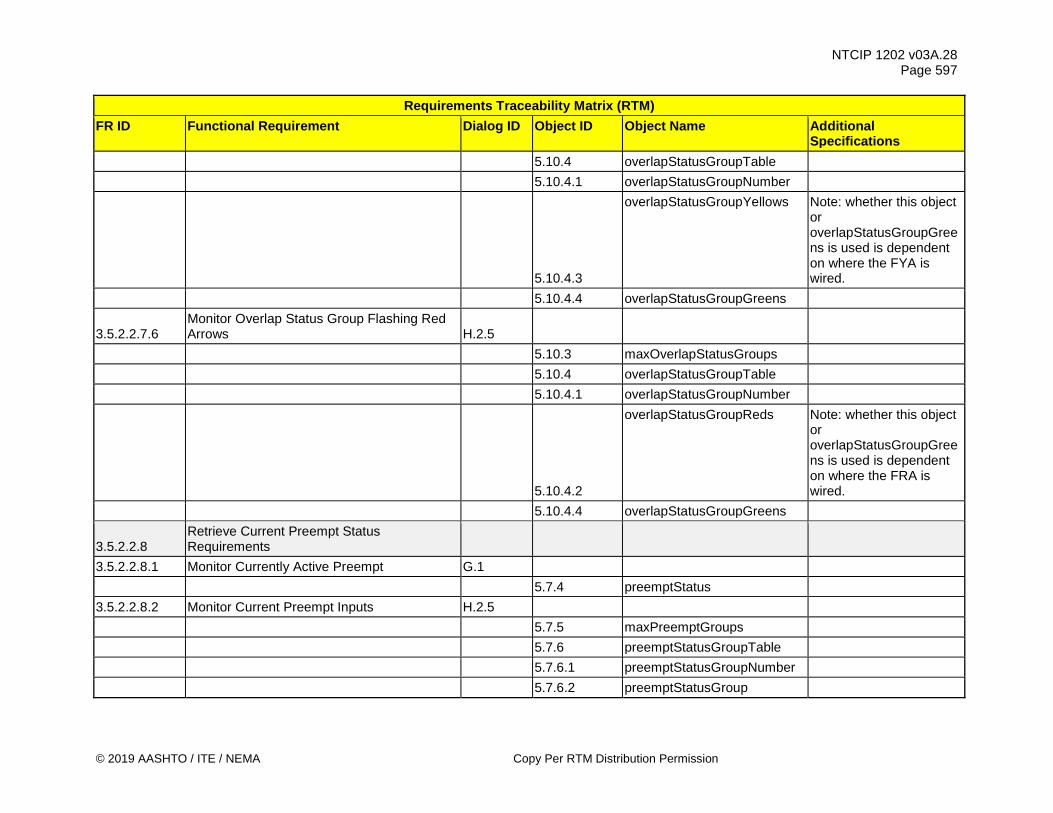
NTCIP 1202 v03A.28 Page 597
© 2019 AASHTO / ITE / NEMA Copy Per RTM Distribution Permission
Requirements Traceability Matrix (RTM) FR ID Functional Requirement Dialog ID Object ID Object Name Additional
Specifications 5.10.4 overlapStatusGroupTable 5.10.4.1 overlapStatusGroupNumber
5.10.4.3
overlapStatusGroupYellows Note: whether this object or overlapStatusGroupGreens is used is dependent on where the FYA is wired.
5.10.4.4 overlapStatusGroupGreens
3.5.2.2.7.6 Monitor Overlap Status Group Flashing Red Arrows H.2.5
5.10.3 maxOverlapStatusGroups 5.10.4 overlapStatusGroupTable 5.10.4.1 overlapStatusGroupNumber
5.10.4.2
overlapStatusGroupReds Note: whether this object or overlapStatusGroupGreens is used is dependent on where the FRA is wired.
5.10.4.4 overlapStatusGroupGreens
3.5.2.2.8 Retrieve Current Preempt Status Requirements
3.5.2.2.8.1 Monitor Currently Active Preempt G.1 5.7.4 preemptStatus 3.5.2.2.8.2 Monitor Current Preempt Inputs H.2.5 5.7.5 maxPreemptGroups 5.7.6 preemptStatusGroupTable 5.7.6.1 preemptStatusGroupNumber 5.7.6.2 preemptStatusGroup

NTCIP 1202 v03A.28 Page 598
Copy Per RTM Distribution Permission © 2019 AASHTO / ITE / NEMA
Requirements Traceability Matrix (RTM) FR ID Functional Requirement Dialog ID Object ID Object Name Additional
Specifications 3.5.2.2.8.3 Monitor Current Preempt State H.2.5 5.7.1 maxPreempts 5.7.2 preemptTable 5.7.2.1 preemptNumber 5.7.2.16 preemptState 3.5.2.2.8.4 Monitor Current Gate Status H.2.5 5.7.8 maxPreemptGates 5.7.9 preemptGateTable 5.7.9.1 preemptGateNumber 5.7.9.2 preemptGateStatus 5.7.9.3 preemptGateDescription
3.5.2.2.9 Retrieve Special Function Outputs Requirements
3.5.2.2.9.1 Determine Maximum Number of Special Functions G.1
5.4.13 maxSpecialFunctionOutputs 3.5.2.2.9.2 Monitor Special Function State DEPRECATED 3.5.2.2.9.3 Monitor Special Function Status H.2.5 5.4.13 maxSpecialFunctionOutputs 5.4.14 specialFunctionOutputTable 5.4.14.1 specialFunctionOutputNumber 5.4.14.4 specialFunctionOutputStatus 3.5.2.2.9.4 Monitor Special Function Control Source G.1 5.4.13 maxSpecialFunctionOutputs 5.4.14 specialFunctionOutputTable 5.4.14.1 specialFunctionOutputNumber 5.4.14.3 specialFunctionOutputControl
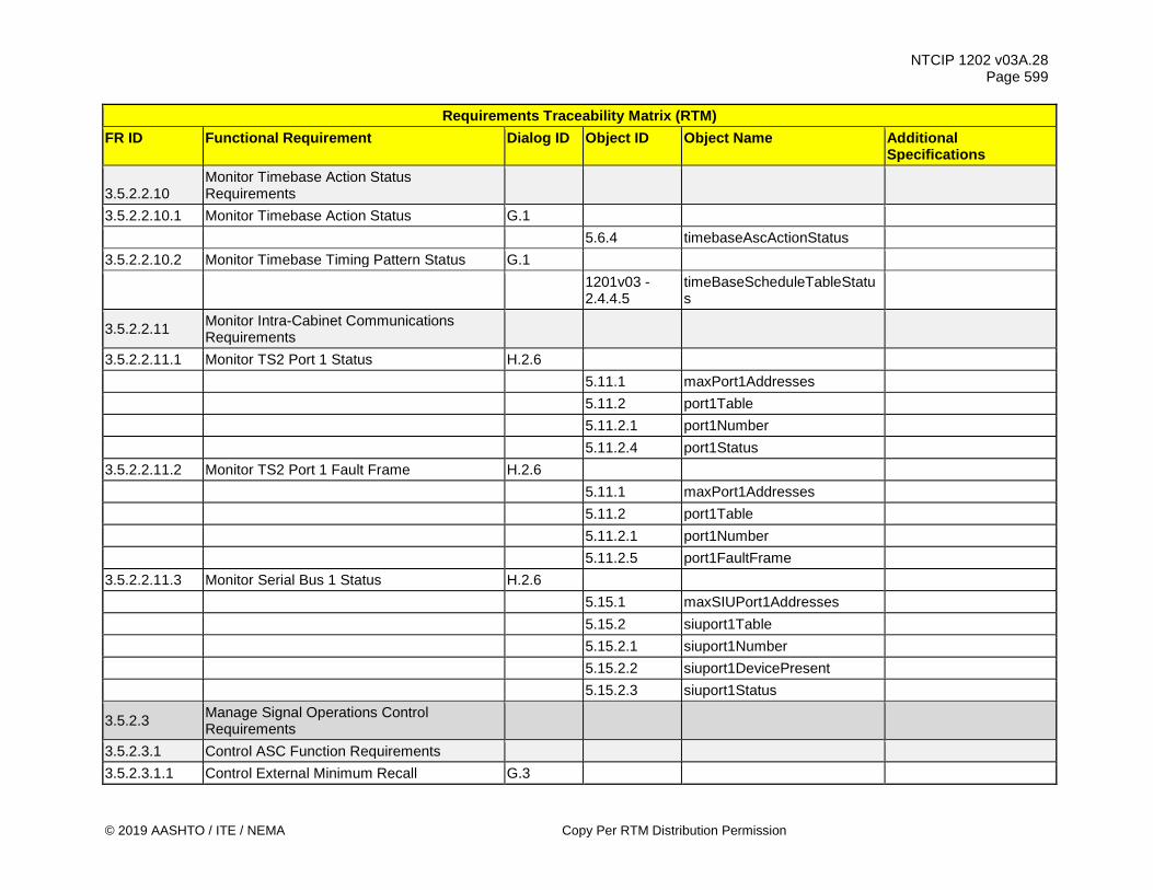
NTCIP 1202 v03A.28 Page 599
© 2019 AASHTO / ITE / NEMA Copy Per RTM Distribution Permission
Requirements Traceability Matrix (RTM) FR ID Functional Requirement Dialog ID Object ID Object Name Additional
Specifications
3.5.2.2.10 Monitor Timebase Action Status Requirements
3.5.2.2.10.1 Monitor Timebase Action Status G.1 5.6.4 timebaseAscActionStatus 3.5.2.2.10.2 Monitor Timebase Timing Pattern Status G.1
1201v03 - 2.4.4.5
timeBaseScheduleTableStatus
3.5.2.2.11 Monitor Intra-Cabinet Communications Requirements
3.5.2.2.11.1 Monitor TS2 Port 1 Status H.2.6 5.11.1 maxPort1Addresses 5.11.2 port1Table 5.11.2.1 port1Number 5.11.2.4 port1Status 3.5.2.2.11.2 Monitor TS2 Port 1 Fault Frame H.2.6 5.11.1 maxPort1Addresses 5.11.2 port1Table 5.11.2.1 port1Number 5.11.2.5 port1FaultFrame 3.5.2.2.11.3 Monitor Serial Bus 1 Status H.2.6 5.15.1 maxSIUPort1Addresses 5.15.2 siuport1Table 5.15.2.1 siuport1Number 5.15.2.2 siuport1DevicePresent 5.15.2.3 siuport1Status
3.5.2.3 Manage Signal Operations Control Requirements
3.5.2.3.1 Control ASC Function Requirements 3.5.2.3.1.1 Control External Minimum Recall G.3

NTCIP 1202 v03A.28 Page 600
Copy Per RTM Distribution Permission © 2019 AASHTO / ITE / NEMA
Requirements Traceability Matrix (RTM) FR ID Functional Requirement Dialog ID Object ID Object Name Additional
Specifications 5.4.10 unitControl Bit 2 3.5.2.3.1.2 Control Call to Non-Actuated 1 G.3 5.4.10 unitControl Bit 3 3.5.2.3.1.3 Control Call to Non-Actuated 2 G.3 5.4.10 unitControl Bit 4 3.5.2.3.1.4 Control Walk Rest Modifier G.3 5.4.10 unitControl Bit 5 3.5.2.3.1.5 Control Interconnect G.3 5.4.10 unitControl Bit 6 3.5.2.3.1.6 Control Dimming Enabled G.3 5.4.10 unitControl Bit 7 3.5.2.3.1.7 Control Disable Remote Commands G.3 5.4.10 unitControl Bit 1 3.5.2.3.1.8 Acknowledge Local Cycle Zero Alarm G.1 5.4.9 shortAlarmStatus Bit 2
3.5.2.3.1.9 Control Weather-based Signal Operation Changes G.3
5.5.14 systemPatternControl 3.5.2.3.2 Command Timing Pattern Requirements 3.5.2.3.2.1 Command System Timing Pattern G.3 5.5.14 systemPatternControl
3.5.2.3.2.2 Command System Timing Pattern System Reference Point G.3
5.5.15 systemSyncControl 3.5.2.3.3 Control Phases Requirements 3.5.2.3.3.1 Control Phase Group Phase Omits H.2.7 5.2.3 maxPhaseGroups 5.2.5 phaseControlGroupTable

NTCIP 1202 v03A.28 Page 601
© 2019 AASHTO / ITE / NEMA Copy Per RTM Distribution Permission
Requirements Traceability Matrix (RTM) FR ID Functional Requirement Dialog ID Object ID Object Name Additional
Specifications 5.2.5.1 phaseControlGroupNumber
5.2.5.2 phaseControlGroupPhaseOmit
3.5.2.3.3.2 Control Phase Group Pedestrian Omits H.2.7 5.2.3 maxPhaseGroups 5.2.5 phaseControlGroupTable 5.2.5.1 phaseControlGroupNumber 5.2.5.3 phaseControlGroupPedOmit 3.5.2.3.3.3 Control Phase Group Holds H.2.7 5.2.3 maxPhaseGroups 5.2.5 phaseControlGroupTable 5.2.5.1 phaseControlGroupNumber 5.2.5.4 phaseControlGroupHold 3.5.2.3.3.4 Control Phase Group Force Offs H.2.7 5.2.3 maxPhaseGroups 5.2.5 phaseControlGroupTable 5.2.5.1 phaseControlGroupNumber 5.2.5.5 phaseControlGroupForceOff 3.5.2.3.3.5 Control Phase Group Vehicle Calls H.2.7 5.2.3 maxPhaseGroups 5.2.5 phaseControlGroupTable 5.2.5.1 phaseControlGroupNumber 5.2.5.6 phaseControlGroupVehCall 3.5.2.3.3.6 Control Phase Group Pedestrian Calls H.2.7 5.2.3 maxPhaseGroups 5.2.5 phaseControlGroupTable 5.2.5.1 phaseControlGroupNumber 5.2.5.7 phaseControlGroupPedCall

NTCIP 1202 v03A.28 Page 602
Copy Per RTM Distribution Permission © 2019 AASHTO / ITE / NEMA
Requirements Traceability Matrix (RTM) FR ID Functional Requirement Dialog ID Object ID Object Name Additional
Specifications 3.5.2.3.3.7 Control Phase Group Bicycle Calls H.2.7 5.2.3 maxPhaseGroups 5.2.5 phaseControlGroupTable 5.2.5.1 phaseControlGroupNumber 5.2.5.6 phaseControlGroupVehCall 3.5.2.3.3.8 Control Phase Group Transit Calls H.2.7 5.2.3 maxPhaseGroups 5.2.5 phaseControlGroupTable 5.2.5.1 phaseControlGroupNumber 5.2.5.6 phaseControlGroupVehCall 3.5.2.3.4 Control Preempt Requirements 3.5.2.3.4.1 Command Preempt Remote Activation H.2.7 5.7.3 preemptControlTable 5.7.3.1 preemptControlNumber 5.7.3.2 preemptControlState 3.5.2.3.5 Control Ring Requirements 3.5.2.3.5.1 Control Ring Stop Time H.2.7 5.8.5 ringControlGroupTable 5.8.5.1 ringControlGroupNumber 5.8.5.2 ringControlGroupStopTime 3.5.2.3.5.2 Control Ring Force Offs H.2.7 5.8.5 ringControlGroupTable 5.8.5.1 ringControlGroupNumber 5.8.5.3 ringControlGroupForceOff 3.5.2.3.5.3 Control Ring Maximum 2 Time Settings H.2.7 5.8.5 ringControlGroupTable 5.8.5.1 ringControlGroupNumber 5.8.5.4 ringControlGroupMax2
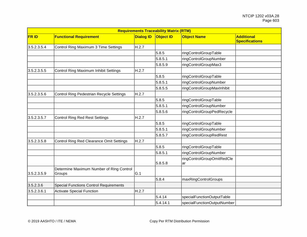
NTCIP 1202 v03A.28 Page 603
© 2019 AASHTO / ITE / NEMA Copy Per RTM Distribution Permission
Requirements Traceability Matrix (RTM) FR ID Functional Requirement Dialog ID Object ID Object Name Additional
Specifications 3.5.2.3.5.4 Control Ring Maximum 3 Time Settings H.2.7 5.8.5 ringControlGroupTable 5.8.5.1 ringControlGroupNumber 5.8.5.9 ringControlGroupMax3 3.5.2.3.5.5 Control Ring Maximum Inhibit Settings H.2.7 5.8.5 ringControlGroupTable 5.8.5.1 ringControlGroupNumber 5.8.5.5 ringControlGroupMaxInhibit 3.5.2.3.5.6 Control Ring Pedestrian Recycle Settings H.2.7 5.8.5 ringControlGroupTable 5.8.5.1 ringControlGroupNumber 5.8.5.6 ringControlGroupPedRecycle 3.5.2.3.5.7 Control Ring Red Rest Settings H.2.7 5.8.5 ringControlGroupTable 5.8.5.1 ringControlGroupNumber 5.8.5.7 ringControlGroupRedRest 3.5.2.3.5.8 Control Ring Red Clearance Omit Settings H.2.7 5.8.5 ringControlGroupTable 5.8.5.1 ringControlGroupNumber
5.8.5.8 ringControlGroupOmitRedClear
3.5.2.3.5.9 Determine Maximum Number of Ring Control Groups G.1
5.8.4 maxRingControlGroups 3.5.2.3.6 Special Functions Control Requirements 3.5.2.3.6.1 Activate Special Function H.2.7 5.4.14 specialFunctionOutputTable 5.4.14.1 specialFunctionOutputNumber
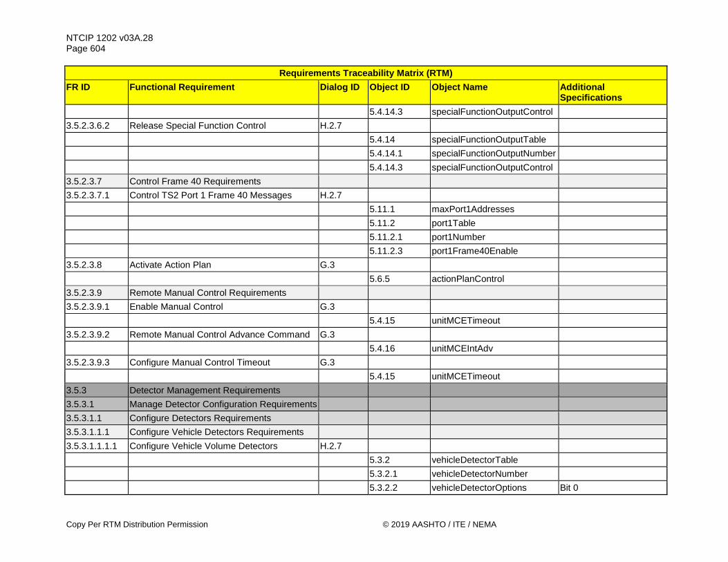
NTCIP 1202 v03A.28 Page 604
Copy Per RTM Distribution Permission © 2019 AASHTO / ITE / NEMA
Requirements Traceability Matrix (RTM) FR ID Functional Requirement Dialog ID Object ID Object Name Additional
Specifications 5.4.14.3 specialFunctionOutputControl 3.5.2.3.6.2 Release Special Function Control H.2.7 5.4.14 specialFunctionOutputTable 5.4.14.1 specialFunctionOutputNumber 5.4.14.3 specialFunctionOutputControl 3.5.2.3.7 Control Frame 40 Requirements 3.5.2.3.7.1 Control TS2 Port 1 Frame 40 Messages H.2.7 5.11.1 maxPort1Addresses 5.11.2 port1Table 5.11.2.1 port1Number 5.11.2.3 port1Frame40Enable 3.5.2.3.8 Activate Action Plan G.3 5.6.5 actionPlanControl 3.5.2.3.9 Remote Manual Control Requirements 3.5.2.3.9.1 Enable Manual Control G.3 5.4.15 unitMCETimeout 3.5.2.3.9.2 Remote Manual Control Advance Command G.3 5.4.16 unitMCEIntAdv 3.5.2.3.9.3 Configure Manual Control Timeout G.3 5.4.15 unitMCETimeout 3.5.3 Detector Management Requirements 3.5.3.1 Manage Detector Configuration Requirements 3.5.3.1.1 Configure Detectors Requirements 3.5.3.1.1.1 Configure Vehicle Detectors Requirements 3.5.3.1.1.1.1 Configure Vehicle Volume Detectors H.2.7 5.3.2 vehicleDetectorTable 5.3.2.1 vehicleDetectorNumber 5.3.2.2 vehicleDetectorOptions Bit 0

NTCIP 1202 v03A.28 Page 605
© 2019 AASHTO / ITE / NEMA Copy Per RTM Distribution Permission
Requirements Traceability Matrix (RTM) FR ID Functional Requirement Dialog ID Object ID Object Name Additional
Specifications 3.5.3.1.1.1.2 Configure Vehicle Occupancy Detectors H.2.7 5.3.2 vehicleDetectorTable 5.3.2.1 vehicleDetectorNumber 5.3.2.2 vehicleDetectorOptions Bit 1 3.5.3.1.1.1.3 Configure Vehicle Speed Detectors H.2.7 5.3.2 vehicleDetectorTable 5.3.2.1 vehicleDetectorNumber 5.3.2.15 vehicleDetectorOptions2 Bit 0 3.5.3.1.1.1.4 Configure Vehicle Detection Zone Length H.2.7 5.3.2 vehicleDetectorTable 5.3.2.1 vehicleDetectorNumber 5.3.2.19 vehicleDetectorLength 3.5.3.1.1.1.5 Configure Vehicle Travel Mode H.2.7 5.3.2 vehicleDetectorTable 5.3.2.1 vehicleDetectorNumber 5.3.2.20 vehicleDetectorTravelMode
3.5.3.1.1.1.6 Configure Vehicle Detector Yellow Lock Call Enabled H.2.7
5.3.2 vehicleDetectorTable 5.3.2.1 vehicleDetectorNumber 5.3.2.2 vehicleDetectorOptions Bit 2
3.5.3.1.1.1.7 Configure Vehicle Detector Red Lock Call Enabled H.2.7
5.3.2 vehicleDetectorTable 5.3.2.1 vehicleDetectorNumber 5.3.2.2 vehicleDetectorOptions Bit 3 3.5.3.1.1.1.8 Configure Vehicle Detector Passage Enabled H.2.7 5.3.2 vehicleDetectorTable

NTCIP 1202 v03A.28 Page 606
Copy Per RTM Distribution Permission © 2019 AASHTO / ITE / NEMA
Requirements Traceability Matrix (RTM) FR ID Functional Requirement Dialog ID Object ID Object Name Additional
Specifications 5.3.2.1 vehicleDetectorNumber 5.3.2.2 vehicleDetectorOptions Bit 4
3.5.3.1.1.1.9 Configure Vehicle Detector Added Initial Time Enabled H.2.7
5.3.2 vehicleDetectorTable 5.3.2.1 vehicleDetectorNumber 5.3.2.2 vehicleDetectorOptions Bit 5 3.5.3.1.1.1.10 Configure Vehicle Detector Queue Enabled H.2.7 5.3.2 vehicleDetectorTable 5.3.2.1 vehicleDetectorNumber 5.3.2.2 vehicleDetectorOptions Bit 6 3.5.3.1.1.1.11 Configure Vehicle Detector Call Enabled H.2.7 5.3.2 vehicleDetectorTable 5.3.2.1 vehicleDetectorNumber 5.3.2.2 vehicleDetectorOptions Bit 7 3.5.3.1.1.1.12 Configure Vehicle Detector Call Phase H.2.7 5.3.2 vehicleDetectorTable 5.3.2.1 vehicleDetectorNumber 5.3.2.3 vehicleDetectorCallPhase 3.5.3.1.1.1.13 Configure Vehicle Detector Switch Phase H.2.7 5.3.2 vehicleDetectorTable 5.3.2.1 vehicleDetectorNumber 5.3.2.4 vehicleDetectorSwitchPhase 3.5.3.1.1.1.14 Configure Vehicle Detector Delay Time H.2.7 5.3.2 vehicleDetectorTable 5.3.2.1 vehicleDetectorNumber 5.3.2.5 vehicleDetectorDelay 3.5.3.1.1.1.15 Configure Vehicle Detector Extend Time H.2.7

NTCIP 1202 v03A.28 Page 607
© 2019 AASHTO / ITE / NEMA Copy Per RTM Distribution Permission
Requirements Traceability Matrix (RTM) FR ID Functional Requirement Dialog ID Object ID Object Name Additional
Specifications 5.3.2 vehicleDetectorTable 5.3.2.1 vehicleDetectorNumber 5.3.2.6 vehicleDetectorExtend 3.5.3.1.1.1.16 Configure Vehicle Detector Queue Limit Time H.2.7 5.3.2 vehicleDetectorTable 5.3.2.1 vehicleDetectorNumber 5.3.2.7 vehicleDetectorQueueLimit 3.5.3.1.1.1.17 Configure Vehicle Detector No Activity Time H.2.7 5.3.2 vehicleDetectorTable 5.3.2.1 vehicleDetectorNumber 5.3.2.8 vehicleDetectorNoActivity
3.5.3.1.1.1.18 Configure Vehicle Detector Maximum Presence Time H.2.7
5.3.2 vehicleDetectorTable 5.3.2.1 vehicleDetectorNumber 5.3.2.9 vehicleDetectorMaxPresence 3.5.3.1.1.1.19 Configure Vehicle Detector Erratic Counts H.2.7 5.3.2 vehicleDetectorTable 5.3.2.1 vehicleDetectorNumber 5.3.2.10 vehicleDetectorErraticCounts 3.5.3.1.1.1.20 Configure Vehicle Detector Fail Time H.2.7 5.3.2 vehicleDetectorTable 5.3.2.1 vehicleDetectorNumber 5.3.2.11 vehicleDetectorFailTime 3.5.3.1.1.1.21 Configure Single Detector Speed Mode H.2.7 5.3.2 vehicleDetectorTable 5.3.2.1 vehicleDetectorNumber 5.3.2.15 vehicleDetectorOptions2 Bit 2
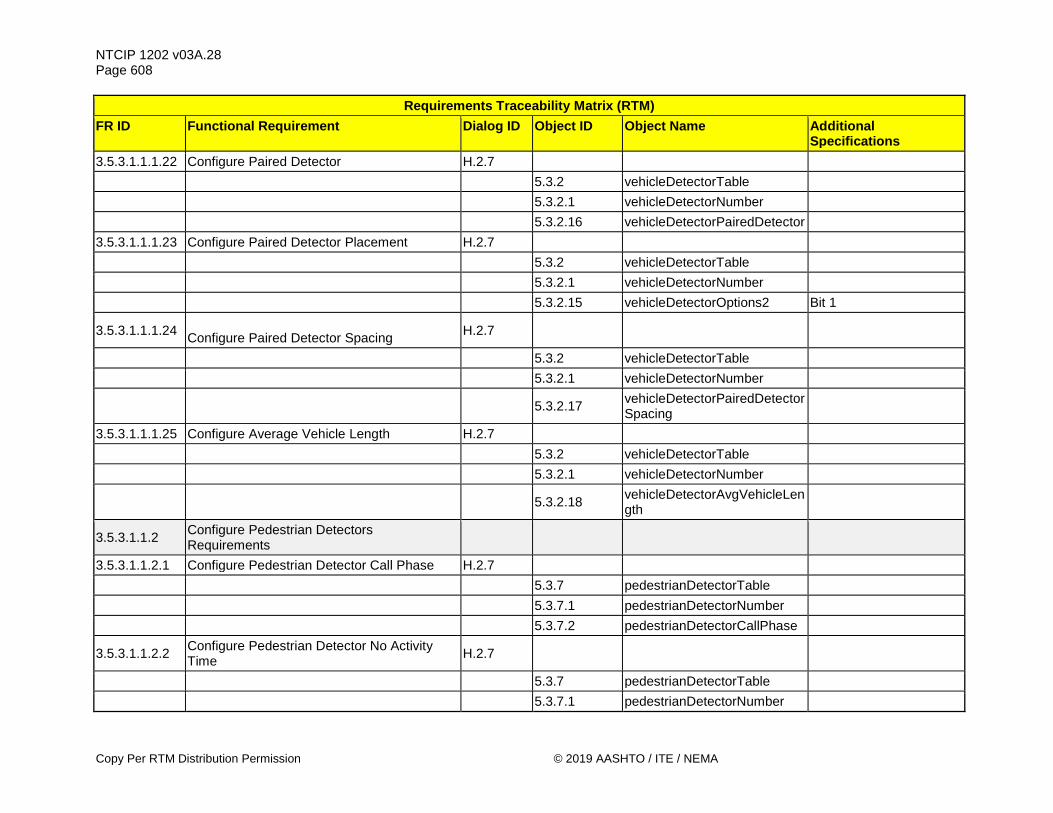
NTCIP 1202 v03A.28 Page 608
Copy Per RTM Distribution Permission © 2019 AASHTO / ITE / NEMA
Requirements Traceability Matrix (RTM) FR ID Functional Requirement Dialog ID Object ID Object Name Additional
Specifications 3.5.3.1.1.1.22 Configure Paired Detector H.2.7 5.3.2 vehicleDetectorTable 5.3.2.1 vehicleDetectorNumber 5.3.2.16 vehicleDetectorPairedDetector 3.5.3.1.1.1.23 Configure Paired Detector Placement H.2.7 5.3.2 vehicleDetectorTable 5.3.2.1 vehicleDetectorNumber 5.3.2.15 vehicleDetectorOptions2 Bit 1
3.5.3.1.1.1.24 Configure Paired Detector Spacing H.2.7
5.3.2 vehicleDetectorTable 5.3.2.1 vehicleDetectorNumber
5.3.2.17 vehicleDetectorPairedDetectorSpacing
3.5.3.1.1.1.25 Configure Average Vehicle Length H.2.7 5.3.2 vehicleDetectorTable 5.3.2.1 vehicleDetectorNumber
5.3.2.18 vehicleDetectorAvgVehicleLength
3.5.3.1.1.2 Configure Pedestrian Detectors Requirements
3.5.3.1.1.2.1 Configure Pedestrian Detector Call Phase H.2.7 5.3.7 pedestrianDetectorTable 5.3.7.1 pedestrianDetectorNumber 5.3.7.2 pedestrianDetectorCallPhase
3.5.3.1.1.2.2 Configure Pedestrian Detector No Activity Time H.2.7
5.3.7 pedestrianDetectorTable 5.3.7.1 pedestrianDetectorNumber
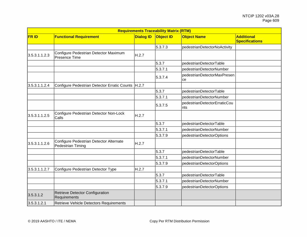
NTCIP 1202 v03A.28 Page 609
© 2019 AASHTO / ITE / NEMA Copy Per RTM Distribution Permission
Requirements Traceability Matrix (RTM) FR ID Functional Requirement Dialog ID Object ID Object Name Additional
Specifications 5.3.7.3 pedestrianDetectorNoActivity
3.5.3.1.1.2.3 Configure Pedestrian Detector Maximum Presence Time H.2.7
5.3.7 pedestrianDetectorTable 5.3.7.1 pedestrianDetectorNumber
5.3.7.4 pedestrianDetectorMaxPresence
3.5.3.1.1.2.4 Configure Pedestrian Detector Erratic Counts H.2.7 5.3.7 pedestrianDetectorTable 5.3.7.1 pedestrianDetectorNumber
5.3.7.5 pedestrianDetectorErraticCounts
3.5.3.1.1.2.5 Configure Pedestrian Detector Non-Lock Calls H.2.7
5.3.7 pedestrianDetectorTable 5.3.7.1 pedestrianDetectorNumber 5.3.7.9 pedestrianDetectorOptions
3.5.3.1.1.2.6 Configure Pedestrian Detector Alternate Pedestrian Timing H.2.7
5.3.7 pedestrianDetectorTable 5.3.7.1 pedestrianDetectorNumber 5.3.7.9 pedestrianDetectorOptions 3.5.3.1.1.2.7 Configure Pedestrian Detector Type H.2.7 5.3.7 pedestrianDetectorTable 5.3.7.1 pedestrianDetectorNumber 5.3.7.9 pedestrianDetectorOptions
3.5.3.1.2 Retrieve Detector Configuration Requirements
3.5.3.1.2.1 Retrieve Vehicle Detectors Requirements

NTCIP 1202 v03A.28 Page 610
Copy Per RTM Distribution Permission © 2019 AASHTO / ITE / NEMA
Requirements Traceability Matrix (RTM) FR ID Functional Requirement Dialog ID Object ID Object Name Additional
Specifications
3.5.3.1.2.1.1 Determine Maximum Number of Vehicle Detectors G.1
5.3.1 maxVehicleDetectors 3.5.3.1.2.2 Retrieve Pedestrian Detectors Requirements
3.5.3.1.2.2.1 Determine Maximum Number of Pedestrian Detectors G.1
5.3.6 maxPedestrianDetectors 3.5.3.2 Retrieve Detector Status Requirements
3.5.3.2.1 Monitor Vehicle Detector Status Groups Requirements
3.5.3.2.1.1 Determine Maximum Number of Vehicle Detector Status Groups G.1
5.3.3 maxVehicleDetectorStatusGroups
3.5.3.2.1.2 Monitor Vehicle Detector Status Group Active H.2.5
5.3.3 maxVehicleDetectorStatusGroups
5.3.4 vehicleDetectorStatusGroupTable
5.3.4.1 vehicleDetectorStatusGroupNumber
5.3.4.2 vehicleDetectorStatusGroupActive
5.3.2.12 vehicleDetectorAlarms
3.5.3.2.1.3 Monitor Vehicle Detector Status Group Alarm Status H.2.5
5.3.3 maxVehicleDetectorStatusGroups
5.3.4 vehicleDetectorStatusGroupTable

NTCIP 1202 v03A.28 Page 611
© 2019 AASHTO / ITE / NEMA Copy Per RTM Distribution Permission
Requirements Traceability Matrix (RTM) FR ID Functional Requirement Dialog ID Object ID Object Name Additional
Specifications
5.3.4.1 vehicleDetectorStatusGroupNumber
5.3.4.3 vehicleDetectorStatusGroupAlarms
5.3.2.12 vehicleDetectorAlarms
3.5.3.2.2 Monitor Pedestrian Detector Status Requirements
3.5.3.2.2.1 Determine Maximum Number of Pedestrian Detector Status Groups G.1
5.3.8 maxPedestrianDetectorGroups
3.5.3.2.2.2 Monitor Pedestrian Detector Status Active H.2.5
5.3.8 maxPedestrianDetectorGroups
5.3.9 pedestrianDetectorStatusGroupTable
5.3.9.1 pedestrianDetectorStatusGroupNumber
5.3.9.2 pedestrianDetectorStatusGroupActive
3.5.3.2.2.3 Monitor Pedestrian Detector Alarm Status H.2.5
5.3.8 maxPedestrianDetectorGroups
5.3.9 pedestrianDetectorStatusGroupTable
5.3.9.1 pedestrianDetectorStatusGroupNumber
5.3.9.3 pedestrianDetectorStatusGroupAlarms
3.5.3.3 Retrieve Detector Health Requirements
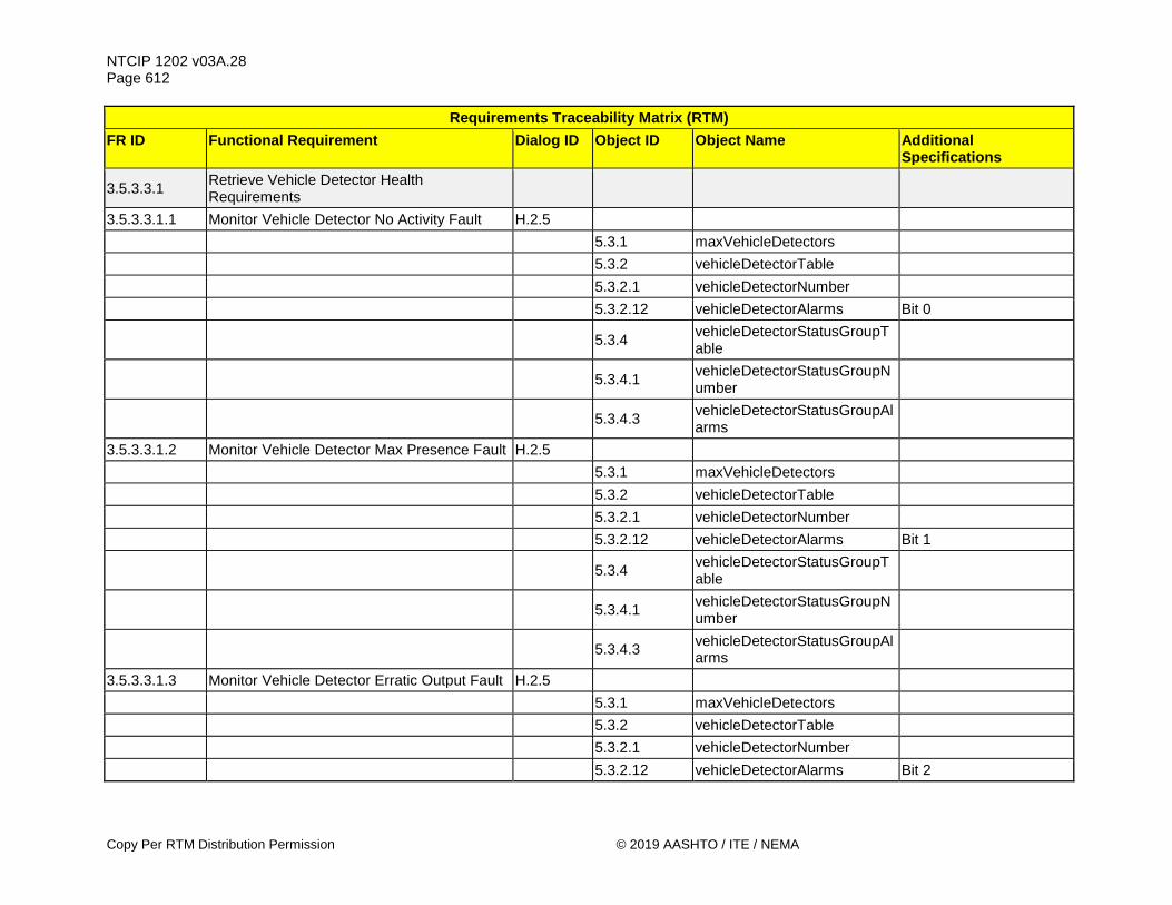
NTCIP 1202 v03A.28 Page 612
Copy Per RTM Distribution Permission © 2019 AASHTO / ITE / NEMA
Requirements Traceability Matrix (RTM) FR ID Functional Requirement Dialog ID Object ID Object Name Additional
Specifications
3.5.3.3.1 Retrieve Vehicle Detector Health Requirements
3.5.3.3.1.1 Monitor Vehicle Detector No Activity Fault H.2.5 5.3.1 maxVehicleDetectors 5.3.2 vehicleDetectorTable 5.3.2.1 vehicleDetectorNumber 5.3.2.12 vehicleDetectorAlarms Bit 0
5.3.4 vehicleDetectorStatusGroupTable
5.3.4.1 vehicleDetectorStatusGroupNumber
5.3.4.3 vehicleDetectorStatusGroupAlarms
3.5.3.3.1.2 Monitor Vehicle Detector Max Presence Fault H.2.5 5.3.1 maxVehicleDetectors 5.3.2 vehicleDetectorTable 5.3.2.1 vehicleDetectorNumber 5.3.2.12 vehicleDetectorAlarms Bit 1
5.3.4 vehicleDetectorStatusGroupTable
5.3.4.1 vehicleDetectorStatusGroupNumber
5.3.4.3 vehicleDetectorStatusGroupAlarms
3.5.3.3.1.3 Monitor Vehicle Detector Erratic Output Fault H.2.5 5.3.1 maxVehicleDetectors 5.3.2 vehicleDetectorTable 5.3.2.1 vehicleDetectorNumber 5.3.2.12 vehicleDetectorAlarms Bit 2

NTCIP 1202 v03A.28 Page 613
© 2019 AASHTO / ITE / NEMA Copy Per RTM Distribution Permission
Requirements Traceability Matrix (RTM) FR ID Functional Requirement Dialog ID Object ID Object Name Additional
Specifications
5.3.4 vehicleDetectorStatusGroupTable
5.3.4.1 vehicleDetectorStatusGroupNumber
5.3.4.3 vehicleDetectorStatusGroupAlarms
3.5.3.3.1.4 Monitor Vehicle Detector Communications Fault H.2.5
5.3.1 maxVehicleDetectors 5.3.2 vehicleDetectorTable 5.3.2.1 vehicleDetectorNumber 5.3.2.12 vehicleDetectorAlarms Bit 3
5.3.4 vehicleDetectorStatusGroupTable
5.3.4.1 vehicleDetectorStatusGroupNumber
5.3.4.3 vehicleDetectorStatusGroupAlarms
3.5.3.3.1.5 Monitor Vehicle Detector Configuration Fault H.2.5 5.3.1 maxVehicleDetectors 5.3.2 vehicleDetectorTable 5.3.2.1 vehicleDetectorNumber 5.3.2.12 vehicleDetectorAlarms Bit 4
5.3.4 vehicleDetectorStatusGroupTable
5.3.4.1 vehicleDetectorStatusGroupNumber
5.3.4.3 vehicleDetectorStatusGroupAlarms
3.5.3.3.2 Retrieve Vehicle Loop Detector Requirements

NTCIP 1202 v03A.28 Page 614
Copy Per RTM Distribution Permission © 2019 AASHTO / ITE / NEMA
Requirements Traceability Matrix (RTM) FR ID Functional Requirement Dialog ID Object ID Object Name Additional
Specifications
3.5.3.3.2.1 Monitor Loop Vehicle Detector Watchdog Failure H.2.5
5.3.1 maxVehicleDetectors 5.3.2 vehicleDetectorTable 5.3.2.1 vehicleDetectorNumber
5.3.2.13 vehicleDetectorReportedAlarms Bit 1
5.3.4 vehicleDetectorStatusGroupTable
5.3.4.1 vehicleDetectorStatusGroupNumber
5.3.4.3 vehicleDetectorStatusGroupAlarms
3.5.3.3.2.2 Monitor Loop Vehicle Detector Open Loop Failure H.2.5
5.3.1 maxVehicleDetectors 5.3.2 vehicleDetectorTable 5.3.2.1 vehicleDetectorNumber
5.3.2.13 vehicleDetectorReportedAlarms Bit 2
5.3.4 vehicleDetectorStatusGroupTable
5.3.4.1 vehicleDetectorStatusGroupNumber
5.3.4.3 vehicleDetectorStatusGroupAlarms
3.5.3.3.2.3 Monitor Loop Vehicle Detector Shorted Loop Fault H.2.5
5.3.1 maxVehicleDetectors 5.3.2 vehicleDetectorTable
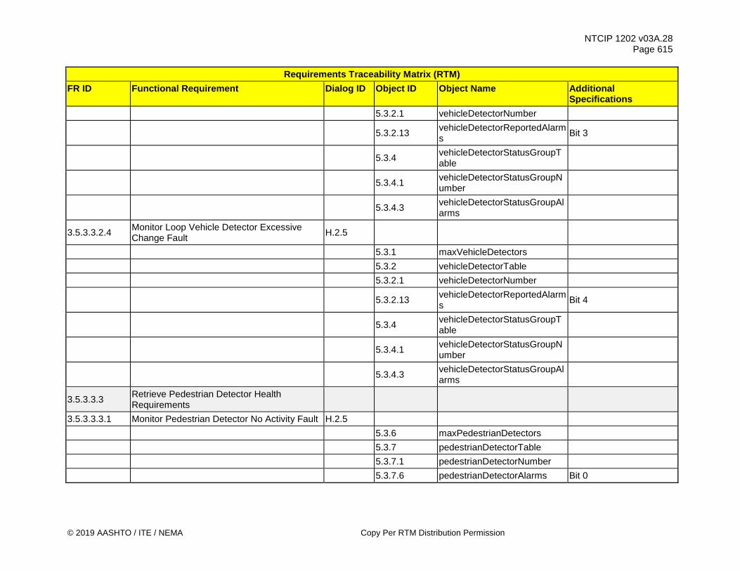
NTCIP 1202 v03A.28 Page 615
© 2019 AASHTO / ITE / NEMA Copy Per RTM Distribution Permission
Requirements Traceability Matrix (RTM) FR ID Functional Requirement Dialog ID Object ID Object Name Additional
Specifications 5.3.2.1 vehicleDetectorNumber
5.3.2.13 vehicleDetectorReportedAlarms Bit 3
5.3.4 vehicleDetectorStatusGroupTable
5.3.4.1 vehicleDetectorStatusGroupNumber
5.3.4.3 vehicleDetectorStatusGroupAlarms
3.5.3.3.2.4 Monitor Loop Vehicle Detector Excessive Change Fault H.2.5
5.3.1 maxVehicleDetectors 5.3.2 vehicleDetectorTable 5.3.2.1 vehicleDetectorNumber
5.3.2.13 vehicleDetectorReportedAlarms Bit 4
5.3.4 vehicleDetectorStatusGroupTable
5.3.4.1 vehicleDetectorStatusGroupNumber
5.3.4.3 vehicleDetectorStatusGroupAlarms
3.5.3.3.3 Retrieve Pedestrian Detector Health Requirements
3.5.3.3.3.1 Monitor Pedestrian Detector No Activity Fault H.2.5 5.3.6 maxPedestrianDetectors 5.3.7 pedestrianDetectorTable 5.3.7.1 pedestrianDetectorNumber 5.3.7.6 pedestrianDetectorAlarms Bit 0

NTCIP 1202 v03A.28 Page 616
Copy Per RTM Distribution Permission © 2019 AASHTO / ITE / NEMA
Requirements Traceability Matrix (RTM) FR ID Functional Requirement Dialog ID Object ID Object Name Additional
Specifications
5.3.9 pedestrianDetectorStatusGroupTable
5.3.9.1 pedestrianDetectorStatusGroupNumber
5.3.9.3 pedestrianDetectorStatusGroupAlarms
3.5.3.3.3.2 Monitor Pedestrian Detector Max Presence Fault H.2.5
5.3.6 maxPedestrianDetectors 5.3.7 pedestrianDetectorTable 5.3.7.1 pedestrianDetectorNumber 5.3.7.6 pedestrianDetectorAlarms Bit 1
5.3.9 pedestrianDetectorStatusGroupTable
5.3.9.1 pedestrianDetectorStatusGroupNumber
5.3.9.3 pedestrianDetectorStatusGroupAlarms
3.5.3.3.3.3 Monitor Pedestrian Detector Erratic Output Fault H.2.5
5.3.6 maxPedestrianDetectors 5.3.7 pedestrianDetectorTable 5.3.7.1 pedestrianDetectorNumber 5.3.7.6 pedestrianDetectorAlarms Bit 2
5.3.9 pedestrianDetectorStatusGroupTable
5.3.9.1 pedestrianDetectorStatusGroupNumber
5.3.9.3 pedestrianDetectorStatusGroupAlarms
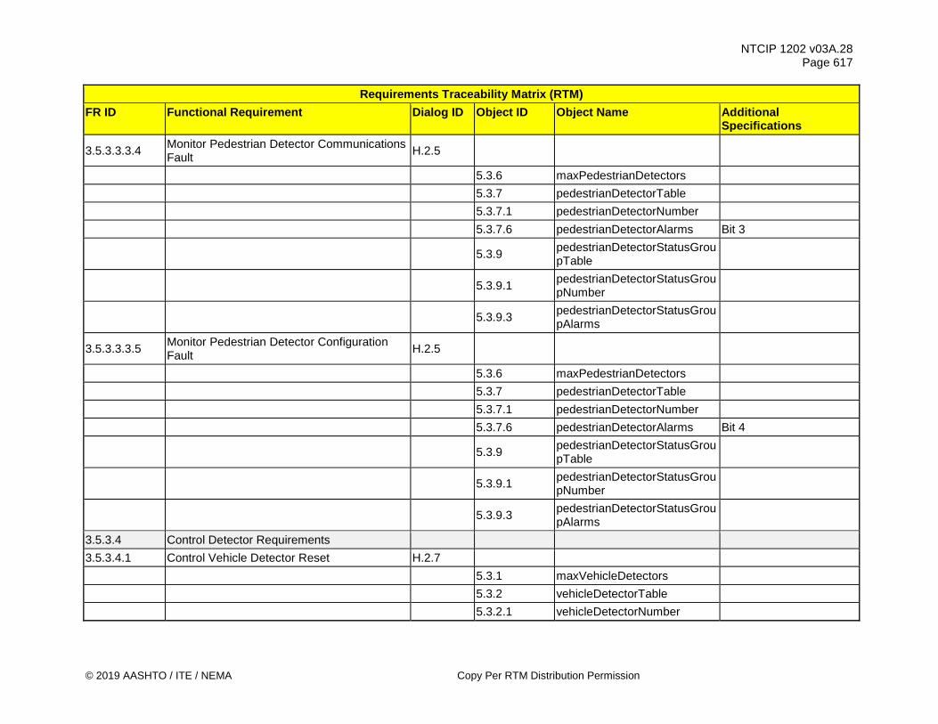
NTCIP 1202 v03A.28 Page 617
© 2019 AASHTO / ITE / NEMA Copy Per RTM Distribution Permission
Requirements Traceability Matrix (RTM) FR ID Functional Requirement Dialog ID Object ID Object Name Additional
Specifications
3.5.3.3.3.4 Monitor Pedestrian Detector Communications Fault H.2.5
5.3.6 maxPedestrianDetectors 5.3.7 pedestrianDetectorTable 5.3.7.1 pedestrianDetectorNumber 5.3.7.6 pedestrianDetectorAlarms Bit 3
5.3.9 pedestrianDetectorStatusGroupTable
5.3.9.1 pedestrianDetectorStatusGroupNumber
5.3.9.3 pedestrianDetectorStatusGroupAlarms
3.5.3.3.3.5 Monitor Pedestrian Detector Configuration Fault H.2.5
5.3.6 maxPedestrianDetectors 5.3.7 pedestrianDetectorTable 5.3.7.1 pedestrianDetectorNumber 5.3.7.6 pedestrianDetectorAlarms Bit 4
5.3.9 pedestrianDetectorStatusGroupTable
5.3.9.1 pedestrianDetectorStatusGroupNumber
5.3.9.3 pedestrianDetectorStatusGroupAlarms
3.5.3.4 Control Detector Requirements 3.5.3.4.1 Control Vehicle Detector Reset H.2.7 5.3.1 maxVehicleDetectors 5.3.2 vehicleDetectorTable 5.3.2.1 vehicleDetectorNumber

NTCIP 1202 v03A.28 Page 618
Copy Per RTM Distribution Permission © 2019 AASHTO / ITE / NEMA
Requirements Traceability Matrix (RTM) FR ID Functional Requirement Dialog ID Object ID Object Name Additional
Specifications 5.3.2.14 vehicleDetectorReset 3.5.3.4.2 Control Pedestrian Detector Reset H.2.7 5.3.6 maxPedestrianDetectors 5.3.7 pedestrianDetectorTable 5.3.7.1 pedestrianDetectorNumber 5.3.7.7 pedestrianDetectorReset 3.5.3.4.3 Control Vehicle Detector Actuation H.2.7
5.3.11 maxVehicleDetectorControlGroups
5.3.11.1 vehicleDetectorControlGroupTable
5.3.11.2 vehicleDetectorControlGroupNumber
5.3.11.3 vehicleDetectorControlGroupActuation
3.5.3.4.4 Control Pedestrian Detector Actuation H.2.7
5.3.8 maxPedestrianDetectorGroups
5.3.12 pedestrianDetectorControlGroupTable
5.3.12.1 pedestrianDetectorControlGroupNumber
5.3.12.2 pedestrianDetectorControlGroupActuation
3.5.3.5 Manage Vehicle Detector Data Collection Requirements
3.5.3.5.1 Configure Vehicle Detector Data Collection Requirements
3.5.3.5.1.1 Configure Detector Data Collection Sample Period Requirements

NTCIP 1202 v03A.28 Page 619
© 2019 AASHTO / ITE / NEMA Copy Per RTM Distribution Permission
Requirements Traceability Matrix (RTM) FR ID Functional Requirement Dialog ID Object ID Object Name Additional
Specifications 3.5.3.5.1.1.1 Configure Detector Data Sample Period G.3 5.3.5.2 volumeOccupancyPeriod
3.5.3.5.1.1.2 Configure Detector Data Sample Period - Version 3 G.3
5.3.5.5 volumeOccupancyPeriodV3
3.5.3.5.2 Retrieve Vehicle Detector Data Collection Requirements
3.5.3.5.2.1 Retrieve Detector Data Collection Sample Period Requirements
3.5.3.5.2.1.1 Monitor Detector Data Sequence G.1 5.3.5.1 volumeOccupancySequence 3.5.3.5.2.1.2 Determine Detector Data Active Detectors G.1
5.3.5.3 activeVolumeOccupancyDetectors
Note: definition slightly changed.
3.5.3.5.2.1.3 Monitor Volume Data H.2.5 5.3.2.1 vehicleDetectorNumber 5.3.5.4 volumeOccupancyTable 5.3.5.4.1 detectorVolume 3.5.3.5.2.1.4 Monitor Average Speed H.2.5 5.3.2.1 vehicleDetectorNumber
5.3.5.3 activeVolumeOccupancyDetectors
5.3.5.4 volumeOccupancyTable 5.3.5.4.3 detectorAvgSpeed 3.5.3.5.2.1.5 Monitor Occupancy Data H.2.5 5.3.2.1 vehicleDetectorNumber
5.3.5.3 activeVolumeOccupancyDetectors
5.3.5.4 volumeOccupancyTable
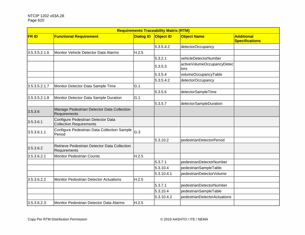
NTCIP 1202 v03A.28 Page 620
Copy Per RTM Distribution Permission © 2019 AASHTO / ITE / NEMA
Requirements Traceability Matrix (RTM) FR ID Functional Requirement Dialog ID Object ID Object Name Additional
Specifications 5.3.5.4.2 detectorOccupancy 3.5.3.5.2.1.6 Monitor Vehicle Detector Data Alarms H.2.5 5.3.2.1 vehicleDetectorNumber
5.3.5.3 activeVolumeOccupancyDetectors
5.3.5.4 volumeOccupancyTable 5.3.5.4.2 detectorOccupancy 3.5.3.5.2.1.7 Monitor Detector Data Sample Time G.1 5.3.5.6 detectorSampleTime 3.5.3.5.2.1.8 Monitor Detector Data Sample Duration G.1 5.3.5.7 detectorSampleDuration
3.5.3.6 Manage Pedestrian Detector Data Collection Requirements
3.5.3.6.1 Configure Pedestrian Detector Data Collection Requirements
3.5.3.6.1.1 Configure Pedestrian Data Collection Sample Period G.3
5.3.10.2 pedestrianDetectorPeriod
3.5.3.6.2 Retrieve Pedestrian Detector Data Collection Requirements
3.5.3.6.2.1 Monitor Pedestrian Counts H.2.5 5.3.7.1 pedestrianDetectorNumber 5.3.10.4 pedestrianSampleTable 5.3.10.4.1 pedestrianDetectorVolume 3.5.3.6.2.2 Monitor Pedestrian Detector Actuations H.2.5 5.3.7.1 pedestrianDetectorNumber 5.3.10.4 pedestrianSampleTable 5.3.10.4.2 pedestrianDetectorActuations 3.5.3.6.2.3 Monitor Pedestrian Detector Data Alarms H.2.5
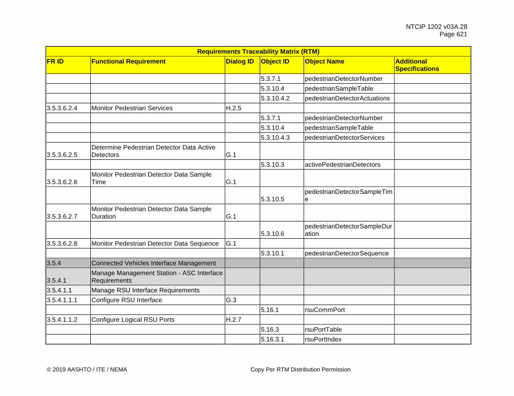
NTCIP 1202 v03A.28 Page 621
© 2019 AASHTO / ITE / NEMA Copy Per RTM Distribution Permission
Requirements Traceability Matrix (RTM) FR ID Functional Requirement Dialog ID Object ID Object Name Additional
Specifications 5.3.7.1 pedestrianDetectorNumber 5.3.10.4 pedestrianSampleTable 5.3.10.4.2 pedestrianDetectorActuations 3.5.3.6.2.4 Monitor Pedestrian Services H.2.5 5.3.7.1 pedestrianDetectorNumber 5.3.10.4 pedestrianSampleTable 5.3.10.4.3 pedestrianDetectorServices
3.5.3.6.2.5 Determine Pedestrian Detector Data Active Detectors G.1
5.3.10.3 activePedestrianDetectors
3.5.3.6.2.6 Monitor Pedestrian Detector Data Sample Time G.1
5.3.10.5 pedestrianDetectorSampleTime
3.5.3.6.2.7 Monitor Pedestrian Detector Data Sample Duration G.1
5.3.10.6 pedestrianDetectorSampleDuration
3.5.3.6.2.8 Monitor Pedestrian Detector Data Sequence G.1 5.3.10.1 pedestrianDetectorSequence 3.5.4 Connected Vehicles Interface Management
3.5.4.1 Manage Management Station - ASC Interface Requirements
3.5.4.1.1 Manage RSU Interface Requirements 3.5.4.1.1.1 Configure RSU Interface G.3 5.16.1 rsuCommPort 3.5.4.1.1.2 Configure Logical RSU Ports H.2.7 5.16.3 rsuPortTable 5.16.3.1 rsuPortIndex
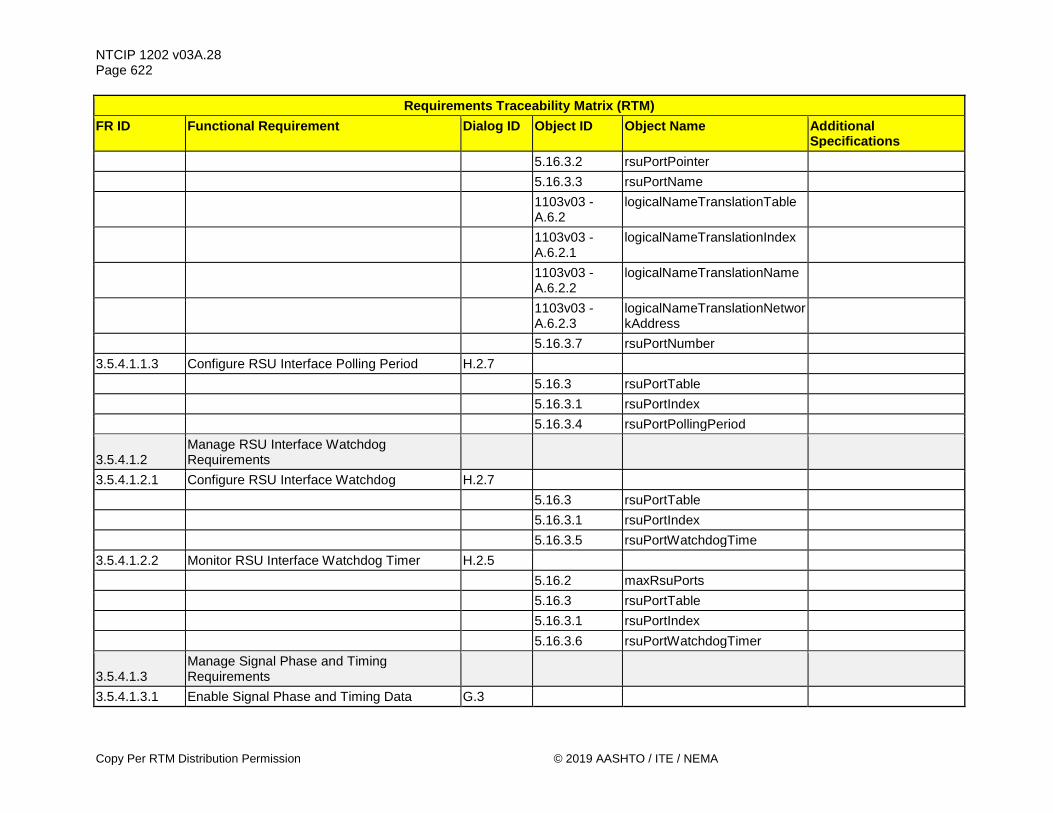
NTCIP 1202 v03A.28 Page 622
Copy Per RTM Distribution Permission © 2019 AASHTO / ITE / NEMA
Requirements Traceability Matrix (RTM) FR ID Functional Requirement Dialog ID Object ID Object Name Additional
Specifications 5.16.3.2 rsuPortPointer 5.16.3.3 rsuPortName
1103v03 - A.6.2
logicalNameTranslationTable
1103v03 - A.6.2.1
logicalNameTranslationIndex
1103v03 - A.6.2.2
logicalNameTranslationName
1103v03 - A.6.2.3
logicalNameTranslationNetworkAddress
5.16.3.7 rsuPortNumber 3.5.4.1.1.3 Configure RSU Interface Polling Period H.2.7 5.16.3 rsuPortTable 5.16.3.1 rsuPortIndex 5.16.3.4 rsuPortPollingPeriod
3.5.4.1.2 Manage RSU Interface Watchdog Requirements
3.5.4.1.2.1 Configure RSU Interface Watchdog H.2.7 5.16.3 rsuPortTable 5.16.3.1 rsuPortIndex 5.16.3.5 rsuPortWatchdogTime 3.5.4.1.2.2 Monitor RSU Interface Watchdog Timer H.2.5 5.16.2 maxRsuPorts 5.16.3 rsuPortTable 5.16.3.1 rsuPortIndex 5.16.3.6 rsuPortWatchdogTimer
3.5.4.1.3 Manage Signal Phase and Timing Requirements
3.5.4.1.3.1 Enable Signal Phase and Timing Data G.3

NTCIP 1202 v03A.28 Page 623
© 2019 AASHTO / ITE / NEMA Copy Per RTM Distribution Permission
Requirements Traceability Matrix (RTM) FR ID Functional Requirement Dialog ID Object ID Object Name Additional
Specifications 5.17.4 spatOptions 3.5.4.1.3.2 Retrieve Intersection Identifier H.2.5
1217v01 - 1.3.6
mapIntersectionTable See 7.3.6.
1217v01 - 1.3.6.1
mapIntersectionIndex See 7.3.6.1.
1217v01 - 1.3.6.2
mapIntersectionId See 7.3.6.2.
1217v01 - 1.3.6.4
mapIntersectionAuthority See 7.3.6.4.
3.5.4.1.3.3 Retrieve Signal Phase and Timing Time Point G.1 5.17.6 ascCurrentTick
3.5.4.1.3.4 Retrieve Signal Phase and Timing Generation Time G.1
5.17.1 spatTimestamp
3.5.4.1.3.5 Retrieve Signal Phase and Timing Intersection Status G.1
1217v01 - 1.2.1
spatStatus See 7.2.1.
3.5.4.1.3.6 Exchange Movement Status Requirements 3.5.4.1.3.6.1 Monitor Movement State H.2.5 5.9.1 maxChannels 5.9.2.1 channelNumber
1217v01 - 1.2.7
signalStatusTable See 7.2.7.
1217v01 - 1.2.7.1
signalState See 7.2.7.1
3.5.4.1.3.6.2 Retrieve Movement Timing Requirements 3.5.4.1.3.6.2.1 Monitor Movement Minimum End Time H.2.5 5.9.1 maxChannels

NTCIP 1202 v03A.28 Page 624
Copy Per RTM Distribution Permission © 2019 AASHTO / ITE / NEMA
Requirements Traceability Matrix (RTM) FR ID Functional Requirement Dialog ID Object ID Object Name Additional
Specifications 5.9.2.1 channelNumber
1217v01 - 1.2.7
signalStatusTable See 7.2.7.
1217v01 - 1.2.7.2
signalStateMinEndTick See 7.2.7.2.
3.5.4.1.3.6.2.2 Monitor Movement Maximum End Time H.2.5 5.9.1 maxChannels 5.9.2.1 channelNumber
1217v01 - 1.2.7
signalStatusTable See 7.2.7.
1217v01 - 1.2.7.3
signalStateMaxEndTick See 7.2.7.3.
3.5.4.1.3.6.2.3 Monitor Movement Likely End Time H.2.5 5.9.1 maxChannels 5.9.2.1 channelNumber
1217v01 - 1.2.7
signalStatusTable See 7.2.7.
1217v01 - 1.2.7.4
signalStateLikelyEndTick See 7.2.7.4.
3.5.4.1.3.6.2.4 Monitor Movement Likely End Time Confidence H.2.5
5.9.1 maxChannels 5.9.2.1 channelNumber
1217v01 - 1.2.7
signalStatusTable See 7.2.7.
1217v01 - 1.2.7.5
signalStateTickConfidence See 7.2.7.5.
3.5.4.1.3.6.2.5 Monitor Movement Next Occurrence H.2.5 5.9.1 maxChannels 5.9.2.1 channelNumber

NTCIP 1202 v03A.28 Page 625
© 2019 AASHTO / ITE / NEMA Copy Per RTM Distribution Permission
Requirements Traceability Matrix (RTM) FR ID Functional Requirement Dialog ID Object ID Object Name Additional
Specifications
1217v01 - 1.2.7
signalStatusTable See 7.2.7.
1217v01 - 1.2.7.6
signalNextTick See 7.2.7.6.
3.5.4.1.3.6.3 Configure Movement Assistance Requirements
3.5.4.1.3.6.3.1 Configure Queue Detectors for Movement Assistance H.2.7
5.9.2.1 channelNumber
1217v01 - 1.2.5
movementManeuverTable See 7.2.5.
1217v01 - 1.2.5.1
movementManeuverIndex See 7.2.5.1.
1217v01 - 1.2.5.7
movementManeuverQueueDetector See 7.2.5.7.
3.5.4.1.3.6.3.2 Configure Pedestrian Detectors for Movement Assistance H.2.7
5.9.2.1 channelNumber
1217v01 - 1.2.5
movementManeuverTable See 7.2.5.
1217v01 - 1.2.5.1
movementManeuverIndex See 7.2.5.1.
1217v01 - 1.2.5.8
movementManeuverPedPresence See 7.2.5.8.
3.5.4.1.3.6.3.3 Configure Bicycle Detectors for Movement Assistance H.2.7
5.9.2.1 channelNumber
1217v01 - 1.2.5
movementManeuverTable See 7.2.5.
1217v01 - 1.2.5.1
movementManeuverIndex See 7.2.5.1.
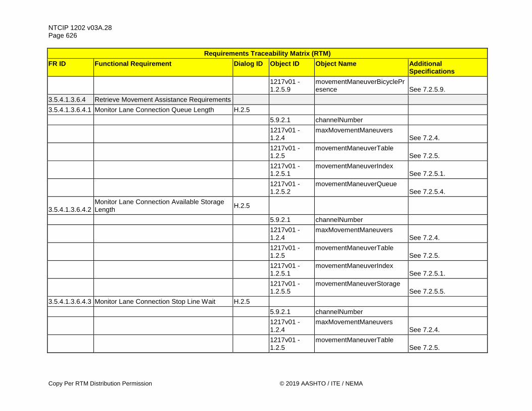
NTCIP 1202 v03A.28 Page 626
Copy Per RTM Distribution Permission © 2019 AASHTO / ITE / NEMA
Requirements Traceability Matrix (RTM) FR ID Functional Requirement Dialog ID Object ID Object Name Additional
Specifications
1217v01 - 1.2.5.9
movementManeuverBicyclePresence See 7.2.5.9.
3.5.4.1.3.6.4 Retrieve Movement Assistance Requirements 3.5.4.1.3.6.4.1 Monitor Lane Connection Queue Length H.2.5 5.9.2.1 channelNumber
1217v01 - 1.2.4
maxMovementManeuvers See 7.2.4.
1217v01 - 1.2.5
movementManeuverTable See 7.2.5.
1217v01 - 1.2.5.1
movementManeuverIndex See 7.2.5.1.
1217v01 - 1.2.5.2
movementManeuverQueue See 7.2.5.4.
3.5.4.1.3.6.4.2 Monitor Lane Connection Available Storage Length H.2.5
5.9.2.1 channelNumber
1217v01 - 1.2.4
maxMovementManeuvers See 7.2.4.
1217v01 - 1.2.5
movementManeuverTable See 7.2.5.
1217v01 - 1.2.5.1
movementManeuverIndex See 7.2.5.1.
1217v01 - 1.2.5.5
movementManeuverStorage See 7.2.5.5.
3.5.4.1.3.6.4.3 Monitor Lane Connection Stop Line Wait H.2.5 5.9.2.1 channelNumber
1217v01 - 1.2.4
maxMovementManeuvers See 7.2.4.
1217v01 - 1.2.5
movementManeuverTable See 7.2.5.

NTCIP 1202 v03A.28 Page 627
© 2019 AASHTO / ITE / NEMA Copy Per RTM Distribution Permission
Requirements Traceability Matrix (RTM) FR ID Functional Requirement Dialog ID Object ID Object Name Additional
Specifications
1217v01 - 1.2.5.1
movementManeuverIndex See 7.2.5.1.
1217v01 - 1.2.5.6
movementManeuverStatus See 7.2.5.6.
3.5.4.1.3.6.4.4 Monitor Lane Connection Traveler Detection H.2.5
5.9.2.1 channelNumber
1217v01 - 1.2.4
maxMovementManeuvers See 7.2.4.
1217v01 - 1.2.5
movementManeuverTable See 7.2.5.
1217v01 - 1.2.5.1
movementManeuverIndex See 7.2.5.1.
1217v01 - 1.2.5.6
movementManeuverStatus See 7.2.5.6.
3.5.4.1.3.6.4.5 Monitor Lane Connection State H.2.5 5.9.2.1 channelNumber
1217v01 - 1.2.4
maxMovementManeuvers See 7.2.4.
1217v01 - 1.2.5
movementManeuverTable See 7.2.5.
1217v01 - 1.2.5.1
movementManeuverIndex See 7.2.5.1.
1217v01 - 1.2.5.3
movementManeuverState See 7.2.5.3.
3.5.4.1.3.6.5 Manage Advisory Speed Requirements 3.5.4.1.3.6.5.1 Configure Advisory Speed Type H.2.7 5.9.2 channelTable 5.9.2.1 channelNumber
1217v01 - 1.2.3
advisorySpeedTable See 7.2.3.

NTCIP 1202 v03A.28 Page 628
Copy Per RTM Distribution Permission © 2019 AASHTO / ITE / NEMA
Requirements Traceability Matrix (RTM) FR ID Functional Requirement Dialog ID Object ID Object Name Additional
Specifications
1217v01 - 1.2.3.1
advisorySpeedIndex See 7.2.3.1.
1217v01 - 1.2.3.2
advisorySpeedType See 7.2.3.2.
3.5.4.1.3.6.5.2 Configure Advisory Speed H.2.7 5.9.2 channelTable 5.9.2.1 channelNumber
1217v01 - 1.2.3
advisorySpeedTable See 7.2.3.
1217v01 - 1.2.3.1
advisorySpeedIndex See 7.2.3.1.
1217v01 - 1.2.3.3
advisorySpeedAdvice See 7.2.3.3.
3.5.4.1.3.6.5.3 Configure Advisory Speed Zone H.2.7 5.9.2 channelTable 5.9.2.1 channelNumber
1217v01 - 1.2.3
advisorySpeedTable See 7.2.3.
1217v01 - 1.2.3.1
advisorySpeedIndex See 7.2.3.1.
1217v01 - 1.2.3.4
advisorySpeedZoneLength See 7.2.3.4.
3.5.4.1.3.6.5.4 Configure Advisory Speed Vehicle Type H.2.7 5.9.2 channelTable 5.9.2.1 channelNumber
1217v01 - 1.2.3
advisorySpeedTable See 7.2.3.
1217v01 - 1.2.3.1
advisorySpeedIndex See 7.2.3.1.
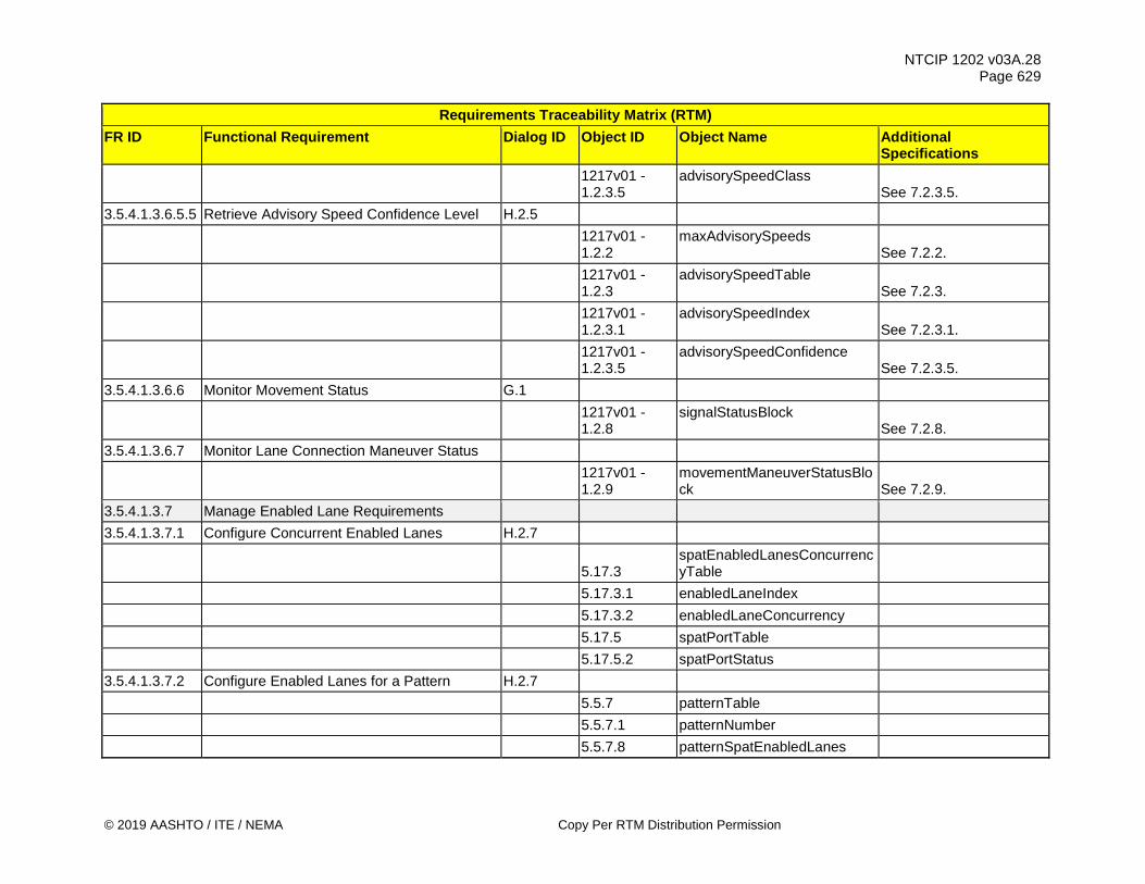
NTCIP 1202 v03A.28 Page 629
© 2019 AASHTO / ITE / NEMA Copy Per RTM Distribution Permission
Requirements Traceability Matrix (RTM) FR ID Functional Requirement Dialog ID Object ID Object Name Additional
Specifications
1217v01 - 1.2.3.5
advisorySpeedClass See 7.2.3.5.
3.5.4.1.3.6.5.5 Retrieve Advisory Speed Confidence Level H.2.5
1217v01 - 1.2.2
maxAdvisorySpeeds See 7.2.2.
1217v01 - 1.2.3
advisorySpeedTable See 7.2.3.
1217v01 - 1.2.3.1
advisorySpeedIndex See 7.2.3.1.
1217v01 - 1.2.3.5
advisorySpeedConfidence See 7.2.3.5.
3.5.4.1.3.6.6 Monitor Movement Status G.1
1217v01 - 1.2.8
signalStatusBlock See 7.2.8.
3.5.4.1.3.6.7 Monitor Lane Connection Maneuver Status
1217v01 - 1.2.9
movementManeuverStatusBlock See 7.2.9.
3.5.4.1.3.7 Manage Enabled Lane Requirements 3.5.4.1.3.7.1 Configure Concurrent Enabled Lanes H.2.7
5.17.3 spatEnabledLanesConcurrencyTable
5.17.3.1 enabledLaneIndex 5.17.3.2 enabledLaneConcurrency 5.17.5 spatPortTable 5.17.5.2 spatPortStatus 3.5.4.1.3.7.2 Configure Enabled Lanes for a Pattern H.2.7 5.5.7 patternTable 5.5.7.1 patternNumber 5.5.7.8 patternSpatEnabledLanes

NTCIP 1202 v03A.28 Page 630
Copy Per RTM Distribution Permission © 2019 AASHTO / ITE / NEMA
Requirements Traceability Matrix (RTM) FR ID Functional Requirement Dialog ID Object ID Object Name Additional
Specifications 3.5.4.1.3.7.3 Command Enabled Lanes 4.2.9 5.16.3 rsuPortTable 5.16.3.1 rsuPortIndex 5.17.2 spatEnabledLanesCommand 5.17.5 spatPortTable 5.17.5.2 spatPortStatus 3.5.4.1.3.8 Configure Movement Type H.2.7 5.9.2 channelTable 5.9.2.1 channelNumber 5.9.2.6 channelGreenType 5.9.2.7 channelGreenIncluded 3.5.4.1.3.9 Configure Lane Connection Type H.2.7 5.9.2 channelTable 5.9.2.1 channelNumber
1217v01 - 1.2.5
movementManeuverTable See 7.2.5.
1217v01 - 1.2.5.1
movementManeuverIndex See 7.2.5.1.
1217v01 - 1.2.5.2
movementManeuverId See 7.2.5.2.
1217v01 - 1.2.5.10
movementManeuverGreenType See 7.2.5.10.
1217v01 - 1.2.5.11
movementManeuverGreenIncluded See 7.2.5.11.
3.5.4.1.3.10 Enable Signal Phase and Timing Data Exchange H.2.7
5.16.3 rsuPortTable 5.16.3.1 rsuPortIndex 5.17.5 spatPortTable

NTCIP 1202 v03A.28 Page 631
© 2019 AASHTO / ITE / NEMA Copy Per RTM Distribution Permission
Requirements Traceability Matrix (RTM) FR ID Functional Requirement Dialog ID Object ID Object Name Additional
Specifications 5.17.5.1 spatPortOptions
3.5.4.2 Manage Management Station - CV Roadside Process Interface Requirements
3.5.4.2.1 Manage Roadway Geometrics Information Requirements
3.5.4.2.1.1 Configure Roadway Geometry Plans Requirements
3.5.4.2.1.1.1 Configure Intersection Identifier H.2.7
1217v01 - 1.3.6
mapIntersectionTable See 7.3.6.
1217v01 - 1.3.6.1
mapIntersectionIndex See 7.3.6.1.
1217v01 - 1.3.6.2
mapIntersectionId See 7.3.6.2.
1217v01 - 1.3.6.4
mapIntersectionAuthority See 7.3.6.4.
3.5.4.2.1.1.2 Configure Intersection Location H.2.7
1217v01 - 1.3.6
mapIntersectionTable See 7.3.6.
1217v01 - 1.3.6.1
mapIntersectionIndex See 7.3.6.1.
1217v01 - 1.3.6.5
mapIntersectionLatitude See 7.3.6.5.
1217v01 - 1.3.6.6
mapIntersectionLongitude See 7.3.6.6.
1217v01 - 1.3.6.7
mapIntersectionElevation See 7.3.6.7.
3.5.4.2.1.1.3 Configure Intersection Name H.2.7
1217v01 - 1.3.6
mapIntersectionTable See 7.3.6.

NTCIP 1202 v03A.28 Page 632
Copy Per RTM Distribution Permission © 2019 AASHTO / ITE / NEMA
Requirements Traceability Matrix (RTM) FR ID Functional Requirement Dialog ID Object ID Object Name Additional
Specifications
1217v01 - 1.3.6.1
mapIntersectionIndex See 7.3.6.1.
1217v01 - 1.3.6.3
mapIntersectionName See 7.3.6.3.
3.5.4.2.1.1.4 Configure Intersection Default Lane Width H.2.7
1217v01 - 1.3.6
mapIntersectionTable See 7.3.6.
1217v01 - 1.3.6.1
mapIntersectionIndex See 7.3.6.1.
1217v01 - 1.3.6.8
mapIntersectionDefaultWidth See 7.3.6.8.
3.5.4.2.1.1.5 Manage Lane Requirements 3.5.4.2.1.1.5.1 Configure Lane Identifier H.2.7
1217v01 - 1.3.4
mapLaneTable See 7.3.4.
1217v01 - 1.3.4.1
mapLaneIndex See 7.3.4.1.
1217v01 - 1.3.4.2
mapLaneIntersection See 7.3.4.2.
1217v01 - 1.3.4.3
mapLaneNumber See 7.3.4.3.
1217v01 - 1.3.4.13
mapLaneCRC See 7.3.4.13.
3.5.4.2.1.1.5.2 Configure Lane Description H.2.7
1217v01 - 1.3.4
mapLaneTable See 7.3.4.
1217v01 - 1.3.4.1
mapLaneIndex See 7.3.4.1.
1217v01 - 1.3.4.4
mapLaneName See 7.3.4.4.
3.5.4.2.1.1.5.3 Configure Ingress Approach H.2.7

NTCIP 1202 v03A.28 Page 633
© 2019 AASHTO / ITE / NEMA Copy Per RTM Distribution Permission
Requirements Traceability Matrix (RTM) FR ID Functional Requirement Dialog ID Object ID Object Name Additional
Specifications
1217v01 - 1.3.4
mapLaneTable See 7.3.4.
1217v01 - 1.3.4.1
mapLaneIndex See 7.3.4.1.
1217v01 - 1.3.4.11
mapLaneIngress See 7.3.4.11.
3.5.4.2.1.1.5.4 Configure Egress Approach H.2.7
1217v01 - 1.3.4
mapLaneTable See 7.3.4.
1217v01 - 1.3.4.1
mapLaneIndex See 7.3.4.1.
1217v01 - 1.3.4.12
mapLaneEgress See 7.3.4.12.
3.5.4.2.1.1.5.5 Configure Allowed Lane Direction H.2.7
1217v01 - 1.3.4
mapLaneTable See 7.3.4.
1217v01 - 1.3.4.1
mapLaneIndex See 7.3.4.1.
1217v01 - 1.3.4.5
mapLaneDirection See 7.3.4.5.
1217v01 - 1.3.4.13
mapLaneCRC See 7.3.4.13.
3.5.4.2.1.1.5.6 Configure Vehicle Lane Attributes H.2.7
1217v01 - 1.3.4
mapLaneTable See 7.3.4.
1217v01 - 1.3.4.1
mapLaneIndex See 7.3.4.1.
1217v01 - 1.3.4.7
mapLaneType See 7.3.4.7.
1217v01 - 1.3.4.8
mapLaneAttribute See 7.3.4.8.

NTCIP 1202 v03A.28 Page 634
Copy Per RTM Distribution Permission © 2019 AASHTO / ITE / NEMA
Requirements Traceability Matrix (RTM) FR ID Functional Requirement Dialog ID Object ID Object Name Additional
Specifications
1217v01 - 1.3.4.13
mapLaneCRC See 7.3.4.13.
3.5.4.2.1.1.5.7 Configure Crosswalk Attributes H.2.7
1217v01 - 1.3.4
mapLaneTable See 7.3.4.
1217v01 - 1.3.4.1
mapLaneIndex See 7.3.4.1.
1217v01 - 1.3.4.7
mapLaneType See 7.3.4.7.
1217v01 - 1.3.4.8
mapLaneAttribute See 7.3.4.8.
1217v01 - 1.3.4.13
mapLaneCRC See 7.3.4.13.
3.5.4.2.1.1.5.8 Configure Bicycle Lane Attributes H.2.7
1217v01 - 1.3.4
mapLaneTable See 7.3.4.
1217v01 - 1.3.4.1
mapLaneIndex See 7.3.4.1.
1217v01 - 1.3.4.7
mapLaneType See 7.3.4.7.
1217v01 - 1.3.4.8
mapLaneAttribute See 7.3.4.8.
1217v01 - 1.3.4.13
mapLaneCRC See 7.3.4.13.
3.5.4.2.1.1.5.9 Configure Sidewalk Attributes H.2.7
1217v01 - 1.3.4
mapLaneTable See 7.3.4.
1217v01 - 1.3.4.1
mapLaneIndex See 7.3.4.1.
1217v01 - 1.3.4.7
mapLaneType See 7.3.4.7.

NTCIP 1202 v03A.28 Page 635
© 2019 AASHTO / ITE / NEMA Copy Per RTM Distribution Permission
Requirements Traceability Matrix (RTM) FR ID Functional Requirement Dialog ID Object ID Object Name Additional
Specifications
1217v01 - 1.3.4.8
mapLaneAttribute See 7.3.4.8.
1217v01 - 1.3.4.13
mapLaneCRC See 7.3.4.13.
3.5.4.2.1.1.5.10 Configure Barrier Attributes H.2.7
1217v01 - 1.3.4
mapLaneTable See 7.3.4.
1217v01 - 1.3.4.1
mapLaneIndex See 7.3.4.1.
1217v01 - 1.3.4.7
mapLaneType See 7.3.4.7.
1217v01 - 1.3.4.8
mapLaneAttribute See 7.3.4.8.
1217v01 - 1.3.4.13
mapLaneCRC See 7.3.4.13.
3.5.4.2.1.1.5.11 Configure Striping Lane Attributes H.2.7
1217v01 - 1.3.4
mapLaneTable See 7.3.4.
1217v01 - 1.3.4.1
mapLaneIndex See 7.3.4.1.
1217v01 - 1.3.4.7
mapLaneType See 7.3.4.7.
1217v01 - 1.3.4.8
mapLaneAttribute See 7.3.4.8.
1217v01 - 1.3.4.13
mapLaneCRC See 7.3.4.13.
3.5.4.2.1.1.5.12 Configure Tracked Lane Attributes H.2.7

NTCIP 1202 v03A.28 Page 636
Copy Per RTM Distribution Permission © 2019 AASHTO / ITE / NEMA
Requirements Traceability Matrix (RTM) FR ID Functional Requirement Dialog ID Object ID Object Name Additional
Specifications
1217v01 - 1.3.4
mapLaneTable See 7.3.4.
1217v01 - 1.3.4.1
mapLaneIndex See 7.3.4.1.
1217v01 - 1.3.4.7
mapLaneType See 7.3.4.7.
1217v01 - 1.3.4.8
mapLaneAttribute See 7.3.4.8.
1217v01 - 1.3.4.13
mapLaneCRC See 7.3.4.13.
3.5.4.2.1.1.5.13 Configure Parked Lane Attributes H.2.7
1217v01 - 1.3.4
mapLaneTable See 7.3.4.
1217v01 - 1.3.4.1
mapLaneIndex See 7.3.4.1.
1217v01 - 1.3.4.7
mapLaneType See 7.3.4.7.
1217v01 - 1.3.4.8
mapLaneAttribute See 7.3.4.8.
1217v01 - 1.3.4.13
mapLaneCRC See 7.3.4.13.
3.5.4.2.1.1.5.14 Configure Shared Lanes Attributes H.2.7
1217v01 - 1.3.4
mapLaneTable See 7.3.4.
1217v01 - 1.3.4.1
mapLaneIndex See 7.3.4.1.
1217v01 - 1.3.4.6
mapLaneSharing See 7.3.4.6.

NTCIP 1202 v03A.28 Page 637
© 2019 AASHTO / ITE / NEMA Copy Per RTM Distribution Permission
Requirements Traceability Matrix (RTM) FR ID Functional Requirement Dialog ID Object ID Object Name Additional
Specifications
1217v01 - 1.3.4.13
mapLaneCRC See 7.3.4.13.
3.5.4.2.1.1.5.15 Configure Allowed Maneuvers H.2.7
1217v01 - 1.3.4
mapLaneTable See 7.3.4.
1217v01 - 1.3.4.1
mapLaneIndex See 7.3.4.1.
1217v01 - 1.3.4.9
mapLaneManeuver See 7.3.4.9.
1217v01 - 1.3.4.13
mapLaneCRC See 7.3.4.13.
3.5.4.2.1.1.5.16 Configure Lane Path 4.2.4
1217v01 - 1.3.4.1
mapLaneIndex See 7.3.4.1.
1217v01 - 1.3.4.13
mapLaneCRC See 7.3.4.13.
1217v01 - 1.3.8
mapNodePointTable See 7.3.8.
1217v01 - 1.3.8.1
mapNodePointNumber See 7.3.8.1.
1217v01 - 1.3.8.2
mapNodePointX See 7.3.8.2.
1217v01 - 1.3.8.3
mapNodePointY See 7.3.8.3.
1217v01 - 1.3.8.4
mapNodePointAttribute See 7.3.8.4.
3.5.4.2.1.1.6 Configure Node Point Requirements 3.5.4.2.1.1.6.1 Configure Node Point Attributes H.2.7
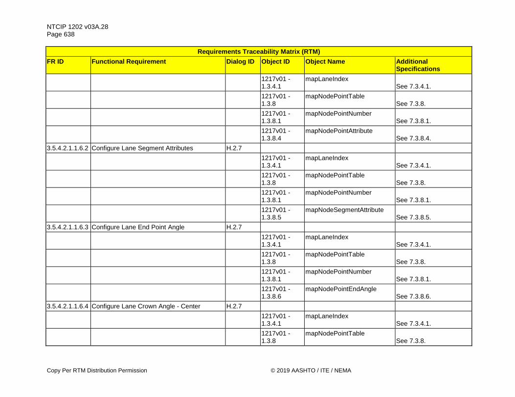
NTCIP 1202 v03A.28 Page 638
Copy Per RTM Distribution Permission © 2019 AASHTO / ITE / NEMA
Requirements Traceability Matrix (RTM) FR ID Functional Requirement Dialog ID Object ID Object Name Additional
Specifications
1217v01 - 1.3.4.1
mapLaneIndex See 7.3.4.1.
1217v01 - 1.3.8
mapNodePointTable See 7.3.8.
1217v01 - 1.3.8.1
mapNodePointNumber See 7.3.8.1.
1217v01 - 1.3.8.4
mapNodePointAttribute See 7.3.8.4.
3.5.4.2.1.1.6.2 Configure Lane Segment Attributes H.2.7
1217v01 - 1.3.4.1
mapLaneIndex See 7.3.4.1.
1217v01 - 1.3.8
mapNodePointTable See 7.3.8.
1217v01 - 1.3.8.1
mapNodePointNumber See 7.3.8.1.
1217v01 - 1.3.8.5
mapNodeSegmentAttribute See 7.3.8.5.
3.5.4.2.1.1.6.3 Configure Lane End Point Angle H.2.7
1217v01 - 1.3.4.1
mapLaneIndex See 7.3.4.1.
1217v01 - 1.3.8
mapNodePointTable See 7.3.8.
1217v01 - 1.3.8.1
mapNodePointNumber See 7.3.8.1.
1217v01 - 1.3.8.6
mapNodePointEndAngle See 7.3.8.6.
3.5.4.2.1.1.6.4 Configure Lane Crown Angle - Center H.2.7
1217v01 - 1.3.4.1
mapLaneIndex See 7.3.4.1.
1217v01 - 1.3.8
mapNodePointTable See 7.3.8.
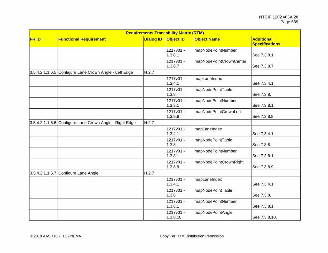
NTCIP 1202 v03A.28 Page 639
© 2019 AASHTO / ITE / NEMA Copy Per RTM Distribution Permission
Requirements Traceability Matrix (RTM) FR ID Functional Requirement Dialog ID Object ID Object Name Additional
Specifications
1217v01 - 1.3.8.1
mapNodePointNumber See 7.3.8.1.
1217v01 - 1.3.8.7
mapNodePointCrownCenter See 7.3.8.7.
3.5.4.2.1.1.6.5 Configure Lane Crown Angle - Left Edge H.2.7
1217v01 - 1.3.4.1
mapLaneIndex See 7.3.4.1.
1217v01 - 1.3.8
mapNodePointTable See 7.3.8.
1217v01 - 1.3.8.1
mapNodePointNumber See 7.3.8.1.
1217v01 - 1.3.8.8
mapNodePointCrownLeft See 7.3.8.8.
3.5.4.2.1.1.6.6 Configure Lane Crown Angle - Right Edge H.2.7
1217v01 - 1.3.4.1
mapLaneIndex See 7.3.4.1.
1217v01 - 1.3.8
mapNodePointTable See 7.3.8.
1217v01 - 1.3.8.1
mapNodePointNumber See 7.3.8.1.
1217v01 - 1.3.8.9
mapNodePointCrownRight See 7.3.8.9.
3.5.4.2.1.1.6.7 Configure Lane Angle H.2.7
1217v01 - 1.3.4.1
mapLaneIndex See 7.3.4.1.
1217v01 - 1.3.8
mapNodePointTable See 7.3.8.
1217v01 - 1.3.8.1
mapNodePointNumber See 7.3.8.1.
1217v01 - 1.3.8.10
mapNodePointAngle See 7.3.8.10.

NTCIP 1202 v03A.28 Page 640
Copy Per RTM Distribution Permission © 2019 AASHTO / ITE / NEMA
Requirements Traceability Matrix (RTM) FR ID Functional Requirement Dialog ID Object ID Object Name Additional
Specifications 3.5.4.2.1.1.6.8 Configure Speed Limit Type at Node 4.2.6
1217v01 - 1.3.4.1
mapLaneIndex See 7.3.4.1.
1217v01 - 1.3.8
mapNodePointTable See 7.3.8.
1217v01 - 1.3.8.1
mapNodePointNumber See 7.3.8.1.
1217v01 - 1.3.8.13
mapNodePointSpeedLimits See 7.3.8.13.
1217v01 - 1.3.14
mapSpeedLimitTable See 7.3.14.
1217v01 - 1.3.14.1
mapSpeedLimitIndex See 7.3.14.1.
1217v01 - 1.3.14.2
mapSpeedLimitType See 7.3.14.2.
1217v01 - 1.3.14.3
mapSpeedLimit See 7.3.14.3.
3.5.4.2.1.1.6.9 Configure Speed Limit at Node 4.2.6
1217v01 - 1.3.4.1
mapLaneIndex See 7.3.4.1.
1217v01 - 1.3.8
mapNodePointTable See 7.3.8.
1217v01 - 1.3.8.1
mapNodePointNumber See 7.3.8.1.
1217v01 - 1.3.8.13
mapNodePointSpeedLimits See 7.3.8.13.
1217v01 - 1.3.14
mapSpeedLimitTable See 7.3.14.
1217v01 - 1.3.14.1
mapSpeedLimitIndex See 7.3.14.1.
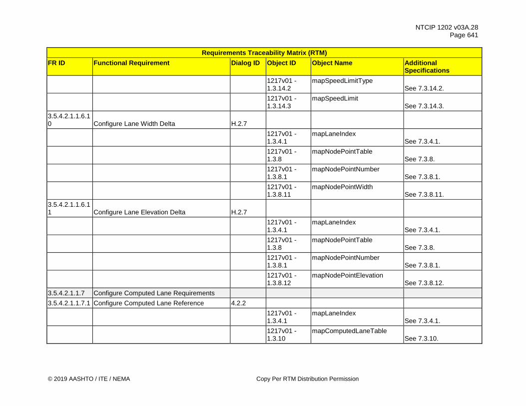
NTCIP 1202 v03A.28 Page 641
© 2019 AASHTO / ITE / NEMA Copy Per RTM Distribution Permission
Requirements Traceability Matrix (RTM) FR ID Functional Requirement Dialog ID Object ID Object Name Additional
Specifications
1217v01 - 1.3.14.2
mapSpeedLimitType See 7.3.14.2.
1217v01 - 1.3.14.3
mapSpeedLimit See 7.3.14.3.
3.5.4.2.1.1.6.10 Configure Lane Width Delta H.2.7
1217v01 - 1.3.4.1
mapLaneIndex See 7.3.4.1.
1217v01 - 1.3.8
mapNodePointTable See 7.3.8.
1217v01 - 1.3.8.1
mapNodePointNumber See 7.3.8.1.
1217v01 - 1.3.8.11
mapNodePointWidth See 7.3.8.11.
3.5.4.2.1.1.6.11 Configure Lane Elevation Delta H.2.7
1217v01 - 1.3.4.1
mapLaneIndex See 7.3.4.1.
1217v01 - 1.3.8
mapNodePointTable See 7.3.8.
1217v01 - 1.3.8.1
mapNodePointNumber See 7.3.8.1.
1217v01 - 1.3.8.12
mapNodePointElevation See 7.3.8.12.
3.5.4.2.1.1.7 Configure Computed Lane Requirements 3.5.4.2.1.1.7.1 Configure Computed Lane Reference 4.2.2
1217v01 - 1.3.4.1
mapLaneIndex See 7.3.4.1.
1217v01 - 1.3.10
mapComputedLaneTable See 7.3.10.

NTCIP 1202 v03A.28 Page 642
Copy Per RTM Distribution Permission © 2019 AASHTO / ITE / NEMA
Requirements Traceability Matrix (RTM) FR ID Functional Requirement Dialog ID Object ID Object Name Additional
Specifications
1217v01 - 1.3.10.1
mapComputedLaneReference See 7.3.10.1.
3.5.4.2.1.1.7.2 Configure Computed Lane X Offset 4.2.2
1217v01 - 1.3.4.1
mapLaneIndex See 7.3.4.1.
1217v01 - 1.3.10
mapComputedLaneTable See 7.3.10.
1217v01 - 1.3.10.2
mapComputedLaneXOffset See 7.3.10.2.
3.5.4.2.1.1.7.3 Configure Computed Lane Y Offset 4.2.2
1217v01 - 1.3.4.1
mapLaneIndex See 7.3.4.1.
1217v01 - 1.3.10
mapComputedLaneTable See 7.3.10.
1217v01 - 1.3.10.3
mapComputedLaneYOffset See 7.3.10.3.
3.5.4.2.1.1.7.4 Configure Computed Lane Rotation 4.2.2
1217v01 - 1.3.4.1
mapLaneIndex See 7.3.4.1.
1217v01 - 1.3.10
mapComputedLaneTable See 7.3.10.
1217v01 - 1.3.10.4
mapComputedLaneAngle See 7.3.10.4.
3.5.4.2.1.1.7.5 Configure Computed Lane X Scale 4.2.2
1217v01 - 1.3.4.1
mapLaneIndex See 7.3.4.1.
1217v01 - 1.3.10
mapComputedLaneTable See 7.3.10.
1217v01 - 1.3.10.5
mapComputedLaneXScale See 7.3.10.5.
3.5.4.2.1.1.7.6 Configure Computed Lane Y Scale 4.2.2

NTCIP 1202 v03A.28 Page 643
© 2019 AASHTO / ITE / NEMA Copy Per RTM Distribution Permission
Requirements Traceability Matrix (RTM) FR ID Functional Requirement Dialog ID Object ID Object Name Additional
Specifications
1217v01 - 1.3.4.1
mapLaneIndex See 7.3.4.1.
1217v01 - 1.3.10
mapComputedLaneTable See 7.3.10.
1217v01 - 1.3.10.6
mapComputedLaneYScale See 7.3.10.6.
3.5.4.2.1.1.8 Configure Overlays H.2.7
1217v01 - 1.3.4
mapLaneTable See 7.3.4.
1217v01 - 1.3.4.1
mapLaneIndex See 7.3.4.1.
1217v01 - 1.3.4.10
mapLaneOverlay See 7.3.4.10.
3.5.4.2.1.1.9 Configure Applicable Users H.2.7
1217v01 - 1.3.16
mapUserTable See 7.3.16.
1217v01 - 1.3.16.1
mapUserIndex See 7.3.16.1.
1217v01 - 1.3.16.2
mapUserClassTypes See 7.3.16.2.
3.5.4.2.1.2 Retrieve Roadway Geometry Plans Requirements
3.5.4.2.1.2.1 Determine Maximum Number of Intersections Supported G.1
1217v01 - 1.3.5
maxMapIntersections See 7.3.5.
3.5.4.2.1.2.2 Determine Maximum Number of Lanes Supported G.1
1217v01 - 1.3.3
maxLanes See 7.3.3.

NTCIP 1202 v03A.28 Page 644
Copy Per RTM Distribution Permission © 2019 AASHTO / ITE / NEMA
Requirements Traceability Matrix (RTM) FR ID Functional Requirement Dialog ID Object ID Object Name Additional
Specifications
3.5.4.2.1.2.3 Determine Maximum Number of Computed Lanes Supported G.1
1217v01 - 1.3.9
maxComputedLanes See 7.3.9.
3.5.4.2.1.2.4 Determine Maximum Number of Node Points Supported G.1
1217v01 - 1.3.7
maxNodePoints See 7.3.7.
3.5.4.2.1.2.5 Determine Maximum Number of Speed Limits Supported G.1
1217v01 - 1.3.13
maxSpeedLimits See 7.3.13.
3.5.4.2.1.2.6 Determine Maximum Number of Vehicle Type Definitions G.1
1217v01 - 1.3.15
maxUserTypes See 7.3.15.
3.5.4.2.1.3 Configure Roadway Geometry Plan Metadata Requirements
3.5.4.2.1.3.1 Configure Roadway Geometry Plan Process Method H.2.7
1217v01 - 1.3.18
mapPlanTable See 7.3.18.
1217v01 - 1.3.18.1
mapPlanIndex See 7.3.18.1.
1217v01 - 1.3.18.6
mapPlanMetadataMethod See 7.3.18.6.
3.5.4.2.1.3.2 Configure Roadway Geometry Plan Process Agency H.2.7
1217v01 - 1.3.18
mapPlanTable See 7.3.18.

NTCIP 1202 v03A.28 Page 645
© 2019 AASHTO / ITE / NEMA Copy Per RTM Distribution Permission
Requirements Traceability Matrix (RTM) FR ID Functional Requirement Dialog ID Object ID Object Name Additional
Specifications
1217v01 - 1.3.18.1
mapPlanIndex See 7.3.18.1.
1217v01 - 1.3.18.7
mapPlanMetadataAgency See 7.3.18.7.
3.5.4.2.1.3.3 Configure Roadway Geometry Plan Date H.2.7
1217v01 - 1.3.18
mapPlanTable See 7.3.18.
1217v01 - 1.3.18.1
mapPlanIndex See 7.3.18.1.
1217v01 - 1.3.18.8
mapPlanMetadataDate See 7.3.18.8.
3.5.4.2.1.3.4 Configure Roadway Geometry Plan Geoid H.2.7
1217v01 - 1.3.18
mapPlanTable See 7.3.18.
1217v01 - 1.3.18.1
mapPlanIndex See 7.3.18.1.
1217v01 - 1.3.18.9
mapPlanMetadataGeoid See 7.3.18.9.
3.5.4.2.1.3.5 Configure Roadway Geometry Plan Layer Type H.2.7
1217v01 - 1.3.18
mapPlanTable See 7.3.18.
1217v01 - 1.3.18.1
mapPlanIndex See 7.3.18.1.
1217v01 - 1.3.18.4
mapPlanLayerType See 7.3.18.4.
3.5.4.2.1.3.6 Configure Roadway Geometry Plan Layer Identifier H.2.7
1217v01 - 1.3.18
mapPlanTable See 7.3.18.

NTCIP 1202 v03A.28 Page 646
Copy Per RTM Distribution Permission © 2019 AASHTO / ITE / NEMA
Requirements Traceability Matrix (RTM) FR ID Functional Requirement Dialog ID Object ID Object Name Additional
Specifications
1217v01 - 1.3.18.1
mapPlanIndex See 7.3.18.1.
1217v01 - 1.3.18.5
mapPlanLayerId See 7.3.18.5.
3.5.4.2.2 Manage Movement Configuration for Connected Devices Requirements
3.5.4.2.2.1 Configure Lane Connections Requirements 3.5.4.2.2.1.1 Configure Connecting Lane 4.2.2
1217v01 - 1.3.4.1
mapLaneIndex See 7.3.4.1.
1217v01 - 1.3.12
mapLaneConnectTable See 7.3.12.
1217v01 - 1.3.12.1
mapLaneConnectIndex See 7.3.12.1.
1217v01 - 1.3.12.2
mapLaneConnectId See 7.3.12.2.
3.5.4.2.2.1.2 Configure Connecting Maneuver H.2.7
1217v01 - 1.3.4.1
mapLaneIndex See 7.3.4.1.
1217v01 - 1.3.12
mapLaneConnectTable See 7.3.12.
1217v01 - 1.3.12.1
mapLaneConnectIndex See 7.3.12.1.
1217v01 - 1.3.12.3
mapLaneConnectManeuver See 7.3.12.3.
3.5.4.2.2.1.3 Configure Remote Intersection Identifier 4.2.2
1217v01 - 1.3.4.1
mapLaneIndex See 7.3.4.1.
1217v01 - 1.3.12
mapLaneConnectTable See 7.3.12.
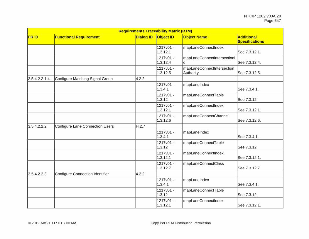
NTCIP 1202 v03A.28 Page 647
© 2019 AASHTO / ITE / NEMA Copy Per RTM Distribution Permission
Requirements Traceability Matrix (RTM) FR ID Functional Requirement Dialog ID Object ID Object Name Additional
Specifications
1217v01 - 1.3.12.1
mapLaneConnectIndex See 7.3.12.1.
1217v01 - 1.3.12.4
mapLaneConnectIntersectionId See 7.3.12.4.
1217v01 - 1.3.12.5
mapLaneConnectIntersectionAuthority See 7.3.12.5.
3.5.4.2.2.1.4 Configure Matching Signal Group 4.2.2
1217v01 - 1.3.4.1
mapLaneIndex See 7.3.4.1.
1217v01 - 1.3.12
mapLaneConnectTable See 7.3.12.
1217v01 - 1.3.12.1
mapLaneConnectIndex See 7.3.12.1.
1217v01 - 1.3.12.6
mapLaneConnectChannel See 7.3.12.6.
3.5.4.2.2.2 Configure Lane Connection Users H.2.7
1217v01 - 1.3.4.1
mapLaneIndex See 7.3.4.1.
1217v01 - 1.3.12
mapLaneConnectTable See 7.3.12.
1217v01 - 1.3.12.1
mapLaneConnectIndex See 7.3.12.1.
1217v01 - 1.3.12.7
mapLaneConnectClass See 7.3.12.7.
3.5.4.2.2.3 Configure Connection Identifier 4.2.2
1217v01 - 1.3.4.1
mapLaneIndex See 7.3.4.1.
1217v01 - 1.3.12
mapLaneConnectTable See 7.3.12.
1217v01 - 1.3.12.1
mapLaneConnectIndex See 7.3.12.1.

NTCIP 1202 v03A.28 Page 648
Copy Per RTM Distribution Permission © 2019 AASHTO / ITE / NEMA
Requirements Traceability Matrix (RTM) FR ID Functional Requirement Dialog ID Object ID Object Name Additional
Specifications
1217v01 - 1.3.12.8
mapLaneConnectManeuverNumber See 7.3.12.8.
3.5.4.2.2.4 Configure MAP Plans 4.2.2
1217v01 - 1.3.8
mapPlanTable See 7.3.18.
1217v01 - 1.3.8.1
mapPlanIndex See 7.3.18.1.
1217v01 - 1.3.8.2
mapPlanLanes See 7.3.18.2.
1217v01 - 1.3.8.3
mapPlanCRC See 7.3.18.3.
3.5.4.2.2.5 Determine Maximum Number of Signal Groups Supported G.1
5.9.1 maxChannels
3.5.4.2.2.6 Determine Maximum Number of Lane Connections Supported G.1
1217v01 - 1.3.11
maxLaneConnects See 7.3.11.
3.5.4.2.2.7 Command MAP Plans 4.2.11 5.18.1.4 mapActivatePlan 5.18.1.5 mapActivatePlanError
3.5.4.2.3 Manage Collection of Connected Devices Data Requirements
3.5.4.2.3.1 Configure Connected Device Detector Requirements
3.5.4.2.3.1.1 Enable Connected Device Detection G.3 5.18.2.1 cvDetectionEnable 3.5.4.2.3.1.2 Enable Connected Device Detector 4.2.7 5.18.2.2 maxCvDetectionZones 5.18.2.3 ascCvDetectorTable
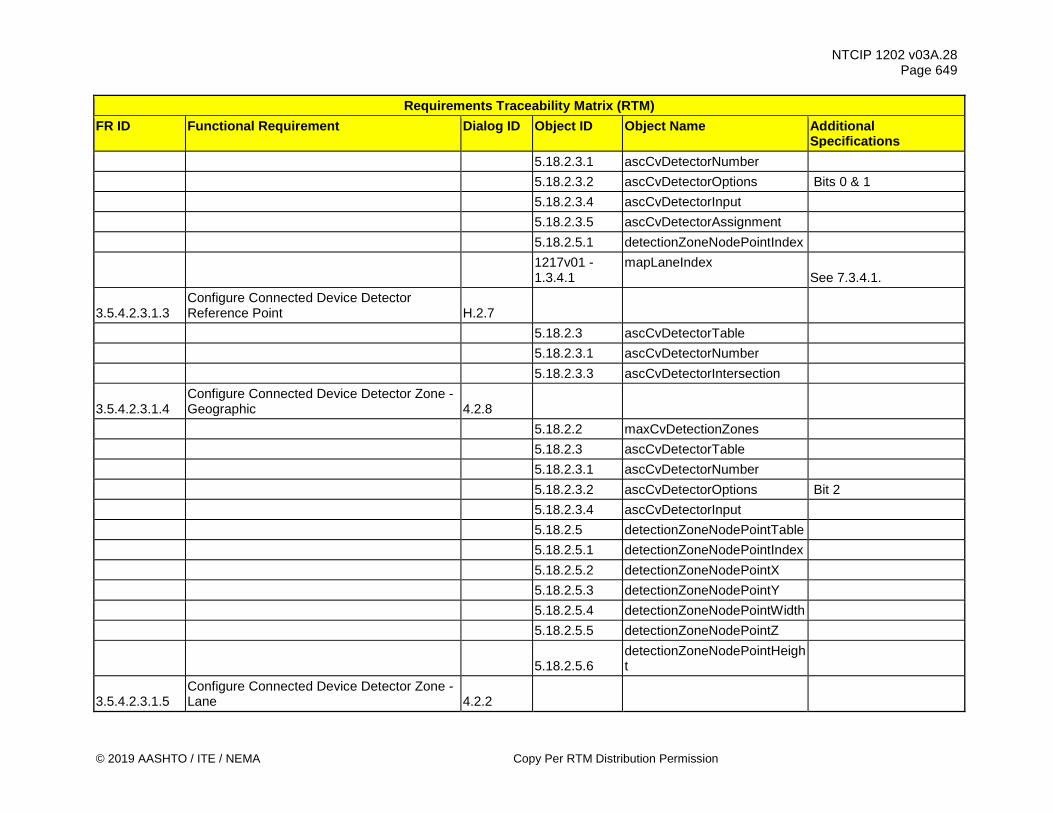
NTCIP 1202 v03A.28 Page 649
© 2019 AASHTO / ITE / NEMA Copy Per RTM Distribution Permission
Requirements Traceability Matrix (RTM) FR ID Functional Requirement Dialog ID Object ID Object Name Additional
Specifications 5.18.2.3.1 ascCvDetectorNumber 5.18.2.3.2 ascCvDetectorOptions Bits 0 & 1 5.18.2.3.4 ascCvDetectorInput 5.18.2.3.5 ascCvDetectorAssignment 5.18.2.5.1 detectionZoneNodePointIndex
1217v01 - 1.3.4.1
mapLaneIndex See 7.3.4.1.
3.5.4.2.3.1.3 Configure Connected Device Detector Reference Point H.2.7
5.18.2.3 ascCvDetectorTable 5.18.2.3.1 ascCvDetectorNumber 5.18.2.3.3 ascCvDetectorIntersection
3.5.4.2.3.1.4 Configure Connected Device Detector Zone - Geographic 4.2.8
5.18.2.2 maxCvDetectionZones 5.18.2.3 ascCvDetectorTable 5.18.2.3.1 ascCvDetectorNumber 5.18.2.3.2 ascCvDetectorOptions Bit 2 5.18.2.3.4 ascCvDetectorInput 5.18.2.5 detectionZoneNodePointTable 5.18.2.5.1 detectionZoneNodePointIndex 5.18.2.5.2 detectionZoneNodePointX 5.18.2.5.3 detectionZoneNodePointY 5.18.2.5.4 detectionZoneNodePointWidth 5.18.2.5.5 detectionZoneNodePointZ
5.18.2.5.6 detectionZoneNodePointHeight
3.5.4.2.3.1.5 Configure Connected Device Detector Zone - Lane 4.2.2

NTCIP 1202 v03A.28 Page 650
Copy Per RTM Distribution Permission © 2019 AASHTO / ITE / NEMA
Requirements Traceability Matrix (RTM) FR ID Functional Requirement Dialog ID Object ID Object Name Additional
Specifications 5.18.2.3 ascCvDetectorTable 5.18.2.3.1 ascCvDetectorNumber 5.18.2.3.2 ascCvDetectorOptions Bit 2 5.18.2.3.4 ascCvDetectorInput 3.5.4.2.3.1.6 Configure Connected Device Data Filters H.2.7 5.18.2.3 ascCvDetectorTable 5.18.2.3.1 ascCvDetectorNumber 5.18.2.3.2 ascCvDetectorOptions Bits 0, 1, 5, and 6 5.18.2.3.7 ascCvDetectorUserClass 5.18.2.3.8 ascCvDetectorHeading 5.18.2.3.9 ascCvDetectorMinSpeed 5.18.2.3.10 ascCvDetectorMaxSpeed 5.18.2.3.11 ascCvDetectorMinSize 5.18.2.3.12 ascCvDetectorMaxSize 5.18.2.3.13 ascCvDetectorFlags
3.5.4.2.3.1.7 Configure Connected Device Detector Assignments H.2.7
5.18.2.3 ascCvDetectorTable 5.18.2.3.1 ascCvDetectorNumber 5.18.2.3.5 ascCvDetectorAssignment
3.5.4.2.3.1.8 Determine Maximum Number of Connected Device Detectors Supported G.1
5.18.2.2 maxCvDetectionZones
3.5.4.2.3.1.9 Determine Maximum Number of Connected Device Detectors Node Points Supported G.1
5.18.2.4 maxDetectionZoneNodePoints
3.5.4.2.3.2 Configure Connected Device Detector Output Requirements
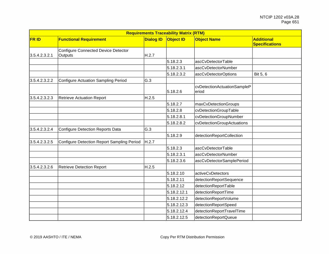
NTCIP 1202 v03A.28 Page 651
© 2019 AASHTO / ITE / NEMA Copy Per RTM Distribution Permission
Requirements Traceability Matrix (RTM) FR ID Functional Requirement Dialog ID Object ID Object Name Additional
Specifications
3.5.4.2.3.2.1 Configure Connected Device Detector Outputs H.2.7
5.18.2.3 ascCvDetectorTable 5.18.2.3.1 ascCvDetectorNumber 5.18.2.3.2 ascCvDetectorOptions Bit 5, 6 3.5.4.2.3.2.2 Configure Actuation Sampling Period G.3
5.18.2.6 cvDetectionActuationSamplePeriod
3.5.4.2.3.2.3 Retrieve Actuation Report H.2.5 5.18.2.7 maxCvDetectionGroups 5.18.2.8 cvDetectionGroupTable 5.18.2.8.1 cvDetectionGroupNumber 5.18.2.8.2 cvDetectionGroupActuations 3.5.4.2.3.2.4 Configure Detection Reports Data G.3 5.18.2.9 detectionReportCollection 3.5.4.2.3.2.5 Configure Detection Report Sampling Period H.2.7 5.18.2.3 ascCvDetectorTable 5.18.2.3.1 ascCvDetectorNumber 5.18.2.3.6 ascCvDetectorSamplePeriod 3.5.4.2.3.2.6 Retrieve Detection Report H.2.5 5.18.2.10 activeCvDetectors 5.18.2.11 detectionReportSequence 5.18.2.12 detectionReportTable 5.18.2.12.1 detectionReportTime 5.18.2.12.2 detectionReportVolume 5.18.2.12.3 detectionReportSpeed 5.18.2.12.4 detectionReportTravelTime 5.18.2.12.5 detectionReportQueue
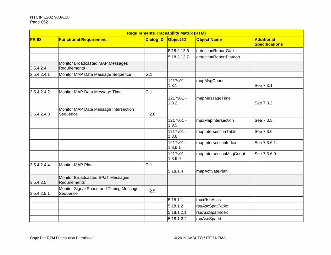
NTCIP 1202 v03A.28 Page 652
Copy Per RTM Distribution Permission © 2019 AASHTO / ITE / NEMA
Requirements Traceability Matrix (RTM) FR ID Functional Requirement Dialog ID Object ID Object Name Additional
Specifications 5.18.2.12.6 detectionReportGap 5.18.2.12.7 detectionReportPlatoon
3.5.4.2.4 Monitor Broadcasted MAP Messages Requirements
3.5.4.2.4.1 Monitor MAP Data Message Sequence G.1
1217v01 - 1.3.1
mapMsgCount See 7.3.1.
3.5.4.2.4.2 Monitor MAP Data Message Time G.1
1217v01 - 1.3.2
mapMessageTime See 7.3.2.
3.5.4.2.4.3 Monitor MAP Data Message Intersection Sequence H.2.6
1217v01 - 1.3.5
maxMapIntersection See 7.3.5.
1217v01 - 1.3.6
mapIntersectionTable See 7.3.6.
1217v01 - 1.3.6.1
mapIntersectionIndex See 7.3.6.1.
1217v01 - 1.3.6.9
mapIntersectionMsgCount See 7.3.6.9.
3.5.4.2.4.4 Monitor MAP Plan G.1 5.18.1.4 mapActivatePlan
3.5.4.2.5 Monitor Broadcasted SPaT Messages Requirements
3.5.4.2.5.1 Monitor Signal Phase and Timing Message Sequence H.2.5
5.18.1.1 maxRsuAscs 5.18.1.2 rsuAscSpatTable 5.18.1.2.1 rsuAscSpatIndex 5.18.1.2.2 rsuAscSpatId

NTCIP 1202 v03A.28 Page 653
© 2019 AASHTO / ITE / NEMA Copy Per RTM Distribution Permission
Requirements Traceability Matrix (RTM) FR ID Functional Requirement Dialog ID Object ID Object Name Additional
Specifications 5.18.1.2.3 rsuAscSpatMsgCount
3.5.4.2.5.2 Monitor Signal Phase and Timing Message Timestamp G.1
5.18.1.3 rsuSpatMinuteOfTheYear
3.5.4.2.5.3 Monitor Intersection SPaT Message Timestamp H.2.5
5.18.1.1 maxRsuAscs 5.18.1.2 rsuAscSpatTable 5.18.1.2.1 rsuAscSpatIndex 5.18.1.2.4 rsuAscSpatMinuteOfTheYear 5.18.1.2.5 rsuAscSpatMilliseconds 3.5.4.2.5.4 Monitor Enabled Lanes H.2.6 5.18.1.1 maxRsuAscs 5.18.1.2 rsuAscSpatTable 5.18.1.2.1 rsuAscSpatIndex 5.18.1.2.6 rsuAscSpatEnabledLanes
3.5.4.3 ASC - CV Roadside Process Interface Requirements
3.5.4.3.1 Exchange Current and Next Movement Information Requirements
3.5.4.3.1.1 Provide Current and Next Movement Information Requirements
3.5.4.3.1.1.1 Provide Intersection Identifier H.2.7
1217v01 - 1.3.6
mapIntersectionTable See 7.3.6.
1217v01 - 1.3.6.1
mapIntersectionIndex See 7.3.6.1.
1217v01 - 1.3.6.2
mapIntersectionId See 7.3.6.2.
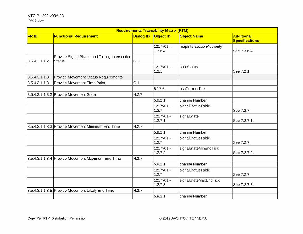
NTCIP 1202 v03A.28 Page 654
Copy Per RTM Distribution Permission © 2019 AASHTO / ITE / NEMA
Requirements Traceability Matrix (RTM) FR ID Functional Requirement Dialog ID Object ID Object Name Additional
Specifications
1217v01 - 1.3.6.4
mapIntersectionAuthority See 7.3.6.4.
3.5.4.3.1.1.2 Provide Signal Phase and Timing Intersection Status G.3
1217v01 - 1.2.1
spatStatus See 7.2.1.
3.5.4.3.1.1.3 Provide Movement Status Requirements 3.5.4.3.1.1.3.1 Provide Movement Time Point G.1 5.17.6 ascCurrentTick 3.5.4.3.1.1.3.2 Provide Movement State H.2.7 5.9.2.1 channelNumber
1217v01 - 1.2.7
signalStatusTable See 7.2.7.
1217v01 - 1.2.7.1
signalState See 7.2.7.1.
3.5.4.3.1.1.3.3 Provide Movement Minimum End Time H.2.7 5.9.2.1 channelNumber
1217v01 - 1.2.7
signalStatusTable See 7.2.7.
1217v01 - 1.2.7.2
signalStateMinEndTick See 7.2.7.2.
3.5.4.3.1.1.3.4 Provide Movement Maximum End Time H.2.7 5.9.2.1 channelNumber
1217v01 - 1.2.7
signalStatusTable See 7.2.7.
1217v01 - 1.2.7.3
signalStateMaxEndTick See 7.2.7.3.
3.5.4.3.1.1.3.5 Provide Movement Likely End Time H.2.7 5.9.2.1 channelNumber

NTCIP 1202 v03A.28 Page 655
© 2019 AASHTO / ITE / NEMA Copy Per RTM Distribution Permission
Requirements Traceability Matrix (RTM) FR ID Functional Requirement Dialog ID Object ID Object Name Additional
Specifications
1217v01 - 1.2.7
signalStatusTable See 7.2.7.
1217v01 - 1.2.7.4
signalStateLikelyEndTick See 7.2.7.4.
3.5.4.3.1.1.3.6 Provide Movement Likely End Time Confidence H.2.7
5.9.2.1 channelNumber
1217v01 - 1.2.7
signalStatusTable See 7.2.7.
1217v01 - 1.2.7.5
signalStateTickConfidence See 7.2.7.5.
3.5.4.3.1.1.3.7 Provide Movement Next Occurrence H.2.7 5.9.2.1 channelNumber
1217v01 - 1.2.7
signalStatusTable See 7.2.7.
1217v01 - 1.2.7.6
signalNextTick See 7.2.7.6.
3.5.4.3.1.1.3.8 Provide Movement Status G.1
1217v01 - 1.2.8
signalStatusBlock See 7.2.8.
3.5.4.3.1.1.4 Provide Movement Assistance Requirements 3.5.4.3.1.1.4.1 Provide Lane Connection Queue Length H.2.7 5.9.2.1 channelNumber
1217v01 - 1.2.5
movementManeuverTable See 7.2.5.
1217v01 - 1.2.5.1
movementManeuverIndex See 7.2.5.1.
1217v01 - 1.2.5.4
movementManeuverQueue See 7.2.5.4.

NTCIP 1202 v03A.28 Page 656
Copy Per RTM Distribution Permission © 2019 AASHTO / ITE / NEMA
Requirements Traceability Matrix (RTM) FR ID Functional Requirement Dialog ID Object ID Object Name Additional
Specifications
3.5.4.3.1.1.4.2 Provide Lane Connection Available Storage Length H.2.7
5.9.2.1 channelNumber
1217v01 - 1.2.5
movementManeuverTable See 7.2.5.
1217v01 - 1.2.5.1
movementManeuverIndex See 7.2.5.1.
1217v01 - 1.2.5.5
movementManeuverStorage See 7.2.5.5.
3.5.4.3.1.1.4.3 Provide Lane Connection Stop Line Wait H.2.7 5.9.2.1 channelNumber
1217v01 - 1.2.5
movementManeuverTable See 7.2.5.
1217v01 - 1.2.5.1
movementManeuverIndex See 7.2.5.1.
1217v01 - 1.2.5.6
movementManeuverStatus See 7.2.5.6.
3.5.4.3.1.1.4.4 Provide Lane Connection Traveler Detection H.2.7 5.9.2.1 channelNumber
1217v01 - 1.2.5
movementManeuverTable See 7.2.5.
1217v01 - 1.2.5.1
movementManeuverIndex See 7.2.5.1.
1217v01 - 1.2.5.6
movementManeuverStatus See 7.2.5.6.
3.5.4.3.1.1.4.5 Provide Lane Connection State H.2.7 5.9.2.1 channelNumber
1217v01 - 1.2.5
movementManeuverTable See 7.2.5.

NTCIP 1202 v03A.28 Page 657
© 2019 AASHTO / ITE / NEMA Copy Per RTM Distribution Permission
Requirements Traceability Matrix (RTM) FR ID Functional Requirement Dialog ID Object ID Object Name Additional
Specifications
1217v01 - 1.2.5.1
movementManeuverIndex See 7.2.5.1.
1217v01 - 1.2.5.3
movementManeuverState See 7.2.5.3.
3.5.4.3.1.1.4.6 Provide Lane Connection Status G.1
1217v01 - 1.2.9
movementManeuverStatusBlock See 7.2.9.
3.5.4.3.1.1.5 Provide Advisory Speed Requirements 3.5.4.3.1.1.5.1 Provide Advisory Speed Type H.2.7 5.9.2 channelTable 5.9.2.1 channelNumber
1217v01 - 1.2.3
advisorySpeedTable See 7.2.3.
1217v01 - 1.2.3.1
advisorySpeedIndex See 7.2.3.1.
1217v01 - 1.2.3.2
advisorySpeedType See 7.2.3.2.
3.5.4.3.1.1.5.2 Provide Advisory Speed H.2.7 5.9.2 channelTable 5.9.2.1 channelNumber
1217v01 - 1.2.3
advisorySpeedTable See 7.2.3.
1217v01 - 1.2.3.1
advisorySpeedIndex See 7.2.3.1.
1217v01 - 1.2.3.3
advisorySpeedAdvice See 7.2.3.3.
3.5.4.3.1.1.5.3 Provide Advisory Speed Zone H.2.7 5.9.2 channelTable 5.9.2.1 channelNumber

NTCIP 1202 v03A.28 Page 658
Copy Per RTM Distribution Permission © 2019 AASHTO / ITE / NEMA
Requirements Traceability Matrix (RTM) FR ID Functional Requirement Dialog ID Object ID Object Name Additional
Specifications
1217v01 - 1.2.3
advisorySpeedTable See 7.2.3.
1217v01 - 1.2.3.1
advisorySpeedIndex See 7.2.3.1.
1217v01 - 1.2.3.4
advisorySpeedZoneLength See 7.2.3.4.
3.5.4.3.1.1.5.4 Provide Advisory Speed Vehicle Type H.2.7 5.9.2 channelTable 5.9.2.1 channelNumber
1217v01 - 1.2.3
advisorySpeedTable See 7.2.3.
1217v01 - 1.2.3.1
advisorySpeedIndex See 7.2.3.1.
1217v01 - 1.2.3.5
advisorySpeedClass See 7.2.3.5.
3.5.4.3.1.1.5.5 Provide Advisory Speed Confidence Level H.2.7
1217v01 - 1.2.3
advisorySpeedTable See 7.2.3.
1217v01 - 1.2.3.1
advisorySpeedIndex See 7.2.3.1.
1217v01 - 1.2.3.6
advisorySpeedConfidence See 7.2.3.6.
3.5.4.3.1.1.6 Provide Intersection Channel Assignment H.2.7 5.9.2 channelTable 5.9.2.1 channelNumber 5.9.2.8 channelIntersectionId
3.5.4.3.1.2 Retrieve Current and Next Movement Information Requirements
3.5.4.3.1.2.1 Retrieve Intersection Identifier H.2.5
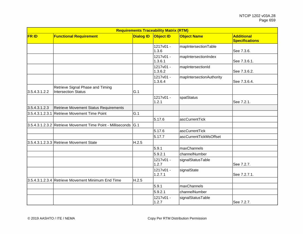
NTCIP 1202 v03A.28 Page 659
© 2019 AASHTO / ITE / NEMA Copy Per RTM Distribution Permission
Requirements Traceability Matrix (RTM) FR ID Functional Requirement Dialog ID Object ID Object Name Additional
Specifications
1217v01 - 1.3.6
mapIntersectionTable See 7.3.6.
1217v01 - 1.3.6.1
mapIntersectionIndex See 7.3.6.1.
1217v01 - 1.3.6.2
mapIntersectionId See 7.3.6.2.
1217v01 - 1.3.6.4
mapIntersectionAuthority See 7.3.6.4.
3.5.4.3.1.2.2 Retrieve Signal Phase and Timing Intersection Status G.1
1217v01 - 1.2.1
spatStatus See 7.2.1.
3.5.4.3.1.2.3 Retrieve Movement Status Requirements 3.5.4.3.1.2.3.1 Retrieve Movement Time Point G.1 5.17.6 ascCurrentTick 3.5.4.3.1.2.3.2 Retrieve Movement Time Point - Milliseconds G.1 5.17.6 ascCurrentTick 5.17.7 ascCurrentTickMsOffset 3.5.4.3.1.2.3.3 Retrieve Movement State H.2.5 5.9.1 maxChannels 5.9.2.1 channelNumber
1217v01 - 1.2.7
signalStatusTable See 7.2.7.
1217v01 - 1.2.7.1
signalState See 7.2.7.1.
3.5.4.3.1.2.3.4 Retrieve Movement Minimum End Time H.2.5 5.9.1 maxChannels 5.9.2.1 channelNumber
1217v01 - 1.2.7
signalStatusTable See 7.2.7.

NTCIP 1202 v03A.28 Page 660
Copy Per RTM Distribution Permission © 2019 AASHTO / ITE / NEMA
Requirements Traceability Matrix (RTM) FR ID Functional Requirement Dialog ID Object ID Object Name Additional
Specifications
1217v01 - 1.2.7.2
signalStateMinEndTick See 7.2.7.2.
3.5.4.3.1.2.3.5 Retrieve Movement Maximum End Time H.2.5 5.9.1 maxChannels 5.9.2.1 channelNumber
1217v01 - 1.2.7
signalStatusTable See 7.2.7.
1217v01 - 1.2.7.3
signalStateMaxEndTick See 7.2.7.3.
3.5.4.3.1.2.3.6 Retrieve Movement Likely End Time H.2.5 5.9.1 maxChannels 5.9.2.1 channelNumber
1217v01 - 1.2.7
signalStatusTable See 7.2.7.
1217v01 - 1.2.7.4
signalStateLikelyEndTick See 7.2.7.4.
3.5.4.3.1.2.3.7 Retrieve Movement Likely End Time Confidence H.2.5
5.9.1 maxChannels 5.9.2.1 channelNumber
1217v01 - 1.2.7
signalStatusTable See 7.2.7.
1217v01 - 1.2.7.5
signalStateTickConfidence See 7.2.7.5.
3.5.4.3.1.2.3.8 Retrieve Movement Next Occurrence H.2.5 5.9.1 maxChannels 5.9.2.1 channelNumber
1217v01 - 1.2.7
signalStatusTable See 7.2.7.
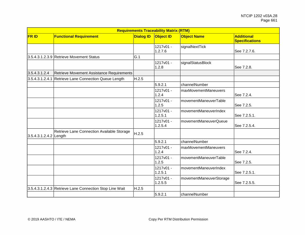
NTCIP 1202 v03A.28 Page 661
© 2019 AASHTO / ITE / NEMA Copy Per RTM Distribution Permission
Requirements Traceability Matrix (RTM) FR ID Functional Requirement Dialog ID Object ID Object Name Additional
Specifications
1217v01 - 1.2.7.6
signalNextTick See 7.2.7.6.
3.5.4.3.1.2.3.9 Retrieve Movement Status G.1
1217v01 - 1.2.8
signalStatusBlock See 7.2.8.
3.5.4.3.1.2.4 Retrieve Movement Assistance Requirements 3.5.4.3.1.2.4.1 Retrieve Lane Connection Queue Length H.2.5 5.9.2.1 channelNumber
1217v01 - 1.2.4
maxMovementManeuvers See 7.2.4.
1217v01 - 1.2.5
movementManeuverTable See 7.2.5.
1217v01 - 1.2.5.1
movementManeuverIndex See 7.2.5.1.
1217v01 - 1.2.5.4
movementManeuverQueue See 7.2.5.4.
3.5.4.3.1.2.4.2 Retrieve Lane Connection Available Storage Length H.2.5
5.9.2.1 channelNumber
1217v01 - 1.2.4
maxMovementManeuvers See 7.2.4.
1217v01 - 1.2.5
movementManeuverTable See 7.2.5.
1217v01 - 1.2.5.1
movementManeuverIndex See 7.2.5.1.
1217v01 - 1.2.5.5
movementManeuverStorage See 7.2.5.5.
3.5.4.3.1.2.4.3 Retrieve Lane Connection Stop Line Wait H.2.5 5.9.2.1 channelNumber

NTCIP 1202 v03A.28 Page 662
Copy Per RTM Distribution Permission © 2019 AASHTO / ITE / NEMA
Requirements Traceability Matrix (RTM) FR ID Functional Requirement Dialog ID Object ID Object Name Additional
Specifications
1217v01 - 1.2.4
maxMovementManeuvers See 7.2.4.
1217v01 - 1.2.5
movementManeuverTable See 7.2.5.
1217v01 - 1.2.5.1
movementManeuverIndex See 7.2.5.1.
1217v01 - 1.2.5.6
movementManeuverStatus See 7.2.5.6.
3.5.4.3.1.2.4.4 Retrieve Lane Connection Traveler Detection H.2.5 5.9.2.1 channelNumber
1217v01 - 1.2.4
maxMovementManeuvers See 7.2.4.
1217v01 - 1.2.5
movementManeuverTable See 7.2.5.
1217v01 - 1.2.5.1
movementManeuverIndex See 7.2.5.1.
1217v01 - 1.2.5.6
movementManeuverStatus See 7.2.5.6.
3.5.4.3.1.2.4.5 Retrieve Lane Connection State H.2.5 5.9.2.1 channelNumber
1217v01 - 1.2.4
maxMovementManeuvers See 7.2.4.
1217v01 - 1.2.5
movementManeuverTable See 7.2.5.
1217v01 - 1.2.5.1
movementManeuverIndex See 7.2.5.1.
1217v01 - 1.2.5.3
movementManeuverState See 7.2.5.3.
3.5.4.3.1.2.4.6 Retrieve Lane Connection Status G.1
1217v01 - 1.2.9
movementManeuverStatusBlock See 7.2.9.

NTCIP 1202 v03A.28 Page 663
© 2019 AASHTO / ITE / NEMA Copy Per RTM Distribution Permission
Requirements Traceability Matrix (RTM) FR ID Functional Requirement Dialog ID Object ID Object Name Additional
Specifications 3.5.4.3.1.2.5 Retrieve Advisory Speed Requirements 3.5.4.3.1.2.5.1 Retrieve Advisory Speed Type H.2.5 5.9.1 maxChannels 5.9.2 channelTable 5.9.2.1 channelNumber
1217v01 - 1.2.3
advisorySpeedTable See 7.2.3.
1217v01 - 1.2.3.1
advisorySpeedIndex See 7.2.3.1.
1217v01 - 1.2.3.2
advisorySpeedType See 7.2.3.2.
3.5.4.3.1.2.5.2 Retrieve Advisory Speed H.2.5 5.9.1 maxChannels 5.9.2 channelTable 5.9.2.1 channelNumber
1217v01 - 1.2.3
advisorySpeedTable See 7.2.3.
1217v01 - 1.2.3.1
advisorySpeedIndex See 7.2.3.1.
1217v01 - 1.2.3.3
advisorySpeedAdvice See 7.2.3.3.
3.5.4.3.1.2.5.3 Retrieve Advisory Speed Zone H.2.5 5.9.1 maxChannels 5.9.2 channelTable 5.9.2.1 channelNumber
1217v01 - 1.2.3
advisorySpeedTable See 7.2.3.
1217v01 - 1.2.3.1
advisorySpeedIndex See 7.2.3.1.

NTCIP 1202 v03A.28 Page 664
Copy Per RTM Distribution Permission © 2019 AASHTO / ITE / NEMA
Requirements Traceability Matrix (RTM) FR ID Functional Requirement Dialog ID Object ID Object Name Additional
Specifications
1217v01 - 1.2.3.4
advisorySpeedZoneLength See 7.2.3.4.
3.5.4.3.1.2.5.4 Retrieve Advisory Speed Vehicle Type H.2.5 5.9.1 maxChannels 5.9.2 channelTable 5.9.2.1 channelNumber
1217v01 - 1.2.3
advisorySpeedTable See 7.2.3.
1217v01 - 1.2.3.1
advisorySpeedIndex See 7.2.3.1.
1217v01 - 1.2.3.5
advisorySpeedClass See 7.2.3.5.
3.5.4.3.1.2.5.5 Retrieve Advisory Speed Confidence Level H.2.5
1217v01 - 1.2.2
maxAdvisorySpeeds See 7.2.2.
1217v01 - 1.2.3
advisorySpeedTable See 7.2.3.
1217v01 - 1.2.3.1
advisorySpeedIndex See 7.2.3.1.
1217v01 - 1.2.3.6
advisorySpeedConfidence See 7.2.3.6.
3.5.4.3.1.2.6 Retrieve Intersection Channel Assignment H.2.5 5.9.1 maxChannels 5.9.2 channelTable 5.9.2.1 channelNumber 5.9.2.8 channelIntersectionId
3.5.4.3.2 Exchange Next Occurrence of a Movement Requirements
3.5.4.3.2.1 Provide Movement Next Occurrence H.2.7 5.9.1 maxChannels
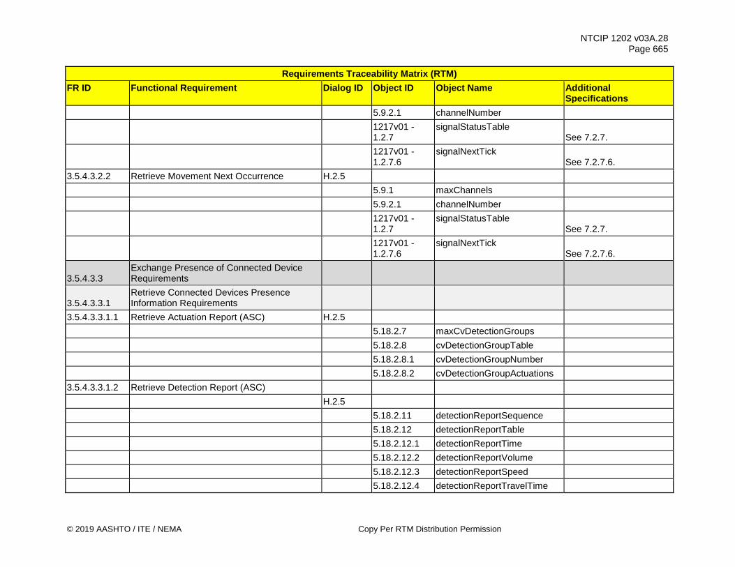
NTCIP 1202 v03A.28 Page 665
© 2019 AASHTO / ITE / NEMA Copy Per RTM Distribution Permission
Requirements Traceability Matrix (RTM) FR ID Functional Requirement Dialog ID Object ID Object Name Additional
Specifications 5.9.2.1 channelNumber
1217v01 - 1.2.7
signalStatusTable See 7.2.7.
1217v01 - 1.2.7.6
signalNextTick See 7.2.7.6.
3.5.4.3.2.2 Retrieve Movement Next Occurrence H.2.5 5.9.1 maxChannels 5.9.2.1 channelNumber
1217v01 - 1.2.7
signalStatusTable See 7.2.7.
1217v01 - 1.2.7.6
signalNextTick See 7.2.7.6.
3.5.4.3.3 Exchange Presence of Connected Device Requirements
3.5.4.3.3.1 Retrieve Connected Devices Presence Information Requirements
3.5.4.3.3.1.1 Retrieve Actuation Report (ASC) H.2.5 5.18.2.7 maxCvDetectionGroups 5.18.2.8 cvDetectionGroupTable 5.18.2.8.1 cvDetectionGroupNumber 5.18.2.8.2 cvDetectionGroupActuations 3.5.4.3.3.1.2 Retrieve Detection Report (ASC) H.2.5 5.18.2.11 detectionReportSequence 5.18.2.12 detectionReportTable 5.18.2.12.1 detectionReportTime 5.18.2.12.2 detectionReportVolume 5.18.2.12.3 detectionReportSpeed 5.18.2.12.4 detectionReportTravelTime
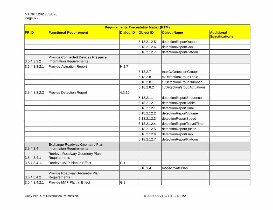
NTCIP 1202 v03A.28 Page 666
Copy Per RTM Distribution Permission © 2019 AASHTO / ITE / NEMA
Requirements Traceability Matrix (RTM) FR ID Functional Requirement Dialog ID Object ID Object Name Additional
Specifications 5.18.2.12.5 detectionReportQueue 5.18.2.12.6 detectionReportGap 5.18.2.12.7 detectionReportPlatoon
3.5.4.3.3.2 Provide Connected Devices Presence Information Requirements
3.5.4.3.3.2.1 Provide Actuation Report H.2.7 5.18.2.7 maxCvDetectionGroups 5.18.2.8 cvDetectionGroupTable 5.18.2.8.1 cvDetectionGroupNumber 5.18.2.8.2 cvDetectionGroupActuations 3.5.4.3.3.2.2 Provide Detection Report 4.2.10 5.18.2.11 detectionReportSequence 5.18.2.12 detectionReportTable 5.18.2.12.1 detectionReportTime 5.18.2.12.2 detectionReportVolume 5.18.2.12.3 detectionReportSpeed 5.18.2.12.4 detectionReportTravelTime 5.18.2.12.5 detectionReportQueue 5.18.2.12.6 detectionReportGap 5.18.2.12.7 detectionReportPlatoon
3.5.4.3.4 Exchange Roadway Geometry Plan Information Requirements
3.5.4.3.4.1 Retrieve Roadway Geometry Plan Requirements
3.5.4.3.4.1.1 Retrieve MAP Plan in Effect G.1 5.18.1.4 mapActivatePlan
3.5.4.3.4.2 Provide Roadway Geometry Plan Requirements
3.5.4.3.4.2.1 Provide MAP Plan in Effect G.3

NTCIP 1202 v03A.28 Page 667
© 2019 AASHTO / ITE / NEMA Copy Per RTM Distribution Permission
Requirements Traceability Matrix (RTM) FR ID Functional Requirement Dialog ID Object ID Object Name Additional
Specifications 5.18.1.4 mapActivatePlan 3.5.4.3.4.3 Confirm MAP Plan Compatibility 4.2.12 5.16.3.1 rsuPortIndex 5.17.5 spatPortTable 5.17.5.3 spatPortMapActivationCode 5.18.1.4 mapActivatePlan 3.5.5 Backward Compatibility Requirements
3.5.5.1 NTCIP 1202 v01 - Configure Special Function State H.2.5
5.4.13 maxSpecialFunctionOutputs 5.4.14 specialFunctionOutputTable 5.4.14.1 specialFunctionOutputNumber 5.4.14.2 specialFunctionOutputState
3.6 Supplemental Non-communications Requirements
3.6.1 Response Time for Requests See Requirement 3.6.1 in
the PRL
3.6.2 Condition-based Maximum Transmission Start Time
See Requirement 3.6.2 in the PRL
3.6.3 Signal Phase and Timing Data Performance Requirements
3.6.3.1 SPaT Maximum Transmission Start Time See Requirement 3.6.3.1
in the PRL
3.6.3.2 Movement Time Point Minimum Transmission Rate
See Requirement 3.6.3.2 in the PRL
3.6.3.3 SPaT-data Request Transmission Rate See Requirement 3.6.3.3
in the PRL
3.6.3.4 Condition-based SPaT Maximum Transmission Start Time
See Requirement 3.6.3.4 in the PRL
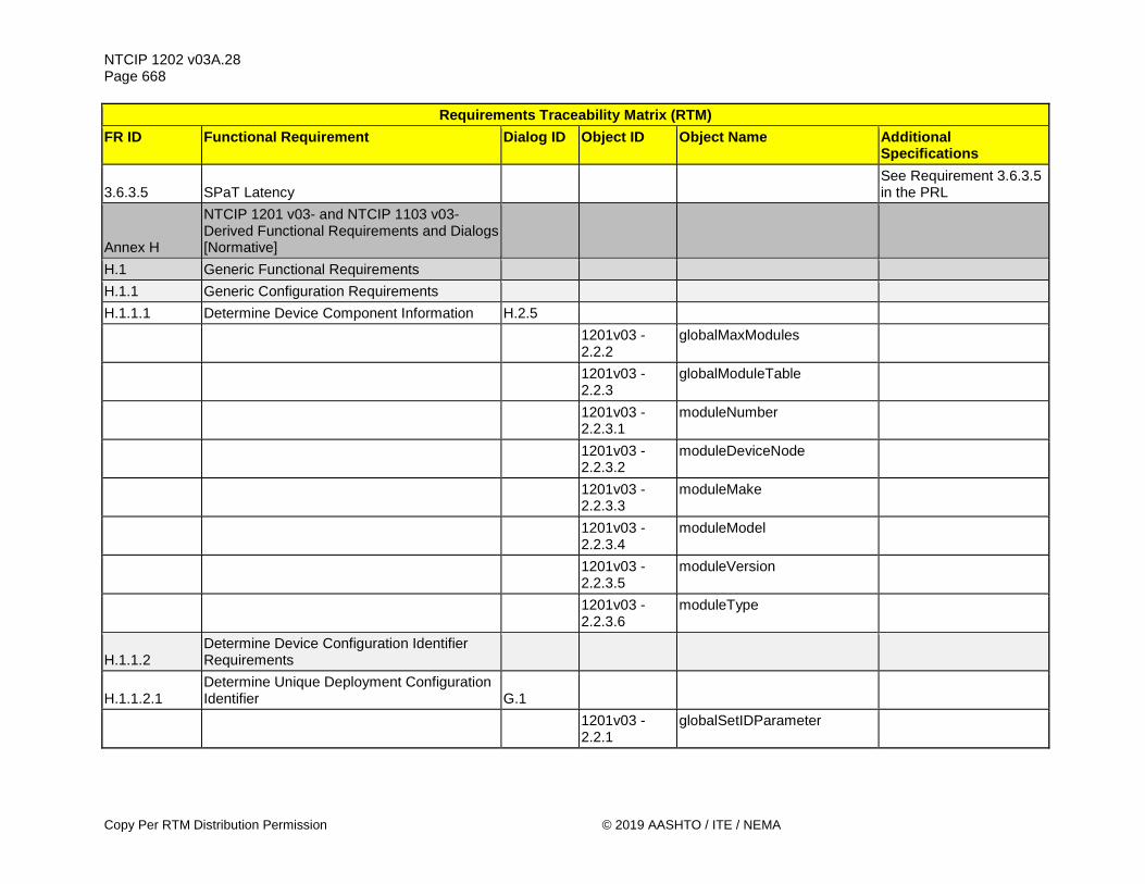
NTCIP 1202 v03A.28 Page 668
Copy Per RTM Distribution Permission © 2019 AASHTO / ITE / NEMA
Requirements Traceability Matrix (RTM) FR ID Functional Requirement Dialog ID Object ID Object Name Additional
Specifications
3.6.3.5 SPaT Latency See Requirement 3.6.3.5
in the PRL
Annex H
NTCIP 1201 v03- and NTCIP 1103 v03-Derived Functional Requirements and Dialogs [Normative]
H.1 Generic Functional Requirements H.1.1 Generic Configuration Requirements H.1.1.1 Determine Device Component Information H.2.5
1201v03 - 2.2.2
globalMaxModules
1201v03 - 2.2.3
globalModuleTable
1201v03 - 2.2.3.1
moduleNumber
1201v03 - 2.2.3.2
moduleDeviceNode
1201v03 - 2.2.3.3
moduleMake
1201v03 - 2.2.3.4
moduleModel
1201v03 - 2.2.3.5
moduleVersion
1201v03 - 2.2.3.6
moduleType
H.1.1.2 Determine Device Configuration Identifier Requirements
H.1.1.2.1 Determine Unique Deployment Configuration Identifier G.1
1201v03 - 2.2.1
globalSetIDParameter
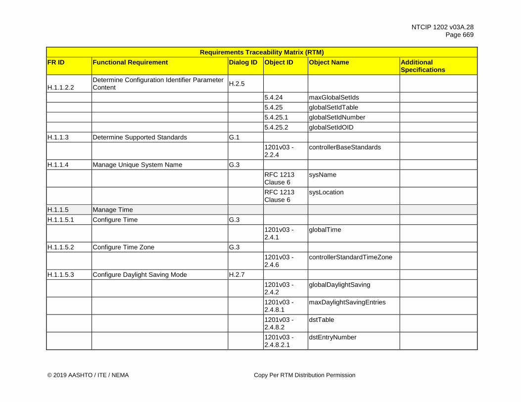
NTCIP 1202 v03A.28 Page 669
© 2019 AASHTO / ITE / NEMA Copy Per RTM Distribution Permission
Requirements Traceability Matrix (RTM) FR ID Functional Requirement Dialog ID Object ID Object Name Additional
Specifications
H.1.1.2.2 Determine Configuration Identifier Parameter Content H.2.5
5.4.24 maxGlobalSetIds 5.4.25 globalSetIdTable 5.4.25.1 globalSetIdNumber 5.4.25.2 globalSetIdOID H.1.1.3 Determine Supported Standards G.1
1201v03 - 2.2.4
controllerBaseStandards
H.1.1.4 Manage Unique System Name G.3
RFC 1213 Clause 6
sysName
RFC 1213 Clause 6
sysLocation
H.1.1.5 Manage Time H.1.1.5.1 Configure Time G.3
1201v03 - 2.4.1
globalTime
H.1.1.5.2 Configure Time Zone G.3
1201v03 - 2.4.6
controllerStandardTimeZone
H.1.1.5.3 Configure Daylight Saving Mode H.2.7
1201v03 - 2.4.2
globalDaylightSaving
1201v03 - 2.4.8.1
maxDaylightSavingEntries
1201v03 - 2.4.8.2
dstTable
1201v03 - 2.4.8.2.1
dstEntryNumber
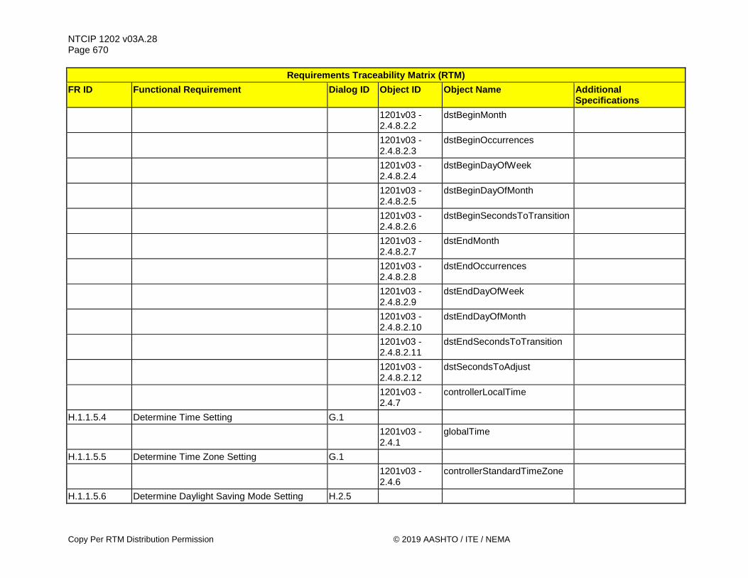
NTCIP 1202 v03A.28 Page 670
Copy Per RTM Distribution Permission © 2019 AASHTO / ITE / NEMA
Requirements Traceability Matrix (RTM) FR ID Functional Requirement Dialog ID Object ID Object Name Additional
Specifications
1201v03 - 2.4.8.2.2
dstBeginMonth
1201v03 - 2.4.8.2.3
dstBeginOccurrences
1201v03 - 2.4.8.2.4
dstBeginDayOfWeek
1201v03 - 2.4.8.2.5
dstBeginDayOfMonth
1201v03 - 2.4.8.2.6
dstBeginSecondsToTransition
1201v03 - 2.4.8.2.7
dstEndMonth
1201v03 - 2.4.8.2.8
dstEndOccurrences
1201v03 - 2.4.8.2.9
dstEndDayOfWeek
1201v03 - 2.4.8.2.10
dstEndDayOfMonth
1201v03 - 2.4.8.2.11
dstEndSecondsToTransition
1201v03 - 2.4.8.2.12
dstSecondsToAdjust
1201v03 - 2.4.7
controllerLocalTime
H.1.1.5.4 Determine Time Setting G.1
1201v03 - 2.4.1
globalTime
H.1.1.5.5 Determine Time Zone Setting G.1
1201v03 - 2.4.6
controllerStandardTimeZone
H.1.1.5.6 Determine Daylight Saving Mode Setting H.2.5
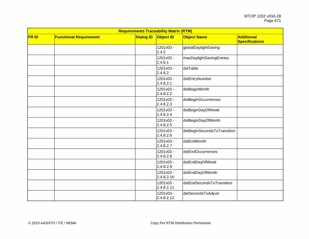
NTCIP 1202 v03A.28 Page 671
© 2019 AASHTO / ITE / NEMA Copy Per RTM Distribution Permission
Requirements Traceability Matrix (RTM) FR ID Functional Requirement Dialog ID Object ID Object Name Additional
Specifications
1201v03 - 2.4.2
globalDaylightSaving
1201v03 - 2.4.8.1
maxDaylightSavingEntries
1201v03 - 2.4.8.2
dstTable
1201v03 - 2.4.8.2.1
dstEntryNumber
1201v03 - 2.4.8.2.2
dstBeginMonth
1201v03 - 2.4.8.2.3
dstBeginOccurrences
1201v03 - 2.4.8.2.4
dstBeginDayOfWeek
1201v03 - 2.4.8.2.5
dstBeginDayOfMonth
1201v03 - 2.4.8.2.6
dstBeginSecondsToTransition
1201v03 - 2.4.8.2.7
dstEndMonth
1201v03 - 2.4.8.2.8
dstEndOccurrences
1201v03 - 2.4.8.2.9
dstEndDayOfWeek
1201v03 - 2.4.8.2.10
dstEndDayOfMonth
1201v03 - 2.4.8.2.11
dstEndSecondsToTransition
1201v03 - 2.4.8.2.12
dstSecondsToAdjust

NTCIP 1202 v03A.28 Page 672
Copy Per RTM Distribution Permission © 2019 AASHTO / ITE / NEMA
Requirements Traceability Matrix (RTM) FR ID Functional Requirement Dialog ID Object ID Object Name Additional
Specifications
1201v03 - 2.4.7
controllerLocalTime
H.1.1.5.7 Monitor Current Time G.1
1201v03 - 2.4.7
controllerLocalTime
1201v03 - 2.4.6
controllerStandardTimeZone
H.1.1.6 Managing Auxiliary Ports Requirements H.1.1.6.1 Determine External Port Information H.2.5
1201v03 - 2.9.1
maxAuxIOv2TableNumDigitalPorts
1201v03 - 2.9.2
maxAuxIOv2TableNumAnalogPorts
1201v03 - 2.9.3
auxIOv2Table
1201v03 - 2.9.3.1
auxIOv2PortType
1201v03 - 2.9.3.2
auxIOv2PortNumber
1201v03 - 2.9.3.3
auxIOv2PortDescription
1201v03 - 2.9.3.4
auxIOv2PortResolution
1201v03 - 2.9.3.6
auxIOv2PortDirection
H.1.1.6.2 Configure Port Information H.2.7
1201v03 - 2.9.3
auxIOv2Table
1201v03 - 2.9.3.1
auxIOv2PortType

NTCIP 1202 v03A.28 Page 673
© 2019 AASHTO / ITE / NEMA Copy Per RTM Distribution Permission
Requirements Traceability Matrix (RTM) FR ID Functional Requirement Dialog ID Object ID Object Name Additional
Specifications
1201v03 - 2.9.3.2
auxIOv2PortNumber
1201v03 - 2.9.3.3
auxIOv2PortDescription
H.1.1.6.3 Required Number of Auxiliary Ports G.1
1201v03 - 2.9.1
maxAuxIOv2TableNumDigitalPorts
1201v03 - 2.9.2
maxAuxIOv2TableNumAnalogPorts
H.1.1.7 Manage Generic Scheduler Requirements
H.1.1.7.1 Configure Timebased Scheduler Month-Day-Date H.2.7
1201v03 - 2.4.3.2.1
timeBaseScheduleNumber
1201v03 - 2.4.3.2.2
timeBaseScheduleMont
1201v03 - 2.4.3.2.3
timeBaseScheduleDay
1201v03 - 2.4.3.2.4
timeBaseScheduleDate
1201v03 - 2.4.3.2.5
timeBaseScheduleDayPlan
H.1.1.7.2 Configure Timebased Scheduler Day Plans and Timebased Actions H.2.7
1201v03 - 2.4.4.3.1
dayPlanNumber
1201v03 - 2.4.4.3.2
dayPlanEventNumber
1201v03 - 2.4.4.3.3
dayPlanHour
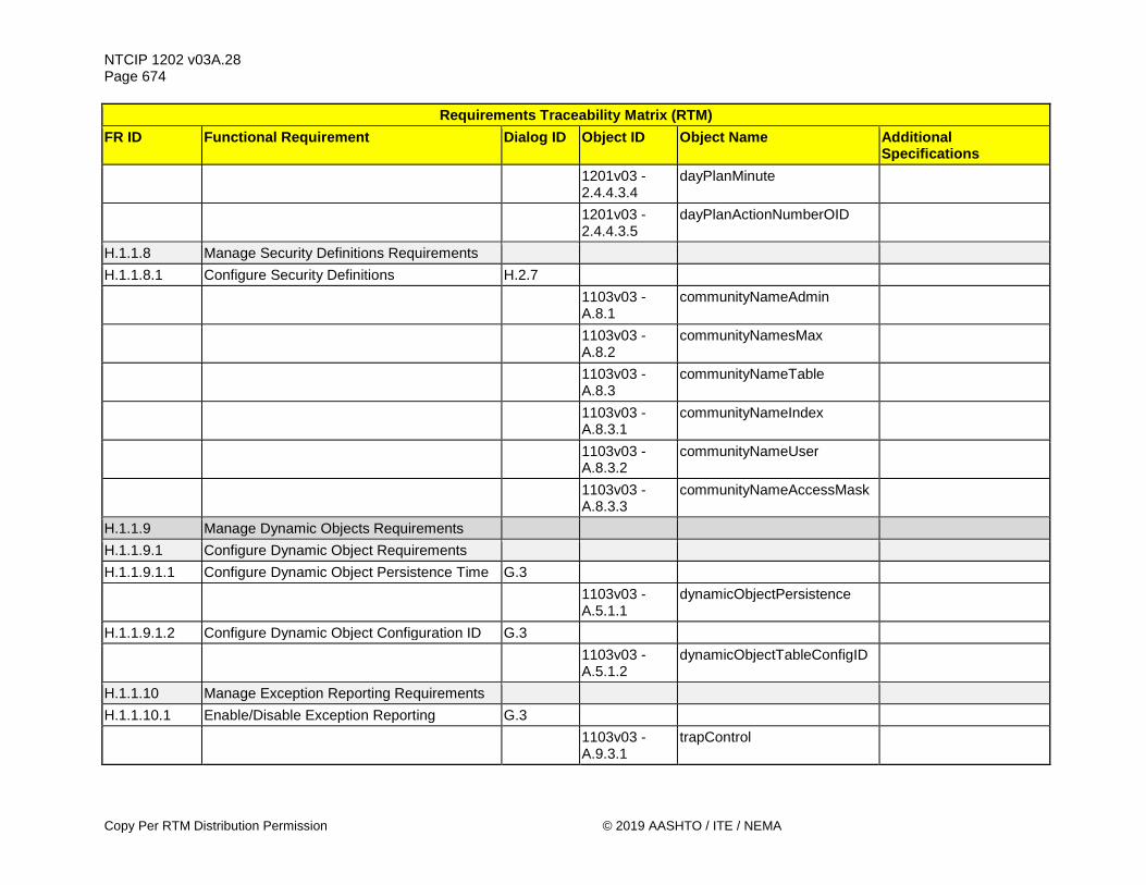
NTCIP 1202 v03A.28 Page 674
Copy Per RTM Distribution Permission © 2019 AASHTO / ITE / NEMA
Requirements Traceability Matrix (RTM) FR ID Functional Requirement Dialog ID Object ID Object Name Additional
Specifications
1201v03 - 2.4.4.3.4
dayPlanMinute
1201v03 - 2.4.4.3.5
dayPlanActionNumberOID
H.1.1.8 Manage Security Definitions Requirements H.1.1.8.1 Configure Security Definitions H.2.7
1103v03 - A.8.1
communityNameAdmin
1103v03 - A.8.2
communityNamesMax
1103v03 - A.8.3
communityNameTable
1103v03 - A.8.3.1
communityNameIndex
1103v03 - A.8.3.2
communityNameUser
1103v03 - A.8.3.3
communityNameAccessMask
H.1.1.9 Manage Dynamic Objects Requirements H.1.1.9.1 Configure Dynamic Object Requirements H.1.1.9.1.1 Configure Dynamic Object Persistence Time G.3
1103v03 - A.5.1.1
dynamicObjectPersistence
H.1.1.9.1.2 Configure Dynamic Object Configuration ID G.3
1103v03 - A.5.1.2
dynamicObjectTableConfigID
H.1.1.10 Manage Exception Reporting Requirements H.1.1.10.1 Enable/Disable Exception Reporting G.3
1103v03 - A.9.3.1
trapControl

NTCIP 1202 v03A.28 Page 675
© 2019 AASHTO / ITE / NEMA Copy Per RTM Distribution Permission
Requirements Traceability Matrix (RTM) FR ID Functional Requirement Dialog ID Object ID Object Name Additional
Specifications
H.1.1.10.2 Configure Exception Reporting Condition Requirements
H.1.1.10.2.1 Configure a Monitored (Watch) Object H.2.7
1103v03 - A.7.5
eventLogConfigTable
1103v03 - A.7.5.1
eventConfigID
1103v03 - A.7.5.2
eventConfigClass
1103v03 - A.7.5.3
eventConfigMode
1103v03 - A.7.5.4
eventConfigCompareValue
1103v03 - A.7.5.5
eventConfigCompareValue2
1103v03 - A.7.5.6
eventConfigCompareOID
1103v03 - A.7.5.7
eventConfigLogOID
1103v03 - A.7.5.8
eventConfigAction
1103v03 - A.9.1.3
watchObjectDefinitionTable
1103v03 - A.9.1.3.1
watchID
1103v03 - A.9.1.3.2
watchStatus
1103v03 - A.9.1.3.3
watchBlock
1103v03 - A.9.1.3.4
watchOID

NTCIP 1202 v03A.28 Page 676
Copy Per RTM Distribution Permission © 2019 AASHTO / ITE / NEMA
Requirements Traceability Matrix (RTM) FR ID Functional Requirement Dialog ID Object ID Object Name Additional
Specifications
H.1.1.10.2.2 Configure a Monitored Group of Objects (Watch Block) H.2.7
1103v03 - A.7.5
eventLogConfigTable
1103v03 - A.7.5.1
eventConfigID
1103v03 - A.7.5.2
eventConfigClass
1103v03 - A.7.5.3
eventConfigMode
1103v03 - A.7.5.4
eventConfigCompareValue
1103v03 - A.7.5.5
eventConfigCompareValue2
1103v03 - A.7.5.6
eventConfigCompareOID
1103v03 - A.7.5.7
eventConfigLogOID
1103v03 - A.7.5.8
eventConfigAction
1103v03 - A.9.1.4
watchBlockTable
1103v03 - A.9.1.4.1
watchBlockNumber
1103v03 - A.9.1.4.2
watchBlockStatus
1103v03 - A.9.1.4.3
watchBlockDescription
1103v03 - A.9.1.4.4
watchBlockValue
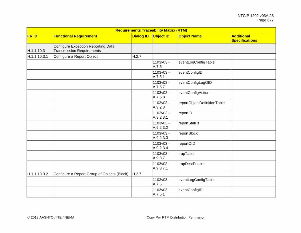
NTCIP 1202 v03A.28 Page 677
© 2019 AASHTO / ITE / NEMA Copy Per RTM Distribution Permission
Requirements Traceability Matrix (RTM) FR ID Functional Requirement Dialog ID Object ID Object Name Additional
Specifications
H.1.1.10.3 Configure Exception Reporting Data Transmission Requirements
H.1.1.10.3.1 Configure a Report Object H.2.7
1103v03 - A.7.5
eventLogConfigTable
1103v03 - A.7.5.1
eventConfigID
1103v03 - A.7.5.7
eventConfigLogOID
1103v03 - A.7.5.8
eventConfigAction
1103v03 - A.9.2.3
reportObjectDefinitionTable
1103v03 - A.9.2.3.1
reportID
1103v03 - A.9.2.3.2
reportStatus
1103v03 - A.9.2.3.3
reportBlock
1103v03 - A.9.2.3.4
reportOID
1103v03 - A.9.3.7
trapTable
1103v03 - A.9.3.7.1
trapDestEnable
H.1.1.10.3.2 Configure a Report Group of Objects (Block) H.2.7
1103v03 - A.7.5
eventLogConfigTable
1103v03 - A.7.5.1
eventConfigID

NTCIP 1202 v03A.28 Page 678
Copy Per RTM Distribution Permission © 2019 AASHTO / ITE / NEMA
Requirements Traceability Matrix (RTM) FR ID Functional Requirement Dialog ID Object ID Object Name Additional
Specifications
1103v03 - A.7.5.7
eventConfigLogOID
1103v03 - A.7.5.8
eventConfigAction
1103v03 - A.9.2.4
reportBlockTable
1103v03 - A.9.2.4.1
reportBlockNumber
1103v03 - A.9.2.4.2
reportBlockStatus
1103v03 - A.9.2.4.3
reportBlockDescription
1103v03 - A.9.2.4.4
reportBlockValue
H.1.1.10.4 Configure Exception Reporting Destination H.2.7
1103v03 - A.6.2
logicalNameTranslationTable
1103v03 - A.6.2.1
logicalNameTranslationIndex
1103v03 - A.6.2.2
logicalNameTranslationLogicalName
1103v03 - A.6.2.3
logicalNameTranslationNetworkAddress
1103v03 - A.6.2.4
logicalNameTranslationStatus
1103v03 - A.7.5.1
eventConfigID
1103v03 - A.9.3.6
trapMgmtTable
1103v03 - A.9.3.6.1
trapMgmtManagerIndex

NTCIP 1202 v03A.28 Page 679
© 2019 AASHTO / ITE / NEMA Copy Per RTM Distribution Permission
Requirements Traceability Matrix (RTM) FR ID Functional Requirement Dialog ID Object ID Object Name Additional
Specifications
1103v03 - A.9.3.6.2
trapMgmtManagerPointer
1103v03 - A.9.3.7
trapTable
1103v03 - A.9.3.7.1
trapDestEnable
H.1.1.10.5 Configure Exception Reporting Community H.2.7
1103v03 - A.8.3
communityNameTable
1103v03 - A.8.3.1
communityNameIndex
1103v03 - A.8.3.2
communityNameUser
1103v03 - A.8.3.3
communityNameAccessMask
1103v03 - A.9.3.6
trapMgmtTable
1103v03 - A.9.3.6.1
trapMgmtManagerIndex
1103v03 - A.9.3.6.3
trapMgmtCommunityNamePointer
H.1.1.10.6 Configure Exception Reporting Operational Mode Requirements
H.1.1.10.6.1 Configure Exception Reporting Acknowledgement H.2.7
1103v03 - A.7.5.1
eventConfigID
1103v03 - A.9.3.6
trapMgmtTable
1103v03 - A.9.3.6.1
trapMgmtManagerIndex

NTCIP 1202 v03A.28 Page 680
Copy Per RTM Distribution Permission © 2019 AASHTO / ITE / NEMA
Requirements Traceability Matrix (RTM) FR ID Functional Requirement Dialog ID Object ID Object Name Additional
Specifications
1103v03 - A.9.3.6.7
trapMgmtMaxRetries
1103v03 - A.9.3.6.8
trapMgmtRepeatInterval
1103v03 - A.9.3.6.9
trapMgmtDelta
1103v03 - A.9.3.7
trapTable
1103v03 - A.9.3.7.2
trapMode
H.1.1.10.6.2 Configure Exception Reporting Aggregation H.2.7
1103v03 - A.9.3.7
trapTable
1103v03 - A.9.3.7.2
trapMode
1103v03 - A.9.3.7.3
trapAggregationTime
1103v03 - A.9.3.6
trapMgmtTable
1103v03 - A.9.3.6.1
trapMgmtManagerIndex
1103v03 - A.9.3.6.7
trapMgmtMaxRetries
1103v03 - A.9.3.6.8
trapMgmtRepeatInterval
1103v03 - A.9.3.6.9
trapMgmtDelta
H.1.1.10.6.3 Configure Exception Reporting Queue H.2.7
1103v03 - A.9.3.7
trapTable
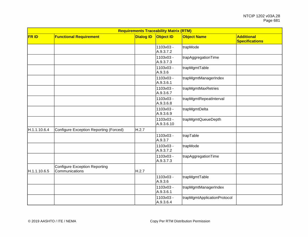
NTCIP 1202 v03A.28 Page 681
© 2019 AASHTO / ITE / NEMA Copy Per RTM Distribution Permission
Requirements Traceability Matrix (RTM) FR ID Functional Requirement Dialog ID Object ID Object Name Additional
Specifications
1103v03 - A.9.3.7.2
trapMode
1103v03 - A.9.3.7.3
trapAggregationTime
1103v03 - A.9.3.6
trapMgmtTable
1103v03 - A.9.3.6.1
trapMgmtManagerIndex
1103v03 - A.9.3.6.7
trapMgmtMaxRetries
1103v03 - A.9.3.6.8
trapMgmtRepeatInterval
1103v03 - A.9.3.6.9
trapMgmtDelta
1103v03 - A.9.3.6.10
trapMgmtQueueDepth
H.1.1.10.6.4 Configure Exception Reporting (Forced) H.2.7
1103v03 - A.9.3.7
trapTable
1103v03 - A.9.3.7.2
trapMode
1103v03 - A.9.3.7.3
trapAggregationTime
H.1.1.10.6.5 Configure Exception Reporting Communications H.2.7
1103v03 - A.9.3.6
trapMgmtTable
1103v03 - A.9.3.6.1
trapMgmtManagerIndex
1103v03 - A.9.3.6.4
trapMgmtApplicationProtocol

NTCIP 1202 v03A.28 Page 682
Copy Per RTM Distribution Permission © 2019 AASHTO / ITE / NEMA
Requirements Traceability Matrix (RTM) FR ID Functional Requirement Dialog ID Object ID Object Name Additional
Specifications
1103v03 - A.9.3.6.5
trapMgmtTransportProtocol
1103v03 - A.9.3.6.6
trapMgmtPortNum
H.1.1.10.6.6 Configure Exception Reporting - Maximum Rate H.2.7
1103v03 - A.9.3.6
trapMgmtTable
1103v03 - A.9.3.6.1
trapMgmtManagerIndex
1103v03 - A.9.3.6.12
trapMgmtAntiStreamRate
H.1.1.10.7 Determine Watch Block Capabilities G.1
1103v03 - A.7.4
maxEventLogConfigs
1103v03 - A.9.1.1
maxWatchObjects
1103v03 - A.9.1.2
maxWatchBlocks
H.1.1.10.8 Determine Report Block Capabilities G.1
1103v03 - A.9.2.1
maxReportObjects
1103v03 - A.9.2.2
maxReportBlocks
H.1.1.10.9 Determine Exception Reporting Trap Channel Capabilities G.1
1103v03 - A.9.3.3
trapMgmtMaxEntries
H.1.1.10.10 Determine Exception Reporting Aggregation Capabilities G.1
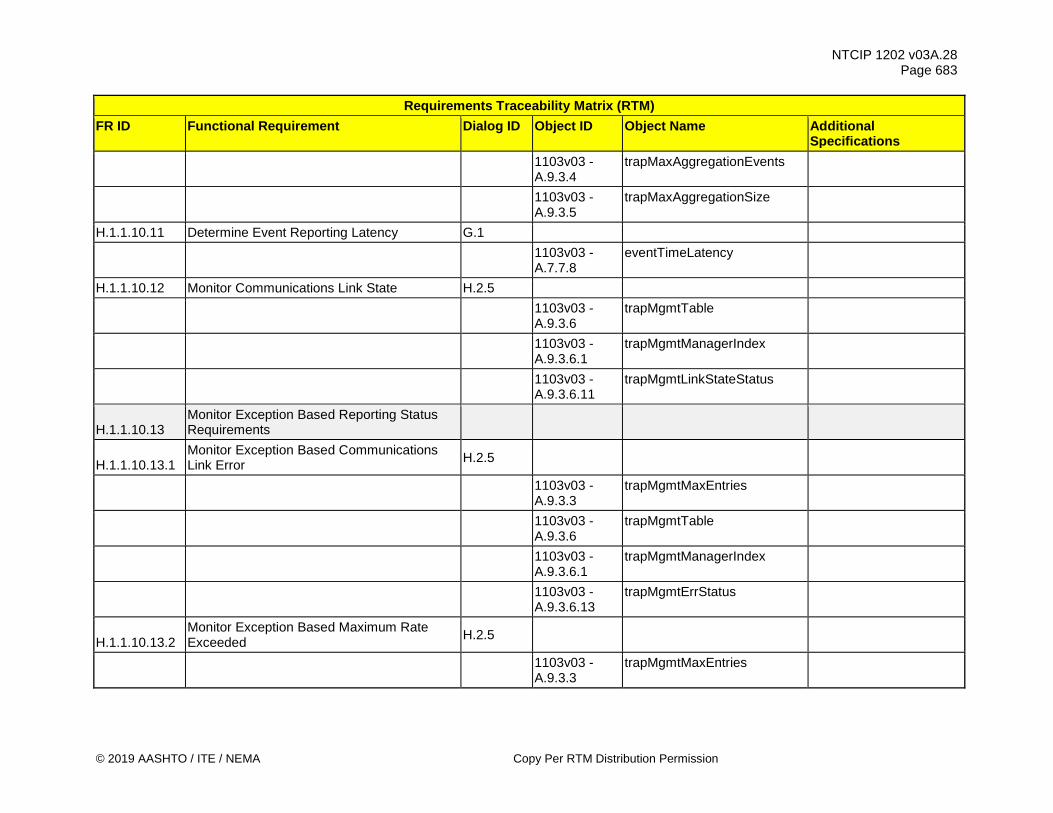
NTCIP 1202 v03A.28 Page 683
© 2019 AASHTO / ITE / NEMA Copy Per RTM Distribution Permission
Requirements Traceability Matrix (RTM) FR ID Functional Requirement Dialog ID Object ID Object Name Additional
Specifications
1103v03 - A.9.3.4
trapMaxAggregationEvents
1103v03 - A.9.3.5
trapMaxAggregationSize
H.1.1.10.11 Determine Event Reporting Latency G.1
1103v03 - A.7.7.8
eventTimeLatency
H.1.1.10.12 Monitor Communications Link State H.2.5
1103v03 - A.9.3.6
trapMgmtTable
1103v03 - A.9.3.6.1
trapMgmtManagerIndex
1103v03 - A.9.3.6.11
trapMgmtLinkStateStatus
H.1.1.10.13 Monitor Exception Based Reporting Status Requirements
H.1.1.10.13.1 Monitor Exception Based Communications Link Error H.2.5
1103v03 - A.9.3.3
trapMgmtMaxEntries
1103v03 - A.9.3.6
trapMgmtTable
1103v03 - A.9.3.6.1
trapMgmtManagerIndex
1103v03 - A.9.3.6.13
trapMgmtErrStatus
H.1.1.10.13.2 Monitor Exception Based Maximum Rate Exceeded H.2.5
1103v03 - A.9.3.3
trapMgmtMaxEntries

NTCIP 1202 v03A.28 Page 684
Copy Per RTM Distribution Permission © 2019 AASHTO / ITE / NEMA
Requirements Traceability Matrix (RTM) FR ID Functional Requirement Dialog ID Object ID Object Name Additional
Specifications
1103v03 - A.9.3.6
trapMgmtTable
1103v03 - A.9.3.6.1
trapMgmtManagerIndex
1103v03 - A.9.3.6.13
trapMgmtErrStatus
H.1.1.10.13.3 Monitor Exception Based Queue Full Error H.2.5
1103v03 - A.9.3.3
trapMgmtMaxEntries
1103v03 - A.9.3.6
trapMgmtTable
1103v03 - A.9.3.6.1
trapMgmtManagerIndex
1103v03 - A.9.3.6.13
trapMgmtErrStatus
H.1.1.10.14 Monitor Exception Based Transmissions H.2.5
1103v03 - A.9.3.3
trapMgmtMaxEntries
1103v03 - A.9.3.6
trapMgmtTable
1103v03 - A.9.3.6.1
trapMgmtManagerIndex
1103v03 - A.9.3.6.16
trapMgmtSeqNum
H.1.1.10.15 Monitor Number of Lost Queued Exception Based Reports H.2.5
1103v03 - A.9.3.3
trapMgmtMaxEntries
1103v03 - A.9.3.6
trapMgmtTable

NTCIP 1202 v03A.28 Page 685
© 2019 AASHTO / ITE / NEMA Copy Per RTM Distribution Permission
Requirements Traceability Matrix (RTM) FR ID Functional Requirement Dialog ID Object ID Object Name Additional
Specifications
1103v03 - A.9.3.6.1
trapMgmtManagerIndex
1103v03 - A.9.3.6.14
trapMgmtLostTraps
H.1.1.10.16 Monitor Number of Exception Based Events H.2.5
1103v03 - A.7.5.1
eventConfigID
1103v03 - A.9.3.3
trapMgmtMaxEntries
1103v03 - A.9.3.6
trapMgmtTable
1103v03 - A.9.3.6.1
trapMgmtManagerIndex
1103v03 - A.9.3.7
trapTable
1103v03 - A.9.3.7.4
trapCounter
H.1.1.10.17 Monitor Exception Based Data G.3
1103v03 - A.9.3.2
trapData
1103v03 - A.9.4.1
trapEvent
H.1.1.10.18 Clear Event Class G.3
1103v03 - A.9.5.1
eventClearClasses
H.1.1.10.19 Clear Event Configuration G.3
1103v03 - A.9.5.2
eventClearConfiguration
H.1.1.10.20 Clear Event Log Table G.3
1103v03 - A.9.5.3
eventClearLog

NTCIP 1202 v03A.28 Page 686
Copy Per RTM Distribution Permission © 2019 AASHTO / ITE / NEMA
Requirements Traceability Matrix (RTM) FR ID Functional Requirement Dialog ID Object ID Object Name Additional
Specifications H.1.1.10.21 Clear Report Objects G.3
1103v03 - A.9.5.4
clearReportObjects
H.1.1.10.22 Clear Report Blocks G.3
1103v03 - A.9.5.5
clearReportBlockTable
H.1.1.10.23 Clear Watch Objects G.3
1103v03 - A.9.5.6
clearWatchObjects
H.1.1.10.24 Clear Watch Blocks G.3
1103v03 - A.9.5.7
clearWatchBlockTable
H.1.1.10.25 Clear Exception Based Reporting Tables G.3
1103v03 - A.9.5.8
clearTrapMgmtTable
H.1.1.10.26 Reset a Communications Link H.2.7
1103v03 - A.9.3.6
trapMgmtTable
1103v03 - A.9.3.6.1
trapMgmtManagerIndex
1103v03 - A.9.3.6.17
trapMgmtSeqNumAck
H.1.2 Generic Status Monitoring Requirements H.1.2.1 Monitor Status of External Device H.2.5
1201v03 - 2.9.1
maxAuxIOv2TableNumDigitalPorts
1201v03 - 2.9.2
maxAuxIOv2TableNumAnalogPorts
1201v03 - 2.9.3
auxIOv2Table

NTCIP 1202 v03A.28 Page 687
© 2019 AASHTO / ITE / NEMA Copy Per RTM Distribution Permission
Requirements Traceability Matrix (RTM) FR ID Functional Requirement Dialog ID Object ID Object Name Additional
Specifications
1201v03 - 2.9.3.1
auxIOv2PortType
1201v03 - 2.9.3.2
auxIOv2PortNumber
1201v03 - 2.9.3.5
auxIOv2PortValue
1201v03 - 2.9.3.7
auxIOv2PortLastCommandedState
H.1.2.2 Retrieve Database Management Requirements
H.1.2.2.1 Monitor Database Operation G.1
1201v03 - 2.3.1
dbCreateTransaction
H.1.2.2.2 Monitor Database Operation Status G.1
1201v03 - 2.3.6
dbVerifyStatus
H.1.2.2.3 Monitor Database Operation Error Status G.1
1201v03 - 2.3.7
dbVerifyError
H.1.2.3 Retrieve Generic Scheduler Settings Requirements
H.1.2.3.1 Monitor Timebased Scheduler Month-Day-Date H.2.5
1201v03 - 2.4.3.1
maxTimeBaseScheduleEntries
1201v03 - 2.4.3.2.1
timeBaseScheduleNumber
1201v03 - 2.4.3.2.2
timeBaseScheduleMont
1201v03 - 2.4.3.2.3
timeBaseScheduleDay

NTCIP 1202 v03A.28 Page 688
Copy Per RTM Distribution Permission © 2019 AASHTO / ITE / NEMA
Requirements Traceability Matrix (RTM) FR ID Functional Requirement Dialog ID Object ID Object Name Additional
Specifications
1201v03 - 2.4.3.2.4
timeBaseScheduleDate
1201v03 - 2.4.3.2.5
timeBaseScheduleDayPlan
H.1.2.3.2 Monitor Timebased Scheduler Day Plans and Timebased Actions H.2.7
1201v03 - 2.4.4.3.1
dayPlanNumber
1201v03 - 2.4.4.3.2
dayPlanEventNumber
1201v03 - 2.4.4.3.3
dayPlanHour
1201v03 - 2.4.4.3.4
dayPlanMinute
1201v03 - 2.4.4.3.5
dayPlanActionNumberOID
H.1.2.3.3 Monitor Active Timebased Schedule H.2.6
1201v03 - 2.4.3.2.1
timeBaseScheduleNumber
1201v03 - 2.4.3.2.2
timeBaseScheduleMonth
1201v03 - 2.4.3.2.3
timeBaseScheduleDay
1201v03 - 2.4.3.2.4
timeBaseScheduleDate
1201v03 - 2.4.3.2.5
timeBaseScheduleDayPlan
H.1.2.3.4 Monitor Active Timebased Schedule Day Plan and Timebased Actions H.2.6
1201v03 - 2.4.4.3.1
dayPlanNumber

NTCIP 1202 v03A.28 Page 689
© 2019 AASHTO / ITE / NEMA Copy Per RTM Distribution Permission
Requirements Traceability Matrix (RTM) FR ID Functional Requirement Dialog ID Object ID Object Name Additional
Specifications
1201v03 - 2.4.4.3.2
dayPlanEventNumber
1201v03 - 2.4.4.3.3
dayPlanHour
1201v03 - 2.4.4.3.4
dayPlanMinute
1201v03 - 2.4.4.3.5
dayPlanActionNumberOID
H.1.2.4 Retrieve Security Definitions Requirements H.1.2.4.1 Determine Security Definitions H.2.7
1103v03 - A.8.1
communityNameAdmin
1103v03 - A.8.2
communityNamesMax
1103v03 - A.8.3
communityNameTable
1103v03 - A.8.3.1
communityNameIndex
1103v03 - A.8.3.2
communityNameUser
1103v03 - A.8.3.3
communityNameAccessMask
H.1.2.5 Retrieve Dynamic Objects Requirements H.1.2.5.1 Determine Dynamic Objects Requirements H.1.2.5.1.1 Determine Dynamic Object Persistence Time G.1
1103v03 - A.5.1.1
dynamicObjectPersistence
H.1.2.5.1.2 Determine Dynamic Object Configuration ID G.1
1103v03 - A.5.1.2
dynamicObjectTableConfigID

NTCIP 1202 v03A.28 Page 690
Copy Per RTM Distribution Permission © 2019 AASHTO / ITE / NEMA
Requirements Traceability Matrix (RTM) FR ID Functional Requirement Dialog ID Object ID Object Name Additional
Specifications
H.1.2.5.2 Monitor STMP-related Communications Requirements
H.1.2.5.2.1 Monitor STMP Data Exchange Requirements
H.1.2.5.2.1.1 Monitor Incoming and Outgoing STMP Packet Exchanges G.1
1103v03 - A.4.1.1
stmpInPkts
1103v03 - A.4.1.2
stmpOutPkts
H.1.2.5.2.1.2 Monitor Incoming and Outgoing STMP Packet Types G.1
1103v03 - A.4.1.15
stmpInGetRequests
1103v03 - A.4.1.16
stmpInGetNexts
1103v03 - A.4.1.17
stmpInSetRequests
1103v03 - A.4.1.18
stmpInGetResponses
1103v03 - A.4.1.25
stmpOutGetRequests
1103v03 - A.4.1.26
stmpOutGetNexts
1103v03 - A.4.1.27
stmpOutSetRequests
1103v03 - A.4.1.28
stmpOutGetResponses
1103v03 - A.4.1.31
stmpInSetRequestsNoReply
1103v03 - A.4.1.32
stmpInSetResponses

NTCIP 1202 v03A.28 Page 691
© 2019 AASHTO / ITE / NEMA Copy Per RTM Distribution Permission
Requirements Traceability Matrix (RTM) FR ID Functional Requirement Dialog ID Object ID Object Name Additional
Specifications
1103v03 - A.4.1.33
stmpInErrorResponses
1103v03 - A.4.1.34
stmpOutSetRequestsNoReply
1103v03 - A.4.1.35
stmpOutSetResponses
1103v03 - A.4.1.36
stmpOutErrorResponses
H.1.2.5.2.2 Monitor STMP Data Exchange Error Requirements
H.1.2.5.2.2.1 Monitor Incoming and Outgoing STMP Error Exchanges - Too Big Error G.1
1103v03 - A.4.1.8
stmpInTooBigs
1103v03 - A.4.1.20
stmpOutTooBigs
H.1.2.5.2.2.2 Monitor Incoming and Outgoing STMP Error Exchanges - No Such Name G.1
1103v03 - A.4.1.9
stmpInNoSuchNames
1103v03 - A.4.1.21
stmpOutNoSuchNames
H.1.2.5.2.2.3 Monitor Incoming and Outgoing STMP Error Exchanges - Bad Value G.1
1103v03 - A.4.1.10
stmpInBadValues
1103v03 - A.4.1.22
stmpOutBadValues
H.1.2.5.2.2.4 Monitor Incoming and Outgoing STMP Error Exchanges - Read-Only G.1

NTCIP 1202 v03A.28 Page 692
Copy Per RTM Distribution Permission © 2019 AASHTO / ITE / NEMA
Requirements Traceability Matrix (RTM) FR ID Functional Requirement Dialog ID Object ID Object Name Additional
Specifications
1103v03 - A.4.1.11
stmpInReadOnlys
1103v03 - A.4.1.23
stmpOutReadOnly
H.1.2.5.2.2.5 Monitor Incoming and Outgoing STMP Error Exchanges - General Error G.1
1103v03 - A.4.1.12
stmpInGenErrs
1103v03 - A.4.1.24
stmpOutGenError
1103v03 - A.4.1.31
stmpInSetRequestsNoReply
1103v03 - A.4.1.32
stmpInSetResponses
1103v03 - A.4.1.33
stmpInErrorResponses
1103v03 - A.4.1.34
stmpOutSetRequestsNoReply
1103v03 - A.4.1.35
stmpOutSetResponses
1103v03 - A.4.1.36
stmpOutErrorResponses
H.1.3 Generic Data Retrieval Requirements H.1.3.1 Support Logged Data
H.1.3.1.1 Retrieve Current Configuration of Logging Service H.2.1.1
1103v03 - A.7.3.1
eventClassNumber
1103v03 - A.7.3.2
eventClassLimit
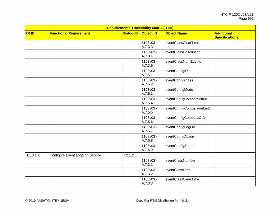
NTCIP 1202 v03A.28 Page 693
© 2019 AASHTO / ITE / NEMA Copy Per RTM Distribution Permission
Requirements Traceability Matrix (RTM) FR ID Functional Requirement Dialog ID Object ID Object Name Additional
Specifications
1103v03 - A.7.3.3
eventClassClearTime
1103v03 - A.7.3.4
eventClassDescription
1103v03 - A.7.3.6
eventClassNumEvents
1103v03 - A.7.5.1
eventConfigID
1103v03 - A.7.5.2
eventConfigClass
1103v03 - A.7.5.3
eventConfigMode
1103v03 - A.7.5.4
eventConfigCompareValue
1103v03 - A.7.5.5
eventConfigCompareValue2
1103v03 - A.7.5.6
eventConfigCompareOID
1103v03 - A.7.5.7
eventConfigLogOID
1103v03 - A.7.5.8
eventConfigAction
1103v03 - A.7.5.9
eventConfigStatus
H.1.3.1.2 Configure Event Logging Service H.2.1.2
1103v03 - A.7.3.1
eventClassNumber
1103v03 - A.7.3.2
eventClassLimit
1103v03 - A.7.3.3
eventClassClearTime
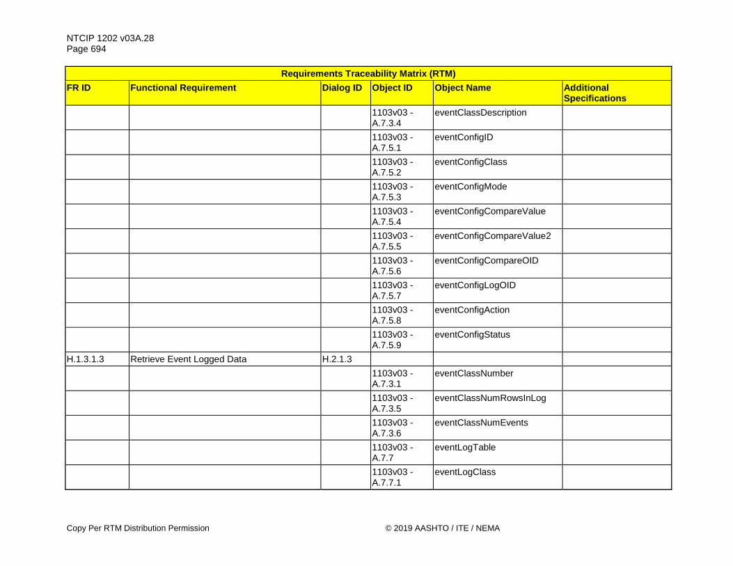
NTCIP 1202 v03A.28 Page 694
Copy Per RTM Distribution Permission © 2019 AASHTO / ITE / NEMA
Requirements Traceability Matrix (RTM) FR ID Functional Requirement Dialog ID Object ID Object Name Additional
Specifications
1103v03 - A.7.3.4
eventClassDescription
1103v03 - A.7.5.1
eventConfigID
1103v03 - A.7.5.2
eventConfigClass
1103v03 - A.7.5.3
eventConfigMode
1103v03 - A.7.5.4
eventConfigCompareValue
1103v03 - A.7.5.5
eventConfigCompareValue2
1103v03 - A.7.5.6
eventConfigCompareOID
1103v03 - A.7.5.7
eventConfigLogOID
1103v03 - A.7.5.8
eventConfigAction
1103v03 - A.7.5.9
eventConfigStatus
H.1.3.1.3 Retrieve Event Logged Data H.2.1.3
1103v03 - A.7.3.1
eventClassNumber
1103v03 - A.7.3.5
eventClassNumRowsInLog
1103v03 - A.7.3.6
eventClassNumEvents
1103v03 - A.7.7
eventLogTable
1103v03 - A.7.7.1
eventLogClass

NTCIP 1202 v03A.28 Page 695
© 2019 AASHTO / ITE / NEMA Copy Per RTM Distribution Permission
Requirements Traceability Matrix (RTM) FR ID Functional Requirement Dialog ID Object ID Object Name Additional
Specifications
1103v03 - A.7.7.2
eventLogNumber
1103v03 - A.7.7.3
eventLogID
1103v03 - A.7.7.4
eventLogTime
1103v03 - A.7.7.5
eventLogValue
1103v03 - A.7.8
numEvents
H.1.3.1.4 Configure Clearing of Event Class Log G.3
1103v03 - A.7.3.1
eventClassNumber
1103v03 - A.7.3.3
eventClassClearTime
H.1.3.1.5 Determine Capabilities of Event Logging Service G.1
1103v03 - A.7.2
maxEventClasses
1103v03 - A.7.4
maxEventLogConfigs
1103v03 - A.7.6
maxEventLogSize
H.1.3.1.6 Determine Number of Logged Events per Event Class G.1
1103v03 - A.7.3.1
eventClassNumber
1103v03 - A.7.3.5
eventClassNumRowsInLog
1103v03 - A.7.3.6
eventClassNumEvents

NTCIP 1202 v03A.28 Page 696
Copy Per RTM Distribution Permission © 2019 AASHTO / ITE / NEMA
Requirements Traceability Matrix (RTM) FR ID Functional Requirement Dialog ID Object ID Object Name Additional
Specifications
1103v03 - A.7.8
numEvents
H.1.3.1.7 Support a Number of Events to Store in Log See Requirement
H.1.3.1.7 in PRL H.1.3.1.8 Configure Clearing of Global Log G.3
1103v03 - A.9.5.3
eventClearLog
H.1.3.1.9 Determine Total Number of Logged Events G.1
1103v03 - A.7.3.1
eventClassNumber
1103v03 - A.7.3.5
eventClassNumRowsInLog
1103v03 - A.7.3.6
eventClassNumEvents
1103v03 - A.7.8
numEvents
H.1.3.1.10 Determine Number of Events within a Class G.1
1103v03 - A.7.3.1
eventClassNumber
1103v03 - A.7.3.5
eventClassNumRowsInLog
1103v03 - A.7.3.6
eventClassNumEvents
1103v03 - A.7.8
numEvents
H.1.3.1.11 Determine Event Logging Resolution G.1
1103v03 - A.7.7.6
eventLogTimeMilliseconds
H.1.3.1.12 Clear Event Configuration G.3
1103v03 - A.9.5.2
eventClearConfiguration

NTCIP 1202 v03A.28 Page 697
© 2019 AASHTO / ITE / NEMA Copy Per RTM Distribution Permission
Requirements Traceability Matrix (RTM) FR ID Functional Requirement Dialog ID Object ID Object Name Additional
Specifications H.1.3.1.13 Clear Event Classes G.3
1103v03 - A.9.5.1
eventClearClasses
H.1.3.1.14 Clear Event Class Log G.3
1103v03 - A.7.3.1
eventClassNumber
1103v03 - A.7.3.3
eventClassClearTime
H.1.3.1.15 Retrieve Non-Sequential Clock Changes H.2.1.3 See 4.3.3
1103v03 - A.7.3.1
eventClassNumber
1103v03 - A.7.3.5
eventClassNumRowsInLog
1103v03 - A.7.3.6
eventClassNumEvents
1103v03 - A.7.7
eventLogTable
1103v03 - A.7.7.1
eventLogClass
1103v03 - A.7.7.2
eventLogNumber
1103v03 - A.7.7.3
eventLogID
1103v03 - A.7.7.4
eventLogTime
1103v03 - A.7.7.5
eventLogValue
1103v03 - A.7.8
numEvents
5.4.22.6 unitTimeNonSequentialSource

NTCIP 1202 v03A.28 Page 698
Copy Per RTM Distribution Permission © 2019 AASHTO / ITE / NEMA
Requirements Traceability Matrix (RTM) FR ID Functional Requirement Dialog ID Object ID Object Name Additional
Specifications
5.4.22.7 unitTimeNonSequentialChange
5.4.22.8 unitTimeNonSequentialDelta
H.1.3.2 Supplemental Requirements for Event Monitoring
H.1.3.2.1 Record and Timestamp Events
H.1.3.2.2 Support a Number of Event Classes See Requirement
H.1.3.2.2 in PRL
H.1.3.2.3 Support a Number of Events to Log See Requirement
H.1.3.2.3 in PRL
H.1.3.2.4 Support Monitoring of Event Type Requirements
H.1.3.2.4.1 Support On-Change Events See 1103v03 - A.7.5.3 H.1.3.2.4.2 Support Greater Than Events See 1103v03 - A.7.5.3 H.1.3.2.4.3 Support Less Than Events See 1103v03 - A.7.5.3 H.1.3.2.4.4 Support Hysteresis Events See 1103v03 - A.7.5.3 H.1.3.2.4.5 Support Periodic Events See 1103v03 - A.7.5.3 H.1.3.2.4.6 Support Bit Flag Events See 1103v03 - A.7.5.3 H.1.3.2.4.7 Support Event Monitoring on Any Data H.1.4 Generic Control Requirements H.1.4.1 Control External Device H.2.7
1201v02 - 2.8.3.1
auxIOPortType
1201v02 - 2.8.3.2
auxIOPortNumber
1201v02 - 2.8.3.5
auxIOPortValue
H.1.4.2 Control Database Operation Requirements H.1.4.2.1 Control Database Access G.3

NTCIP 1202 v03A.28 Page 699
© 2019 AASHTO / ITE / NEMA Copy Per RTM Distribution Permission
Requirements Traceability Matrix (RTM) FR ID Functional Requirement Dialog ID Object ID Object Name Additional
Specifications
1201v03 - 2.3.1
dbCreateTransaction
H.1.4.2.2 Perform Database Consistency Check H.2.2
1201v03 - 2.3.1
dbCreateTransaction
1201v03 - 2.3.6
dbVerifyStatus
1201v03 - 2.3.7
dbVerifyError
H.1.4.2.3 Enforce Consistency Check Parameters H.2.2
1201v03 - 2.3.1
dbCreateTransaction
1201v03 - 2.3.6
dbVerifyStatus
1201v03 - 2.3.7
dbVerifyError
H.1.5 Generic Performance Requirements H.1.5.1 Atomic Operations

NTCIP 1202 v03A.28 Page 700
Do Not Copy Without Written Permission © 2019 AASHTO / ITE / NEMA
Annex B Object Tree [Informative]
Figure 10 and Figure 11 provide a pictorial representation of the Actuated Signal Controller Object Tree Structure. The tree structure identifies how the object definitions are combined under specific nodes.
Figure 10 Object Tree for NTCIP 1202 v03 (continued in Figure 11)
asc (1)
phase (1)
maxPhaseGroups (3)
phaseStatusGroupTable (4)
phaseControlGroupTable (5)
maxPhases (1)
phaseTable (2)
timebaseAsc (5)
timebaseAscPatternSync (1)
maxTimebaseAscActions (2)
timebaseAscActionTable (3)
timebaseAscActionStatus (4)
actionPlanControl (5)
coordOperationalMode (1)
coordCorrectionMode (2)
coordMaximumMode (3)
coordForceMode (4)
maxPatterns (5)
patternTableType (6)
patternTable (7) maxSplits (8)
coord (4)
splitTable (9) coordPatternStatus (10)
localFreeStatus (11)
coordCycleStatus (12)
coordSyncStatus (13)
systemPatternControl (14)
systemSyncControl (15)
unitCoordSyncPoint (16)
unitStartUpFlash (1)
unitAutoPedestrianClear (2)
unitBackupTime (3)
unit (3)
unitRedRevert (4)
unitControlStatus (5)
unitFlashStatus (6)
unitAlarmStatus2 (7)
unitAlarmStatus1 (8)
unitControl (10)
maxAlarmGroups (11)
alarmGroupTable (12)
maxSpecialFunctionOutputs (13)
specialFunctionOutputTable (14)
unitMCETimeout (15)
unitMCEIntAdv (16)
ascElevationOffset (17)
unitStartUpFlashMode (18)
unitUserDefinedBackupTime (19)
maxUserDefinedBackupTimeContent (20)
unitUserDefinedBackupTimeContentTable (21)
ascClock (22)
commPorts (23)
maxGlobalSetIds (24)
globalSetIdTable (25)
shortAlarmStatus (9)
unitAlarmStatus3 (26)
unitAlarmStatus4 (27)
unitControl (10)
maxVehicleDetectorStatusGroups (3)
vehicleDetectorStatusGroupTable (4)
volumeOccupancyReport (5)
maxVehicleDetectors (1)
vehicleDetectorTable (2)
maxPedestrianDetectors (6)
pedestrianDetectorTable (7)
detector (2)
maxPedestrianDetectorGroups (8)
pedestrianDetectorStatusGroupTable (9)
pedestrianDetectorReport (10)
maxVehicleDetectorControlGroups (11)
pedestrianDetectorControlGroupTable (12)
preempt (6)
maxPreempts (1)
preemptTable (2)
preemptControlTable (3)
preemptStatus (4)
maxPreemptGroups (5)
preemptStatusGroupTable (6)
preemptQueueDelayTable (7)
maxPreemptGates (8)
preemptGateTable (9)
ring (7)
maxRings (1) maxSequences (2) sequenceTable (3) maxRingControl
Groups (4)ringControlGroup
Table (5) ringStatusTable (6)
channel (8)
maxChannels (1)
channelTable (2)
maxChannelStatusGroups (3)
channelStatusGroupTable (4)
ts2port1 (10)
maxPort1Addresses (1) port1Table (2)
overlap (9)
maxOverlaps (1)
overlapTable (2)
maxOverlapStatusGroups (3)
overlapStatusGroupTable (4)
ascBlock (11)
ascBlockGetControl (1)
ascBlockData (2)
ascBlockErrorStatus (3)

NTCIP 1202 v03A.28 Page 701
© 2019 AASHTO / ITE / NEMA Do Not Copy Without Written Permission
Figure 11 Object Tree for NTCIP 1202 v03 (Continued)
ascIOmapMaxOutputs (3)
ascIOinputMapTable (4)
ascIOinputMapStatusTable (5)
ascIOmapControl (1)
ascIOmapMaxInputs (2)
ascIOmapOutputFunctions (10)
ascIOoutputMapTable (6)
ascIOmapping (13)
ascIOoutputMapStatusTable (7)
ascIOmapFIO (11)
ascIOmapTS1 (12)
ascIOmapInputFunctions (9)
ascIOmapDescriptionTable (8)
ascIOmapBIU (13)
ascIOmapAUX (15)
ascIOmapSIU (14)
maxCabinetEnvironDevices (1)
cabinetEnvironDevicesTable (2)
maxCabinetTempSensors (3)
maxCabinetHumiditySenso
rs (5)cabinetHumiditySensorStatusTable (6)
ascPowerSource (7)
atccLEDMode (9)
cabinetEnvironment (12)
cabinetTempSensorStatusTable (4)
ascLineVolts (8)
siuport1 (14)
maxSIUPort1Addresses (1) siuport1Table (2)
ascRsuPort (15)
rsuCommPort (1)
maxRsuPorts (2) rsuPortTable (3)
ascSpat (16)
spatTimestamp (1)
spatEnabledLanesCommand (2)
spatEnabledLanesConcurrencyTable (3)
spatOptions (4)
spatPortTable (5)
ascCurrentTick(6)
ascCurrentTickMsOffset (7)
rsuAsc (17)
rsuAscSpat (1) ascCvDetector (2)

NTCIP 1202 v03A.28 Page 702
Do Not Copy Without Written Permission © 2019 AASHTO / ITE / NEMA
Annex C Test Procedures [Normative]
It is anticipated that Test Procedures may be developed as part of a future revision of NTCIP 1202 v03. Annex C is a placeholder, at present.

NTCIP 1202 v03A.28 Page 703
© 2019 AASHTO / ITE / NEMA Do Not Copy Without Written Permission
Annex D Documentation of Revisions [Informative]
Annex D identifies the changes that have been made to NTCIP 1202 v03. The NTCIP effort makes reasonable efforts to ensure that standards are as backward compatible as possible, but the primary purpose of NTCIP 1202 v03 is to provide interoperability by developing standards in a consensus environment. When changes are required to meet these objectives, the problematic objects are refined (if the issue is primarily editorial) or deprecated and, in most cases, replaced with new objects. Annex D identifies why each of these changes has been made. New implementations should support the new/replacement objects; they may also support deprecated objects.
D.1 NTCIP 1202 v02 to NTCIP 1202 v03 The following identify changes that were made from NTCIP 1202 v02 to NTCIP 1202 v03.
D.1.1 Added Systems Engineering Process The major change is the structure of the document. NTCIP 1202 v03 adds systems engineering process (SEP) content defined in NTCIP 8002, Annex B1, version 01, which was published on September 2016. The SEP includes the definition of the user needs, functional requirements, dialogs and a requirements traceability matrix in addition to the already existing management information base (MIB). The conformance group definitions and the conformance statement contained in Version 2 of this Standard were replaced by the Protocol Requirements List (Section 3), which allows a user to specify which functions are supposed to be supported by an ASC.
D.1.2 General MIB Changes General edits were made to the MIB header in NTCIP 1202 v03 to reflect updates to other MIBs from which the NTCIP 1202 v03 MIB imports data. All DESCRIPTION fields were updated to conform to NTCIP 8004 v02. Additionally, many DESCRIPTION fields have received additional clarifications and explanations to remove ambiguities. The STATUS of all objects was changed to "mandatory" to reflect that conformance for NTCIP 1202 v03 is now measured through the use of the PRL as contained in Section 3 and the RTM contained in Annex A. References to objects defined in NTCIP 1201 are now made through the RTM rather than through comments in the MIB. Default values (DEFVAL) were added to certain object definitions (e.g., status objects, control objects). Several objects were added to reflect new user needs.
D.1.3 New User Needs In addition to the systems engineering content (user needs, requirements) developed that trace to existing objects in NTCIP 1202 v02, new user needs were defined and supported in NTCIP 1202 v03. From these new user needs, new requirements and design content (in the form of dialogs and object definitions) were developed and included in NTCIP 1202 v03. The following identifies these new user needs supported.

NTCIP 1202 v03A.28 Page 704
Do Not Copy Without Written Permission © 2019 AASHTO / ITE / NEMA
D.1.3.1 Added Support for Connected Vehicle Environment NTCIP 1202 v03 supports a new user need to provide a standardized way to exchange signal phasing and timing data (SPaT), MAP (roadway geometry) data, and the presence of connected devices with a RoadSide Unit (RSU) in a connected vehicle environment. This user need includes support to manage the interface between an ASC and a RSU.
D.1.3.2 Added Support to Manage the Cabinet Environment NTCIP 1202 v03 supports a new user need to provide a standardized way to monitor and manage the operating environment that the ASC is located in. The operating environment includes the temperature and humidity within the ASC cabinet, the status of the cabinet doors (open or closed), and if the cabinet is flooding.
D.1.3.3 Added Support to Manage the Power Sources NTCIP 1202 v03 supports a new user need to provide a standardized way to monitor and manage the power sources for the ASC.
D.1.3.4 Added Support to Retrieve Operational Performance Data NTCIP 1202 v03 supports a new user need to provide a standardized way to manage and retrieve the collection of signal operations and detector data for the analysis of signal timing efficacy. An example of this operational data is the Indiana Traffic Signal Hi Resolution Data Logger Enumerations.
D.1.3.5 Added Support to Manage I/O Mapping NTCIP 1202 v03 supports a new user need to provide a standardized way to manage and retrieve the Input / Output mapping for the ASC. The user need also allows a manager to reset the input/output mapping to a default configuration.
D.1.3.6 Added Support for Accessible Pedestrian Signals (APS) NTCIP 1202 v03 supports a new user need to support the configuration of APS push buttons.
D.1.3.7 Added Support to Activate an Action Plan NTCIP 1202 v03 supports a new user need to provide a standardized way to call a pre-configured action plan. In NTCIP 1202 v02, each action plan defines a group of functions, such as activating an output, that may be activated from a scheduler. NTCIP 1202 v03 extends this feature so the action plan may be manually called outside the scheduler.
D.1.3.8 Added Support to Manually Advance the Controller Remotely NTCIP 1202 v03 supports a new user need to provide a standardized way to remotely and manually advance the ASC through the phase or interval.
D.1.3.9 Added Support for Condition Based Exception Reporting NTCIP 1202 v03 supports a new user need to provide a standardized way to manage exception-based reporting for the ASC. Under this scenario, a manager can configure an ASC to automatically transmit data to a management station when specific conditions are satisfied.
NTCIP 1202 v03A.28 Page 705
© 2019 AASHTO / ITE / NEMA Do Not Copy Without Written Permission
D.1.4 New Requirements In addition to new requirements and objects to support the user needs expressed in Annex D.1.3, new requirements (and objects) were added to extend user needs already supported in NTCIP 1202 v02. The following identifies these new requirements and supported in NTCIP 1202 v03.
D.1.4.1 Manage ASC Location NTCIP 1202 v03 adds requirements to manage the location of the ASC.
D.1.4.2 Manage Communications Ports NTCIP 1202 v03 adds requirements to manage the communications ports on the ASC.
D.1.4.3 Manage ASC Clock NTCIP 1202 v03 adds requirements to manage the clock of an ASC.
D.1.4.4 Manage User-Defined Backup Time NTCIP 1202 v03 adds requirements to configure a user-defined backup time, based on user-defined functions in addition to the existing backup time defined in NTCIP 1202 v02. The backup time defines the period of time to be exceeded when no SET operations are received for a set of system control parameters before the ASC reverts to Backup Mode. The set of system control parameters are defined in NTCIP 1202 v02 for the existing backup time, and is user defined for the user-defined backup time.
D.1.4.5 Support for Advanced Warning Signal Indications NTCIP 1202 v03 adds requirements to support warnings in advanced of a green or red signal indication for a phase.
D.1.4.6 Support for Phase Maximum 3 NTCIP 1202 v03 added requirements to support a Phase Maximum 3 mode, which has a range from 0 to 6000 seconds.
D.1.4.7 Support for Bicycle Phases NTCIP 1202 v03 adds requirements to support bicycle phases for the ASC.
D.1.4.8 Support for Transit Phases NTCIP 1202 v03 adds requirements to support transit phases for the ASC.
D.1.4.9 Manage Alternate Times for Transitions NTCIP 1202 v03 adds requirements to manage alternate minimum times that can be used during transitions.
D.1.4.10 Manage Coordination Point NTCIP 1202 v03 adds requirements to manage the coordination point for the unit and for a specific pattern for the ASC.
NTCIP 1202 v03A.28 Page 706
Do Not Copy Without Written Permission © 2019 AASHTO / ITE / NEMA
D.1.4.11 Support for Additional Overlaps NTCIP 1202 v03 adds support for several additional overlap configurations, including for flashing yellow arrows, flashing red arrows, and transit-specific overlaps.
D.1.4.12 Manage Preempt Exit Strategy NTCIP 1202 v03 adds requirements to manage the exit strategy out of a preempt sequence.
D.1.4.13 Manage Additional Alarms NTCIP 1202 v03 adds requirements to configure and monitor additional alarms for the ASC.
D.1.4.14 Support for Paired Detectors NTCIP 1202 v03 adds requirements to support paired detectors (e.g., speed traps) for the ASC.
D.1.4.15 Improved Support for Vehicle Detectors NTCIP 1202 v03 adds requirements to improve support for vehicle detectors for the ASC. Examples include support to define average vehicle lengths, collect speed data, define detector types, data collection periods up to 3600 seconds, and data collection periods based on the current cycle length (instead of a fixed period).
D.1.4.16 Improved Support for Pedestrian Detectors NTCIP 1202 v03 adds requirements to improve support for detector data for the ASC. Examples include support to reset a pedestrian detector, define a pedestrian pushbutton for accessible pedestrian signal (APS) features, monitor pedestrian detector status, and generate pedestrian detector reports.
D.1.4.17 Block Objects for New NTCIP 1202 v03 Objects NTCIP 1202 v03 adds new block objects to support the new object definitions added in NTCIP 1202 v03.
D.1.5 Changes to Existing Objects In addition new enumerations were added to several existing object definitions in NTCIP 1202 v02. The following identifies the new enumerations supported in NTCIP 1202 v03.
D.1.5.1 Additional Coordination Correction Mode NTCIP 1202 v03 added an enumeration for a subtractOnly mode for the coordCorrectionMode object. This mode support coordination correction by subtracting only from the timings.
NTCIP 1202 v03A.28 Page 707
© 2019 AASHTO / ITE / NEMA Do Not Copy Without Written Permission
Annex E User Requests [Informative]
Annex E identifies features that were suggested for NTCIP 1202 v03, but are either supported by mechanisms that may not be readily obvious, or are not supported by NTCIP 1202 v03.
E.1 Features Not Supported by This Version Features considered for inclusion in NTCIP 1202 v03 but not included are as follows:
E.1.1 Interval Based Controllers The NTCIP ASC Working Group (WG) considered including support for interval-based controllers (See Section 2.3.2) in NTCIP 1202 v03, but due to time and schedule considerations, was deferred to a future version of NTCIP 1202. User needs and requirements were developed for interval-based controllers, and draft design content to fulfill some of the requirements for interval-based controllers were developed but are not included in NTCIP 1202 v03. The developed content has been saved by NTCIP for consideration for future versions of NTCIP 1202.
E.1.2 Non-Persistent Timing Patterns The NTCIP ASC WG considered including support for non-persistent traffic patterns in NTCIP 1202 v03, but due to time and schedule considerations, was deferred to a future version of NTCIP 1202. Non-persistent timing patterns are temporary timing patterns that are not retained in the ASC through a power loss. User needs were developed to support non-persistent traffic patterns but are not included in NTCIP 1202 v03.
E.1.3 Traffic Adaptive Algorithm The NTCIP ASC WG considered including support for traffic adaptive strategies in NTCIP 1202 v03, but due to time and schedule considerations, was deferred to a future version of NTCIP 1202. Traffic adaptive is used to continuously adjust the signal timing pattern (cycle, offset and splits) based on traffic demand as determined by detector inputs and other inputs, such as from an adjacent signalized intersection. User needs and requirements were developed to support traffic adaptive strategies but are not included in NTCIP 1202 v03. The developed content has been saved by NTCIP for consideration for future versions of NTCIP 1202.
E.1.4 Peer-to-Peer The NTCIP ASC WG considered including support for peer-to-peer communications in NTCIP 1202 v03, but due to time and schedule considerations and complexity of the topic, was deferred to a future version of NTCIP 1202. User needs, requirements, and draft design content were developed to support peer-to-peer communications were developed but are not included in NTCIP 1202 v03. The developed content has been saved by NTCIP for consideration for future versions of NTCIP 1202.
E.1.5 Signal Control Priority The NTCIP ASC WG considered including support for signal control priority, including for a connected vehicle environment, in NTCIP 1202 v03, but the ASC WG that the user needs, requirements and design were better handled by the Signal Control and Priority (SCP) WG. During the development phase, the ASC WG identified several new requirements related to signal control priority, especially as it relates to
NTCIP 1202 v03A.28 Page 708
Do Not Copy Without Written Permission © 2019 AASHTO / ITE / NEMA
the connected vehicle environment. New design content was also developed to support most of the new requirements. These new requirements and design content have been saved by NTCIP and provided to the SCP WG for consideration for future versions of NTCIP 1211.
E.1.6 Additional Support for ADA The NTCIP ASC WG considered including support for ADA pedestrians using non-visual formats, such as audible tones, verbal messages, and/or vibrating surfaces, but due to time and schedule considerations, were deferred to a future version of NTCIP 1202. User needs, requirements and draft design content were developed to support non-visual formats, but consensus was not reached on the design content, and there were higher priority user needs. The developed content has been saved by NTCIP for consideration for future versions of NTCIP 1202.
E.1.7 Programmable Logic Gates and Functions The NTCIP ASC WG considered and developed user needs, requirements, and system detailed design (SDD) to support programmable logic functions and gates. However, following the User Comment period, the ASC WG agreed to remove programmable logic functions and gates. While the proposed NTCIP 1202 v03 design incorporated most of the desired functions, custom and unique functions and operations (that were not addressed by the proposed SDD) already exist and are implemented. For that reason, non-NTCIP-standardized objects are still needed and used. In this instance, standardizing programmable logic and gates in NTCIP 1202 v03 offered little benefit to managing this functionality. A Section 3.3.2.1 provision was added to require the provision of a proprietary MIB for ASC devices that wish to claim conformance to NTCIP 1202 v03.
E.1.8 Advanced Preempt Inputs The NTCIP ASC WG considered support for advanced preempt inputs, such as provided by IEEE 1570 was considered, but due to time and schedule considerations and complexity of the topic, was deferred to a future version of NTCIP 1202.
E.1.9 Conflict Monitoring Unit and Channel Support With the advent of more than 16 channels, the NTCIP ASC WG considered adding support to allow mapping of channel outputs to a Conflict Monitoring Unit (CMU) and to allow external devices, such as video detection or audible pedestrian devices, to monitor the CMU for channel status. Thus, the NTCIP ASC WG agreed it did not have sufficient time to properly consider the proper solutions.
E.1.10 Traffic Signal Controller Broadcast Message (TSCBM) NTCIP 1202 v02 did not include an interface between the ASC and the RSU. To support early deployments, a Traffic Signal Controller Broadcast Message (TSCBM) was developed using a Systems Engineering Process (SEP) under USDOT Contract No. DTFH61-06-D-00007 to allow an ASC to provide the signal controller data necessary for an RSU to create and broadcast a SPaT message. During the transitional period while the SPaT design elements (dialogs and data objects) in NTCIP 1202 v03 are being implemented and verified, the TSCBM is allowed as an alternative solution if implemented as follows:
a) The ASC is required to broadcast TSCBM to the RSU using the message structure defined in Table 3-4 of the V2I Hub Interface Control Document (ICD) dated March 2017 (see Section 1.2.2); and
b) The ASC is required to broadcast the TSCBM to the RSU at a rate of once per 100 milliseconds continually without interruption.
The TSCBM is not recommended for new designs.

NTCIP 1202 v03A.28 Page 709
© 2019 AASHTO / ITE / NEMA Do Not Copy Without Written Permission
E.1.11 startTime While developing the support for the connected vehicle environment, the ASC WG intended to support all mandatory and optional elements of the SAE J2735_201603 SPaT message. However, the optional startTime data within the data frame DF_TimeChangeDetails is not supported in NTCIP 1202 v03. The ASC WG reviewed the definition of startTime and was unable to unambiguously determine a use case for and agree on the proper usage and intent of startTime. Also, there was no known implementation of startTime at the time in the United States. Thus, the ASC WG agreed not to include support for startTime in NTCIP 1202 v03.
NTCIP 1202 v03A.28 Page 710
Do Not Copy Without Written Permission © 2019 AASHTO / ITE / NEMA
Annex F Generic Concepts and Definitions
F.1 Meaning of ‘Other’ as a Value To obtain the goals of interoperability and interchangeability among devices complying with NTCIP standards, the standard has been written to allow the introduction and use of values and methods other than those defined in the standard, but with the caveat that the setting of values within standardized functions and objects does not allow to set a value to ‘other’, while the retrieval of values within standardized functions and objects includes a value of ‘other’. This approach allows non-standardized approaches to address special operations, while maintaining the integrity of the standard. Should the use of a value of ‘other’ be allowed to be set for very specific standardized functions and objects, the intended operations follow:
a) SET value of standardized object to a value of ‘other’ indicating that none of the standardized values are to be use.
b) Use the vendor’s detailed documentation to determine the vendor-specific function or object that is associated with the standardized function or object whose value has been set to ‘other’.
c) SET of vendor-specific function or object to the desired value d) When performing a GET on the standardized function or object, the ASC returns a value of ‘other’
and it is assumed that the vendor-specific function or object is known and can be queried to return the configured value to address the desired function or object.
F.2 Manufacturer-Specific Consistency Checks There are functional differences between CU’s manufactured by different vendors. It is assumed that manufacturers will use consistency checks, beyond those specified here, to prevent accidental corruption of the CU database. Any such consistency checks have to utilize the error reporting mechanism defined by this standard. These consistency checks and associated error messages should be clearly described and documented. This Annex provides:
a) Examples of how a management station may interface with an ASC complying with this standard as envisioned by the authors. Any ASC claiming conformance with the subject features depicted in these figures shall support the exchanges as shown. However, the flexible design of the NTCIP protocols allows a large number of other possibilities and these figures do not limit any other requirements of these standards. These diagrams are merely provided to promote a common understanding of how systems may be designed in order to increase the likelihood of interoperability in deployed systems.
b) Supplemental information on overlap sequences based on programming data for 'overlapIncludedPhases' and 'overlapModifierPhases'.
F.3 Connected Vehicle Implementation [Informative] USDOT connected vehicle (cv) research demonstrates improvements in safety, mobility and environmental that cv applications provide. One area where cv implementations are expected to provide those benefits is at signalized intersections, where signal timing operations data exchanged with connected vehicles, may reduce crashes, improve mobility, and reduce vehicle emissions and fuel consumption. Annex F.3 describes what and how NTCIP 1202 v03 data may be used by an ASC to support the cv environment.

NTCIP 1202 v03A.28 Page 711
© 2019 AASHTO / ITE / NEMA Do Not Copy Without Written Permission
F.3.1 Overview NTCIP 1202 v03 for the connected vehicle environment is based on support for selected messages defined in SAE J2735_201603. SAE J2735_201603 specifies "a message set and its data frames and data elements for use by applications intended to utilize 5.9 GHz Dedicated Short Range Communications for Wireless Access in Vehicular Environments (DSRC/SAVE) communication systems." The SAE J2735 messages supported by NTCIP 1202 v03 are:
a) MSG_BasicSafetyMessage (BSM): Broadcast by vehicles to indicate its vehicle state and location.
b) MSG_MapData (MAP): Broadcast by infrastructure to convey geographic information about the roadway.
c) MSG_PersonalSafetyMessage (PSM): Broadcast by non-vehicle travelers to indicate their status and location.
d) MSG_SignalPhaseAndTiming Message (SPAT): Broadcast by infrastructure to indicate signal phase and timing (SPAT) for a signalized intersection
In a CV environment at a signalized intersection, these messages are used as follows:
a) A connected vehicle broadcasts BSMs at a nominal rate of once per 100 milliseconds (ms). Surrounding connected vehicles receive these BSMs and may use these as input for vehicle-to-vehicle safety applications. A nearby RoadSide Unit (RSU) may also receive these BSMs and use BSM data as inputs for safety, mobility or environmental applications. This data may be used to monitor location, or estimate arrival times and paths of vehicles traversing the intersection, allowing applications to adjust signal timing to improve traffic flow, reduce the likelihood of crashes, and reduce fuel consumption (for example, by reducing idling time or the number of stops). BSM data may also be aggregated as a substitute for or to complement current traffic measurement equipment, such as traffic detectors. Note: An RSU is viewed as a functional entity called the CV Roadside Process in the context of NTCIP 1202 v03. The CV Roadside Process may reside in a separate physical device (specifically, the RSU) or as a functional process within the ASC Controller Unit. The CV Roadside Process is responsible for managing and processing connected vehicle applications, and to receive and broadcast connected vehicle (e.g., SAE J2735_201603) messages. The ASC Process is a functional entity that resides within the ASC Controller Unit and is responsible for managing signal operations for a signalized intersection.
b) The CV Roadside Process broadcasts intersection and approach geometry (MAP) and SPAT messages to connected devices near the intersection. The source of the MAP data is from an agency or map provider, who loads the MAP data to the CV Roadside Process for broadcasting. The source of the SPAT data is the ASC, who provides the data to the CV Roadside Process for broadcasting. Connected devices, such as a connected vehicle, uses the MAP and SPAT data to traverse through the intersection.
c) A vulnerable road user with a connected device broadcasts PSMs to inform surrounding connected devices of its location and status. A nearby RSU receives these PSMs and uses the data in the PSM as inputs for safety or mobility applications. The CV Roadside Process uses this data to monitor the location of pedestrians, bicyclists, and road workers, allowing applications to adjust the signal timing to improve traffic flow and safety of vulnerable road users around signalized intersections.
NTCIP 1202 v03 supports these messages as follows:
a) Allows a management station, such as a TMC, to configure an ASC to exchange SPAT data with one or more CV Roadside Processes so the CV Roadside Process can generate and broadcast SPAT messages.
NTCIP 1202 v03A.28 Page 712
Do Not Copy Without Written Permission © 2019 AASHTO / ITE / NEMA
b) Allows a management station, such as a TMC, to provide MAP data to a CV Roadside Process, so a CV Roadside Process can generate and broadcast MAP data messages. NTCIP 1202 v03 also allows a management station to monitor the SPAT and MAP data messages broadcast by the CV Roadside Process.
c) Allows a management station to create roadway detection zones for a CV Roadside Process so the presence of connected devices within these detection zones can be used by the ASC for signal operations. The location of connected devices is determined from the broadcast BSM and PSM data received by the CV Roadside Process.
d) Allows the presence data (location of connected devices) collected by the CV Roadside Process to be exchanged with the ASC Process as calls to actuate movements or to determine traveler demand for specific movements.
F.3.2 Architectural Considerations Figure 3 depicts a functional view of the three roadside components that comprise the connected vehicle environment in the context of a signalized intersection: the management station, the ASC Process, and the CV Roadside Process. NTCIP 1202 v03 defines the information exchanges (in orange) across three different interfaces for a signalized intersection:
a) Between a Traffic Management System and the ASC Process b) Between a Traffic Management System and the CV Roadside Process (RSU) c) Between the ASC Process and the CV Roadside Process
For the interfaces with the Traffic Management System, it is assumed that the Traffic Management System (management station) is the SNMP manager and the processes (ASC Process and the CV Roadside Process) are the SNMP agents. However, for the ASC Process-CV Roadside Process interface, NTCIP 1202 v03 supports two different architectures, which are distinguished by which component, the ASC Process or the CV Roadside Process, is the SNMP manager and which is the SNMP agent. Each architecture has benefits and deficiencies. For example, specifying the ASC as the SNMP agent decreases the complexity of the ASC, since it does not have to be an SNMP agent for one interface (management station-ASC Process) while being an SNMP manager for another interface (ASC Process - CV Roadside Process). However, security concerns may increase because this interface, with the ASC Process as the SNMP agent, is a gateway (threat vector) to the ASC via the DSRC Radio. The Agency should select the architecture it wishes to implement for based on project-specific needs and policies. Regardless of the architecture selected, the User Needs in NTCIP 1202 v03 for this ASC Process - CV Roadside Process interface are the same. However, two sets of Functional Requirements are needed, one for each architecture, because the component (ASC Process or CV Roadside Process) that initiates the information exchange across this interface differs for each architecture. The two sets of Functional Requirements also result in two sets of design (Dialogs), one for each architecture. Although the object definitions used to fulfill similar requirements are the same, the dialogs used for each architecture is different. In some instances, a CV Roadside Process may interface with more than one ASC Process or an ASC Process may interface with more than one CV Roadside Process. The former may occur if multiple ASCs are closely spaced together, while the latter may occur if the intersections serviced by an ASC are widely spaced apart.
F.3.2.1 NTCIP 1103 v03-Based Traps The standardized design content in Annex A, Requirements Traceability Matrix in NTCIP 1202 v03 to support the connected vehicle environment uses SNMP GETs, SETs and GET-NEXT for the exchange of data among different components (Traffic Management System, ASC Process and CV Roadside Process). See Figure 3.

NTCIP 1202 v03A.28 Page 713
© 2019 AASHTO / ITE / NEMA Do Not Copy Without Written Permission
NTCIP 1202 v03 does allow the specification of but does not require the use of NTCIP 1103 v03-based traps across any of the three NTCIP 1202 v03 interfaces (management station - ASC Process, management station - CV Roadside Process, or ASC Process - CV Roadside Process). However, the use of NTCIP 1103 v03-based traps to exchange objects is permitted by NTCIP 1202 v03. An implementation is also cautioned against using retries when exchanging SPAT data via NTCIP 1103 v03-based traps.
F.3.2.2 Security One of the critical aspects of the connected vehicle environment is security: how a connected device authenticates the data that is exchanged and protects the privacy of the traveler. Security in the United States implementation of connected vehicles is envisioned to be provided by Security Credential Management System (SCMS). SCMS is based on the use of "signed" security certificates to authenticate the data that is exchanged between the connected devices. The certificates are exchanged along with the data it is authenticating. NTCIP 1202 v03 does not address where or when (e.g., the ASC Process or the CV Roadside Process) security certificates are "signed" and included with SPAT data or the MAP data exchanged in a connected vehicle environment. Although it is important to the exchange of SPAT data, this topic is outside the scope of NTCIP 1202v03, and is better addressed elsewhere, such as by the SCMS, particularly since the SCMS is in development at this time.
Note: NTCIP 1202 v03 uses SNMP v1. While later versions of SNMP provide additional security features, other versions of SNMP are out of scope for NTCIP 1202 v03. At the time of NTCIP 1202 v03 publication, a work item was planned to address SNMP v3 and NTCIP devices, as well as to address the TMC - RSU interface. A future revision of NTCIP 1202 v03 may address SNMP v3.
F.3.2.3 Conformance From the above descriptions, and as depicted in Figure 3, NTCIP 1202 v03 defines the information exchanges (in orange) across three different interfaces:
a) Between a Traffic Management System (management station) and the ASC Process b) Between a Traffic Management System (management station) and the CV Roadside Process
(RSU) c) Between the ASC Process and the CV Roadside Process
For an ASC to claim conformance to NTCIP 1202 v03 for a connected vehicle environment, the ASC shall provide the connected vehicle interface for a management station including all mandatory requirements identified in the PRL Table (Table 5) for the interface between the management station and the ASC Process. As noted in Section 3.3.2.1, a conformant device may offer additional (optional) features, as long as they are conformant with the requirements of NTCIP 1202 v03 and the standards it references (e.g., NTCIP 1201 v03). Support of the interface between the management station and the CV Roadside Process, and between the ASC Process and CV Roadside Process are optional and not required to claim conformance with NTCIP 1202 v03. However, if either interface is selected for implementation, the ASC shall provide for that interface by fulfilling all mandatory requirements identified in the PRL Table (Table 5). It is recognized that there are various methods and communications protocols that can be used to exchange information across either interface and is highly dependent on the relationship between the components, either the ASC Process and the CV Roadside Process; or between the CV Roadside Process and the management station. For example, one possibility is that the ASC Process and the CV Roadside Process are integral to and performed by the ASC, with an external DSRC Radio for communicating with connected devices. In this
NTCIP 1202 v03A.28 Page 714
Do Not Copy Without Written Permission © 2019 AASHTO / ITE / NEMA
situation, the ASC Process - CV Roadside Process interface does not exist from the perspective of NTCIP 1202 v03 because the functions of the ASC Process and the CV Roadside Process are considered to be internal to the ASC controller unit. A RSU vendor or an Agency may not wish to use NTCIP 1202 v03 for its ASC Process - CV Roadside Process interface. For example, a vendor or agency may design an RSU to use non-NTCIP protocols or SAE J2735 data elements for exchanging information with the ASC for efficiency or security reasons. However, agencies should note that if NTCIP 1202 v03 is not used for the ASC Process - CV Roadside Process interface, interoperability may be endangered and operation over the lifecycle may require greater resources for the ASC system (ASC Process and CV Roadside Process).
F.3.3 Detailed Discussion NTCIP 1202 v03 supports the exchange of data for four connected vehicle messages as defined by SAE J2735_201603:
a) The generation of and exchange of SPAT data by the ASC Process so a CV Roadside Process can generate and broadcast SPAT messages.
b) The generation of and exchange of MAP data so a CV Roadside Process can generate and broadcast MAP data messages.
c) The reception of BSMs broadcast by connected vehicles to be processed by a CV Roadside Process as an input to the ASC Process.
d) The reception of PSMs broadcast by non-vehicle travelers to be processed by a CV Roadside Process as an input to the ASC Process.
The rsuPortTable contains the configuration and status information for the logical ports used by an ASC to communicate with RSUs. Each row contains a pointer to a communications port and a watchdog timer for that logical RSU port.
F.3.3.1 SPaT and MAP Relationship The ASC is the source of the SPAT data that may be broadcast to travelers, in the form of a SAE J2735_201603 SPAT message, for a signalized intersection. However, this SPAT data has little value to travelers unless the SPAT data can be correlated a desired traveler movement through a signalized intersection. In SAE J2735_201603, this desired movement is characterized by the identity of the lane the traveler wishes to enter and exit the signalized intersection. The identity and location of the lane is provided in a MAP data message that is also broadcast to travelers. Without this MAP data message, a traveler may receive the SPAT data broadcast, but cannot unambiguously determine what data applies to his desired movement through the signalized intersection. For this reason, NTCIP 1202 v03 also addresses the MAP data message that has to be broadcast in conjunction with the SPAT message. Without establishing the relationship between SPAT data and MAP data used to generate the MAP data message, NTCIP 1202 v03's support for the connected vehicle environment is incomplete. For NTCIP 1202 v03, the ASC Process depicted in Figure 3 is responsible for generating the SPAT data, while the CV Roadside Process is responsible for maintaining MAP data. The CV Roadside Process is also responsible for generating and broadcasting the SPAT and MAP data messages to connected devices. In SAE J2735_201603, the relationship between the SPAT and MAP messages is established by a data element, DE_SignalGroupID. In the SPAT message, DE_SignalGroupID is identified with a movement state (e.g., green, yellow, red) and timing data for that movement. For a MAP data message, DE_SignalGroupID is identified with a movement (e.g., identifier of the desired lanes to enter and exit the intersection). In NTCIP 1202 v03, the DE_SignalGroupID is identified with the channel number. Consideration was given to assigning DE_SignalGroupID to the phase number, but that also required assigning overlaps and pedestrian only phases to a DE_SignalGroupID.

NTCIP 1202 v03A.28 Page 715
© 2019 AASHTO / ITE / NEMA Do Not Copy Without Written Permission
Figure 12 shows the relationship between the tables and objects defined by NTCIP 1202 v03 to support SPaT data and MAP data. Each box represents a table in NTCIP 1202 v03. The tables in blue are generated and maintained by the ASC Process, while the tables in green are maintained by the CV Roadside Process.
signalStatusTablechannelNumber (index)signalStatesignalStateMinEndTicksignalStateMaxEndTicksignalStateLikelyTicksignalStateTimeConfidencesignalNextTick
advisorySpeedTablechannelNumber (index)advisorySpeedIndex (index)advisorySpeedTypeadvisorySpeedAdviceadvisorySpeedZoneLengthadvisorySpeedClassadvisorySpeedConfidence
mapUserTablemapUserIndex (index)mapUserClassTypes
movementManeuverTablechannelNumber (index)movementManeuverIndex (index)movementManeuverIdmovementManeuverStatemovementManeuverQueuemovementManeuverStoragemovementManeuverOptionsmovementManeuverQueueDetectormovementManeuverPedDetectormovementManeuverBicycleDetectormovementManeuverGreenTypemovementManeuverGreenIncluded
channelTablechannelNumber (index)channelControlSourcechannelControlTypechannelFlashchannelDimchannelGreenTypechannelGreenIncludedchannelIntersectionId
mapLaneTablemapLaneIndex (index)mapLaneIntersectionmapLaneNumbermapLaneNamemapLaneDirectionmapLaneSharingmapLaneTypemapLaneAttributemapLaneManeuvermapLaneOverlaymapLaneIngressmapLaneEgressmapLaneCRC
mapNodePointTablemapLaneIndex (index)mapNodePointNumber (index)mapNodePointXmapNodePointYmapNodePointAttributemapNodeSegmentAttributemapNodePointEndAnglemapNodePointCrownCentermapNodePointCrownLeftmapNodePointCrownRightmapNodePointAnglemapNodePointWidthmapNodePointElevationmapNodePointSpeedLimits
mapComputedLaneTablemapLaneIndex (index)mapComputedLaneReferencemapComputedLaneXOffsetmapComputedLaneYOffsetmapComputedLaneAnglemapComputedLaneXScalemapComputedLaneYScale
mapLaneConnectTablemapLaneIndex (Index)mapLaneConnectIndex (index)mapLaneConnectIdmapLaneConnectManeuvermapLaneConnectIntersectionIdmapLaneConnectIntersectionAuthoritymapLaneConnectChannelmapLaneConnectClassmapLaneConnectManeuverNumber
mapSpeedLimitTablemapSpeedLimitIndex (index)mapSpeedLimitTypemapSpeedLimit
mapIntersectionTablemapIntersectionIndex (index)mapIntersectionIdmapInterectionNamemapIntersectionAuthoritymapIntersectionLatitudemapIntersectionLongitudemapIntersectionElevationmapIntersectionDefaultWidthmapIntersectionMsgCountmapPlanTable
mapPlanIndex (index)mapPlanLanesmapPlanCRCmapPlanLayerTypemapPlanLayerIdmapPlanMetadataMethodmapPlanMetadataAgencymapPlanMetadataDatemapPlanMetadataGeoId
Figure 12 NTCIP 1202 v03 Tables to Support SPaT and MAP
F.3.3.2 SPaT Data In the connected vehicle environment, a RSU broadcasts a SPAT message to the surrounding connected vehicles or devices at regular intervals. Each SPAT message contains the status of the traffic signal controller for one or more signalized intersections. For each traffic signal controller, a SPAT message minimally contains the general status of the controller (e.g., coordinated, preemption state, etc.), an identifier for each signalized intersection controlled by the controller, a mapping between movements allowed by each signal indication at the signalized intersection(s), and the state and time remaining until the next change in state of each movement at the intersection(s). For the RSU to generate a SPAT message, the information for the general status of controller and the state of each movement has to come from the ASC. The information for the other mandatory data, such

NTCIP 1202 v03A.28 Page 716
Do Not Copy Without Written Permission © 2019 AASHTO / ITE / NEMA
as identifier of the signalized intersection and the mapping between a movement and the signal indication, has to be input into the ASC from a management station, such as a TMC. Optional information that also may be broadcast in a SPAT message include the earliest and latest expected time when a change in the current state for a movement will occur, the best predicted time and confidence level associated with a change in the current state for a movement, the advisory speeds for a movement, information about how many other travelers wishing to perform the same movement (queue) and if pedestrians or bicyclist are detected that conflict with a permitted movement. All the mandatory and optional information in the SPAT message, as defined in SAE J2735_201603, is supported by NTCIP 1202 v03, except for regional SPAT information and a data concept called startTime. As SAE J2735_201603 is a data dictionary intended for international use, the standard allows for regional extensions to the standard that may be defined for a specific region, such as the United States. At the time NTCIP 1202 v03 was published, no regional SPAT information is defined for the United States. startTime is a data element that is part of the DF_TimeChangeDetails in SAE J2735_201603. At the time of the publication of this standard, the usage of startTime was not clear to the ASC WG, so support for startTime was not included in NTCIP 1202 v03. The remainder of this section provides an overview of the tables and objects defined in NTCIP 1202 v03 to support the exchange of SPAT data so a CV Roadside Process can generate and broadcast SPAT messages; and so a management station such as a server at a TMC can monitor the SPAT data being generated by the ASC. Note that the SPAT data can be exchanged with more than one CV Roadside Process (or RSU). This scenario may be necessary for ASCs that control signal timing for more than one intersection that may be spaced far apart. Assuming the use of Dedicated Short-Range Communications (DSRC) to broadcast SPAT messages, DSRC has a broadcast/receive range of approximately 300 meters. When considering the speeds of vehicles approaching a signalized intersection, a broadcast range of 300 meters may be insufficient if the intersections controlled by an ASC are far apart, thus requiring the use of more than one RSU to broadcast SPAT messages. Examples of intersections that may require more than one RSU are complex traffic circles (e.g., Dupont Circle in Washington, DC) or Texas diamond interchanges.
F.3.3.2.1 SPaT Objects First, an object definition, spatStatus, was created to report the general status of the ASC. The status values in this object are equivalent to DE_IntersectionStatusObject in SAE J2735_201603. While most of the allowable values in spatStatus can be derived from other existing object definitions, this object definition reduces the possibility of any ambiguities, and decreases the number of objects that need to be exchanged between the ASC Process and the CV Roadside Process to determine the intersection status. Another object definition, spatEnabledLanesStatus, was created to support the DF_EnabledLaneList. The MAP data message describes the attributes for each lane defined for an intersection, including if a lane is a revocable lane. Revocable lanes are lanes that may not always be active, such as a reversible lane or a parking lane that may be used for travel during rush hours. The spatEnabledLanesStatus object reports if a revocable lane is active (enabled) or not. This object is intended to be used only when the SPAT message is sent in conjunction with a MAP data message containing the lane definition for that revocable lane. Two methods are provided to enable revocable lanes. An object definition, patternSpatEnabledLanes, was added to the patternTable, to allow revocable lanes to be enabled as part of a system pattern. A second object definition, spatEnabledLanesCommand, was created to allow a management station to set which revocable lanes are active. Other object definitions created to support SPAT data are the spatTimestamp object to establish the time the SPAT data was generated by the ASC, and the spatOptions object, which allows a management station to enable (or disable) the ASC to generate SPAT data.
NTCIP 1202 v03A.28 Page 717
© 2019 AASHTO / ITE / NEMA Do Not Copy Without Written Permission
Five new tables were also created to support the SPAT information. Two tables, signalStatusTable and advisorySpeedTable, contain object definitions about the status of a movement at the signalized intersection and advisory speeds for a movement, respectively. A third table, movementManeuverTable, provides additional information about a movement that may assist travelers wishing to traverse through a signalized intersection. The spatEnabledLanesConcurrencyTable (not shown in Figure 12) establishes which revocable lanes are allowed to be enabled concurrently. The spatPortTable (not shown in Figure 12) establishes which RSU ports should the ASC Process provide SPAT data to, and the status of that provision of SPAT data. A sixth table, mapUserTable, is used by the SPAT message and MAP data message to define specific classes of users for the signalized intersection and is needed only if a movement at the intersection is restricted to or permitted for specific types of travelers (or vehicles), but that table is maintained by the CV Roadside Process. Three new objects were also added to the channelTable to support SPAT data. The objects channelGreenType and channelGreenIncluded were added so support the signalState object, as defined by DE_MovementPhaseState in SAE J2735_201603. DE_MovementPhaseState distinguishes between protected movements and permitted movements. The object channelGreenType establishes the type of movement for that specific channel. For movements that are protected-permissive, the channelGreenIncluded object is used to indicate if that movement is in protected mode or permissive mode. If a channelNumber in the channelGreenIncluded object is Channel Green Output, then the movement defined in that channelTable row is assumed to be in permissive mode. If no channelNumber in the channelGreenIncluded object is Channel Green Output (or no channelNumber is defined), then the movement defined in that channelTable row is assumed to be in protected mode if channelGreenType is 'protected (2)'. Note that similar objects, movementManeuverGreenType, movementManeuverGreenIncluded and movementManeuverState, can be found in the movementManeuverTable. While signalState defines the movement ‘phase’ state for the channel (e.g., a protected movement, a permitted movement, etc.), the movementManeuverState can define the movement ‘phase’ state for each maneuver – such as a left turn, a through movement and/or a right turn. Which object is used to provide the movement phase state to a CV Roadside Process is dependent on the implementation – if the implementation provides only a general state for the channel, signalState can be used. If the implementation can provide a movement phase state for each maneuver, movementManeuverState should be used. The third object added to the channelTable is the channelIntersectionId object, which is used to identify the intersection identifier that a channel output is associated with. While most signal controllers control the movements for a single signalized intersection, some signal controllers may control movements for more than one signalized intersection. This object identifies which signalized intersection the channel is controlling (a movement for). The roadway geometry for that intersection identifier is expected to be included in a MAP data message broadcast by a CV Roadside Process in the vicinity.
F.3.3.2.1.1 signalStatusTable In a connected environment, it is important that all connected devices use time from a known and reliable source. In this context, a reliable source is defined as a time source whose accuracy is known and acceptable. For the purposes of this discussion, the time from a reliable source will be called disciplined time - that is, it "does not accumulate any offset over time." When broadcasting SPaT messages, the CV Roadside Process has to provide signal timing data using disciplined time. However, many existing traffic signal controllers use AC line frequency, which is not disciplined time, to determine its internal time. AC line frequency has the benefit that all signal controllers that use the same line frequency, such as along an arterial, remain synchronized for signal timing coordination, but is an issue when providing SPaT data.

NTCIP 1202 v03A.28 Page 718
Do Not Copy Without Written Permission © 2019 AASHTO / ITE / NEMA
To address this issue, the ASC provides ascCurrentTick that defines the current time point for the ASC. This time point is provided in units of tenths of a second, with a value of 0 representing the top of the hour, resulting in a range of 0 to 35999. These time points do not need to be synchronized with UTC time or the RSU time. The SPaT data is then provided in terms of these time points. signalStateMinEndTick, signalStateMaxEndTick, and signalStateLikelyEndTick represents the earliest, latest, and most likely time (in terms of time points) the current signal state for a channel will end. The difference between each time point defined by these objects and the ASC's current time point represents the time until the signal state ends. signalStateTickConfidence describes the confidence of the accuracy of the signalStateLikelyEndTick. signalNextTime defines the estimated time point when the movement is next permitted to proceed, and has a value of undefined while that movement is permitted. The signalStatusTable contains information about each movement, and optionally each interval, defined for a signalized intersection. Each row in the signalStatusTable is indexed to the channelNumber defined in the ASC. Each row then contains objects defining its state (signalState), the estimated minimum end time, maximum end time, likely end time, and the confidence level for the likely end time that the current signalState will change. There is also an object on when the next time the movement will start again. The values for the signalState is defined by DE_MovementPhaseState in SAE J2735_201603. The timing information contained in each signalState are optional for a SPAT message, although the minimum end time is expected. If the current interval is fixed-time, such as a clearance interval, only the minimum end time is needed - the maximum end time, likely end time and confidence level for the likely end time are not needed. Indexing the signalStatusTable to the channelNumber ties a movement to a channel output in the ASC. As will be discussed in the section for the MAP data message, lane definitions at the signalized intersection are also mapped to a channel. It is through both mappings that a movement is mapped to a lane. Consideration was given to indexing the signalStatusTable to a phase, but it was determined that this would add complexity to the design as overlaps and pedestrian phases would then have to be considered. Figure 13 is an illustrative example of the values in the signalStatusTable for a typical two-phase signalized intersection. The example assumes only information about the current interval is available.
Red Minimum Green Extension Time Yellow Red
Red Minimum Green YellowExtension Time
Main Street(Channel 1)
Cross Street(Channel 2)
11:00:00.0
10:59:58.0 11:00:06.0
11:00:12.0
11:00:24.0
11:00:25.5
11:00:27.0
11:00:29.0
11:00:36.0
11:00:45.0
11:00:48.0
Channel 1 (SignalGroupID 1)signalStateStartTick
signalStateMinEndTicksignalStateMaxEndTick
signalStateLikelyEndTicksignalNextTick
0120240150410
Channel 2 (SignalGroupID 2)signalStateStartTick
signalStateMinEndTicksignalStateMaxEndTick
signalStateLikelyEndTicksignalNextTick
35980170290200200
357900000
35980170290200200
0120240150410
35980170290200200
Assumes the following: a) fixed 3.0 second yellow and 2.0 second red for both approaches.b) likely green time of 15.0 seconds for main street and 16.0 seconds for cross streetc) For illustrative purposes only, upon reaching the end of minimum green, actuations extend green times to the full extension time (maximum green)
0120240240500
35980170290290290
240270270270500
35980170290290290
240270270270500
35980170290290290
270410500500500
35980170290290290
270410500500500
290360450450700
270410500500500
290360450450700
270410500500500
450480480480700
Red
270410500500500
480500500500700
signalState 3 5 5 5 7 7 3 3 3 3 3
signalState 3 3 3 3 3 3 3 5 5 7 3
ascCurrentTick 035980 60 120 240 255 270 290 360 450 480
Figure 13 Example signalStatusTable

NTCIP 1202 v03A.28 Page 719
© 2019 AASHTO / ITE / NEMA Do Not Copy Without Written Permission
F.3.3.2.1.2 advisorySpeedTable The advisorySpeedTable contains advisory speeds for an approach into the intersection. The advisorySpeedTable is indexed by the channelNumber. Each row contains an advisory speed type (as defined by DE_AdvisorySpeedType in SAE J2735_201603), the advisory speed, the distance from and to the stop bar that the advisory speed is applicable for, and if applicable, the specific class of user defined for the intersection. Note that if support to broadcast advisory speeds is desired, a separate movement for each approach into the intersection need to be defined. For example, an intersection with a northbound approach and a southbound approach into the intersection need to be mapped to separate channels in the ASC so different advisory speeds can be assigned to each approach. If both the northbound and southbound approaches are mapped to the same channel, and an advisory speed is defined, the advisory speed would apply to both northbound and southbound approaches.
F.3.3.2.1.3 mapUserTable Specific classes of users are defined in the mapUserTable, indexed by the mapUserIndex. This table is maintained by the CV Roadside Process, but can be used by the SPAT message. Defining a class of users for a signalized intersection is desired if a movement at the intersection is restricted to a specific class of users, such as transit vehicles, eco-vehicles, or non over-weight vehicles. Pre-existing classes of users are defined by DE_RestrictionAppliesTo in SAE J2735_201603. Each row in the mapUserTable may be a single class of users, or a combination of classes. For example, row 3 in the mapUserTable (mapUserIndex = 3) may be defined for equippedTransit that are also emissionCompliant. Thus, an advisorySpeedAdvice defined for specific class of user 3 (DE_RestrictionClassID (in SAE J2735_201603) = 3) indicates that the advisory speed is valid for a transit vehicle that is also emissions compliant. The specific class of users that are used and referenced may vary from intersection to intersection. If no specific user class is needed for the intersections serviced by a RSU, the mapUserTable for that RSU may be blank (contain no entries). If no specific user class is defined, it is assumed that the allowed movement (or advisory speed) is valid for all users.
F.3.3.2.1.4 movementManeuverTable The movementManeuverTable provides information that may assist a traveler wishing to perform a specific maneuver at the intersection. This table is double-indexed with the channelNumber and a movementManeuverIndex, allowing the controller to provide movement data for up to 16 movement maneuvers (e.g., northbound left turn, southbound left turn, etc) for a channel. This information includes the movementManeuverState object, which provides the movement phase state (as defined by DE_MovementPhaseState in SAE J2735_201603) for the movement maneuver. This object, when available, should be used in lieu of the signalState to provide movement phase state to the CV Roadside Process. The table also includes the movementManeuverQueue, which provides the existing queue length, in meters, that has been detected for a specific maneuver; movementManeuverStorage, the distance from the stop bar within which travelers have a high probability of successfully executing the desired movement before the movement ends (e.g., before the phase starts the clearance interval); and movementManeuverStatus, which presents if any pedestrians or bicyclists are detected that conflict with the desired maneuver. The table includes three objects that map each maneuver to the ASC detectors providing the existing queue information and the presence of conflicting pedestrians or bicyclists. The movementManeuverQueueDetector is an octet string with each octet representing the detector number providing the information needed for the queue length. An octet of 00 indicates no additional detectors follow in the octet string to provide the queue length. This object is useful to determine the presence of non-equipped (non-connected) vehicles. Objects movementManeuverPedPresence and

NTCIP 1202 v03A.28 Page 720
Do Not Copy Without Written Permission © 2019 AASHTO / ITE / NEMA
movementManeuverBicyclePresence represents octet strings, with each octet representing the detectors that when active (i.e., an input signal is active) represents the potential presence of a pedestrian or bicyclist that conflicts with a maneuver. The table also contains the movementManeuverId object, which uniquely identifies the movement maneuver at that intersection. This object is used by the CV Roadside Process in the MAP data to identify which lanes are used to ingress and egress the intersection, and the type of maneuver through the intersection (e.g., through movement, left turn, etc.). The movementManeuverId object, when set to 0, is also used to indicate that row in the movementManeuverTable does not contains any valid information (i.e., that row is disabled).
F.3.3.2.1.5 spatEnabledLanesConcurrencyTable The spatEnabledLanesConcurrencyTable establishes which enabled lanes are allowed to be concurrently enabled. The enabledLaneIndex is equivalent to the corresponding mapLaneIndex, while the enabledLaneConcurrency contains the octet(s) representing the mapLaneIndex values that may exist concurrently.
F.3.3.2.1.6 spatPortTable The spatPortTable establishes which logical RSU ports the ASC exchanges SPAT data with. The spatPortOptions object sets the options to exchange SPAT data with this logical RSU port (currently limited to enabling and disabling SPAT exchanges), the spatPortStatus object provides the status of the exchange of SPAT data for this logical RSU port, while spatPortMapActivationCode establishes the mapActivationCode of the roadway geometry plan (MAP plan) currently in effect (or broadcast) by the CV Roadside Process on that logical RSU port. The spatPortMapActivationCode is used as a check by the ASC Process to confirm that the MAP plan broadcast by a specific RSU is compatible with the signal pattern currently in effect.
F.3.3.2.1.7 signalStatusBlock An analysis of the signalStatusTable indicated that if 16 channels were included then the data size to move the entire table would exceed the maximum payload size of a typical Ethernet packet. Issues with the packet size is further exacerbated when considering that the SPaT data may have to be exchanged once per 100 milliseconds and likely needs to be encrypted. To reduce the payload size of the signalStatusTable, the signalStatusBlock object is an OER encoded string containing the contents of the signalStatusTable. For practical use, the signalStatusBlock is transmitted only when data in the signalStatusTable changes, and the data in the signalStatusBlock can contain only data for those channels (or objects) where the object values have changed.
F.3.3.2.1.8 movementManeuverStatusBlock Similar to the signalStatusBlock, the movementManeuverStatusBlock is an OER encoded string containing the status objects in the movementManeuverTable, and is used to reduce the payload size of the movementManeuverTable. For practical use, the movementManeuverStatusBlock is transmitted only when data in the movementManeuverTable changes, and the data in the movementManeuverStatusBlock can contain only data for those channels (or objects) where the object values have changed.
F.3.3.3 Implementation NTCIP 1202 v03 allows an ASC to provide the information needed to generate a SPAT message. A bit in the spatOptions object is used to enable the ASC to generate and exchange SPAT data. Once the SPAT data is generated, a SNMP manager, such as a management station at a traffic management center, can retrieve that SPAT data. The exact requirements and dialogs used to exchange

NTCIP 1202 v03A.28 Page 721
© 2019 AASHTO / ITE / NEMA Do Not Copy Without Written Permission
SPAT data between an ASC Process and a CV Roadside Process depends on the architecture implemented between those two processes, such as whether the CV Roadside Process or the ASC Process is the SNMP manager or agent, or using NTCIP 1103v03-based traps. NTCIP 1202 v03 allows the use of but does not explicitly define the use of NTCIP 1103v03-based traps between the ASC Process and the CV Roadside Process. If the CV Roadside Process in a RSU is SNMP manager, it can retrieve the SPAT data from the ASC as if the CV Roadside Process is a management station. If the ASC is the SNMP manager, it can enable communications with the CV Roadside Process on a RSU using the rsuPortTable. The rsuPortTable uses the logicalNameTranslationTable to identify the IP address of the RSU. A polling period and a watchdog timer to measure inactivity can be configured for each rsuPortEntry. The spatPortTable is indexed by the rsuPortIndex used for the rsuPortTable. Each row in the spatPortTable contains a bit in the spatPortOptions object to enable the exchange of SPAT data with that logical RSU port, a spatPortStatus to indicate the status of the SPAT data exchange for that logical RSU port, and a spatPortMapActivationCode. An ASC may use the spatPortMapActivationCode to confirm that the version of the MAP plan being used or broadcast by the destination CV Roadside Process is compatible with SPAT data being provided by the ASC. The spatPortMapActivationCode is SET by the CV Roadside Process when it is the SNMP manager, or it can be SET by a management station such as a Traffic Management Center. NTCIP 1202 v03 does not define how or when the ASC uses the spatPortMapActivationCode to confirm the MAP plan is compatible. However, NTCIP 1202 v03 does allow an implementation to disable the availability of the SPAT data for broadcast to a RSU if the spatPortMapActivationCode does not match (see mapError(4) in the spatPortStatus object). For a CV Roadside Process to generate a SAE J2735_201603 SPAT message, it minimally needs the following objects from the ASC:
a) spatStatus to provide the status of the ASC. b) intersectionId to uniquely identify the intersection. c) channelNumber as a reference to map movements with an intersection lane d) signalState to identify the state of a movement
The ASC Process may also exchange additional signal timing data contained in the signalStatusTable so the CV Roadside Process may broadcast timing data, such as expected time when the movement will begin or end, to travelers. The movementManeuverTable provides detection data available from the ASC that also may be broadcast in SPAT messages, such as the detection of pedestrians or bicyclists that may conflict with a specific movement. If advisory speeds are to be provided in the SPAT message, NTCIP 1202 v03 allows a management station, such as a TMC, to configure the advisory data in the advisorySpeedTable. The advisory speed data may also be calculated by the ASC. The advisory speed data can then be shared with the CV Roadside Process to be broadcast with the SPAT message. If the advisory speed is limited to specific types of users, the advisorySpeedClass object points to an entry in the mapUserTable to identify the user types. Note that the mapUserTable is maintained by the CV Roadside Process and not the ASC Process. If the CV Roadside Process is in the RSU, then the mapUserTable is contained in the RSU. The ASC also has a spatTimestamp object to indicate the time when the SPAT data was last updated. Note that the time for these two objects uses the ASC's local time. However, the SPAT message broadcast by the CV Roadside Process uses UTC time. It is expected that the CV Roadside Process will make any time adjustments necessary before the SPAT message is broadcast. The spatEnabledLanesStatus object indicates if a revocable lane is active or not. Revocable lanes were added to MAP data message to support lanes that may not always be active. This allows the roadway geometry descriptions that are described in a MAP data message to remain static, such that the underlying MAP data changes ONLY when the physical attributes of the roadway geometry changes

NTCIP 1202 v03A.28 Page 722
Do Not Copy Without Written Permission © 2019 AASHTO / ITE / NEMA
(e.g., lanes are added, lane striping changes). The DF_EnabledLaneList data concept in SAE J2735_201603 then reflects how each revocable lane is used, specifically if the lane is active or not. For example, a vehicle lane may be used for on-street parking during most hours of the week, except for morning rush hours. The same physical vehicle lane may be assigned two different mapLaneIndex identifiers, with one mapLaneIndex identifier describing the vehicle lane as a parking lane, and a second mapLaneIndex identifier describing the vehicle lane as a travel lane (available for vehicle use). Both mapLaneIndex values would be described as a revocable lane in the MAP data message. During morning rush hours, the spatEnabledLanesStatus would include the second mapLaneIndex value, while for all other times, the spatEnabledLanesStatus would include the first mapLaneIndex value. The first and second mapLaneIndex values would be mutually exclusive, and this exclusivity could be defined in the spatEnabledLanesConcurrencyTable. The spatEnabledLanesCommand object allows a management station to set which revocable lanes are active. This object overrides any enabled lanes established by the current system pattern. An octet value of "0xFF" will cancel this command and revert to the values in the patternSpatEnabledLanes object for the current system pattern in effect. An operator at a traffic management center may wish to monitor the contents of the SPAT message broadcast by the CV Roadside Process, either for operational purposes or for archiving purposes. To support monitoring the SPAT message, the rsuAscSpatTable contains the SPAT data for each signalized intersection broadcast by the CV Roadside Process. A CV Roadside Process in a RSU may broadcast SPAT data for more than one signalized intersection. Each row in the rsuAscSpatTable contains a rsuAscSpatId defining the intersection identifier of each signalized intersection included in the SPAT message, a rsuAscSpatMsgCount object containing a sequence number (as defined by DE_MsgCount in SAE J2735_201603) for the SPAT data of that signalized intersection (or ASC), a rsuAscSpatEnabledLanes object with a list of revocable lanes that are ACTIVE for that signalized intersection (or ASC) and the timestamp, as described by the rsuAscSpatMinuteOfTheYear and the rsuAscSpatMilliseconds objects, of when the SPAT data for that signalized intersection was generated. The rsuSpatMinuteofTheYear describes the minute of the current year a SPAT message was last broadcast by the CV Roadside Process. Typically, the CV Roadside Process is also expected to broadcast MAP data messages containing information about the location of lanes and allowed movement of the lanes at the signalized intersection along with the SPAT message, but it is not required. Broadcast by itself, a SPAT message can be used to inform travelers if the traffic signal at an intersection is operating normally. Finally, while NTCIP 1202 v03 supports the exchange of information between the ASC Process and the CV Roadside Process, if the CV Roadside Process exists in a physical RSU, how the RSU receives information from multiple signal controllers and manages that information to broadcast SPAT messages is outside the scope of NTCIP 1202 v03 (A broadcast SPAT message may contain SPAT information for more than one signal controller).
F.3.4 MAP Data As discussed earlier, there is a relationship between a SPAT message and MAP data message - a broadcast SPAT message is more useful to a traveler when a companion MAP data message is also received - SPAT messages provides SPAT data to travelers, while the MAP data messages defines where on the roadway the data is applicable. Thus for completeness, NTCIP 1202 v03 also supports the exchange of MAP data messages, or at a minimum, allows an ASC to be aware of the MAP data broadcast in a MAP data message so the ASC may check that the SPAT data is consistent with the roadway geometry data being broadcast. Thus a user need for NTCIP 1202 v03 is for the ASC Process and the CV Roadside Process to exchange MAP data. In a connected vehicle environment, MAP data messages are broadcast in areas to assist travelers to safely traverse a section of roadway. While a MAP data message may be broadcast to connected devices
NTCIP 1202 v03A.28 Page 723
© 2019 AASHTO / ITE / NEMA Do Not Copy Without Written Permission
by other means than from a RSU, the focus of NTCIP 1202 v03 assumes that the MAP data message is broadcast by a CV Roadside Process in conjunction with a SPAT message. The MAP data message in SAE J2735_201603 supports two types of road geometry plans - intersections and roadway segments. As the focus of NTCIP 1202 v03 is only on intersections, NTCIP 1202 v03 will only focus on the aspects of the MAP data message related to intersections. Each MAP data message broadcast minimally contains the identifier for each intersection included in the MAP data message, the geographic position of a reference point for each intersection, identifiers for each lane to be broadcast, the attributes for each lane, and node points for each lane describing the spatial pathway of the lane. This data is managed by the CV Roadside Process and provided from a management station, such as a TMC. Although considered optional by SAE J2735_201603, to support SPAT messages, a MAP data message needs to include the allowed maneuvers for each lane, the identifier of the lane the subject lane connects to by the allowed maneuver, and the channelNumber that controls that maneuver. Other optional information that may be contained in a MAP data message includes the regulatory speed limits for a lane, the width of a lane, user class restrictions/permissions for an allowed maneuver and metadata about the MAP data. Computed lanes are lanes that have similar properties, attributes and paths as another lane in the MAP data message and are supported by SAE J2735_201603 to reduce the bandwidth needed to broadcast MAP data messages. All the mandatory and optional information for intersections in the MAP message, as defined in SAE J2735_201603, is supported by NTCIP 1202 v03, except for regional MAP information. As SAE J2735_201603 is a data dictionary intended for international use, the standard allows for regional extensions to the standard that may be defined for a specific region, such as the United States. At the time NTCIP 1202 v03, no regional MAP information has defined for the United States. Eight tables were created to support the MAP data. The mapIntersectionTable defines the intersections that may be broadcast in MAP messages. The mapLaneTable contains information about the attributes and properties for a lane of an intersection defined in the mapIntersectionTable. Four tables also are indexed to the lane number (mapLaneIndex) in the mapLaneTable. The mapNodePointTable contains the node points defining the spatial pathway of the lane and attributes of a lane specific to each node point. The mapLaneConnectTable contains information about the allowed maneuvers for a lane, while the mapComputedLaneTable contains information for computed lanes defined. The mapPlanTable defines the lane indices that are applicable to a roadway geometry plan (or a MAP plan). The mapSpeedLimitTable contains information about the regulatory speed limit at a node point, or between two node points of a lane. The mapUserTable is maintained by the CV Roadside Process, but also referenced by the ASC Process for generating SPAT data, and thus was discussed earlier.
F.3.4.1 mapIntersectionTable The mapIntersectionTable contains the attributes for each intersection that may be broadcast by a CV Roadside Process or a RSU that interfaces with the ASC. Each row contains information for an intersection, including an index number (mapIntersectionIndex), an identifier for the intersection, the name of the intersection, the geographic location (latitude, longitude, elevation) of the intersection, the identifier of the agency that operates or maintains that intersection, and the default width of a lane at the intersection. There is also an object (mapIntersectionMsgCount) to store the message sequence number that is broadcast for that intersection with each MAP message. This object is incremented every time the contents of the MAP data for this intersection changes, which is expected to change only when there is a physical change to the roadway geometrics (e.g., addition of a lane, or a change in the lane striping).
F.3.4.2 mapLaneTable The mapLaneTable contains the attributes for each lane defined for an intersection, and is indexed by mapLaneIndex. Each row contains the index of the intersection (mapIntersectionIndex) that the lane is associated with and a lane number. The attributes include the allowed and normal direction of travel

NTCIP 1202 v03A.28 Page 724
Do Not Copy Without Written Permission © 2019 AASHTO / ITE / NEMA
(mapLaneDirection), if the lane is shared with other users, the identifier of another lane that shares the same pathway as the referenced lane, and the allowed maneuvers of the lane at the intersection. The lane type is also an attribute of a lane defined in this table. SAE J2735_201603 characterizes a lane as one of 8 possible lane types - a motor vehicle lane, a pedestrian crosswalk, a pedestrian path (such as a sidewalk), a bicycle lane, a median or barrier, roadway markings, a lane for tracked vehicles (such as a train or trolley), and a lane primarily used for parking or stopping. In NTCIP 1202 v03, mapLaneType is used to define the lane type for a lane. Each of these lane types have specific properties that may be enabled or disabled, and those properties are defined in the object mapLaneAttribute. However the meaning of those values in mapLaneAttribute are dependent on the mapLaneType, that is, a value of 1 in mapLaneAttribute will mean different things, depending on the value of the mapLaneType. Regardless of the mapLaneType, the mapLaneAttribute object also defines if the lane is a revocable lane. A revocable lane is a lane that may not always be active. The spatEnabledLanesStatus object defines if the revocable lane is active (enabled) or not at the time, and is broadcast as part of the SPAT message, not the MAP data message. Another object in the mapLaneTable is the mapLaneManeuver. This object defines the allowed maneuvers for travelers in this lane at the stop line of the intersection. This object is not definitive in what maneuvers are allowed or not - allowed maneuvers may be further restricted based on the specific user class or other local regulations not defined, but it is helpful to travelers to know what maneuvers are generally allowed (or not). The mapLaneIngress and mapLaneEgress are used when a lane definition represents a group of lanes approaching or egressing an intersection, as is common in other countries. The mapLaneIngress and mapLaneEgress are an index identifying the relative position of something, say a point in the group of lanes, when the lane definition is a group of lanes. For example, an index value of 1 may represent the leftmost lane approaching the intersection for a mapLaneIngress. These two objects are not expected to be used in the United States, but is included in NTCIP 1202 v03 for completeness. The mapLaneTable also contains a mapLaneCRC object that is a checksum based on the attributes of the lane, as defined by other objects in the same row. This checksum is a check to be reasonably confident that the contents of a mapPlanIndex that includes this mapLaneIndex has not changed and matches the MAP plan expected. This check reduces the likelihood that a MAP plan that has been changed is broadcast.
F.3.4.3 mapNodePointTable The mapNodePointTable defines the spatial pathway of a lane as it approaches or exits the intersection. The mapNodePointTable is indexed to mapLaneIndex, thus providing a row for each defined lane in the mapLaneTable. The mapNodePointTable is also indexed by mapNodePointNumber, which defines a row number for each node point defining the spatial path of a lane. SAE J2735_201603 requires that a pathway be defined by at least two (node) points up to a maximum of 64 node points, so there are between 2 to 64 rows of node points for each defined lane in mapNodePointTable. Each successive row in the mapNodePointTable represents the NEXT node point in the path of the lane, with each node point representing the centerline of lane. The location of each node point is defined either as an offset, in centimeters, from the PREVIOUS node point or the geographic position of the node point. If the node points represent offsets, the first node point (row) is the offset from the intersection's reference point, which is defined by intersectionLatitude, intersectionLongitude, and intersectionElevation objects. Bit 15 in the mapNodePointAttribute object is used to determine if the mapNodePointX and mapNodePointY object values represent a latitude/longitude position or an offset. The mapNodePointAttribute object defines additional attributes at that node point, such as the presence of a fire hydrant or a stop line. The mapNodeSegmentAttribute object defines attributes along a segment of the lane, that portion of lane between two node points. Examples of attributes defined in the mapNodeSegmentAttribute object

NTCIP 1202 v03A.28 Page 725
© 2019 AASHTO / ITE / NEMA Do Not Copy Without Written Permission
includes parking zones, curb locations, or transit stops. When an attribute is enabled (set to 1) in mapNodeSegmentAttribute, it indicates that attribute is true from this node point to the next node point (i.e., the node point in the next row). If the attribute is then set to 0 at the next node point, it indicates that the attribute ends at the next node point. For example, the attribute for transitStopOnRight is true (set to 1) for mapNodePointNumber 6 to 10, and is false (set to 0) for all other nodes. This indicates that the lane is a transit loading area on the right starting at mapNodePointNumber 6 and ending at mapNodePointNumber 11. The remaining objects in the mapNodePointTable define the geometrics of the lane, including the crown of the roadway (the slope of the roadway along a cross-section), the taper of the lane (if any) at the intersection and the angle of any merge or diverge point. Objects mapNodePointWidth and mapNodePointElevation describe changes in the elevation or width at a node point from the previous node point in the sequence. It is assumed that the lane width or lane elevation between node points are a linear taper. Note that although values of 0 are allowed in mapNodePointWidth and mapNodePointElevation, indicating no change in the lane width or elevation, SAE J2735_201603 does not allow a zero value to be broadcast in the MAP data message. This implies that the MAP data message should not transmit a value to indicate no change in the elevation or width. Another object in the mapNodePointTable is mapNodePointSpeedLimits. This object indicates if a regulatory speed limit is in effect at this node point. The same regulatory speed limit is assumed to be in effect from this mapNodePointNumber to the next mapNodePointNumber in the sequence. The mapNodePointSpeedLimits object is an octet string containing octets that point to a mapSpeedLimitIndex in the mapSpeedLimitTable. The mapNodePointSpeedLimits object may consist of more than one octet if multiple regulatory speed limits are valid at that node point. The mapSpeedLimitType in the mapSpeedLimitTable defines if a regulatory speed limit is specific to a specific user class, such as trucks, while the mapSpeedLimit object defines the speed limit. For example, there may be a regulatory speed limit at the mapNodePointNumber for truck vehicles and another regulatory speed limit for all other vehicles. If no regulatory speed limit is in effect or defined at a mapNodePointNumber, the octet string shall consist of a single octet with a value of 00.
F.3.4.4 mapLaneConnectTable The mapLaneConnectTable defines in detail the allowed maneuvers for a lane. This table uses the mapLaneIndex in the mapLaneTable as its first index. Each lane may have multiple permitted maneuvers. Different maneuvers may result in different types of movements through the intersection (left turn, right turn, U-turn), or may result in the traveler exiting the intersection in a different lane (e.g., lane 2 or lane 3). Thus, a second index, mapLaneConnectNumber, is used for the mapLaneConnectTable to identify each separate maneuver. The mapLaneConnectIntersectionId and mapLaneConnectIntersectionAuthority objects allows support for maneuvers that connect to lanes that are defined as part of another intersection and possibly by another agency, respectively. The mapLaneConnectChannel defines which channelNumber a maneuver for a lane is mapped to. It is through this mapping that a permitted maneuver through an intersection for a specific lane is associated with a movement defined in the SPAT message (in the signalStatusTable). The mapLaneConnectClass, which is a pointer to the mapUserNumber index in the mapUserTable, indicates the specific user class, if any, that the maneuver is permitted for. A mapLaneConnectClass value of zero indicates that the maneuver is applicable for all travelers in the lane. Finally, the mapLaneConnectManeuverNumber is a pointer to the movementManeuverIndex index in the movementManeuverTable.

NTCIP 1202 v03A.28 Page 726
Do Not Copy Without Written Permission © 2019 AASHTO / ITE / NEMA
F.3.4.5 mapComputedLaneTable The mapComputedLaneTable defines a computed lane for the intersection. This table is indexed to the mapLaneIndex in the mapLaneTable. In each row, the mapComputedLaneReference object identifies the mapLaneIndex referenced to create the computed lane (i.e., the lane whose physical dimensions that the computed lane will mimic). The mapComputedLaneXOffset and mapComputedLaneYOffset objects for each computed lane indicate the X and Y offset from the first node point of the referenced lane (e.g., the x-y position of the node point in the first row of the mapNodePointTable for the referenced lane) to the first node point of the computed lane. The location of each subsequent node point for the computed lane is determined by the mapComputedLaneAngle, mapComputedLaneXScale, and mapComputedLaneYScale. Note that the number of node points for the computed lane should be equal to the number of node points for the referenced lane. For example, an approach into an intersection may consist of 4 parallel lanes of equal widths. The physical dimensions of the Lane 1 would be defined in the mapNodePointTable. Lanes 2, 3, and 4 could be defined as computedLanes, where mapComputedLaneReference value is Lane 1, the mapComputedLaneXOffset value are 300, 600, and 900 centimeters for Lanes 2, 3, and 4, respectively. The mapComputedLaneYOffset value is 0 centimeters, and mapComputedLaneAngle, mapComputedLaneXScale, and mapComputedLaneYScale values are 0 degrees, 100.00% and 100.00%, respectively.
F.3.4.6 mapSpeedLimitTable The mapSpeedLimitTable defines the regulatory speed limits, including by type, that may be in effect for the signalized intersection. Each row in this table consists of three columns. The mapSpeedLimitIndex is the index for the entries and is referenced by the mapNodePointTable. The mapSpeedLimitType defines the type of regulatory speed limit, such as if the speed limit is a maximum speed or a minimum speed, and the specific user class(es) the regulation is applicable for. The mapSpeedLimit contains the speed limit value.
F.3.4.7 mapPlanTable The mapPlanTable identifies which lanes defined in the mapLaneTable are to be broadcast in the MAP data message. The mapPlanTable allows agencies to predefine which lanes are to be broadcast. There are two objects in this table. The mapPlanIndex object is an index and is the plan number. The mapPlanIndex is an octet string, with each octet representing the index of the lane (mapLaneIndex) that is included in the MAP Plan. An octet of 00 indicates no additional lanes follow in the octet string. The mapPlanTable also contains metadata information for the MAP plan that can also be broadcast in a MAP data message. The mapPlanTable also has a mapPlanCRC which contains a checksum based on the mapLaneCRC object for each mapLaneIndex included in the mapPlanIndex. This checksum is a check to be reasonably confident that the contents of a mapPlanIndex has not changed and matches the MAP plan expected. This check reduces the likelihood that a MAP plan that has been changed is broadcast. In addition, three objects were created to support the definitions in the mapPlanTable. The mapActivatePlan object allows a management station to change the mapPlanIndex in effect and broadcast by the CV Roadside Process or RSU. The syntax of the mapActivatePlan is the MapActivationCode. The MapActivationCode is an octet string consisting of 3 octets. The first octet represents the mapPlanIndex of the MAP plan to be commanded. The next two octets are the checksum of the mapPlanIndex requested. This checksum is included as a check that the contents (attributes) of the mapPlanIndex has not changed. The mapActivatePlanError object identifies if an error was encountered while trying to change the mapPlanIndex to be broadcast.

NTCIP 1202 v03A.28 Page 727
© 2019 AASHTO / ITE / NEMA Do Not Copy Without Written Permission
F.3.4.8 Implementation NTCIP 1202 v03 allows a CV Roadside Process to store the roadway geometric data needed to generate a MAP data message. The source of the roadway geometric data may be a management station, such as a laptop or TMC. Minimally, the mapIntersectionTable, mapLaneTable and the mapNodePointTable has to be populated to provide the roadway geometric data necessary to generate the MAP data message. Every lane defined in the mapLaneTable has an entry in the mapNodePointTable to define the path of the lane or the lane is defined by an entry in the mapComputedLaneTable. When storing a computed lane entry, a consistency check is to be performed by the ASC to verify that the referenced lane does exist. NTCIP 1202 v03 does not contain a dialog to enforce that every lane in the mapLaneTable is defined by an entry in the mapNodePointTable or an entry in the mapComputedLaneTable, but it is recommended that the ASC perform the check. In the event that a lane has an entry in the mapNodePointTable and the mapComputedLaneTable, the entry in the mapNodePointTable takes precedence. Each lane in the mapNodePointTable has at least two entries (i.e., contain two node points). Each mapPlanIndex in the mapPlanTable defines the lanes in the mapLaneTable to be broadcast in the MAP data message. The mapActivatePlan commands a mapPlanIndex to be broadcast by the CV Roadside Process or the RSU. The value in the mapActivatePlan object includes the mapPlanIndex requested and a two-octet checksum for the mapPlanIndex. If the checksum in the mapActivatePlan object does not match the mapPlanCrc in the mapPlanTable for that mapPlanIndex, an error is logged in the mapActivatePlanError, and the commanded mapActivatePlan is not implemented. NTCIP 1202 v03 does not define what happens if the mapActivatePlan is rejected that is to be dictated by the implementation, but one possibility is that the CV Roadside Process should stop broadcasting MAP data messages. To provide maneuver information in a broadcast MAP data message, the mapLaneConnectTable has to be populated. To provide regulatory speed limit information in the broadcast MAP data message, the mapSpeedLimitTable has to be populated. Similarly, if user classes need to be defined for the ASC because a lane or a maneuver is restricted to a specific user class, NTCIP 1202 v03 allows a management station to define the user classes in the mapUserTable. The mapPlanTable also supports metadata that can be included in a broadcast MAP data message. This includes information about the MAP layer type, and the method, the agency, an identifier and the date the information for the MAP data was created. The ASC Process and the CV Roadside Process can exchange the mapActivatePlan object so the ASC Process knows what mapPlanIndex is currently broadcast in the MAP data message. The ASC Process can compare the mapActivatePlan object and the spatPortMapActivationCode object or the appropriate CV Roadside Process (or RSU) to determine if the signal timing pattern in effect is compatible with the currently broadcast MAP data message. If the values do not match, the ASC will stop providing SPAT data to the CV Roadside Process for broadcasting. This error condition is reflected in the spatPortStatus object. An operator at a traffic management center may wish to monitor the contents of the MAP messages broadcast by the CV Roadside Process or the RSU, either for operational purposes or for archiving purposes. To support monitoring the MAP data message, the mapMsgCount and mapMessageTime was added. The mapMsgCount is incremented when the contents of the MAP data message changes while the mapMessageTime indicates the minute of the year when the MAP data message was last broadcast. The mapIntersectionMsgCount object for each intersection in the mapIntersectionTable is incremented when the contents of the MAP plan for that intersection changes. Note that the MAP plans are intended to be static and change infrequently, such as when the roadway is being repaved or the roadway striping changes.

NTCIP 1202 v03A.28 Page 728
Do Not Copy Without Written Permission © 2019 AASHTO / ITE / NEMA
F.3.4.9 Example The following example demonstrates the expected values for several tables. Figure 14 illustrates a signalized intersection with shared thru and right lanes, where the movement numbers are defined in black and can be found in the crosswalk and lane numbers are found in red upstream of the crosswalk. At this signalized intersection, there is no right-turn signal head for movements 14 and 18. Also, movement 14 does not permit right-turn-on-red, while movement 18 allows right-turn-on-red.
NoRTOR
RTORPermitted
2
66
5
4
8
14
18
Lane 1Lane 2Lane 3Lane 4
11 12
Lane 24Lane 23
Lane 22Lane 21
32 31
Figure 14 Example Signalized Intersection Table 8 contains possible SPaT data (and MAP data) values, as defined by SAE J2735_201603 describing this intersection. For simplicity, right turns in the eastbound and westbound direction are not shown or permitted.
Table 8 Example J2735 Permitted Movement Value movementName
(DE_DescriptiveName)
Movement Number
(See Figure 14)
signalGroup (DE_SignalGroupID) / Load Switch
Channel
connectionID (DE_LaneConnectionI
D)
laneID (DE_LaneID) /
connectingLane
Eastbound Thru 2 1 2 4/21, 4/22 Northbound Thru 4 3 4 12/31 Eastbound Left 5 5 5 3/31
Westbound Thru 6 2 6 23/2, 23/1, 24/2, 24/1
Southbound Thru 8 4 8 32/11 Northbound Right 14 3 14 12/21, 12/22

NTCIP 1202 v03A.28 Page 729
© 2019 AASHTO / ITE / NEMA Do Not Copy Without Written Permission
movementName (DE_DescriptiveNam
e)
Movement Number
(See Figure 14)
signalGroup (DE_SignalGroupID) / Load Switch
Channel
connectionID (DE_LaneConnectionI
D)
laneID (DE_LaneID) /
connectingLane
Southbound Right 18 4 18 32/1, 32/2 Table 9 shows the signal head indications for the intersection in Figure 14.
Table 9 Example Signal Indications Interval Channel 1 Channel 2 Channel 3 Channel 4 Channel 5
1 Green Green Red Red Red Arrow 2 Green Yellow Red Red Red Arrow 3 Green Red Red Red Red Arrow 4 Green Red Red Red Green Arrow 5 Yellow Red Red Red Yellow Arrow 6 Red Red Red Red Red Arrow 7 Red Red Green Green Red Arrow 8 Red Red Yellow Yellow Red Arrow 9 Red Red Red Red Red Arrow
Table 10 shows the equivalent SAE J2735_201603 DE_MovementPhaseState values for each interval (signalID = signalGroup, connID = connectionID).
Table 10 Example DE_MovementPhaseState Values Interval signalID 1,
connID 2 signalID 2, connID 6
signalID 3, connID 4
signalID 3, connID 14
signalID 4, connID 8
signalID 4, connID 18
signalID 5, connID 5
1 5 5 3 3 3 2 3 2 5 7 3 3 3 2 3 3 5 3 3 3 3 2 3 4 5 3 3 3 3 2 6 5 7 3 3 3 3 2 8 6 3 3 3 3 3 2 3 7 3 3 5 5 5 5 3 8 3 3 7 7 7 7 3 9 3 3 3 3 3 2 3
There are different DE_MovementPhaseState values in Table 10 for the right turns, specifically signalGroup 4/connectionID 18 and signalGroup 3/connection 14. Since the example has no signal head indication specific for the right-turn movement from the shared lanes, the DE_MovementPhaseState is implied by the green/yellow/red ball for that shared lane. In the northbound direction (signalGroup 3/connection 14), the right-turn-on-red is not permitted, so the DE_MovementPhaseState value for both the northbound thru (connID=4) and right (connID=14) movements are the same. However, in the southbound direction, the right-turn-on-red movement is permitted so the DE_MovementPhaseState values for the thru (connID=8) and right (connID=18) movements are different. During the red indication (Intervals 1 to 6, 9), the DE_MovementPhaseState value for the thru movement is 3 (stop-And-Remain), while the DE_MovementPhaseState value for the right movement is 2 (stop-Then-Proceed). Table 11 represents the value of signalState.x object in the signalStatusTable for each interval where x is the channelNumber. The signalState.x object indicates the status of a traffic signal head indication, as defined by signalGroup (DE_SignalGroupID) in SAE J2735_201603, and with other objects in the signalStatusTable, also indicates the timing data associated with that channelNumber.

NTCIP 1202 v03A.28 Page 730
Do Not Copy Without Written Permission © 2019 AASHTO / ITE / NEMA
Table 11 Example signalStatusTable Interval signalState.1 signalState.2 signalState.3 signalState.4 signalState.5
1 5 5 3 3 3 2 5 7 3 3 3 3 5 3 3 3 3 4 5 3 3 3 6 5 7 3 3 3 8 6 3 3 3 3 3 7 3 3 5 5 3 8 3 3 7 7 3 9 3 3 3 3 3
Table 12 represents the value of movementManeuverState.x.y object in the movementManeuverTable for each interval, where x is the channelNumber and y is the movementManeuverId. For this example, each maneuver associated with a channelNumber is assigned a movementManeuverId of 1, and if a second maneuver exists, then it is assigned a movementManeuverId of 2. The second row of Table 12 represents the value of movementManueverId, which for this example is equal to the movement number in Figure 14. The movementManeuverState.x.y object indicates the allowed movement for the specific maneuver through the intersection.
Table 12 Example movementManeuverTable movementManeuver.x.y .1.1 .2.1 .3.1 .3.2 .4.1 .4.2 .5.1 movementManeuverId 2 6 4 14 8 18 5
Interval 1 5 5 3 3 3 2 3 2 5 7 3 3 3 2 3 3 5 3 3 3 3 2 3 4 5 3 3 3 3 2 6 5 7 3 3 3 3 2 8 6 3 3 3 3 3 2 3 7 3 3 5 5 5 5 3 8 3 3 7 7 7 7 3 9 3 3 3 3 3 2 3
Most of the time, the value for signalState.x is equal to movementManeuverState.x.y. However, under certain circumstances, the signalState.x may not be equal to movementManeuverState.x.y for all movements, such as for channelNumber 4 in this example. In this example, when the signal indication for channel 4 is red, the value of movementManeuverState.4.8, which is the thru movement, would be 3 (stop-And-Remain) while the value of movementManeuverState.4.18, which is the right turn movement, would be 2 (stop-And-Proceed). However, both movementManeuverState.4.8 and movementManeuverState.4.18 map to the same signal head indication (channel 4), and signalState.4 cannot indicate both 3 (stop-And-Remain) and 2 (stop-And-Proceed). It is expected that all traffic signal controllers broadcast the signalState.x when providing SPaT data. It may not be necessary for a traffic signal controller to provide movementManeuverState.x.y, unless more than one movement with a different DE_MovementPhaseState value is associated with the same channelNumber/signalGroup, such as where a right-turn-on-red is permitted. Under these circumstances, if a traffic signal controller provides both the signalState.x and movementManeuverState.x.y to an RSU, the value of movementManeuverState.x.y takes precedence.

NTCIP 1202 v03A.28 Page 731
© 2019 AASHTO / ITE / NEMA Do Not Copy Without Written Permission
F.3.5 BSMs and PSMs The Notice of Proposed Rulemaking (NPRM) for vehicle-to-vehicle (V2V) communications technology (Federal Motor Vehicle Safety Standard (FMVSS), No. 150) requires that future light vehicles support the broadcast and reception of Basic Safety Message (BSMs). The definition and contents of a BSM are defined in SAE J2735_201603. BSMs are broadcast by connected vehicles nominally at ten times per second to provide its location, heading, speed and status to other nearby connected vehicles for use by V2V safety applications (See SAE J2945/1). However, once the BSMs are broadcast, other connected devices near the connected vehicle, such as a RSU on the roadside, may also receive and process the data in these BSMs. A RSU may then forward the raw or processed data in the BSMs to an ASC or the traffic management center for their use. An ASC, for example, may use the data as a call for an actuated vehicle movement, or to determine the demand for specific vehicular movements. The ASC may also use the data to produce performance metrics related to intersection demand, safety and operations. SAE J2735_201603 also defines a Personal Safety Message (PSMs) that contains similar information in a BSM, such as heading and location, but broadcast by non-vehicular travelers such as a pedestrian, a bicyclist, or a work zone worker. A PSM also can be used by the ASC in optimizing signal operations, such as informing vehicles about potential conflicts or to extend pedestrian or bicycle phases. NTCIP 1202 v03 allows a CV Roadside Process that processes the BSMs and PSMs received to exchange the processed connected device data with the ASC as inputs for traveler demand at a signalized intersection. The CV Roadside Process may also store and exchange the raw BSM and PSM data, but this scenario is outside the scope of NTCIP 1202 v03.
F.3.5.1 Connected Device Detectors BSMs and PSMs broadcast by connected devices can provide a rich source of information about travelers around an ASC. Connected vehicles broadcasting BSMs and connected devices on travelers broadcasting PSMs can supplement, or replace, detectors around the ASC. RSUs at an intersection can receive BSMs and PSMs 360 degrees around the RSU, as long as the connected devices is within the receiving range of the RSU, nominally assumed to be 300 meters. NTCIP 1202 v02 already allows vehicle and pedestrian detectors to be defined as inputs for signal operations and for data collection. NTCIP 1202 v03 extends that capability to connected vehicles by allowing a user to define detection zones for BSMs and PSMs, called a connected device detector. If the CV Roadside Process detects a BSM or PSM within the detection zone, NTCIP 1202 v03 can use the data from the BSM or PSM as an input. NTCIP 1202 v03 also allows filters to be configured for each connected device detector so only BSMs and PSMs that satisfy the user defined criteria. To support connected device detectors, the cvDetectorTable and detectionZoneNodePointTable were added to allow NTCIP 1202 v03 to use the BSMs and PSMs as inputs to the ASC.

NTCIP 1202 v03A.28 Page 732
Do Not Copy Without Written Permission © 2019 AASHTO / ITE / NEMA
cvDetectorTablecvDetectorNumber (index)cvDetectorOptionscvDetectorInputcvDetectorAssignmentcvDetectorSamplePeriodcvDetectorUserClasscvDetectorHeadingcvDetectorMinSpeedcvDetectorMaxSpeedcvDetectorMinSizecvDetectorMaxSizecvDetectorFlags
vehicleDetectorTablevehicleDetectorNumber (index)vehicleDetectorOptionsvehicleDetectorCallPhasevehicleDetectorSwitchPhasevehicleDetectorDelayvehicleDetectorExtendvehicleDetectorQueueLimitvehicleDetectorNoActivityvehicleDetectorMaxPresencevehicleDetectorErraticCountsvehicleDetectorFailTimevehicleDetectorAlarmsvehicleDetectorReportedAlarmsvehicleDetectorResetvehicleDetectorOptions2vehicleDetectorPairedDetectorvehicleDetectorPairedDetectorSpacingvehicleDetectorAvgVehicleLengthvehicleDetectorLengthvehicleDetectorTravelMode
mapUserTablemapUserIndex (index)mapUserClassTypes
mapLaneTablemapLaneIndex (Index)mapLaneIntersectionmapLaneNumbermapLaneNamemapLaneDirectionmapLaneSharingmapLaneTypemapLaneAttributemapLaneManeuvermapLaneOverlaymapLaneIngressmapLaneEgressmapLaneCRCpedestrianDetectorTable
pedestrianDetectorNumber (index)pedestrianDetectorCallPhasepedestrianNoActivitypedestrianMaxPresencepedestrianErraticCountspedestrianDetectorAlarmspedestrianDetectorResetpedestrianButtonPush
detectionZoneNodePointTabledetectionZoneNodePointIndex (index)detectionZoneNodePointXdetectionZoneNodePointYdetectionZoneNodePointWidthdetectionZoneNodePointZdetectionZoneNodePointHeight
Figure 15 Connected Data Detectors Mapping
The cvDetectorTable defines the connected device detection zones, that is, the detection zones based on BSM and PSM transmissions from connected devices. This table assigns each connected device detection zone to either the mapLaneIndex in the mapLaneTable or to a detectionZoneNodePointIndex in the detectionZoneNodePointTable. Assigning the detection zone to the mapLaneIndex allows the CV Roadside Process to exchange actuation data or detection reports, for that lane with the ASC. The detectionZoneNodePointTable defines a series of node points that form a sequence of X-Y-Z offsets values, like defining a lane, and including the width and the elevation. The first node point is offset from the intersection's (cvDetectorIntersection) reference point, while all subsequent node points are offset values from the previous node point. If no mapLaneIndex or detectionZoneNodePointIndex is assigned (i.e., cvDetectorInput = 00 for that connected device detection zone), then that connected device detection zone will process any BSM or PSM received by the CV Roadside Process, regardless of the geographic location of the connected device. Figure 15 depicts the relationship between these tables. The detector tables in NTCIP 1202 v03 and found on the ASC are in orange, MAP related tables are in green, and tables specific to the collection of connected vehicles data are in yellow. Each connected device detector can also be assigned to one or more detector inputs on the ASC. This assignment allows the assigned detector input(s) to use the connected device data from that connected device detector for signal operations or for data collection. It also allows the connected device detector to adopt the parameters and settings for that detector input, such as its status, alarms, and options. The detector input is a detector number in either the vehicleDetectorTable, or pedestrianDetectorTable. Note that while a connected device detector may be assigned to more than one detector input, the detector inputs has to be of the same type (i.e., a vehicle type should be input to a vehicle detector).
NTCIP 1202 v03A.28 Page 733
© 2019 AASHTO / ITE / NEMA Do Not Copy Without Written Permission
The cvDetectorTable also defines the criteria to filter BSMs or PSMs within the detection zone to be used as actuations or for data collection. Only BSMs or PSMs that satisfy all the criteria are processed by the CV Roadside Process and are exchanged with the ASC Process. Filters supported in cvDetectorTable are:
a) cvDetectorUserClass.
Note: currently, the BSMs currently do not broadcast vehicle type according to SAE J2945/1. PSMs does include a DE_PersonalDeviceUserType to describe the type of non-vehicular traveler, however the relevant user class restrictions are defined by DE_RestrictionAppliesTo limited to equippedBicycle, pedestrians, slowMovingPersons, wheelchairUsers, visualDisabilities, audioDisabilities, and otherUnknownDisabilities.
b) cvDetectorHeading. The direction of travel. c) cvDetectorMinSpeed and cvDetectorMaxSpeed. The speed of the connected device. d) cvDetectorMinSize and cvDetectorMaxSize. The size of the connected vehicle. e) cvDetectorFlags. The status of one or more event flags or the brake status of the connected
vehicle. Note this is a OR flag, not an AND flag, if more than one flag or brake status is selected.
F.3.5.2 Connected Device Data There are different methods that a CV Roadside Process can provide the ASC with the data collected from the BSMs and PSMs within the connected device detection zones (detectors). One simple method is to place a call on the appropriate detector input on the backplane, on the appropriate serial port, or via the ASC's Application Programming Interface (API). Each of these methods are outside the scope of NTCIP 1202 v03. NTCIP 1202 v03 supports two formats for exchanging BSM and PSM data collected in the connected device detection zones with an ASC:
a) Actuations: Actuation data is exchanged across the ASC Process - CV Roadside Process when the only input needed by the ASC is if the presence of a traveler (vehicle, pedestrian, or bicyclist) is detected within the detection zone. This may be a vehicle on the side street, or a pedestrian wishing to cross the street.
b) Processed Data: Processed data is used when the processing of the BSMs and PSMs is performed by the CV Roadside Process. The results of the processing may then be exchanged across the ASC Process - CV Roadside Process as inputs to the ASC for its signal timing operations.
The two different formats are not mutually exclusive, that is, both formats can be exchanged across the ASC Process and the CV Roadside Process interface. The formats are enabled in cvDetectorOptions for each connected device detector in cvDetectorTable.
F.3.5.2.1 Actuations The cvDetectionGroupActuation in the cvDetectionGroupTable provides actuation data for connected devices detected within a connected device detection zone and satisfies the criteria established for that connected device detector in the cvDetectorTable (e.g., heading, speed). Each row in the cvDetectionGroupTable represents a set of 8 connected device detectors. The cvDetectionActuationSamplePeriod defines the frequency the cvDetectionGroupActuations is exchanged between the CV Roadside Process and the ASC Process. An implementation that supports NTCIP 1103-based traps can configure a trap so this cvDetectionGroupActuation object is transmitted on change (assuming the CV Roadside Process is the SNMP agent and the ASC Process is the SNMP manager).

NTCIP 1202 v03A.28 Page 734
Do Not Copy Without Written Permission © 2019 AASHTO / ITE / NEMA
F.3.5.2.2 Processed Data The detectionReportTable reports the data processed by the CV Roadside Process. This data may be used by an ASC for signal operations or by a management station for archival purposes. Each row in the detectionReportTable represents a snapshot of the status of connected devices within the connected vehicle detection zone. Data in each snapshot may include the number of connected devices in the detection zone, the average speed of the connected devices, the average travel time through the detection zone, the average queue (as a number of vehicles), the average gap between connected vehicles, and the number of connected vehicles in a platoon. As the connected device data is received and processed by the CV Roadside Process, each detection report is stored in the detectionReportTable. A sequence counter is maintained to track every time a detection report is successfully stored in a row. The frequency of how often a detection report is generated and exchanged is defined in cvDetectorSamplePeriod in the cvDetectorTable.

NTCIP 1202 v03A.28 Page 735
© 2019 AASHTO / ITE / NEMA Do Not Copy Without Written Permission
Annex G SNMP Interface [Normative]
The ASC shall conform to the requirements for the Simple Network Management Protocol (SNMP) as defined in NTCIP 1103 v03. Annexes G.1 through G.4 provide a description of the key services offered by SNMP assuming no errors. Precise rules and procedures are defined in NTCIP 1103 v02. Annex G.5 extends the requirements of NTCIP 1103 v03 by providing additional requirements that supplement, but do not replace any requirements of NTCIP 1103 v03.
G.1 Generic SNMP Get Interface SNMP defines a generic process by which a management station can retrieve data from a device. This process consists of a Get request (GET) and a GetResponse as depicted in Figure 16. Both the Get request and the GetResponse messages contain a list of objects as defined by the varBindingList structure (see Annex G.4).
Figure 16 SNMP Get Interface
This generic process is customized by subsequent sections of NTCIP 1202 v03, by referencing the ‘GET’ operation, and directly by the RTM, by section number, to fulfill a wide range of the requirements defined in Section 3.
G.2 Generic SNMP Get-Next Interface SNMP defines a process by which a management station can explore data within a device to fulfill the requirement as defined in Section 3. This process consists of a GetNext request and a GetResponse as depicted in Figure 17. Both the GetNext request and the GetResponse messages contain a list of objects as defined by the varBindingList structure (see Annex G.4).
: Management Station
: Controller
Get(varBindingList)
GetResponse(varBindingList)

NTCIP 1202 v03A.28 Page 736
Do Not Copy Without Written Permission © 2019 AASHTO / ITE / NEMA
Figure 17 SNMP GetNext Interface
G.3 Generic SNMP Set Interface SNMP defines a generic process by which a management station can send data to a device. This process consists of a Set request and a GetResponse (sic) as depicted in Figure 18. Both the Set request and the GetResponse messages contain a list of objects as defined by the varBindingList structure (see Annex G.4).
Figure 18 SNMP Set Interface
Note: The response message issued to an SNMP Set request is the same message structure as used to respond to an SNMP Get request. The SNMP standard calls this response message a GetResponse, but it is in fact a response to either a GET or a SET.
: Management Station
: Controller
GetNext(varBindingList)
GetResponse(varBindingList)
: Management Station
: Controller
Set(varBindingList)
GetResponse(varBindingList)
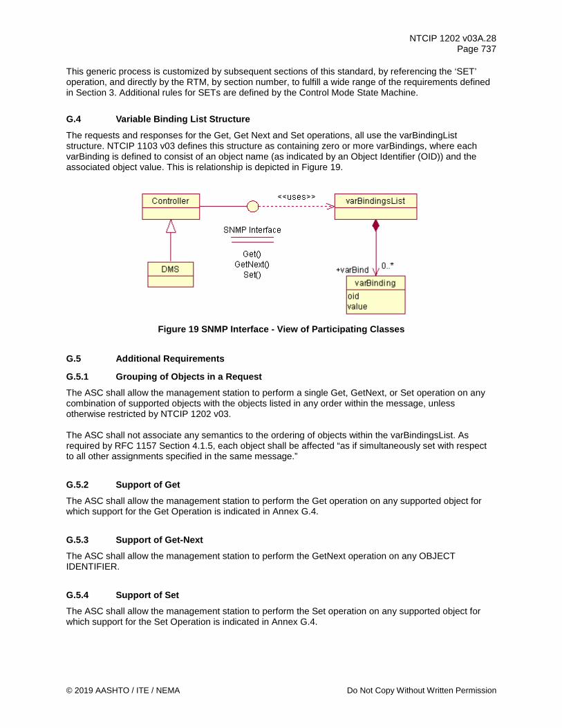
NTCIP 1202 v03A.28 Page 737
© 2019 AASHTO / ITE / NEMA Do Not Copy Without Written Permission
This generic process is customized by subsequent sections of this standard, by referencing the ‘SET’ operation, and directly by the RTM, by section number, to fulfill a wide range of the requirements defined in Section 3. Additional rules for SETs are defined by the Control Mode State Machine.
G.4 Variable Binding List Structure The requests and responses for the Get, Get Next and Set operations, all use the varBindingList structure. NTCIP 1103 v03 defines this structure as containing zero or more varBindings, where each varBinding is defined to consist of an object name (as indicated by an Object Identifier (OID)) and the associated object value. This is relationship is depicted in Figure 19.
Figure 19 SNMP Interface - View of Participating Classes
G.5 Additional Requirements
G.5.1 Grouping of Objects in a Request The ASC shall allow the management station to perform a single Get, GetNext, or Set operation on any combination of supported objects with the objects listed in any order within the message, unless otherwise restricted by NTCIP 1202 v03. The ASC shall not associate any semantics to the ordering of objects within the varBindingsList. As required by RFC 1157 Section 4.1.5, each object shall be affected “as if simultaneously set with respect to all other assignments specified in the same message.”
G.5.2 Support of Get The ASC shall allow the management station to perform the Get operation on any supported object for which support for the Get Operation is indicated in Annex G.4.
G.5.3 Support of Get-Next The ASC shall allow the management station to perform the GetNext operation on any OBJECT IDENTIFIER.
G.5.4 Support of Set The ASC shall allow the management station to perform the Set operation on any supported object for which support for the Set Operation is indicated in Annex G.4.

NTCIP 1202 v03A.28 Page 738
Do Not Copy Without Written Permission © 2019 AASHTO / ITE / NEMA
G.5.5 Performance The ASC shall process the Get, GetNext, or Set request in accordance with all of the rules of NTCIP 1103 v03, including updating the value in the database and initiating the transmission of the appropriate response (assuming that the ASC has permission to transmit) within 1 second of receiving the last byte of the request.
Note: If a user desires a shorter response time, the user needs to specify this in the agency procurement specification.
G.5.6 Properly Defined Objects Every supported object shall be defined in a manner that conforms to RFC 1212 and shall have a unique OBJECT IDENTIFIER properly registered under the ISO Naming Tree. If the definition of the supported object is controlled by parties within the ITS community, the object definition should also conform to NTCIP 8004 v02.

NTCIP 1202 v03A.28 Page 739
© 2019 AASHTO / ITE / NEMA Do Not Copy Without Written Permission
Annex H NTCIP 1201 v03- and NTCIP 1103 v03-Derived Functional Requirements and
Dialogs [Normative]
Annex H serves as a reference for NTCIP 1202 v03. Eventually this reference information may be moved to successors of NTCIP 1201 v03 and NTCIP 1103 v03.
Note: At the time, the ASC WG needed to reference certain information from NTCIP 1103 (Transportation Management Protocols) and NTCIP 1201 (Global Object Definitions), such as the functional requirements and dialogs. However, neither NTCIP 1103 or NTCIP 1201 contained this type of information to the extent necessary. The ASC WG, with support from the responsible NTCIP WG and from NEMA, developed and provided the following temporary references in NTCIP 1202 v03 Annex H. When NTCIP 1103 and NTCIP 1201 support the information, then NTCIP 1202 v03 Annex H is slated for removal.
H.1 Generic Functional Requirements The following functional requirements address features defined in NTCIP 1201 v03.
H.1.1 Generic Configuration Requirements Requirements for configuring a device controller follow.
H.1.1.1 Determine Device Component Information Upon request from a management station, the ASC shall return the identification information for each module contained in the device including:
a) An indication of the type of ASC b) The manufacturer of the module c) The model number or firmware reference of the module d) The version of the module e) An indication of whether it is a software or hardware module
H.1.1.2 Determine Device Configuration Identifier Requirements The requirements to create ASC-specific configuration identifier information for configuration parameters defined within the ASC database follow.
H.1.1.2.1 Determine Unique Deployment Configuration Identifier Upon request from a management station, the ASC shall return the identifier created using a checksum-creation-like approach across all configuration parameters contained in the ASC database, which the ASC creates across all configuration parameter values at powerup and updated whenever changes are made to any of the configuration parameters.
Note: While the order of the configuration parameters within the ASC database to create the unique configuration identifier is not important, the number and actual configuration parameters to be used to create the identifier is essential to determine whether any, but not which, changes to the configuration parameters contained within the ASC database have been made.

NTCIP 1202 v03A.28 Page 740
Do Not Copy Without Written Permission © 2019 AASHTO / ITE / NEMA
H.1.1.2.2 Determine Configuration Identifier Parameter Content Upon request from a management station, the ASC shall return the configuration parameters being used to create configuration parameter identifier by listing all configuration parameters based on their SNMP Object Identifiers (Object OIDs) including scalar and instance indicators and starting with configuration parameter OIDs defined in the NTCIP standards and followed by any manufacturer-specific configuration parameter OIDs.
H.1.1.3 Determine Supported Standards Upon request from a management station, the ASC shall return the NTCIP standards which it supports.
H.1.1.4 Manage Unique System Name Upon request from a management station, the ASC shall return the system name of the ASC. This unique system name could be any unique number such as a serial number or another unique number.
H.1.1.5 Manage Time Requirements for managing the controller's clock follow.
H.1.1.5.1 Configure Time Upon request from a management station, the ASC shall store the coordinated universal time to the nearest second.
H.1.1.5.2 Configure Time Zone Upon request from a management station, the ASC shall store the time zone in which the ASC is located.
H.1.1.5.3 Configure Daylight Saving Mode Upon request from a management station, the ASC shall store whether or not daylight saving time adjustments should be performed when determining local time.
H.1.1.5.4 Determine Time Setting Upon request from a management station, the ASC shall return the coordinated universal time settings, to the nearest second.
H.1.1.5.5 Determine Time Zone Setting Upon request from a management station, the ASC shall return the time zone setting defined within the ASC.
H.1.1.5.6 Determine Daylight Saving Mode Setting Upon request from a management station, the ASC shall return the daylight saving time setting (whether or not adjustments should be performed when determining the local time).
H.1.1.5.7 Monitor Current Time Upon request from a management station, the ASC shall return the current time as set within the controller.

NTCIP 1202 v03A.28 Page 741
© 2019 AASHTO / ITE / NEMA Do Not Copy Without Written Permission
H.1.1.6 Managing Auxiliary Ports Requirements Requirements for managing the auxiliary input and output ports follow.
H.1.1.6.1 Determine External Port Information Upon request from a management station, the ASC shall return the number of auxiliary ports and the following information for each port:
a) an indication of whether the port is analog or digital b) a description of the port c) an indication of the port resolution d) an indication of whether the port can be used for input, output, or both
H.1.1.6.2 Configure Port Information Upon request from a management station, the ASC shall store the indicated description for the indicated auxiliary port.
H.1.1.6.3 Required Number of Auxiliary Ports Upon request from a management station, the ASC shall support the number of analog auxiliary ports of the resolution and direction (input, output, or bidirectional) contained in the agency procurement specification. If the agency procurement specification does not define the number, resolution, or direction of analog ports, the ASC supports at least one binary analog output port for external devices.
H.1.1.7 Manage Generic Scheduler Requirements Requirements for managing the scheduler follow.
H.1.1.7.1 Configure Timebased Scheduler Month-Day-Date Upon request from a management station, the ASC shall store the month, day of month, or day of week settings for each day plan for as far as two years in advance within the scheduler. The selection process is first based on the month settings, then the day of month (date) settings, and then the day of week (day) settings.
H.1.1.7.2 Configure Timebased Scheduler Day Plans and Timebased Actions Upon request from a management station, the ASC shall store the day plans within the scheduler, which points to actions to be executed when the month, day or date and the time within the day plan have been reached (and no other actions, such as manual control overriding timebased scheduling, inhibits the execution of the action).
H.1.1.8 Manage Security Definitions Requirements Requirements for managing the security protections expressed by username and password combinations and assignments of allowed data access for each follow.
H.1.1.8.1 Configure Security Definitions Upon request from a management station, the ASC shall store the configuration of the authorized users, their passwords, and the rights associated with the functions and database of the ASC. The ASC ensures that the configuration can only be edited and modified by authorized users with ASC-specific system-administrative rights.

NTCIP 1202 v03A.28 Page 742
Do Not Copy Without Written Permission © 2019 AASHTO / ITE / NEMA
H.1.1.9 Manage Dynamic Objects Requirements Requirements for managing the dynamic objects, which are used to compress the data transmissions of user-selected data for data collection and data configuration follow.
H.1.1.9.1 Configure Dynamic Object Requirements The requirements to configure Dynamic Objects within the ASC follow.
H.1.1.9.1.1 Configure Dynamic Object Persistence Time Upon request from a management station, the device shall store the maximum power outage time, in minutes, before all values in the dynamic objects in the device are invalidated. Valid values are from 0 to 65534 minutes. A value of 0 indicates that all values in the dynamic objects are invalidated upon device power up. A value of 65535 indicates that all values persist indefinitely.
H.1.1.9.1.2 Configure Dynamic Object Configuration ID Upon request, the device shall store an identifier, which is calculated using all valid values in the dynamic objects. The identifier, which may be a checksum, is generated whenever there is a change to any value in the dynamic objects. The identifier is used to detect any changes to the configuration of dynamic objects.
H.1.1.10 Manage Exception Reporting Requirements The requirements to manage exception reporting are as follows. A detailed explanation of how the design content (that are traced from these requirements) work can be found in Section 6 of NTCIP 1103 v03.
H.1.1.10.1 Enable/Disable Exception Reporting The management station shall be able to enable and disable exception-based reporting for an ASC when user-specified conditions are met.
H.1.1.10.2 Configure Exception Reporting Condition Requirements If exception based reporting is supported, a management station needs to specify the conditions under which the ASC is to automatically transmit data to the management station. The requirements to configure the user-specified conditions that the ASC will monitor upon which the ASC will transmit data to a management station follow.
H.1.1.10.2.1 Configure a Monitored (Watch) Object Upon request from a management station, the ASC shall store the data element to be monitored for a specified change. The allowable changes, if supported by the ASC, are:
a) On-change Event - monitor the data element for changes in value b) Greater Than Event - monitor the data element for values exceeding a defined threshold c) Less Than Event - monitor the data element for values falling below a defined threshold d) Hysteresis Event - monitor the data element for values exceeding an upper limit or dropping
below a lower limit e) Periodic Event - monitor the data element and create a log entry at user-defined intervals f) Bit Flag Event - monitor the data element for one or more bits of a value becoming true (i.e.,
obtaining a value of one)
NTCIP 1202 v03A.28 Page 743
© 2019 AASHTO / ITE / NEMA Do Not Copy Without Written Permission
H.1.1.10.2.2 Configure a Monitored Group of Objects (Watch Block) Upon request from a management station, the ASC shall store a group of one or more data elements (watch block) to be monitored to determine if a change has occurred to any data element in the group. This requirement allows an ASC to monitor two or more objects such that a change to any of the data elements in the group triggers the ASC to transmit preconfigured data value(s) to a management station. Monitoring a group of data elements provides the ASC with flexibility for supporting event logging and exception-based reporting with a wide variety of possible triggers.
H.1.1.10.3 Configure Exception Reporting Data Transmission Requirements If exception based reporting is supported, a management station needs to specify the data to be automatically transmitted by the ASC if user-specified conditions are satisfied. The requirements to configure the data to be automatically transmitted by the ASC to a management station when a monitored condition occurs follow.
H.1.1.10.3.1 Configure a Report Object Upon request from a management station, the ASC shall store a data element whose value is to be transmitted to a management station when a user-specified condition occurs.
H.1.1.10.3.2 Configure a Report Group of Objects (Block) Upon request from a management station, the ASC shall store a group of one or more data elements whose values are to be transmitted to a management station when a user-specified condition occurs. Creating a block object, called a report block, containing this group of data to be transmitted reduces the transmission overhead.
H.1.1.10.4 Configure Exception Reporting Destination Upon request from a management station, the ASC shall store the destination(s), in the form of a logical name and an IP address, that pre-configured data is to be transmitted when the user-specified conditions are met. This requirement allows the management station to specify the destination(s) that the pre-configured data is to be transmitted when a user-specified condition occurs.
H.1.1.10.5 Configure Exception Reporting Community Upon request from a management station, the ASC shall store the community name to use when pre-configured data is transmitted when the user-specified conditions are met. This requirement allows the management station to specify the community to use for each destination that the pre-configured data is transmitted when a user-specified condition occurs.
H.1.1.10.6 Configure Exception Reporting Operational Mode Requirements A management station needs to configure the operation of how and when the pre-configured data is transmitted from the ASC to its destination, and the response of the destination management station when the data transmission is received. The requirements to configure the operations for exception-based reporting follows.
H.1.1.10.6.1 Configure Exception Reporting Acknowledgement Upon request from a management station, the ASC shall store if an acknowledgement is expected from the destination management station when pre-configured data is transmitted when user-specified conditions are met. If an acknowledgement is expected, the destination management station is expected to acknowledge receipt of the pre-configured data back to the ASC. If an acknowledgement from the

NTCIP 1202 v03A.28 Page 744
Do Not Copy Without Written Permission © 2019 AASHTO / ITE / NEMA
destination management station is not received, the ASC will retransmit (retry) the data until an acknowledgement is received or the maximum number of retries is reached.
H.1.1.10.6.2 Configure Exception Reporting Aggregation Upon request from a management station, the ASC shall configure if the pre-configured data to be transmitted when user-specified conditions are met is aggregated before actual transmission. If enabled, pre-configured data to be transmitted is aggregated until a specific event occurs, until enough events have occurred, or until the buffer with the aggregated data has been filled. Support for aggregated data transmissions allows the reduction of data transmissions, reduces message overhead, and aggregates the data transmissions until the communications channel to management station is available.
H.1.1.10.6.3 Configure Exception Reporting Queue Upon request from a management station, the ASC shall configure if the pre-configured data to be transmitted when user-specified conditions are met is queued until the communications link between the ASC and the destination management station is available for transmission. If enabled, pre-configured data to be transmitted to a destination management station is queued until an acknowledgement is received (if acknowledgement is expected) and other previously transmitted pre-configured data in the queue is acknowledged (if acknowledgement is expected), OR an error condition for the communications link between the ASC and destination management station is cleared.
H.1.1.10.6.4 Configure Exception Reporting (Forced) Upon request from a management station, the ASC shall store if a pre-configured data to be transmitted immediately (forced) when user-specified conditions are met. If a data transmission is 'forced', the data transmission is not queued and is transmitted regardless of the current link state between the ASC and the destination management station. 'Forced' data transmissions do not require any acknowledgement from the destination management station.
H.1.1.10.6.5 Configure Exception Reporting Communications Upon request from a management station, the ASC shall store the communications protocols to be used transmit pre-configured data to a destination. The communications protocols consist of the application layer protocol (snmp v1, sfmp), transport profile (T2 encapsulation, udp), and port of the destination management station.
H.1.1.10.6.6 Configure Exception Reporting - Maximum Rate Upon request from a management station, the ASC shall store the maximum number of data transmissions that can be generated in one minute for a specific communications link. This requirement prevents an ASC from flooding the communications network with exception-based messages.
H.1.1.10.7 Determine Watch Block Capabilities Upon request from a management station, the ASC shall report the maximum number of data elements that the ASC can include in the watch blocks and the maximum number of watch blocks that can be configured in the ASC.
H.1.1.10.8 Determine Report Block Capabilities Upon request from a management station, the ASC shall report the maximum number of data elements that the ASC can log in the report blocks and the maximum number of report blocks that can be configured in the ASC.

NTCIP 1202 v03A.28 Page 745
© 2019 AASHTO / ITE / NEMA Do Not Copy Without Written Permission
H.1.1.10.9 Determine Exception Reporting Trap Channel Capabilities Upon request from a management station, the ASC shall report the maximum number of "trap channels" supported by the ASC. Each trap channel defines the destination management station, the communications protocols to be used, and an operational configuration for how and when the pre-configured data is transmitted from the ASC to its destination, and the response of the destination management station when the data transmission is received.
Note: The concept of a trap channel is introduced here for clarity.
H.1.1.10.10 Determine Exception Reporting Aggregation Capabilities Upon request from a management station, the ASC shall report the capabilities of the ASC to aggregate pre-configured data for transmission. The ASC's capabilities for exception reporting data is defined by the maximum number of events (user-defined conditions that are met) and the maximum size (in bytes) of aggregated data (for transmission).
H.1.1.10.11 Determine Event Reporting Latency Upon request from a management station, the ASC shall report the maximum amount of time, in milliseconds, that may elapse between an event's occurrence and the time reported for that event. The latency should consider all sources of latency, including hardware and firmware delays. The range of values is from 0 to 1000 milliseconds. A value of 0 indicates that the ASC reports accurate event times with millisecond resolution. A value of 1000 indicates that the device cannot accurately report sub-second event times.
H.1.1.10.12 Monitor Communications Link State Upon request from a management station, the ASC shall return the state of the communications link for a specific trap channel. The valid status values are as follows:
a) Ready - Any exception report data can be sent to the destination management station b) Pending - Waiting for an acknowledgement from the destination management station for the last
transmitted exception report data c) Error - An acknowledgement has not been received from the destination management station for
the last transmitted exception report data and the allowed number of retries (to resend the exception report data) has been exceeded.
d) Other - State not defined by this standard
H.1.1.10.13 Monitor Exception Based Reporting Status Requirements The requirements to determine the status of an alarm for a specific trap channel follow.
H.1.1.10.13.1 Monitor Exception Based Communications Link Error Upon request from a management station, the ASC shall return an alarm value when there is an error in the communications link of a specific trap channel.
H.1.1.10.13.2 Monitor Exception Based Maximum Rate Exceeded Upon request from a management station, the ASC shall return an alarm value when the number of data transmissions generated exceeds the maximum number of allowable data transmissions in a minute for a specific trap channel.
NTCIP 1202 v03A.28 Page 746
Do Not Copy Without Written Permission © 2019 AASHTO / ITE / NEMA
H.1.1.10.13.3 Monitor Exception Based Queue Full Error Upon request from a management station, the ASC shall return an alarm value when the queue for pre-configured data to be transmitted on a specific trap channel is full.
H.1.1.10.14 Monitor Exception Based Transmissions Upon request from a management station, the ASC shall return the sequence number assigned to the last data transmission on a specific trap channel. This requirement allows a management station to determine if a data transmission on the trap channel is a duplicate or if a data transmission has been lost.
H.1.1.10.15 Monitor Number of Lost Queued Exception Based Reports Upon request from a management station, the ASC shall return the number of exception based reports that have been discarded due to a queue full error for a specific trap channel. This requirement allows a management station to determine if exception based reports have been lost because of a queue full error.
H.1.1.10.16 Monitor Number of Exception Based Events Upon request from a management station, the ASC shall return the number of occurrences of a user-specified condition for a specific trap channel since the last reset of the ASC.
H.1.1.10.17 Monitor Exception Based Data Upon request from a management station, the ASC shall return the contents of a trap message. A trap message consists of the user-specified condition that triggered the exception based report and the pre-configured data. If the pre-configured data is aggregated, the trap message also contains a sequence number assigned to the aggregated data.
H.1.1.10.18 Clear Event Class Upon request from a management station, the ASC shall clear all information related to the requested event class from the report node (globalReport).
H.1.1.10.19 Clear Event Configuration Upon request from a management station, the ASC shall clear all information related to the requested event configuration from the report node (globalReport).
H.1.1.10.20 Clear Event Log Table Upon request from a management station, the ASC shall clear all the log entries from the event logs.
H.1.1.10.21 Clear Report Objects Upon request from a management station, the ASC shall clear all report objects and report block definitions in the ASC.
H.1.1.10.22 Clear Report Blocks Upon request from a management station, the ASC shall delete all report blocks definitions in the ASC.
H.1.1.10.23 Clear Watch Objects Upon request from a management station, the ASC shall clear all watch objects and watch block definitions in the ASC.
NTCIP 1202 v03A.28 Page 747
© 2019 AASHTO / ITE / NEMA Do Not Copy Without Written Permission
H.1.1.10.24 Clear Watch Blocks Upon request from a management station, the ASC shall delete all watch blocks definitions in the ASC.
H.1.1.10.25 Clear Exception Based Reporting Tables Upon request from a management station, the ASC shall clear all the user-specified conditions for automatically transmitting data to the management station.
H.1.1.10.26 Reset a Communications Link Upon request from a management station, the ASC shall reset a communications link providing exception-based data to be acknowledged. For such communications links, a sequence number is included with each piece of exception-based data transmitted - no additional exception-based data is transmitted on this communications link by the ASC until the previously transmitted data is acknowledged or the communications link is reset (in case the data is lost in transit).
H.1.2 Generic Status Monitoring Requirements Requirements for monitoring the status of a ASC controller follow.
H.1.2.1 Monitor Status of External Device Upon request from a management station, the ASC shall return the following information for the indicated auxiliary port:
a) Current state b) Last commanded state
H.1.2.2 Retrieve Database Management Requirements Requirements for monitoring the database management within the ASC follow.
H.1.2.2.1 Monitor Database Operation Upon request from a management station, the ASC shall return the current database management function status such as opening the database, allowing data to be written into the database, verify the validity and coherence of the written data, and close the database, after which time, the ASC starts using the new data.
H.1.2.2.2 Monitor Database Operation Status Upon request from a management station, the ASC shall return the current database management function status to determine whether a database modification action was successfully executed by the ASC.
H.1.2.2.3 Monitor Database Operation Error Status Upon request from a management station, the ASC shall return the current database management function status to determine which error has occurred in conjunction with the modification of the database values.

NTCIP 1202 v03A.28 Page 748
Do Not Copy Without Written Permission © 2019 AASHTO / ITE / NEMA
H.1.2.3 Retrieve Generic Scheduler Settings Requirements Requirements for retrieving the scheduler data follow.
H.1.2.3.1 Monitor Timebased Scheduler Month-Day-Date Upon request from a management station, the ASC shall return the month, day of month, or day of week settings for each defined day plan configured for as far as 2 years in advance within the scheduler.
H.1.2.3.2 Monitor Timebased Scheduler Day Plans and Timebased Actions Upon request from a management station, the ASC shall return the hour and minute settings and the action to be executed for each defined day plan and defined day plan event configured within the scheduler. A defined action is executed when the month, date, day and the time (hour and minute) within the day plan have been reached.
H.1.2.3.3 Monitor Active Timebased Schedule Upon request from a management station, the ASC shall return the Month-Day-Date entry within the scheduler that is currently selected for use.
Note: A schedule entry indicated to be active does not mean that this schedule entry is actually active (because other actions within the device, such as manual control overriding timebased scheduling, might override the activation and use of the selected day plan).
H.1.2.3.4 Monitor Active Timebased Schedule Day Plan and Timebased Actions Upon request from a management station, the ASC shall return the day plan within the scheduler that is currently selected for use.
Note: A day plan indicated to be active does not mean that this plan is actually active (because other actions within the ASC, such as manual control overriding timebased scheduling, might override the activation and use of the selected day plan).
H.1.2.4 Retrieve Security Definitions Requirements Requirements for monitoring the security protections expressed by username and password combinations and assignments of allowed data access for each are provided in the following subsections.
H.1.2.4.1 Determine Security Definitions Upon request from a management station, the ASC shall return the configuration of the authorized users, their passwords, and the rights associated with the functions and database of the ASC. The ASC ensures that the configuration can only be viewed by authorized users with ASC-specific system-administrative rights.
H.1.2.5 Retrieve Dynamic Objects Requirements Requirements for retrieving the dynamic objects, which are used to compress the data transmissions of user-selected data for data collection and data configuration are provided in the following subsections.
H.1.2.5.1 Determine Dynamic Objects Requirements The requirements to determine the configuration settings for Dynamic Objects within the ASC follow.

NTCIP 1202 v03A.28 Page 749
© 2019 AASHTO / ITE / NEMA Do Not Copy Without Written Permission
H.1.2.5.1.1 Determine Dynamic Object Persistence Time Upon request, the device shall return the maximum power outage time, in minutes, before all values in the dynamic objects in the device are invalidated. Valid values are from 0 to 65534 minutes. A value of 0 indicates that all values in the dynamic objects are invalidated upon device power up. A value of 65535 indicates that all values persist indefinitely.
H.1.2.5.1.2 Determine Dynamic Object Configuration ID Upon request, the device shall return an identifier, which is calculated using all valid values in the dynamic objects. The identifier, which may be a checksum, is generated whenever there is a change to any value in the dynamic objects. The identifier is used to detect any changes to the configuration of dynamic objects.
H.1.2.5.2 Monitor STMP-related Communications Requirements The requirements to retrieve the statistics for the data exchanges between a management center and an ASC when using the Simple Transportation Management Protocol (STMP) follow.
H.1.2.5.2.1 Monitor STMP Data Exchange Requirements The requirements to determine the statistics pertaining to STMP data exchanges such as the number of GETs or SETs, and other statistical information within the ASC follow.
H.1.2.5.2.1.1 Monitor Incoming and Outgoing STMP Packet Exchanges Upon request from a management station, the ASC shall return the statistics pertaining to incoming and outgoing STMP data packet exchanges.
H.1.2.5.2.1.2 Monitor Incoming and Outgoing STMP Packet Types Upon request from a management station, the ASC shall return the statistics pertaining to incoming and outgoing STMP data packet types such as GET, SET, and GETNext Requests, SET, SET-NoReplies, and Error Responses.
H.1.2.5.2.2 Monitor STMP Data Exchange Error Requirements The requirements to determine the error statistics pertaining to STMP data exchanges such as the number of failed data exchanges, data package size errors within the ASC follow.
H.1.2.5.2.2.1 Monitor Incoming and Outgoing STMP Error Exchanges - Too Big Error Upon request from a management station, the ASC shall return the error statistics pertaining to incoming and outcoming STMP data exchanges with errors based on the data packets being too big.
H.1.2.5.2.2.2 Monitor Incoming and Outgoing STMP Error Exchanges - No Such Name Upon request from a management station, the ASC shall return the error statistics pertaining to incoming and outcoming STMP data exchanges with no such name errors.
H.1.2.5.2.2.3 Monitor Incoming and Outgoing STMP Error Exchanges - Bad Value Upon request from a management station, the ASC shall return the error statistics pertaining to incoming and outcoming STMP data exchanges with bad value errors.

NTCIP 1202 v03A.28 Page 750
Do Not Copy Without Written Permission © 2019 AASHTO / ITE / NEMA
H.1.2.5.2.2.4 Monitor Incoming and Outgoing STMP Error Exchanges - Read-Only Upon request from a management station, the ASC shall return the error statistics pertaining to incoming and outcoming STMP data exchanges containing SET commands to read-only objects.
H.1.2.5.2.2.5 Monitor Incoming and Outgoing STMP Error Exchanges - General Error Upon request from a management station, the ASC shall return the error statistics pertaining to incoming and outcoming STMP data exchanges with general errors.
H.1.3 Generic Data Retrieval Requirements There are no data retrieval requirements for a generic device controller.
H.1.3.1 Support Logged Data Requirements for managing the logged data follow.
H.1.3.1.1 Retrieve Current Configuration of Logging Service Upon request from a management station, the ASC shall return the current configuration of the event logging service, including the classes and types of events that are currently configured.
H.1.3.1.2 Configure Event Logging Service Upon request from a management station, the ASC shall configure the event logging service as requested, including configuration of the event classes and event types to log.
H.1.3.1.3 Retrieve Event Logged Data Upon request from a management station, the ASC shall return the event log.
H.1.3.1.4 Configure Clearing of Event Class Log Upon request from a management station, the ASC shall clear the indicated log entries of a given event class that are less than or equal to a given time.
H.1.3.1.5 Determine Capabilities of Event Logging Service Upon request from a management station, the ASC shall return the capabilities of the event logging service, including the number of classes, number of event types, and number of events that can be supported by the ASC.
H.1.3.1.6 Determine Number of Logged Events per Event Class Upon request from a management station, the ASC shall return the total number of events within the event class that the device has currently in its event log.
H.1.3.1.7 Support a Number of Events to Store in Log Upon request from a management station, the ASC event log shall support the number of events as defined in the agency procurement specification, up to a maximum of 65535 events. If the agency procurement does not define the number of events for the log, the ASC supports at least one event in the log.
NTCIP 1202 v03A.28 Page 751
© 2019 AASHTO / ITE / NEMA Do Not Copy Without Written Permission
H.1.3.1.8 Configure Clearing of Global Log Upon request from a management station, the ASC shall allow a management station to clear all log entries in the event log.
H.1.3.1.9 Determine Total Number of Logged Events Upon request from a management station, the ASC shall allow a management station to determine the total number of events that the ASC has logged since powerup.
H.1.3.1.10 Determine Number of Events within a Class Upon request from a management station, the ASC shall allow a management station to determine the number of events that the ASC has in the log for a specified event class.
H.1.3.1.11 Determine Event Logging Resolution Upon request from a management station, the ASC shall return the frequency (resolution) with which the ASC logs new events within the log, separately for each event class, with a resolution of 0.1 seconds.
H.1.3.1.12 Clear Event Configuration Upon request from a management station, the ASC shall allow a management station to clear one or all event configurations, except for the pre-configured event configurations.
H.1.3.1.13 Clear Event Classes Upon request from a management station, the ASC shall allow a management station to clear one or all existing event classes, except for the pre-configured event classes.
H.1.3.1.14 Clear Event Class Log Upon request from a management station, the ASC shall allow a management station to clear all logged events for the event classes.
H.1.3.1.15 Retrieve Non-Sequential Clock Changes Upon request from a management station, the ASC shall allow a management station to retrieve the timestamp, the new time, and the source of the new time that caused a non-sequential clock change.
H.1.3.2 Supplemental Requirements for Event Monitoring Supplemental requirements for monitoring for the occurrence of certain events follow.
H.1.3.2.1 Record and Timestamp Events Upon request from a management station, the ASC shall support the capability to record configured event types with timestamps, in a local log (log contained in the device controller), upon request by the user and/or the management station.
H.1.3.2.2 Support a Number of Event Classes Upon request from a management station, the ASC shall support the number of event classes as defined by the specification. If the specification does not define the number of event classes, the ASC supports at least one event class.

NTCIP 1202 v03A.28 Page 752
Do Not Copy Without Written Permission © 2019 AASHTO / ITE / NEMA
H.1.3.2.3 Support a Number of Events to Log Upon request from a management station, the ASC shall support the maximum number of events as defined by the specification.
H.1.3.2.4 Support Monitoring of Event Type Requirements Supplemental requirements for monitoring types of events follow.
H.1.3.2.4.1 Support On-Change Events Upon request from a management station, the ASC shall allow any event type configuration to monitor data for changes in value.
H.1.3.2.4.2 Support Greater Than Events Upon request from a management station, the ASC shall allow any event type configuration to monitor data for values exceeding a defined threshold for a period of time.
H.1.3.2.4.3 Support Less Than Events Upon request from a management station, the ASC shall allow any event type configuration to monitor data for values falling below a defined threshold for a period of time.
H.1.3.2.4.4 Support Hysteresis Events Upon request from a management station, the ASC shall allow any event type configuration to monitor data for values exceeding an upper limit or dropping below a lower limit.
H.1.3.2.4.5 Support Periodic Events Upon request from a management station, the ASC shall allow any event type configuration to monitor data on a periodic basis.
H.1.3.2.4.6 Support Bit Flag Events Upon request from a management station, the ASC shall allow any event type configuration to monitor one or more bits of a value becoming true (e.g., obtaining a value of one).
H.1.3.2.4.7 Support Event Monitoring on Any Data Upon request from a management station, the ASC shall allow a management station to configure any event type to monitor any piece of data supported by the ASC within the logical rules of the type of event (e.g., ASCII strings should not be monitored with greater than or less than conditions).
Note: This allows a user to monitor an event based on the value of any data.
H.1.4 Generic Control Requirements Requirements for controlling a ASC controller follow.
H.1.4.1 Control External Device Upon request from a management station, the ASC shall activate or de-activate, as requested, a simple external device connected through an analog auxiliary port.

NTCIP 1202 v03A.28 Page 753
© 2019 AASHTO / ITE / NEMA Do Not Copy Without Written Permission
H.1.4.2 Control Database Operation Requirements Requirements for controlling the operations on the ASC database follow.
H.1.4.2.1 Control Database Access Upon request from a management station, the ASC shall allow to open or close the ASC database and if open, to allow data to be written into the database.
H.1.4.2.2 Perform Database Consistency Check Upon request from a management station, the ASC shall allow to perform consistency checks within database to verify the validity and coherence of the written data. Once the consistency checks have been passed successfully, the ASC starts using the new data.
H.1.4.2.3 Enforce Consistency Check Parameters Upon request to store specific database parameter from a management station, the ASC shall enforce that specific database parameters can only be stored in the ASC’s database, if they are set as part of a database consistency check (and not with a direct SNMP or STMP SET command). The ASC returns an SNMP general error, if the management station attempts to store one of these specific database parameters bypassing the consistency check.
H.1.5 Generic Performance Requirements H.1.5.1 Atomic Operations Reports shall be generated based on atomic operations to prevent multiple reports of the same atomic event. The guidelines for timing and atomic operations are found in NTCIP 1103 v03, Section 6.1.1.
H.2 Derived GLOBAL Dialogs
H.2.1 Manage Communications Environment Standardized dialogs for managing the communications environment that are more complex than simple GETs or SETs are defined in the following subsections.
H.2.1.1 Retrieve Current Configuration of Event Reporting and Logging Service The standardized dialog for a management station to determine the current configuration of the logging service and/or exception reporting events shall be as follows:
a) (Precondition) The management station shall be aware of the number of classes and event configurations supported by the ASC. (See Annex A for Requirement 3.4.2.5)
b) For each row of the event class table, the management station shall GET the following data: 1) eventClassLimit.x 2) eventClassClearTime.x 3) eventClassDescription.x
c) For each row of the event configuration table, the management station shall GET the following data: 1) eventConfigClass.y 2) eventConfigMode.y 3) eventConfigCompareValue.y 4) eventConfigCompareValue2.y 5) eventConfigCompareOID.y 6) eventConfigLogOID.y

NTCIP 1202 v03A.28 Page 754
Do Not Copy Without Written Permission © 2019 AASHTO / ITE / NEMA
7) eventConfigAction.y 8) eventConfigStatus.y
Where:
x = event class number y = event configuration identifier
H.2.1.2 Configuring Reporting/Logging Service The standardized dialog for a management station to configure the logging service or events to be reported shall be as follows:
a) (Precondition) The management station shall determine that there are sufficient rows in the event configuration and event class tables to download the proposed configuration.
b) The management station shall SET the following data to the desired values to configure each desired event class: 1) eventClassLimit.x 2) eventClassClearTime.x 3) eventClassDescription.x
Note: Each event type to be monitored is classified into one event class. For example, critical events may be grouped into Class 1 events and warnings may be grouped into Class 2 events. This step, defines the structure of each class of events.
c) The management station shall SET the following data to the desired values to configure each
desired event to be monitored: 1) eventConfigClass.y 2) eventConfigMode.y 3) eventConfigCompareValue.y 4) eventConfigCompareValue2.y 5) eventConfigCompareOID.y 6) eventConfigLogOID.y 7) eventConfigAction.y
Note: Depending on the value of eventConfigMode, not all other objects may be necessary for the event to be defined, however, they shall always be SET as a part of the standardized dialog.
d) The management station shall GET eventConfigStatus.y to check that there is not an error in the
configuration.
Where: x = event class number y = event configuration identifier
H.2.1.3 Retrieving Logged Data The standardized dialog for a management station to retrieve logged data shall be as follows:
a) (Precondition) The management station shall be aware of the number of events that had previously been reported for the device for the subject event class (e.g., from the previous performance of this operation).
b) The management station shall GET the following data: 1) eventClassNumRowsInLog.x 2) eventClassNumEvents.x

NTCIP 1202 v03A.28 Page 755
© 2019 AASHTO / ITE / NEMA Do Not Copy Without Written Permission
c) If eventClassNumEvents.x has not changed since the previous reading, the management station shall exit the process. Otherwise, the management station shall determine the additional number of events that have occurred since the last read. Note: This is generally determined by subtracting the previous number of events from eventClassNumEvents; however, since this object wraps at 65535, the management station should be prepared to determine the differential if eventClassNumEvents is less than the previous number.
d) The management station shall determine the lesser of eventClassNumRowsInLog and the additional number of events that have occurred since the last read. This number shall be termed the Events to Read.
e) Starting with y = eventClassNumRowsInLog and working down until y = (eventClassNumRowsInLog - Events to Read), the management station shall GET the following data: 1) eventLogID.x.y 2) eventLogTime.x.y 3) eventLogValue.x.y
f) Repeat the same GET operation with y decremented by one (1) for each set of duplicated values (until y reaches a value of zero (0)).
Note: If the event class is full and another event occurs, the new event is recorded in the last entry and all previously logged data is moved to one index lower with index 1 being deleted from the table. Thus, if a duplicate row is detected (e.g., same event at same time), it is likely an indication that the same event is being read and that a new event was added to the log. Note: The management station may wish to clear the event log after the read to minimize the above problem.
Where:
x = event log class y = event log number
H.2.2 Determining Device Component Information The standardized dialog for a management station to identify the hardware and software configuration of a NTCIP device shall be as follows:
a) The management station shall GET the object globalMaxModules.0. b) For each row in the module table, the management station shall GET the following objects:
1) moduleDeviceNode.x, 2) moduleMake.x, 3) moduleModel.x, 4) moduleVersion.x, 5) moduleType.x.
Where:
x = module number
H.2.3 Global Time Data The following subsection identifies the interface to a field device to obtain and manage time related information.
H.2.3.1 Graphical Depiction of Global Time Data See Figure 20.
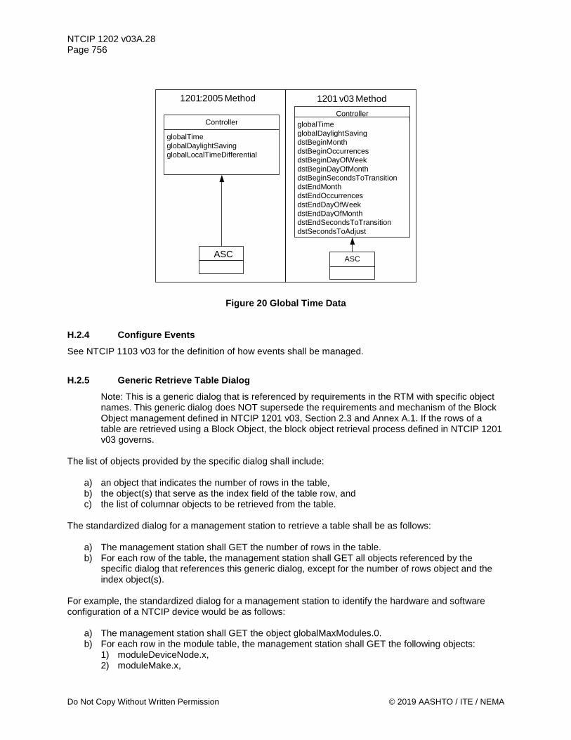
NTCIP 1202 v03A.28 Page 756
Do Not Copy Without Written Permission © 2019 AASHTO / ITE / NEMA
Figure 20 Global Time Data
H.2.4 Configure Events See NTCIP 1103 v03 for the definition of how events shall be managed.
H.2.5 Generic Retrieve Table Dialog Note: This is a generic dialog that is referenced by requirements in the RTM with specific object names. This generic dialog does NOT supersede the requirements and mechanism of the Block Object management defined in NTCIP 1201 v03, Section 2.3 and Annex A.1. If the rows of a table are retrieved using a Block Object, the block object retrieval process defined in NTCIP 1201 v03 governs.
The list of objects provided by the specific dialog shall include:
a) an object that indicates the number of rows in the table, b) the object(s) that serve as the index field of the table row, and c) the list of columnar objects to be retrieved from the table.
The standardized dialog for a management station to retrieve a table shall be as follows:
a) The management station shall GET the number of rows in the table. b) For each row of the table, the management station shall GET all objects referenced by the
specific dialog that references this generic dialog, except for the number of rows object and the index object(s).
For example, the standardized dialog for a management station to identify the hardware and software configuration of a NTCIP device would be as follows:
a) The management station shall GET the object globalMaxModules.0. b) For each row in the module table, the management station shall GET the following objects:
1) moduleDeviceNode.x, 2) moduleMake.x,
Controller globalTime globalDaylightSaving globalLocalTimeDifferential
ASC
Controller globalTime globalDaylightSaving dstBeginMonth dstBeginOccurrences dstBeginDayOfWeek dstBeginDayOfMonth dstBeginSecondsToTransition dstEndMonth dstEndOccurrences dstEndDayOfWeek dstEndDayOfMonth dstEndSecondsToTransition dstSecondsToAdjust
ASC
1201 : 2005 Method 1201 v 03 Method

NTCIP 1202 v03A.28 Page 757
© 2019 AASHTO / ITE / NEMA Do Not Copy Without Written Permission
3) moduleModel.x, 4) moduleVersion.x, 5) moduleType.x.
Where:
x = module number
H.2.6 Generic Retrieve Table Row Dialog Note: This is a generic dialog that is referenced by other dialogs with specific object names. This generic dialog does NOT supersede the requirements and mechanism of the Block Object management defined in NTCIP 1201 v03, Section 2.3 and Annex A.1. If the rows of a table are retrieved using a Block Object, the block object retrieval process defined in NTCIP 1201 v03 governs.
The list of objects provided by the specific dialog shall include:
a) the object(s) that serve as the index field of the table row, and b) the list of columnar objects to be retrieved from the table.
The standardized dialog for a management station to retrieve a table shall be as follows:
a) (Precondition) The management station shall be aware of which row of the table is to be retrieved.
b) For the specified row, the management station shall GET all objects referenced by the specific dialog that references this generic dialog, except for the index object(s).
H.2.7 Generic Configure Table Row Note: This is a generic dialog that is referenced by other dialogs with specific object names.
The list of objects provided by the specific dialog shall include:
a) the object(s) that serve as the index field of the table row, and b) the list of columnar objects to be configured and their desired values.
The standardized dialog for a management station to configure a table row shall be as follows:
a) (Precondition) The management station shall be aware of which row in the table is to be configured.
b) For the specified row, the management station shall SET all objects (to their desired values) referenced by the specific dialog that references this generic dialog, except for the index object(s).
H.3 External Data Elements NTCIP 1202 v03 references data elements within this annex that are physically defined within NTCIP 1201 v03. See NTCIP 1201 v03.

NTCIP 1202 v03A.28 Page 758
Do Not Copy Without Written Permission © 2019 AASHTO / ITE / NEMA
Annex I Communications Ports Protocols [Normative]
This annex content serves as a reference for the standardized communications protocols used by the communications ports.
Note: At the time, the ASC WG needed to reference certain information from Internet Standards and RFCs developed and maintained by the Internet Engineering Task Force (IETF). These IETF standards and RFCs do not contain either functional requirements or dialogs, which were added in Sections 3 and 4 of this document, and these standards included many options, which needed to be addressed and specified for the use within actuated signal controllers complying with NTCIP 1202 v03 (this standard). The content presented here was originally contained in NTCIP 1202v02 and has been retained, except where shown.
The different tables shown below are defined in the following RFC:
Table Name Originating IETF Standard or RFC SNMP Group RFC 1213 System Group RFC 1213 RS232 Group RFC 1317 HDLC Group RFC 1381 Interfaces Group RFC 1213 IP Group RFC 1213 ICMP Group RFC 1213 TCP Group RFC 1213 UDP Group RFC 1213 Ethernet Group RFC 1643
I.1 SNMP Group The SNMP Group shall consist of the following objects:
SNMP Group rfc
1213 Object Name
Object Type
Object Status
Object Support
Allowed Values
Supported Values
snmp SNMP Group -- M Yes --- snmp.1 snmpInPkts S snmp : M Yes Counter snmp.2 snmpOutPkts S snmp : M Yes Counter snmp.3 snmpInBadVersions S snmp : M Yes Counter snmp.4 snmpInBadCommunityNames S snmp : M Yes Counter snmp.5 snmpInBadCommunityUses S snmp : M Yes Counter snmp.6 snmpInASNParseErrs S snmp : M Yes Counter snmp.8 snmpInTooBigs S snmp : M Yes Counter snmp.9 snmpInNoSuchNames S snmp : M Yes Counter snmp.10 snmpInBadValues S snmp : M Yes Counter snmp.11 snmpInReadOnlys S snmp : M Yes Counter snmp.12 snmpInGenErrs S snmp : M Yes Counter snmp.13 snmpInTotalReqVars S snmp : O Yes / No Counter snmp.14 snmpInTotalSetVars S snmp : O Yes / No Counter snmp.15 snmpInGetRequests S snmp : M Yes Counter snmp.16 snmpInGetNexts S snmp : M Yes Counter snmp.17 snmpInSetRequests S snmp : M Yes Counter snmp.18 snmpInGetResponses S snmp : M Yes Counter

NTCIP 1202 v03A.28 Page 759
© 2019 AASHTO / ITE / NEMA Do Not Copy Without Written Permission
SNMP Group rfc
1213 Object Name
Object Type
Object Status
Object Support
Allowed Values
Supported Values
snmp.19 snmpInTraps S snmp : M Yes Counter snmp.20 snmpOutTooBigs S snmp : M Yes Counter snmp.21 snmpOutNoSuchNames S snmp : M Yes Counter snmp.22 snmpOutBadValues S snmp : M Yes Counter snmp.24 snmpOutGenErrs S snmp : M Yes Counter snmp.25 snmpOutGetRequests S snmp : M Yes Counter snmp.26 snmpOutGetNexts S snmp : M Yes Counter snmp.27 snmpOutSetRequests S snmp : M Yes Counter snmp.28 snmpOutGetResponses S snmp : M Yes Counter snmp.29 snmpOutTraps S snmp : O Yes / No Counter snmp.30 snmpEnableAuthenTraps P snmp : O Yes / No INT
SNMP Group
NTCIP 1103 Clause
Object Name
Object Type
Object Status
Object Support
Allowed Values
Supported Values
A.3.1 snmpmaxPacketSize S snmp : M Yes 484-65535
I.2 System Group The System Group shall consist of the following objects:
System Group rfc
1213 Object Name
Object Type
Object Status
Object Support
Allowed Values
Supported Values
system System Group -- M Yes --- system 1 sysDescr S system : M Yes string system 2 sysObjectID S system : M Yes OID system 3 sysUpTime S system : M Yes TimeTicks system 4 sysContact P system : M Yes string system 5 sysName P system : M Yes atring system 6 sysLocation P system : M Yes string system 7 sysServices S system : M Yes 0..127
I.3 RS232 Group The RS232 Group shall consist of the following objects:
RS232 Group rfc
1317 Object Name
Object Type
Object Status
Object Support
Allowed Values
Supported Values
rs232 RS232 Group -- O Yes / No ---- --- rs232.1 rs232Number S rs232 : M Yes INT rs232.2 rs232PortTable -- rs232 : M Yes --- ---
rs232PortEntry -- rs232 : M Yes --- --- rs232.2.1 rs232PortIndex S rs232 : M Yes INT rs232.2.2 rs232PortType S rs232 : M Yes 1..5 other(1) -- --- Yes / No --- --- rs232(2) -- --- Yes / No --- --- rs422(3) -- --- Yes / No --- --- rs423(4) -- --- Yes / No --- --- v35(5) -- --- Yes / No --- --- rs232.2.3 rs232PortInSigNumber S rs232 : O Yes / No INT rs232.2.4 rs232PortOutSigNumber S rs232 : O Yes / No INT rs232.2.5 rs232PortInSpeed P rs232 : M Yes INT rs232.2.6 rs232PortOutSpeed P rs232 : M Yes INT

NTCIP 1202 v03A.28 Page 760
Do Not Copy Without Written Permission © 2019 AASHTO / ITE / NEMA
RS232 Group rfc
1317 Object Name
Object Type
Object Status
Object Support
Allowed Values
Supported Values
rs232.3 rs232AsyncPortTable -- rs232 : M Yes --- ---
rs232AsyncPortEntry -- rs232 : M Yes --- --- rs232.3.1 rs232AsyncPortIndex S rs232 : M Yes INT rs232.3.2 rs232AsyncPortBits P rs232 : O Yes / No 5..8 five(5) -- --- Yes / No --- --- six(6) -- --- Yes / No --- --- seven(7) -- --- Yes / No --- --- eight(8) -- --- Yes / No --- --- rs232.3.3 rs232AsyncPortStopBits P rs232 : O Yes / No 1..4 one(1) -- --- Yes / No --- --- two(2) -- --- Yes / No --- --- one-and-half(3) -- --- Yes / No --- --- dynamic(4) -- --- Yes / No --- --- rs232.3.4 rs232AsyncPortParity P rs232 : O Yes / No 1..5 none(1) -- --- Yes / No --- --- odd(2) -- --- Yes / No --- --- even(3) -- --- Yes / No --- --- mark(4) -- --- Yes / No --- --- space(5) -- --- Yes / No --- --- rs232.3.5 rs232AsyncPortAutobaud P rs232 : O Yes / No 1..2 enabled(1) -- --- Yes / No --- --- disabled(2) -- --- Yes / No --- --- rs232.3.6 rs232AsyncPortParityErrs S rs232 : O Yes / No Counter rs232.3.7 rs232AsyncPortFramingErrs S rs232 : M Yes Counter rs232.3.8 rs232AsyncPortOverrunErrs S rs232 : M Yes Counter
A device may require the rs232PortInSpeed and rs232PortOutSpeed to be the same value. Therefore, a SET of rs232PortInSpeed may automatically SET rs232PortOutSpeed to the same value and vice-versa.
I.4 HDLC Group The HDLC Group shall consist of the following objects:
HDLC Group rfc
1381 Object Name
Object Type
Object Status
Object Support
Allowed Values
Supported Values
lapb HDLC Group -- O Yes / No ---- --- lapb.1 lapbAdmnTable -- lapb : M Yes --- --- lapbAdmnEntry -- lapb : M Yes --- ---
lapb.1.1 lapbAdmnIndex S lapb : M Yes IfIndexType lapb.1.2 lapbAdmnStationType P lapb : O Yes / No 1..3
dte(1) -- --- Yes / No --- --- dce(2) -- --- Yes / No --- --- dxe(3) -- --- Yes / No --- ---
lapb.1.3 lapbAdmnControlField P lapb : O Yes / No 1..2 modulo8(1) -- --- Yes / No --- --- modulo128(2) -- --- Yes / No --- ---
lapb.1.4 lapbAdmnTransmitN1FrameSize P lapb : M Yes P Integer lapb.1.5 lapbAdmnReceiveN1FrameSize P lapb : M Yes P Integer lapb.1.6 lapbAdmnTransmitKWindowSize P lapb : O Yes / No 1..127 lapb.1.7 lapbAdmnReceiveKWindowSize P lapb : O Yes / No 1..127 lapb.1.8 lapbAdmnN2RxmitCount P lapb : O Yes / No 0..65535 lapb.1.9 lapbAdmnT1AckTimer P lapb : M Yes P Integer lapb.1.10 lapbAdmnT2AckDelayTimer P lapb : M Yes P Integer lapb.1.11 lapbAdmnT3DisconnectTimer P lapb : M Yes P Integer lapb.1.12 lapbAdmnT4IdleTimer P lapb : M Yes P Integer lapb.1.13 lapbAdmnActionInitiate P lapb : O Yes / No 1..5
sendSABM(1) -- --- Yes / No --- --- sendDISC(2) -- --- Yes / No --- --- sendDM(3) -- --- Yes / No --- ---

NTCIP 1202 v03A.28 Page 761
© 2019 AASHTO / ITE / NEMA Do Not Copy Without Written Permission
HDLC Group rfc
1381 Object Name
Object Type
Object Status
Object Support
Allowed Values
Supported Values
none(4) -- --- Yes / No --- --- other(5) -- --- Yes / No --- ---
lapb.1.14 lapbAdmnActionRecvDM P lapb : O Yes / No 1..3 sendSABM(1) -- --- Yes / No --- --- sendDISC(2) -- --- Yes / No --- --- other(3) -- --- Yes / No --- ---
lapb.2 lapbOperTable -- lapb : M Yes ---- --- lapbOperEntry -- lapb : M Yes ---- ---
lapb.2.1 lapbOperIndex S lapb : M Yes IfIndexType lapb.2.2 lapbOperStationType S lapb : O Yes / No 1..3
dte(1) -- --- Yes / No --- --- dce(2) -- --- Yes / No --- --- dxe(3) -- --- Yes / No --- ---
lapb.2.3 lapbOperControlField S lapb : O Yes / No 1..2 modulo8(1) -- --- Yes / No --- --- modulo128(2) -- --- Yes / No --- ---
lapb.2.4 lapbOperTransmitN1FrameSize S lapb : O Yes / No P Integer lapb.2.5 lapbOperReceiveN1FrameSize S lapb : O Yes / No P Integer lapb.2.6 lapbOperTransmitKWindowSize S lapb : O Yes / No 1..127 lapb.2.7 lapbOperReceiveKWindowSize S lapb : O Yes / No 1..127 lapb.2.8 lapbOperN2RxmitCount S lapb : O Yes / No 0..65535 lapb.2.9 lapbOperT1AckTimer S lapb : O Yes / No P Integer lapb.2.10 lapbOperT2AckDelayTimer S lapb : O Yes / No P Integer lapb.2.11 lapbOperT3DisconnectTimer S lapb : O Yes / No P Integer lapb.2.12 lapbOperT4IdleTimer S lapb : O Yes / No P Integer lapb.2.13 lapbOperPortId S lapb : M Yes OID lapb.2.14 lapbOperProtocolVersionID S lapb : O Yes / No OID
'P Integer = Positive Integer
I.5 Interfaces Group The Interfaces Group shall consist of the following objects:
Interfaces Group rfc
1213 Object Name
Object Type
Object Status
Object Support
Allowed Values
Supported Values
if Interfaces Group -- O Yes / No ---- --- if.1 ifNumber S if : M Yes --- if.2 ifTable -- if : M Yes --- --- ifEntry -- if : M Yes --- ---
if.2.1 ifIndex S if : M Yes INT if.2.2 ifDescr S if : M Yes string if.2.3 ifType S if : M Yes INT if.2.4 ifMtu S if : M Yes INT if.2.5 ifSpeed S if : M Yes gauge if.2.6 ifPhysAddress S if : M Yes PhysAddress if.2.7 ifAdminStatus C if : O Yes / No INT if.2.8 ifOperStatus S if : M Yes INT if.2.9 ifLastChange S if : O Yes / No TimeTicks if.2.10 ifInOctets S if : O Yes / No counter if.2.11 ifInUcastPkts S if : O Yes / No counter if.2.12 ifInNUcastPkts S if : O Yes / No counter if.2.13 ifInDiscards S if : O Yes / No counter if.2.14 ifInErrors S if : O Yes / No counter if.2.15 ifInUnknownProtos S if : O Yes / No counter if.2.16 ifOutOctets S if : O Yes / No counter if.2.17 ifOutUcastPkts S if : O Yes / No counter if.2.18 ifOutNUcastPkts S if : O Yes / No counter if.2.19 ifOutDiscards S if : O Yes / No counter if.2.20 ifOutErrors S if : O Yes / No counter if.2.21 ifOutQLen S if : O Yes / No gauge
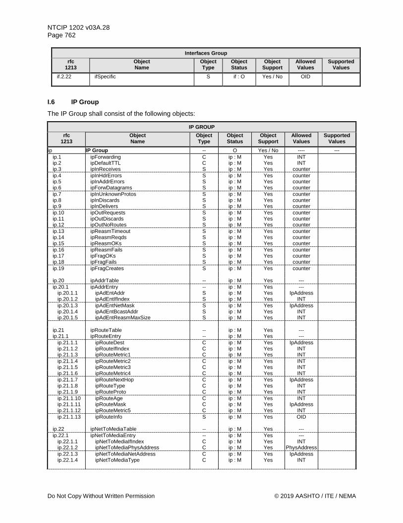
NTCIP 1202 v03A.28 Page 762
Do Not Copy Without Written Permission © 2019 AASHTO / ITE / NEMA
Interfaces Group rfc
1213 Object Name
Object Type
Object Status
Object Support
Allowed Values
Supported Values
if.2.22 ifSpecific S if : O Yes / No OID
I.6 IP Group The IP Group shall consist of the following objects:
IP GROUP rfc
1213 Object Name
Object Type
Object Status
Object Support
Allowed Values
Supported Values
ip IP Group -- O Yes / No ---- --- ip.1 ipForwarding C ip : M Yes INT ip.2 ipDefaultTTL C ip : M Yes INT ip.3 ipInReceives S ip : M Yes counter ip.4 ipInHdrErrors S ip : M Yes counter ip.5 ipInAddrErrors S ip : M Yes counter ip.6 ipForwDatagrams S ip : M Yes counter ip.7 ipInUnknownProtos S ip : M Yes counter ip.8 ipInDiscards S ip : M Yes counter ip.9 ipInDelivers S ip : M Yes counter ip.10 ipOutRequests S ip : M Yes counter ip.11 ipOutDiscards S ip : M Yes counter ip.12 ipOutNoRoutes S ip : M Yes counter ip.13 ipReasmTimeout S ip : M Yes counter ip.14 ipReasmReqds S ip : M Yes counter ip.15 ipReasmOKs S ip : M Yes counter ip.16 ipReasmFails S ip : M Yes counter ip.17 ipFragOKs S ip : M Yes counter ip.18 ipFragFails S ip : M Yes counter ip.19 ipFragCreates S ip : M Yes counter
ip.20 ipAddrTable -- ip : M Yes --- ip.20.1 ipAddrEntry -- ip : M Yes ---
ip.20.1.1 ipAdEntAddr S ip : M Yes IpAddress ip.20.1.2 ipAdEntIfIndex S ip : M Yes INT ip.20.1.3 ipAdEntNetMask S ip : M Yes IpAddress ip.20.1.4 ipAdEntBcastAddr S ip : M Yes INT ip.20.1.5 ipAdEntReasmMaxSize S ip : M Yes INT
ip.21 ipRouteTable -- ip : M Yes --- ip.21.1 ipRouteEntry -- ip : M Yes ---
ip.21.1.1 ipRouteDest C ip : M Yes IpAddress ip.21.1.2 ipRouteIfIndex C ip : M Yes INT ip.21.1.3 ipRouteMetric1 C ip : M Yes INT ip.21.1.4 ipRouteMetric2 C ip : M Yes INT ip.21.1.5 ipRouteMetric3 C ip : M Yes INT ip.21.1.6 ipRouteMetric4 C ip : M Yes INT ip.21.1.7 ipRouteNextHop C ip : M Yes IpAddress ip.21.1.8 ipRouteType C ip : M Yes INT ip.21.1.9 ipRouteProto C ip : M Yes INT ip.21.1.10 ipRouteAge C ip : M Yes INT ip.21.1.11 ipRouteMask C ip : M Yes IpAddress ip.21.1.12 ipRouteMetric5 C ip : M Yes INT ip.21.1.13 ipRouteInfo S ip : M Yes OID
ip.22 ipNetToMediaTable -- ip : M Yes --- ip.22.1 ipNetToMediaEntry -- ip : M Yes ---
ip.22.1.1 ipNetToMediaIfIndex C ip : M Yes INT ip.22.1.2 ipNetToMediaPhysAddress C ip : M Yes PhysAddress ip.22.1.3 ipNetToMediaNetAddress C ip : M Yes IpAddress ip.22.1.4 ipNetToMediaType C ip : M Yes INT

NTCIP 1202 v03A.28 Page 763
© 2019 AASHTO / ITE / NEMA Do Not Copy Without Written Permission
IP GROUP rfc
1213 Object Name
Object Type
Object Status
Object Support
Allowed Values
Supported Values
ip.23 ipRoutingDiscards S ip : M Yes counter
I.7 ICMP Group The ICMP Group shall consist of the following objects:
ICMP GROUP rfc
1213 Object Name
Object Type
Object Status
Object Support
Allowed Values
Supported Values
icmp ICMP Group -- O Yes / No ---- --- icmp.1 icmpInMsgs S icmp : M Yes counter icmp.2 icmpInErrors S icmp : M Yes counter icmp.3 icmpInDestUnreachs S icmp : M Yes counter icmp.4 icmpInTimeExcds S icmp : M Yes counter icmp.5 icmpInParmProbs S icmp : M Yes counter icmp.6 icmpInSrcQuenchs S icmp : M Yes counter icmp.7 icmpInRedirects S icmp : M Yes counter icmp.8 icmpInEchos S icmp : M Yes counter icmp.9 icmpInEchoReps S icmp : M Yes counter icmp.10 icmpInTimestamps S icmp : M Yes counter icmp.11 icmpInTimestampReps S icmp : M Yes counter icmp.12 icmpInAddrMasks S icmp : M Yes counter icmp.13 icmpInAddrMaskReps S icmp : M Yes counter icmp.14 icmpOutMsgs S icmp : M Yes counter icmp.15 icmpOutErrors S icmp : M Yes counter icmp.16 icmpOutDestUnreachs S icmp : M Yes counter icmp.17 icmpOutTimeExcds S icmp : M Yes counter icmp.18 icmpOutParmProbs S icmp : M Yes counter icmp.19 icmpOutSrcQuenchs S icmp : M Yes counter icmp.20 icmpOutRedirects S icmp : M Yes counter icmp.21 icmpOutEchos S icmp : M Yes counter icmp.22 icmpOutEchoReps S icmp : M Yes counter icmp.23 icmpOutTimestamps S icmp : M Yes counter icmp.24 icmpOutTimestampReps S icmp : M Yes counter icmp.25 icmpOutAddrMasks S icmp : M Yes counter icmp.26 icmpOutAddrMaskReps S icmp : M Yes counter
I.8 A.33 TCP Group The TCP Group shall consist of the following objects:
TCP GROUP rfc
1213 Object Name
Object Type
Object Status
Object Support
Allowed Values
Supported Values
tcp TCP Group -- O Yes / No ---- --- tcp.1 tcpRtoAlgorithm S tcp : M Yes INT tcp.2 tcpRtoMin S tcp : M Yes INT tcp.3 tcpRtoMax S tcp : M Yes INT tcp.4 tcpMaxConn S tcp : M Yes INT tcp.5 tcpActiveOpens S tcp : M Yes counter tcp.6 tcpPassiveOpens S tcp : M Yes counter tcp.7 tcpAttemptFails S tcp : M Yes counter tcp.8 tcpEstabResets S tcp : M Yes counter tcp.9 tcpCurrEstab S tcp : M Yes counter tcp.10 tcpInSegs S tcp : M Yes counter tcp.11 tcpOutSegs S tcp : M Yes counter tcp.12 tcpRetransSegs S tcp : M Yes counter tcp.13 tcpConnTable -- tcp : M Yes ---

NTCIP 1202 v03A.28 Page 764
Do Not Copy Without Written Permission © 2019 AASHTO / ITE / NEMA
TCP GROUP rfc
1213 Object Name
Object Type
Object Status
Object Support
Allowed Values
Supported Values
tcp.13.1 tcpConnEntry -- tcp : M Yes --- tcp.13.1.1 tcpConnState C tcp : M Yes INT tcp.13.1.2 tcpConnLocalAddress S tcp : M Yes IpAddress tcp.13.1.3 tcpConnLocalPort S tcp : M Yes INT tcp.13.1.4 tcpConnRemAddress S tcp : M Yes IpAddress tcp.13.1.5 tcpConnRemPort S tcp : M Yes INT
tcp.14 tcpInErrs S tcp : M Yes counter tcp.15 tcpOutRsts S tcp : M Yes counter
I.9 A.34 UDP Group The UDP Group shall consist of the following objects:
UDP GROUP rfc
1213 Object Name
Object Type
Object Status
Object Support
Allowed Values
Supported Values
udp UDP Group -- O Yes / No ---- --- udp.1 udpInDatagrams S udp : M Yes INT udp.2 udpNoPorts S udp : M Yes INT udp.3 udpInErrors S udp : M Yes INT udp.4 udpOutDatagrams S udp : M Yes INT udp.5 udpTable -- udp : M Yes ---
udp.5.1 udpEntry -- udp : M Yes --- udp.5.1.1 udpLocalAddress S udp : M Yes IpAddress udp.5.1.2 udpLocalPort S udp : M Yes INT
I.10 A.35 Ethernet Group The Ethernet Group shall consist of the following objects:
Ethernet Group rfc
1643 Object Name
Object Type
Object Status
Object Support
Allowed Values
Supported Values
dot3 Ethernet Group -- O Yes / No ---- --- dot3.2 dot3StatsTable -- dot3 : M Yes --- --- dot3.2.1 dot3StatsEntry -- dot3 : M Yes --- ---
dot3.2.1.1 dot3StatsIndex S dot3 : M Yes INT dot3.2.1.2 dot3StatsAlignmentErrors S dot3 : M Yes counter dot3.2.1.3 dot3StatsFCSErrors S dot3 : M Yes counter dot3.2.1.4 dot3StatsSingleCollisionFrames S dot3 : M Yes counter dot3.2.1.5 dot3StatsMultipleCollisionFrames S dot3 : M Yes counter dot3.2.1.6 dot3StatsSQETestErrors S dot3 : M Yes counter dot3.2.1.7 dot3StatsDeferredTransmissions S dot3 : M Yes counter dot3.2.1.8 dot3StatsLateCollisions S dot3 : M Yes counter dot3.2.1.9 dot3StatsExcessiveCollisions S dot3 : M Yes counter dot3.2.1.10 dot3StatsInternalMacTransmitErrors S dot3 : M Yes counter dot3.2.1.11 dot3StatsCarrierSenseErrors S dot3 : M Yes counter dot3.2.1.13 dot3StatsFrameTooLongs S dot3 : M Yes counter dot3.2.1.16 dot3StatsInternalMacReceiveErrors S dot3 : M Yes counter dot3.2.1.17 dot3StatsEtherChipSet S dot3 : M Yes OID
dot3.5 dot3CollTable -- dot3 : O Yes / No dot3.5.1 dot3CollEntry -- dot3 : O Yes / No
dot3.5.1.2 dot3CollCount S dot3 : O Yes / No INT dot3.5.1.3 dot3CollFrequencies S dot3 : O Yes / No counter
dot3.6 dot3Tests -- dot3 : O Yes / No dot3.6.1 dot3TestTdr S dot3 : O Yes / No dot3.6.2 dot3TestLoopBack S dot3 : O Yes / No

NTCIP 1202 v03A.28 Page 765
© 2019 AASHTO / ITE / NEMA Do Not Copy Without Written Permission
Ethernet Group rfc
1643 Object Name
Object Type
Object Status
Object Support
Allowed Values
Supported Values
dot3.7 dot3Errors -- dot3 : O Yes / No dot3.7.1 dot3ErrorInitError S dot3 : O Yes / No dot3.7.2 dot3ErrorLoopbackError S dot3 : O Yes / No
§


![Understanding the Security of Traffic Signal InfrastructureHighway and Transportation Officials (AASHTO) [5], Institute of Transporta-tion Engineers (ITE) [22], and National Electrical](https://static.fdocuments.net/doc/165x107/605510fb79d8c241df05dc82/understanding-the-security-of-traffic-signal-highway-and-transportation-oifcials.jpg)