A IM-integrated approach to onstruction Quality Management
79
A BIM-integrated approach to Construction Quality Management Enabling information and knowledge management during the execution phase of a project lifecycle Graduation thesis by: E. (Esper) Achkar Faculty and Program: Construction Management & Engineering (2016)
Transcript of A IM-integrated approach to onstruction Quality Management

A BIM-integrated approach to Construction Quality Management
Enabling information and knowledge management during the execution phase of a project lifecycle
Graduation thesis by: E. (Esper) Achkar
Faculty and Program: Construction Management & Engineering (2016)

Page 1 of 79
Colophon
Title: A BIM-Integrated approach to construction quality management Subtitle: Enabling information and knowledge management during the execution phase of a project life cycle Author: Esper Achkar University Identification Number: 0923243 Email: [email protected] University: Eindhoven University of Technology Graduation program: Master of Construction Management and Engineering Graduation Committee: Prof.dr.ir. B.(Bauke) De Vries University supervisor (chairman graduation committee) Dr.dipl.ing. J. (Jakob) Beetz University Supervisor Ir. T.F (Thomas) Krijnen University Supervisor Ir. W.J. (Joost) van de Koppel Hendriks Bouw & Ontwikkeling (External Supervisor) Thesis Defense Date: December 8th , 2016

Page 2 of 79
Preface It is with great pleasure that I present this thesis as a result of my graduation project. The research is conducted with the supervision of the Eindhoven University of Technology and Hendriks Bow en Ontwikkeling firm. The results in this thesis are the product of support, guidance and collaboration of many people who believed in the research question(s) importance and relevance to the construction engineering community. I had the opportunity to work with academics, who provided insight and critical questions during the development of the thesis, provoking me to think “out of the box” or look at the problem from different angles. I also had the privilege of collaborating with construction professionals in the Dutch industry, who provided valuable opinion and information that was vital in developing the idea from a theoretical framework into a working prototype, taking into consideration the existing industry practices. I would like to thank my university supervisor Jakob Beetz for his guidance throughout the thesis. His remarks after every meeting helped me refine the idea and its scope, ensuring that the roadmap and objectives were adhered to. I also appreciate the degree of freedom and trust given to me by him, allowing me to take ownership of the outcomes, and for his optimism throughout the course of the study, which reassured me through the stressful times that were encountered in the process. Special thanks to my second supervisor, Thomas Krijnen who supported me in developing the framework into a functional prototype. He was always responsive to my technical questions regarding software development, patiently explaining concepts rather than providing simple solutions, which helped me develop an appreciation for the field of computer sciences. Along with Jakob, He always provided thoughtful remarks on the direction of the developed application and ways to improve its functionality. I would also like to thank Joost Van de Koppel for his support in providing: feedback on the developed application, developing the necessary deliverables that were missing for the application to function with the help of his colleagues, access to company data for research purposes and most importantly his result driven attitude and genuine interest in the project, which motivated me to deliver the results. I would like to finally thank my family for their support during my studies, I look back their encouragement during these times and feel proud and thankful of having such support. Esper Achkar November, 2016

Page 3 of 79
Table of Contents Colophon ...................................................................................................................................................... 1
Preface .......................................................................................................................................................... 2
Summary ....................................................................................................................................................... 5
Abstract ........................................................................................................................................................ 7
1. Introduction .............................................................................................................................................. 9
1.1 Problem definition .............................................................................................................................. 9
1.2 Research questions(s) ....................................................................................................................... 10
1.3 Research design ................................................................................................................................ 11
1.4 Expected results ................................................................................................................................ 11
2. Glossary .................................................................................................................................................. 13
3. Literature review .................................................................................................................................... 15
3.1 Defects – Nature and Characteristics .............................................................................................. 15
3.2 Current quality management practices ........................................................................................... 19
3.2.1 Project Quality Management ................................................................................................... 19
3.2.2 Construction Quality Management .......................................................................................... 21
3.3 The Dutch Quality Directive (Kwaliteitborging) .............................................................................. 25
3.4 BIM and quality management ......................................................................................................... 27
3.5 Summary of Literature review ......................................................................................................... 30
4. Model ...................................................................................................................................................... 32
4.1 Introduction ...................................................................................................................................... 32
4.2 Method ............................................................................................................................................. 33
4.2.1 BIM integrated quality management plan overview .............................................................. 33
4.2.2 Quality Control System overview ............................................................................................. 35
4.2.3 Quality Assurance System overview ......................................................................................... 42
4.3 Results ............................................................................................................................................... 44
4.3.1 Section Introduction .................................................................................................................. 44
4.3.2 Latent defects Statistics ............................................................................................................ 45
4.3.3 Project deliverables ................................................................................................................... 48
4.3.4 The Quality Management Framework ..................................................................................... 55
4.3.5 Pilot Project Data collection...................................................................................................... 64
................................................................................................................................................................ 67
4.4 Discussion ......................................................................................................................................... 67
5. Conclusion .............................................................................................................................................. 71

Page 4 of 79
5.1 Scientific Relevance .......................................................................................................................... 71
5.2 Societal Relevance ............................................................................................................................ 71
References .................................................................................................................................................. 73
Appendix A.................................................................................................................................................. 76
Appendix B .................................................................................................................................................. 76
Appendix C .................................................................................................................................................. 76
Appendix D ................................................................................................................................................. 77
Appendix E .................................................................................................................................................. 77
Appendix F .................................................................................................................................................. 77
Table of Figures Figure 1: Reasons for poor quality onsite (Rumane, 2011) ........................................................................ 17
Figure 2: The project management triangle (Rumane, 2011)..................................................................... 19
Figure 3: project quality management dynamics (Rose, 2005) .................................................................. 21
Figure 4: Role interaction in DBB projects (Rumane, 2011) ....................................................................... 22
Figure 5: Quality management pyramid (Rumane, 2011) .......................................................................... 23
Figure 6: PDCA cycle for construction projects (Rose, 2005) ...................................................................... 25
Figure 7: The integrated quality management plan overview .................................................................... 33
Figure 8: process overview of proposed quality management plan .......................................................... 35
Figure 9: Structure of QC system ................................................................................................................ 37
Figure 10: QC analysis flow chart ................................................................................................................ 38
Figure 11: Conditional requirements .......................................................................................................... 38
Figure 12: The process and product prerequisite mapping schema .......................................................... 40
Figure 13: QC System results/output .......................................................................................................... 41
Figure 14: QA system Input/output ............................................................................................................ 43
Figure 15: Layout of Phase 1 & 2 of Hutgraaf project ................................................................................. 48
Figure 16: The Hutgraaf project (Phase 2) – Tekla BIMsight ...................................................................... 49
Figure 17: creating the Ifc model with 4D attributes .................................................................................. 50
Figure 18: Quality management framework (QA and QC) structure .......................................................... 56
Figure 20: XML Schema of the project schedule ........................................................................................ 57
Figure 21: Inspections, elements and quality checks (tables) from the database ..................................... 59
Figure 22: QA User interface (Webpage) .................................................................................................... 60
Figure 23: Interactive element locator ....................................................................................................... 60
Figure 24: Result table after submission ..................................................................................................... 61
Figure 25: Color coded model – Rejected quality inspection example of a window .................................. 62
Figure 26: Imported BCF report .................................................................................................................. 63
Figure 27: Quality inspections overview ..................................................................................................... 65
Figure 28: Quality KPI over time period ...................................................................................................... 66
Figure 29: Comments recorded for rejected inspections ........................................................................... 66
Figure 30: Mockup Quality Management Dashboard ................................................................................ 67
Page 5 of 79
Summary
Quality defects on construction projects have long been a subject of interest, and paradoxically, a nuisance for construction professionals in particular, and the architecture, engineering and construction (AEC) community in general. Quality related issues during the construction phase of the project lifecycle are notorious for being costly to amend both in direct monetary terms and schedules delays that result from it. Quality defects also create additional hidden costs and inconveniences during the operation & maintenance (O&M) phase of projects in the form of latent defects if not detected early on. The engineering industry has therefore been keen to understand the occurrences, impact, nature and root causes of construction quality defects. Research on quality defect mitigation has also gathered momentum in recent years, promising solutions that reduce costs, optimize the construction process and deliver a project of higher quality. The most notable development that has taken place in recent years within the AEC industry is the rapid improvements to Building Information Modeling (BIM), which has optimized the collaboration between various engineering systems and disciplines during the preliminary and detailed design phase of the project lifecycle, producing less error-prone and robust design. The adoption of BIM by the construction industry has helped in reducing the frequency of quality defect issues. However, recent studies (Rosenfeld & Ben-Oz, 2004) (Ahzahar, Karim, S.H, & Eman, 2011) indicate that defects are still a common occurrence on projects, indicating that the design phase is not solely responsible for quality issues on construction sites. This has led to another development to gather pace more recently in the hopes of stemming quality issues on projects: the implementation of automation in construction quality control systems, focusing on tools such as laser scanners (point cloud data) and augmented reality to support automated decision making processes. The tools have promising potential, but have several shortcomings mentioned by the research community such as high barriers to entry (costs), high level of technical operational competence. Most importantly, they are based on an (probably unrealistic) assumption, that poor supervision during on-site inspections due to flawed decision making processes is the main cause of quality defects. Research points to another important cause among others, which combined with poor supervision, leads to quality defects: site information management. Poor information management manifests in several forms on the construction site: as delayed communication between stakeholders (feedback and feedforward loops), misunderstandings due to incorrect drawing versions and specification interpretations, and data loss. The latter issue can be mitigated by incorporating a methodology for efficiently recording, retrieving and analyzing quality related data. The usefulness of integrating BIM (and more specifically 4-D BIM) concepts into current construction quality management frameworks in order to optimize information management and provide a robust methodology to handle quality related data (knowledge management) has only recently been explored. These developments however, have continued to follow the pitfalls of previous research, which neglects the influence of proper knowledge management in refining the quality-related processes and overstate the importance of automated decision making approaches. This thesis attempts to incorporate BIM concepts in order to optimize information

Page 6 of 79
and knowledge management of current construction quality management plans through a proposed theoretical framework encompassing all divisions of the management plan: Quality Assurance, Quality Control and Communication Protocols. The thesis complements the proposed theoretical framework by providing a prototypical software tool implementation that demonstrates the practical application of the framework. The advantages and practicality of the prototypical application are highlighted through demonstrations on a pilot project in the Netherlands. The scope of the developed tool was determined by collecting and examining data regarding logged complaints of defects by clients over several years after hand over of projects (Latent defects). This approach was used to limit the developed application’s functionality to defects that have the highest frequency of occurrence, establishing the tool as a “proof-of-concept” rather than a complete solution. This is due to several limitations, an important one being that the quality management plans and inspection procedures (checklists) are not standardized to an industry level in the Netherlands. Therefore, several necessary deliverables necessary for the tool to function were needed to be developed with the help of construction professionals:
Predefined list of inspection requirements (checklist) for the elements under consideration
A mapped list of possible defects/comments for each inspection item
The pre-conditional requirements that trigger the inspections. Pre-conditional requirements determine at what point in the project progress is an inspection for an element required (process) and which inspection/requirement is necessary for the concerned element based on its properties (product)
The developed application analyzes the deliverables and determines the relevant quality requirements that need to be conducted on the construction site based on the project progress. The application also provides a user interface where these inspections are displayed to the user in order to facilitate displaying the results as well as provide a platform to register and document the inspection results by the user. The application provide immediate feedback regarding the results of the inspections, so that necessary action can take place. The application ensures that each step in the process is documented, creating a knowledge management system that can retrieved and analyze quality related metrics, allowing insight into current processes, highlight inefficiencies and provide a basis for improvements in quality management plans. The limitations and biases of the research are also discussed, as well as suggestions to mitigate their influence, providing further research opportunities in this field of study.

Page 7 of 79
Abstract The research paper proposes an integrated quality management framework that incorporates Building Information Modeling (BIM) concepts, in order the reduce quality defect occurrences on construction projects. Reducing quality defects on construction projects improves resource utilization, reduces overall costs and project delays, and increases the overall quality of delivered projects. The paper highlights the weaknesses of current construction management practices as well as previous developments of integrating BIM into quality management plans through an extensive literature review. The suggested framework encompasses the core concepts of quality management: quality control, quality assurance and communication protocol. The framework is developed into a working prototype to demonstrate the advantages of this approach. Data collected of quality complaints over several years reinforce the paper’s hypotheses and limits the scope of the developed framework. Meetings with construction professionals in the Dutch industry were conducted in order to receive feedback and develop the quality requirements and the process & product conditional triggers necessary for a quality requirement to take place. The framework utilizes Information Foundation Class (IFC) BIM models and construction schedules along with the previous deliverables in order to generate the desired results. The system was tested on a pilot construction project in the Netherlands, where the full potential of the approach was realized. The findings of the paper serve as an attempt to provide a comprehensive quality management framework that can be adopted within current construction practice guidelines, as well as highlight the advantages of research in this field of study.

Page 8 of 79

Page 9 of 79
1. Introduction
1.1 Problem definition One of the most troublesome, and often neglected, issues that the Architectural, Engineering and Construction (AEC) industry faces during the execution phase of a project is quality defects. Defects are considered by many construction professionals as a certainty rather than an avoidable occurrence due to the misunderstanding and ambiguity that surrounds it: quality defects are often attributed to poor workmanship or inadequate site supervision. The idea that current construction quality management practices are ineffective in dealing with the increased complexity of construction projects is an idea that has recently gained momentum, although skepticism over the inadequacy of construction quality management persists: it is argued that project quality management is a broad discipline that encompasses several industries (manufacturing, services etc.) that have a proven track record of reducing defects and boosting production efficiency. One of the reasons that this claim is rarely challenged is due to the construction industry’s poor record keeping and knowledge management (KM) practices: project documentation is complex and bureaucratic, involves many stakeholders and is rarely used as a learning tool for future project planning (“lessons learned”). Several studies have collected and analyzed quality related data on construction sites: the results indicate that even though poor workmanship is usually the main root cause of on-site defects (45%), poor management practices accounted for as much as 19% of the defect root causes (Rosenfeld & Ben-Oz, 2004). The study also raised concerns on the quality management practices’ effectiveness: 67% of all quality defects were discovered during the delivery stage of the project, 20% of the defects were discovered by tenants after hand over and quality inspectors were only able to identify 3 % of the deficiencies during construction. Therefore, the theoretical objective of the thesis is to: “Realize modified quality practices and tools that reduce construction quality defects” The literature review’s findings indicate that project quality management practices that are implemented in other industries effectively do not provide the same effects on the construction industry. The need for a new approach for quality management practices that addresses the unique nature of quality defects and mitigates their effects in the construction industry is gaining momentum. Defects in the construction industry differ compared to other industries since: projects are unique and therefore construction activities are seldom repetitive in nature (from a controlled environment perspective), quality defect data is not zealously collected as other industries which makes corrective decision making difficult, and organizational structures are hierarchical and strictly defined, increasing the time required to transfer of information between stakeholders. The thesis aims to explore possible improvements and refinements to traditional project quality management practices in order to reduce quality defects through addressing the root causes of quality defects and the limitations of the construction quality management practices/applications. In order to achieve the theoretical objective of the thesis, the following question must be asked and answered: “How can current construction quality management practices’ limitations be mitigated to reduce on-site defects?”

Page 10 of 79
1.2 Research questions(s) The defined problems of the thesis cannot be answered directly, but rather through several research questions which will be answered partly through the literature review and theoretical research, while other questions will be answered through practical approach which would involve a new proposed framework for construction quality management practices. The research questions that will be addressed in order to answer the thesis problem definitions are:
What are the weaknesses and limitations of the current quality management practices and what are the root causes of these limitations? This question will be addressed through research (literature review on the nature of defects), as well as through a practical approach of collecting recorded data from several projects in the Dutch construction industry. The result of answering this question will lead to a well-defined list of limitations and their root causes.
What are the current tools available to mitigate the limitations of current construction quality practices? What attempts have been made in this aspect? This question is addressed by research into the literature of quality management enhancement and the role BIM plays within it. The results of answering this question will provide validation of the effectiveness of BIM implementation in mitigating the issues of current quality management practices, as well as identifying the limitations with the current attempts made.
How can BIM-integrated quality control approaches incorporate checks for the processes that lead to the completed component? This question is addressed by understanding the current approaches to quality control based on industry standards. Based on the literature, a BIM-integrated quality control (QC) system that mitigates the limitations specific to the construction quality control practices is proposed. The framework will be developed into a tool as part of the validation process.
How can quality control results and knowledge management become incorporated, using BIM, in order to enhance the quality assurance practices on site, gauge performance and provide “lessons learned” for future projects? This question is addressed by proposing a BIM-integrated quality assurance (QA) system that mitigates the limitations specific to the construction quality assurance practices. The framework will be developed into a tool as part of the validation process.
What communication mechanisms are needed allow quality control practices to adapt, based on feedback from quality KPIs on a project? How will the integrated framework regulate information exchange (enter input/receive output) between the stakeholders, at different stages of the quality control and quality process? This question is addressed by determining the current informational exchange protocols/standards based on construction quality management literature. Based on that output, the QA and QC tools are enhanced to provide data extraction and manipulation capabilities. The end result would be a modified information exchange protocol that incorporates the QA and QC tools.

Page 11 of 79
1.3 Research design The research is divided into two main parts: research involving a thorough literature review, and a framework application development. The research questions are addressed with the academic review and study of the available literature in order to: validate the main hypotheses of the thesis paper regarding quality defects and their effect on the construction industry, as well as to highlight the need for innovation in this field. The literature review will also explore research that has been conducted in this field of study and the weaknesses of these approaches, which will serve as a guide to the proposed quality management framework of this research paper. The findings will serve as a basis for the formulation of the theoretical framework and its mechanism. The development part proposes a BIM-integrated quality management framework based on the results of the research and literature review. The process begins with analyzing the collected data of recorded defects on construction sites in the Netherlands. The aim of analyzing the collected data is to:
Add empirical validation to the hypotheses that defects are still a common occurrence on construction sites and cause cost overruns, schedule delays and loss of productivity
Identify the root causes that construction professionals perceive as the causes of defects, which will be compared to the literature review findings.
Provide a scope to the development of the proposed quality management framework by identifying which engineering discipline construction professionals have difficulties with (ie. in which engineering discipline do most of the defects occur on-site?)
The collected data and results of the literature study are used as a basis for proposing a BIM integrated quality management framework. The theoretical framework is implemented into a standalone, prototypical software tool which is used on a pilot project BIM model in order to demonstrate the potential of practically implementing the proposed quality management. A pilot project has implemented the new quality management framework for the duration of 4 weeks, during which the frequency of quality defects was recorded and compared to conventional quality management approaches on projects of similar characteristics. The paper discusses these findings and results, its shortcomings and provide recommendations for future research on the topic.
1.4 Expected results The results and objectives of the proposed research into a BIM integrated QM framework would:
Provide a methodology to reduce the amount of defects, direct or latent, that occur during the construction phase of a project through improved quality management practices, thus improving efficiency and reducing costs
Provide a mechanism to store, retrieve and analyze collected project data
Retain quality performance results (KPI) that can be used to improve current quality management practices on site as well as future projects of the same size and character

Page 12 of 79
Improve the communication and information sharing practices between the stakeholders through feedback and feedforward loops in the framework: this eliminates defects that take place due to misunderstandings and outdated project information
The research’s secondary objective is to hopefully draw attention to a phase in the construction project lifecycle that is currently overlooked by the BIM community: the execution phase of the project. Research has been fragmented in this field with attempts to create tools that solve problems in particular areas in the construction process, such as automated construction scheduling, as-built measurement through scanners and data mining techniques. Previous research however, has not attempted to provide complete BIM integrated solutions to the construction industry in field of quality management. This research is a first attempt to provide a comprehensive solution for on-site quality management, which would hopefully encourage more research in the future into this interesting topic.

Page 13 of 79
2. Glossary 0-9
4-D Model An acronym for 4-D BIM, a term that refers to the intelligent linking of individual 3D components or assemblies with time- or schedule related information
B
Building Information Modeling (BIM)
A process involving the generation and management of exchangeable digital representations of physical and functional characteristics of places
BIM Collaborative Format (BCF)
An open XML format that supports workflow communication in BIM processes
C
Collaborative Design Activity (Collada)
An open standard XML schema for exchanging digital assets among various graphic software applications. Adopted by ISO as a publicly available specification (ISO 17506)
Communication protocol
The mechanism by which the various divisions of the quality management framework interact together, exchanging data in the process
G
Global Unique Identifier (GUID)
A unique reference number used as an identifier to uniquely distinguish entities in computer software. It is typically stored in 128-bit hexadecimal encoding
I
Information management
The acquisition of information from one or more sources, the custodianship and the distribution of that information to those who need it, and it’s ultimate disposition through archiving and deletion
Industry Foundation Classes ( IFC)
A platform neutral, open object-based file format specification developed by BuildingSMART to facilitate the interoperability of the AEC industry. It is commonly used as a collaborative tool in the AEC industry
K
Knowledge management
Refers to the process by which data is stored, retrieved and manipulated in order to achieve organizational objectives by making the best use of the available information
L
Latent defects A fault in the property of an project element that is caused by failures in design, workmanship or materials, that may not be detectable directly after production
M
Mapping Scheme A contextual relationship between two or more entities, and their characteristics
P
Process conditional Requirements
The elements relating to the scheduled activities, and their state, by which a quality requirement is needed to be conducted

Page 14 of 79
Product conditional Requirements
The physical objects, and their associated properties, that triggers a quality requirement to be conducted
Q
Quality Assurance System
A division of quality management that deals with receiving input from quality control practices, quantify and analyze these inputs to determine if overall project metrics are within acceptable guidelines, and provide feedback or corrective measures when necessary
Quality Control System
A division of quality management that deals with the monitoring of project elements to ensure that these entities are produces according to the acceptable quality requirements
Quality requirements A set of agreed upon standards that project elements must adhere to in order to be deemed “fit for use” (specifications)
R
Relational model (RM) An approach to managing data using structure and language consistent with first-order predicate logic
Referential integrity A property of data which, when satisfied, requires a value of one attribute of a relation to exist as a value of another attribute in a different (or same) relation
Relational Databases A database whose organized based on the relational model of data
S
Scalable Vector Graphics (SVG)
An XML based open standard developed by the world wide web consortium (W3C) for vector imaging format for two dimensional graphics
W
Work Breakdown Structure (WBS)
A deliverable-oriented decomposition of a project activities into smaller components, organizing work into manageable sections
X
Extensible Markup Language (XML)
A markup language that defines a set of rules for encoding documents in a format that is both human and machine readable, developed into a specification (1.0) by world wide web consortium (W3C)

Page 15 of 79
3. Literature review 3.1 Defects – Nature and Characteristics Construction projects aim to deliver a product to a client based on a set of nationally/internationally accepted standards of quality, called specifications, set by the client or technical representatives within the scope, budget and schedule agreed upon with the stakeholders involved. Standards of quality however, although well documented, do not eliminate the risk of quality issues such as defects to occur on construction projects. Construction specifications are still largely paper-based , even though they are prepared electronically, since they are considered as part of the contract which needs to be signed by the involved parties in order to legally bind a contractor to an agreed upon quality and to clearly state what the client considers an acceptable result (Bauch & Bargstadt, 2015). Defects are the result of activities being performed incorrectly, creating cost overruns due to resources being allocated in order to perform rework activities (Alwi, Hampson, & Mohamed, 2002) as well as causing schedule delays. (Josephson & Hammarlund, 1999) argue that improper understanding of the standards, poor workmanship, poor planning and coordination of resources and poor supervision and control are the main internal factors for quality defects during the construction phase of a project. Other causes for defects on site are due to external factors such as change orders and unforeseen site conditions. Change orders usually are initiated by the client or his consultant design team but can also be initiated by the contractor to propose ideas for better quality while at the same time improving their cost/price ratio (Bargstadt, 2014). Another consequence of poor quality are latent defects, which do not appear until later when projects are complete and operational. Latent defects are more difficult to detect and are caused by design, specification, material or managerial errors (Chong & Low, 2006). The cost associated with defects, both direct and latent, has been studied extensively: The costs of defects account for 4% of the contract value, on average, in residential building (Mills, Love, & Williams, 2009) worldwide, while (Love & Li, 2000) estimated the defects to account for 3.15% and 2.14% for residential and industrial buildings, respectively. Research that has also been conducted by the Construction Industry Institute (CII) revealed that the average cost of defect reworks on construction projects is approximately 5% of the construction costs (CII, 2005) in the United States. Although the incurred costs of poor quality may appear to be similar, there are four categories of costs that result from poor quality (Rumane, 2011):
Internal failure costs: The costs associated with defects found before a product is delivered to a customer. These costs are incurred after internal QC inspections on site
External failure costs: The costs associated with defects found after the customer receives their product. These costs are due to latent defects that were not detected through construction quality management practices
Appraisal costs: The costs incurred to determine the degree of conformance to quality requirements.
Prevention costs: The costs incurred to keep failure and appraisal to a minimum To varying degrees, the source of poor quality costs are usually attributed to a combination of these four costs categories being incurred on a given construction project.

Page 16 of 79
It is therefore clear that quality defects are a concern for construction projects and their elimination, or minimization, would increase the efficiency and reduce cost overruns and schedule delays. This has led to the further investigation into the causes of defects (causation analysis) on construction projects. Over the last decade, numerous studies on defect causation analysis and management systems have been conducted to facilitate defect measures and rectifications as well as to reduce the reoccurrence of the defect (Palaneesewaran, 2006). The studies can be classified into four major categories: (1) identifying causation of defects and analyzing its impact, (2) collecting and classifying defect data, (3) searching and managing defect information related to knowledge management (KM) and (4) developing defect control system on the construction site. Causes of defects have been found to vary on a project-basis, but the major reason behind their occurrence is due to documentation errors (Cusak, 1992). Studies have also found that most of the design-related defects that occurred on construction projects were related to poor managerial practices of architectural firms (Rounce, 1998). Specifications for various components are also produced at various locations, with different calculation tools and sometimes with different analyzing models, increasing the risk of potential contradictions in the understanding of specifications (Hollermann & Bargstadt, 2014). Better understanding of the causes of quality defects on construction projects led to important recommendations and guidelines for mitigating their occurrence, as part of an improved Quality Management Plans (QMP). Literature indicates that the specification documents themselves are comprehensive and not the direct cause of quality defects. Information management on site however, is underdeveloped and causes many of the quality defects taking place on construction projects. The causes of on-site quality management issues have been examined closely over the years, with field inspection practices identified as the main contributor to on-site defects. The following are the weaknesses/issues in current field inspection practices (Lee, 2012):
Workload: inspections require complex analysis skills on behalf of the inspector because of the manual and physical inspection work, which consists of complicated tasks due to lots of components, spaces, objects, and construction methods being checked
Data loss: the procedures of re-inputting defect information that have already been recorded in shop drawings or papers at the site are wasteful. Moreover, it is often the case to omit and miswrite some valuable defect data during the re-input
Reactive approach: Most of the tools used on-site by the stakeholders involved are used after a defect has taken place. It is usually the case that correction at this stage has the highest cost and time impact on the project

Page 17 of 79
Figure 1: Reasons for poor quality onsite (Rumane, 2011)
Based on these weaknesses, several important recommendations have been made in order to enhance the current quality management processes on construction projects. Causation analysis of defects have been found to be less effective if not properly integrated into a developed feedback and feedforward knowledge networking system (Palaneesewaran, 2006), indicating that a proactive approach to site information in quality management is key in improving current practices. The collection and classification of data into a rework data collection system was also proposed in order to measure defect data quantitatively on the basis of cost, schedule and other impacts which include detailed defect categories. (Josephson, Larsson, & Li, 2002). Another interesting observation and recommendation is that although great efforts have been made in the knowledge management (KM) systems relating to project problems and solutions (know-how), there is a great difficulty in capturing and reusing the project knowledge within current construction practices (Tan, Anumba, & et. al, 2007). The major obstacle that users face is that they cannot easily find project-related knowledge or do not know what accumulated knowledge is available (Lin, Wang, & et. al, 2006). This indicates that there is a need for real-time access, data organization and querying capabilities in order for KM capabilities and causation analysis to be fully realized in quality management of site defects. It is intuitive that with a proactive knowledge feedback and feedforward networking system, the workload would be reduced for involved stakeholders by reducing the complexity of managing the various field inspections and ensuring correct and timely data regarding the inspection requirement is shared. Data loss issues are due to the fact that construction project documentation is currently still largely paper-based, requiring efforts in organizing, archiving and sharing of project data. Digitalizing the recommended proactive knowledge feedback and feedforward networking system would solve most of the current data loss issues. Even though this may seem like a trivial issue, as companies begin to adopt cloud based databases and file sharing software on an industry scale, the use of such tools does not guarantee good data management practices. These tools provide fast and efficient ways to exchange and store

Page 18 of 79
information, but their potential is limited to the degree of efficient use by the project stakeholders. The construction industry trends indicate that this will be less of an issue in the future, however the need for a digitalized network system to address the data losses need to be taken into consideration as part of the recommendations. Building Information Modeling (BIM) is an approach to design, construction, and facility management in which a digital representation of the building process is used to facilitate the exchange and interoperability of information in digital format (Eastman & et. al, 2008). The reasons for the use of BIM as an effective approach in order to realize the recommendations of improvements in construction quality management can be therefore clearly seen: BIM provides real-time access to the design drawings, increasing the communication and exchange of information between stakeholders on construction sites and reducing conflict. It also ensures that data is shared and distributed effectively thus reducing the risk of defects that can manifest due to conflicting project documents (updates/revisions). Finally, BIM provides a sound method to create a knowledge database for a project, or group of projects (a portfolio), which allows companies to derive valuable “lessons learned” about the defects that occurred on a given project. The information provides insight to companies on the root causes of defects such as flawed construction processes, suppliers’ poor quality of materials, or unforeseen site circumstances. Although the benefits of implementing BIM in quality management plans have been stated in several research articles/journals, there are currently no best practice studies that demonstrate the implementation of a 4D BIM application to increase the quality of construction projects (Arayici, Coates, & Et.al, 2011). This indicates that even though attempts have been made to incorporate BIM-related aspects and qualities to enhance construction project quality management, there is no clear guidance on using BIM to enhance the project’s quality during construction. The development of a complete framework that integrates BIM in the feedback (information regarding the quality inspection results sent to the QC system for corrective action) and feedforward (information regarding the necessary quality inspections sent to the QC system as soon as they are needed) networking systems of quality management plans therefore can be seen as an effort to establish a general guideline that collectively combines the previous BIM implementation efforts in quality management, provides a common ground and unites efforts for improvements and enhancements in this field of study to take place and ensures that the pitfalls and weaknesses of previous implementation attempts are addressed. In order to develop such a framework, the current quality management plan used on construction projects must be examined. Understanding current quality management practices provides insight into the communication (feedback and feed forward), defect detection/identification and knowledge retention that is used for continuous process improvement, all of which BIM can be effectively integrated with and supplement in order to enhance construction projects’ quality management and reduce defects on-site.

Page 19 of 79
3.2 Current quality management practices Quality management in construction projects does not significantly differ from other industries and their practices, since the overall quality-related concepts are applicable in any industrial context. It is therefore worthwhile to explore briefly the broader scope of project quality management, in order to understand the general project quality management concepts. The construction-specific quality management approach will explore the adaptations of the broader project quality management practices in order to serve the quality needs of the construction processes and activities. 3.2.1 Project Quality Management The term “Quality” can have several interpretations, however the term can be described concisely as a term with two meanings: “Features of a product”, that are based on the customer’s needs, and “freedom of deficiencies”, which indicates that the delivered product should be error free and functional based on a set of agreed upon standard (Juran, 1998). Quality therefore is an important fourth element in the project realm, which consists of three essential constraints, named the “project management triangle” (Bethke, 2003):
Time (or Schedule): The estimated duration that a series of processes will need to be undertaken in order to deliver a product that satisfies the customer’s needs
Cost: The total amount/value required to deliver the product based on the customer’s needs
Scope: The detailed requirements of the customer, manifested in an end product
It is a misconception among many circles that quality is considered a fourth constrain that morphs the “project management triangle” into a “project management square, or tetrahedral”. This approach leads to the false assumption that, since constraints can be traded-off to meet project objectives, quality can be also traded-off in order to be the project’s objectives (Rose, 2005). Quality is therefore independent of the three constraints, while also being the fourth element of the project’s overall objectives since it cannot be traded-off but can ultimately contribute to the success or failure of the project.
Figure 2: The project management triangle (Rumane, 2011)

Page 20 of 79
Proper project quality management is therefore critical in order to ensure that all of the requirements of a project’s objectives is met. It is therefore no surprise that project quality management is a highly disciplined practice that has been internationally standardized in order to ensure that customer requirements are addressed as efficiently as possible. Standards such as the ISO (9000, 9001 and 9004) and Six Sigma (International Organization of Standardization, 2016) are used in various industries across the globe as a benchmark of recognized quality management practices. Essentially, project quality management standards revolve around the following aspects:
Define customers and their requirements
Measure processes/products critical to quality
Analyze baseline, objectives and root causes
Improve the process
Control the process
Communicate the results internally and externally, if needed
In order to achieve the quality objectives of a given project, quality planning is a vital part (and the first step) that leads to well-defined project quality management practices that are according to international standards. The Project Management Body Of Knowledge (PMBOK) defines quality planning as: “identifying which quality standards are relevant to the project and determining how to satisfy them”. The end result of quality planning leads to a sound project management plan, which contains the following points regardless of the project type (Rose, 2005):
Quality policy: This expresses the intended direction of a performing organization with regards to quality. A famous example of a quality policy defined by a British ship building company that is often cited: “We shall build good ships here; at a profit is we can, at a loss if we must, but always good ships”
Who is in charge? This describes the organizational infrastructure as well as the participants, the reporting chains and responsibilities
Where are we going? Defining specific project targets and setting goals that the project is expected to achieve
How are we going to get there? Define the processes, resources and standards that will be used to achieve the expected project targets and results
Stated in more technical terms, the quality plan consists of: a quality policy (whether it is implicitly or explicitly stated), organizational structure and communication protocols, specifications, which are usually well documented and internationally recognized, by which the project quality objective is measured against:
Quality Assurance (QA) activities which determine the processes that will be used to ensure the product will meet the agreed upon specifications

Page 21 of 79
The Quality Control (QC) activities which will test the process outcomes and results to determine if the goals have been achieved
Quality management also involves a continuous quality improvement processes that is termed as the “Plan-Do-Check-Act” (PDCA) cycle of management practices. This cycle follows the Japanese “Kaizen” philosophy of planning functional and organizational changes for quality improvements (plan), test the proposed changes in a controlled and measurable environment (Do), apply the changes to the organization if the results are encouraging (Act) and determine if there are any discrepancies between actual and expected results (Check). The project quality management dynamics can be seen in the figure below (fig. 2).
Figure 3: project quality management dynamics (Rose, 2005)
3.2.2 Construction Quality Management Although the construction industry adheres to the same general guidelines of quality management, the industry has unique features that deem some of the aspects of the quality management practices ineffective. This is why construction quality management has a unique approach in order to manage project quality. The main differences between the construction industry and other industries such as the manufacturing industry are (Rumane, 2011):
Construction projects are custom made for a specific client : This contrasts the repetitive business nature of standardized production in manufacturing
Remedial work on construction sites is costly, difficult to achieve and in certain cases may not be possible: Manufacturing processes have tighter quality monitoring processes compared to the construction industry, mitigating the costs of rework at each step in the process
The buyer/customer is involved in the project construction process: This contrasts the manufacturing industry where the customer seldom visits the factories or interacts with factory managers. He/she is not involved until the product is completed.
Construction activities may be conducted in varying geographical areas: Manufacturing is conducted in a strictly controlled environment that is hard to achieve in the construction industry. This increases the complexity of the activities by increasing the coordination, safety and planning requirements
Page 22 of 79
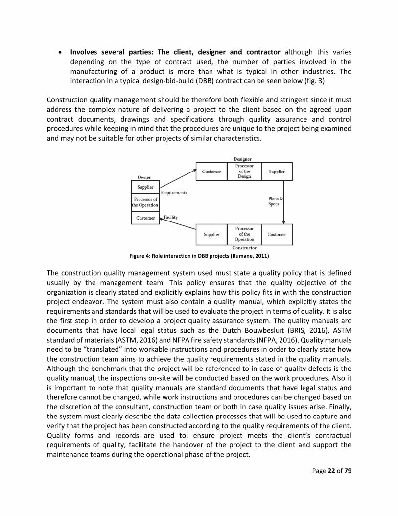
Involves several parties: The client, designer and contractor although this varies depending on the type of contract used, the number of parties involved in the manufacturing of a product is more than what is typical in other industries. The interaction in a typical design-bid-build (DBB) contract can be seen below (fig. 3)
Construction quality management should be therefore both flexible and stringent since it must address the complex nature of delivering a project to the client based on the agreed upon contract documents, drawings and specifications through quality assurance and control procedures while keeping in mind that the procedures are unique to the project being examined and may not be suitable for other projects of similar characteristics.
Figure 4: Role interaction in DBB projects (Rumane, 2011)
The construction quality management system used must state a quality policy that is defined usually by the management team. This policy ensures that the quality objective of the organization is clearly stated and explicitly explains how this policy fits in with the construction project endeavor. The system must also contain a quality manual, which explicitly states the requirements and standards that will be used to evaluate the project in terms of quality. It is also the first step in order to develop a project quality assurance system. The quality manuals are documents that have local legal status such as the Dutch Bouwbesluit (BRIS, 2016), ASTM standard of materials (ASTM, 2016) and NFPA fire safety standards (NFPA, 2016). Quality manuals need to be “translated” into workable instructions and procedures in order to clearly state how the construction team aims to achieve the quality requirements stated in the quality manuals. Although the benchmark that the project will be referenced to in case of quality defects is the quality manual, the inspections on-site will be conducted based on the work procedures. Also it is important to note that quality manuals are standard documents that have legal status and therefore cannot be changed, while work instructions and procedures can be changed based on the discretion of the consultant, construction team or both in case quality issues arise. Finally, the system must clearly describe the data collection processes that will be used to capture and verify that the project has been constructed according to the quality requirements of the client. Quality forms and records are used to: ensure project meets the client’s contractual requirements of quality, facilitate the handover of the project to the client and support the maintenance teams during the operational phase of the project.

Page 23 of 79
Figure 5: Quality management pyramid (Rumane, 2011)
On a more detailed level, the quality management system (sometimes referred to as quality management plan) consists of two main categories: quality assurance (QA) and quality control (QC) systems:
The QA system is a process-based system that consists of the planned and systematic actions necessary to provide adequate confidence that a product or service will satisfy given requirements for quality (ISO). QA in construction projects covers all activities performed by the design team, contractor and quality controller/auditor (supervision staff) to meet the owner’s objectives as specified and to ensure that the project/facility is fully functional to the satisfaction of the owners/end users
The QC system on the other hand, is a product-based system that is used to ensure that that the work is accomplished in accordance with the requirements or standards specified in the contract. Inspection of construction works is carried out throughout the construction period either by the construction supervision team or the appointed inspector agency. On the construction site, inspection and testing is carried out in three stages during the construction period to ensure quality compliance (Rumane, 2011).
During the construction process: This is carried out with the check-list request submitted by the contractor for testing ongoing work before proceeding to the next step.
Receipt of subcontractor or purchased material or services: The contractor submits a material inspection request to the consultant upon receipt of material
Before final delivery or commissioning and handover: The contractor must prove that the project being delivered to the owner fulfills all the agreed upon functional requirements
Therefore, a typical construction quality management plan will have, but not limited to, the following items:

Page 24 of 79
Quality Assurance Items: o Introduction o Project description o Organizational chart of staff responsible for project quality with their respective
qualifications o Responsibilities of staff responsible for project quality and the communication
protocols (ie. in case of escalation of conflicts) o Procedure of submittals: describes the forms that will be used as well as the time
schedule for the submittals of subcontractors, materials, shop drawings and modification requests
o Quality control records and their maintenance o Company’s quality manuals o Quality updating programs o Quality auditing programs o Testing, commissioning and handover o Health, Safety and Environmental aspects (HSE) o Method statement for various works
Quality Control Items: o Quality control procedures: This includes procurement, inspection of site
activities, inspection and testing of systems , off-site manufacturing testing of materials, laboratory testing of materials, inspection of material received on site, protection of works and storage and handling of materials
o Periodical testing programs for machinery and hardware o Project-specific procedures
The construction quality management dynamics are similar to projects in other industries. The feedback from quality control activities serves as a means to determine if the quality assurance practices and procedures are effective in achieving the client’s quality requirements. For example, high rates of rejected work during quality control inspections may indicate that the quality assurance processes involved in a certain activity are ineffective. The construction quality management dynamics therefore are also involve the PDCA cycle of continuous process improvement. The PDCA cycle allows construction teams to rectify their procedures to reduce defects on the project. It also allows for better quality planning procedures in future projects through the retention of knowledge from current corrective and preventive actions that have taken place due to quality defects in previous projects. Applying the PDCA cycle of continuous improvement is difficult due to the uniqueness of construction projects and their surrounding circumstances, no matter how projects of similar characteristics may appear. Another difficulty that this approach faces is the ability to infer and test the improved processes, especially considering the differences in construction practices across companies in the construction industry.

Page 25 of 79
Figure 6: PDCA cycle for construction projects (Rose, 2005)
3.3 The Dutch Quality Directive (Kwaliteitborging) The Dutch regulation regarding the quality on construction projects has been transforming in recent years with legislation changes taking place to the civil code (Burgelijk wetboek). The most prominent (as well as most recent) change that impacts on-site quality is the Dutch quality assurance directive: “Wet kwalitietborging van het bouwen” (Ministerie van Binnenlandse Zaken en Koninkrijksrelaties, 2014). The new regulations amend existing laws and can be categorized into six main articles:
Atricle 1: General amendments
Article 2: The general provisions of the Environmental Law Act (de wet algemene bepalingen omgevingsrecht)
Article 3: The law of economic offences (wet op de economische delicten)
Article 4: The quality assurance for construction (Kwalitietborging voor het bouwen)
Article 5: Provisions for construction practices before the application of the law
Article 6: The law’s information sharing proceedings once the law is applicable
“The general amendments” of Article 1 affect the following sections of the Dutch civil code:
Section 7:758 paragraph 3 : The contractor is liable for defects that are not detected at the completion of the work, unless these defects are not attributable to the contractor
Section 7:676 part A: The contractor provides financial guarantee when entering an agreement with the client to cover the risks resulting from the contractor insolvency as well as to repair defects attribute to the contractor after the completion of the project is then discovered.

Page 26 of 79
Section 7:768 paragraph 2 & 4: The duration of “3 months” in this section is changed to “15 months”
“The general provisions of the Environmental law act” of article 2 impact the following sections of the civil code:
Article 2:10: Environmental permits can be refused by the competent authority if, based on their judgement, information provided is insufficient. Tools of quality assurance shall be appropriate to the risk class of the type of construction referred in section 7
“The impact of the law of the economics” of article 3 is vaguely explained in the law, and it’s implications on the construction process are unclear “The quality assurance for construction” in article 4 amends the following sections in the civil building code:
Section 7AA: Defines terminology used, especially the term quality assurance which defines an evaluation methodology that focuses on constructing a building which has legitimate expectations to meet the requirements laid down as referred to in section 2 of the civil code. The section also defines the roles of two entities: the quality insurer (kwalitietborger) and the admission organization (toelatingsorganisatie)
Section 7AB: Indicates that administrative categories are designated to buildings, which adhere to specific quality assurance tools
Section 7AC: forbids the construction of a building without a tool for quality assurance that: has been admitted by an admission organization, tailored to the risk class of the structure, and finally is applied by the quality insurer
Section 7AD: The quality assurance tool is submitted by the party offering the instrument (ie. contractor) to the admission organization for approval. The following conditions, at least, are required for the tool to meet the law requirements: The manner in which the quality assurance tool is arranged, quality control tool during the construction process, assessing the conformity of the construction with the specifications as mentioned in section 2, the skills and expertise of the quality insurer must be satisfactory and finally, how supervision is managed and the actions/mechanisms during cases of abuse. The section also discusses the grounds on which the admission organization may refuse, suspend or revoke the permits based on unacceptable quality assurance tools or breaches to it once construction commences
Section 7AE: The admission organization’s characteristics are explained in detail as well as their main tasks which are: Decide on the appropriate quality assurance tools for the construction application, change revoke or suspend authorization, conduct random checks of the operation to ensure quality assurance tools are in line with the application, provide information on the application of the tools of the quality assurance system

Page 27 of 79
Section 7AF: Describes the constitution of the admission organization, which includes a chairperson and no more than 2 other members. The members are appointed for a period of 4 years and can be reappointed only once
Section 7AG: Discusses the administrative support that the admission organization receives
Section 7AH: Admission organization establishes management regulations as well as the main features of the mechanism and methodology of the organization
Section 7AI: The annual report provided to the admission organization must include a description of the quality status of the construction project
Section 7AJ: The admission organization keeps a register of all approved quality assurance tools and the respective building categories they can be used for as well as the applications for approving submitted quality assurance tools
Based on the amendments to the civil code discussed above, it can be seen that the focus and burden of the quality control has been steadily increasing towards the contractors through three main aspects:
Legal : Through an extended liability period (3 months to 15 months) which increases the pressure on the contractor to mitigate the risks of latent defects
Bureaucratic: Quality assurance tools become an integrated part of the process to obtain construction permits, as well as including quality reports in the assessment. This increases the risk of revoking, suspending or refusing to grant construction permits, which inevitably increase the risks of project delays and indirectly, project costs.
Communication: Several new entities are introduced in the legislation such as the quality insurer (KwalitieBorger) which as involved in the quality assurance of the construction projects. This increases the need for effective communication tools since the number of parties involved in the project is expected to increase, which adds to the risks of project delivery.
These three main aspects of the amendments to the Dutch civil code further prove the need for new and innovative quality management plans that address the new challenges that face contractors in the execution phase of construction projects. The implementation of BIM in quality management plans on construction sites has been explored in several research studies. The following section discusses the recent approaches and trends of BIM integrated quality management as well as the shortcoming of each approach in addressing the new risks that have risen through legislations.
3.4 BIM and quality management Various researchers have conducted research on methods to implement BIM concepts in enhancing the two pillars of construction quality management: quality control and quality assurance. A secondary, but equally important, aspect in quality management is the communication protocols necessary between the two systems. The communication protocols encompass, but are not limited to:

Page 28 of 79
Organizational structure and responsibilities of project stakeholders: who is responsible for what with regards to quality?
Communication channels: who “owns” the information and with whom should the information be shared?
Frequency of information exchange: how frequently must the quality-related information be shared?
The usefulness of having object-oriented parametric models for quality management lies in their flexibility in dealing with the component’s properties: derived properties can be extracted from a component’s static properties (such as calculating the volume and area of a column by using geometric properties), properties can be extended with attributes that are not part of the component’s standard attributes using linked databases (referred to as semantic enrichment of elements (Solihin & Eastman, 2015) (Dietze, Beetz, & Et. al, 2013). It can therefore be inferred that BIM provides powerful features that address the weaknesses of current management practices, especially if information pertaining to actual site conditions of model elements can be captured and translated into BIM property sets. This reduces the quality management shortcoming mentioned previously and thus greatly reduce on-site quality defects due to efficient information management of real-time construction data. One way to collect the site condition properties is through laser scanners (Bosche, Ahmed, & Et. al, 2015). This allowed geometric point data to be collected, translated and put into a model as part of the as-built models of a project, which were used during the hand over phase of the project. There has also been attempts to implement laser scanning during the construction phase of the project in order to improve planning and scheduling practices (Van Schijk, 2016). Other research investigated the use of 4D models (BIM + schedule) instead of automatic input from laser scanners (Chen & Luo, 2014).The quality control framework proposed a 4D model to be combined with a company’s POP (process, organization & product) model in order to achieve feedback and feedforward loops in the communication channels between different stakeholders on a project with regards to component specifications (product), all stakeholders involved in the component construction (organization) and the steps needed to be taken in order to deliver the component (process). The model was tested on pile foundation construction work in a shopping complex project in China. Research was also conducted on the overall framework of the quality management plan in the hope of combining tools developed for quality control with ones developed for quality assurance (Park, Lee, & Et. al, 2013). The thesis proposes an integrated defect management system that combined knowledge management with onsite quality control using augmented reality. The framework of the knowledge management database relied on three steps or processes in its framework: data (defect) capture, retrieval and reuse. This approach was developed for portfolio management, since it allows information regarding defects from multiple projects, of similar characteristics, to be used for determining possible improvements in the quality control and quality assurance of future projects. The research studies mentioned above used various software tools in order achieve their goals. The most common approach among many of the researches was to link the BIM model (which

Page 29 of 79
was commonly an IFC (Industry Foundation Classes) (BuildingSMART, 2016) model constructed using a popular authoring tool such as Autodesk Revit) with external databases that contained specifications and extra information about model objects. Communication between the databases and the BIM model was usually done through a custom designed graphical user interface (GUI) which was set up using one of the common programming languages (C++, JAVA etc.). Data that required importing/exporting functions between the model and standard reporting programs (MS Excel or Project) was most commonly done through custom created add-ins that perform XML processing between model data (ifcXML) and the reporting software (Kim, Anderson , & Et. al, 2013). XML (or ifcXML in this case) is a standard data serialization format that can be used to capture IFC model instances. This is enabled by, mapping from EXPRESS to XML schema definitions (XSD) using the ISO 10303-28 standards (buildingSMART, 2016). Since XML is an open standard, it is used as a medium of data exchange between software programs (such as MS excel or project). This flexibility is one of the main advantages of allowing XML to be a median in data transfer between various software and IFC models. However, due to the data structure of the XML format, one of its disadvantages is poor scalability. This becomes apparent with large and complex models and can lead to higher processing time and larger files. Attempts to use information and communication technology (ICT) in commercial software packages aimed at improving communication to the construction industry have also been explored. “Snagstream” (www.snagstream.nl) is an example of a program that is used by Dutch construction and development companies, such as Hendricks Bouw en Ontwikkeling, in order to facilitate communication on the construction site through real time data sharing. The software allows site personnel to exchange site information such as highlighting and sharing defect location and description, creating snaglists and sharing multimedia such as site photos or videos. The software is easy to use and is available on portable mobile devices which reduce the workload and paper work previously required by the site supervision staff during site inspections. One of the main disadvantages of the software however is that the data cannot be exported for analysis, which indicates that “lessons learned” on project quality defects through collaborative communication is lost with the handover/completion of each project. Even though extensive research has been conducted and program packages have been developed on the implementation and integration of ICT practices in general, and BIM in specific, into the domain of project quality management, the research has fallen short in providing a comprehensive approach to all aspects of a project quality management: laser scanners are quite expensive and require a high level of expertise to operate. These scanners, while highly efficient in determining defects due to dimensional deviations, are not capable of detecting more subtle defects that require judgement: an example of such a defect would be checking if doors or windows are operating properly after installation. Furthermore, automatic inspections using scanners are used when project components have been complete (ie. the scanner is not involved in the processes leading to the construction of the component). This implies that latent defects are difficult to detect, as well as more costly to repair. A quality control application that is based on 4D BIM and construction codes, which are converted into Process, Organization and Product data structures (Chen & Luo, 2014), provides a solid approach for improving project quality

Page 30 of 79
control practices, the framework however does not address the need to monitor, log and retrieve defect occurrences on a project. The framework therefore does not provide a way to measure project KPIs in terms of quality (approved vs. rejected inspections) in order to improve quality practices in the current project, as well as future project using knowledge management databases. Finally, the quality management framework that uses knowledge management databases and augmented reality quality control is perhaps the most comprehensive approach to provide a complete BIM-integrated quality management plan. Augmented reality (AR), like laser scanners, is a complex tool that is difficult to operate in an industry that still relies on paper-based communication channels. Furthermore, AR has the several unique disadvantages:
AR is currently in its infancy, leading to usage discrepancies and data inaccuracies
It is a complex tool that requires extensive knowledge to utilize
Scalability issues when dealing with complex projects
It also shares the same pitfalls as the laser scanner: it is does not address the process that leads to the construction of the component, since the AR displays the model components “virtually” on site which is not a useful approach when the component’s construction is still in progress.
3.5 Summary of Literature review The literature review provides insight into the research questions that this research paper aims to answer. The literature review indicates that quality defects, both direct and latent, increase project construction costs through schedule overruns, loss of productivity and physical material costs. It also indicates that although various researches on the root causes of construction quality defects and various approaches to mitigate their impact have been conducted, quality defects are still a common occurrence in construction projects. Furthermore, the shifting legislations in the Netherlands has also added pressure on the construction industry to improve current quality management practices. The weaknesses of current quality management practices are mainly attributable to poor information management on construction projects: poor communication between stakeholders, poor managerial and supervision skills, improper documentation of drawings, misunderstanding of specifications between stakeholders and data/knowledge loss. The benefits of implementing Building Information Modeling (BIM) in construction quality management plans can therefore be clearly seen: BIM increases collaborative communication among involved stakeholders, allows sharing of information openly and effectively and acts as a medium for retaining project data for future analysis. There have been several attempts, both academic and commercial, to integrate BIM capabilities into the quality management practices on construction projects, the attempts lacked a comprehensive approach to both QC and QA systems of the quality management system: current BIM integrated approaches where narrow in scope: focusing only on one of the two systems and seldom providing a practical solution that can be implemented on site with the current level of technical know-how, fit unrealistically with current construction quality practices and improperly address the information management issues that are the root cause of quality defects on construction projects.

Page 31 of 79
Both QA and QC systems, as well as the communication protocols between these two systems, therefore need to integrate BIM capabilities in order to deliver a complete solution that can address the shortcoming of the quality management system as a whole. This research paper will therefore propose a BIM integrated quality management framework that will aid QC procedures such as site inspection on construction sites as well as retain project quality KPI metrics for internal audits and analysis in order to improve the QA practices of current projects through corrective action and future projects through revised quality planning approaches.

Page 32 of 79
4. Model
4.1 Introduction A construction quality management plan that integrates BIM into both quality assurance and quality control systems, in order to provide a comprehensive approach to reduce defects on construction sites is proposed in this paper. Minimizing construction defects reduces project costs, reduces schedule delays, boosts resource productivity and improves the overall quality of the project. The developed approach builds on previous research, literature and attempts to incorporate BIM into construction quality management, while noting their shortcomings and disadvantages. The framework proposed in this thesis differs from previous research in that it attempts to integrate BIM concepts within the current construction practices, rather than suggesting new methods that cannot be easily implemented, thus greatly reducing the barriers of industry adoption. The proposed framework does not revolve around automation in decision making processes, which has been a trend in current developments in BIM quality assurance applications (model rule checking software, laser scanners etc.). The decision to discard this possibility is due to two main reasons:
Current construction practices involve a high level of human judgement, especially considering quality management. This requires complex analytical and computational skills that cannot be easily replicated through automation
Automation in construction projects is still in its infancy, indicating that implementing such an approach involves high costs and degree of specialization
The theoretical formulation builds on the findings of the literature review to propose a framework for construction quality management that takes the shortcoming and disadvantages of previous research into consideration. It also decomposes the integrated plan and describes how the plans’ individual systems (quality assurance and quality control systems) will integrate BIM features in order to achieve the overall construction project’s quality objectives: The proposed integrated quality control system ensures that quality requirements are controlled and monitored throughout the construction project progress, while the proposed quality assurance system ensures that the results/output of the quality control system is properly documented, easily retrieved and efficiently shared in order to:
Monitor individual project quality performance
Determine poor processes that lead to quality defects
Create record keeping practices that will become increasingly influential in Dutch construction practices due to changing legislation
The proposed framework also highlights the communication requirements and interaction between the two systems in order to create a comprehensive quality management approach. This has been lacking in previous research developments, focusing on implementing BIM concepts to specific aspect of the quality management, rather than proposing a complete solution that can substantially improve all aspects of current quality management plans.
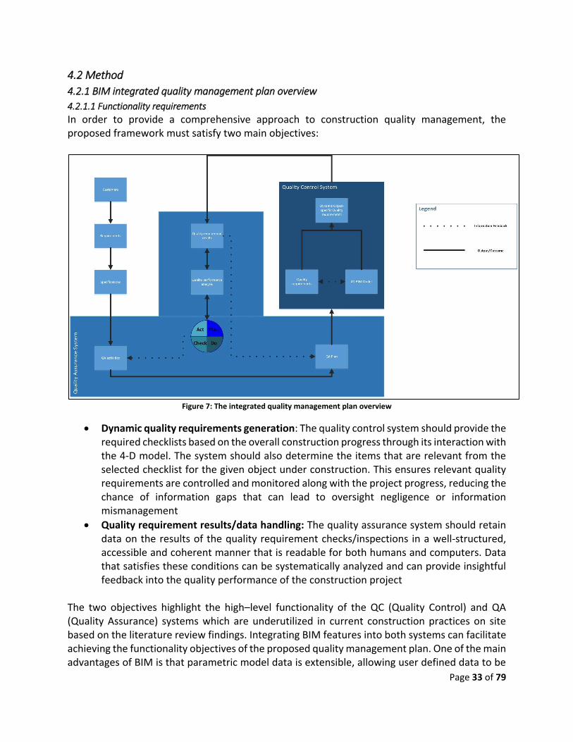
Page 33 of 79
4.2 Method
4.2.1 BIM integrated quality management plan overview
4.2.1.1 Functionality requirements
In order to provide a comprehensive approach to construction quality management, the proposed framework must satisfy two main objectives:
Figure 7: The integrated quality management plan overview
Dynamic quality requirements generation: The quality control system should provide the required checklists based on the overall construction progress through its interaction with the 4-D model. The system should also determine the items that are relevant from the selected checklist for the given object under construction. This ensures relevant quality requirements are controlled and monitored along with the project progress, reducing the chance of information gaps that can lead to oversight negligence or information mismanagement
Quality requirement results/data handling: The quality assurance system should retain data on the results of the quality requirement checks/inspections in a well-structured, accessible and coherent manner that is readable for both humans and computers. Data that satisfies these conditions can be systematically analyzed and can provide insightful feedback into the quality performance of the construction project
The two objectives highlight the high–level functionality of the QC (Quality Control) and QA (Quality Assurance) systems which are underutilized in current construction practices on site based on the literature review findings. Integrating BIM features into both systems can facilitate achieving the functionality objectives of the proposed quality management plan. One of the main advantages of BIM is that parametric model data is extensible, allowing user defined data to be

Page 34 of 79
linked to the model objects. Having extensible 4D models that can include links to data such as quality requirements facilitates the dynamic generation of site inspections, allowing stricter feedforward loops into the control and monitoring process of the construction activities: The stakeholders can determine the relevant quality requirements for objects that are currently under construction, and can manage requirement checks in case of activity rescheduling without the risk of information gaps between stakeholders. Another powerful feature of BIM is that model data is also extendable, allowing data that describes certain features, properties or states of an object to be created and added. The BIM extendibility feature allows data that is well-structured according to classification standards to be created and added to model objects, such as the established or custom property sets. Data can not only be added to an object’s properties, it can also be extracted from them. The ability to extract data from model objects ensures that only relevant inspections of certain properties are generated and filtered to the end user through the quality control system. The extendibility feature also allows performance analysis to be conducted on several projects of similar characteristics that are using similar objet properties. The results can provide useful insight into future quality assurance planning which allow continuous process improvement in order to reduce the occurrence of defects on future projects.
4.2.1.2 Communication and data exchange overview
The proposed construction quality management framework requires that communication and data exchange between the QC and QA systems be as automated as possible in order to reduce the pitfalls of poor information management that current construction projects face. Nevertheless, Input from external sources such as on-site inspections, corrective action and updated construction process development would be required to supplement the data and add valuable information that cannot be easily captured throughout each process that is carried during the information exchange (Fig. 8). The extended 4D model, which also links quality requirement data to model objects, will provide an object-referenced quality requirement list for objects that are currently under construction based on the updated project schedule. The list of generated requirements would then be checked on-site through scheduled inspections based on the agreement between the project’s stakeholders. The input from the site inspections would allow the results to be transferred into a storable and retrievable data format. The stored data provides an efficient method to determine and display quality requirements that have failed during the inspection (defects) quickly and efficiently in order to allow prompt corrective action to take place. Further inspections would be required in order to determine if the corrective actions have been successfully performed. The requirements that would demand re-inspection would therefore be communicated back to the quality control system. Quality requirement results can also be analyzed further at a project level to provide insight regarding current quality control processes and their effectiveness in limiting defects.

Page 35 of 79
Figure 8: process overview of proposed quality management plan
Based on the insight, construction process adjustments can be proposed through the “Plan-Act-Do-Check” cycle which can translate into updated quality control processes such as: updated construction processes (updated activity sequencing, logic and implementation methods) or variations in current supply chain practices. The updated construction processes and supply chain approaches are fed back into the quality control system through updated project scheduling techniques, adding/removing quality requirements or modifying current checks/inspections.
4.2.2 Quality Control System overview The quality control system is at the heart of the proposed construction quality management framework. Quality control provides the mechanism for monitoring quality on construction projects as well as reviewing and assessing quality results of inspections. Quality control also determines the communication and exchange of data and results between stakeholders. Quality control however is as effective as the management plans developed through quality assurance practices. This implies that the weakest link in quality management plans are quality control systems: extensive and meticulous quality assurance plans can still lead to quality defects if quality control practices are poorly conducted. It is also important to note that the main weaknesses of current construction management plans mentioned previously in the literature review occur in the quality control system (failure to detect defects, poor communication and data exchange etc.) while quality assurance system weaknesses are limited to the inability, or inadequacy, of current knowledge management approaches which do not retain knowledge or “lessons learned” effectively. It is therefore important to emphasize the importance of the proposed BIM-integrated quality control system and it’s dynamics in the overall framework. This includes a description of the interaction between the extended 4-D model components in order to overcome current practice weaknesses, as well as determine the logical flow of operations
Inte
gra
ted
Qu
alit
y M
an
ag
em
en
t Fr
am
ew
ork
Co
nst
ruct
ion
te
am
Da
ta E
xch
an
ge
Ma
na
ge
me
nt
Start
Create 4D BIM
Develop quality
requirements
List of requiredSite inspections
Update Project schedule based on
progress
Conduct on Site
Inspections
Quality Inspectionresults
Quality inspection approved?
Conduct data analysis on
results
Yes
No
Perform correctiveactions
End
Requirement data
adjustments
QualityKPIs
Color coded model
Collaborative data

Page 36 of 79
that requires data to be accessed, retrieved and analyzed from the extended 4-D model components. The proposed QC systems’ structure focuses on associating the scheduled activities with respective objects in the BIM model. The association between the model and the activities are maintained in the 4-D BIM model using the IFC (Industry Foundation Class) attributes and their defined relationships (inheritance graphs) that are part of standardized schemas (IFC 2x3). The IFC format is a neutral data format that has been developed by BuildingSMART, an international model and implementation support group that aims to standardize BIM data models (BuildingSMART, 2016). In order to free the system from the burden of incorporating repetitively the results of the updated progress of scheduled activities in the 4-D model (i.e. updating IfcTask “percentage complete” in the 4-D model once a schedule update has taken place), which may increase the size and complexity of the 4-D models as well as result in unnecessarily increase the size of 4D models whenever the project schedule is updated (This becomes an issue for large and complex projects), a more flexible system has been proposed. The 4D model would therefore be created once: for the baseline schedule, while the project schedule would be updated regularly and independently of the BIM model to track on-site progress. The QC system would facilitate the exchange of information from the 4D model by identifying and matching the activities that are currently in-progress in the updated schedule with the activities available in the 4D BIM/IFC model, and their related model objects. The extracted data (both the activity and its associated object’s properties) will then be used to determine if a check/inspection is required to be performed from a mapped schema for the conditional requirements. If all preconditions are satisfied for a given quality requirements to be conducted, the requirement will be displayed for the end user. However, the requirement will only be displayed to the end user after scanning the QA system database, which consists of results of previously conducted on-site quality inspection, in order to eliminate the possibility of displaying a requirement that has already been checked and approved (Fig. 9).

Page 37 of 79
Figure 9: Structure of QC system
The QC system requires several logical analyses to be performed on the retrieved data from the extended 4-D model components in order to evaluate and display the required quality requirements based on the updated on-site construction progress. The updated progress schedule needs to be analyzed first in order to determine which activities are in-progress and completed. The list of in-progress and completed activities are needed in order to determine if the conditional process requirements of the quality checks/requirements are met. The in-progress activities from the updated schedule are then compared to the activities that are in the 4D model in order to retrieve the model objects through the association relationship between model objects and the project activities that is captured in the IFC model instance. Determining the model objects, and their respective attributes, associated with activities that are in-progress enables the QC system to determine if the conditional product requirements of the quality checks/requirements are met. In order for a quality check to be generated, the conditional requirements (both process and product) need to be met, otherwise the quality requirement is not intended at this phase of the project (conditional process requirement mismatch) or it is not required for this type of object and its associated properties (conditional product requirement mismatch). In certain cases, quality check items require only a conditional process requirement to be met (ex: procurement of certain materials at the beginning of the project, visiting supplier factories etc.). For these cases, the conditional process requirements are checked for activities that are in-progress but are not associated to a specific object in the 4D model. The requirement results are then generated for the end user, ensuring that only relevant check items are displayed at the correct phase of the project progress.
Database
Quality Control System
4D BIMConditional
RequirementsUpdatedSchedule
Model ElementsQuality
requirementsInspections

Page 38 of 79
Figure 10: QC analysis flow chart
The systems aims to minimize the amount of quality-related information/data that the stakeholders have to deal with during the construction of the project, focusing on providing the relevant quality requirements at the necessary phase of construction progress. The assumption is that minimizing the amount of data that the stakeholders need to be cope with diminishes the weaknesses of current quality management practices on site: it reduces the chances of communication mismanagement, the possibility of overlooking certain relevant checks and poor site supervision, managerial errors and the chance of data loss. In order for the QC system to correctly determine the quality requirements, preconditions needs to be met for each item in the quality requirement database. These preconditions can be thought of as triggers for the specified quality check/item and are divided into two main categories: process and product conditional requirements. Process conditional requirements relate to the sequencing of scheduled activities and their status during the course of the construction project.
Ifc Model
PRODUCT REQUIREMENTS
Model element
Ifc inheritance graph Object instance attributes
IfcRelAssignsToProcss
PROCESS REQUIREMENTS
Project Schedule
Individual activity attributes
Work Breakdown Structure
Figure 11: Conditional requirements
DetermineActivity status
Determine elements
concerned
Determine if prerequisites
are met
Ifc Model
PRODUCT REQUIREMENTS
Model element
Ifc inheritance graph Object instance attributes
IfcRelAssignsToProcss
PROCESS REQUIREMENTS
Project Schedule
Individual activity attributes
Work Breakdown Structure
Conditional prerequisites
Entity relationships
Updated schedule
Determine the quality
requirement
Quality requirements
Generate results
Page 39 of 79
Process preconditions indicate at which point in time a quality requirement check needs to be conducted: it therefore involves one or several activities at various stages of completion. The combination of activities and their completion statuses are “mapped” to the respective quality check items. Mapping the correct combination of activities to the quality requirements eliminates the risk of generating the incorrect quality checks, especially when several activities are linked to a model element (e.g.: “Formwork preparation”, “concrete casting”, “Formwork removal” and “concrete curing” are all activities related to a single model element: IfcColumn. However the quality checks vary significantly for each task) (Fig. 12). As for the product conditional requirements, they relate to the objects in the IFC model and their respective properties and attributes. The product preconditions determine to which element the quality check is relevant. Element properties are unique to each element instance in the model, allowing the product preconditions to be specific to a subtype of model elements (e.g.: checks to be conducted on internal partitioning walls should not be triggered once work has begun on the exterior walls) or to a certain element property (e.g. certain checks need to be done only on fire-resistant internal doors only, which is possible to determine through the “IsExternal” and “Fire Rating” property in the door property set “Pset_DoorCommon”). The product preconditions are also mapped to the respective quality check items. The end result of the preparation is a mapped schema relating the preconditioned requirements (both process and product) to the quality requirement checks/items (Fig 12.). The QC system’s generated results are also an important link to the QA system in the proposed quality management framework: they must be organized in a uniquely identifiable manner so that results of the site inspections can be associated to the respective requirements once the input from the site has been registered. The system results’ data format must therefore be compatible with the QA system’s proposed knowledge management capabilities: data must be storable, accessible and retrievable. Databases provide the required functionality to perform the QA system’s intended functionality and provide several advantages:
Allows data to be viewed by several users simultaneously
Widely used and easily maintained
Controls data redundancy
Enforces integrity constraints (Entity, Referential etc.)

Page 40 of 79
Figure 12: The process and product prerequisite mapping schema
It is important to mention that the generated results have a many-to-many relationship between the requirements and the associated model objects: an object may require more than one quality requirement at various points in the construction process, while a requirement check may be necessary to be carried out on several model objects. In order to maintain the integrity constraints and ensure proper database management, the inspection results are generated as an association table, with each entry indicative of an inspection “instance”, linking a quality requirement to an IFC object (Fig. 13). The inspection “instances” are used by the QA system to display the required inspections that need to be conducted on-site to the concerned stakeholders.

Page 41 of 79
Figure 13: QC System results/output
It is important to also mention that the developed mapping scheme is a result of the experience and understanding of the construction engineers and the quality reviewers: it is up to the construction engineering team involved to determine which combination of scheduled activities and model object properties “trigger” a quality requirement check/inspection. The mapped conditional requirement is therefore an agreed upon guideline that determines “when” and “where” are the quality requirement checks that are currently conducted on construction projects necessary. The schema’s flexibility to accommodate changes and adjustments to both product and process-oriented preconditions is key to the integration of the QC and QA systems as part of the proposed quality management framework. The engineering team can gauge the results of quality inspections as the defect causes are captured and stored as part of the QA system. The results are analyzed to determine the effectiveness of current quality management plans and the quality performance index of the project. The results of several projects with similar characteristics can also be aggregated to generate trends and statistical results that highlight possible quality issues that require strategic planning at a portfolio level (e.g. the continuous poor performance of a supplier/subcontractor). Analysis of these results yields recommendations and suggested improvements by the engineering team to current quality control systems. These adjustments are as part of the continuous improvement strategy that is represented in the Plan-Do-Act-Check cycle of the quality management framework (Fig. 1). The adjustments are reflected in two parts of the QC systems: The quality requirement database and the mapped conditional schema. The adjustment and improvement may be in the form of additional quality checks to be included in order to reduce the frequency of rejected work, or

Page 42 of 79
removal of a certain quality requirement that is not necessary or redundant based on the analysis of results. In both cases, the database accommodates the improvements which will be used on future construction projects as part of the quality control system. The added quality requirement items require demand pre-conditional process and product requirements to be added to the mapped schema as well. The other option for improvement implementation is to adjust the process and product conductional requirements in the mapped schema based on drawn conclusion and findings from the QA system analysis without adding or removing quality requirements to the database. These adjustments may indicate, for example, that:
Quality inspections are being conducted at the incorrect time frame in the construction process of certain project elements (process adjustments), reducing the effectiveness of the inspection or
Quality defects are occurring on elements that were not thought to require certain quality inspections/checks. Thus the need to generalize, specify or modify product preconditions to project element types and their properties.
4.2.3 Quality Assurance System overview The QA system’s main functionality is to create a knowledge management system that can manipulate quality inspection data in order to provide insight into the effectiveness of the project’s quality management plan. The system provide immediate feedback into the QC system when inspections are rejected, allowing works to be immediately rectified while incurring the minimum correction costs. The system also facilitates analysis of quality performance at a project level, shedding light on ineffective processes, work methods, or material that were previously undiscovered due to ineffective measurement methods. This allows for improvements in quality management plans in future projects. In order to achieve this functionality, the system must exchange data at various instances during the progress of the project: the system must display the inspections required to be conducted to the responsible stakeholder, as well as receive input on the results of the on-site inspections. Therefore, user interaction between the stakeholders and the QA system is a key feature of its functionality. This interaction is captured by a proposed user interface that displays the results of the QC system, which are stored in the database, in a user-friendly manner that is easy to read. The interface also allows input regarding the inspection results to be added by the user such as: “Date of inspection”, “comments”, “reviewer” and “Approved/Rejected”. The results of the input by the stakeholders must also be captured, stored and linked to the inspection “instance” that relates to it. In order to maintain the integrity constraints between the “inspections” and “results” tables, it is important to understand the relationship between them. An inspection “instance” may be conducted once if it is approved, but there is a possibility of conducting the same inspection “instance” several times due to repeated rejections of the work several times in some cases. This indicates that each inspection “instance” may relate to several result “instances”, depending on the outcome of the site inspection. The relationship between the two tables is therefore a one-to-many relationship in a database management system context.

Page 43 of 79
Figure 14: QA system Input/output
In addition to the providing an interactive interface between the stakeholders and retaining inspection results, a beneficial feature of the QA system would be to provide a spatial reference between the inspections and their results with the model’s objects, as well as coordination data to feedback information to the QC system. The spatial reference of the inspection results is proposed to be displayed in a color-coded 3D model that translates the results of the inspections into several distinct colors. Since inspection results have a Boolean nature, regardless of the comments of the inspectors, the color code will therefore be limited to two possibilities: “Accepted” (green) or “Rejected” (red) work. Allowing such spatial referencing provides several advantages:
The color-coded model reduces the chance of negligence or oversight by management: rejected work can be visually highlighted and can serve as a reminder of the need for re-inspection, as compared to traditional paper-based or email-based reminders that can be overlooked causing delays in progress.
Spatial referencing of inspection results allows additional insight into the quality performance of the project once analysis is conducted: in addition to the inspector’s/reviewer’s comments, the location of object where the failed inspection has taken place can provide valuable clues to the cause of the defect. The insight is used to limit or reduce the occurrence of such defects in future projects
The end result of the QA system is a database table that contains the “results” table linked to an “inspections” table, data that can be feedback to the QC system, and a color-coded model that displays the status of the inspections in a spatial contexts as soon as the inspections are submitted.

Page 44 of 79
4.3 Results
4.3.1 Section Introduction In this section, the proposed quality management framework is developed into a functioning prototype system in order to demonstrate how the framework would work in the context of current construction practices and projects in the Netherlands. The system was developed in collaboration with Hendriks Bouw & Ontwikkeling BV, a Dutch construction and project development company based in Oss. The company has contributed valuable information to this thesis in the form of access to company data, arranged site visits and on-site meetings, insight into the Dutch construction process and improvement suggestions to the theoretical quality of the framework. The developed framework in this section is therefore heavily influenced by the information supplied by and discussions conducted with Hendriks Bouw & Ontwikkeling BV, which may result in a quality management system that may not be suitable to many construction firms due to varying construction methods/processes, organizational structures or complexity of projects (contracts). This section must therefore be considered as a “proof of concept” rather than a final solution in which an optimal approach to developing the framework is proposed. A customized quality management framework will be required based on the company’s needs and requirements, following the theoretical guidelines proposed earlier to achieve this goal. The development of the framework begins with the collection of gathered data that has been accumulated by their maintenance and services department regarding latent defects that occur after project handover over a period of several years. The data is analyzed and its results serves as a validation for the thesis’ main hypothesis regarding the frequency of occurrence of defects, their effects on the construction projects and the inadequacy of current construction quality practices. The collected data also defines and narrows the scope of the framework that will be developed by focusing on the quality requirements for construction elements/objects and their respective latent defects that have the highest frequency of occurrence. The findings will be compared to the paper’s hypotheses regarding the nature of construction defects and the frequency of their occurrence. This approach is justified since quality requirements (in the form of checklists) are currently not properly formulated at an industry level in the Netherlands. Formulating a complete set of quality checklists for all activities and elements of a project, although highly beneficial for a complete functional framework, is beyond the scope of this paper. The capabilities of the implemented tools are demonstrated and tested in a pilot project. The pilot project’s deliverables includes a BIM model and a construction schedule. The quality requirements for those defects were formulated through discussions and meetings with construction site supervisors based on their experience in controlling and monitoring site progress. The site supervisor’s input regarding the product and process conditions that are required to trigger a quality inspection is needed in order to create a QC system that can generate the required inspections throughout the project progress. The quality requirement data will be linked to the BIM model and the project schedule (4D model), while providing a clearly defined

Page 45 of 79
mapping schema between the quality requirements, the model’s objects and the causes of defect. A well-defined mapping schema between the requirements and the defect causes ensures that a limited set of causes can be consistently identified and documented so that meaningful analysis can be conducted on the project’s quality management practices. On the other hand, a well-defined mapping ontology between the model’s objects and quality requirements ensures that requirements are generated according to the attributes and properties of the model’s objects (i.e. not all instances of an object would require the complete set of quality requirement checks). The site supervisors’ opinions regarding the user interface of the QA system is also taken into consideration since they are the end users that will be interacting with the system in order to view the required inspections and log the results. The QA system’s ease of use and design (front-end design) is of importance in order to ensure enthusiasm and early adoption among the stakeholders. An important feature of the QA system is its ability to spatially reference the location of the inspection for the concerned element. The results of the generated list of quality requirement checks/inspections are captured and stored through input from the site supervisor conducting on-site inspections. The results will be linked to the model and its objects in order to provide feedback to the project’s quality control system. The data also allows analysis of project quality performance (or portfolio quality performance in the case of aggregated results of several projects) in order to reduce defects on construction projects through improved construction processes and updated quality assurance planning. The results of each step in the development process are documented and were discussed in this section of the paper, providing a guide to develop the theoretical quality management framework into a functional system that can be used in construction projects.
4.3.2 Latent defects Statistics The maintenance and management department at Hendriks Bouw & Ontwikkeling BV has been involved in rectifying defects due to complaints from customers after project handover, as well as logging their characteristics and the frequency of their occurrence. These defects occur during the liability/ guarantee period in which the contractor is responsible for rectification of the defects (garantie en nazorg). The complaints have been recorded for three consecutive years, from 2012 till 2014, along with information such as description of defect (omschrijving), date of registration of complaint (Datum melding), origin of the complaint (Klachtoorsprong) and the responsible party for performing the corrective action (Op te lossen door). Each complaint has been categorized into a specified code based on the defect type (nazorgcode), in order to group several complaints and relate them to a specific work package. The complete list of records and the statistical summary can be found in the appendix (Appendix A). The data for the number of complaints per year (Table 1), while not enough to draw conclusions or patterns, indicates that quality defects are still a common occurrence in construction projects. The large number of complaints after hand over also highlights the ineffectiveness of current quality management practices in reducing the occurrence of latent defects. The number of
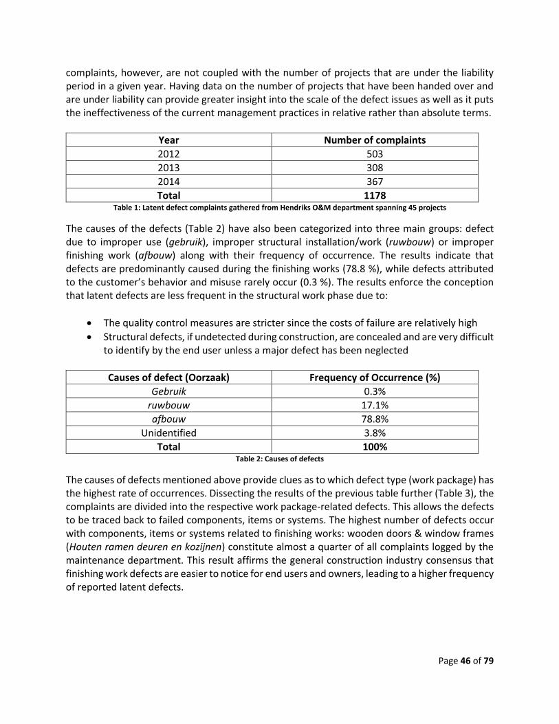
Page 46 of 79
complaints, however, are not coupled with the number of projects that are under the liability period in a given year. Having data on the number of projects that have been handed over and are under liability can provide greater insight into the scale of the defect issues as well as it puts the ineffectiveness of the current management practices in relative rather than absolute terms.
Year Number of complaints
2012 503
2013 308
2014 367
Total 1178 Table 1: Latent defect complaints gathered from Hendriks O&M department spanning 45 projects
The causes of the defects (Table 2) have also been categorized into three main groups: defect due to improper use (gebruik), improper structural installation/work (ruwbouw) or improper finishing work (afbouw) along with their frequency of occurrence. The results indicate that defects are predominantly caused during the finishing works (78.8 %), while defects attributed to the customer’s behavior and misuse rarely occur (0.3 %). The results enforce the conception that latent defects are less frequent in the structural work phase due to:
The quality control measures are stricter since the costs of failure are relatively high
Structural defects, if undetected during construction, are concealed and are very difficult to identify by the end user unless a major defect has been neglected
Causes of defect (Oorzaak) Frequency of Occurrence (%)
Gebruik 0.3%
ruwbouw 17.1%
afbouw 78.8%
Unidentified 3.8%
Total 100% Table 2: Causes of defects
The causes of defects mentioned above provide clues as to which defect type (work package) has the highest rate of occurrences. Dissecting the results of the previous table further (Table 3), the complaints are divided into the respective work package-related defects. This allows the defects to be traced back to failed components, items or systems. The highest number of defects occur with components, items or systems related to finishing works: wooden doors & window frames (Houten ramen deuren en kozijnen) constitute almost a quarter of all complaints logged by the maintenance department. This result affirms the general construction industry consensus that finishing work defects are easier to notice for end users and owners, leading to a higher frequency of reported latent defects.
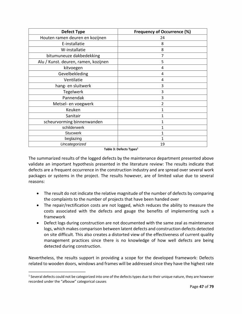
Page 47 of 79
Defect Type Frequency of Occurrence (%)
Houten ramen deuren en kozijnen 24
E-installatie 8
W-installatie 8
bitumuneuze dakbedekking 7
Alu / Kunst. deuren, ramen, kozijnen 5
kitvoegen 4
Gevelbekleding 4
Ventilatie 4
hang- en sluitwerk 3
Tegelwerk 3
Pannendak 3
Metsel- en voegwerk 2
Keuken 1
Sanitair 1
scheurvorming binnenwanden 1
schilderwerk 1 Stucwerk 1 beglazing 1
Uncategorized 19 Table 3: Defects Types1
The summarized results of the logged defects by the maintenance department presented above validate an important hypothesis presented in the literature review: The results indicate that defects are a frequent occurrence in the construction industry and are spread over several work packages or systems in the project. The results however, are of limited value due to several reasons:
The result do not indicate the relative magnitude of the number of defects by comparing the complaints to the number of projects that have been handed over
The repair/rectification costs are not logged, which reduces the ability to measure the costs associated with the defects and gauge the benefits of implementing such a framework
Defect logs during construction are not documented with the same zeal as maintenance logs, which makes comparison between latent defects and construction defects detected on site difficult. This also creates a distorted view of the effectiveness of current quality management practices since there is no knowledge of how well defects are being detected during construction.
Nevertheless, the results support in providing a scope for the developed framework: Defects related to wooden doors, windows and frames will be addressed since they have the highest rate
1 Several defects could not be categorized into one of the defects types due to their unique nature, they are however recorded under the “afbouw” categorical causes

Page 48 of 79
of occurrence. Since repair costs are not available, the assumption is that by reducing these types of defects, the greatest reduction in overall latent defect costs is achieved.
4.3.3 Project deliverables
4.3.3.1 The 4D model
The pilot project that is used to demonstrate the developed quality management system on, is the Hutgraaf project which is a residential construction project that will realize 140 houses in the town of Beuningen (NW of Nijmegen, The Netherlands). The project is being realized in phases and has completed the first phase, consisting of a total of 37 houses. Construction is currently proceeding on the second phase of the project, which has a scope of 29 housing facilities to be realized. The structural works for Phase 2 have been completed, making the project ideal to test the developed system since the quality system will be limited in scope to quality defects relating to door and window frames.
Figure 15: Layout of Phase 1 & 2 of Hutgraaf project
The Hutgraaf project’s housing facilities are typical houses that follow standard Dutch architecture, structure and work methods. A schedule has been developed by Hendriks for such projects, in order to facilitate the monitoring of progress and estimation of work durations. These standard schedules are flexible and can be scaled to the scope of the various projects. The standard schedule (“WBC Standard planning”) is used for all the phases of the Hutgraaf project. The advantage of using a standard schedule plan as part of the proposed quality management system is that the results can be easily replicated to several project that have the same characteristics. In order to integrate the IFC model and the schedule for the Hutgraaf project into a 4D model, SYNCHRO, a commercial 4D BIM visual planning, scheduling and project management software,

Page 49 of 79
will be used. There are several other commercial software that have the functionality as SYNCHRO, however SYNCHRO has several advantages:
The program has an intuitive layout design and is easy to use and learn
The software has an extended (free) license for academic use that can be extended on request
The software is compatible with several standard scheduling formats (Asta power project, MS project and Primavera P6) that can be used to create the 4D model
Figure 16: The Hutgraaf project (Phase 2) – Tekla BIMsight
The IFC model is first imported into SYNCHRO, while the schedule is first converted into XML format before being imported into the software as well. All project schedules created using standard scheduling software (MS project, ASTA power project and Primavera P6) can be exported into a XML file that validates from a unified XML schema (i.e. common XML namespace) (Microsoft, 2016). The model elements from the IFC model are displayed as “resources”, and can be assigned to one or several tasks/activities (Fig. 10). Similarly, several tasks can be assigned to a resource if necessary. Once the resources are assigned to the activities, the project is exported to an IFC file. During the export, SYNCHRO ensures that all the 4D attributes are retained in the IFC file based on the IFC 2x3 standard schema:
Activity entities are created and stored in the IFC file as “IfcTask” (Ifc 2x3: IfcTask)
Activities are linked to the model objects through the “IfcRelAssignsToProcess” entity, where the schema links the RelatedObjects and the RelatingProcess (activities) (Ifc 2x3: IfcRelAssignsToProcess)
The “IfcTask” entities in the IFC model ensure that the updates of the progress that occur in the schedule can be identified in the IFC model through simple comparisons of activity properties such as activity name, durations and relationships. This allows activities that have been completed or are in progress to be identified in the IFC model. The “IfcRelAssignsToProcess”

Page 50 of 79
entities are used to identify the model elements and their properties that are linked to the activities in question. Identification of the activities and the model objects is necessary in order for the proposed QC system to perform an analysis to determine if the conditional requirements (process and product) have been met. The end result of this process is an exported IFC model from SYNCHRO that contains the embedded 4D attributes (“IfcTask”, “IfcRelAssignsToProcess” etc.) necessary for the framework to function. It is important to note that during the export, several user-defined object properties (eg: supplier information/serial number, Thermal transmittance) are not preserved in the new exported model. Additionally, properties are reclassified under one new property set only: “SynchroResourceProperty”. Although this is not problematic for the validation scope within the context of this thesis, since the basic properties exported are sufficient to determine if the product conditional requirements are met, it may be an issue for more complex requirements that demand the extended user-defined properties to verify if the conditional requirements have been met.
Figure 17: creating the Ifc model with 4D attributes
4.3.3.2 Quality inspections
The quality requirements/inspections that need to be carried out during the construction process for window and door frames have been agreed upon and developed with the responsible project stakeholders:
The construction team of the Hutgraaf project: responsible for site inspections and the daily supervision of the work activities
The BIM manager: responsible for maintaining the project BIM model and coordinate any revisions during the construction or during handover of the project
The project leader (projectleider): responsible for managing the project and the construction team in order to complete the project within budget, at the agreed upon schedule and within the agreed upon scope

Page 51 of 79
Currently, the construction quality inspection plans are not well developed to the point that can service the needs of the proposed Dutch quality assurance law. Although many contractors have taken individual steps to create company-specific quality standards, the efforts are highly fragmented at an industry level. An attempt to create an industry wide quality planning standard (Controleplannen) has been conducted by the Centraal Bureau Bouwbegeleiding (CBB, 2016) (Controleplannen), however the proposed standard has not been widely adopted.
Requirements Source
Werkbezoek aan fabriek, eventueel meerdere bezoeken
CBB controleplan 30
Controle aanvoer kozijnen
Hebben de sparingen de juiste afmetingen (inclusief tolerantie)?
Hendriks Keuringsplan 3.C.3 21-1 & 21-2
Zitten de sparingen op de juiste plaats?
Controle bevestiging in het werk, niet aan buitenmetselwerk bevestigd
CBB controleplan 30
Kozijnen en beglazing volledig afplakken
Kwaliteit (let op beschadigingen) bij plaatsen Hendriks Keuringsplan 3.C.3 40 - 1
Kwaliteit (let op beschadigingen) bij oplevering Hendriks Keuringsplan 3.C.3 40 - 1
Zijn revisietekeningen gemaakt/noodzakelijk Hendriks Keuringsplan 3.C.3 40 - 1
Zijn attesten aanwezig Hendriks Keuringsplan 3.C.3 40 - 1
Binnenkozijnen schoongemaakt Hendriks Keuringsplan 3.C.3 40 - 1 Table 4: Window & Door frames quality requirements
The list of quality inspections/checks proposed (Table 4) is based primarily on the company’s current quality plans. However, several inspections from the CBB quality plans were deemed useful to be included in the window and door frames requirements for the validation process. The result is a quality requirement plan that combines both items from both the industry-proposed CBB plans and Hendriks Bouw & Ontwikkeling’s current construction quality plans (Keuringsplan).
4.3.3.3 Quality conditional requirements
Based on the developed quality requirements list mentioned above (Table 4), the conditional triggers must be determined so that the correct inspection for the related element is triggered at the appropriate point in the construction progress. The schedule of the Hutgraaf project is based on the “Standard WBC planning” (Hendriks Bouw en Ontwikkeling, 2014) template that is developed by Hendriks Bouw & Ontwikkeling for residential construction projects of standard (in the Dutch context) scope and work packages. Due to the repetitive nature of these projects, the productivity is estimated to a high degree of accuracy. The schedule is therefore used for duration estimates during the bidding phase, as well as for more detailed planning during the mobilization of the resources once construction begins: weekly schedules (Uitvoeringstijdschema) that are used on site and usually contain more detailed

Page 52 of 79
planning are derived from the template. An advantage of applying the proposed quality management framework on this schedule is that the conditional requirement triggers can be replicated to other projects of similar scope using the template with minimal effort. The list of activities that relate to each quality check in the schedule have been identified, as well as the phase in which they warrant an inspection/check (Table 5). The table below filters out checks that are not relevant to the current project, focusing only on inspections relevant to the project. Based on the stakeholder’s reasoning, only two phases for scheduled activities are of interest based on the validation scope: an activity that is currently under progress (started) and an activity that has been done (completed).
Check item Activity Phase
Started Complete Hebben de sparingen de juiste afmetingen (inclusief tolerantie?)
Lijmwerk kalkzandsteen elementen
Lijmwerk 1e verdieping kalkzandsteen
Lijmwerk 2e verdieping kalkzandsteen
X
Zitten de sparingen op de juiste plaats?
X
Controle aanvoeren kozijnen Stelwerk begane grond
Stelwerk 1e verdieping
X
Kwaliteit (let op beschadigingen) bij plaatsen
X
Kozijnen en beglazing volledig afplakken
X
Kwaliteit (let op beschadigingen) bij oplevering
Vooropname intern X
Binnenkozijnen schoongemaakt X
Zijn attesten aanwezig Opleveren X
Table 5: process conditional requirement (mapping)
It is important to note that the two phases mentioned are not the only possible “forms” of an activity that act as conditional triggers for the quality checks. More complex quality checks may be triggered:
At a specific point in the activity progress (e.g. Inspection “A” needs to be conducted when activity “X” is 60 % complete)
Through the predecessor/successor relationships between the scheduled activities (e.g. Inspection “B” is only conducted if Activity “Y” is followed by Activity “Z” , all other cases for Activity ”Y” are discarded)

Page 53 of 79
The complexity of the conditional prerequisites is proportional to the complexity of the work activity associated with the element being constructed. Since window and door frame installations are a relatively straightforward, the quality inspections developed for the wooden door and window frames do not capture such complex prerequisites scenarios. As for the product conditional requirements, the activities of interest in the project schedule relate to two general element model categories: External walls (with their respective openings) and the elements that are associated to these openings (External windows/Doors). Each category has several requirements that demand all of them to be fulfilled in order for the inspections to be generated. Due to the scope of the validation, only two generic conditional requirements for the external windows/doors elements are captured: the elements related to the activity should be of type “door” or “window” and the element must be externally located. As for the external walls and their openings, several requirements must be fulfilled in order for the quality inspection items to be generated. In addition to the element type (“IfcWall”) and external location requirements, two other requirements must also be met: only external walls of specific material (“Limestone”) and contain openings for doors and windows are considered (Table 6). These two additional requirements for the external walls and their openings are due to the model’s specific characteristics: The wall material requirement ensures that duplicate inspections are removed from the generated results since other several model elements are also modeled as external walls (e.g. brick wall/façade wall, insulation layer (glasswool) between façade and limestone wall). Due to the walls being geometrically represented as “boundary representations” (B-rep) in the IFC model, determining if the walls contained openings was determined through an arithmetic comparison of several dimension properties of the concerned element. A tolerance was added to ensure that only openings large enough to contain windows or doors where considered, eliminating errors of generated quality inspections for walls with smaller openings due to pipe sleeves or vents to be created. Although there are more complex (and accurate) methods to determine if windows or doors are of close proximity to external walls, the current method is sufficient to detect most of the cases of concern. It is also important to note that other, more accurate, methods could have been used if the geometric representation of the model walls where of a different type (e.g. “Swept solid” geometric representations of walls allows for openings and voids to be connected to an “IfcOpeningElement”, which in turn links to an element such as “IfcDoor” or “IfcWindow”. The relations between the entities, such as “IfcRelVoidsElement” and “IfcRelFillsElement” can be analyzed to determine external wall openings that require inspections).

Page 54 of 79
Activity Relating Element Product Conditional requirement2
Value
Lijmwerk kalkzandsteen elementen
External walls, Openings
IfcElement “IfcWall”
Lijmwerk 1e verdieping
IfcWall.Pset_WallComon. IsExternal
“True”
Lijmwerk 2e verdieping
IfcWall.Material “Kalkzandsteen C”
(IfcWall.Length*IfcWall.Width ) > IfcWall.SideNetArea + tolerance
“True”
Stelwerk begane grond
External Windows/Doors
IfcElement
“IfcDoor” or “IfcWindow” Stelwerk 1e
verdieping
Vooropname intern
Ifc(Door/Window). Pset_(Door/Window)Common. IsExternal
“True”
Opleveren
Table 6: product conditional requirement (mapping)
4.3.3.4 Defect list
In order to ensure that the source of defects can be properly investigated as part of the quality assurance system, a list of possible defects is mapped for each relevant inspection item. The list is developed based on feedback from the construction supervisors on the Hutgraaf project (Table 7).
Inspection Items List of Possible defects Controle aanvoer kozijnen packaging not intact
delivery not complete
Hebben de sparingen de juiste afmetingen (inclusief tolerentie)?
insufficient tolerance
dimensions are not correct
opening is not perpendicular
Zitten de sparingen op de juiste plaats? vertical position of opening not correct
horizontal position of opening not correct
Kozijnen en beglazing volledig afplakken foil damaged
foil missing
Kwaliteit (let op beschadigingen) bij plaatsen foil damaged
glass damaged
Bottom sill damaged
wooden frame damaged
hinges and locks damaged
vent damaged
2 Based on the B-rep geometric representation of IfcWall elements in the BIM model

Page 55 of 79
Kwaliteit (let op beschadigingen) bij oplevering glass damaged
bottom sill damaged
wooden frame damaged
hinges and locks damaged
vent damaged
joints are not sealed correctly
paint is not ok
window is not clean
window does not open/close correctly
Zijn attesten aanwezig Required but missing
Binnenkozijnen schoongemaakt Require cleaning Table 7: List of possible defects for each quality inspection (mapped schema)
Through several discussions/meetings, the supervisors suggested the possible defects for each quality inspection based on their understanding and experience of the product and process context of the project. Having a predefined list of possible defects in the proposed quality management system has several benefits:
Reducing chance of input errors by the site users (e.g. spelling mistakes)
Reduce ambiguity and limits defect possibilities (i.e. risk of same defect to be worded differently by two different supervisors)
Allow quality performance analysis to be performed efficiently (i.e. eases querying, filtering and aggregation of database result rows)
4.3.4 The Quality Management Framework
4.3.4.1 The Quality Control System
Based on the all the project deliverables provided, a quality control system was developed to generate the quality inspection items for the relevant model elements based on the project schedule progress. The proposed system was develop using the Python programming language, which offers the following advantages for this purpose:
It is a flexible programming language than can interact and exchange data with several other computer languages: markup languages (XML), database management languages (SQL) and other interpretable data exchange formats (“STEP”/ISO 10303, which the Ifc format is based on)
Provides extended software functionality through pre-developed module/packages (e.g. Web development modules such as Flask), as well as flexibility to develop custom-made functions based on the user’s needs
In order for the QC system to generate the necessary results, the project’s schedule was updated to the current date (23/09/2016), which is called the “status” date in the scheduling software (Asta Power project). Once the schedule has been updated and the “percentage complete” of each activity has been added, the updated schedule is exported as an XML document. This can

Page 56 of 79
be done natively through most of the industry-leading scheduling software, as most of these software support import and export XML schedule functionality. The XML-format progress schedule, the IFC model containing the 4D attributes (exported from SYNCHRO) and the mapped conditional requirements are the prerequisites for the QC system to generate the results/inspections necessary to be conducted on-site. The following main packages/modules were used to generate the QC system results:
IfcOpenShell 3 (Krijnen, 2012) for retrieving/exchanging data with the IFC model
Xml.ElementTree 4 for parsing XML documents
Openpyx l5 for exchanging data with spreadsheets (xls)
Sqlite3 6 for creating databases, performing queries throughout the program and populating database tables
Figure 18: Quality management framework (QA and QC) structure
It is important to mention that there is no preference for the method in which the mapped process conditional requirements and defect lists are stored, accessed and retrieved for the system to function properly. Different approaches were used in the implemented tool: the defect list is embedded in the program and is stored as a dictionary for which each inspection key has its associated defects as a list of values, while the process conditional requirements are stored
3 http://ifcopenshell.org/ 4 https://docs.python.org/2/library/xml.etree.elementtree.html 5 https://openpyxl.readthedocs.io/en/default/ 6 https://docs.python.org/2/library/sqlite3.html

Page 57 of 79
externally as a spreadsheet file that is accessed once the program is launched to determine which activities require quality checks to be conducted (Fig. 18). Due to various practices and methods that companies use, the data can be saved externally in any spreadsheet format depending on preference and compatibility with existing systems. External data is recommended since it is easier to maintain and update compared to data that is embedded in the program. This reduces the chance of unwanted changes to take place on the software. The end result of the QC system is a relational database (Fig. 11) that lists current inspections necessary to be conducted based on the logical analysis mentioned earlier (Fig. 4): The tool initially parses the updated XML schedule, determining the values of the “name” and “percentage complete” child nodes from the “Task” parent nodes (Fig 18). All activities that have a value for “percentage complete” greater than zero are stored in an “in-progress” list, while activities with a “percentage complete” equal to one hundred are stored in a “completed” list. Through similar queries for the IFC and spreadsheet files, dictionaries with list values are created for:
The “IfcTask” (key) elements and the associated model objects (List values)
The schedule activities (key) that map to specific quality requirements (List values)
Figure 19: XML Schema of the project schedule

Page 58 of 79
The program initially creates the “objects” table in the database, which is a list of model elements that are retrieved from the IFC model and filtered based on the entity types that are relevant to the inspections (“IfcWall”, “IfcWindow” and “IfcDoor”). Additionally, several properties that are useful have been added such as the “GUID”,”Type” and “Location” properties. Extending the element properties available in this table further is recommended, since these properties can provide insight and clues to the probable cause of failure during QA analysis of the inspection results. Similarly, the “requirements” table is created and populated with all the required quality checks necessary. The checks are retrieved from the external process conditional requirement spreadsheet. The “inspections” table is then created, in preparation to be populated with the necessary checks required for each object element. Initially, the list of “in-progress” and “completed” activities are compared to the key of the dictionary containing the activities that are linked to elements from the IFC model. If the names match (i.e. same activity), the check is taken one further to ensure that the concerned activity has an associated quality requirement (process precondition). The list of elements from the dictionary are checked individually to determine which inspections are necessary based on the product precondition requirements. The program then populates the “inspection” table with the primary keys of the element from the “object” table and the check from the “requirements” table. Finally, an empty “results” table is created. This table will hold the results of the inspections once they are conducted on-site through the QA system’s user interface.
4.3.4.2 The Quality Assurance System
4.3.4.2.1 The User Interface
Although the QC system’s results indicate which inspections need to be conducted on site, entering/inputting data directly into databases has several disadvantages that lead to poor data quality, the characteristics of poor data quality are:
mistakes in data entry
improper database table relationships
incorrect data types
unnecessary data redundancies
Therefore, a user interface is suggested to facilitate exchange of data between the QC system and the stakeholder conducting the site quality inspections, as well as retain their results for quality performance analysis. A webpage was developed to allow for this interaction, using “Flask”7, a micro web framework for Python8 based on Werkzeug toolkit and Jinja29 template engine (Fig. 22).
7 http://flask.pocoo.org/ 8 https://www.python.org/ 9 http://jinja.pocoo.org/docs/dev/

Page 59 of 79
Figure 20: Inspections, elements and quality checks (tables) from the database
The flask application accesses the database generated by the QC system and retrieves all the “inspection” rows, and displays them to the user. The application also ensures that approved inspections are not displayed by scanning the “results” table and removing approved inspections from the displayed list. The webpage layout allows the reviewer to register their name and the inspection date to be filled first, before the list of inspections are displayed. Each inspection contains details describing the inspection, followed by a checkbox that determines if inspection is approved. A drop down list of comments or defects is the final element of an inspection before the following inspection is displayed. JavaScript was used in the HTML page to populate the defects drop down list based on each inspection, as well as remove these options if the inspection is approved. Additionally, a button is created under each inspection to aid the reviewer in locating the model element (Fig. 23). Once clicked, the location in highlighted on a Scalable Vector Graphic (SVG) image on the webpage. The SVG image is created using the IfcConvert application, which converts IFC geometry into several graphical formats. Finally, a “Submit” button is present to save the results into the database. As an example, a quality inspection has been filled on the webpage to demonstrate the results capturing features of the interface. The inspection result instance is registered in the “results” table once the form is submitted (Fig. 24) It is important to note that the Flask application was developed based on the conditions present on the Hutgraaf project, which include limited internet connectivity and specific needs of the user on the construction site. Site conditions may vary, therefore usability and page layout of the interface must be considered on an individual basis.

Page 60 of 79
Figure 21: QA User interface (Webpage)
Figure 22: Interactive element locator
4.3.4.2.2 The Collada Model
Although the QA system’s main functionality is to store the results of the inspection in order to perform quality performance analysis, which provides feedback into the quality management processes, it is difficult and impractical to determine which inspections have been rejected for

Page 61 of 79
rework by looking at the results table. The system therefore, should also provide direct feedback into the QC system in order for corrective action to take place as soon as possible to reduce costs and delays associated with them.The direct feedback functionality of the system is achieved through two tools: a color-coded Collada model and generation of coordination data. A Collada file, an open-standard XML schema for exchanging digital graphic assets (Khronos Group, 2008), is generated similarly to the SVG file approach, using the IfcConvert application mentioned earlier. Once the inspections forms are submitted, the Flask application manipulates the coloring scheme of model through custom developed functions depending on the inspection results submitted.
Since the Collada format is XML-based, Python can parse and manipulate the data using the same module used to parse the exported XML schedule. Initially, the Python function sets up a color code scheme to determine approved or rejected inspections of model elements: “green” for approved and “red” for rejected, while the entire model objects are colored in white if the inspection results have not been found in the table. The reason for the decision to revert all elements to a common or neutral color is to ensure that the model element’s initial color property does not conflict or create discrepancies with the aforementioned color coded scheme. Continuing the previous example where a rejected inspection has been logged into the “results” table after submission, the color-coded model can be downloaded by clicking a link at the top of the webpage. The color-coded model highlights the concerned element, in this case a window, based on the database value with the red color (Fig. 15).The model was viewed using the Blender application, which is a free and open source 3D creation suite.
Figure 23: Result table after submission

Page 62 of 79
4.3.4.2.3 The Coordination Data
The color coded model provides direct feedback, visually, to the construction team on the contents of the “results” table. This reduces the time needed to analyze “raw” data in database tables, which allows for faster corrective action of quality defects to take place on the site. The color coded model however, does not provide enough insight into the nature of the defects which is needed in order for the resources and time to be properly allocated. For this purpose, collaborative data regarding the defects must be generated alongside the other outputs of the QA system. An ideal format for the collaborative data to be generated and shared is through the BuildingSMART collaborative standards. The Building Collaboration Format (Paasiala, Laukala, Lifländer, & Linhard, 2013), or BCF, standard is an XML-based standard to exchange topics, such as scenes and issues between different BIM software (authoring tools). The exchange format also allows issue logs to be created be different users, which help track the most recent update and comments on the defect or rework activity. It also allows issues to be associated to the designated stakeholder, defining responsibilities and creating accountability among stakeholders.
Figure 24: Color coded model – Rejected quality inspection example of a window
The BCF is created using a Python script that uses custom-developed functions to create the essential components that make up the BCF file. Optional components may also be added, although they are not necessary for the functionality of the BCF and were included in the developed script. The XML schemas of the components are created using the same module (Xml.ElementTree) used to manipulate the color coded Collada model and the progress schedule. The Python functions have several logical assumption when scanning the “results” table: For each quality inspection that needs to be reviewed, the latest inspection result (by date) is considered. Therefore, the program is not concerned with previous (prior dates) outcomes of a quality inspection. This greatly increases the processing speed and follows the construction logic that an

Page 63 of 79
inspection’s result case can be rejected several times repeatedly or rejected then approved, but never rejected after approval. Completing the previous example of the rejected window in the “results” table and executing the script results in a newly generated BCF file. The BCF can be imported into several BIM collaboration software and viewers. In this example, the BCF file was imported into Tekla BIMSight (Trimble Solutions Corp, 2016), a free-to-use BIM collaboration software (Fig. 26). The imported note marks the concerned window element, along with information from the database such as the reviewer’s name, comments regarding the defects and date of inspection. From here, comments can be added by different stakeholders as documentation of the rework is maintained in BCF format. The main difference between the color coded model and the collaborative data is that the former provides a quick, easy and updated status of all inspections of the model elements, while the latter provides a more detailed description of the rejected inspection only. Both are advantageous to different project stakeholders and complementary in their function.
Figure 25: Imported BCF report
4.3.4.2.4 QA system analysis
Direct feedback of the QA system into quality defects occurrences may limit the costs and time associated with reworks of quality issues on construction sites, it however does not provide insight into the root causes that lead to the occurrence of these quality issues. However, the collection of data in the form of databases allows for more in-depth analysis of project quality metrics through data queries, filtering and quantification. The analysis provides insight into ineffective construction processes, improper supervision processes and sub-optimal supply chain delivery systems. This insight is part of the continuous improvement approach of the “Plan-Act-Do-Check” (PADC) cycle used in quality management. The aim of the feedback through the PADC cycle is to reduce the occurrence of the defects, by updating the QA activities and QA plans that
Page 64 of 79
are part of the quality management plan, rather than reactively acting through reworks to the presence of such defects on construction sites.
4.3.5 Pilot Project Data collection In order to demonstrate the advantages of the QA analysis in providing valuable feedback to the quality management processes, the proposed quality management framework was tested in the Hutgraaf project over a period of two weeks in order to collect actual site data, and demonstrate how the analysis provides feedback for continuous improvement through the PDCA cycle. During the testing period, meetings with the construction team were conducted on site to:
Explain the system, it’s functionality and advantages
Get feedback and suggestions from the project stakeholders
Determine responsibilities and duties of the team: The data entry, schedule progress updates, database server update and maintenance duties.
The feedback from the site team regarding the proposed framework was overall very positive, interestingly however the framework created the notion among site personnel that it would increase their workload further. The notion that improving current processes will inevitably increase the workload of the involved stakeholders is an interesting observation that highlights the traditional attitude of the construction industry when dealing with quality management. The collected data was queried using SQL commands and the results were recorded in order to demonstrate the insight that could be gained from systematically collected quality-related data. The collected results are categorized into the following charts:
Inspection status per week displaying the percentages of approved and rejected inspections, as well as overall number of rejected vs. approved inspections
Which building elements do the rejected quality inspection relate to
The comments and their frequency for each rejected quality requirement
Over the two week duration of the pilot project testing, a total of 141 inspection instances were recorded, out of which 3 inspections were rejected. The rejected inspections were related to openings in external walls that were not of similar dimensions to the window or door frames. Interestingly, all the rejected inspections were recorded during the first week (Fig. 24). The reason for the elimination of these defect occurrences in the following week was due to precautionary action being taken by the site team to ensure that openings were of the correct dimensions well in advance to the time when the windows or doors would be mounted.

Page 65 of 79
Figure 26: Quality inspections overview
It is interesting to see how reactive approaches to quality defects take place on construction sites: precautionary actions are no more than locally developed adjustments to work processes/flows based on a very limited set of observations. Usually, events triggering the reactive approach are not documented properly, leading to two main consequences:
The ability to determine if these events are a “one off” event or a systematic occurrence is greatly diminished, that the unaltered construction processes may lead to defect in the future
Discovery of the causes leading to the defect are difficult to determine, the construction team is more concerned with “fixing” issues to remain on schedule and budget
The proposed system provides a method to “remember” events rather than propose “solutions”, from various construction projects, allowing reflection and analysis to take place in order to understand the nature of the defects and provide an insight into the circumstances that created them. Delving deeper into the results, the comments recorded by the site reviewer provide useful insight into the causes leading to the quality defects of the openings in the external walls (Fig. 25). Although the time frame of testing the proposed quality management framework could not lead to more meaningful insight, it already highlights the advantages of using such a system by providing the following two deductions:
Current construction practices in this project are not sufficient to ensure wall openings are of the correct dimensions to accommodate the window or door frames
138
3
APPROVED INSPECTIONS REJECTED INSPECTIONS
Approved vs. Rejected (Overview)

Page 66 of 79
Defects are caused by insufficient tolerances or dimensions being incorrect, but no defects are caused due to the openings not being perpendicular (3rd possible comment for this type of quality defect)
Figure 27: Quality KPI over time period
Figure 28: Comments recorded for rejected inspections
The number of data analysis possibilities that can be performed on the collected data is extensive, especially once data across projects of similar characteristics are aggregated or other model elements can be included. The insight can not only help control quality defects on single projects, but also aid management in revising company quality policies that have shown to affect several projects negatively.
95.9% 100%
4.1% 0%
WEEK 1 WEEK 2
Inspections Status
Percentage approved Percentage rejected
2
10
0
1
2
3
INSUFFICENT TOLERANCE DIMENSION ARE INCORRECT OPENINGS ARE NOT PERPENDICULAR
Comments of Rejectedinspections

Page 67 of 79
Ultimately, the charts and graphs that display the project’s quality Key Performance Indexes (KPIs) could be further integrated into the QA system’s user interface, as the represented KPIs can be thought of as an extension of the output generated by the QA system. Information regarding the project’s overall performance can be viewed by various stakeholders. An effective way to achieve this objective is by creating a digital business dashboard. The dashboard is an efficient management tool that provides project managers with the necessary information in order to perform improvements to quality procedures and processes.
Figure 29: Mockup Quality Management Dashboard
4.4 Discussion The results of the developed quality management system show that Building Information Modeling (BIM) can play an important part in the several aspects of the construction phase in the project lifecycle. Although the main hypothesis of reducing the occurrence of quality defects on construction sites using a BIM integrated quality management plan could not be validated due to the time duration needed to collect data related to latent defect occurrences on the Hutgraaf pilot project, the developed system was however able to demonstrate the mechanism by which requirement information can be generated in an automatic process once the quality scope of model elements have been defined (i.e. “What elements need to be checked? And when must that check occur?”), reducing the chance of information gaps between stakeholders. The results also provides a guideline for retaining “lessons learned” data from inspection results, which is the basis for knowledge management, in order to better understand and analyze the processes leading to quality defects on site. The thesis also demonstrated a methodology of approaching information and knowledge management in construction quality management based on BIM concepts that is robust and flexible enough to function independently of:

Page 68 of 79
Authoring tools and software platforms: the prototypical tool was developed using open source software and data exchange assets. This allows the proposed framework to be compatible with the most widely used BIM authoring tools and scheduling software
Organizational structure: The systems does not define “ownership” of the information generated and exchanged throughout the process. The framework only defines the “flow” of information throughout the processes, irrespective of roles and responsibilities. This makes the proposed framework suitable for construction companies of different sizes and resources
Construction standards: The quality inspections developed for the window and door frames were based on the construction practices in the Netherlands for maintaining quality according to the Dutch construction standards. In the same manner, quality inspections could be developed based on other construction standards, along with their mapped conditional prerequisites, as needed. The framework can accommodate these adjustments
However, the proposed quality management system has several shortcomings to take into consideration:
The statistical data collected from the maintenance and management department in order to validate an important hypothesis that quality defects are still a common occurrence on construction projects focuses only on one type of defects: Latent defects that were detected after handover. Moreover, there is currently no log of quality issues that have been detected and corrected during the construction phase of projects. This makes gauging the effectiveness of the proposed system difficult, as only the latent defects would be used as a measure of improvement.
The product and process pre-conditional requirements were developed may have certain bias since:
o They were developed with the help of several industry professionals, rather than through extensive interviews with a large sample of industry professionals. This reduces the diversity of the opinions formed on the conditional requirements
o The preconditions are a result of the professional’s subjective bias and create an interesting premis: the professionals who are not able to limit the occurrence of defects on site, were asked to determine the quality requirements needed to be conducted on site at the correct point in time.
Ideally, the industry would use their collective experiences and knowledge to develop a complete quality requirement standard for all building elements as future implementation of the Dutch quality assurance law would provide a clearer guidelines.
The developed product conditional requirements used in the results for the windows and door frames were associated with generic element properties that could be identifiable for all elements under consideration in a model. More complex quality checks for elements in the model may not be relatable to an element’s properties, since BIM models currently do not contain the element level of detail (properties) that can be expected in actual construction projects. The industry efforts and developments of increasing the

Page 69 of 79
level of detail (LOD) of BIM models (BIMForum, 2015) may provide a convenient solution for this problem. Another option may follow the approach used in this thesis to determine the window or door openings in external walls: Performing logical analysis of multiple available element properties. This approach is not recommended since it requires substantial analytical effort, is error prone and may not be scalable to other models. Nevertheless, inspection checks requiring relatable element properties that are not present should be considered if the system is to move from a “proof of concept” to a more robust application.
Another shortcoming is the simplification of the process conditional requirements, which only focuses on two phases of the schedule activities: start and end of the activity. In reality, project schedules are complex and dynamic, therefore quality inspections must adapt to this complexity in order for the inspections to be generated correctly. More complex requirements may need to be conducted at a specific point in the activities progress (i.e. at a specific “percentage complete”), based on the activity’s relationships (Finish-to-Start, Start-to-Start etc.) or at a specific duration regardless of the activity (activity-independent). The implementation of the proposed system with more complex schedules rather than standard schedules is interesting to explore in order to create a more versatile solution.
One of the challenges that was faced during the development of the system was making the IFC model data, dynamically responsive to changes in its 4D attributes, i.e. it was not sufficient for data entities such as “IfcTask” to be present in the model, but dynamic information regarding the weekly progress of these tasks as well. The developed system managed to overcome this obstacle by separating the dynamic attributes used in the schedule updates from the static IFC model data, bridging over the two data types through the developed program’s computational workflow. The IFC standard is considered a static form of data exchange, although dynamic properties relating to cost and time schedules have been included in the IFC standards. It is unclear how these dynamic entities were envisioned to be updated or interacted with during the development of the standard. The static versus dynamic nature of the IFC standard is an interesting highlight during the development of the system. Research opportunities into the dynamic nature of the IFC data standard, such as isolating and updating dynamic properties of an IFC model without manipulating the entire model, could provide more robust quality management solutions compared to the ad-hoc and error prone approach of completely separating the two data types.
The proposed framework assumes that the judgment of the site inspection’s outcome is the responsibility of the construction team using the system. Previous research on implementing BIM concepts into construction quality management plans focused on automated decision-making approaches to determine if the quality criteria have been approved or rejected. Although human judgement is more error prone and may be difficult to detect its biased based on the system’s dynamics, it offers more flexibility in dealing with quality requirements that cannot be measured with ease through automation. Almost all of the checks developed for the window and door frames cannot be measured by simple automated computational analysis. The implications and effects
Page 70 of 79
of the human factor in inspection outcome judgement must be properly considered in future developments, as well as the possibility of implementing more advanced automated computational analysis such as augmented reality or Virtual Reality (VR) tools to reduce the limitations of the decision making process.
The research’s shortcomings provide interesting topics of future research and development. Other research related to the applicability of these systems based on the feedback from the pilot project provides interesting prospects as well. One of the main concerns during the testing on the pilot project was the sheer number of inspections that are generated, since each model element is coupled with quality inspections, and need to be checked. This goes against site supervision practices, where a sample of elements are inspected in order to safely assume that all elements currently under review are of acceptable quality. The statistical approach to determine the quantity of elements to check on site however is more of an “art” that is based on the experience of the reviewer. It is interesting to formulate a statistical approach that determines the sample size of a given type of inspection necessary based on a desired standard deviation, margin of error and confidence level. Another disadvantage of the proposed framework is that the generated inspections are processed and displayed in no particular order. Inspections scattered haphazardly across a project, especially a project that covers a large area, reduces the efficiency of the reviewer by unnecessarily increasing the total walking distance onsite. A more efficient approach would be to incorporate the site layout (the site office being the start and end point of the route) in order to propose an inspection route that would encompass all the necessary inspection while covering the least total distance, or allow the system to determine the location of the reviewer on site and display only the inspections that are in close proximity. The results of the thesis provide a first attempt in addressing information and knowledge managment shortcomings of current construction management practices mentioned in the literature review through a comprehensive framework that integrates BIM concepts to mitigate construction defects. Although the framework has several limitations, by documenting these limitations it provides a guideline for further research into BIM-integrated quality management systems in the construction industry. The proposed system’s effectiveness in limiting the number of defects has yet to be confirmed, due to the need to use the system for an extended period of time and over several projects in order to have a sound basis on which a concrete conclusion can be reached. Nevertheless, once used, the system will hopefully provide new insight into the quality management approaches, allowing for new hypothesis to be formulated based on the collected data and paving the way for more advanced integration of Building Information Modeling in the construction quality management plans.

Page 71 of 79
5. Conclusion 5.1 Scientific Relevance The results of paper highlight the current weaknesses of current quality management practices in the global construction industry in general, and the Dutch industry in particular. The pilot project (Hutgraaf) showcased these weaknesses:
feedback from the quality control system occurs only at a delayed stage in the
construction progress (the hand over, or “Oplevering” stage)
Quality management plans in the Dutch industry do not follow a common protocol when
dealing with on-site inspections. The attempts for developing more comprehensive
inspection procedures where mainly internally (company) driven, as obscurity over the
new quality assurance law and its implications add to the confusion
The statistical data of the number of complains recorded after handover by the
maintenance department does not point to a pattern of constant reduction in the
number of occurrences (reduction in cases between 2012 and 2013, but an increase in
the following year). This indicates that “lessons learned” are not being properly utilized
These weaknesses validate the hypotheses by which a BIM-integrated approach was suggested. BIM, as a collaborative tool between engineering systems and disciplines, contains the attributes to address the weaknesses mentioned above. The proposed system that was developed to showcase the theoretical approach was, however, not capable of validating its advantages over previous research developments. An extensive comparison between the different developed quality management tools over an extended period of time is needed before such a validation can be made. The approach however, tackles the shortcomings of previous developments that focus on parts of the quality management systems, rather than the complete framework. The tool also provides a guideline into proposed knowledge management and data collection, which has not been utilized properly in previous developments. Having data for analysis will hopefully provide valuable input and insight in further research developments.
5.2 Societal Relevance The findings of this study are useful for all parties involved in the construction phase of the project lifecycle. For contracting/construction entities, it provides interesting new possibilities in dealing with one of the many construction topics that are monitored on a daily basis. The findings provide a glimpse into the advantages of using BIM concepts in the construction site, a possibility that only recently has begun to gain momentum. The findings are also important to software developers and BIM experts, encouraging them to consider further solution development to BIM specifically, and automation in general, into a project phase that has been overlooked and its influence undermined. The study also provides an interesting opportunity for engineering firms that provide site supervision services, since a more collaborative approach to quality management suggests the relationship between engineering consultants and the contracting firms, which is notorious in the industry for being marred with tension, can be managed more amicably through timely and efficient information management of site data. Clients and project developers have also an interest in the possible implications of this study, since electronic quality

Page 72 of 79
records/data provide clarity in cases of legal disputes, ensure that the client’s requirements have been met and allows for a smoother hand over process transitioning into the operation and maintenance phase of the project lifecycle.

Page 73 of 79
References Ahzahar, N., Karim, N., S.H, H., & Eman, J. (2011). A study contribution factors to building failures a
defects in construction industry. The 2nd international building control conference 2011.
Alwi, S., Hampson, K., & Mohamed, S. (2002). Non Value adding activities: A comparitive study of
Indonesian and Australian Construction Projects. 10th Annual Conference on Lean Construction,
(pp. 1-12).
Arayici, Y., Coates, P., & Et.al. (2011). Technology adoption in the BIM implementation for lean
architectural practice. Automation in Construction 20, (pp. 198-195).
ASTM. (2016). Standards and Publications. Retrieved from Construction standards:
https://www.astm.org/Standards/construction-standards.html
Bargstadt, H. (2014). Modern Construction Industry: a technological approach to improve quality and
target accuracy for workers. International Scientific Conference at Moscow State University of
Civil Engineering. Moscow.
Bauch, U., & Bargstadt, H. (2015). Praxis-Handbuch Bauleiter. Rudolf Muller.
Bethke, E. (2003). Game Development and production.
BIMForum. (2015). BIM LOD. Retrieved from BIMForum: http://bimforum.org/lod/
Bosche, F., Ahmed, M., & Et. al. (2015). The value of integrating Scan-to-BIM and Scan-vs-BIM
techniques for construction monitoring using laser scanning and BIM: The case of cylindrical
MEP components. Automation in Construction Volume 49 part B, 201-213.
BRIS. (2016). Bouwbesluit online. Retrieved from Bouwbesluit 2012:
http://www.bouwbesluitonline.nl/Inhoud/docs/wet/bb2012
BuildingSMART. (2016, July). Retrieved from BuildingSMART: International Home of openBIM:
http://www.buildingsmart-tech.org/
BuildingSMART. (2016). BuildingSMART specifications. Retrieved from BuildingSMART:
http://www.buildingsmart-tech.org/specifications
buildingSMART. (2016). ifcXML4 Release summary. Retrieved February 2016, from buildingSMART:
http://www.buildingsmart-tech.org/specifications/ifcxml-releases/ifcxml4-release/ifcxml4-
release-summary
CBB. (2016). Controleplannen voor de bouw. Retrieved from Controleplannen :
http://www.controleplannen.nl/index.php
Chen, L., & Luo, H. (2014). A BIM-based construction quality management model and its applications.
Automation in Construction Volume 46, 64-73.
Chong, W., & Low, S. (2006). Latent building defects:causes and design strategies to prevent them.
Journal of Performance of Constructed Facilities 20, 213-221.
CII. (2005). Making zero rework a reality. University of Texas at Austin.
Cusak, D. (1992). Implementation of ISO 9000 in construction. ISO 9000 Forum Symposium.
Dietze, S., Beetz, J., & Et. al. (2013). Towards preservation of semantically enriched architectural
knowledge. Proceedings of 3rd International Workshop on Semantic Digital Archives (SDA 2013).
Malta.
Eastman, C., & et. al. (2008). BIM Handbook:A guide to Building Information Modeling for
Owners,Managers,Designers,Engineers and Contractors. John Willey & Sons Inc.

Page 74 of 79
Hendriks Bouw en Ontwikkeling. (2014). Standard WBC planning. Oss.
Hollermann, S., & Bargstadt, H. (2014). 4D site installation planning in virtual reality for multi-user.
ICCCBE – International Conference on Computing in Civil and Building Engineering. Orlando.
International Organization of Standardization. (2016). ISO 9000 - Quality management . Retrieved from
ISO: http://www.iso.org/iso/home/standards/management-standards/iso_9000.htm
ISO. (n.d.). ISO 9000 : Quality management systems.
Josephson, P., & Hammarlund, Y. (1999). The causes and costs of defects in construction: A study of
seven building projects. Automation in Construction, 642-681.
Josephson, P., Larsson, B., & Li, H. (2002). Illustrative benchmarking rework and rework costs in Swedish
construction industry. Journal of Management in Engineering 18, 76-83.
Juran, J. (1998). Quality Handbook 5th Edition. Mc Graw Hill.
Khronos Group. (2008). Collada - 3D Asset Exchange Format . Retrieved from The Khronos Group :
https://www.khronos.org/collada/#slider_khronosgroup
Kim, H., Anderson , K., & Et. al. (2013). Generating construction schedules through automatic data
extraction using open BIM (building information modeling) technology. Automation in
construction Volume 35, 285-295.
Krijnen, T. (2012). IFC OpenShell-Python. Retrieved from IFC OpenShell:
http://ifcopenshell.org/python.html
Lee, J. (2012). A Study on Application of Web-Based PDA System by an Analysis of Construction
Confirmation Work Process in Public Apartment Project. Seoul: Hanyang University.
Lin, Y., Wang, L., & et. al. (2006). Enhancing knowledge exchange through web map-based knowledge
management system in construction: Lessons learned in Taiwan. Automation in Construction 15,
693-705.
Love, P., & Li, H. (2000). Quantifying the causes and costs of rework in construction . Construction
Management & Economics 18, 479-490.
Microsoft. (2016). Project XML Data Interchange Schema Reference. Retrieved from Microsft
Programming References: https://msdn.microsoft.com/en-
us/library/bb968733(v=office.14).aspx
Mills, A., Love, P., & Williams, P. (2009). Defect costs in residential construction . Journal of Construction
Engineering and Management 135, 12-16.
Ministerie van Binnenlandse Zaken en Koninkrijksrelaties. (2014, September). Overheid.nl. Retrieved
March 16, 2016, from Overheid.nl Internetconsultatie:
https://www.internetconsultatie.nl/wetkwaliteitsborgingvoorhetbouwen
NFPA. (2016). Codes and Standards. Retrieved from National fire protection association:
http://www.nfpa.org/codes-and-standards
Paasiala, P., Laukala, J., Lifländer, L., & Linhard, K. (2013). BCF-XML v 2.1 Technical Documentation.
Retrieved from BuildingSMART: https://github.com/BuildingSMART/BCF-
XML/tree/master/Documentation
Palaneesewaran, E. (2006). Reducing Rework to Enhance Project Performance Levels. Proceedings of the
One day Seminar on Recent Developments in Project Management, (pp. 1-10). Hong Kong.

Page 75 of 79
Park, C.-S., Lee, D.-Y., & Et. al. (2013). A framework for proactive construction defect management using
BIM, augmented reality and ontology-based data collection template. Automation in
Construction Volume 33 61-71, 31-71.
Rose, K. (2005). Project Quality Management: wHy , What and How. J. Ross.
Rosenfeld, Y., & Ben-Oz, C. (2004). Identifying and analyzing root causes for defects in residential
construction.
Rounce, G. (1998). Quality, waste and cost considerations in architectural building design. International
Journal of Project Management 16, 123-127.
Rumane, A. (2011). Quality Management in Construction projects. Taylor & Francis Group.
Solihin, W., & Eastman, C. (2015). Classification of rules for automated BIM rule checking development.
Automation in Construction, 69-82.
Tan, H., Anumba, C., & et. al. (2007). Development of a methodology for live capture and reuse of
project knowledge. Journal of Management in Engineering 23, 18-26.
Trimble Solutions Corp. (2016). Tekla BIMSight. Retrieved from Tekla BIMSight:
http://www.teklabimsight.com/
Van Schijk, S. (2016). Building Information Model (BIM) based process mining. Eindhoven.

Page 76 of 79
Appendix
Appendix A Latent defect data The data obtained from Hendriks Bouw en Ontwikkeling’s maintenance department that was used in the thesis to determine the scope of the developed framework application which include:
Records of owner complaints by year (2012-2014)
Statistical summary of categorical causes of defects
Statistical summary of categorical type of defect Via Google Drive: https://drive.google.com/open?id=0B-igNVixbvkPREdKR1YxbmtrUWM Via Github: https://github.com/RePsE12/Master-Thesis-2016/blob/master/Deliverables%20(Developed%20in%20Collabortion%20with%20Hendriks)/Latent%20defect%20data%202012%20-%202015.xlsx
Appendix B Pilot Project (Hutgraaf) Deliverables The deliverables developed and used to develop the proposed framework into a working application include:
Project BIM (IFC) model
Standard planning schedule
Process conditional requirements (mapped schema)
Product conditional requirements (mapped schema)
Quality inspection checklists (Hendriks and CBB)
Defect list (mapped schema)
Exported BIM model with 4D attributes
Via Google Drive: https://drive.google.com/open?id=0B-igNVixbvkPTFloVFJUMEJ0Wk0
Via GitHub (excluding the IFC models): https://github.com/RePsE12/Master-Thesis-2016/tree/master/Deliverables%20(Developed%20in%20Collabortion%20with%20Hendriks)
Appendix C QC System Application The developed Python application that generates the required quality requirements automatically based on the deliverables can be downloaded via:

Page 77 of 79
Via Google Drive: https://drive.google.com/open?id=0B-igNVixbvkPQk1HeW1yRmtWdWM Via GitHub:
https://github.com/RePsE12/Master-Thesis-2016/tree/master/QC%20system%20application
Appendix D QA System Application (flask) The user interface that allows the user to interact with the QC system to the users include:
Python (flask) server app
color coded model (Collada) module
Webpages (HTML)
Interactive 2D SVG drawing to locate elements requiring inspection
Via Google Drive: https://drive.google.com/open?id=0B-igNVixbvkPc3BBaXI2UDdOVDA Via GitHub: https://github.com/RePsE12/Master-Thesis-2016/tree/master/QA%20system%20application%20(flask)
Appendix E BCF Report Application The developed application to create BCF reports based on rejected quality requirements Via Google Drive: https://drive.google.com/open?id=0B-igNVixbvkPMUU5MVNNUy1vNWc
Via GitHub:
https://github.com/RePsE12/Master-Thesis-2016/tree/master/BCF%20Report%20program
Appendix F Results The results display the demonstrated output of both the QC and QA systems mentioned in this thesis. It also include the results (collected) of implementing the framework on the pilot project. The results include:
Rejected inspection (trial testing) on the Hutgraaf project: o Color coded model (Collada) o BCF report
Page 78 of 79
o Relational database result
Actual collected quality inspection data collected over two weeks from site: o Relational database results o Analysis of results (Excel) o Analysis of results (using dashboard analytical software tools)
Via Google Drive: https://drive.google.com/open?id=0B-igNVixbvkPMjNENElOdjFBRmM Via GitHub (Excluding the Collada file): https://github.com/RePsE12/Master-Thesis-2016/tree/master/Results