A ight mode management and setpoint generation system for ...
84
Politecnico di Milano Scuola di Ingegneria Industriale e dell’Informazione Corso di Laurea Magistrale in Computer Science and Engineering A flight mode management and setpoint generation system for UAV flight control Advisor: Prof. Marco LOVERA Co-Advisor: Dr. Simone PANZA Thesis by: Davide COPETA SACCOMANI Matr. 882957 Academic Year 2018–2019
Transcript of A ight mode management and setpoint generation system for ...

Politecnico di Milano
Scuola di Ingegneria Industriale e dell’InformazioneCorso di Laurea Magistrale in Computer Science and Engineering
A flight mode management and setpoint generationsystem for UAV flight control
Advisor: Prof. Marco LOVERACo-Advisor: Dr. Simone PANZA
Thesis by:Davide COPETA SACCOMANIMatr. 882957
Academic Year 2018–2019


Alla mia famiglia, a Elena.


Acknowledgments
Vorrei ringraziare il Professor Marco Lovera, relatore di questa tesi, per la profes-sionalita e la disponibilita dimostrata durante il periodo di sviluppo e stesura diquesto lavoro.Un sentito ringraziamento va a Simone che mi ha seguito per l’intero percorsodi progettazione e implementazione, i suoi consigli e il suo supporto mi hannoaiutato alla realizzazione di questo progetto.Ringrazio tutti i ragazzi del laboratorio con cui ho condiviso questi mesi.Un sincero ringraziamento va ai miei genitori, che hanno sempre sostenuto ognimia scelta e hanno reso possibile questo traguardo.Un ringraziamento speciale va a Elena che mi ha sempre incoraggiato anche neimomenti piu difficili.Grazie a tutti i miei amici per questi anni trascorsi insieme.


Abstract
The evolution of Unmanned Aerial Vehicles (UAVs), commonly known as drones,in the last years has led to a real revolution in several areas, from surveillance tomilitary use, from photography to entertainment. The application fields in whichthey can be employed are always expanding.A research area of interest involves the flight control and in particular the flightmodes that UAVs can perform. As a consequence of the numerous existing modes,it is necessary to manage the transitions between the different flight modes andto facilitate the integration of new ones.The purpose of the thesis is twofold: to design and implement a multi-mode set-point generation system for UAV flight control based on the PX4 flight stack,managing the flight modes and generating the setpoint based on the current flightmode enabled; to modify the custom flight controller to allow the managementof the main flight modes: manual, altitude and position. This custom flightcontroller has been developed at the Aerospace System and Control Laboratory(ASCL) at Politecnico of Milan for education and research activities.In order to achieve the first goal, a setpoint mapper system is designed and im-plemented in Simulink. From the Simulink model, automatic code generation isthen exploited to integrate the system into a custom module in the PX4 firmware.To fulfill the second goal, the flight controller interface is modified in order to runthe proper control law requested by the autopilot.


Sommario
L’evoluzione degli Unmanned Aerial Vehicles (UAV), comunemente noti comedroni, negli ultimi anni ha portato ad una vera e propria rivoluzione in diversisettori, dalla sorveglianza agli usi militari, dalla fotografia all’intrattenimento.I campi in cui possono essere impiegati sono in continua espansione.Un’area di ricerca di interesse riguarda il controllo di volo ed in particolare le dif-ferenti modalita che gli UAV possono eseguire. Come conseguenza alle numerosemodalita esistenti, e nata la necessita di gestire le transizioni tra le modalita divolo e facilitarne l’integrazione di nuove.Lo scopo della tesi e duplice: progettare e implementare un sistema per la gener-azione di setpoint sulla base della modalita di volo abilitata; modificare il control-lore di volo per consentire la gestione delle principali modalita di volo: manuale,quota e posizione. Questo controllore e stato sviluppato presso l’Aerospace Systemand Control Laboratory (ASCL) del Politecnico di Milano per attivita didattichee di ricerca. Al fine di raggiungere il primo obiettivo, e stato progettato e imple-mentato un sistema di mappatura dei setpoint in Simulink. Dal modello Simulink,e stata poi sfruttata la generazione automatica di codice per integrare il sistemanel firmware PX4. Per raggiungere il secondo obiettivo, sono state apportatemodifiche all’interfaccia del controllore di volo al fine di poter eseguire la legge dicontrollo richiesta dall’autopilota.


Contents
Acknowledgments I
Abstract III
Sommario V
List of figures IX
List of tables XI
1 Introduction 1
2 Multirotors and PX4 52.1 Introduction to multirotors and flight control . . . . . . . . . . . . 5
2.1.1 Flight controller . . . . . . . . . . . . . . . . . . . . . . . . 72.1.2 Companion computer . . . . . . . . . . . . . . . . . . . . . 92.1.3 Radio controller . . . . . . . . . . . . . . . . . . . . . . . . 102.1.4 Position measurement system . . . . . . . . . . . . . . . . 112.1.5 Ground Station . . . . . . . . . . . . . . . . . . . . . . . . 12
2.2 Formalism . . . . . . . . . . . . . . . . . . . . . . . . . . . . . . . 122.2.1 Reference frames and axes . . . . . . . . . . . . . . . . . . 122.2.2 Rotation matrices and Euler angles . . . . . . . . . . . . . 12
2.3 PX4 autopilot architecture . . . . . . . . . . . . . . . . . . . . . . 162.3.1 Commander, position controller and attitude controller . . 182.3.2 Flight controller module . . . . . . . . . . . . . . . . . . . 192.3.3 uORB graphs . . . . . . . . . . . . . . . . . . . . . . . . . 20
2.4 Flight modes . . . . . . . . . . . . . . . . . . . . . . . . . . . . . 222.4.1 Manual/Stabilized mode . . . . . . . . . . . . . . . . . . . 222.4.2 Altitude mode . . . . . . . . . . . . . . . . . . . . . . . . . 232.4.3 Position mode . . . . . . . . . . . . . . . . . . . . . . . . . 242.4.4 Offboard mode . . . . . . . . . . . . . . . . . . . . . . . . 252.4.5 Commander state value . . . . . . . . . . . . . . . . . . . 26
2.5 Command style . . . . . . . . . . . . . . . . . . . . . . . . . . . . 262.6 Issues related to the current firmware implementation . . . . . . . 27

VIII CONTENTS
2.6.1 Comparison with firmware development status . . . . . . . 272.6.2 Modules issues . . . . . . . . . . . . . . . . . . . . . . . . 27
3 Setpoint mapper design 293.1 High-level design decisions . . . . . . . . . . . . . . . . . . . . . . 293.2 Setpoint mapper architecture . . . . . . . . . . . . . . . . . . . . 303.3 Mapper state machine . . . . . . . . . . . . . . . . . . . . . . . . 32
3.3.1 Stateflow . . . . . . . . . . . . . . . . . . . . . . . . . . . . 323.3.2 Mapper state machine states . . . . . . . . . . . . . . . . . 323.3.3 Mapper state parameters and functions . . . . . . . . . . . 343.3.4 Mapper state machine transitions . . . . . . . . . . . . . . 353.3.5 Offboard mode selector . . . . . . . . . . . . . . . . . . . . 37
3.4 Setpoint computation . . . . . . . . . . . . . . . . . . . . . . . . . 383.4.1 Simulink . . . . . . . . . . . . . . . . . . . . . . . . . . . . 383.4.2 Input variables . . . . . . . . . . . . . . . . . . . . . . . . 393.4.3 Output variables . . . . . . . . . . . . . . . . . . . . . . . 413.4.4 Mapping laws . . . . . . . . . . . . . . . . . . . . . . . . . 423.4.5 Radio setpoint computation . . . . . . . . . . . . . . . . . 433.4.6 Offboard setpoint computation . . . . . . . . . . . . . . . 48
3.5 PX4 firmware parameters and constants . . . . . . . . . . . . . . 503.6 Flight controller interface . . . . . . . . . . . . . . . . . . . . . . . 513.7 PX4 firmware integration . . . . . . . . . . . . . . . . . . . . . . . 51
4 Verification and Testing 534.1 Test harness . . . . . . . . . . . . . . . . . . . . . . . . . . . . . . 534.2 Simulink design verifier . . . . . . . . . . . . . . . . . . . . . . . . 564.3 Flight testing . . . . . . . . . . . . . . . . . . . . . . . . . . . . . 58
4.3.1 Test on ANT-1 . . . . . . . . . . . . . . . . . . . . . . . . 584.3.2 Test on tiltrotor . . . . . . . . . . . . . . . . . . . . . . . . 62
5 Conclusions 65

List of Figures
2.1 Multicopter in quadrotor configuration. . . . . . . . . . . . . . . . 52.2 Right roll rotation. . . . . . . . . . . . . . . . . . . . . . . . . . . 62.3 Left roll rotation. . . . . . . . . . . . . . . . . . . . . . . . . . . . 62.4 Left yaw rotation. . . . . . . . . . . . . . . . . . . . . . . . . . . . 62.5 Right yaw rotation. . . . . . . . . . . . . . . . . . . . . . . . . . . 62.6 ANT-1. . . . . . . . . . . . . . . . . . . . . . . . . . . . . . . . . 72.7 Tiltrotor. . . . . . . . . . . . . . . . . . . . . . . . . . . . . . . . 82.8 PixFalcon FCU. . . . . . . . . . . . . . . . . . . . . . . . . . . . . 92.9 NanoPi NEO Air. . . . . . . . . . . . . . . . . . . . . . . . . . . . 102.10 Taranis X9D radio. . . . . . . . . . . . . . . . . . . . . . . . . . . 112.11 Infrared camera. . . . . . . . . . . . . . . . . . . . . . . . . . . . . 112.12 Infrared markers. . . . . . . . . . . . . . . . . . . . . . . . . . . . 112.13 PX4 architecture overview. . . . . . . . . . . . . . . . . . . . . . . 172.14 Multicopter position controller uORB graph. . . . . . . . . . . . . 202.15 Multicopter attitude controller uORB graph. . . . . . . . . . . . . 212.16 Manual mode. . . . . . . . . . . . . . . . . . . . . . . . . . . . . . 222.17 Altitude mode. . . . . . . . . . . . . . . . . . . . . . . . . . . . . 232.18 Position mode. . . . . . . . . . . . . . . . . . . . . . . . . . . . . 242.19 Command style/hold capability table. . . . . . . . . . . . . . . . . 26
3.1 De-centralized system architecture. . . . . . . . . . . . . . . . . . 303.2 Setpoint mapper architecture. . . . . . . . . . . . . . . . . . . . . 313.3 Screenshot of setpoint mapper Simulink model. . . . . . . . . . . 313.4 Setpoint mapper state machine. . . . . . . . . . . . . . . . . . . . 333.5 POS OFF state. . . . . . . . . . . . . . . . . . . . . . . . . . . . . . 343.6 Setpoint computation block diagram. . . . . . . . . . . . . . . . . 383.7 Switch case: manual mode. . . . . . . . . . . . . . . . . . . . . . . 463.8 “Hold on rising” Simulink block. . . . . . . . . . . . . . . . . . . . 47
4.1 External test harnesses. . . . . . . . . . . . . . . . . . . . . . . . 544.2 Test harness example. . . . . . . . . . . . . . . . . . . . . . . . . 554.3 Summary of the Design Verifier analysis. . . . . . . . . . . . . . . 564.4 Objectives proven unsatisfiable. . . . . . . . . . . . . . . . . . . . 57

X LIST OF FIGURES
4.5 Experimental results ANT-1 test 1. . . . . . . . . . . . . . . . . . 584.6 Experimental results ANT-1 test 2A. . . . . . . . . . . . . . . . . 594.7 Experimental results ANT-1 test 2B. . . . . . . . . . . . . . . . . 604.8 Experimental results ANT-1 test 3. . . . . . . . . . . . . . . . . . 614.9 Experimental results tiltrotor test 1. . . . . . . . . . . . . . . . . 624.10 Experimental results in-plane tiltrotor test 1. . . . . . . . . . . . . 634.11 Experimental results tiltrotor test 2. . . . . . . . . . . . . . . . . 64

List of Tables
2.1 Main quadrotor parameters. . . . . . . . . . . . . . . . . . . . . . 72.2 Tiltrotor features. . . . . . . . . . . . . . . . . . . . . . . . . . . . 82.3 PixFalcon FCU features. . . . . . . . . . . . . . . . . . . . . . . . 92.4 NanoPi NEO Air features. . . . . . . . . . . . . . . . . . . . . . . 102.5 Flight controller module interface. . . . . . . . . . . . . . . . . . . 192.6 Commander state value table. . . . . . . . . . . . . . . . . . . . . 26
3.1 Mapper state machine states table. . . . . . . . . . . . . . . . . . 323.2 Mapper state machine input/output table. . . . . . . . . . . . . . 343.3 Transitions managed by the RC sticks. . . . . . . . . . . . . . . . 363.4 Transitions managed by the commander. . . . . . . . . . . . . . . 373.5 Transitions managed by the offboard mode selector. . . . . . . . . 373.6 Offboard mode selector value table. . . . . . . . . . . . . . . . . . 373.7 Setpoint computation block input parameters. . . . . . . . . . . . 393.8 Setpoint computation output variables. . . . . . . . . . . . . . . . 413.9 Mapping laws table for RC modes. . . . . . . . . . . . . . . . . . 423.10 Setpoint computation output table for RC modes. . . . . . . . . . 473.11 Offboard setpoint computation table. . . . . . . . . . . . . . . . . 483.12 PX4 firmware parameters table. . . . . . . . . . . . . . . . . . . . 503.13 PX4 parameters min/max table. . . . . . . . . . . . . . . . . . . . 503.14 Constants table. . . . . . . . . . . . . . . . . . . . . . . . . . . . . 51
4.1 Test harness parameters table. . . . . . . . . . . . . . . . . . . . . 55


Chapter 1
Introduction
The evolution of Unmanned Aerial Vehicles (UAVs), commonly known as drones,in the last years has led to a real revolution in several areas, from surveillance tomilitary use, from photography to entertainment. The application fields in whichthey can be employed are always expanding.A research area of interest involves the flight control and in particular the flightmodes that UAVs can perform. In order to manage the different flight modes,UAVs are equipped with an autopilot software.One of the most popular autopilots for UAVs is PX4, a widely used software bothin academic and industrial contexts. From an architectural point of view, PX4firmware is composed by modules, each of them part of the system dedicated tocompute specific tasks. The most relevant modules are the commander and theposition controller.The commander module is the core of the firmware and it is a very complex mod-ule that manages many tasks, starting from what the vehicle should do to securitychecks. It manages also the transitions between the different flight modes, reject-ing a specific flight mode if some conditions are not satisfied.The position controller module has a twofold role: it runs the position control lawif it is requested by the autopilot and acts as a setpoint generator based on theenabled flight mode. In fact, based on the radio controller input, it generates thesetpoint depending on the current flight mode enabled.
Objectives
The main objective this thesis aims to fulfill is the design and implementation of asystem to manage the generation of setpoints based on the flight mode of interestand on the commands provided from the RC controller and the ground controlstation.This custom component, besides mapping the setpoints, uses the informationcoming from external commands to handle the management of the transitions

2 Introduction
between flight modes. Another objective this thesis aims to achive is to modifythe interface of the flight controller so that, based on the information related tothe currently active flight mode, the controller shall run the proper control laws.
Approach
This work starts from the analysis of the commander module to understand howthe current PX4 state machine has been implemented. The commander statemachine manages the switching between the flight modes and sets its state basedon the flight mode if the transition to that particular mode is not rejected.The analysis of the state machine has been performed in terms of how the currentstate is associated with respect to the enabled flight mode and how the transitionsbetween the states are managed. Subsequently, focus has been put on how theposition controller module manages the setpoint mapping.A setpoint mapper system has been designed; it is composed of a state machinewhich is in charge of managing transitions between modes, and a setpoint com-putation system which generates the appropriate setpoint based on the currentmode. This system has been implemented in Simulink; subsequently, code hasbeen automatically generated from the model by means of the Embedded Coder.The last part of the work consists in the firmware integration of the generatedcode: the model subscribes and publishes the uORB topics in order to communi-cate with the other modules of the PX4 firmware.
Thesis structure
The thesis is structured in the following way:
• Chapter 2 will present what is a multicopter, how it works and how it iscomposed in terms of eletrical and mechanical components. Besides, it willoutline the adopted formalism, the flight modes and the implementation ofthe PX4 firmware.
• Chapter 3 will present a detailed description of the setpoint mapper systemin terms of design and implementation. It will describe the architecturalchoices, the software used to develop the mapper state machine and thesetpoint computation block, focusing on the mapping laws: for each flightmode, it will describe how the setpoint are mapped and computed.
• Chapter 4 is dedicated to the testing part of the setpoint mapper system.A formal testing procedure has been defined for the mapper state machineusing a specific verifier tool. Furthermore, it will report three experimentalresults of in-flight testing.

3
• Chapter 5 will analyze the implemented system and will present some ad-vantages of the proposed solution, together with the description of somepossibilities to improve the system in future works.


Chapter 2
Multirotors and PX4
In this chapter we are going to introduce multicopters, how they work and howthey are composed in terms of electrical and mechanical components. Besides,focus will be put on the PX4 autopilot and flight modes.
2.1 Introduction to multirotors and flight con-
trol
A multirotor or multicopter is an aerial vehicle with two or more rotors the mo-tion of which is controlled by varying the relative speed of each rotor to changethe thrust and torque produced by each. Multicopters have very fast attitudedynamics and require an on-board computer, the Flight Control Unit (FCU) forflight stabilization: the flight controller controls the angular speed of each motor,a task which would be overwhelming for human pilot.The simplest type of multicopter is the quadcopter (or quadrotor) configuration,which is composed by four motors, four Electronic Speed Controls (ESCs) to reg-ulate the speed of the motors and four propellers to generate thrust. This is themost common UAV configuration due to its simplicity (Figure 2.1).
Figure 2.1: Multicopter in quadrotor configuration.

6 Multirotors and PX4
Each motor/propeller is spinning in the opposite direction from the two motorson either side of it. As a result two motors rotate in clock-wise direction whilethe other two in the counterclock-wise direction in order to balance the generatedtorque.A quadcopter can control its roll and pitch attitude by speeding up two motors onone side and slowing down the other two. For example if the quadrotor wants toroll right, it would speed up motors on the left side of the frame and slow down thetwo on the right (Figure 2.2). Instead if the quadrotor wants to roll left, it wouldspeed up motors on the right side of the frame and slow down the two on the left(Figure 2.3). Regarding the yaw, the copter can turn left or right by speeding up
Figure 2.2: Right roll rotation. Figure 2.3: Left roll rotation.
two motors that are diagonally across from each other and slowing down the othertwo (Figure 2.4 and Figure 2.5). Altitude is controlled by speeding up or slowing
Figure 2.4: Left yaw rotation. Figure 2.5: Right yaw rotation.
down all motors at the same time. There are many types of multirotor such as bi-copter, tricopter, quadcopter, pentacopter, hexacopter and octacopter, dependingthe number of rotors they have. Out of all these copters hexa and octa copters areconsidered to be the most stable drones and quadrotors have dynamically simpleand strong structure, so they are used widely for experimental purposes.

2.1 Introduction to multirotors and flight control 7
2.1.1 Flight controller
The component that allows the flight is the flight controller, the real core of themulticopters. The Flight Control Unit is dedicated to control RPM (revolutionsper minute) of each motor since the pilot is not able to control all motors at thesame time to keep the quadrotor balanced. Selecting the right board dependson the physical constraints of the vehicle and the applications it is meant for.The Aerospace System and Control Laboratory (ASCL) at Politecnico di Milanohas developed a number of multi-motor platforms dedicated to research and ed-ucational activity; for the experimental validation part of this thesis, the ANT-1prototype has been considered (Figure 2.6).
Figure 2.6: ANT-1.
The relevant parameters are reported in Table 2.1.
Variable ValueFrame Config. XPropellers Gemfan Bullnose 3055 3 bladeArm lenght b 80 mmTake-off weight m 230 gMotors QAV1306-3100kV brushlessESC ZTW Spider series 18ABattery Turnigy nano-tech 950mAh LIPO
Table 2.1: Main quadrotor parameters.
The quadrotor depicted in Figure 2.6 is a lightweight custom model with a dis-tance of 160mm between opposite rotor axes and an overall take-off weight ofabout 230g.Another UAV platform used to educational and research purposes, is the tiltrotor(Figure 2.7). The tiltrotor is a kind of quadrotor that has an over-actuated struc-ture, in particular it has tilting rotor capabilities. Thanks to four servo-motors,

8 Multirotors and PX4
each arm with motor plus propeller group can be tilted in order to produce notonly a vertical force, but also translational forces. This capability lets the tiltro-tor to reach a full position/attitude decoupling: for example, it is able to hoverkeeping non-null roll/pitch angles. This kind of platform paves the way for morecomplex maneuvers and more operational scenarios, but also to more sophisti-cated control strategies able to exploit the eight actuators to fully control the sixdegrees of freedom of a rigid body in space [1]. A tiltrotor prototype has beendesigned and realized in Micheli [2].
Figure 2.7: Tiltrotor.
The main parameters are reported in Table 2.2.
Dimensions 37x37x12 cmMass 1523 gFCU PixHawk mini
Table 2.2: Tiltrotor features.

2.1 Introduction to multirotors and flight control 9
The eletronic board on ANT-1 is the PixFalcon (board produced by Holybro,Figure 2.8), which features sensors, such as 3-axes accelerometer, 3-axes gyroscope,magnetometer and barometer, this board is based on the hardware standard[3].
Figure 2.8: PixFalcon FCU.
The features are listed in Table 2.3.
Dimensions 38x42x12 mmWeight 15.8 gMain Chipset STM32F427CPU Cortex M4 core 168 MHzRAM 256 KB SRAM (L1)
Table 2.3: PixFalcon FCU features.
The first version of the board was developed in 2008 by a team of students atthe ETH university in Zurich. During the same time the team also created theMAVLink protocol, used for serial communication between Flight Control Unitand companion computer, the PX4 firmware, which is the firmware supportedby PixFalcon and QGroundcontrol, the software used for PixFalcon configurationand real time information.
2.1.2 Companion computer
The companion computer (Figure 2.9) is the part of the drone system used tointerface and communicate with PX4 on a PixFalcon using the MAVlink protocol.It enables a broad range of functionality such as the possibility to execute processesthat require heavy CPU load. During the flight sessions arena, the companioncomputer is used to receive drone position information from the Ground Station,which is connected to a motion capture system, and to send the informationreceived to the FCU through the serial communication.

10 Multirotors and PX4
Figure 2.9: NanoPi NEO Air.
In Table 2.4 are reported the main parameters.
Name CPU Quad-core Cortex-A7 1.2 GHzRAM 512 MBWireless 2.4 GHz 802.11 b/g/nDimensions 40 x 40 mmWeight 7.9 gPower 5V-2APrice 28 $
Table 2.4: NanoPi NEO Air features.
2.1.3 Radio controller
A RC system has a remote control unit that is used by the pilot to command thedrone. The remote controller has physical controls that can be used to specifyvehicle movements and to enable flight modes. On telemetry-enabled RC systems,the remote control unit can also receive and display information from the vehicle(e.g battery level, flight mode).The remote control unit contains a radio module that communicates with a radiomodule on the vehicle. The radio module is connected to the flight controller and,based on the vehicle state and the current flight modes, drives the motor and theactuators in a proper way.A remote controller used to control aircraft must have at least 4 channels (roll,pitch, yaw, thrust). An 8 or 16 channels transmitter has additional channelsused to control other mechanisms or activate different flight modes. A popularremote controller for UAVs is FRrSky Taranis X9D. There are many possibleconfigurations for the control sticks, switches, etc. The most common layout is“Mode” numbers. Mode 1 and Mode 2 differ only in the placement of the throttle:Mode 1 has the throttle on the left side (Figure 2.10) while in Mode 2 is placed onthe right. A different configuration of the channels can be set at firmware level.

2.1 Introduction to multirotors and flight control 11
Figure 2.10: Taranis X9D radio.
2.1.4 Position measurement system
Normally in order to retrieve a 3D position in the space, the system requiresGPS information, in the Aerospace System and Control laboratory at Politec-nico of Milan there is a Motion Capture System (Mo-Cap) to achieve this task.The system is composed by 12 Infra-Red (IR) sensitive Opti-Track [4] cameraswith incorporate IR flood lights. The cameras (Figure 2.11) are mounted on aclosed arena and they are fixed at calibrated positions and orientation so that themeasurement subject is within the field of view of multiple cameras. Thanks tomarkers (Figure 2.12) sensitive to infrared light mounted on top of the drone, it ispossible to make it trackable and define its position into 3D space. To control themotion capture system, the Motive software (installed in Ground Station) is used.Motive is a software platform designed to control motion capture systems for var-ious tracking applications. It not only allows the user to calibrate and configurethe system, but it also provides interfaces for both capturing and processing of 3Ddata. The frequency with which the position information are sent to the drone(cameras rate), can be changed from a minimum of 30 Hz up to a maximum of240 Hz through Motive software. The accuracy of the position estimated by thedrone depends on the cameras frequency selected.
Figure 2.11: Infrared camera. Figure 2.12: Infrared markers.

12 Multirotors and PX4
2.1.5 Ground Station
The Ground Station is the part of the system dedicated to send and retrieveinformation from the quadcopter during a flight session. The main task of the GSis to read the position information coming from motion capture system and sendthem to the drone, besides it is also possible to define a trajectory to be followedusing specific waypoints and view telemetry data in real time.The GS architecture is divided into two different OS’s: the main OS is Windows10 [5] in which Motive is installed. The second OS is Linux OS (more preciselyUbuntu 16.04 [6]) which is installed on a virtual machine and is used to executeROS [7]. The GS architectural division was necessarily done because Motive is aWindows software while ROS integrates better in a Linux environment.
2.2 Formalism
In this section, some fundamental mathematical formalism used in the remainderof the thesis will be given.
2.2.1 Reference frames and axes
The motion of a body in space is described thanks to reference systems that needto be properly chosen. Many conventions are known in the literature. The NEDconvention is chosen for the inertial frame. The Earth fixed frame, assumed tobe an inertial frame, is defined as FE ={OE, N,E,D}, where OE is a point onthe Earth surface. The N-axis and the E-axis are chosen to point respectivelyNorth and East and the D-axis completes the right-hand rule pointing downward.The second frame to be defined is the body frame FB ={OB, XB, YB, ZV }, whereOB corresponds to the body center of mass. The X-body axis lies in the planeof symmetry and generally points forward. The Y-body axis points in the rightdirection, normal to the plane of symmetry, and the Z-body axis points down.
2.2.2 Rotation matrices and Euler angles
A rotation matrix is a matrix ∈ SO(3)
SO(3) :={R ∈ R3×3 : RRT = I3, det(R) = 1
}. (2.1)
A rotation matrix could express three different meanings:
• the orientation of a frame with respect to another frame;
• the transformation that relates the coordinates of a point in two differentframes;
• the rotation of a vector in a coordinate frame.

2.2 Formalism 13
In order to rotate a vector around different axes many times, it is useful to definethe rotations around a coordinate axis and in particular:
Rx(α) =
1 0 0
0 cos(α) sin(α)
0 − sin(α) cos(α)
(2.2)
Ry(β) =
cos(β) 0 − sin(β)
0 1 0
sin(β) 0 cos(β)
(2.3)
Rz(γ) =
cos(γ) sin(γ) 0
− sin(γ) cos(γ) 0
0 0 1
. (2.4)
The rotation direction is considered positive counterclockwise, following the right-hand rule. Since rotation matrices are orthonormal, the inverse rotation is ob-tained by transposing it. In fact:
R−1x = RTx (2.5)
R−1y = RTy (2.6)
R−1z = RTz . (2.7)
Many consecutive rotations could be performed multiplying rotation matrices,noting that rotations performed in different order produce different results(Rx(α)Ry(β) 6= Ry(β)Rx(α)). When a vector or a frame is rotated an arbitrarynumber of times, the final attitude vector could be represented by a minimalrepresentation, that consists in performing just three consecutive rotations.A minimal representation is a parameterization of the attitude with respect tothree parameters, called Euler angles Φ = [φ θ ψ]T which represent the threeangles of the rotations associated respectively with the matrices Rx, Ry, Rz, alsocalled roll, pitch, yaw. The rotation from the earth frame to the body frame canbe expressed in this form:
TBE(φ, θ, ψ) = RX(φ)RY (θ)RZ(ψ), (2.8)
where the subscripts B and E stand for “Body” and “Earth”, respectively.Matrix TBE resolves an Earth-based vector to body axes. Expanding the indicatedmatrix multiplication, the TBE matrix has these elements:
TBE(φ, θ, ψ) =
cθcψ cθsψ −sθsφsθcψ − cφsψ sφsθsψ + cφcpsi sφcθ
cφsθcψ + sφsψ cφsθsψ − sφcpsi cφcθ
, (2.9)

14 Multirotors and PX4
where the matrix (2.9) reported a short notation has been reported, which iscθ = cos(θ), sθ = sin(θ) and tθ = tan(θ).On the other hand, it is also possible to obtain the TEB (the rotation matrix from“Earth” to “Body”) simply transposing TBE, by obtaining:
TEB = T TBE. (2.10)
Quaternions
A quaternion is a four-dimensional representation of the orientation of a rigid bodyor a coordinate frame in three-dimensional space and are generally represented inthe form:
q =
q0q1q2q3
(2.11)
where q0, q1, q2, q3 are real numbers such that qT q = 1. The term q0 represents thescalar part of the quaternion, while [q1, q2, q3]
T constitutes the vectorial part. Analternative quaternion notation exists, in which the scalar term is located at thebottom of the quaternion (i.e., q = [q1, q2, q3, q0]
T ). In the remainder of this work,the first notation shall be employed (scalar term first). The quaternion elementsgenerate the following coordinate transformation:
TBE =
q20 + q21 − q22 − q23 2(q1q2 + q0q3) 2(q1q3 − q0q2)2(q1q2 − q0q3) q20 − q21 + q22 − q23 2(q2q3 + q0q1)
2(q1q3 + q0q2) 2(q2q3 − q0q1) q20 − q21 − q22 + q23
. (2.12)
The Euler angles representation of qBE is defined by:
φ = tan−1(TBE(2, 3)
TBE(3, 3)
), (2.13)
θ = sin−1(TBE(1, 3)
), (2.14)
ψ = tan−1(TBE(1, 2)
TBE(1, 1)
). (2.15)
The quaternion conjugate, denoted by *, can be used to swap the relative framesdescribed by an orientation. For example, the attitude of frame B relative to frameA can be represented by the quaternion qAB, and its conjugate q∗AB describes theorientation of frame A relative to frame B (qBA). The conjugate of qAB can bedescribed by the following equation:
q∗AB = qBA =
q0−q1−q2−q3
. (2.16)

2.2 Formalism 15
The quaternion product, denoted by ⊗, can be used to define compound orien-tations. For example, for two orientations described by qAB and qBC , the com-pounded orientation qAC can be obtained in this way:
qAC = qBC ⊗ qAB. (2.17)
For two quaternions, a and b, the quaternion product can be determined usingthe Hamilton rule:
a⊗ b =
a0a1a2a3
⊗
b0b1b2b3
=
a0b0 − a1b1 − a2b2 − a3b3a0b1 + a1b0 + a2b3 − a3b2a0b2 − a1b3 + a2b0 + a3b1a0b3 + a1b2 − a2b1 + a3b0
. (2.18)
The quaternion product is not commutative, so a⊗ b 6= b⊗ a.

16 Multirotors and PX4
2.3 PX4 autopilot architecture
PX4 is a professional autopilot developed by a world-class from industry andacademia, supported by a world wide community [8]. It is designed to drive alarge number of types of autonomous vehicles, including ground and aerial plat-forms.PX4 consists in two main layers: the flight stack and the middleware. The flightstack is a collection of guidance, navigation and control algorithms for autonomousdrones, the middleware consists in device drivers for embedded sensors, commu-nication with the external world and the uORB publish-subscribe message bus.The detailed overview of the building blocks of the architecture of PX4 is shownin Figure 2.13. The top part contains the middleware layer while the bottom thecomponents of the flight stack. The arrows show the most important connectionsbetween the modules, there are however other arrows that are not shown (e.g theparameters module is accessed by most of modules).Modules communicates each others with a publishing/subscribing policy throughbus messages called uORB. The uORB scheme assures that:
• The system is reactive - it is asynchronous and will update instantly whennew data is available.
• All operations and communication are fully parallelized.
• A system component can consume data from anywhere in a thread-safefashion.
Modules use the information contained in the messages through data structuredefined internally: for each message they subscribe to, whenever an update oc-curs, they copy the information in their own internal structs, then elaborate itand publish the results. Typically the drivers define how fast a module updates.Most of the IMU drivers sample the data at 1kHz, integrate it and publish at250Hz.The PX4 architecture uses an other protocol to manage the communication be-tween PX4 and the ground station (Section 2.1.5) that is MAVLink. It is a verylightweight messaging protocol that has been designed for the drone ecosystem.Besides the ground station, MAVLink is used as the integration mechanism forconnecting to drone components outside of the flight controller (e.g companioncomputers, MAVLink enabled cameras).

2.3 PX4 autopilot architecture 17
Figure 2.13: PX4 architecture overview.

18 Multirotors and PX4
2.3.1 Commander, position controller and attitude con-troller
An overview of the core modules of the flight stack will be given.
• commander
• mc pos control
• mc att control
The commander is the core of the PX4 firmware, it is a very complex module thatmanages many tasks, starting from what the vehicle should do to security checks.The commander has an internal state machine to manage the information comingfrom the Radio Controller: depending from the pilot commands it sets its stateand several flags for autopilot purposes. The role of the state machine is not onlyregarding flight modes, but also for managing the arming phase of the vehicle: thecommander can reject a flight mode or an arming state if some safety conditionsare not satified. The initial state of the state machine is the manual flight mode(refers to Section 2.4 for details). Moreover, it manages the status of the leds,checks and resets (if needed) the position-velocity validity. Due to its complexity,it is currently in a refactoring process.The position controller module has a twofold functionality: it runs the positioncontroller law and acts as a setpoint generator based on the flight mode. For whatconcerns the position control law, it features a standard cascaded proportionalloop for the position error and a PID loop for velocity error. Depending on themode, the outer (position) loop can be bypassed. The position loop is only usedwhen holding position or when the requested velocity in an axis is null.The attitude controller module has two loops, a P loop for angular error andPD loop for angular rate error. It subscribes to many messages of the positioncontroller. Besides the common subscriptions, the attitude controller subscribesto many sensors messages and its publications goes directly to the mixer.The mixer is the component in the PX4 architecture (in the flight stack layer) thattakes force commands (e.g. turn right) and translates them into individual motorcommands, while ensuring that some limits are not exceeded. This translationis specific for a vehicle type and depends on various factors, such as the motorarrangements with respect to the center of gravity, or the vehicle’s rotationalinertia.

2.3 PX4 autopilot architecture 19
2.3.2 Flight controller module
The flight controller module is a custom module the Aerospace System and Con-trol Laboratory (ASCL) at Politecnico of Milan has developed for research andeducational activity. Its role is to replace the position and attitude controllersimplemented in the PX4 firmware and to allow the execution of custom controllaws. Table 2.5 shows the interface of the module.
Parameters Description
q0A(φ0, θ0, ψ0) Desired attitude quaternion
p0 roll angular rate (rad/s)q0 pitch angular rate (rad/s)r0 yaw angular rate (rad/s)p0 roll angular acceleration (rad/s2)q0 pitch angular acceleration (rad/s2)r0 yaw angular acceleration (rad/s2)x0 X position (m)y0 Y position (m)z0 Z position (m)v0x X velocity (m/s)v0y Y velocity (m/s)v0z Z velocity (m/s)a0x X acceleration (m/s2)a0y Y acceleration (m/s2)a0z Z acceleration (m/s2)a0x X jerk (m/s3)a0y Y jerk (m/s3)a0z Z jerk (m/s3)a0x X snap (m/s4)a0y Y snap (m/s4)a0z Z snap (m/s4)
Table 2.5: Flight controller module interface.
In Section 2.6, the issues related to its implementation are described.

20 Multirotors and PX4
2.3.3 uORB graphs
The following uORB graph describes all the topics which the multicopter positioncontroller subscribes or publishes:
mc_pos_control
position_setpoint_triplet
vehicle_local_position
vehicle_attitude
vehicle_land_detected
home_position
vehicle_status
manual_control_setpoint
vehicle_control_mode
vehicle_attutide_setpoint
mc_virtual_attitude_setpoint
vehicle_local_position_setpoint
Module(grayroundedcornersbox)
Topic(colouredrectangularbox)
Legend
subscribes
publishes
ThewholeuORBgraphcanbefoundhere
PleaseNote:Topicsthataresubscribed/publishedbymanymodulessuchasparameter_update,mavlink_logandlog_messagearenotrepresented.
write- - - - - - - -
read
module
topic
�1
Figure 2.14: Multicopter position controller uORB graph.
The gray rounded corner box is the position controller module while the othercoloured rectangular boxes are the topics. The continuous lines represents thesubscribing process and the dashed lines the publishing one.A detailed list of all subscribing topics used by the position controller module toreach its double task follows:
• vehicle land detected is published by land detector module, it containssome information related if vehicle is currently landed on the ground, if itis in free-fall, if it has ground contact but is not landed and the maximumaltitude in [m] that can be reached.
• vehicle attitude contains the quaternion rotation from NED earth frameto body frame.
• vehicle local position contains the information related to positions andvelocities in local NED frame.

2.3 PX4 autopilot architecture 21
• vehicle control mode is published by the commander and it contains alist of flags representing the autopilot activity, in particular which controllershould be activated with respect to the flight mode.
• manual control setpoint contains the input stick commands of the radiocontroller, basically the pilot’s input, and the channels mapping.
• vehicle status is published by commander and represents the state ofthe commander’s state machine, in term of arming and navigation state.Moreover, it describes the status and the types of the vehicle.
• position setpoint triplet contains global position setpoint triplet inWGS84 coordinates, it is used for offboard modes purposes.
The position controller uses these topics to correctly mapping the pilot’s input,computes the setpoint and publishes its control action; the uORBs published are:
• vehicle attitude setpoint contains the desired quaternion for quaternioncontrol, the thrust and body angle in NED frame.
• vehicle local position setpoint contains the position, velocity and ac-celeration resulting from the controller action.
• mc virtual attitude setpoint contains the same information ofvehicle attitude setpoint but it is used for VTOL (vertical take off andlanding).
The following uORB graph shows the topics which the multicopter attitude con-troller subscribes or publishes.
mc_att_control
multirotor_motor_limits
sensor_correction
vehicle_attitude
vehicle_rates_setpoint
sensor_gyro
sensor_bias
battery_status
vehicle_status
manual_control_setpoint
vehicle_control_mode
vehicle_attutide_setpoint
actuator_controls_0
mc_virtual_rates_setpoint
actuator_control_virtual_mc
ThewholeuORBgraphcanbefoundhere
Module(grayroundedcornersbox)
Topic(colouredrectangularbox)
Legend
subscribes
publishes
PleaseNote:Topicsthataresubscribed/publishedbymanymodulessuchasparameter_update,mavlink_logandlog_messagearenotrepresented.
Figure 2.15: Multicopter attitude controller uORB graph.

22 Multirotors and PX4
2.4 Flight modes
Flight Modes define how the autopilot responds to user input and controls vehiclemovement. They are grouped into manual, assisted and auto modes, based onthe level/type of control provided by the autopilot. The pilot changes flight modeusing switches on the remote control or with a ground control station.Not all flight modes are available on all vehicle types, and some modes behavedifferently on different vehicle types. Finally, some flight modes make sense onlyunder specific pre-flight and in-flight conditions (e.g. GPS lock, airspeed sensor,vehicle attitude sensing along an axis).The system will not allow transitions to those modes until the right conditionsare met. For thesis purposes and for the research context in which the AerospaceSystem and Control Laboratory works, focus has been put only on some flightmodes of the multirotors.
2.4.1 Manual/Stabilized mode
In manual mode the user has direct control over the vehicle via the RC controller.When under manual control the roll and pitch sticks control the angle of thevehicle (attitude) around the respective axes, the yaw stick controls the rate ofrotation above the horizontal plane, and the throttle controls altitude/speed.The multicopter will level out and stop once the roll and pitch sticks are centered.The vehicle will then hover in place/maintain altitude - provided it is properlybalanced, throttle is set appropriately, and no external forces are applied (e.g.wind). The craft will drift in the direction of any wind and the pilot has to con-trol the throttle to hold altitude.
Figure 2.16: Manual mode.
The pilot’s inputs are passed as roll and pitch angle commands and a yaw ratecommand. Throttle is rescaled and passed directly to the output mixer. Theautopilot controls the attitude, meaning it regulates the roll and pitch angles to

2.4 Flight modes 23
zero when the RC sticks are centered inside the controller deadzone. From aPX4 firmware point of view, the commander performs some checks and if thestate related to the flight mode is not rejected, it sets its state in the internalstate machine. Besides, the commander sets another parameter that is the nav-igation state (meaning what should the vehicle do, also in this case there is anenumeration associated). Based on the information provided from the navigationstate parameter, it defines how the autopilot responds to user input, activatingsome controllers. For the manual/stabilized mode, the altitude controller and theposition controller are disabled while the attitude controller is enabled.
2.4.2 Altitude mode
Altitude mode is a relatively easy-to-fly RC mode in which roll and pitch stickscontrol vehicle movement in the left-right and forward-back directions (relativeto the “front” of the vehicle), yaw stick controls rate of rotation over the hori-zontal plane, and throttle controls speed of ascent-descent. When the sticks arereleased/centered the vehicle will level and maintain the current altitude. If thewind blows the aircraft will drift in the direction of the wind. Altitude mode isjust like Manual mode but additionally locks the vehicle altitude when the sticksare released.
Figure 2.17: Altitude mode.
When the sticks are centered (within the deadband):
• Roll, Pitch, Yaw sticks levels vehicle.
• Throttle (about 50 percent) holds current altitude steady against wind.
Outside the center:
• Roll/Pitch sticks control tilt angle in respective orientations, resulting incorresponding left-right and forward-back movement.

24 Multirotors and PX4
• Throttle stick controls up/down speed with a predetermined maximum rate(and movement speed in other axes).
• Yaw stick controls rate of angular rotation above the horizontal plane.
The procedure to set the altitude mode in the PX4 firmware follows the descriptiongiven in the manual mode section. Regarding the autopilot, altitude and attitudecontroller are both enabled while position controller is disabled.
2.4.3 Position mode
Position is an easy-to-fly RC mode in which roll and pitch sticks control speedover ground in the left-right and forward-back directions (relative to the “front”of the vehicle), and throttle controls speed of ascent-descent. When the sticks arereleased/centered the vehicle will actively brake, level, and be locked to a positionin 3D space, compensating for wind and other forces. Position mode is the safestmode and unlike Altitude and Manual/Stabilized modes the vehicle will stop whenthe sticks are centered rather than continuing until slowed by wind resistance.
Figure 2.18: Position mode.
Roll, Pitch, Throttle sticks control speed in corresponding directions. Centeredsticks level vehicle and hold it to fixed position and altitude against wind. Whenthe sticks are centered (within the deadband):
• Hold x, y, z position steady against any wind and levels attitude.
Outside the center:
• Roll/Pitch sticks control speed over ground in left-right and forward-backdirections (respectively) relative to the “front” of the vehicle.
• Throttle stick controls speed of ascent-descent.

2.4 Flight modes 25
• Yaw stick controls rate of angular rotation above the horizontal plane.
In the PX4 firmware context, the procedure to set position mode follows the de-scription given in the previous section. Regarding the autopilot, altitude, attitudeand position controllers are enabled. The position measurement is performed bya Motion Capture system, described in Section 2.1.4.
2.4.4 Offboard mode
The vehicle obeys a position, velocity or attitude setpoint provided over MAVLink.The setpoint may be provided by a MAVLink API running on a companion com-puter (and usually connected via serial cable or wifi).
• This mode requires position or pose/attitude information (e.g. GPS, opticalflow, visual-inertial odometry, mocap, etc).
• This mode is automatic (RC control is disabled by default except to changemodes).
• The vehicle must be already be receiving a stream of target setpoints beforethis mode can be engaged.
• The vehicle will exit the mode if target setpoints are not received at a ratelarger than 2Hz.
Offboard mode is primarily used for controlling vehicle movement and attitude,and supports only a very limited set of MAVLink commands (more may be sup-ported in future). It can be used to:
• Control vehicle position, velocity, or thrust.
• Control vehicle attitude/orientation.
• Control vehicle pose.
An additional offboard pose setpoint type has been implemented, to controlposition and attitude for platform in non-coventional configurations (e.g over-actuated).

26 Multirotors and PX4
2.4.5 Commander state value
In the previous sections all the main flight modes have been presented, Table 2.6describes how the commander state has been set with respect to the current flightmode.
Shorthand Flight mode commander state
MAN manual 0ALT altitude 1POS position 2OFF offboard 7
Table 2.6: Commander state value table.
2.5 Command style
For each flight mode explained in the previous section (attitude mode coincideswith the Manual/Stabilized mode), a combination of command style and holdcapability has been defined.
AH VH PH
RC
ACOffboard attitude Offboard pose Attitude mode
Altitude mode (xy)
VC Position mode Altitude (z)
PC Offboard position Offboard pose
�1
Figure 2.19: Command style/hold capability table.
The command style defines the way in which the vehicle responds to a displace-ment of the pilot controls from the trim position. The hold capability is defined asthe ability of the system to return to its equilibrium value following a pulse input;thus, it characterizes the capability of the system to reject external disturbance(e.g wind gusts). In Figure 2.19 vertical axis represents the command style:
• RC, Rate Command
• AC, Attitude Command
• VC, Velocity Command

2.6 Issues related to the current firmware implementation 27
• PC, Position Command
While horizontal axis represents the hold capabilty:
• AH, Attitude Hold
• VH, Velocity Hold
• PH, Position Hold
2.6 Issues related to the current firmware im-
plementation
This section is going to describe which are the problems identified in the PX4firmware with reference to the subject of this thesis, and the limits of the currentsystem.
2.6.1 Comparison with firmware development status
PX4 firmware is constantly under development by an active worldwide communityand the customizability and ease of use of the PX4 firmware make it very popularin the research field. In the Aerospace System and Control Laboratory (ASCL)at Politecnico of Milan a customized version of the firwmare based on the 1.7.3version is currently in use (the same release used and presented in this thesis),so the last updates are not considered in this thesis (at the time of writing, thecurrent stable version is v.1.9.1). In particular, the flight task architecture intro-duced in the latest releases is not considered. This feature aims at handling thegeneration of setpoints which are then fed to the position controller itself.The development of such a feature was motivated by very similar considerationsto the ones that are at the origin of this thesis (see the remainder of the chapter).Regarding flight modes, a new feature has been implemented in the customfirmware, concerning the offboard flight mode: the offboard pose mode (see Sec-tion 2.4.4 and Section 2.5). Besides, the custom firmware has a flight controllermodule containing the implementation of the controllers.
2.6.2 Modules issues
This section shows the identified problems related to position controller, comman-der and flight controller modules in terms of implementation and functionalities.In Sections 2.3.1 and 2.3.3 the position controller has been described in term ofits twofold role of running the effective position control laws and the task of set-point generation and which are the topics it subscribes to and publishes. Themanagement of the setpoint generation based on the flight mode should be kept

28 Multirotors and PX4
out of the controller because it exceeds its scope. The position controller modulesubscribes to several topics that the commander publishes with the aim to com-pute the setpoint based on the information provided from commander internalstate machine and the vehicle status. Among all the topics that subscribes, theonly information which needs in order to run its control law is related to whichflight mode is enabled and depending on this, it runs the position control law. Forreasons of modularity and separation of functions, the controller should receivethe setpoint and the generation of the setpoint should be managed externally.The position controller without the internal setpoint mapping and computationbehaves in the same way of the attitude controller: it receives the setpoint andruns its control law if is requested by the autopilot.Regarding the commander module (Section 2.3.1), it is extremely complicatedto parse and to understand all the tasks that it covers, moreover the absence ofan official documentation make it harder to debug according to discussions inthe community forums [9]. This module should be refactored also to increasethe scalabily of the parts of the code related to the multicopter, fixed wing andVTOL (vertical take off and landing) that are managed jointly. The current im-plementation of the flight controller module allows only the management of theoffboard flight modes since both position and attitude controllers are always en-abled. Currently this module has not the information about which flight modethe multicopter performs and so which controllers to be enabled.

Chapter 3
Setpoint mapper design
The first step in the design and development of a new system is the formalizationof all the architectural choices that will concur in shaping the final system, inorder to provide a general idea on how we intend to tackle the identified problemsand solve them. In the following chapter the overview of the general architectureof the system will be described and then focus will be put on the custom setpointmapper. Subsequently, a more in depth analysis of the components of the systemwill be presented by defining the implementation details, the role they cover andthe software used to implement them.
3.1 High-level design decisions
Since the problems identified in the previous chapter are related to the commanderand the position controller modules, two approaches have been considered:
• Approach 1: refactor both commander and position controller modules;
• Approach 2: preserve the commander module and refactor the position con-troller module;
Among the two approaches, it has been decided to use the second one. The reasoncoming from the fact that is more safe to maintain the commander since it per-forms several security checks. In addition, building the entire commander modulefrom scratch is a hard work.The following step concerns the re-implementation of the position controller mod-ule. Also in this case two approaches have been considered:
• Approach 2A: adopt a centralized architecture, keeping the setpoint mapperand the flight controller module in a unique block;
• Approach 2B: adopt a de-centralized architecture, dividing the setpointmapper and the flight controller into two different modules;

30 Setpoint mapper design
In the first approach, the resulting system should be able to compute the setpointand run the control laws based on the flight modes, this means to manage twodifferent tasks in the same system and integrate the flight control to the genera-tion of the setpoint. On the other hand, using a de-centralized architecture wouldguarantee that the two tasks are managed in different system components andthe flight controller as it is implemented should be modified without any majorchanges. The choice among the presented approaches is straightforward. The re-sulting de-centralized architecture will have two blocks: one block for the setpointgeneration and management of the flight mode and one block for control task.
MapperFlight
Controller
RC inputOffboard selector
Commander state
Position
Setpoint
Control mode
AttitudeArming state
Offboard position
Offboard attitude
Offboard pose
�1
Figure 3.1: De-centralized system architecture.
In Figure 3.1 the whole system architecture is shown. The mapper block receivesthe information in order to map and compute the setpoint properly with respectto the enabled flight mode and it outputs the resulting setpoint values to the flightcontroller block. The flight controller receives the setpoint and runs the positionand attitude control laws depending on the control mode enabled.
3.2 Setpoint mapper architecture
The aim of the setpoint mapper is a mapping procedure of the setpoint withrespect to the response mode (each state of the state machine represents a differentresponse mode, see Figure 3.4). From an architectural point of view: a two blockssystem has been considered (Figure 3.2). The first block manages the switchingamong the flight modes with a state machine while the second block receives theresponse mode and generates the setpoints for that particular mode.While in Figure 3.2 an high-level architectural model is shown, Figure 3.3 showsthe implemented Simulink [10] model.

3.2 Setpoint mapper architecture 31
Offboard selector
Commander state Position
Setpoint
AttitudeArming state
Offboard position
Offboard attitude
Offboard pose
State machine Setpoint computation
Current state
States flag
RC
�1
Figure 3.2: Setpoint mapper architecture.
Figure 3.3: Screenshot of setpoint mapper Simulink model.
The following sections will explain in detail the two system components.

32 Setpoint mapper design
3.3 Mapper state machine
The mapper state machine has the purpose to set the current flight mode basedon the information provided from the commander, the radio controller sticks andthe offboard mode selector. Each state of the state machine corresponds to adifferent flight mode and each transition is managed by a commander action, amovement of the roll, pitch, thrust stick or a command from the ground station.
3.3.1 Stateflow
For the purpose of this thesis Stateflow [11] is used to model and simulate themapper state machine. Stateflow is an add-on product to Simulink and it providesa graphical language that includes state transition diagrams, flow charts, statetransition tables, and truth tables. It can be used to describe how MATLABalgorithms and Simulink models react to input signals, events, and time-basedconditions. It is possible to model combinatorial and sequential decision logicthat can be simulated as a block within a Simulink model or executed as anobject in MATLAB. Graphical animation feature enables the analysis and debugof the implemented logic while it is executing. Stateflow is complemented with aset of tools for formal verification.
3.3.2 Mapper state machine states
As we can see in Figure 3.4 there are four macro-states that represent the mainflight modes presented in Section 2.4 and then some sub-states that represent theresponse modes. States are summarized in Table 3.1.
State Description EnumerationMAN Manual mode 0ALT N Altitude mode thrust neutral 1ALT D Altitude mode thrust deflected 2Z N XY N Position mode thrust neutral, roll/pitch neutral 3Z N XY D Position mode thrust neutral, roll/pitch deflected 4Z D XY N Position mode thrust deflected, roll/pitch neutral 5Z D XY D Position mode thrust deflected, roll/pitch deflected 6POS OFF Offboard position mode 7ATT OFF Offboard attitude mode 8POSE OFF Offboard pose mode 9
Table 3.1: Mapper state machine states table.
The suffixes “ N” and “ D” in the states name in Table 3.1 mean respectively theneutrality or deflection of a particular stick. To be considered neutral, the stickshould be inside the deadzone otherwise it is deflected (see Section 3.3.3).

3.3 Mapper state machine 33
MAN
ALT
_N
ALT
_D
Z_D_X
Y_D
Z_N_X
Y_N
Z_N_X
Y_D
Z_D_X
Y_N
ATT_
OFF
POSE_
OFF
POS_O
FFALT
POS
OFF
�1
Figure 3.4: Setpoint mapper state machine.
34 Setpoint mapper design
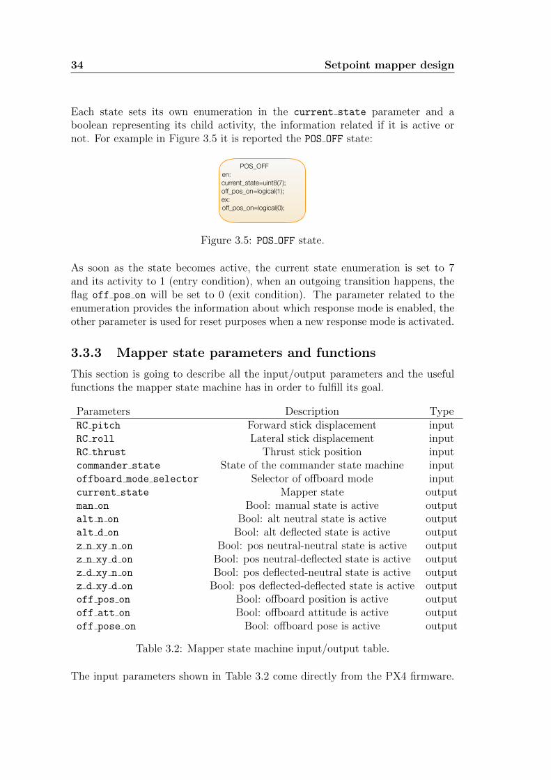
Each state sets its own enumeration in the current state parameter and aboolean representing its child activity, the information related if it is active ornot. For example in Figure 3.5 it is reported the POS OFF state:
POS_OFF en: current_state=uint8(7); off_pos_on=logical(1); ex: off_pos_on=logical(0);
�1
Figure 3.5: POS OFF state.
As soon as the state becomes active, the current state enumeration is set to 7and its activity to 1 (entry condition), when an outgoing transition happens, theflag off pos on will be set to 0 (exit condition). The parameter related to theenumeration provides the information about which response mode is enabled, theother parameter is used for reset purposes when a new response mode is activated.
3.3.3 Mapper state parameters and functions
This section is going to describe all the input/output parameters and the usefulfunctions the mapper state machine has in order to fulfill its goal.
Parameters Description TypeRC pitch Forward stick displacement inputRC roll Lateral stick displacement inputRC thrust Thrust stick position inputcommander state State of the commander state machine inputoffboard mode selector Selector of offboard mode inputcurrent state Mapper state outputman on Bool: manual state is active outputalt n on Bool: alt neutral state is active outputalt d on Bool: alt deflected state is active outputz n xy n on Bool: pos neutral-neutral state is active outputz n xy d on Bool: pos neutral-deflected state is active outputz d xy n on Bool: pos deflected-neutral state is active outputz d xy d on Bool: pos deflected-deflected state is active outputoff pos on Bool: offboard position is active outputoff att on Bool: offboard attitude is active outputoff pose on Bool: offboard pose is active output
Table 3.2: Mapper state machine input/output table.
The input parameters shown in Table 3.2 come directly from the PX4 firmware.

3.3 Mapper state machine 35
The mapper state machine will subscribe to the topics containing the informationwhich needs. In order to do that, once the overall system has been developedand the Simulink Embedded Coder (see Section 3.7) has been run, the generatedcode will be integrated in the firmware in a custom setpoint mapper module. Thismodule will subscribe to the following topics:
• manual control setpoint.msg, it contains the value of the RC sticks;
• commander state.msg, it contains the value of the current state of the com-mander state machine;
Besides the parameters, the mapper state machine has also two MATLAB functionto take into account the deflections of the radio controller sticks, the RC yaw stickis not considered since it is not useful in the mapping procedure. The first functiontakes as input parameter the thrust of the radio controller and outputs a booleanvalue to represent the neutrality or deflection of the stick. The second functiontakes as input two parameters, the pitch and the roll radio controller sticks andoutputs a boolean value to represent the neutrality or deflection of one of themof both. To summarize:
∆z = 0.05
∆xy = 0.05
f zN(z) =
{1 |z − 0.5| ≤ ∆z
0 otherwise(3.1)
fxyN (x, y) =
{1 |x| ≤ ∆xy ∧ |y| ≤ ∆xy
0 otherwise(3.2)
The ∆z and ∆xy are set by default to 0.05, these values are not hardcoded andthey can be modified.
3.3.4 Mapper state machine transitions
The switching between states is managed by five input variables:
• commander state
• RC pitch
• RC roll
• RC thrust
• offboard mode selector

36 Setpoint mapper design
For sake of simplicity, some defines have been used:
• X=RC pitch as the forward stick displacement;
• Y =RC roll as the lateral stick displacement;
• Z=RC thrust as the throttle stick displacement;
• R=RC yaw as the directional stick displacement;
The commander manages the transitions between the macro-states (so betweenthe main flight modes) based on the current state of its internal state machine, thethrust stick manages the transitions between response modes when altitude modeis enabled, the roll and pitch sticks together with the thrust stick manage thetransitions among response modes when the position mode is enabled, dependingon the neutrality of deflection with respect to the deadzone.Finally the offboard mode selector manages the transitions between the responsemodes of the offboard flight mode depending on the type of the MAVLink messagecoming from the ground station related to the specific offboard mode.In Tables 3.3, 3.4 and 3.5 all the possible transitions between the states and theconsequent action condition are listed. The last column represents the evalutionorder from a state to the next one.
Current state Next state ConditionsEvaluation
orderALT N ALT D NOT(f zN(Z)) -ALT D ALT N f zN(Z) -Z N XY N Z D XY D NOT(f zN(Z)) AND NOT(fxyN (X, Y )) 1Z N XY N Z D XY N NOT(f zN(Z)) AND fxyN (X, Y ) 2Z N XY N Z N XY D f zN(Z) AND NOT(fxyN (X, Y )) 3Z N XY D Z D XY D NOT(f zN(Z)) AND NOT(fxyN (X, Y )) 1Z N XY D Z N XY N f zN(Z) AND fxyN (X, Y ) 2Z N XY D Z D XY N NOT(f zN(Z)) AND fxyN (X, Y ) 3Z D XY N Z N XY N f zN(Z) AND fxyN (X, Y ) 1Z D XY N Z D XY D NOT(f zN(Z)) AND NOT(fxyN (X, Y )) 2Z D XY N Z N XY D f zN(Z) AND NOT(fxyN (X, Y )) 3Z D XY D Z N XY N f zN(Z) AND fxyN (X, Y ) 1Z D XY D Z N XY D f zN(Z) AND NOT(fxyN (X, Y )) 2Z D XY D Z D XY N NOT(f zN(Z)) AND fxyN (X, Y ) 3
Table 3.3: Transitions managed by the RC sticks.

3.3 Mapper state machine 37
Currentmacro-state
Nextmacro-state Conditions Evaluation order
MAN ALT commander state==1 1MAN POS commander state==2 2MAN OFF commander state==7 3ALT MAN commander state==0 1ALT OFF commander state==7 2ALT POS commander state==2 3POS MAN commander state==0 1POS ALT commander state==1 2POS OFF commander state==7 3OFF MAN commander state==0 1OFF ALT commander state==1 2OFF POS commander state==2 3
Table 3.4: Transitions managed by the commander.
Current state Next state Condition Evaluation orderPOS OFF ATT OFF offboard mode selector==1 1POS OFF POSE OFF offboard mode selector==2 2ATT OFF POSE OFF offboard mode selector==2 1ATT OFF POS OFF offboard mode selector==0 2POSE OFF POS OFF offboard mode selector==0 1POSE OFF ATT OFF offboard mode selector==1 2
Table 3.5: Transitions managed by the offboard mode selector.
3.3.5 Offboard mode selector
The offboard mode selector has been implemented in the PX4 firmware for takeinto account the type of the MAVLink messages coming from the ground controlstation. In Table 3.6 offboard mode selector values are shown.
Shorthand Flight mode offboard mode selector
POS OFF offboard position 0POS ATT offboard altitude 1POS POSE offboard pose 2
Table 3.6: Offboard mode selector value table.

38 Setpoint mapper design
3.4 Setpoint computation
The setpoint computation has the purpose to generate the setpoint according tothe response mode. The implementation of this component follows a switch/switch-case/merge logic: it receives the information related to which response mode isactive from the mapper state machine (the value of the current state) andit selects the corresponding switch-case block (the setpoint computation has aswitch-case block for each state of the mapper state machine that corresponds toa specific response mode). Within the selected subsystem, the setpoint calcula-tion is performed; the merge block selects the setpoint computed by the currentlyactive state and routes it to the output of the system.
Switch
. . .
Switch case MAN
Switch case ALT_N
Switch case OFF_POSE
.
.
.
Merge
Merge
Merge
current_state
state_on
att
ang rate
thrust
�1
Figure 3.6: Setpoint computation block diagram.
Figure 3.6 shows the idea behind the block diagram implementation in a simplecase with three states and the three setpoint variables of attitude, angular rateand the thrust for sake of simplicity.
3.4.1 Simulink
For the aim of this thesis, Simulink is used to model the setpoint computationblock. Simulink is an add-on product to MATLAB, it is a graphical programmingenvironment for modeling, simulating and analyzing multi-domain dynamical sys-tems and it is developed by MathWorks. Thanks to a set of customizable block

3.4 Setpoint computation 39
libraries, it enables rapid construction of virtual prototypes to explore design con-cepts at any level of detail, with minimal effort. For the modeling part, Simulinkprovides a GUI for building models as block diagrams simply using the drag-and-drop operations. An interesting feature of Simulink is the possibility to generatecode in C, C++ and other languages starting from a dynamic model. The gener-ated code can be integrated like a source code, static libraries or dynamic librariesinto application running outside of MATLAB and Simulink environment.The idea is use this Simulink feature and integrate the generated code of thesetpoint mapper in the custom firmware.
3.4.2 Input variables
Table 3.7 shows all the signals and parameters the setpoint computation uses inorder to map and compute the setpoint properly.
Parameters DescriptionRC pitch Forward stick displacementRC roll Lateral stick displacementRC thrust Thrust stick displacementRC yaw Yaw stick displacementcurrent state Mapper stateman on Bool: manual state is activealt n on Bool: alt neutral state is activealt d on Bool: alt deflected state is activez n xy n on Bool: pos neutral-neutral state is activez n xy d on Bool: pos neutral-deflected state is activez d xy n on Bool: pos deflected-neutral state is activez d xy d on Bool: pos deflected-deflected state is activeoff pos on Bool: offboard position is activeoff att on Bool: offboard attitude is activeoff pose on Bool: offboard pose is activepos(x) North position in NED earth-fixed framepos(y) East position in NED earth-fixed framepos(z) Down position in NED earth-fixed frameis armed Bool: current arming state is armedvehicle att q Attitude quaternion from NED to body framevehicle local position sp Local position setpoint in NED framevehicle attitude sp Quaternion-based attitude setpointvehicle pose sp Pose setpoint for fully-actuated UAV
Table 3.7: Setpoint computation block input parameters.
The last three parameters are send through offboard commands. For what con-cerns the other parameters, they come from the output of the state machine and

40 Setpoint mapper design
from the PX4 firmware. Section 3.3.3 explained how the state machine subscribesto the uORB messages and the setpoint computation follows the same idea. Inorder to retrieve the information which needs, it can subscribe to:
• manual control setpoint.msg, it contains the value of the RC sticks;
• vehicle local position.msg, it contains the position and velocity of thevehicle, this is estimated based on information coming from the Motion-Capture system (see Section 2.1.4);
• vehicle status.msg, it contains the arming state information;
• vehicle local position setpoint.msg, it contains the setpoint for theoffboard position mode;
• vehicle attitude setpoint.msg, it contains the setpoint for the offboardattitude mode;
• vehicle pose setpoint.msg, it contains the setpoint of the offboard posemode;

3.4 Setpoint computation 41
3.4.3 Output variables
Table 3.8 shows the output variables of the setpoint computation block, that arethe setpoint signals which feed the flight controller.
Parameters Description
q0A(φ0, θ0, ψ0) Desired attitude quaternion
p0 roll angular rate (rad/s)q0 pitch angular rate (rad/s)r0 yaw angular rate (rad/s)p0 roll angular acceleration (rad/s2)q0 pitch angular acceleration (rad/s2)r0 yaw angular acceleration (rad/s2)x0 X position (m)y0 Y position (m)z0 Z position (m)v0x X velocity (m/s)v0y Y velocity (m/s)v0z Z velocity (m/s)a0x X acceleration (m/s2)a0y Y acceleration (m/s2)a0z Z acceleration (m/s2)a0x X jerk (m/s3)a0y Y jerk (m/s3)a0z Z jerk (m/s3)a0x X snap (m/s4)a0y Y snap (m/s4)a0z Z snap (m/s4)T 0 Thrust
Table 3.8: Setpoint computation output variables.
The output of the setpoint computation block, together with the informationrelated to the state of the mapper state machine, constitutes the output of thesetpoint mapper system (the information related to the mapper state has beenused for testing purposes and it is not useful for the flight controller).In order to feed the flight controller module, it has been created a uORB topicwhich contains all the computed setpoint: flight controller setpoint.msg.

42 Setpoint mapper design
3.4.4 Mapping laws
The role of the setpoint computation block is mapping the pilot and offboard com-mands to the setpoint that will feed the flight controller. This mapping dependson the current response mode and Table 3.9 explains how the radio controllersticks have been mapped for the computation of the setpoint.
Current state X Y Z RMAN θ0 φ0 T 0 ψ0
ALT N θ0 φ0 z0 ψ0
ALT D θ0 φ0 v0z ψ0
POS Z N XY N x0 y0 z0 ψ0
POS Z N XY D v0x v0y z0 ψ0
POS Z D XY N x0 y0 v0z ψ0
POS Z D XY D v0x v0y v0z ψ0
OFF POS - - - -
OFF ATT - - - -
OFF POSE - - - -
Table 3.9: Mapping laws table for RC modes.
The vertical axis represents the response mode while the horizontal axis the radiocontroller sticks defined in Section 3.3.4. This mapping is consistent with the com-mand style/hold capability associated with the flight modes, reported in Section2.5.

3.4 Setpoint computation 43
3.4.5 Radio setpoint computation
In the previous section it was presented how the sticks are mapped for the setpointcomputation, this section is going to describe how the setpoint has been computed.Parameters used in the computation are defined in Section 3.5.
• longitudinal stick X ∈ [−1, 1] (positive up)
• lateral stick Y ∈ [−1, 1] (positive right)
• throttle stick Z ∈ [0, 1] (positive up)
• directional stick R ∈ [−1, 1] (positive right)
Thrust - T 0
T ′ =
{2TZ Z < Z
T + 2(1− T )(Z − Z) Z ≥ Z(3.3)
where T represents the normalized thrust needed to maintain the UAV in hover.The idea is that the Z stick should stay in the middle position Z = 0.5 whenhovering; this is done by remapping the Z stick to thrust as a piecewise linearfunction. In case T = 0.5, the expression simplifies to T ′ = Z. Afterwards, are-scaling procedure follows.
T ′′ =
{T ′ T ′ < MPC MANTHR MAX
MPC MANTHR MAX T ′ ≥ MPC MANTHR MAX(3.4)
T 0 =
{MPC MANTHR MIN T ′′ < MPC MANTHR MIN
T ′′ T ′′ ≥ MPC MANTHR MIN(3.5)
Pitch angle - θ0
(positive nose up)
θ0 = −MPC MAN TILT MAX ·X (3.6)
Roll angle - φ0
(positive right wing down)
φ0 = MPC MAN TILT MAX · Y (3.7)

44 Setpoint mapper design
Yaw angle - ψ0
(positive clockwise from above)
r0 = MPC MAN Y MAX ·R (3.8)
ψ0(t) = ψ0(t0) +
∫ t
t0
r0(τ)dτ t ≥ t0 (3.9)
ψ0(t0) = ψ(t0) (3.10)
Vertical velocity - v0z
First, the throttle stick is remapped from [0,1] to up and down command [-1,1].
Z ′ = (Z − 0.5) ∗ 2 (3.11)
f(x) =
0 −∆ ≤ x ≤ ∆
x−∆
1−∆∆ < x ≤ 1
x+ ∆
1−∆−1 ≤ x < ∆
(3.12)
g(x) = (1− e)x+ x3 (3.13)
where
∆ =MPC HOLD DZ
2
e = MPC Z MAN EXPO
v0z = −(g(f(Z ′)) (3.14)
In-plane velocity - v0x, v0y
vB,0x = V MAXXY X (3.15)
vB,0y = V MAXXY Y (3.16)
where the B superscript indicates velocity is expressed in body frame. The bodyframe velocity setpoint is then rotated in inertial NED frame.[
v0xv0y
]= R(ψ)
[vB,0x
vB,0y
](3.17)

3.4 Setpoint computation 45
where
R(ψ) =
[cos(ψ) − sin(ψ)sin(ψ) cos(ψ)
](3.18)
v0 =
[g(f(v0x))g(f(v0y))
](3.19)
h(v) =
v |v| ≤ 1v
|v||v| > 1
v ∈ R2 (3.20)
h(v0) =
[v0xv0y
](3.21)
Position - x0, y0, z0
(same for x0, y0, z0)
x0(t) = x0(t0) t ≥ t0 (3.22)
x0(t0) = x(t0) (3.23)
which means that the position measurement at time instant t0 is used as a constantposition setpoint from that time on.

46 Setpoint mapper design
Figure 3.7 shows the switch-case setpoint computation block for the manual modeas an example, the other subsystems follow the same structure.
Figure 3.7: Switch case: manual mode.
The block receives the information which needs to perfom the computation andoutputs the setpoint that are going to feed the flight controller.The setpoint computation output of all the switch-case blocks is summarizedin Table 3.10 (the Att setpoint follows the formalism used in the other tables:q0A(φ0, θ0, ψ0)).For sake of simplicity, the setpoints which are not relevant or applicable to aparticular mode are set to zero.Selecting the current signal value of a signal as a setpoint is equivalent to openingthe feedback loop on that particular signals (i.e. the tracking error is set to zero)e.g. Z D XY D.In order to compute a generic value at time t0 a custom Simulink componentnamed “Hold on rising” has been implemented that acts as follows: as soon as astate becomes active and the flag related of its activity rises, the hold on risingblock has a detect rising block in order to perceive the rising activity.Then, thanks to a memory block, it is able to read the value at time t0 and holdthe output at that value. The implementation is depicted in Figure 3.8.

3.4 Setpoint computation 47
Setpoint MAN ALT N ALT D Z N XY N Z N XY D Z D XY N Z D XY D
Att
φ0
θ0
ψ0
φ0
θ0
ψ0
φ0
θ0
ψ0
φ0=0θ0=0ψ0
φ0=0θ0=0ψ0
φ0=0θ0=0ψ0
φ0=0θ0=0ψ0
Ang
rate0 0 0 0 0 0 0
Ang
acc0 0 0 0 0 0 0
Pos
x(t0)y(t0)z(t0)
x(t0)y(t0)z(t0)
x(t0)y(t0)z(t)
x(t0)y(t0)z(t0)
x(t)y(t)z(t0)
x(t0)y(t0)z(t)
x(t)y(t)z(t)
Vel 0 0
v0x=0
v0y=0
v0z
0
v0xv0yv0z=0
v0x=0
v0y=0
v0z
v0xv0yv0z
Acc 0 0 0 0 0 0 0Jerk 0 0 0 0 0 0 0Snap 0 0 0 0 0 0 0
Thrust T 0 0 0 0 0 0 0
Table 3.10: Setpoint computation output table for RC modes.
Figure 3.8: “Hold on rising” Simulink block.

48 Setpoint mapper design
3.4.6 Offboard setpoint computation
Regarding the offboard modes, the computation of the setpoints has been managedin a different way respect to RC modes. Basically in order to map these setpoint,the setpoint computation should be able to read the content of the uORB messagescontaining the setpoint of the offboard modes and pass them through to the flightcontroller.The topics related to the offboard setpoint are:
• vehicle local position setpoint.msg
• vehicle attitude setpoint.msg
• vehicle pose setpoint.msg
Table 3.11 shows how the offboard modes setpoint are mapped to the outputsetpoint variables.
Setpoint OFF POS OFF ATT OFF POSE
Att q0A(0, 0, ψ0) q0A(φ0, θ0, ψ0) q0A(φ0, θ0, ψ0)
Ang rate 0 0
p0
q0
r0
Ang acc 0 0
p0
q0
r0
Pos
x0
y0
z0
x(t0)y(t0)z(t0)
x0
y0
z0
Vel
v0xv0yv0z
0
v0xv0yv0z
Acc
a0xa0ya0z
0
a0xa0ya0z
Jerk 0 0
a0xa0ya0z
Snap 0 0
a0xa0ya0z
Thrust 0 T 0 0
Table 3.11: Offboard setpoint computation table.

3.4 Setpoint computation 49
Within all the switch-case offboard blocks a security check has been implementedin order to manage the new messages coming from the MAVLink. Thanks to thisimplementation, the vehicle is able to listen to new offboard messages only if it isarmed, starting from the time instant when entering the current state.The Simulink block interfaces with the uORB messages coming from the firmwarethrough bus structures. A bus object has been created for each message reflectingthe structure of the corresponding uORB message and thanks to a bus selectorblock, the information the block needs to generate the setpoint has been extracted.

50 Setpoint mapper design
3.5 PX4 firmware parameters and constants
In order to compute the setpoint properly, the setpoint computation block usessome PX4 parameters and constants. These parameters can also be found in PX4firmware in the mc pos control module, precisely in mc pos control params.c.They are defined externally from the Simulink model in a MATLAB file, namedParameters.m, that is loaded whenever the Simulink block runs. Parameters areshown in Table 3.12.
PX4 parameter DescriptionMPC MAN TILT MAX Max tilt angle in manual or altitude modeMPC MAN Y MAX Max manual yaw rateMPC THR HOVER Hover thrustMPC MANTHR MIN Minimum manual thrustMPC Z MAN EXPO Manual control stick vertical exponential curveMPC XY MAN EXPO Manual position control stick exponential curve sensitivityMPC HOLD DZ Deadzone sticks where position hold is enabled
Table 3.12: PX4 firmware parameters table.
Table 3.13 shows the minimum and maximum value the parameters can assumeand the default value set.
PX4 parameter Min Max DefaultMPC MAN TILT MAX 0.0 90.0 35.0MPC MAN Y MAX 0.0 400.0 200.0MPC THR HOVER 0.1 0.8 0.5MPC MANTHR MIN 0.0 1.0 0.08MPC MANTHR MAX 0.0 1.0 0.9MPC Z MAN EXPO 0 1 0.0MPC XY MAN EXPO 0 1 0.0MPC HOLD DZ 0.0 1.0 0.1
Table 3.13: PX4 parameters min/max table.
Other internally defined parameters are shown in Table 3.14.In the Table 3.14 an interesting parameter is the sample time that represents thesampling time of the system that is 250 Hz.All these parameters are not hardcoded and they can be modified, for examplethe hovering thrust of ANT-1 (see Section 2.6) is about 0.3.

3.6 Flight controller interface 51
Constant DescriptionDEG TO RAD conversion grad to radRAD TO DEG conversion rad to gradTHRESH ARM Z threshold on thrust stick lower value during armingTHRESH ARM R threshold on yaw stick upper value during armingsample time system sampling time
Table 3.14: Constants table.
3.6 Flight controller interface
In order to solve the issues related to the flight controller presented in Section2.6, the interface of the flight controller module has been modified: in additionto the setpoint listed in Table 2.5 the throttle setpoint has been included, sothe resulting interface will concide with the setpoint computation output. Toretrieve the information related to which controllers are to be enabled, the topicvehicle control mode.msg has been considered. The flight controller modulesubscribes to this topic published by the commander that contains the informationabout which controllers to be enabled. These modification allow to expand themanagement also to other flight modes.
3.7 PX4 firmware integration
This section describes how the integration to the custom PX4 firmware has beenperformed. Once the Simulink model of the setpoint mapper system has beendeveloped and all the requirements has been defined, C++ code is automaticallygenerated by the Simulink Embedded Coder and the autogenerated code is readyto be injected in the PX4 firmware. Once defined the I/O interface of the Simulinksetpoint mapper, the next step is to implement it also in the PX4 firmware. Asmentioned previously, PX4 is composed by different modules which correspond tospecific task in the firmware.In this case the creation of a new module will be essential to handle the newmapping system that will be imported from Simulink. The tasks of the newmodule will be to subscribe to the needed topics (those listed in Section 3.3.3 and3.4.2) and to publish a new topic for the flight controller module (Section 3.4.3).The setpoint mapper PX4 module is provided with an interface consistent withthe one defined for the setpoint mapper Simulink model.


Chapter 4
Verification and Testing
This chapter will focus on testing setpoint mapper. A formal testing procedurehas been defined for the mapper state machine. The setpoint computation blocktakes inspiration from the setpoint generation feature implemented in the PX4position controller module; the more interesting part involves the test of the statemachine in order to verify all the possible transitions combination.Besides the setpoint mapper system has been intensively tested in flight envi-ronment with the ANT-1 multirotor UAV (Figure 2.6) and in this section someexperimental results are reported. Furthermore, a couple of experiments havebeen conducted to show the new features involving tiltrotor (Figure 2.7) flightmodes.
4.1 Test harness
The first approach to test the mapper state machine was the test harness. Atest harness is a model block diagram that can be used to test, edit, or debug aSimulink model. In the main model, a test harness can be executed with a modelcomponent or the top-level model. It contains a separate model workspace andconfiguration set; it is associated with the main model and can be accessed viathe model canvas. The test harness model is built around the component undertest and it can be generated for:
• A model component, such as a subsystem, library block, or model block. Thetest harness isolates the component in a separate simulation environment.
• A top-level model, the component under test is a model block referencingthe main model.
For the purpose of this thesis the first option has been used: it has been isolatedthe mapper state machine subsystem.The test harness can be saved internally as a part of the model SLX or externallyin a SLX file. In order to test all the possible transitions five test harnesses have

54 Verification and Testing
been defined and they are kept externally to the main model.
Figure 4.1: External test harnesses.
These test cases cover every possible transition of the state machine, in particular:
• the transitions involving the states within MAN, ALT and POS macro-states.
• the transitions involving the states within the OFF macro-state.
• the transitions involving the macro-states.
Figure 4.2 shows one of the three tests regarding the main flight modes, preciselythe transitions between the response modes (Section 3.2) of the POS macro-state.The purpose of this test is verify, based on the sticks of the radio contoller andthe information of the commander state, that all the transitions between positionresponse modes are feasible. In order to build the test, a repeating sequencestairs has been considered as input signal for RC pitch, RC roll, RC thrust andcommander state. In Table 4.1 are shown all the parameters used for this test.

4.1 Test harness 55
Figure 4.2: Test harness example.
RC pitch RC roll RC thrust commander state time current state
0 0 0.5 0 0 00 0 0.5 2 0.004 30.35 -0.4 0.5 2 0.008 40.55 0 0.75 2 0.012 60 0 0.8 2 0.016 50.5 0.35 0.5 2 0.020 40 0 0.5 2 0.024 3-0.4 0.45 0.5 2 0.028 40 0 0.35 2 0.032 50.4 0.35 0.75 2 0.036 60 0 0.5 2 0.040 30 0 0.9 2 0.044 50 0 0.5 2 0.048 30.49 0.52 0.5 0 0.052 00 0.01 0.5 2 0.056 30 0.5 0.8 2 0.060 60 0.7 0.5 2 0.064 40 0 0.5 2 0.068 30 0 0.7 0 0.072 0
Table 4.1: Test harness parameters table.
For this test purpose, the offboard mode selector is useless and it is triviallyset to 0. The results of this test are consistent with the enumeration defined inSection 3.3.2.

56 Verification and Testing
4.2 Simulink design verifier
The second approach to test the mapper state machine was based on the SimulinkDesign Verifier tool [12]. This tool uses formal methods to identify hidden designerrors in models. It detects blocks in the model that result in integer overflow,dead logic, array access violations and division by zero. It can formally verify thatthe design meets functional requirements. For each design error or requirementsviolation, it generates a simulation test case for debugging.Simulink Design Verifier generates test cases for model coverage and custom ob-jectives to extend existing requirements-based test cases. These test cases drivethe model to satisfy condition, decision and custom coverage objectives.The Design Verifier has been run for the mapper state machine and in Figure 4.3the summary of the analysis has been reported.
�1
Figure 4.3: Summary of the Design Verifier analysis.
The results of the analysis show that there are six objectives proven unsatisfiable:Simulink Design Verifier proved that there does not exist any test case exercisingfor these test objectives. This often indicates the presence of dead-logic in themodel. Other possible reasons can be inactive blocks in the model due to param-eter configuration or test constraints.Figure 4.4 reports the six elements proven unsatisfiable. In fact a redundancyhas been identified in the transition conditions within the POS macro-state. Thisredundancy comes to the fact that Stateflow assigns a priority for each transitionarrow (Section 3.3.4 and Table 3.3) and there are some conditions that are neverconsidered during the analysis because they are always true or false due to theevaluating order of the state machine. However, in the case under exam it was ver-ified that, whenever a state transition condition is highlighted by the verification

4.2 Simulink design verifier 57
�1
Figure 4.4: Objectives proven unsatisfiable.
tool, the redundancies involve only a part of the state transition condition, butthe overall condition is still guaranteed not to be affected by dead logic paths; inparticular, the expressions related to such conditions could be rewritten in orderto eliminate the redundancy and improve the efficiency of the system, but do notjeopardize the coverage of the state machine graph.As a consequence of the result of this analysis it has been decided not to removethis redundancy in order to maintain clarity of the state transition condition ex-pressions.

58 Verification and Testing
4.3 Flight testing
In order to test the setpoint mapper, two different machines have been used:ANT-1 and tiltrotor.
4.3.1 Test on ANT-1
Three different experiments were designed to test the management of the flightmodes and the consequent setpoint generation based on the current response modeenabled. Figure 4.5 shows the different mapping of the throttle stick with respectto the manual and altitude modes. As long as the manual mode is enabled (theenumeration associated to the mapper state is 0), the thrust is mapped as T 0
that corresponds to a re-scaling of the input thrust stick value.As soon as the altitude mode is enabled, specifically a deflection of the thruststick corresponds to the ALT D response mode of the mapper state machine(mapper state is equal to 2), the thrust stick is mapped as a velocity commandin the vertical direction.
45 50 55 60 65 70 75 80 85 900
1
2
ma
pp
er
sta
te
Manual and altitude modes
45 50 55 60 65 70 75 80 85 900
0.5
1Z stick
thrust setpoint
45 50 55 60 65 70 75 80 85 90
time [s]
-2
0
2
vz [
m/s
]
measurement
setpoint
Figure 4.5: Experimental results ANT-1 test 1.
The mapper state value equal to 1 corresponds to the ALT N response mode whichmeans the thrust stick within the deadband: v0z=0.

4.3 Flight testing 59
Figure 4.6 shows the switching between the Z N XY N and Z N XY D response modeswithin the POS macro-state focusing on the lateral stick mapping and the positionhold capability. When the Z N XY D response mode is enabled (the lateral stick isdeflected and the mapper state value is set to 4), the stick value is mapped asvelocity command in the lateral direction.As soon as the Z N XY N response mode is enabled (the lateral stick within thedeadband and the enumeration associated of the mapper state is 3), the multi-copter has the capability to hold the position at the time instant of the switchingto the current mode (Z N XY N). The position measurement at that time instant,is kept as position setpoint y0.
64 65 66 67 68 69 70 71 72 73 74
3
4
sta
te
-1
0
1
Y s
tick
Velocity command, position hold
64 65 66 67 68 69 70 71 72 73 74-5
0
5
vy [
m/s
] measurement
setpoint
64 65 66 67 68 69 70 71 72 73 74
time [s]
-4
-2
0
y [
m]
measurement
setpoint
Figure 4.6: Experimental results ANT-1 test 2A.
Figure 4.7 describes a further experiment conducted to highlight the position holdcapability.

60 Verification and Testing
86 86.5 87 87.5 88 88.5 89 89.5 90 90.5 91
3
4
sta
te
-1
0
1
Y s
tick
Velocity command, position hold
86 86.5 87 87.5 88 88.5 89 89.5 90 90.5 91-5
0
5
vy [
m/s
] measurement
setpoint
86 86.5 87 87.5 88 88.5 89 89.5 90 90.5 91
time [s]
-4
-2
0
y [
m]
measurement
setpoint
Figure 4.7: Experimental results ANT-1 test 2B.
When the lateral stick is centered, the v0y is not considered anymore and theposition hold capability is enabled. In fact the position measurement at the timeinstant of the switching to the Z N XY N response mode (∼87.7s) is kept as aposition setpoint y0 till a deflection of the lateral stick occurs.

4.3 Flight testing 61
Figure 4.8 shows the experiment involving the switching between the offboardmode and position mode and vice versa (precisely OFF POS and the Z N XY N re-sponse modes). At time instant ∼43s the multicopter is in offboard position mode(the enumeration associated to the mapper state is 7) which the position holdcapability is enabled. After few seconds a series of position setpoints representinga trajectory is sent from the ground station and the vehicle according to the set-point contained in the message, tracks the setpoint. Afterwards, a switching to aposition flight mode occurs and the Z N XY N response mode is enabled. As soon asthis new mode is enabled, the position measurement is kept as a position setpointy0 corresponding to the measured position at that time instant since the positionhold capability is enabled. Then, the offboard mode is enabled again. The vehiclealso in this case holds the setpoint corresponding to the position measurement atthe time instant of switching to the OFF POS response mode as a position setpointtill a new series of setpoint commands is sent.
40 45 50 55 60 65 70 75 80 85 90
3
4
5
6
7
sta
te
Position and offboard modes
40 45 50 55 60 65 70 75 80 85 90
time [s]
-6
-4
-2
0
2
y [
m]
measurement
setpoint
Figure 4.8: Experimental results ANT-1 test 3.

62 Verification and Testing
4.3.2 Test on tiltrotor
The setpoint mapper system was tested on tiltrotor. The developed system hasallowed to implement new features in terms of flight modes it can perform. Infact, the tiltrotor was only able to perform trajectory based on the setpoint inoffboard pose mode sent by the ground control station. In addition of the offboardmodes, the setpoint mapper, together with a modification in the flight controllermodule, has enabled the management of the main flight modes: manual, altitudeand position. The tiltrotor has an over-actuated structure and it is able to achievemaneuvers that simple quadrotors are not able to perform. The next experimentsshow the setpoint mapper system tested on the tiltrotor.
120 122 124 126 128 130 132 134 136 138-50
0
50
ph
i [d
eg
]
Tiltrotor: altitude mode
120 122 124 126 128 130 132 134 136 138-20
0
20
the
ta [
de
g]
120 122 124 126 128 130 132 134 136 138
time [s]
-1
-0.95
-0.9
z [
m/s
]
measurement
setpoint
Figure 4.9: Experimental results tiltrotor test 1.
Figure 4.9 shows the altitude mode that corresponds to hovering, keeping non-zeroroll/pitch angles (the tiltrotor has the capability to reach a full position/attitudedecoupling). Depending on the deflection of the X, Y sticks of the Radio Con-troller, the tiltrotor performs its tilting capability; the φ and θ measurementsfollow the setpoints.

4.3 Flight testing 63
-1.28 -1.26 -1.24 -1.22 -1.2 -1.18 -1.16
y [m]
0.31
0.32
0.33
0.34
0.35
0.36
0.37
0.38
0.39
0.4
0.41
x [
m]
Tiltrotor, altitude mode: in-plane position
Figure 4.10: Experimental results in-plane tiltrotor test 1.
In Figure 4.10 is shown the in-plane position that tiltrotor performs according tothe experimental results presented in Figure 4.9.

64 Verification and Testing
Figure 4.11 shows the switching between the Z N XY N and Z N XY D responsemodes within the POS macro-state focusing on the lateral stick. When the Z N XY D
response mode is enabled (the lateral stick is deflected and the mapper state valueis set to 4), the stick value is mapped as velocity command in the lateral directionand thanks to its tilting capability, the tiltrotor is able to maintain a zero rollangle even when maneuvering at high speed. It can be noticed that the roll anglereaches relatively large values in correspondence of braking maneuvers, when thevelocity setpoint suddenly goes to zero: the flight controller could be improved toavoid this aggressive response. As soon as the Z N XY N response mode is enabled(the lateral stick within the deadband and the enumeration associated of themapper state is 3), the setpoint velocity v0y is set to 0.
155 160 165 170 175
3
4
sta
te
Tiltrotor: position mode
155 160 165 170 175-5
0
5
vy [
m/s
]
measurement
setpoint
155 160 165 170 175
time [s]
-20
0
20
ph
i [d
eg
]
Figure 4.11: Experimental results tiltrotor test 2.

Chapter 5
Conclusions
This thesis has involved the design and implementation of a flight mode man-agement and setpoint generation system and also the modification of the customflight controller module.The main objectives have been, on the one hand, to re-implement the setpointgeneration system managed by the position controller module in the PX4 firmwarein order to separate the setpoint generation from core PID control, on the otherhand, to modify the interface of the custom flight controller module in order toextend the management of the main flight modes.The developed system handles the setpoint generation based on the current flightmode enabled; it is also important to notice that it facilitates the integration ofnew flight modes.In fact, from an architectural point of view, the choice of using a de-centralizedarchitecture related to the setpoint mapper and the flight controller, makes thetask of the integration of a new flight mode more straightforward.Some possible developments are the following:
• refactor the setpoint computation block using a centralized architecture tomanage the computation of the setpoint within the mapping of the currentflight mode.
• improve the flight controller to avoid an aggressive response whenever theroll angle reaches relatively large values in correspondence of braking ma-neuvers, when the velocity setpoint suddenly goes to zero.


Bibliography
[1] P. Gattazzo. Nonlinear control of a tilt-arm quadrotor UAV. Master thesis,2017.
[2] Micheli. Design, identification and control of a tiltrotor quadcopter uav.Master thesis, 2016.
[3] L. Meier. PixHawk Autopilot. http://www.pixhawk.org, 2008.
[4] Motive. Optitrack. http://optitrack.com/products/motive.
[5] Microsoft. Windows 10 Pro. https://www.microsoftstore.com/store/
mseea/it_IT/pdp/Windows-10-Pro/productID.320433200.
[6] Canonical. Ubuntu 16.04 lts. https://www.ubuntu.com.
[7] Open Source Robotic Foundation OSRF. ROS. http://www.ros.org.
[8] L. Meier. Px4 Firmware. https://github.com/PX4/Firmware, 2008.
[9] GitHub.com. GitHub Px4 issues. https://github.com/PX4/Firmware/
issues.
[10] MathWorks. Simulink. https://www.mathworks.com/products/simulink.html.
[11] MathWorks. Stateflow. https://mathworks.com/products/stateflow.
html.
[12] MathWorks. Simulink design verifier. https://mathworks.com/products/
sldesignverifier.html.